EP3078467A1 - Tire preheating apparatus, tire vulcanization system, tire preheating method, and tire manufacturing method - Google Patents
Tire preheating apparatus, tire vulcanization system, tire preheating method, and tire manufacturing method Download PDFInfo
- Publication number
- EP3078467A1 EP3078467A1 EP15871289.3A EP15871289A EP3078467A1 EP 3078467 A1 EP3078467 A1 EP 3078467A1 EP 15871289 A EP15871289 A EP 15871289A EP 3078467 A1 EP3078467 A1 EP 3078467A1
- Authority
- EP
- European Patent Office
- Prior art keywords
- tire
- green tire
- bladder
- temperature
- heater
- Prior art date
- Legal status (The legal status is an assumption and is not a legal conclusion. Google has not performed a legal analysis and makes no representation as to the accuracy of the status listed.)
- Withdrawn
Links
- 238000004073 vulcanization Methods 0.000 title claims abstract description 169
- 238000000034 method Methods 0.000 title claims description 17
- 238000004519 manufacturing process Methods 0.000 title claims description 12
- 238000010438 heat treatment Methods 0.000 claims abstract description 65
- 238000006243 chemical reaction Methods 0.000 claims abstract description 20
- 230000005855 radiation Effects 0.000 description 20
- 238000010521 absorption reaction Methods 0.000 description 12
- 239000000919 ceramic Substances 0.000 description 12
- 239000011324 bead Substances 0.000 description 10
- 230000007423 decrease Effects 0.000 description 9
- 238000009826 distribution Methods 0.000 description 9
- OKTJSMMVPCPJKN-UHFFFAOYSA-N Carbon Chemical compound [C] OKTJSMMVPCPJKN-UHFFFAOYSA-N 0.000 description 7
- 229910052799 carbon Inorganic materials 0.000 description 7
- 230000020169 heat generation Effects 0.000 description 7
- VYPSYNLAJGMNEJ-UHFFFAOYSA-N Silicium dioxide Chemical compound O=[Si]=O VYPSYNLAJGMNEJ-UHFFFAOYSA-N 0.000 description 6
- 239000000654 additive Substances 0.000 description 5
- 230000004308 accommodation Effects 0.000 description 4
- 239000002184 metal Substances 0.000 description 4
- 230000000694 effects Effects 0.000 description 3
- 239000000463 material Substances 0.000 description 3
- 239000000377 silicon dioxide Substances 0.000 description 3
- IJGRMHOSHXDMSA-UHFFFAOYSA-N Atomic nitrogen Chemical compound N#N IJGRMHOSHXDMSA-UHFFFAOYSA-N 0.000 description 2
- 230000000996 additive effect Effects 0.000 description 2
- 238000001816 cooling Methods 0.000 description 2
- 229910001873 dinitrogen Inorganic materials 0.000 description 2
- 239000007789 gas Substances 0.000 description 2
- 238000000465 moulding Methods 0.000 description 2
- 239000011347 resin Substances 0.000 description 2
- 229920005989 resin Polymers 0.000 description 2
- 206010010814 Contracted bladder Diseases 0.000 description 1
- 238000013459 approach Methods 0.000 description 1
- 230000005540 biological transmission Effects 0.000 description 1
- 230000003247 decreasing effect Effects 0.000 description 1
- 238000013461 design Methods 0.000 description 1
- 238000005516 engineering process Methods 0.000 description 1
- 239000007788 liquid Substances 0.000 description 1
- 238000012986 modification Methods 0.000 description 1
- 230000004048 modification Effects 0.000 description 1
- 238000003825 pressing Methods 0.000 description 1
- XLYOFNOQVPJJNP-UHFFFAOYSA-N water Substances O XLYOFNOQVPJJNP-UHFFFAOYSA-N 0.000 description 1
Images



Classifications
-
- B—PERFORMING OPERATIONS; TRANSPORTING
- B29—WORKING OF PLASTICS; WORKING OF SUBSTANCES IN A PLASTIC STATE IN GENERAL
- B29D—PRODUCING PARTICULAR ARTICLES FROM PLASTICS OR FROM SUBSTANCES IN A PLASTIC STATE
- B29D30/00—Producing pneumatic or solid tyres or parts thereof
- B29D30/06—Pneumatic tyres or parts thereof (e.g. produced by casting, moulding, compression moulding, injection moulding, centrifugal casting)
- B29D30/0601—Vulcanising tyres; Vulcanising presses for tyres
- B29D30/0662—Accessories, details or auxiliary operations
-
- B—PERFORMING OPERATIONS; TRANSPORTING
- B29—WORKING OF PLASTICS; WORKING OF SUBSTANCES IN A PLASTIC STATE IN GENERAL
- B29C—SHAPING OR JOINING OF PLASTICS; SHAPING OF MATERIAL IN A PLASTIC STATE, NOT OTHERWISE PROVIDED FOR; AFTER-TREATMENT OF THE SHAPED PRODUCTS, e.g. REPAIRING
- B29C33/00—Moulds or cores; Details thereof or accessories therefor
- B29C33/02—Moulds or cores; Details thereof or accessories therefor with incorporated heating or cooling means
-
- B—PERFORMING OPERATIONS; TRANSPORTING
- B29—WORKING OF PLASTICS; WORKING OF SUBSTANCES IN A PLASTIC STATE IN GENERAL
- B29C—SHAPING OR JOINING OF PLASTICS; SHAPING OF MATERIAL IN A PLASTIC STATE, NOT OTHERWISE PROVIDED FOR; AFTER-TREATMENT OF THE SHAPED PRODUCTS, e.g. REPAIRING
- B29C35/00—Heating, cooling or curing, e.g. crosslinking or vulcanising; Apparatus therefor
- B29C35/02—Heating or curing, e.g. crosslinking or vulcanizing during moulding, e.g. in a mould
-
- B—PERFORMING OPERATIONS; TRANSPORTING
- B29—WORKING OF PLASTICS; WORKING OF SUBSTANCES IN A PLASTIC STATE IN GENERAL
- B29D—PRODUCING PARTICULAR ARTICLES FROM PLASTICS OR FROM SUBSTANCES IN A PLASTIC STATE
- B29D30/00—Producing pneumatic or solid tyres or parts thereof
- B29D30/0005—Pretreatment of tyres or parts thereof, e.g. preheating, irradiation, precuring
-
- B—PERFORMING OPERATIONS; TRANSPORTING
- B29—WORKING OF PLASTICS; WORKING OF SUBSTANCES IN A PLASTIC STATE IN GENERAL
- B29D—PRODUCING PARTICULAR ARTICLES FROM PLASTICS OR FROM SUBSTANCES IN A PLASTIC STATE
- B29D30/00—Producing pneumatic or solid tyres or parts thereof
- B29D30/06—Pneumatic tyres or parts thereof (e.g. produced by casting, moulding, compression moulding, injection moulding, centrifugal casting)
- B29D30/0601—Vulcanising tyres; Vulcanising presses for tyres
- B29D30/0605—Vulcanising presses characterised by moulds integral with the presses having radially movable sectors
-
- B—PERFORMING OPERATIONS; TRANSPORTING
- B29—WORKING OF PLASTICS; WORKING OF SUBSTANCES IN A PLASTIC STATE IN GENERAL
- B29D—PRODUCING PARTICULAR ARTICLES FROM PLASTICS OR FROM SUBSTANCES IN A PLASTIC STATE
- B29D30/00—Producing pneumatic or solid tyres or parts thereof
- B29D30/06—Pneumatic tyres or parts thereof (e.g. produced by casting, moulding, compression moulding, injection moulding, centrifugal casting)
- B29D30/0601—Vulcanising tyres; Vulcanising presses for tyres
- B29D30/0654—Flexible cores therefor, e.g. bladders, bags, membranes, diaphragms
-
- B—PERFORMING OPERATIONS; TRANSPORTING
- B29—WORKING OF PLASTICS; WORKING OF SUBSTANCES IN A PLASTIC STATE IN GENERAL
- B29D—PRODUCING PARTICULAR ARTICLES FROM PLASTICS OR FROM SUBSTANCES IN A PLASTIC STATE
- B29D30/00—Producing pneumatic or solid tyres or parts thereof
- B29D30/06—Pneumatic tyres or parts thereof (e.g. produced by casting, moulding, compression moulding, injection moulding, centrifugal casting)
- B29D30/0601—Vulcanising tyres; Vulcanising presses for tyres
- B29D30/0662—Accessories, details or auxiliary operations
- B29D2030/0675—Controlling the vulcanization processes
- B29D2030/0677—Controlling temperature differences
Definitions
- the present invention relates to a tire preheating apparatus, a tire vulcanizing system, a tire preheating method, and a tire manufacturing method.
- a green tire which is molded by a molding machine is vulcanized by a vulcanizing apparatus.
- portions in which rubber thicknesses or kinds of rubber are different from each other may exist in the tire.
- ease of heat transmission or ease of vulcanization reaction may be different from each other, and in the green tire which is formed of the materials of this tire, a region (easy vulcanization region) which is easily subjected to the vulcanization and a region (difficult vulcanization region) which is not easily subjected to the vulcanization exist.
- the present invention is made in consideration of the above-described circumstances, and an object thereof is to provide a tire preheating apparatus, a tire vulcanizing system, a tire preheating method, and a tire manufacturing method capable of preheating a green tire in a temperature distribution which suitably corresponds to each of the easy vulcanization region and the difficult vulcanization region with respect to the green tire having the easy vulcanization region and the difficult vulcanization region.
- a tire preheating apparatus including: an external preheating portion which surrounds the outside of a green tire having an easy vulcanization region and a difficult vulcanization region, and heats the green tire to a normal temperature or more from an outer surface side of the green tire at a temperature less than the temperature at which a vulcanization reaction is promoted in the green tire; and an internal preheating portion which is disposed inside the green tire, and heats the green tire to a normal temperature or more from an inner surface side of the green tire at a temperature less than the temperature at which a vulcanization reaction is promoted in the green tire, in which the external preheating portion includes: a first tire heater which heats an outer surface of the easy vulcanization region; and a second tire heater which heats an outer surface of the difficult vulcanization region at a higher heating value than that of the first tire heater.
- the second tire heater heats the outer surface of the difficult vulcanization region by a higher heating value than that generated by the heating of the first tire heater with respect to the outer surface of the easy vulcanization region, it is possible to transmit more heat to the outer surface of the difficult vulcanization region relative to the outer surface of the easy vulcanization region within a period of time from starting of preheating using the tire preheating apparatus to ending of the preheating.
- a tire vulcanizing system including: the tire preheating apparatus according to the above aspect; a tire vulcanizing apparatus which vulcanizes a green tire which is heated from a normal temperature to a temperature less than a temperature at which a vulcanization reaction is promoted by the tire preheating apparatus, in which the tire vulcanizing apparatus includes: a tire mold which surrounds the outside of the green tire; a bladder which is disposed inside the green tire and pressurizes the green tire from an inner surface side of the green tire toward the tire mold side; and a bladder preheating portion which heats an outer surface of the bladder from the normal temperature to the temperature less than the temperature at which the vulcanization reaction is promoted in the green tire.
- the bladder preheating portion preheats the outer surface of the bladder, a temperature difference between the green tire which is preheated by the tire preheating apparatus at the temperature in the vicinity of the vulcanization promotion temperature and the outer surface of the bladder decreases, and it is possible to prevent a decrease in temperature of the green tire when the green tire preheated by the tire preheating apparatus comes into contact with the bladder.
- the tire vulcanizing system it is possible to appropriately vulcanize the green tire even when a heating time decreases.
- the bladder preheating portion may include: a first bladder heater which heats a region of the outer surface of the bladder which comes into contact with the inner surface of the easy vulcanizing region; and a second bladder heater which heats a region of the outer surface of the bladder which comes into contact with the inner surface of the difficult vulcanization region at a higher heating value than that of the first bladder heater.
- the bladder can come into contact with the inner surface of the green tire in a state where the temperature distribution is generated in which the temperature in the region of the outer surface of the bladder heated by the second bladder heater is higher than the temperature in the region of the outer surface of the bladder heated by the first bladder heater, the heat which is more than the heat transmitted to the inner surface of the easy vulcanization region can be transmitted to the inner surface of the difficult vulcanization region to promote the vulcanization reaction.
- a tire preheating method including: a step of heating a green tire having an easy vulcanization region and a difficult vulcanization region from an outer surface side of the green tire from a normal temperature to a temperature less than the temperature at which vulcanization of the green tire is promoted by a heating value which is relatively smaller with respect to the easy vulcanization region and is relatively greater with respect to the difficult vulcanization region.
- the tire preheating method it is possible to preheat the green tire having the easy vulcanization region and the difficult vulcanization region from the outer surface side of the green tire such that the heat transmitted to the outer surface of the difficult vulcanization region is more than the heat transmitted to the outer surface of the easy vulcanization region.
- a tire manufacturing method including: a preheating step of heating a green tire having an easy vulcanization region and a difficult vulcanization region from an outer surface side of the green tire from a normal temperature to a preheating temperature less than the temperature at which vulcanization of the green tire is promoted by a heating value which is relatively smaller with respect to the easy vulcanization region and is relatively greater with respect to the difficult vulcanization region; and a vulcanizing step of heating the green tire, which is heated to the preheating temperature, to a temperature exceeding the preheating temperature, and vulcanizing the green tire in a tire mold.
- the tire manufacturing method it is possible to perform vulcanization in a state where unevenness in a vulcanization degree decreases even when the green tire having the easy vulcanization region and the difficult vulcanization region is used as a material.
- a tire manufacturing method including: a tire preheating step of heating a green tire having an easy vulcanization region and a difficult vulcanization region from an outer surface side of the green tire from a normal temperature to a preheating temperature less than the temperature at which vulcanization of the green tire is promoted by a heating value which is relatively smaller with respect to the easy vulcanization region and is relatively greater with respect to the difficult vulcanization region; a bladder preheating step of heating a bladder disposed inside the green tire to vulcanize the green tire such that a surface of the bladder coming into contact with the easy vulcanization region has a relatively low temperature and a surface of the bladder coming into contact with the difficult vulcanization region has a relatively high temperature; and a vulcanizing step of disposing the green tire heated to the preheating temperature in a tire mold, allowing an inner surface of the green tire heated to the preheating temperature to come into contact with the bladder, heating the green tire such
- the tire manufacturing method it is possible to perform vulcanization in a state where unevenness in a vulcanization degree decreases even when the green tire having the easy vulcanization region and the difficult vulcanization region is used a material.
- the tire preheating apparatus capable of preheating the green tire in a temperature distribution which suitably corresponds to each of the easy vulcanization region and the difficult vulcanization region with respect to the green tire having the easy vulcanization region and the difficult vulcanization region.
- a tire vulcanizing system including the tire preheating apparatus is described as an example.
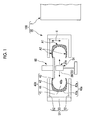
- Fig. 1 is a schematic view of a tire vulcanizing system including a tire preheating apparatus of the present embodiment.
- Fig. 2 is a schematic view showing another configuration example of an internal irradiation-heat heater which is provided in the tire preheating apparatus.
- Fig. 3 is a schematic view showing still another configuration of the internal irradiation-heat heater of the tire preheating apparatus.
- a tire vulcanizing system 100 of the present embodiment shown in Fig. 1 includes a known tire vulcanizing apparatus 1, and a tire preheating apparatus 50 which preheats a green tire 40X carried into the tire vulcanizing apparatus 1.
- the configuration of the tire vulcanizing apparatus 1 is not particularly limited, and detailed illustrations and descriptions thereof are omitted.
- the tire preheating apparatus 50 includes an external preheating portion 51 and an internal preheating portion 54.
- the external preheating portion 51 is disposed to surround the outside of the green tire 40X so as to heat the green tire 40X from an outer surface 40a of the green tire 40X.
- the external preheating portion 51 heats the green tire 40X from the outer surface 40a side of the green tire 40X from a normal temperature to a temperature less than the temperature at which a vulcanization reaction is promoted in the green tire 40X.
- the temperature at which the vulcanization reaction is promoted in the green tire 40X is a temperature which is determined according to a kind of rubber of the green tire 40X or the like, and has the minimum temperature generating the vulcanization reaction suitable for the vulcanization with respect to the green tire 40X as a lower limit.
- the external preheating portion 51 includes a first tire heater 52 and a second tire heater 53.
- the first tire heater 52 and the second tire heater 53 heat the green tire 40X from the outer surface 40a of the green tire 40X by a heating value corresponding to the configuration of the green tire 40X which is an object to be vulcanized.
- a configuration is exemplified in which preheating of the green tire 40X can be suitably performed in a case where the green tire 40X in which a thickness of a tread portion 41 is thicker than a thickness of a side wall 42 is vulcanized.
- the side wall 42 is an easy vulcanization region A2 and the tread portion 41 is a difficult vulcanization region A1.
- the easy vulcanization region A2 and the difficult vulcanization region A1 are not limited to the above-described example, and may be defined according to the configuration of the green tire 40X.
- a configuration in which a thickness of a shoulder portion 44 of the tire 40 is thick may be suitably applied to a run flat tire.
- the thickness of the shoulder portion 44 is thicker than the thickness of the side wall 42, and the shoulder portion 44 may be defined as the difficult vulcanization region A1 while the side wall 42 may be defined as the easy vulcanization region A2.
- the distribution in the preheating temperatures in the tread portion 41 is required to be provided in consideration of influences with respect to vulcanization in the cases.
- the easy vulcanization region A2 and the difficult vulcanization region A1 can be defined in the tread portion 41.
- the first tire heater 52 is a heater which preheats an outer surface 42a of the side wall 42 of the green tire 40X.
- a heat generation method of the first tire heater 52 is not particularly limited.
- the first tire heater 52 may be a heater which comes into contact with the outer surface 42a of the side wall 42 of the green tire 40X to heat the side wall 42.
- the first tire heater 52 may be a heater which heats the side wall 42 via a gaseous heating medium which comes into contact with the outer surface 42a of the side wall 42 of the green tire 40X.
- the first tire heater 52 may be a heater which emits radiation heat toward the outer surface 42a of the side wall 42 of the green tire 40X.
- an infrared heater which emits infrared rays having a wavelength which is easily absorbed to a tire.
- an infrared heater which emits infrared rays having a peak within a range in which an absorption wavelength of the tire is from 1 ⁇ m to 10 ⁇ m, may be adopted as the first tire heater 52 of the present embodiment.
- an infrared heater which emits infrared rays having a peak within a range in which the absorption wavelength of the tire is from 3 ⁇ m to 6 ⁇ m, may be adopted as the first tire heater 52 of the present embodiment.
- an infrared heater which emits infrared rays having a wavelength different from the absorption wavelength of the additive as a peak, may be adopted as the first tire heater 52.
- the second tire heater 53 is a heater which preheats an outer surface 41a of the tread portion 41 of the green tire 40X.
- a heating value of the second tire heater 53 is greater than a heating value of the first tire heater 52.
- the heat generation method of the second tire heater 53 is not particularly limited.
- the second tire heater 53 may be a heater which comes into contact with the outer surface 41a of the tread portion 41 of the green tire 40X to heat the tread portion 41.
- the second tire heater 53 may be a heater which heats the tread portion 41 via a gaseous heating medium which comes into contact with the outer surface 41a of the tread portion 41 of the green tire 40X.
- the second tire heater 53 may be a heater which emits radiation heat toward the outer surface 41a of the tread portion 41 of the green tire 40X.
- the heater which emits radiation heat there is an infrared heater which emits infrared rays having a wavelength which is easily absorbed to a tire.
- an infrared heater which emits infrared rays having a peak within a range in which an absorption wavelength of the tire is from 3 ⁇ m to 6 ⁇ m, may be adopted as the second tire heater 53 of the present embodiment.
- the infrared heater there is a ceramic heater.
- an infrared heater which emits infrared rays having a wavelength different from the absorption wavelength of the additive as a peak, may be adopted as the second tire heater 53.
- a magnitude relationship between the heating value of the first tire heater 52 and the heating value of the second tire heater 53 is determined in consideration of heating capacity per unit area on the outer surface 40a of the green tire 40X which is an object to be heated.
- the magnitude relationship between the heating value of the first tire heater 52 and the heating value of the second tire heater 53 may be determined in consideration of absorption wavelength characteristics on the outer surface 40a of the green tire 40X which is an object to be preheated in a case where both of the first tire heater 52 and the second tire heater 53 are infrared heaters. That is, for example, even when outputs of the first tire heater 52 and the second tire heater 53 configured of infrared heaters are the same as each other, if peak wavelengths of the emitted infrared rays are different from each other, heating capacities per unit area on the outer surface 40a of the green tire 40X are different from each other.
- the heating capacities per unit area on the outer surface 40a of the green tire 40X are different from each other according to the portion.
- the maximum heating values of the first tire heater 52 and the second tire heater 53 are the same as each other, or the first tire heater 52 may be a heater having the maximum heating value greater than that of the second tire heater 53. In this case, when the green tire 40X is preheated, a heat generation state is controlled such that the heating value of the second tire heater 53 is greater than the heating value of the first tire heater 52.
- the internal preheating portion 54 includes an internal irradiation-heat heater 55 which is disposed inside the green tire 40X in a state where the green tire 40X is attached to the tire preheating apparatus 50.
- the internal preheating portion 54 may preheat the inner surface 40b of the green tire 40X using a heating medium such as high-temperature steam or gas.
- an irradiation surface 56 which emits radiation heat toward the inner surface 40b of the green tire 40X is formed.
- the heat emitted from the internal irradiation-heat heater 55 is mainly radiated in a normal direction of the irradiation surface 56.
- the irradiation surface 56 of the internal irradiation-heat heater 55 is configured.
- the irradiation surface 56 of the internal irradiation-heat heater 55 faces a region which is required to be relatively more heated in order to uniformly heat the entire green tire 40X.
- the irradiation surface 56 of the internal irradiation-heat heater 55 has a surface 55a which faces a portion having a thick rubber thickness such that more radiation heat is transmitted to the portion having a thick rubber thickness (tread portion 41 in the present embodiment) of the green tire 40X relative to a portion having a thin rubber thickness (side wall 42 in the present embodiment).
- the configuration of the irradiation surface 56 is not limited to the above-described configuration.
- the irradiation surface 56 of the internal irradiation-heat heater 55 has a surface which faces a portion which is configured of a rubber having a high vulcanization temperature such that more radiation heat is transmitted to the portion which is configured of a rubber having a high vulcanization temperature relative to a portion which is configured of a portion having a lower vulcanization temperature.
- the irradiation surface 56 of the internal irradiation-heat heater 55 has a surface which is defined according to a distance between the internal irradiation-heat heater 55 and the inner surface 40b of the green tire 40X such that more radiation heat is transmitted to a portion positioned at a position far from the internal irradiation-heat heater 55 corresponding to the size of the green tire 40X relative to a portion positioned at a position close to the internal irradiation-heat heater 55.
- the shape of the internal irradiation-heat heater 55 is not particularly limited as long as it has the irradiation surface 56.
- the internal irradiation-heat heater 55 is formed in an approximately rod shape which is long in the tread width direction X of the green tire 40X in a state where the green tire 40X is attached to the tire preheating apparatus 50.
- the outer surface shape of the internal irradiation-heat heater 55 may be a shape (refer to Fig. 1 ) having a columnar shaped irradiation surface 56, a shape (refer to Fig. 2 ) having a curved irradiation surface 56 in which the center portion in the center line direction of a columnar surface is recessed toward the inside in the radial direction, a shape (refer to Fig. 3 ) having an irradiation surface 56 which is formed in a spindle shaped curve in which the center portion in the center line direction of a columnar surface is expanded toward the outside in the radial direction, or the like.
- the internal irradiation-heat heater 55 may have a plurality of heaters (for example, heater 55-1, heater 55-2, heater 55-3, heater 55-4, and heater 55-5) which are arranged in the tread width direction X.
- the heating values from the plurality of heaters are separately controlled, it is possible to control the amount of heat reaching the inner surface 40b of the green tire 40X shown in Fig. 1 .
- the internal irradiation-heat heater 55 a known heat generation method which receives a supply of power to generate heat may be appropriately selected so as to be applied. That is, as the internal irradiation-heat heater 55 of the present embodiment, an infrared heater, a ceramic heater, a carbon heater, or the like may be adopted.
- the wavelength of the radiation heat from the internal irradiation-heat heater 55 is a wavelength (for example, infrared rays having a peak within a range from 3 ⁇ m to 6 ⁇ m) capable of effectively heating the green tire 40X.
- the configurations of the internal irradiation-heat heaters 55 are merely examples, and the internal irradiation-heat heaters 55 of the present embodiment are not limited to the configurations.
- Affects of the tire preheating apparatus 50 of the present embodiment and effects thereof are described along with a tire preheating method and a tire manufacturing method of the present embodiment.
- the tire preheating apparatus 50 of the present embodiment When the tire preheating apparatus 50 of the present embodiment is operated, for example, in a state where a bead 43 of the green tire 40X is supported by a tire holding mechanism 60 schematically shown in Fig. 1 , the green tire 40X is held in the tire preheating apparatus 50.
- the tread portion 41 is more difficult to warm relative to the side wall 42.
- a temperature difference between the outer surface 40a and an intermediate portion 40c in a portion which is thickly formed in the green tire 40X is greater than that of a portion which is thinly formed.
- the outer surface 42a of the side wall 42 is preheated by the first tire heater 52
- the outer surface 41a of the tread portion 41 is preheated by the second tire heater 53
- the inner surface 40b of the green tire 40X is preheated by the internal irradiation-heat heater 55. Accordingly, it is possible to transmit more heat to the tread portion 41 which is the difficult vulcanization region A1 of the green tire 40X relative to the side wall 42 which is the easy vulcanization region A2 of the green tire 40X (tire preheating step).
- the vulcanization reaction is likely to start in the easy vulcanization region A2 in a process in which the difficult vulcanization region A1 is heated from a normal temperature to a temperature less than a vulcanization promotion temperature.
- the difficult vulcanization region A1 for example, tread portion 41
- the easy vulcanization region A2 for example, side wall 42
- the side wall 42 of the green tire 40X is thinner compared to the tread portion 41, if the side wall 42 is excessively heated, the green tire 40X is likely to be deformed due to it's own weight.
- the side wall 42 is preheated by the first tire heater 52 having a lower heating value than that of the second tire heater 53, it is possible to prevent the green tire 40X from being deformed due to it's own weight before the vulcanization.
- the preheated green tire 40X is carried into the tire vulcanizing apparatus 1 having a known tire mold and is vulcanized under predetermined temperature conditions (vulcanizing step).
- the green tire 40X is vulcanized, and a tread pattern, a tread marking, or the like is formed on the green tire 40X.
- preheating corresponding to the positions of the easy vulcanization region A2 and the difficult vulcanization region A1 in the green tire 40X is performed in the tire preheating step such that the preheating temperature becomes the temperature in the vicinity of the vulcanization start temperature less than the vulcanization promotion temperature, it is possible to preheat the green tire in the temperature distribution which suitably corresponds to each of the easy vulcanization region A2 and the difficult vulcanization region A1 with respect to the green tire having the easy vulcanization region A2 and the difficult vulcanization region A1.
- FIG. 5 is a schematic view showing a portion of a tire vulcanizing system of the present embodiment.
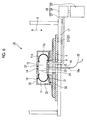
- Figs. 6 and 7 are schematic views showing a bladder preheating device of the tire vulcanizing system.
- a tire vulcanizing system 100A (refer to Fig. 5 ) of the present embodiment includes the tire preheating apparatus 50 (shown in Fig. 1 ) described in the first embodiment, and a tire vulcanizing apparatus 1A (refer to Figs. 5 and 6 ) which performs vulcanization on a tire preheated by the tire preheating apparatus 50.
- the configuration of the tire preheating apparatus 50 of the present embodiment is the same as that of the first embodiment, and descriptions thereof are omitted.
- the tire vulcanizing apparatus 1A of the present embodiment shown in Figs. 5 and 6 includes a tire mold 2, a bladder 10, a center mechanism 14, a mold fixing mechanism 17, a mold lifting and lowering mechanism 18, a tire heating mechanism 20, a pressurization medium supply portion 26, and a bladder preheating portion 30.
- the tire mold 2 includes an upper side mold 3, a lower side mold 4, an upper bead ring 5, a lower bead ring 6, and a tread mold 7.
- the upper side mold 3 and the lower side mold 4 are metal molds for molding both side walls 42 of the tire 40.
- the upper side mold 3 is attached to the mold lifting and lowering mechanism 18.
- the lower side mold 4 is attached to the mold fixing mechanism 17.
- the upper bead ring 5 and the lower bead ring 6 are metal molds for forming both beads 43 of the tire 40.
- the tread mold 7 includes a tread segment 8 and a slide segment 9.
- the tread segment 8 is a metal mold which transfers a tread pattern to the tread portion 41 of the green tire 40X.
- the slide segment 9 holds the tread segment 8 such that the tread segment 8 is movable in a radial direction of the tire 40.
- the slide segment 9 is connected to the mold lifting and lowering mechanism 18.
- the configuration of the tire mold 2 is not limited to the above-described configuration.
- the configuration of the tire mold 2 may be appropriately selected according to a shape of a produced tire or the like.
- a bladder 10 is a hollow member for pressing the green tire 40X disposed inside the tire mold 2 to the tire mold 2 from the inside when the tire vulcanizing apparatus 1A is used.
- the bladder 10 includes a main body portion 11 which has a shape corresponding to the inner surface shape of the green tire 40X vulcanized by the tire vulcanizing apparatus 1A of the present embodiment, and an upper clamp portion 12 and a lower clamp portion 13 which are connected to the center mechanism 14.
- the inner portion of the bladder 10 is filled with a pressurizing medium (air and liquid), and thus, the bladder 10 presses the inner surface 40b of the green tire 40X.
- the bladder 10 is heated by a heater 23 described below, and the green tire 40X can be heated from the inner surface 40b side via the bladder 10.
- the configuration of the bladder 10 is not limited to the above-described configuration.
- the center mechanism 14 includes a pair of bladder clamp rings 15 which is connected the upper clamp portion 12 and the lower clamp portion 13 of the bladder 10, and a center post 16 which is connected to the pair of bladder clamp rings 15.
- the center mechanism 14 moves the pair bladder clamp rings 15 relatively to each other in a center line 16a direction of the center post 16, and displaces the bladder 10 such that the bladder 10 is inserted into and detached from the green tire 40X.
- the configuration of the center mechanism 14 is not limited to the above-described configuration.
- the mold fixing mechanism 17 can support the center mechanism 14 and the lower side mold 4, and supports the bladder preheating portion 30 so as to be movable.
- the mold lifting and lowering mechanism 18 causes the upper side mold 3 and the tread mold 7 to move forward and backward with respect to the lower side mold 4 in the center line 16a direction of the center post 16. Moreover, in the present embodiment, the slide segment 9 of the tread mold 7 moves toward the center post 16 side as the mold lifting and lowering mechanism 18 causes the tread mold 7 to approach the mold fixing mechanism 17.
- the configuration of the mold lifting and lowering mechanism 18 is not limited to the above-described configuration.
- the tire heating mechanism 20 includes an outer heating mechanism 21 which heats the green tire 40X from the outer surface 40a side of the green tire 40X via the upper side mold 3, the lower side mold 4, and the tread mold 7, and an inner heating mechanism 22 which is attached to the center post 16 and heats the green tire 40X from the inner surface 40b side of the green tire 40X.
- the outer heating mechanism 21 has a high-temperature steam channel, and heats the green tire 40X from the outside by the heat of the high-temperature steam.
- the configuration of the outer heating mechanism 21 is not limited to the above-described configuration.
- the inner heating mechanism 22 includes a heater 23 which is attached to the center post 16, and a wire 25 which supplies power to the heater 23.
- the heater 23 heats the tire 40 supported by the upper and lower bead rings 5 and 6 from the inside of the tire 40 by radiation heat. In the present embodiment, the heater 23 heats the tire 40 via the bladder 10. In addition, in a case where the tire vulcanizing apparatus 1A does not include the bladder 10, the heater 23 may directly heat the tire 40 from the inside of the tire 40.
- the shape of the heater 23 is a tubular shape which surrounds the center post 16 and is coaxial with the center line 16a of the center post 16.
- An irradiation surface 24 which emits radiation heat toward the inner surface 40b of the green tire 40X is formed on the outer circumferential surface of the heater 23.
- the known heat generation method which receive power and generates heat may be appropriately selected and adopted. That is, as the heater 23 of the present embodiment, an infrared heater, a ceramic heater, a carbon heater, or the like may be adopted.
- the wavelength of the radiation heat from the heater 23 is a wavelength capable of effectively heating the bladder 10 according to absorption wavelength characteristics of the bladder 10.
- a heater which can suitably heat the bladder 10 according to the absorption wavelength characteristics of a resin such as rubber configuring the bladder 10 there is an infrared heater which has a wavelength of a range from 1 ⁇ m to 10 ⁇ m as a peak.
- the heater which can suitably heat the bladder 10 according to the absorption wavelength characteristics of a resin such as rubber configuring the bladder 10, there is an infrared heater which has a wavelength of an approximately 3.5 ⁇ m as a peak.
- the ceramic heater since a ceramic heater has a peak of a wavelength of radiation heat within a range from 3 ⁇ m to 6 ⁇ m, the ceramic heater is particularly suitable for the heater 23 of the present embodiment.
- a peak of a wavelength of radiation heater may be shorter than that of the ceramic heater.
- the heater 23 may have the configuration ( Figs. 2, 3, and 4 ) similar to that of the internal irradiation-heat heater 55 described in the first embodiment.
- the wire 25 is disposed inside the center post 16 and is connected to the heater 23 and a power supply (not shown).
- the pressurization medium supply portion 26 supplies the pressurizing medium into the bladder 10 when vulcanization with respect to the green tire 40X is performed, and recovers the pressurizing medium from the inside of the bladder 10 after the vulcanization.
- the pressurization medium supply portion 26 includes a pressurization medium pipeline 27 which is provided one or both of the pair of bladder clamp rings 15 and communicates with the inner portion of the bladder 10, a compressor 28 which supplies and extract the pressurizing medium through the pressurization medium pipeline 27, and a pressurization medium accommodation portion 29.
- the pressurizing medium a high-temperature steam, a high-temperature dry gas, or the like may be selected.
- the pressurization medium accommodation portion 29 includes a water tank and a boiler.
- the pressurization medium accommodation portion 29 includes a tank in which nitrogen gas is held.
- the bladder preheating portion 30 shown in Fig. 6 is disposed in the mold fixing mechanism 17 so as to be movable with respect to the bladder 10.
- the bladder preheating portion 30 includes a first bladder heater 31 and a second bladder heater 32.
- the first bladder heater 31 and the second bladder heater 32 heat the bladder 10 from the outer surface of the bladder 10 by a heating value corresponding to the configuration of the green tire 40X (refer to Fig. 5 ) which is an object to be vulcanized.
- the configuration is exemplified in which preheating of the green tire 40X can be suitably performed in the case where the green tire 40X in which a thickness of a tread portion 41 is thicker than a thickness of a side wall 42 is vulcanized.
- the side wall 42 is the easy vulcanization region A2 and the tread portion 41 is the difficult vulcanization region A1.
- the first bladder heater 31 is a heater which heats a region 11a of the outer surface of the bladder 10 which comes into contact with the inner surface of the easy vulcanization region A2 (side wall 42 in the present embodiment) of the green tire 40X.
- the heat generation method of the first bladder heater 31 is particularly not limited.
- the first bladder heater 31 may be a heater which comes into contact with the outer surface of the bladder 10 and heats the bladder 10.
- the first bladder heater 31 may be a heater which comes into contact with the outer surface of the bladder 10 and heats the bladder 10 via a gaseous heating medium.
- the first bladder heater 31 may be a heater which emits radiation heat toward the outer surface of the bladder 10.
- an infrared heater for example, may be a ceramic heater, a carbon heater, or the like
- an infrared heater which emits infrared rays having a wavelength which is easily absorbed to the bladder 10.
- an infrared heater which emits infrared rays having a peak within a range from 3 ⁇ m to 6 ⁇ m which are absorption wavelengths of the bladder 10, may be adopted as the first bladder heater 31 of the present embodiment.
- this infrared heater there is a ceramic heater.
- the second bladder heater 32 is a heater which heats a region 11b of the outer surface of the bladder 10 which comes into contact with the inner surface of the difficult vulcanization region A1 (tread portion 41 in the present embodiment) of the green tire 40X by a higher heating value than that of the first bladder heater 31.
- the heat generation method of the second bladder heater 32 is particularly not limited.
- the second bladder heater 32 may be a heater which comes into contact with the outer surface of the bladder 10 and heats the bladder 10.
- the second bladder heater 32 may be a heater which comes into contact with the outer surface of the bladder 10 and heats the bladder 10 via a gaseous heating medium.
- the second bladder heater 32 may be a heater which emits radiation heat toward the outer surface of the bladder 10. In a case where a heating medium is used or in a case where radiation heat is used, even when the bladder 10 has an expanded shape or even when the bladder 10 has a contracted shape, it is possible to uniformly heat the outer surface of the bladder 10.
- an infrared heater for example, may be a ceramic heater, a carbon heater, or the like
- an infrared heater which emits infrared rays having a wavelength which is easily absorbed to the bladder 10.
- an infrared heater which emits infrared rays having a peak within a range from 3 ⁇ m to 6 ⁇ m which are absorption wavelengths of the bladder 10, may be adopted as the second bladder heater 32 of the present embodiment.
- this infrared heater there is a ceramic heater.
- Affects of the tire preheating apparatus 100A of the present embodiment and effects thereof are described along with a tire preheating method and a tire manufacturing method of the present embodiment.
- the bladder 10 is preheated by the bladder preheating portion 30 (bladder preheating step).
- preheating with respect to the subsequent green tire 40X is performed as described in the first embodiment (tire preheating step).
- the green tire 40X is heated to temperature at which a vulcanization reaction is promoted, and after the time reaches a vulcanization time corresponding to a desired vulcanization degree, the vulcanized tire 40 is cooled in order to prevent excessive vulcanization. In a cooling process of the vulcanized tire 40, the vulcanization reaction is advanced to some extent.
- the bladder 10 is also cooled.
- the temperature of the bladder 10 is further decreased.
- the first bladder heater 31 and the second bladder heater 32 of the bladder preheating portion 30 are disposed so as to surround the bladder 10.
- the bladder preheating portion 30 heats the bladder 10 from the outer surface side of the contracted bladder 10. Accordingly, the temperature of the outer surface of the bladder 10 is kept to temperature which does not significantly exceed the vulcanization promotion temperature on the inner surface 40b of the green tire 40X.
- the temperature of the surface which comes into contact with the easy vulcanization region A2 (side wall 42 in the present embodiment) and the temperature of the surface which comes into contact with the difficult vulcanization region A1 (tread portion 41 in the present embodiment) are kept in a state of being different from each other.
- the temperature of the surface which comes into contact with the inner surface of the tread portion 41 in the outer surface of the bladder 10 is kept to a higher temperature than the temperature of the surface which comes into contact with the inner surface of the side wall 42 in the outer surface of the bladder 10.
- the inner surface 40b of the green tire 40X and the outer surface of the bladder 10 are preheated by the tire preheating apparatus 50 and the bladder preheating portion 30 such that a temperature difference between the inner surface 40b of the green tire 40X and the outer surface of the bladder 10 decreases at mutual contact positions.
- the first bladder heater 31 and the second bladder heater 32 heat the outer surface of the bladder 10 at a temperature from a normal temperature to a temperature less than the temperature at which the vulcanization reaction is promoted in the green tire 40X.
- the bladder 10 may be reheated at a slightly higher temperature than the vulcanization start temperature of the green tire 40X.
- the bladder 10 may be preheated at a slightly higher temperature than the vulcanization start temperature of the green tire 40X.
- the bladder 10 may be preheated by the first bladder heater 31 and the second bladder heater 32 at a higher temperature than the temperature of the inner surface 40b (normal temperature or temperature of the preheated inner surface) of the green tire 40X.
- the subsequent green tire 40X is carried into the tire vulcanizing apparatus 1A.
- the bladder preheating portion 30 is removed from the bladder 10
- the green tire 40X is disposed on the lower side mold 4, and thereafter, the members configuring the tire mold 2 are combined so as to surround the green tire 40X.
- the tire mold 2 and the bladder 10 are heated, the bladder 10 is pressurized, and vulcanization with respect to the green tire 40X starts.
- the temperature of the outer surface of the bladder 10 is higher than the normal temperature since the outer surface of the bladder 10 is preheated by the bladder preheating portion 30, and the temperature of the inner surface 40b of the green tire 40X is higher than the normal temperature since the inner surface 40b of the green tire 40X is preheated by the tire preheating apparatus 50.
- the temperature difference between the bladder 10 and the green tire 40X is small at the contact position therebetween, an amount of movement of heat between the green tire 40X and the bladder 10 is small.
- vulcanization starts in the state where the inner surface 40b of the green tire 40X is preheated in a temperature distribution suitable for each of the side wall 42 (easy vulcanization region A2) and the tread portion 41 (difficult vulcanization region A1).
- the vulcanizing step since vulcanization starts in the state where the green tire 40X is preheated in the temperature distribution suitable for each of the easy vulcanization region A2 and the difficult vulcanization region A1, it is possible to vulcanize the green tire 40X such that vulcanization degrees suitable for the easy vulcanization region A2 and the difficult vulcanization region A1 are realized at a shorter period of time relative to the case where the green tire 40X is heated from the normal temperature.
- the present invention can be used to optimize a temperature distribution at a starting point of vulcanization in a system for vulcanizing a green tire.
Landscapes
- Engineering & Computer Science (AREA)
- Mechanical Engineering (AREA)
- Physics & Mathematics (AREA)
- Health & Medical Sciences (AREA)
- Oral & Maxillofacial Surgery (AREA)
- Thermal Sciences (AREA)
- Moulds For Moulding Plastics Or The Like (AREA)
- Heating, Cooling, Or Curing Plastics Or The Like In General (AREA)
Abstract
Description
- The present invention relates to a tire preheating apparatus, a tire vulcanizing system, a tire preheating method, and a tire manufacturing method.
- In the related art, a green tire which is molded by a molding machine is vulcanized by a vulcanizing apparatus.
- Before vulcanization with respect to a green tire starts, it is possible to decrease the time required for the vulcanization by preheating an unvulcanized green tire (for example, refer to PTL 1 and PTL 2) or preheating a metal mold or a bladder for vulcanizing a green tire (for example, refer to
PTL 3 and PTL 4). -
- [PTL 1]
Japanese Unexamined Patent Application Publication No. 2009-248308 - [PTL 2]
Japanese Unexamined Patent Application Publication No. 2014-076581 - [PTL 3]
Japanese Unexamined Patent Application Publication No. 9-193160 - [PTL 4]
Japanese Patent No. 4998992 - In order to obtain a desired performance of a tire, portions in which rubber thicknesses or kinds of rubber are different from each other may exist in the tire. In the portions in which rubber thicknesses or kinds of rubber are different from each other in the tire, ease of heat transmission or ease of vulcanization reaction may be different from each other, and in the green tire which is formed of the materials of this tire, a region (easy vulcanization region) which is easily subjected to the vulcanization and a region (difficult vulcanization region) which is not easily subjected to the vulcanization exist.
- In the technologies disclosed in PTL 1 to
PTL 4, in a case where the easy vulcanization region and the difficult vulcanization region exist in one kind of green tire, a portion which is appropriately preheated to the vicinity of a temperature at which a vulcanization reaction is promoted, a portion in which preheating is insufficient, and a portion in which preheating is excessive are likely to occur in the green tire. - The present invention is made in consideration of the above-described circumstances, and an object thereof is to provide a tire preheating apparatus, a tire vulcanizing system, a tire preheating method, and a tire manufacturing method capable of preheating a green tire in a temperature distribution which suitably corresponds to each of the easy vulcanization region and the difficult vulcanization region with respect to the green tire having the easy vulcanization region and the difficult vulcanization region.
- According to a first aspect of the present invention, there is provided a tire preheating apparatus, including: an external preheating portion which surrounds the outside of a green tire having an easy vulcanization region and a difficult vulcanization region, and heats the green tire to a normal temperature or more from an outer surface side of the green tire at a temperature less than the temperature at which a vulcanization reaction is promoted in the green tire; and an internal preheating portion which is disposed inside the green tire, and heats the green tire to a normal temperature or more from an inner surface side of the green tire at a temperature less than the temperature at which a vulcanization reaction is promoted in the green tire, in which the external preheating portion includes: a first tire heater which heats an outer surface of the easy vulcanization region; and a second tire heater which heats an outer surface of the difficult vulcanization region at a higher heating value than that of the first tire heater.
- In the tire preheating apparatus, since the second tire heater heats the outer surface of the difficult vulcanization region by a higher heating value than that generated by the heating of the first tire heater with respect to the outer surface of the easy vulcanization region, it is possible to transmit more heat to the outer surface of the difficult vulcanization region relative to the outer surface of the easy vulcanization region within a period of time from starting of preheating using the tire preheating apparatus to ending of the preheating.
- According to a second aspect of the present invention, there is provided a tire vulcanizing system, including: the tire preheating apparatus according to the above aspect; a tire vulcanizing apparatus which vulcanizes a green tire which is heated from a normal temperature to a temperature less than a temperature at which a vulcanization reaction is promoted by the tire preheating apparatus, in which the tire vulcanizing apparatus includes: a tire mold which surrounds the outside of the green tire; a bladder which is disposed inside the green tire and pressurizes the green tire from an inner surface side of the green tire toward the tire mold side; and a bladder preheating portion which heats an outer surface of the bladder from the normal temperature to the temperature less than the temperature at which the vulcanization reaction is promoted in the green tire.
- In the tire vulcanizing system, the bladder preheating portion preheats the outer surface of the bladder, a temperature difference between the green tire which is preheated by the tire preheating apparatus at the temperature in the vicinity of the vulcanization promotion temperature and the outer surface of the bladder decreases, and it is possible to prevent a decrease in temperature of the green tire when the green tire preheated by the tire preheating apparatus comes into contact with the bladder. In addition, according to the tire vulcanizing system, it is possible to appropriately vulcanize the green tire even when a heating time decreases.
- The bladder preheating portion may include: a first bladder heater which heats a region of the outer surface of the bladder which comes into contact with the inner surface of the easy vulcanizing region; and a second bladder heater which heats a region of the outer surface of the bladder which comes into contact with the inner surface of the difficult vulcanization region at a higher heating value than that of the first bladder heater.
- In this case, since the bladder can come into contact with the inner surface of the green tire in a state where the temperature distribution is generated in which the temperature in the region of the outer surface of the bladder heated by the second bladder heater is higher than the temperature in the region of the outer surface of the bladder heated by the first bladder heater, the heat which is more than the heat transmitted to the inner surface of the easy vulcanization region can be transmitted to the inner surface of the difficult vulcanization region to promote the vulcanization reaction.
- According to a third aspect of the present invention, there is provided a tire preheating method, including: a step of heating a green tire having an easy vulcanization region and a difficult vulcanization region from an outer surface side of the green tire from a normal temperature to a temperature less than the temperature at which vulcanization of the green tire is promoted by a heating value which is relatively smaller with respect to the easy vulcanization region and is relatively greater with respect to the difficult vulcanization region.
- According to the tire preheating method, it is possible to preheat the green tire having the easy vulcanization region and the difficult vulcanization region from the outer surface side of the green tire such that the heat transmitted to the outer surface of the difficult vulcanization region is more than the heat transmitted to the outer surface of the easy vulcanization region.
- According to a fourth aspect of the present invention, there is provided a tire manufacturing method, including: a preheating step of heating a green tire having an easy vulcanization region and a difficult vulcanization region from an outer surface side of the green tire from a normal temperature to a preheating temperature less than the temperature at which vulcanization of the green tire is promoted by a heating value which is relatively smaller with respect to the easy vulcanization region and is relatively greater with respect to the difficult vulcanization region; and a vulcanizing step of heating the green tire, which is heated to the preheating temperature, to a temperature exceeding the preheating temperature, and vulcanizing the green tire in a tire mold.
- According to the tire manufacturing method, it is possible to perform vulcanization in a state where unevenness in a vulcanization degree decreases even when the green tire having the easy vulcanization region and the difficult vulcanization region is used as a material.
- According to a fifth aspect of the present invention, there is provided a tire manufacturing method, including: a tire preheating step of heating a green tire having an easy vulcanization region and a difficult vulcanization region from an outer surface side of the green tire from a normal temperature to a preheating temperature less than the temperature at which vulcanization of the green tire is promoted by a heating value which is relatively smaller with respect to the easy vulcanization region and is relatively greater with respect to the difficult vulcanization region; a bladder preheating step of heating a bladder disposed inside the green tire to vulcanize the green tire such that a surface of the bladder coming into contact with the easy vulcanization region has a relatively low temperature and a surface of the bladder coming into contact with the difficult vulcanization region has a relatively high temperature; and a vulcanizing step of disposing the green tire heated to the preheating temperature in a tire mold, allowing an inner surface of the green tire heated to the preheating temperature to come into contact with the bladder, heating the green tire such that the temperature of the green tire exceeds the preheating temperature, and vulcanizing the green tire in the tire mold.
- According to the tire manufacturing method, it is possible to perform vulcanization in a state where unevenness in a vulcanization degree decreases even when the green tire having the easy vulcanization region and the difficult vulcanization region is used a material.
- According to the present invention, it is possible to provide the tire preheating apparatus, the tire vulcanizing system, the tire preheating method, and the tire manufacturing method capable of preheating the green tire in a temperature distribution which suitably corresponds to each of the easy vulcanization region and the difficult vulcanization region with respect to the green tire having the easy vulcanization region and the difficult vulcanization region.
-
-
Fig. 1 is a schematic view of a tire vulcanizing system including a tire preheating apparatus of a first embodiment of the present invention. -
Fig. 2 is a schematic view showing another configuration example of an internal irradiation-heat heater which is provided in the tire preheating apparatus. -
Fig. 3 is a schematic view showing still another configuration of the internal irradiation-heat heater. -
Fig. 4 is a schematic view showing still another configuration of the internal irradiation-heat heater. -
Fig. 5 is a schematic view of a tire vulcanizing system of a second embodiment of the present invention. -
Fig. 6 is a schematic view showing a bladder preheating device of the tire vulcanizing system. -
Fig. 7 is a schematic view showing the bladder preheating device of the tire vulcanizing system. Description of Embodiments - With respect to a tire preheating apparatus of a first embodiment of the present invention, a tire vulcanizing system including the tire preheating apparatus is described as an example.
Fig. 1 is a schematic view of a tire vulcanizing system including a tire preheating apparatus of the present embodiment.Fig. 2 is a schematic view showing another configuration example of an internal irradiation-heat heater which is provided in the tire preheating apparatus.Fig. 3 is a schematic view showing still another configuration of the internal irradiation-heat heater of the tire preheating apparatus. - A
tire vulcanizing system 100 of the present embodiment shown inFig. 1 includes a known tire vulcanizing apparatus 1, and atire preheating apparatus 50 which preheats agreen tire 40X carried into the tire vulcanizing apparatus 1. In the present embodiment, the configuration of the tire vulcanizing apparatus 1 is not particularly limited, and detailed illustrations and descriptions thereof are omitted. - As shown in
Fig. 1 , thetire preheating apparatus 50 includes an external preheating portion 51 and aninternal preheating portion 54. - The external preheating portion 51 is disposed to surround the outside of the
green tire 40X so as to heat thegreen tire 40X from anouter surface 40a of thegreen tire 40X. The external preheating portion 51 heats thegreen tire 40X from theouter surface 40a side of thegreen tire 40X from a normal temperature to a temperature less than the temperature at which a vulcanization reaction is promoted in thegreen tire 40X. The temperature at which the vulcanization reaction is promoted in thegreen tire 40X is a temperature which is determined according to a kind of rubber of thegreen tire 40X or the like, and has the minimum temperature generating the vulcanization reaction suitable for the vulcanization with respect to thegreen tire 40X as a lower limit. - The external preheating portion 51 includes a
first tire heater 52 and a second tire heater 53. - The
first tire heater 52 and the second tire heater 53 heat thegreen tire 40X from theouter surface 40a of thegreen tire 40X by a heating value corresponding to the configuration of thegreen tire 40X which is an object to be vulcanized. Hereinafter, a configuration is exemplified in which preheating of thegreen tire 40X can be suitably performed in a case where thegreen tire 40X in which a thickness of atread portion 41 is thicker than a thickness of aside wall 42 is vulcanized. In this case, theside wall 42 is an easy vulcanization region A2 and thetread portion 41 is a difficult vulcanization region A1. - In addition, the easy vulcanization region A2 and the difficult vulcanization region A1 are not limited to the above-described example, and may be defined according to the configuration of the
green tire 40X. For example, a configuration in which a thickness of ashoulder portion 44 of thetire 40 is thick may be suitably applied to a run flat tire. However, in this case, in general, the thickness of theshoulder portion 44 is thicker than the thickness of theside wall 42, and theshoulder portion 44 may be defined as the difficult vulcanization region A1 while theside wall 42 may be defined as the easy vulcanization region A2. In addition, in a case where kinds of rubber are different from each other in a tread width direction X, silica, oil, or other additives are partially included in thetread portion 41 in the tread width direction X, or the like, the distribution in the preheating temperatures in thetread portion 41 is required to be provided in consideration of influences with respect to vulcanization in the cases. In this case, the easy vulcanization region A2 and the difficult vulcanization region A1 can be defined in thetread portion 41. - The
first tire heater 52 is a heater which preheats anouter surface 42a of theside wall 42 of thegreen tire 40X. A heat generation method of thefirst tire heater 52 is not particularly limited. For example, thefirst tire heater 52 may be a heater which comes into contact with theouter surface 42a of theside wall 42 of thegreen tire 40X to heat theside wall 42. In addition, thefirst tire heater 52 may be a heater which heats theside wall 42 via a gaseous heating medium which comes into contact with theouter surface 42a of theside wall 42 of thegreen tire 40X. In addition, thefirst tire heater 52 may be a heater which emits radiation heat toward theouter surface 42a of theside wall 42 of thegreen tire 40X. As the heater which emits radiation heat, there is an infrared heater which emits infrared rays having a wavelength which is easily absorbed to a tire. Specifically, an infrared heater, which emits infrared rays having a peak within a range in which an absorption wavelength of the tire is from 1 µm to 10 µm, may be adopted as thefirst tire heater 52 of the present embodiment. In addition, an infrared heater, which emits infrared rays having a peak within a range in which the absorption wavelength of the tire is from 3 µm to 6 µm, may be adopted as thefirst tire heater 52 of the present embodiment. As an example of the infrared heater, there is a ceramic heater. In addition, for example, in the case of a configuration in which additives such as silica are added to thegreen tire 40X, an infrared heater, which emits infrared rays having a wavelength different from the absorption wavelength of the additive as a peak, may be adopted as thefirst tire heater 52. - The second tire heater 53 is a heater which preheats an
outer surface 41a of thetread portion 41 of thegreen tire 40X. A heating value of the second tire heater 53 is greater than a heating value of thefirst tire heater 52. The heat generation method of the second tire heater 53 is not particularly limited. For example, the second tire heater 53 may be a heater which comes into contact with theouter surface 41a of thetread portion 41 of thegreen tire 40X to heat thetread portion 41. In addition, the second tire heater 53 may be a heater which heats thetread portion 41 via a gaseous heating medium which comes into contact with theouter surface 41a of thetread portion 41 of thegreen tire 40X. Moreover, the second tire heater 53 may be a heater which emits radiation heat toward theouter surface 41a of thetread portion 41 of thegreen tire 40X. As the heater which emits radiation heat, there is an infrared heater which emits infrared rays having a wavelength which is easily absorbed to a tire. Specifically, an infrared heater, which emits infrared rays having a peak within a range in which an absorption wavelength of the tire is from 3 µm to 6 µm, may be adopted as the second tire heater 53 of the present embodiment. As an example of the infrared heater, there is a ceramic heater. In addition, for example, in the case of a configuration in which additives such as silica are added to thegreen tire 40X, an infrared heater, which emits infrared rays having a wavelength different from the absorption wavelength of the additive as a peak, may be adopted as the second tire heater 53. - In the present specification, a magnitude relationship between the heating value of the
first tire heater 52 and the heating value of the second tire heater 53 is determined in consideration of heating capacity per unit area on theouter surface 40a of thegreen tire 40X which is an object to be heated. - In addition, in the present specification, the magnitude relationship between the heating value of the
first tire heater 52 and the heating value of the second tire heater 53 may be determined in consideration of absorption wavelength characteristics on theouter surface 40a of thegreen tire 40X which is an object to be preheated in a case where both of thefirst tire heater 52 and the second tire heater 53 are infrared heaters. That is, for example, even when outputs of thefirst tire heater 52 and the second tire heater 53 configured of infrared heaters are the same as each other, if peak wavelengths of the emitted infrared rays are different from each other, heating capacities per unit area on theouter surface 40a of thegreen tire 40X are different from each other. On the other hand, in a case where absorption wavelength characteristics are different from each other according to the portion on theouter surface 40a of thegreen tire 40X which is an object to be preheated even when peak wavelengths of the infrared rays in thefirst tire heater 52 and the second tire heater 53 configured of infrared heaters are the same as each other, the heating capacities per unit area on theouter surface 40a of thegreen tire 40X are different from each other according to the portion. - In addition, the maximum heating values of the
first tire heater 52 and the second tire heater 53 are the same as each other, or thefirst tire heater 52 may be a heater having the maximum heating value greater than that of the second tire heater 53. In this case, when thegreen tire 40X is preheated, a heat generation state is controlled such that the heating value of the second tire heater 53 is greater than the heating value of thefirst tire heater 52. - The
internal preheating portion 54 includes an internal irradiation-heat heater 55 which is disposed inside thegreen tire 40X in a state where thegreen tire 40X is attached to thetire preheating apparatus 50. In addition, instead of theinternal preheating portion 54 having the internal irradiation-heat heater 55, theinternal preheating portion 54 may preheat theinner surface 40b of thegreen tire 40X using a heating medium such as high-temperature steam or gas. - In the internal irradiation-
heat heater 55, anirradiation surface 56 which emits radiation heat toward theinner surface 40b of thegreen tire 40X is formed. The heat emitted from the internal irradiation-heat heater 55 is mainly radiated in a normal direction of theirradiation surface 56. In the present embodiment, according to a kind of rubber, a thickness, or a shape of thetire 40, theirradiation surface 56 of the internal irradiation-heat heater 55 is configured. - For example, the
irradiation surface 56 of the internal irradiation-heat heater 55 faces a region which is required to be relatively more heated in order to uniformly heat the entiregreen tire 40X. For example, theirradiation surface 56 of the internal irradiation-heat heater 55 has asurface 55a which faces a portion having a thick rubber thickness such that more radiation heat is transmitted to the portion having a thick rubber thickness (treadportion 41 in the present embodiment) of thegreen tire 40X relative to a portion having a thin rubber thickness (side wall 42 in the present embodiment). - In addition, the configuration of the
irradiation surface 56 is not limited to the above-described configuration. In another example of the configuration of theirradiation surface 56, in a case where kinds of rubber of thegreen tire 40X are different from each other according to portions, theirradiation surface 56 of the internal irradiation-heat heater 55 has a surface which faces a portion which is configured of a rubber having a high vulcanization temperature such that more radiation heat is transmitted to the portion which is configured of a rubber having a high vulcanization temperature relative to a portion which is configured of a portion having a lower vulcanization temperature. - As still another example, the
irradiation surface 56 of the internal irradiation-heat heater 55 has a surface which is defined according to a distance between the internal irradiation-heat heater 55 and theinner surface 40b of thegreen tire 40X such that more radiation heat is transmitted to a portion positioned at a position far from the internal irradiation-heat heater 55 corresponding to the size of thegreen tire 40X relative to a portion positioned at a position close to the internal irradiation-heat heater 55. - The shape of the internal irradiation-
heat heater 55 is not particularly limited as long as it has theirradiation surface 56. For example, as an example of the shape of the internal irradiation-heat heater 55, the internal irradiation-heat heater 55 is formed in an approximately rod shape which is long in the tread width direction X of thegreen tire 40X in a state where thegreen tire 40X is attached to thetire preheating apparatus 50. - In addition, the outer surface shape of the internal irradiation-
heat heater 55 may be a shape (refer toFig. 1 ) having a columnar shapedirradiation surface 56, a shape (refer toFig. 2 ) having acurved irradiation surface 56 in which the center portion in the center line direction of a columnar surface is recessed toward the inside in the radial direction, a shape (refer toFig. 3 ) having anirradiation surface 56 which is formed in a spindle shaped curve in which the center portion in the center line direction of a columnar surface is expanded toward the outside in the radial direction, or the like. - In addition, as shown in
Fig. 4 , the internal irradiation-heat heater 55 may have a plurality of heaters (for example, heater 55-1, heater 55-2, heater 55-3, heater 55-4, and heater 55-5) which are arranged in the tread width direction X. In this case, since the heating values from the plurality of heaters (heater 55-1, heater 55-2, heater 55-3, heater 55-4, and heater 55-5) are separately controlled, it is possible to control the amount of heat reaching theinner surface 40b of thegreen tire 40X shown inFig. 1 . - In the internal irradiation-
heat heater 55, a known heat generation method which receives a supply of power to generate heat may be appropriately selected so as to be applied. That is, as the internal irradiation-heat heater 55 of the present embodiment, an infrared heater, a ceramic heater, a carbon heater, or the like may be adopted. Preferably, the wavelength of the radiation heat from the internal irradiation-heat heater 55 is a wavelength (for example, infrared rays having a peak within a range from 3 µm to 6 µm) capable of effectively heating thegreen tire 40X. - In addition, the configurations of the internal irradiation-
heat heaters 55 are merely examples, and the internal irradiation-heat heaters 55 of the present embodiment are not limited to the configurations. - Affects of the
tire preheating apparatus 50 of the present embodiment and effects thereof are described along with a tire preheating method and a tire manufacturing method of the present embodiment. - When the
tire preheating apparatus 50 of the present embodiment is operated, for example, in a state where abead 43 of thegreen tire 40X is supported by atire holding mechanism 60 schematically shown inFig. 1 , thegreen tire 40X is held in thetire preheating apparatus 50. - As shown in
Fig. 1 , in the case of thegreen tire 40 X in which thetread portion 41 is formed so as to be thicker than theside wall 42, thetread portion 41 is more difficult to warm relative to theside wall 42. In addition, in a case where thegreen tire 40X is heated by a uniform heating value from theouter surface 40a side of thegreen tire 40X, a temperature difference between theouter surface 40a and an intermediate portion 40c in a portion which is thickly formed in thegreen tire 40X is greater than that of a portion which is thinly formed. - In the present embodiment, the
outer surface 42a of theside wall 42 is preheated by thefirst tire heater 52, theouter surface 41a of thetread portion 41 is preheated by the second tire heater 53, and theinner surface 40b of thegreen tire 40X is preheated by the internal irradiation-heat heater 55. Accordingly, it is possible to transmit more heat to thetread portion 41 which is the difficult vulcanization region A1 of thegreen tire 40X relative to theside wall 42 which is the easy vulcanization region A2 of thegreen tire 40X (tire preheating step). - In addition, for example, if the preheating is performed on the
green tire 40X by a uniform heating value, it is considered that the vulcanization reaction is likely to start in the easy vulcanization region A2 in a process in which the difficult vulcanization region A1 is heated from a normal temperature to a temperature less than a vulcanization promotion temperature. Meanwhile, in thetire preheating apparatus 50 of the present embodiment, since the difficult vulcanization region A1 (for example, tread portion 41) and the easy vulcanization region A2 (for example, side wall 42) can have temperature distributions different from each other, as the entirety of thegreen tire 40X, it is possible to preheat thegreen tire 40X to the vicinity of a vulcanization start temperature less than the vulcanization promotion temperature. - In addition, since the
side wall 42 of thegreen tire 40X is thinner compared to thetread portion 41, if theside wall 42 is excessively heated, thegreen tire 40X is likely to be deformed due to it's own weight. In the present embodiment, since theside wall 42 is preheated by thefirst tire heater 52 having a lower heating value than that of the second tire heater 53, it is possible to prevent thegreen tire 40X from being deformed due to it's own weight before the vulcanization. - After the tire preheating step, the preheated
green tire 40X is carried into the tire vulcanizing apparatus 1 having a known tire mold and is vulcanized under predetermined temperature conditions (vulcanizing step). - According to the tire preheating step and the vulcanizing step, the
green tire 40X is vulcanized, and a tread pattern, a tread marking, or the like is formed on thegreen tire 40X. - In the present embodiment, since preheating corresponding to the positions of the easy vulcanization region A2 and the difficult vulcanization region A1 in the
green tire 40X is performed in the tire preheating step such that the preheating temperature becomes the temperature in the vicinity of the vulcanization start temperature less than the vulcanization promotion temperature, it is possible to preheat the green tire in the temperature distribution which suitably corresponds to each of the easy vulcanization region A2 and the difficult vulcanization region A1 with respect to the green tire having the easy vulcanization region A2 and the difficult vulcanization region A1. - A second embodiment of the present invention is described.
Fig. 5 is a schematic view showing a portion of a tire vulcanizing system of the present embodiment.Figs. 6 and7 are schematic views showing a bladder preheating device of the tire vulcanizing system. - A
tire vulcanizing system 100A (refer toFig. 5 ) of the present embodiment includes the tire preheating apparatus 50 (shown inFig. 1 ) described in the first embodiment, and atire vulcanizing apparatus 1A (refer toFigs. 5 and6 ) which performs vulcanization on a tire preheated by thetire preheating apparatus 50. - The configuration of the
tire preheating apparatus 50 of the present embodiment is the same as that of the first embodiment, and descriptions thereof are omitted. - The
tire vulcanizing apparatus 1A of the present embodiment shown inFigs. 5 and6 includes atire mold 2, abladder 10, acenter mechanism 14, amold fixing mechanism 17, a mold lifting and loweringmechanism 18, atire heating mechanism 20, a pressurizationmedium supply portion 26, and abladder preheating portion 30. - The
tire mold 2 includes anupper side mold 3, alower side mold 4, anupper bead ring 5, alower bead ring 6, and a tread mold 7. - The
upper side mold 3 and thelower side mold 4 are metal molds for molding bothside walls 42 of thetire 40. Theupper side mold 3 is attached to the mold lifting and loweringmechanism 18. Thelower side mold 4 is attached to themold fixing mechanism 17. - The
upper bead ring 5 and thelower bead ring 6 are metal molds for forming bothbeads 43 of thetire 40. - The tread mold 7 includes a
tread segment 8 and aslide segment 9. - The
tread segment 8 is a metal mold which transfers a tread pattern to thetread portion 41 of thegreen tire 40X. - The
slide segment 9 holds thetread segment 8 such that thetread segment 8 is movable in a radial direction of thetire 40. Theslide segment 9 is connected to the mold lifting and loweringmechanism 18. - In addition, the configuration of the
tire mold 2 is not limited to the above-described configuration. For example, the configuration of thetire mold 2 may be appropriately selected according to a shape of a produced tire or the like. - A
bladder 10 is a hollow member for pressing thegreen tire 40X disposed inside thetire mold 2 to thetire mold 2 from the inside when thetire vulcanizing apparatus 1A is used. Thebladder 10 includes amain body portion 11 which has a shape corresponding to the inner surface shape of thegreen tire 40X vulcanized by thetire vulcanizing apparatus 1A of the present embodiment, and anupper clamp portion 12 and alower clamp portion 13 which are connected to thecenter mechanism 14. The inner portion of thebladder 10 is filled with a pressurizing medium (air and liquid), and thus, thebladder 10 presses theinner surface 40b of thegreen tire 40X. In addition, thebladder 10 is heated by aheater 23 described below, and thegreen tire 40X can be heated from theinner surface 40b side via thebladder 10. - In addition, the configuration of the
bladder 10 is not limited to the above-described configuration. - The
center mechanism 14 includes a pair of bladder clamp rings 15 which is connected theupper clamp portion 12 and thelower clamp portion 13 of thebladder 10, and acenter post 16 which is connected to the pair of bladder clamp rings 15. Thecenter mechanism 14 moves the pair bladder clamp rings 15 relatively to each other in acenter line 16a direction of thecenter post 16, and displaces thebladder 10 such that thebladder 10 is inserted into and detached from thegreen tire 40X. - Moreover, the configuration of the
center mechanism 14 is not limited to the above-described configuration. - The
mold fixing mechanism 17 can support thecenter mechanism 14 and thelower side mold 4, and supports thebladder preheating portion 30 so as to be movable. - The mold lifting and lowering
mechanism 18 causes theupper side mold 3 and the tread mold 7 to move forward and backward with respect to thelower side mold 4 in thecenter line 16a direction of thecenter post 16. Moreover, in the present embodiment, theslide segment 9 of the tread mold 7 moves toward thecenter post 16 side as the mold lifting and loweringmechanism 18 causes the tread mold 7 to approach themold fixing mechanism 17. - In addition, the configuration of the mold lifting and lowering
mechanism 18 is not limited to the above-described configuration. - The
tire heating mechanism 20 includes anouter heating mechanism 21 which heats thegreen tire 40X from theouter surface 40a side of thegreen tire 40X via theupper side mold 3, thelower side mold 4, and the tread mold 7, and aninner heating mechanism 22 which is attached to thecenter post 16 and heats thegreen tire 40X from theinner surface 40b side of thegreen tire 40X. - For example, the
outer heating mechanism 21 has a high-temperature steam channel, and heats thegreen tire 40X from the outside by the heat of the high-temperature steam. In addition, the configuration of theouter heating mechanism 21 is not limited to the above-described configuration. - The
inner heating mechanism 22 includes aheater 23 which is attached to thecenter post 16, and awire 25 which supplies power to theheater 23. - The
heater 23 heats thetire 40 supported by the upper and lower bead rings 5 and 6 from the inside of thetire 40 by radiation heat. In the present embodiment, theheater 23 heats thetire 40 via thebladder 10. In addition, in a case where thetire vulcanizing apparatus 1A does not include thebladder 10, theheater 23 may directly heat thetire 40 from the inside of thetire 40. - The shape of the
heater 23 is a tubular shape which surrounds thecenter post 16 and is coaxial with thecenter line 16a of thecenter post 16. Anirradiation surface 24 which emits radiation heat toward theinner surface 40b of thegreen tire 40X is formed on the outer circumferential surface of theheater 23. - In the
heater 23, the known heat generation method which receive power and generates heat may be appropriately selected and adopted. That is, as theheater 23 of the present embodiment, an infrared heater, a ceramic heater, a carbon heater, or the like may be adopted. For example, preferably, the wavelength of the radiation heat from theheater 23 is a wavelength capable of effectively heating thebladder 10 according to absorption wavelength characteristics of thebladder 10. As a heater which can suitably heat thebladder 10 according to the absorption wavelength characteristics of a resin such as rubber configuring thebladder 10, there is an infrared heater which has a wavelength of a range from 1 µm to 10 µm as a peak. For example, as a heater which can suitably heat thebladder 10 according to the absorption wavelength characteristics of a resin such as rubber configuring thebladder 10, there is an infrared heater which has a wavelength of an approximately 3.5 µm as a peak. For example, since a ceramic heater has a peak of a wavelength of radiation heat within a range from 3 µm to 6 µm, the ceramic heater is particularly suitable for theheater 23 of the present embodiment. In addition, in a carbon heater, a peak of a wavelength of radiation heater may be shorter than that of the ceramic heater. However, since time which is required to increase to an optimal temperature for vulcanization so as to be stabilized and the carbon heater can be heated at a higher temperature relative to the ceramic heater, the carbon heater is effective. In addition, theheater 23 may have the configuration (Figs. 2, 3, and 4 ) similar to that of the internal irradiation-heat heater 55 described in the first embodiment. - The
wire 25 is disposed inside thecenter post 16 and is connected to theheater 23 and a power supply (not shown). - The pressurization
medium supply portion 26 supplies the pressurizing medium into thebladder 10 when vulcanization with respect to thegreen tire 40X is performed, and recovers the pressurizing medium from the inside of thebladder 10 after the vulcanization. In the present embodiment, the pressurizationmedium supply portion 26 includes apressurization medium pipeline 27 which is provided one or both of the pair of bladder clamp rings 15 and communicates with the inner portion of thebladder 10, acompressor 28 which supplies and extract the pressurizing medium through thepressurization medium pipeline 27, and a pressurizationmedium accommodation portion 29. - As the pressurizing medium, a high-temperature steam, a high-temperature dry gas, or the like may be selected. For example, in a case where a high-temperature steam is adopted as the pressurizing medium, the pressurization
medium accommodation portion 29 includes a water tank and a boiler. In addition, in a case where nitrogen gas is adopted as the pressurizing medium, the pressurizationmedium accommodation portion 29 includes a tank in which nitrogen gas is held. - For example, the
bladder preheating portion 30 shown inFig. 6 is disposed in themold fixing mechanism 17 so as to be movable with respect to thebladder 10. - The
bladder preheating portion 30 includes afirst bladder heater 31 and asecond bladder heater 32. - The
first bladder heater 31 and thesecond bladder heater 32 heat thebladder 10 from the outer surface of thebladder 10 by a heating value corresponding to the configuration of thegreen tire 40X (refer toFig. 5 ) which is an object to be vulcanized. Hereinafter, similarly to the first embodiment, the configuration is exemplified in which preheating of thegreen tire 40X can be suitably performed in the case where thegreen tire 40X in which a thickness of atread portion 41 is thicker than a thickness of aside wall 42 is vulcanized. - In this case, the
side wall 42 is the easy vulcanization region A2 and thetread portion 41 is the difficult vulcanization region A1. - The
first bladder heater 31 is a heater which heats aregion 11a of the outer surface of thebladder 10 which comes into contact with the inner surface of the easy vulcanization region A2 (side wall 42 in the present embodiment) of thegreen tire 40X. The heat generation method of thefirst bladder heater 31 is particularly not limited. For example, thefirst bladder heater 31 may be a heater which comes into contact with the outer surface of thebladder 10 and heats thebladder 10. In addition, thefirst bladder heater 31 may be a heater which comes into contact with the outer surface of thebladder 10 and heats thebladder 10 via a gaseous heating medium. Moreover, thefirst bladder heater 31 may be a heater which emits radiation heat toward the outer surface of thebladder 10. In a case where a heating medium is used or in a case where radiation heat is used, even when thebladder 10 has an expanded shape (refer toFig. 6 ) or even when thebladder 10 has a contracted shape (refer toFig. 7 ), it is possible to uniformly heat the outer surface of thebladder 10. - As a heater which emits radiation heat, there is an infrared heater (for example, may be a ceramic heater, a carbon heater, or the like) which emits infrared rays having a wavelength which is easily absorbed to the
bladder 10. Specifically, an infrared heater, which emits infrared rays having a peak within a range from 3 µm to 6 µm which are absorption wavelengths of thebladder 10, may be adopted as thefirst bladder heater 31 of the present embodiment. As an example of this infrared heater, there is a ceramic heater. - The
second bladder heater 32 is a heater which heats aregion 11b of the outer surface of thebladder 10 which comes into contact with the inner surface of the difficult vulcanization region A1 (treadportion 41 in the present embodiment) of thegreen tire 40X by a higher heating value than that of thefirst bladder heater 31. The heat generation method of thesecond bladder heater 32 is particularly not limited. For example, thesecond bladder heater 32 may be a heater which comes into contact with the outer surface of thebladder 10 and heats thebladder 10. In addition, thesecond bladder heater 32 may be a heater which comes into contact with the outer surface of thebladder 10 and heats thebladder 10 via a gaseous heating medium. Moreover, thesecond bladder heater 32 may be a heater which emits radiation heat toward the outer surface of thebladder 10. In a case where a heating medium is used or in a case where radiation heat is used, even when thebladder 10 has an expanded shape or even when thebladder 10 has a contracted shape, it is possible to uniformly heat the outer surface of thebladder 10. - As a heater which emits radiation heat, there is an infrared heater (for example, may be a ceramic heater, a carbon heater, or the like) which emits infrared rays having a wavelength which is easily absorbed to the
bladder 10. Specifically, an infrared heater, which emits infrared rays having a peak within a range from 3 µm to 6 µm which are absorption wavelengths of thebladder 10, may be adopted as thesecond bladder heater 32 of the present embodiment. As an example of this infrared heater, there is a ceramic heater. - Affects of the
tire preheating apparatus 100A of the present embodiment and effects thereof are described along with a tire preheating method and a tire manufacturing method of the present embodiment. - In the present embodiment, in the step in which vulcanization is performed on the plurality of
green tires 40X, in at least a portion of a period until the subsequentgreen tire 40X is carried into thetire vulcanizing apparatus 1A after vulcanization with respect to the precedinggreen tire 40X is completed, as shown inFig. 6 , thebladder 10 is preheated by the bladder preheating portion 30 (bladder preheating step). - In addition, in the present embodiment, while vulcanization with respect to the preceding
green tire 40X is performed by thetire preheating apparatus 50, preheating with respect to the subsequentgreen tire 40X is performed as described in the first embodiment (tire preheating step). - In the step (vulcanizing step) in which vulcanization is performed on the preceding
green tire 40X, thegreen tire 40X is heated to temperature at which a vulcanization reaction is promoted, and after the time reaches a vulcanization time corresponding to a desired vulcanization degree, the vulcanizedtire 40 is cooled in order to prevent excessive vulcanization. In a cooling process of the vulcanizedtire 40, the vulcanization reaction is advanced to some extent. - According to the cooling of the vulcanized
tire 40, thebladder 10 is also cooled. In addition, after the vulcanizedtire 40 is removed from thetire vulcanizing apparatus 1A, the temperature of thebladder 10 is further decreased. - In the bladder preheating step of the present embodiment, first, after the vulcanized
tire 40 is removed from thetire vulcanizing apparatus 1A, thefirst bladder heater 31 and thesecond bladder heater 32 of thebladder preheating portion 30 are disposed so as to surround thebladder 10. In the present embodiment, since thebladder 10 has a contracted shape so as to extract thebladder 10 from the vulcanizedtire 40, thebladder preheating portion 30 heats thebladder 10 from the outer surface side of the contractedbladder 10. Accordingly, the temperature of the outer surface of thebladder 10 is kept to temperature which does not significantly exceed the vulcanization promotion temperature on theinner surface 40b of thegreen tire 40X. In addition, in the outer surface of thebladder 10, the temperature of the surface which comes into contact with the easy vulcanization region A2 (side wall 42 in the present embodiment) and the temperature of the surface which comes into contact with the difficult vulcanization region A1 (treadportion 41 in the present embodiment) are kept in a state of being different from each other. - That is, in the present embodiment, in the bladder preheating step, the temperature of the surface which comes into contact with the inner surface of the
tread portion 41 in the outer surface of thebladder 10 is kept to a higher temperature than the temperature of the surface which comes into contact with the inner surface of theside wall 42 in the outer surface of thebladder 10. In addition, in the present embodiment, theinner surface 40b of thegreen tire 40X and the outer surface of thebladder 10 are preheated by thetire preheating apparatus 50 and thebladder preheating portion 30 such that a temperature difference between theinner surface 40b of thegreen tire 40X and the outer surface of thebladder 10 decreases at mutual contact positions. - In principle, the
first bladder heater 31 and thesecond bladder heater 32 heat the outer surface of thebladder 10 at a temperature from a normal temperature to a temperature less than the temperature at which the vulcanization reaction is promoted in thegreen tire 40X. In addition, considering a decrease in temperature of thebladder 10 until the subsequentgreen tire 40X is carried in after thebladder preheating portion 30 is removed from thebladder 10, thebladder 10 may be reheated at a slightly higher temperature than the vulcanization start temperature of thegreen tire 40X. Moreover, considering a decrease in temperature of theinner surface 40b of thegreen tire 40X until thegreen tire 40X is attached to thetire vulcanizing apparatus 1A after thegreen tire 40X is removed from thetire preheating apparatus 50, thebladder 10 may be preheated at a slightly higher temperature than the vulcanization start temperature of thegreen tire 40X. - That is, the
bladder 10 may be preheated by thefirst bladder heater 31 and thesecond bladder heater 32 at a higher temperature than the temperature of theinner surface 40b (normal temperature or temperature of the preheated inner surface) of thegreen tire 40X. - In the vulcanizing step with respect to the subsequent
green tire 40X, first, the subsequentgreen tire 40X is carried into thetire vulcanizing apparatus 1A. In this step, first, thebladder preheating portion 30 is removed from thebladder 10, subsequently, thegreen tire 40X is disposed on thelower side mold 4, and thereafter, the members configuring thetire mold 2 are combined so as to surround thegreen tire 40X. - Subsequently, in the
tire mold 2, thetire mold 2 and thebladder 10 are heated, thebladder 10 is pressurized, and vulcanization with respect to thegreen tire 40X starts. At the time of starting of the vulcanization with respect to thegreen tire 40X, the temperature of the outer surface of thebladder 10 is higher than the normal temperature since the outer surface of thebladder 10 is preheated by thebladder preheating portion 30, and the temperature of theinner surface 40b of thegreen tire 40X is higher than the normal temperature since theinner surface 40b of thegreen tire 40X is preheated by thetire preheating apparatus 50. In addition, since the temperature difference between thebladder 10 and thegreen tire 40X is small at the contact position therebetween, an amount of movement of heat between thegreen tire 40X and thebladder 10 is small. As a result, vulcanization starts in the state where theinner surface 40b of thegreen tire 40X is preheated in a temperature distribution suitable for each of the side wall 42 (easy vulcanization region A2) and the tread portion 41 (difficult vulcanization region A1). - That is, in the present embodiment, in the vulcanizing step, since vulcanization starts in the state where the
green tire 40X is preheated in the temperature distribution suitable for each of the easy vulcanization region A2 and the difficult vulcanization region A1, it is possible to vulcanize thegreen tire 40X such that vulcanization degrees suitable for the easy vulcanization region A2 and the difficult vulcanization region A1 are realized at a shorter period of time relative to the case where thegreen tire 40X is heated from the normal temperature. - Hereinbefore, the embodiments of the present invention are described with reference to the drawings. However, a specific configuration is not limited to the embodiments, and includes design modifications within a scope which does not depart from the gist of the present invention, or the like.
- The present invention can be used to optimize a temperature distribution at a starting point of vulcanization in a system for vulcanizing a green tire. Reference Signs List
-
- 1, 1A:
- tire vulcanizing apparatus
- 2:
- tire mold
- 3:
- upper side mold
- 4:
- lower side mold
- 5:
- upper bead ring
- 6:
- lower bead ring
- 7:
- tread mold
- 8:
- tread segment
- 9:
- slide segment
- 10:
- bladder
- 11:
- main body portion
- 12:
- upper clamp portion
- 13:
- lower clamp portion
- 14:
- center mechanism
- 15:
- bladder clamp ring
- 16:
- center post
- 17:
- mold fixing mechanism
- 18:
- mold lifting and lowering mechanism
- 20:
- tire heating mechanism
- 21:
- outer heating mechanism
- 22:
- inner heating mechanism
- 23:
- heater
- 24:
- irradiation surface
- 25:
- wire
- 26:
- pressurization medium supply portion
- 27:
- pressurization medium pipeline
- 28:
- compressor
- 29:
- pressurization medium accommodation portion
- 30:
- bladder preheating portion
- 31:
- first bladder heater
- 32:
- second bladder heater
- 40:
- tire
- 40X:
- green tire
- 41:
- tread portion
- 42:
- side wall
- 43:
- bead
- 44:
- shoulder portion
- 50:
- tire preheating apparatus
- 51:
- external preheating portion
- 52:
- first tire heater
- 53:
- second tire heater
- 54:
- internal preheating portion
- 55:
- internal irradiation-heat heater
- 56:
- irradiation surface
- 60:
- tire holding mechanism
- 100, 100A:
- tire vulcanizing system
- A1:
- difficult vulcanization region
- A2:
- easy vulcanization region
Claims (6)
- A tire preheating apparatus, comprising:an external preheating portion which surrounds the outside of a green tire having an easy vulcanization region and a difficult vulcanization region, and heats the green tire to a normal temperature or more from an outer surface side of the green tire at a temperature less than a temperature at which a vulcanization reaction is promoted in the green tire; andan internal preheating portion which is disposed inside the green tire, and heats the green tire to a normal temperature or more from an inner surface side of the green tire at a temperature less than a temperature at which a vulcanization reaction is promoted in the green tire,wherein the external preheating portion includes:a first tire heater which heats an outer surface of the easy vulcanization region; anda second tire heater which heats an outer surface of the difficult vulcanization region at a higher heating value than that of the first tire heater.
- A tire vulcanizing system, comprising:the tire preheating apparatus according to claim 1;a tire vulcanizing apparatus which vulcanizes a green tire which is heated from a normal temperature to a temperature less than a temperature at which a vulcanization reaction is promoted by the tire preheating apparatus,wherein the tire vulcanizing apparatus includes:a tire mold which surrounds the outside of the green tire;a bladder which is disposed inside the green tire and pressurizes the green tire from an inner surface side of the green tire toward the tire mold side; anda bladder preheating portion which heats an outer surface of the bladder from the normal temperature to the temperature less than the temperature at which the vulcanization reaction is promoted in the green tire.
- The tire vulcanizing system according to claim 2,
wherein the bladder preheating portion includes:a first bladder heater which heats a region of the outer surface of the bladder which comes into contact with the inner surface of the easy vulcanizing region; anda second bladder heater which heats a region of the outer surface of the bladder which comes into contact with the inner surface of the difficult vulcanization region at a higher heating value than that of the first bladder heater. - A tire preheating method, comprising:heating a green tire having an easy vulcanization region and a difficult vulcanization region from an outer surface side of the green tire from a normal temperature to a temperature less than a temperature at which vulcanization of the green tire is promoted by a heating value which is relatively smaller with respect to the easy vulcanization region and is relatively greater with respect to the difficult vulcanization region.
- A tire manufacturing method, comprising:a preheating step of heating a green tire having an easy vulcanization region and a difficult vulcanization region from an outer surface side of the green tire from a normal temperature to a preheating temperature less than a temperature at which vulcanization of the green tire is promoted by a heating value which is relatively smaller with respect to the easy vulcanization region and is relatively greater with respect to the difficult vulcanization region; anda vulcanizing step of heating the green tire, which is heated to the preheating temperature, to a temperature exceeding the preheating temperature, and vulcanizing the green tire in a tire mold.
- A tire manufacturing method, comprising:a tire preheating step of heating a green tire having an easy vulcanization region and a difficult vulcanization region from an outer surface side of the green tire from a normal temperature to a preheating temperature less than temperature at which vulcanization of the green tire is promoted by a heating value which is relatively smaller with respect to the easy vulcanization region and is relatively greater with respect to the difficult vulcanization region;a bladder preheating step of heating a bladder disposed inside the green tire to vulcanize the green tire such that a surface of the bladder coming into contact with the easy vulcanization region has a relatively low temperature and a surface of the bladder coming into contact with the difficult vulcanization region has a relatively high temperature; anda vulcanizing step of disposing the green tire heated to the preheating temperature in a tire mold, allowing an inner surface of the green tire heated to the preheating temperature to come into contact with the bladder, heating the green tire such that the temperature of the green tire exceeds the preheating temperature, and vulcanizing the green tire in the tire mold.
Applications Claiming Priority (1)
| Application Number | Priority Date | Filing Date | Title |
|---|---|---|---|
| PCT/JP2015/054004 WO2016129112A1 (en) | 2015-02-13 | 2015-02-13 | Tire preheating apparatus, tire vulcanization system, tire preheating method, and tire manufacturing method |
Publications (2)
| Publication Number | Publication Date |
|---|---|
| EP3078467A1 true EP3078467A1 (en) | 2016-10-12 |
| EP3078467A4 EP3078467A4 (en) | 2017-01-04 |
Family
ID=56615514
Family Applications (1)
| Application Number | Title | Priority Date | Filing Date |
|---|---|---|---|
| EP15871289.3A Withdrawn EP3078467A4 (en) | 2015-02-13 | 2015-02-13 | Tire preheating apparatus, tire vulcanization system, tire preheating method, and tire manufacturing method |
Country Status (6)
| Country | Link |
|---|---|
| US (1) | US20160354985A1 (en) |
| EP (1) | EP3078467A4 (en) |
| JP (1) | JP6114476B2 (en) |
| KR (1) | KR20170097181A (en) |
| CN (1) | CN107206638A (en) |
| WO (1) | WO2016129112A1 (en) |
Families Citing this family (3)
| Publication number | Priority date | Publication date | Assignee | Title |
|---|---|---|---|---|
| JP6919204B2 (en) * | 2017-01-26 | 2021-08-18 | 横浜ゴム株式会社 | Tire vulcanization system and tire vulcanization method |
| JP2019018466A (en) * | 2017-07-18 | 2019-02-07 | 東洋ゴム工業株式会社 | Tire vulcanization molding method |
| CN110654046B (en) * | 2019-10-23 | 2025-04-29 | 浙江荣升机械有限公司 | A tire vulcanization production line |
Family Cites Families (16)
| Publication number | Priority date | Publication date | Assignee | Title |
|---|---|---|---|---|
| US3783241A (en) * | 1971-06-03 | 1974-01-01 | B E Goodrich Co | Apparatus for heat conditioning of green tires for vulcanization |
| FR2497723A1 (en) * | 1981-01-14 | 1982-07-16 | Michelin & Cie | Tyre consolidation and vulcanisation mould - using hot pneumatic pressure via sidewall membranes and direct pressure within and circumferentially |
| IT1259599B (en) * | 1992-07-01 | 1996-03-20 | Firestone Int Dev Spa | METHOD FOR THE PRODUCTION OF ROAD VEHICLE TIRES. |
| JPH08174554A (en) * | 1994-12-20 | 1996-07-09 | Sumitomo Rubber Ind Ltd | Mold device for tire vulcanization |
| JPH09193160A (en) | 1996-01-19 | 1997-07-29 | Bridgestone Corp | Preheating of tire mold within short time |
| JP3628916B2 (en) * | 1999-08-17 | 2005-03-16 | 株式会社神戸製鋼所 | Tire vulcanizing method and tire vulcanizing machine |
| US6620367B1 (en) * | 1999-08-17 | 2003-09-16 | Kabushiki Kaisha Kobe Seiko Sho (Kobe Steel, Ltd.) | Tire vulcanizing method and tire vulcanizer |
| JP3914379B2 (en) * | 2000-01-13 | 2007-05-16 | 株式会社神戸製鋼所 | Raw tire preheating method and apparatus |
| JP3916969B2 (en) * | 2001-07-02 | 2007-05-23 | 株式会社神戸製鋼所 | Raw tire preheating method and apparatus |
| JP3764366B2 (en) * | 2001-10-02 | 2006-04-05 | 住友ゴム工業株式会社 | Tire manufacturing method |
| JP3834540B2 (en) * | 2002-10-10 | 2006-10-18 | 株式会社神戸製鋼所 | Raw tire preheating method and apparatus |
| JP2006062213A (en) * | 2004-08-27 | 2006-03-09 | Bridgestone Corp | Raw tire preheating method and apparatus |
| JP4998992B2 (en) * | 2007-05-14 | 2012-08-15 | 株式会社ブリヂストン | Tire manufacturing method |
| JP2009248308A (en) | 2008-04-01 | 2009-10-29 | Bridgestone Corp | Unvulcanized tire preheating apparatus and preheating method |
| CN201721048U (en) * | 2010-04-10 | 2011-01-26 | 山东豪迈机械制造有限公司 | Preheating device of tire vulcanizing mould |
| JP2014076581A (en) | 2012-10-10 | 2014-05-01 | Yokohama Rubber Co Ltd:The | Device and method for preheating unvulcanized tire, and method for producing tire |
-
2015
- 2015-02-13 US US15/108,574 patent/US20160354985A1/en not_active Abandoned
- 2015-02-13 KR KR1020177020303A patent/KR20170097181A/en not_active Ceased
- 2015-02-13 CN CN201580075852.XA patent/CN107206638A/en active Pending
- 2015-02-13 EP EP15871289.3A patent/EP3078467A4/en not_active Withdrawn
- 2015-02-13 WO PCT/JP2015/054004 patent/WO2016129112A1/en not_active Ceased
- 2015-02-13 JP JP2016528042A patent/JP6114476B2/en not_active Expired - Fee Related
Also Published As
| Publication number | Publication date |
|---|---|
| JPWO2016129112A1 (en) | 2017-04-27 |
| US20160354985A1 (en) | 2016-12-08 |
| EP3078467A4 (en) | 2017-01-04 |
| KR20170097181A (en) | 2017-08-25 |
| CN107206638A (en) | 2017-09-26 |
| WO2016129112A1 (en) | 2016-08-18 |
| JP6114476B2 (en) | 2017-04-12 |
Similar Documents
| Publication | Publication Date | Title |
|---|---|---|
| US10124550B2 (en) | Device and method for vulcanizing tires | |
| EP2468469B1 (en) | Base-tire manufacturing method, vulcanization device | |
| JP5661569B2 (en) | Tire vulcanizer and tire vulcanizing method | |
| US20160354985A1 (en) | Tire preheating apparatus, tire vulcanizing system, tire preheating method, and tire manufacturing method | |
| EP3153311B1 (en) | Tire vulcanizing apparatus and method of vulcanizing a sidewall portion of a tire in a tire vulcanizing apparatus | |
| JP2008279720A (en) | Preheating device for tire vulcanizing bladder unit, tire manufacturing device and manufacturing method | |
| EP3081360B1 (en) | Tire vulcanizer | |
| JPH09123172A (en) | Central mechanism for tire vulcanizing method and tire vulcanizer | |
| CN103240815B (en) | The manufacture device of rubber rollers and the manufacture method of rubber rollers | |
| EP3103610A1 (en) | Tire vulcanizer | |
| EP3266599B1 (en) | Tire vulcanizing apparatus | |
| JP2014076581A (en) | Device and method for preheating unvulcanized tire, and method for producing tire | |
| TW201628819A (en) | Tire preheating apparatus, tire vulcanizing system, preheating method of a tire, and production method of a tire | |
| JP2008207342A (en) | Tire vulcanizing method and apparatus | |
| KR101694126B1 (en) | Method of Curing Run Flat Tire | |
| JP2006027208A (en) | Tire vulcanization method, tire vulcanization process setting method, and tire vulcanization bladder | |
| JP5551977B2 (en) | Stand tire vulcanizer | |
| TWI619592B (en) | A tire vulcanizing apparatus | |
| JP6772557B2 (en) | Tire manufacturing method | |
| JP2008012883A (en) | Tire vulcanizing method and apparatus | |
| JP2016179641A (en) | Method and apparatus for preheating tire vulcanizing mold | |
| JP2006231615A (en) | Bladder for tire vulcanization and its manufacturing method | |
| JP6919204B2 (en) | Tire vulcanization system and tire vulcanization method | |
| CN109641412A (en) | For tire curing method and apparatus | |
| JP2016179640A (en) | Method and apparatus for preheating tire vulcanization mold |
Legal Events
| Date | Code | Title | Description |
|---|---|---|---|
| PUAI | Public reference made under article 153(3) epc to a published international application that has entered the european phase |
Free format text: ORIGINAL CODE: 0009012 |
|
| 17P | Request for examination filed |
Effective date: 20160627 |
|
| AK | Designated contracting states |
Kind code of ref document: A1 Designated state(s): AL AT BE BG CH CY CZ DE DK EE ES FI FR GB GR HR HU IE IS IT LI LT LU LV MC MK MT NL NO PL PT RO RS SE SI SK SM TR |
|
| AX | Request for extension of the european patent |
Extension state: BA ME |
|
| A4 | Supplementary search report drawn up and despatched |
Effective date: 20161205 |
|
| RIC1 | Information provided on ipc code assigned before grant |
Ipc: B29C 33/02 20060101AFI20161129BHEP Ipc: B29C 35/02 20060101ALI20161129BHEP |
|
| 17Q | First examination report despatched |
Effective date: 20171208 |
|
| RAP1 | Party data changed (applicant data changed or rights of an application transferred) |
Owner name: MITSUBISHI HEAVY INDUSTRIES MACHINERY SYSTEMS, LTD |
|
| GRAP | Despatch of communication of intention to grant a patent |
Free format text: ORIGINAL CODE: EPIDOSNIGR1 |
|
| DAX | Request for extension of the european patent (deleted) | ||
| INTG | Intention to grant announced |
Effective date: 20180514 |
|
| RAP1 | Party data changed (applicant data changed or rights of an application transferred) |
Owner name: MITSUBISHI HEAVY INDUSTRIES MACHINERY SYSTEMS, LTD |
|
| STAA | Information on the status of an ep patent application or granted ep patent |
Free format text: STATUS: THE APPLICATION IS DEEMED TO BE WITHDRAWN |
|
| 18D | Application deemed to be withdrawn |
Effective date: 20180925 |