EP3078414B1 - Reaction device for preparing light olefins from methanol and/or dimethyl ether - Google Patents
Reaction device for preparing light olefins from methanol and/or dimethyl ether Download PDFInfo
- Publication number
- EP3078414B1 EP3078414B1 EP13898849.8A EP13898849A EP3078414B1 EP 3078414 B1 EP3078414 B1 EP 3078414B1 EP 13898849 A EP13898849 A EP 13898849A EP 3078414 B1 EP3078414 B1 EP 3078414B1
- Authority
- EP
- European Patent Office
- Prior art keywords
- fluidized bed
- dense phase
- phase fluidized
- stripper
- catalyst
- Prior art date
- Legal status (The legal status is an assumption and is not a legal conclusion. Google has not performed a legal analysis and makes no representation as to the accuracy of the status listed.)
- Active
Links
- 238000006243 chemical reaction Methods 0.000 title claims description 67
- OKKJLVBELUTLKV-UHFFFAOYSA-N Methanol Chemical compound OC OKKJLVBELUTLKV-UHFFFAOYSA-N 0.000 title claims description 51
- 150000001336 alkenes Chemical class 0.000 title claims description 41
- LCGLNKUTAGEVQW-UHFFFAOYSA-N Dimethyl ether Chemical compound COC LCGLNKUTAGEVQW-UHFFFAOYSA-N 0.000 title claims description 24
- 230000008929 regeneration Effects 0.000 claims description 68
- 238000011069 regeneration method Methods 0.000 claims description 68
- 238000010517 secondary reaction Methods 0.000 claims description 67
- 239000000463 material Substances 0.000 claims description 53
- 238000005192 partition Methods 0.000 claims description 12
- 238000000605 extraction Methods 0.000 claims description 10
- 239000003054 catalyst Substances 0.000 description 94
- OKTJSMMVPCPJKN-UHFFFAOYSA-N Carbon Chemical compound [C] OKTJSMMVPCPJKN-UHFFFAOYSA-N 0.000 description 62
- 229910052799 carbon Inorganic materials 0.000 description 62
- 230000008021 deposition Effects 0.000 description 45
- 239000007789 gas Substances 0.000 description 35
- 238000000034 method Methods 0.000 description 21
- 239000000047 product Substances 0.000 description 16
- 239000002808 molecular sieve Substances 0.000 description 10
- QQONPFPTGQHPMA-UHFFFAOYSA-N propylene Natural products CC=C QQONPFPTGQHPMA-UHFFFAOYSA-N 0.000 description 10
- 125000004805 propylene group Chemical group [H]C([H])([H])C([H])([*:1])C([H])([H])[*:2] 0.000 description 10
- URGAHOPLAPQHLN-UHFFFAOYSA-N sodium aluminosilicate Chemical compound [Na+].[Al+3].[O-][Si]([O-])=O.[O-][Si]([O-])=O URGAHOPLAPQHLN-UHFFFAOYSA-N 0.000 description 10
- 230000000694 effects Effects 0.000 description 9
- VGGSQFUCUMXWEO-UHFFFAOYSA-N Ethene Chemical compound C=C VGGSQFUCUMXWEO-UHFFFAOYSA-N 0.000 description 8
- 239000005977 Ethylene Substances 0.000 description 8
- 238000010586 diagram Methods 0.000 description 8
- 239000002994 raw material Substances 0.000 description 8
- 238000009826 distribution Methods 0.000 description 7
- 230000001276 controlling effect Effects 0.000 description 6
- 238000000926 separation method Methods 0.000 description 6
- 229930195733 hydrocarbon Natural products 0.000 description 5
- 150000002430 hydrocarbons Chemical class 0.000 description 5
- 238000004519 manufacturing process Methods 0.000 description 5
- XLYOFNOQVPJJNP-UHFFFAOYSA-N water Chemical compound O XLYOFNOQVPJJNP-UHFFFAOYSA-N 0.000 description 4
- 241000269350 Anura Species 0.000 description 3
- QVGXLLKOCUKJST-UHFFFAOYSA-N atomic oxygen Chemical compound [O] QVGXLLKOCUKJST-UHFFFAOYSA-N 0.000 description 3
- 239000007795 chemical reaction product Substances 0.000 description 3
- 230000007423 decrease Effects 0.000 description 3
- 238000005243 fluidization Methods 0.000 description 3
- 238000004817 gas chromatography Methods 0.000 description 3
- 230000006698 induction Effects 0.000 description 3
- 229910052760 oxygen Inorganic materials 0.000 description 3
- 239000001301 oxygen Substances 0.000 description 3
- 239000003208 petroleum Substances 0.000 description 3
- 238000012856 packing Methods 0.000 description 2
- 230000001172 regenerating effect Effects 0.000 description 2
- 238000003860 storage Methods 0.000 description 2
- 239000000126 substance Substances 0.000 description 2
- 238000005299 abrasion Methods 0.000 description 1
- 150000001335 aliphatic alkanes Chemical class 0.000 description 1
- 238000004458 analytical method Methods 0.000 description 1
- 230000005587 bubbling Effects 0.000 description 1
- 230000003197 catalytic effect Effects 0.000 description 1
- 239000000571 coke Substances 0.000 description 1
- 150000001875 compounds Chemical class 0.000 description 1
- 238000009776 industrial production Methods 0.000 description 1
- 238000012986 modification Methods 0.000 description 1
- 230000004048 modification Effects 0.000 description 1
- -1 propylene Chemical class 0.000 description 1
- 230000035484 reaction time Effects 0.000 description 1
- 230000001105 regulatory effect Effects 0.000 description 1
- 239000007787 solid Substances 0.000 description 1
- 125000001424 substituent group Chemical group 0.000 description 1
Images


Classifications
-
- B—PERFORMING OPERATIONS; TRANSPORTING
- B01—PHYSICAL OR CHEMICAL PROCESSES OR APPARATUS IN GENERAL
- B01J—CHEMICAL OR PHYSICAL PROCESSES, e.g. CATALYSIS OR COLLOID CHEMISTRY; THEIR RELEVANT APPARATUS
- B01J8/00—Chemical or physical processes in general, conducted in the presence of fluids and solid particles; Apparatus for such processes
- B01J8/18—Chemical or physical processes in general, conducted in the presence of fluids and solid particles; Apparatus for such processes with fluidised particles
- B01J8/24—Chemical or physical processes in general, conducted in the presence of fluids and solid particles; Apparatus for such processes with fluidised particles according to "fluidised-bed" technique
- B01J8/26—Chemical or physical processes in general, conducted in the presence of fluids and solid particles; Apparatus for such processes with fluidised particles according to "fluidised-bed" technique with two or more fluidised beds, e.g. reactor and regeneration installations
-
- B—PERFORMING OPERATIONS; TRANSPORTING
- B01—PHYSICAL OR CHEMICAL PROCESSES OR APPARATUS IN GENERAL
- B01J—CHEMICAL OR PHYSICAL PROCESSES, e.g. CATALYSIS OR COLLOID CHEMISTRY; THEIR RELEVANT APPARATUS
- B01J8/00—Chemical or physical processes in general, conducted in the presence of fluids and solid particles; Apparatus for such processes
- B01J8/18—Chemical or physical processes in general, conducted in the presence of fluids and solid particles; Apparatus for such processes with fluidised particles
- B01J8/1818—Feeding of the fluidising gas
- B01J8/1827—Feeding of the fluidising gas the fluidising gas being a reactant
-
- B—PERFORMING OPERATIONS; TRANSPORTING
- B01—PHYSICAL OR CHEMICAL PROCESSES OR APPARATUS IN GENERAL
- B01J—CHEMICAL OR PHYSICAL PROCESSES, e.g. CATALYSIS OR COLLOID CHEMISTRY; THEIR RELEVANT APPARATUS
- B01J8/00—Chemical or physical processes in general, conducted in the presence of fluids and solid particles; Apparatus for such processes
- B01J8/18—Chemical or physical processes in general, conducted in the presence of fluids and solid particles; Apparatus for such processes with fluidised particles
- B01J8/1836—Heating and cooling the reactor
-
- B—PERFORMING OPERATIONS; TRANSPORTING
- B01—PHYSICAL OR CHEMICAL PROCESSES OR APPARATUS IN GENERAL
- B01J—CHEMICAL OR PHYSICAL PROCESSES, e.g. CATALYSIS OR COLLOID CHEMISTRY; THEIR RELEVANT APPARATUS
- B01J8/00—Chemical or physical processes in general, conducted in the presence of fluids and solid particles; Apparatus for such processes
- B01J8/18—Chemical or physical processes in general, conducted in the presence of fluids and solid particles; Apparatus for such processes with fluidised particles
- B01J8/1872—Details of the fluidised bed reactor
-
- B—PERFORMING OPERATIONS; TRANSPORTING
- B01—PHYSICAL OR CHEMICAL PROCESSES OR APPARATUS IN GENERAL
- B01J—CHEMICAL OR PHYSICAL PROCESSES, e.g. CATALYSIS OR COLLOID CHEMISTRY; THEIR RELEVANT APPARATUS
- B01J8/00—Chemical or physical processes in general, conducted in the presence of fluids and solid particles; Apparatus for such processes
- B01J8/18—Chemical or physical processes in general, conducted in the presence of fluids and solid particles; Apparatus for such processes with fluidised particles
- B01J8/24—Chemical or physical processes in general, conducted in the presence of fluids and solid particles; Apparatus for such processes with fluidised particles according to "fluidised-bed" technique
- B01J8/34—Chemical or physical processes in general, conducted in the presence of fluids and solid particles; Apparatus for such processes with fluidised particles according to "fluidised-bed" technique with stationary packing material in the fluidised bed, e.g. bricks, wire rings, baffles
-
- C—CHEMISTRY; METALLURGY
- C07—ORGANIC CHEMISTRY
- C07C—ACYCLIC OR CARBOCYCLIC COMPOUNDS
- C07C1/00—Preparation of hydrocarbons from one or more compounds, none of them being a hydrocarbon
- C07C1/20—Preparation of hydrocarbons from one or more compounds, none of them being a hydrocarbon starting from organic compounds containing only oxygen atoms as heteroatoms
-
- C—CHEMISTRY; METALLURGY
- C07—ORGANIC CHEMISTRY
- C07C—ACYCLIC OR CARBOCYCLIC COMPOUNDS
- C07C11/00—Aliphatic unsaturated hydrocarbons
- C07C11/02—Alkenes
- C07C11/04—Ethylene
-
- C—CHEMISTRY; METALLURGY
- C07—ORGANIC CHEMISTRY
- C07C—ACYCLIC OR CARBOCYCLIC COMPOUNDS
- C07C11/00—Aliphatic unsaturated hydrocarbons
- C07C11/02—Alkenes
- C07C11/06—Propene
-
- B—PERFORMING OPERATIONS; TRANSPORTING
- B01—PHYSICAL OR CHEMICAL PROCESSES OR APPARATUS IN GENERAL
- B01J—CHEMICAL OR PHYSICAL PROCESSES, e.g. CATALYSIS OR COLLOID CHEMISTRY; THEIR RELEVANT APPARATUS
- B01J2208/00—Processes carried out in the presence of solid particles; Reactors therefor
- B01J2208/00008—Controlling the process
- B01J2208/00017—Controlling the temperature
- B01J2208/00106—Controlling the temperature by indirect heat exchange
- B01J2208/00115—Controlling the temperature by indirect heat exchange with heat exchange elements inside the bed of solid particles
- B01J2208/0015—Plates; Cylinders
-
- B—PERFORMING OPERATIONS; TRANSPORTING
- B01—PHYSICAL OR CHEMICAL PROCESSES OR APPARATUS IN GENERAL
- B01J—CHEMICAL OR PHYSICAL PROCESSES, e.g. CATALYSIS OR COLLOID CHEMISTRY; THEIR RELEVANT APPARATUS
- B01J2208/00—Processes carried out in the presence of solid particles; Reactors therefor
- B01J2208/00796—Details of the reactor or of the particulate material
- B01J2208/00893—Feeding means for the reactants
- B01J2208/00902—Nozzle-type feeding elements
-
- B—PERFORMING OPERATIONS; TRANSPORTING
- B01—PHYSICAL OR CHEMICAL PROCESSES OR APPARATUS IN GENERAL
- B01J—CHEMICAL OR PHYSICAL PROCESSES, e.g. CATALYSIS OR COLLOID CHEMISTRY; THEIR RELEVANT APPARATUS
- B01J2208/00—Processes carried out in the presence of solid particles; Reactors therefor
- B01J2208/00796—Details of the reactor or of the particulate material
- B01J2208/00938—Flow distribution elements
-
- B—PERFORMING OPERATIONS; TRANSPORTING
- B01—PHYSICAL OR CHEMICAL PROCESSES OR APPARATUS IN GENERAL
- B01J—CHEMICAL OR PHYSICAL PROCESSES, e.g. CATALYSIS OR COLLOID CHEMISTRY; THEIR RELEVANT APPARATUS
- B01J8/00—Chemical or physical processes in general, conducted in the presence of fluids and solid particles; Apparatus for such processes
- B01J8/18—Chemical or physical processes in general, conducted in the presence of fluids and solid particles; Apparatus for such processes with fluidised particles
-
- C—CHEMISTRY; METALLURGY
- C10—PETROLEUM, GAS OR COKE INDUSTRIES; TECHNICAL GASES CONTAINING CARBON MONOXIDE; FUELS; LUBRICANTS; PEAT
- C10G—CRACKING HYDROCARBON OILS; PRODUCTION OF LIQUID HYDROCARBON MIXTURES, e.g. BY DESTRUCTIVE HYDROGENATION, OLIGOMERISATION, POLYMERISATION; RECOVERY OF HYDROCARBON OILS FROM OIL-SHALE, OIL-SAND, OR GASES; REFINING MIXTURES MAINLY CONSISTING OF HYDROCARBONS; REFORMING OF NAPHTHA; MINERAL WAXES
- C10G9/00—Thermal non-catalytic cracking, in the absence of hydrogen, of hydrocarbon oils
- C10G9/28—Thermal non-catalytic cracking, in the absence of hydrogen, of hydrocarbon oils with preheated moving solid material
- C10G9/32—Thermal non-catalytic cracking, in the absence of hydrogen, of hydrocarbon oils with preheated moving solid material according to the "fluidised-bed" technique
-
- Y—GENERAL TAGGING OF NEW TECHNOLOGICAL DEVELOPMENTS; GENERAL TAGGING OF CROSS-SECTIONAL TECHNOLOGIES SPANNING OVER SEVERAL SECTIONS OF THE IPC; TECHNICAL SUBJECTS COVERED BY FORMER USPC CROSS-REFERENCE ART COLLECTIONS [XRACs] AND DIGESTS
- Y02—TECHNOLOGIES OR APPLICATIONS FOR MITIGATION OR ADAPTATION AGAINST CLIMATE CHANGE
- Y02P—CLIMATE CHANGE MITIGATION TECHNOLOGIES IN THE PRODUCTION OR PROCESSING OF GOODS
- Y02P20/00—Technologies relating to chemical industry
- Y02P20/50—Improvements relating to the production of bulk chemicals
- Y02P20/52—Improvements relating to the production of bulk chemicals using catalysts, e.g. selective catalysts
-
- Y—GENERAL TAGGING OF NEW TECHNOLOGICAL DEVELOPMENTS; GENERAL TAGGING OF CROSS-SECTIONAL TECHNOLOGIES SPANNING OVER SEVERAL SECTIONS OF THE IPC; TECHNICAL SUBJECTS COVERED BY FORMER USPC CROSS-REFERENCE ART COLLECTIONS [XRACs] AND DIGESTS
- Y02—TECHNOLOGIES OR APPLICATIONS FOR MITIGATION OR ADAPTATION AGAINST CLIMATE CHANGE
- Y02P—CLIMATE CHANGE MITIGATION TECHNOLOGIES IN THE PRODUCTION OR PROCESSING OF GOODS
- Y02P30/00—Technologies relating to oil refining and petrochemical industry
- Y02P30/20—Technologies relating to oil refining and petrochemical industry using bio-feedstock
-
- Y—GENERAL TAGGING OF NEW TECHNOLOGICAL DEVELOPMENTS; GENERAL TAGGING OF CROSS-SECTIONAL TECHNOLOGIES SPANNING OVER SEVERAL SECTIONS OF THE IPC; TECHNICAL SUBJECTS COVERED BY FORMER USPC CROSS-REFERENCE ART COLLECTIONS [XRACs] AND DIGESTS
- Y02—TECHNOLOGIES OR APPLICATIONS FOR MITIGATION OR ADAPTATION AGAINST CLIMATE CHANGE
- Y02P—CLIMATE CHANGE MITIGATION TECHNOLOGIES IN THE PRODUCTION OR PROCESSING OF GOODS
- Y02P30/00—Technologies relating to oil refining and petrochemical industry
- Y02P30/40—Ethylene production
Definitions
- This invention relates to a reaction device for preparing light olefins from methanol and/or dimethyl ether.
- Light olefins which are ethylene and propylene
- ethylene and propylene are produced via a petroleum scheme.
- the costs for producing ethylene and propylene from petroleum resources are increasing due to limited supply and relatively high price of petroleum resources.
- techniques for preparing ethylene and propylene by converting substituent raw materials have been greatly developed. More attentions have been paid to the process of methanol-to-olefins (MTO), and the production scale on an order of million tons has been achieved.
- MTO methanol-to-olefins
- the production scale on an order of million tons has been achieved.
- the demand for light olefins, particularly propylene is increasing.
- SAPO-34 molecular sieve catalyst exhibits excellent catalytic performance when it is used in MTO reaction, and has very high selectivity for light olefins and very high activity.
- the activity is lost due to carbon deposition.
- a remarkable induction period is present in the use of the SAPO-34 molecular sieve catalyst.
- the selectivity for olefins is relatively low and the selectivity for alkanes is relatively high.
- the selectivity for light olefins gradually increases.
- the catalyst maintains high selectivity and high activity in a certain period of time. With the subsequent elongation of the time, the activity of the catalyst rapidly decreases.
- US6166282 discloses a technique and a reactor for converting methanol to light olefins, which use a fast fluidized bed reactor, wherein after the completion of a reaction in a dense phase reaction zone having a relatively low gas speed, a gas phase rises to a fast separation zone having an inner diameter which rapidly becomes smaller, and most of the entrained catalyst is preliminarily separated using a special gas-solid separation apparatus. Since the product gas and the catalyst are rapidly separated after reaction, a secondary reaction is effectively prevented.
- the inner diameter of the fast fluidized bed reactor and the storage amount of the catalyst required are both greatly reduced, compared to the conventional bubbling fluidized bed reactors.
- the carbon based yields of light olefins in this method are all typically about 77%, and there are problems concerning relatively low yields of light olefins.
- CN101402538B discloses a method for increasing the yield of light olefins.
- This method provides a second reaction zone on the upper part of a first reaction zone for converting methanol to light olefins, and the diameter of the second reaction zone is greater than that of the first reaction zone to increase the residence time of the product gas from the outlet of the first reaction zone in the second reaction zone, such that the unreacted methanol, the generated dimethyl ether, and hydrocarbons having 4 or more carbons continue react so as to achieve the object of increasing the yield of light olefins.
- This method may increase the yield of light olefins to some extent.
- CN102276406A discloses a method for increasing the production of propylene.
- This technique provides three reaction zones, wherein a first rapid bed reaction zone is used for converting methanol to olefins, and a lift pipe reaction zone and a second rapid bed reaction zone are connected in series to convert ethylene, hydrocarbons having 4 or more carbons, and unreacted methanol or dimethyl ether.
- the residence time of substances, such as hydrocarbons having 4 or more carbons, etc., in the reaction zone and the second rapid bed reaction zone is relatively short and the conversion efficiency is relatively low, such that the yield of propylene is slightly low.
- CN102875289A discloses a fluidized bed reaction device with a lift pipe reactor arranged therein, which is used for increasing the yield of light olefins.
- a first raw material is passed into a fluidized bed reaction zone and is brought into contact with a catalyst to generate a product comprising light olefins, and at the meanwhile a spent catalyst is formed; a part of the spent catalyst is passed into a regenerator for regeneration to form a regenerated catalyst, and the other part of the spent catalyst is passed into a lift pipe with an outlet end located in the reaction zone and is brought into contact with a second raw material so as to lift the spent catalyst into the reaction zone; and the regenerated catalyst is returned to the reaction zone of the fluidized bed reactor. Since the reaction device disclosed in this patent does not comprises a stripping portion, the spent catalyst will be passed into the regenerator with carrying a part of the product gas and is combusted with oxygen to reduce the yield of light olefins.
- the technique for preparing olefins from methanol disclosed in CN102875296A provides three reaction zones, which are a rapid bed, a downer, and a lift pipe. Since the catalyst is circulated among the regenerator, the rapid bed, the lift pipe, and the downer, the flow direction is extremely complex, the distribution and the control of the flow rate are extremely difficult, and the activity of catalyst greatly changes.
- the selectivity for light olefins is closely associated with the amount of carbon deposition on the catalyst.
- a certain amount of carbon deposition on SAPO-34 catalyst is needed to ensure a high selectivity for light olefins.
- Main reactors used in current MTO process are fluidized beds. The fluidized bed is close to a continuously stirred tank reactor, which has wide a distribution of carbon deposition on catalyst and is not advantageous for increasing the selectivity for light olefins.
- the catalyst-to-alcohol ratio is very small and the coke yield rate is relatively low in the MTO process
- it is required to control the amount of carbon deposition and the uniformity of carbon content on the catalyst in the regeneration zone to certain levels. Therefore, the object of controlling the amount of carbon deposition and the uniformity of carbon content on the catalyst in the reaction zone is achieved. Therefore, it is a key technique in the MTO process to control the amount of carbon deposition and the uniformity of carbon content of the catalyst in the reaction zone to certain levels.
- This invention proposes a solution of forming a plurality of secondary reaction zones (regeneration zones) by providing inner members in a dense phase fluidized bed to solve the problems of controlling the amount of carbon deposition and the uniformity of carbon content of the catalyst so as to increase the selectivity of light olefins.
- the technical problem to be solved by this invention is the problem that the selectivity for light olefins in the prior art is not high present, and provides a new reaction device with the selectivity of light olefins increased.
- This reaction device is used in the production of light olefins, and has the advantages of good carbon deposition uniformity of catalyst, relatively high yield of light olefins, and good economical efficiency of the production process of light olefins.
- this invention provides a reaction device for preparing light olefins from methanol and/or dimethyl ether, comprising a dense phase fluidized bed reactor (2), a cyclone separator (3), a stripper (5), a lift pipe (7), a dense phase fluidized bed regenerator (10), a cyclone separator (11), a stripper (13), and a lift pipe (15); wherein a feeding line for reactor (1) is connected to the bottom of the dense phase fluidized bed reactor (2); a part of the stripper (5) is in the dense phase fluidized bed reactor (2), and the remaining part thereof is below the dense phase fluidized bed reactor (2); the bottom of the lift pipe (7) is connected to the bottom of the stripper (5), and the top of the lift pipe (7) is connected to the dense phase fluidized bed regenerator (10); a feeding line for regenerator (9) is connected to the bottom of the dense phase fluidized bed regenerator (10); a part of the stripper (13) is in the dense phase fluidized bed regenerator (10
- the top of the lift pipe (15) is connected to the 1 st secondary reaction zone, the n th secondary reaction zone is connected to a material overflow port (18) on the upper part of the stripper (5); and the cyclone separator (3) is provided on the upper part of the dense phase fluidized bed reactor (2), a top outlet of the cyclone separator (3) is connected to a product material line (4), and the bottom of the cyclone separator (3) is connected to the n th secondary reaction zone.
- the bottom baffle (22) is a porous plate or a nonporous plate.
- this invention provides a reaction device for preparing light olefins from methanol and/or dimethyl ether, which mainly comprises a dense phase fluidized bed reactor (2), a cyclone separator (3), a stripper (5), a lift pipe (7), a dense phase fluidized bed regenerator (10), a cyclone separator (11), a stripper (13), and a lift pipe (15).
- a feeding line for reactor (1) is connected to the bottom of the dense phase fluidized bed reactor (2).
- a part of the stripper (5) is in the dense phase fluidized bed reactor (2), and the remaining part thereof is located below the dense phase fluidized bed reactor (2).
- the water vapor line (6) is connected to the bottom of the stripper (5).
- the bottom of the lift pipe (7) is connected to the bottom of the stripper (5).
- the lift gas line (8) is connected to the bottom of the lift pipe (7).
- the top of the lift pipe 7 is connected to the dense phase fluidized bed regenerator (10).
- the feeding line for regenerator (9) is connected to the bottom of the dense phase fluidized bed regenerator (10).
- Apart of the stripper (13) is in the dense phase fluidized bed regenerator (10), and the remaining part thereof is located below the dense phase fluidized bed regenerator (10).
- the water vapor line (14) is connected to the bottom of the stripper (13).
- the bottom of the lift pipe (15) is connected to the bottom of the stripper (13).
- the lift gas line (16) is connected to the bottom of the lift pipe (15).
- the top of the lift pipe (15) is connected to the dense phase fluidized bed reactor (2).
- the feeding line for reactor (1) comprises n reaction zone feed branch lines (1-1, ......, 1-n), the dense phase fluidized bed reactor (2) is separated into n secondary reaction zones (2-1, ising, 2-n) by a material flow controller (17), wherein n ⁇ 2 and preferably 8 ⁇ n ⁇ 3; n reaction zone feed branch lines are connected to n secondary reaction zones, respectively; and the 1 st to the n th secondary reaction zones are sequentially connected, the top of the lift pipe (15) is connected to the 1 st secondary reaction zone, the n th secondary reaction zone is connected to a material overflow port (18) on the upper part of the stripper (5), a cyclone separator (3) is provided on the upper part of the dense phase fluidized bed reactor (2), a top outlet of the cyclone separator (3) is connected to a product material line (4), and the bottom of the cycl
- the feeding line for regenerator (9) comprises m regeneration zone feed branch lines (9-1, —, 9-n), the dense phase fluidized bed regenerator (10) is separated into m secondary regeneration zones (10-1, —, 10-n) by the material flow controller (17), wherein m ⁇ 2 and preferably 8 ⁇ m ⁇ 3; m regeneration zone feed branch lines are connected to m secondary regeneration zones, respectively; and the 1 st to the m th secondary regeneration zones are sequentially connected, the top of the lift pipe (7) is connected to the 1 st secondary regeneration zone, the m th secondary regeneration zone is connected to a material overflow port (18) on the upper part of the stripper (13), a cyclone separator (11) is provided on the upper part of the dense phase fluidized bed regenerator (10), a top outlet of the cyclone separator (11) is connected to an exhaust gas line (12), and the bottom of the cyclone separator (11) is connected to the m th secondary regeneration zone.
- the material flow controller (17) of the inventive reaction device is composed of a partition plate (19), an orifice (20), a material downward flow pipe (21), a bottom baffle (22), and a heat extraction member (23).
- the orifice (20) is located below the partition plate (19) and is connected to the bottom of the material downward flow pipe (21), a porous plate or a nonporous plate may be used as the bottom baffle (22), which is located at the bottom of the material downward flow pipe (21) and the orifice (20), and the heat extraction member (23) is fixed on the partition plate (19).
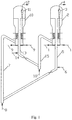
- the schematic flow chart of the process for preparing light olefins from methanol in this invention is as shown in Fig. 1 .
- Raw materials which are mainly methanol and/or dimethyl ether, are passed into the dense phase fluidized bed reactor (2) and are brought into contact with a catalyst to generate a gas phase product stream and a spent catalyst;
- the gas phase product stream and the entrained spent catalyst are passed into the cyclone separator (3), wherein the gas phase product stream is passed to a subsequent working section of separation via the outlet of the cyclone separator and the entrained spent catalyst is passed into the n th secondary reaction zone via the dipleg of the cyclone separator;
- the regenerated catalyst is passed into the dense phase fluidized bed reactor 2 via the stripper (13) and the lift pipe (15), and is sequentially passed through the 1 st to the n th secondary reaction zones to form a spent catalyst after carbon deposition; and the spent catalyst is then passed into the dense phase fluidized bed regenerator (10) via the stripper (5)
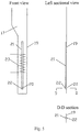
- the structural schematic diagram of the dense phase fluidized bed comprising 4 secondary regeneration zones in this invention is as shown in Fig. 3 , wherein the arrows in B-B sectional view show the flow directions of the catalyst between the secondary regeneration zones.
- 3 material flow controllers (17) and a baffle are vertically provided to separate the dense phase fluidized bed regeneration zone into 4 secondary regeneration zones. The catalyst is sequentially passed through the 1 st to the 4 th secondary regeneration zones and is then passed into the stripper.
- the structural schematic diagram of the strippers (5 and 13) in this invention is as shown in Fig. 4 .
- the opening on the pipe wall on the upper part of the stripper (5) is used as the material overflow port (18) between the n th secondary reaction zone and the stripper (5).
- the opening on the pipe wall on the upper part of the stripper (13) is used as the material overflow port (18) between the m th secondary regeneration zone and the stripper (13).
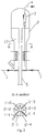
- the structural schematic diagram of the material flow controller in this invention is as shown in Fig. 5 .
- the material flow controller (17) is composed of a partition plate (19), an orifice (20), a material downward flow pipe (21), a bottom baffle (22), and a heat extraction member (23).
- the catalyst is passed into the material downward flow pipe from the top of the downward flow pipe, wherein the apparent gas linear velocity is less than or equal to the minimal fluidization speed, the catalyst in the material downward flow pipe is in a dense phase packing state, and a material flow driving force is formed to drive the catalyst to flow into a next secondary reaction zones (or regeneration zone) via the orifice.
- a coil structure may be used as the heat extraction member, which is fixed onto the partition plate.
- the apparent gas linear velocity in the dense phase fluidized bed reaction zone is 0.1-1.5 m/s; the apparent gas linear velocity in the dense phase fluidized bed regeneration zone is 0.1-1.5 m/s; the apparent gas linear velocity in the material flow controller is less than or equal to the minimal fluidization speed of the catalyst;
- the catalyst is preferably a catalyst comprising SAPO molecular sieve, and is further preferably a catalyst comprising SAPO-34 molecular sieve;
- a feed port is provided at the bottom of the reaction zone, and the feed comprises methanol and/or dimethyl ether, etc.;
- the stripping medium of the stripper (13) comprises water vapor;
- a regenerating medium inlet is provided at the bottom of the regeneration zone (10), and the regenerating medium comprises air, oxygen-depleted air, water vapor, etc.;
- the reaction zone (2) has a reaction temperature of 400-550°C and a bed layer density of 200-1200kg/m 3 , and the average amount of carbon deposition of the catalyst sequentially
- the object of controlling the amount of carbon deposition on catalyst, improving the uniformity of carbon content, and increasing the selectivity of light olefins can be achieved by using the method of this invention, which has relatively high technical advantages and can be used in the industrial production of light olefins.
- 4 secondary reaction zones were provided in the dense phase fluidized bed reactor, and 4 secondary regeneration zones were provided in the dense phase fluidized bed regenerator.
- Raw materials which were mainly methanol and/or dimethyl ether, were passed into the dense phase fluidized bed reactor and were brought into contact with a catalyst comprising SAPO-34 molecular sieve to generate a gas phase product stream and a spent catalyst.
- the gas phase material and the entrained spent catalyst were passed into the cyclone separator, wherein the gas phase product stream was passed to a subsequent working section of separation via the outlet of the cyclone separator and the entrained spent catalyst was passed into the 4 th secondary reaction zone via the dipleg of the cyclone separator.
- the regenerated catalyst was passed into the dense phase fluidized bed reactor via the stripper and the lift pipe, and was sequentially passed through the 1 st to the 4 th secondary reaction zones to form a spent catalyst after carbon deposition.
- the spent catalyst was then passed into the dense phase fluidized bed regenerator via the stripper and the lift pipe, and was sequentially passed through the 1 st to the 4 th secondary regeneration zones to form a regenerated catalyst after charking.
- the reaction conditions of the dense phase fluidized bed reactor were as follows: the reaction temperature was 400°C, the gas phase linear velocity was 0.3 m/s, the bed layer density was 1000kg/m 3 , the average amount of carbon deposition of the 1 st secondary reaction zone was 2wt%, the average amount of carbon deposition of the 2 nd secondary reaction zone was 6wt%, the average amount of carbon deposition of the 3 rd secondary reaction zone was 8wt%, and the average amount of carbon deposition of the 4 th secondary reaction zone was 10wt%.
- the reaction conditions of the dense phase fluidized bed regenerator were as follows: the reaction temperature was 500°C, the gas phase linear velocity was 0.3 m/s, the bed layer density was 1000kg/m 3 , the average amount of carbon deposition of the 1 st secondary regeneration zone was 7wt%, the average amount of carbon deposition of the 2 nd secondary regeneration zone was 4wt%, the average amount of carbon deposition of the 3 rd secondary regeneration zone was 2wt%, and the average amount of carbon deposition of the 4 th secondary regeneration zone was 1wt%.
- the reaction product was analyzed by online gas chromatography, and the carbon based yield of light olefins was 91.1 wt%.
- 3 secondary reaction zones were provided in the dense phase fluidized bed reactor, and 2 secondary regeneration zones were provided in the dense phase fluidized bed regenerator.
- Raw materials which were mainly methanol and/or dimethyl ether, were passed into the dense phase fluidized bed reactor and were brought into contact with a catalyst comprising SAPO-34 molecular sieve to generate a gas phase product stream and a spent catalyst.
- the gas phase material and the entrained spent catalyst were passed into the cyclone separator, wherein the gas phase product stream was passed to a subsequent working section of separation via the outlet of the cyclone separator and the entrained spent catalyst was passed into the 3 rd secondary reaction zone via the dipleg of the cyclone separator.
- the regenerated catalyst was passed into the dense phase fluidized bed reactor via the stripper and the lift pipe, and was sequentially passed through the 1 st to the 3 rd secondary reaction zones to form a spent catalyst after carbon deposition.
- the spent catalyst was then passed into the dense phase fluidized bed regenerator via the stripper and the lift pipe, and was sequentially passed through the 1 st to the 2 nd secondary regeneration zones to form a regenerated catalyst after charking.
- the reaction conditions of the dense phase fluidized bed reactor were as follows: the reaction temperature was 450°C, the gas phase linear velocity was 0.5 m/s, the bed layer density was 900kg/m 3 , the average amount of carbon deposition of the 1 st secondary reaction zone was 3wt%, the average amount of carbon deposition of the 2 nd secondary reaction zone was 7wt%, and the average amount of carbon deposition of the 3 rd secondary reaction zone was 9wt%.
- the reaction conditions of the dense phase fluidized bed regenerator were as follows: the reaction temperature was 600°C, the gas phase linear velocity was 0.7 m/s, the bed layer density was 700kg/m 3 , the average amount of carbon deposition of the 1 st secondary regeneration zone was 4wt%, and the average amount of carbon deposition of the 2 nd secondary regeneration zone was 2wt%.
- the reaction product was analyzed by online gas chromatography, and the carbon based yield of light olefins was 90.5 wt%.
- 6 secondary reaction zones were provided in the dense phase fluidized bed reactor, and 5 secondary regeneration zones were provided in the dense phase fluidized bed regenerator.
- Raw materials which were mainly methanol and/or dimethyl ether, were passed into the dense phase fluidized bed reactor and were brought into contact with a catalyst comprising SAPO-34 molecular sieve to generate a gas phase product stream and a spent catalyst.
- the gas phase material and the entrained spent catalyst were passed into the cyclone separator, wherein the gas phase product stream was passed to a subsequent working section of separation via the outlet of the cyclone separator and the entrained spent catalyst was passed into the 6 th secondary reaction zone via the dipleg of the cyclone separator.
- the regenerated catalyst was passed into the dense phase fluidized bed reactor via the stripper and the lift pipe, and was sequentially passed through the 1 st to the 6 th secondary reaction zones to form a spent catalyst after carbon deposition.
- the spent catalyst was then passed into the dense phase fluidized bed regenerator via the stripper and the lift pipe, and was sequentially passed through the 1 st to the 5 th secondary regeneration zones to form a regenerated catalyst after charking.
- the reaction conditions of the dense phase fluidized bed reactor were as follows: the reaction temperature was 480°C, the gas phase linear velocity was 0.7 m/s, the bed layer density was 700kg/m 3 , the average amount of carbon deposition of the 1 st secondary reaction zone was 1wt%, the average amount of carbon deposition of the 2 nd secondary reaction zone was 3wt%, the average amount of carbon deposition of the 3 rd secondary reaction zone was 4wt%, the average amount of carbon deposition of the 4 th secondary reaction zone was 5wt%, the average amount of carbon deposition of the 5 th secondary reaction zone was 6wt%, and the average amount of carbon deposition of the 6 th secondary reaction zone was 7wt%.
- the reaction conditions of the dense phase fluidized bed regenerator were as follows: the reaction temperature was 650°C, the gas phase linear velocity was 1.0 m/s, the bed layer density was 500kg/m 3 , the average amount of carbon deposition of the 1 st secondary regeneration zone was 5wt%, the average amount of carbon deposition of the 2 nd secondary regeneration zone was 3wt%, the average amount of carbon deposition of the 3 rd secondary regeneration zone was 2wt%, the average amount of carbon deposition of the 4 th secondary regeneration zone was 1wt%, and the average amount of carbon deposition of the 5 th secondary regeneration zone was 0.01wt%.
- the reaction product was analyzed by online gas chromatography, and the carbon based yield of light olefins was 91.4 wt%.
Description
- This invention relates to a reaction device for preparing light olefins from methanol and/or dimethyl ether.
- Light olefins, which are ethylene and propylene, are two important kinds of basic chemical raw materials, and the demand thereof is increasing. Generally, ethylene and propylene are produced via a petroleum scheme. However, the costs for producing ethylene and propylene from petroleum resources are increasing due to limited supply and relatively high price of petroleum resources. In recent years, techniques for preparing ethylene and propylene by converting substituent raw materials have been greatly developed. More attentions have been paid to the process of methanol-to-olefins (MTO), and the production scale on an order of million tons has been achieved. As the world economy develops, the demand for light olefins, particularly propylene, is increasing. It is reported as the analysis of CMAI Corporation that the demand for ethylene will increase at an average rate of 4.3% per year and the demand for propylene will increase at an average rate of 4.4% per year before 2016. Due to high-speed increase of the economy in China, all of the annual increase rates of the demand for ethylene and propylene in China exceed the average level of the world.
- In early 1980s, UCC Corporation successfully developed SAPO molecular sieves, wherein the SAPO-34 molecular sieve catalyst exhibits excellent catalytic performance when it is used in MTO reaction, and has very high selectivity for light olefins and very high activity. However, after the catalyst has been used for a period of time, the activity is lost due to carbon deposition. A remarkable induction period is present in the use of the SAPO-34 molecular sieve catalyst. In the induction period, the selectivity for olefins is relatively low and the selectivity for alkanes is relatively high. As the reaction time increases, the selectivity for light olefins gradually increases. After the induction period, the catalyst maintains high selectivity and high activity in a certain period of time. With the subsequent elongation of the time, the activity of the catalyst rapidly decreases.
-
US6166282 discloses a technique and a reactor for converting methanol to light olefins, which use a fast fluidized bed reactor, wherein after the completion of a reaction in a dense phase reaction zone having a relatively low gas speed, a gas phase rises to a fast separation zone having an inner diameter which rapidly becomes smaller, and most of the entrained catalyst is preliminarily separated using a special gas-solid separation apparatus. Since the product gas and the catalyst are rapidly separated after reaction, a secondary reaction is effectively prevented. Upon analog computation, the inner diameter of the fast fluidized bed reactor and the storage amount of the catalyst required are both greatly reduced, compared to the conventional bubbling fluidized bed reactors. However, the carbon based yields of light olefins in this method are all typically about 77%, and there are problems concerning relatively low yields of light olefins. -
CN101402538B discloses a method for increasing the yield of light olefins. This method provides a second reaction zone on the upper part of a first reaction zone for converting methanol to light olefins, and the diameter of the second reaction zone is greater than that of the first reaction zone to increase the residence time of the product gas from the outlet of the first reaction zone in the second reaction zone, such that the unreacted methanol, the generated dimethyl ether, and hydrocarbons having 4 or more carbons continue react so as to achieve the object of increasing the yield of light olefins. This method may increase the yield of light olefins to some extent. However, since the catalyst from the first reaction zone has already carried a lot of deposited carbon and relatively high catalyst activity is required to crack hydrocarbons having 4 or more carbons, the conversion efficiencies of hydrocarbons having 4 or more carbons in the second reaction zone in this method are still slightly low, such that the yield of light olefins is slightly low. -
CN102276406A discloses a method for increasing the production of propylene. This technique provides three reaction zones, wherein a first rapid bed reaction zone is used for converting methanol to olefins, and a lift pipe reaction zone and a second rapid bed reaction zone are connected in series to convert ethylene, hydrocarbons having 4 or more carbons, and unreacted methanol or dimethyl ether. In this patent, the residence time of substances, such as hydrocarbons having 4 or more carbons, etc., in the reaction zone and the second rapid bed reaction zone is relatively short and the conversion efficiency is relatively low, such that the yield of propylene is slightly low. -
CN102875289A discloses a fluidized bed reaction device with a lift pipe reactor arranged therein, which is used for increasing the yield of light olefins. A first raw material is passed into a fluidized bed reaction zone and is brought into contact with a catalyst to generate a product comprising light olefins, and at the meanwhile a spent catalyst is formed; a part of the spent catalyst is passed into a regenerator for regeneration to form a regenerated catalyst, and the other part of the spent catalyst is passed into a lift pipe with an outlet end located in the reaction zone and is brought into contact with a second raw material so as to lift the spent catalyst into the reaction zone; and the regenerated catalyst is returned to the reaction zone of the fluidized bed reactor. Since the reaction device disclosed in this patent does not comprises a stripping portion, the spent catalyst will be passed into the regenerator with carrying a part of the product gas and is combusted with oxygen to reduce the yield of light olefins. - The technique for preparing olefins from methanol disclosed in
CN102875296A provides three reaction zones, which are a rapid bed, a downer, and a lift pipe. Since the catalyst is circulated among the regenerator, the rapid bed, the lift pipe, and the downer, the flow direction is extremely complex, the distribution and the control of the flow rate are extremely difficult, and the activity of catalyst greatly changes. - As well known in the art, the selectivity for light olefins is closely associated with the amount of carbon deposition on the catalyst. A certain amount of carbon deposition on SAPO-34 catalyst is needed to ensure a high selectivity for light olefins. Main reactors used in current MTO process are fluidized beds. The fluidized bed is close to a continuously stirred tank reactor, which has wide a distribution of carbon deposition on catalyst and is not advantageous for increasing the selectivity for light olefins. Since the catalyst-to-alcohol ratio is very small and the coke yield rate is relatively low in the MTO process, in order to achieve a lager and controllable catalyst circulation volume, it is required to control the amount of carbon deposition and the uniformity of carbon content on the catalyst in the regeneration zone to certain levels. Therefore, the object of controlling the amount of carbon deposition and the uniformity of carbon content on the catalyst in the reaction zone is achieved. Therefore, it is a key technique in the MTO process to control the amount of carbon deposition and the uniformity of carbon content of the catalyst in the reaction zone to certain levels.
- In order to solve the problems described above, a few researchers propose the techniques, such as providing an upper and a lower reaction zones in a fluidized bed, two fluidized beds connected in series, and a fluidized bed, a lift pipe, and a downer connected in series, etc. E.g.,
US 2 919 231 A describes such a hybrid reactor arrangement, which comprises a dense phase fluidized bed reactor, a cyclone separator, a stripper and a lift pipe. These preliminarily disclose methods for controlling the amount of carbon deposition and the uniformity of carbon content of the catalyst, and certain advantageous effects have been obtained. However, the complexity and the controlling difficulty of the MTO process are increased at the meanwhile. This invention proposes a solution of forming a plurality of secondary reaction zones (regeneration zones) by providing inner members in a dense phase fluidized bed to solve the problems of controlling the amount of carbon deposition and the uniformity of carbon content of the catalyst so as to increase the selectivity of light olefins. - The technical problem to be solved by this invention is the problem that the selectivity for light olefins in the prior art is not high present, and provides a new reaction device with the selectivity of light olefins increased. This reaction device is used in the production of light olefins, and has the advantages of good carbon deposition uniformity of catalyst, relatively high yield of light olefins, and good economical efficiency of the production process of light olefins.
- In order to solve the problems described above, this invention provides a reaction device for preparing light olefins from methanol and/or dimethyl ether, comprising a dense phase fluidized bed reactor (2), a cyclone separator (3), a stripper (5), a lift pipe (7), a dense phase fluidized bed regenerator (10), a cyclone separator (11), a stripper (13), and a lift pipe (15); wherein a feeding line for reactor (1) is connected to the bottom of the dense phase fluidized bed reactor (2); a part of the stripper (5) is in the dense phase fluidized bed reactor (2), and the remaining part thereof is below the dense phase fluidized bed reactor (2); the bottom of the lift pipe (7) is connected to the bottom of the stripper (5), and the top of the lift pipe (7) is connected to the dense phase fluidized bed regenerator (10); a feeding line for regenerator (9) is connected to the bottom of the dense phase fluidized bed regenerator (10); a part of the stripper (13) is in the dense phase fluidized bed regenerator (10), and the remaining part thereof is below the dense phase fluidized bed regenerator (10); the bottom of the lift pipe (15) is connected to the bottom of the stripper (13), and the top of the lift pipe (15) is connected to the dense phase fluidized bed reactor (2), characterized in that a material flow controller (17) is provided in the dense phase fluidized bed reactor (2) and/or the dense phase fluidized bed regenerator (10), and the dense phase fluidized bed reactor (2) is separated into n secondary reaction zones by the material flow controller (17) and the 1st to the nth secondary reaction zones are sequentially connected; the dense phase fluidized bed regenerator (10) is separated into m secondary regeneration zones by the material flow controller (17) and the 1st to the mth secondary regeneration zones are sequentially connected; and wherein n≥2, and m ≥2,, wherein the material flow controller (17) is composed of a partition plate (19), an orifice (20), a material downward flow pipe (21), a bottom baffle (22), and a heat extraction member (23); and the orifice (20) is located below the partition plate (19) and is connected to the bottom of the material downward flow pipe (21), the bottom baffle (22) is located at the bottom of the material downward flow pipe (21) and the orifice (20), and the heat extraction member (23) is fixed on the partition plate (19).
- In one preferred embodiment, the top of the lift pipe (15) is connected to the 1st secondary reaction zone, the nth secondary reaction zone is connected to a material overflow port (18) on the upper part of the stripper (5); and the cyclone separator (3) is provided on the upper part of the dense phase fluidized bed reactor (2), a top outlet of the cyclone separator (3) is connected to a product material line (4), and the bottom of the cyclone separator (3) is connected to the nth secondary reaction zone.
- In one preferred embodiment, the top of the lift pipe (7) is connected to the 1st secondary regeneration zone, the mth secondary regeneration zone is connected to a material overflow port (18) on the upper part of the stripper (13); and the cyclone separator (11) is provided on the upper part of the dense phase fluidized bed regenerator (10), a top outlet of the cyclone separator (11) is connected to an exhaust gas line (12), and the bottom of the cyclone separator (11) is connected to the mth secondary regeneration zone.
- In one preferred embodiment, 8≥n≥3.
- In one preferred embodiment, 8≥m≥3.
- In one preferred embodiment, the bottom baffle (22) is a porous plate or a nonporous plate.
- Compared to solutions in the prior art, the advantageous effects of this invention include but are not limited to the following aspects:
- (1) The dense phase fluidized bed has a relatively high density of bed layer, a relatively low catalyst rate, and a low abrasion.
- (2) The gas speed in the material downward flow pipe of the material flow controller is less than or equal to the minimal fluidization speed of the catalyst and the catalyst is in a dense phase packing state, such that a unidirectional dense phase conveying stream of the catalyst is formed, the backmixing of catalyst between adjacent secondary reaction zones (or adjacent secondary regeneration zones) is prevented, and the distribution of residence time is narrow.
- (3) The heat extraction member in the material flow controller has an effect of controlling the temperature of the reaction zone.
- (4) The reaction zone is separated into n secondary reaction zones by the material flow controller and the catalyst sequentially passes through the 1st secondary reaction zone to the nth secondary reaction zone, such that the distribution of residence time is narrow and the uniformity of carbon content of the spent catalyst is greatly increased.
- (5) The regeneration zone is separated into m secondary regeneration zones by the material flow controller and the catalyst sequentially passes through the 1st secondary regeneration zone to the mth secondary regeneration zone, such that the distribution of residence time is narrow and the uniformity of carbon content of the regenerated catalyst is greatly increased.
- (6) Relatively precise control of carbon content of the regenerated catalyst and the spent catalyst is achieved, the distribution of carbon content is relatively uniform, the selectivity for light olefins is increased, and the carbon content may be regulated as needed to optimize the ratio of propylene/ethylene.
- (7) Since the distribution of carbon content of the catalyst is relatively uniform, the storage amount of the catalyst required in the reaction zone decreases.
- (8) The configuration of a plurality of secondary reaction zones facilitates the achievement of large-scale reactors.
-
-
Fig. 1 shows a schematic flow chart of the method in this invention; -
Fig. 2 shows a structural schematic diagram of the dense phase fluidized bed comprising 4 secondary reaction zones in this invention, wherein the arrows in A-A sectional view show the flow directions of the catalyst between the secondary reaction zones; -
Fig. 3 shows a structural schematic diagram of the dense phase fluidized bed comprising 4 secondary regeneration zones in this invention, wherein the arrows in B-B sectional view show the flow directions of the catalyst between the secondary regeneration zones; -
Fig. 4 shows a structural schematic diagram of the stripper in this invention; and -
Fig. 5 shows a structural schematic diagram of the material flow controller in this invention. - Reference numerals in the accompanying drawings are described as follows:
- 1 - feeding line for reactor; 1-1 1st secondary reaction zone feed branch line; 1-2 2nd secondary reaction zone feed branch line; 1-3 3rd secondary reaction zone feed branch line; 1-4 4th secondary reaction zone feed branch line; 2 - dense phase fluidized bed reactor; 2-1 1st secondary reaction zone; 2-2 2nd secondary reaction zone; 2-3 3rd secondary reaction zone; 2-4 4th secondary reaction zone; 3 - cyclone separator; 4 - product material line; 5 - stripper; 6 - water vapor line; 7 - lift pipe; 8 - lift gas line; 9 - feeding line for regenerator; 9-1 1st secondary regeneration zone feed branch line; 9-2 2nd secondary regeneration zone feed branch line; 9-3 3rd secondary regeneration zone feed branch line; 9-4 4th secondary regeneration zone feed branch line; 10 - dense phase fluidized bed regenerator; 10-1 1st secondary regeneration zone; 10-2 2nd secondary regeneration zone; 10-3 3rd secondary regeneration zone; 10-4 4th secondary regeneration zone; 11 - cyclone separator; 12 - exhaust gas line; 13 - stripper; 14 - water vapor line; 15 - lift pipe; 16 - lift gas line; 17 - material flow controller; 18 - material overflow port; 19 - partition plate; 20 - orifice; 21 - material downward flow pipe; 22 - bottom baffle; 23 - heat extraction member.
- In order to increase the selectivity for light olefins in the process of preparing light olefins from oxygen-containing compounds, this invention provides a reaction device for preparing light olefins from methanol and/or dimethyl ether, which mainly comprises a dense phase fluidized bed reactor (2), a cyclone separator (3), a stripper (5), a lift pipe (7), a dense phase fluidized bed regenerator (10), a cyclone separator (11), a stripper (13), and a lift pipe (15). A feeding line for reactor (1) is connected to the bottom of the dense phase fluidized bed reactor (2). A part of the stripper (5) is in the dense phase fluidized bed reactor (2), and the remaining part thereof is located below the dense phase fluidized bed reactor (2). The water vapor line (6) is connected to the bottom of the stripper (5). The bottom of the lift pipe (7) is connected to the bottom of the stripper (5). The lift gas line (8) is connected to the bottom of the lift pipe (7). The top of the lift pipe 7 is connected to the dense phase fluidized bed regenerator (10). The feeding line for regenerator (9) is connected to the bottom of the dense phase fluidized bed regenerator (10). Apart of the stripper (13) is in the dense phase fluidized bed regenerator (10), and the remaining part thereof is located below the dense phase fluidized bed regenerator (10). The water vapor line (14) is connected to the bottom of the stripper (13). The bottom of the lift pipe (15) is connected to the bottom of the stripper (13). The lift gas line (16) is connected to the bottom of the lift pipe (15). The top of the lift pipe (15) is connected to the dense phase fluidized bed reactor (2). Preferably, the feeding line for reactor (1) comprises n reaction zone feed branch lines (1-1, ......, 1-n), the dense phase fluidized bed reactor (2) is separated into n secondary reaction zones (2-1, ......, 2-n) by a material flow controller (17), wherein n≥2 and preferably 8≥n≥3; n reaction zone feed branch lines are connected to n secondary reaction zones, respectively; and the 1st to the nth secondary reaction zones are sequentially connected, the top of the lift pipe (15) is connected to the 1st secondary reaction zone, the nth secondary reaction zone is connected to a material overflow port (18) on the upper part of the stripper (5), a cyclone separator (3) is provided on the upper part of the dense phase fluidized bed reactor (2), a top outlet of the cyclone separator (3) is connected to a product material line (4), and the bottom of the cyclone separator (3) is connected to the nth secondary reaction zone.
- Preferably, the feeding line for regenerator (9) comprises m regeneration zone feed branch lines (9-1, ......, 9-n), the dense phase fluidized bed regenerator (10) is separated into m secondary regeneration zones (10-1, ......, 10-n) by the material flow controller (17), wherein m≥2 and preferably 8≥m≥3; m regeneration zone feed branch lines are connected to m secondary regeneration zones, respectively; and the 1st to the mth secondary regeneration zones are sequentially connected, the top of the lift pipe (7) is connected to the 1st secondary regeneration zone, the mth secondary regeneration zone is connected to a material overflow port (18) on the upper part of the stripper (13), a cyclone separator (11) is provided on the upper part of the dense phase fluidized bed regenerator (10), a top outlet of the cyclone separator (11) is connected to an exhaust gas line (12), and the bottom of the cyclone separator (11) is connected to the mth secondary regeneration zone.
- The material flow controller (17) of the inventive reaction device is composed of a partition plate (19), an orifice (20), a material downward flow pipe (21), a bottom baffle (22), and a heat extraction member (23). The orifice (20) is located below the partition plate (19) and is connected to the bottom of the material downward flow pipe (21), a porous plate or a nonporous plate may be used as the bottom baffle (22), which is located at the bottom of the material downward flow pipe (21) and the orifice (20), and the heat extraction member (23) is fixed on the partition plate (19).
- In one preferred embodiment, the schematic flow chart of the process for preparing light olefins from methanol in this invention is as shown in
Fig. 1 . Raw materials, which are mainly methanol and/or dimethyl ether, are passed into the dense phase fluidized bed reactor (2) and are brought into contact with a catalyst to generate a gas phase product stream and a spent catalyst; the gas phase product stream and the entrained spent catalyst are passed into the cyclone separator (3), wherein the gas phase product stream is passed to a subsequent working section of separation via the outlet of the cyclone separator and the entrained spent catalyst is passed into the nth secondary reaction zone via the dipleg of the cyclone separator; the regenerated catalyst is passed into the dense phase fluidized bed reactor 2 via the stripper (13) and the lift pipe (15), and is sequentially passed through the 1st to the nth secondary reaction zones to form a spent catalyst after carbon deposition; and the spent catalyst is then passed into the dense phase fluidized bed regenerator (10) via the stripper (5) and the lift pipe (7), and is sequentially passed through the 1st to the mth secondary regeneration zones to form a regenerated catalyst after charking. The catalyst is preferably a catalyst comprising SAPO molecular sieve, and is further preferably a catalyst comprising SAPO-34 molecular sieve. - In a specific embodiment, the structural schematic diagram of the dense phase fluidized bed comprising 4 secondary reaction zones in this invention is as shown in
Fig. 2 , wherein the arrows in A-A sectional view show the flow directions of the catalyst between the secondary reaction zones. 3 material flow controllers (17) and a baffle are vertically provided to separate the dense phase fluidized bed reaction zone into 4 secondary reaction zones. The catalyst is sequentially passed through the 1st to the 4th secondary reaction zones and is then passed into the stripper. - In a specific embodiment, the structural schematic diagram of the dense phase fluidized bed comprising 4 secondary regeneration zones in this invention is as shown in
Fig. 3 , wherein the arrows in B-B sectional view show the flow directions of the catalyst between the secondary regeneration zones. 3 material flow controllers (17) and a baffle are vertically provided to separate the dense phase fluidized bed regeneration zone into 4 secondary regeneration zones. The catalyst is sequentially passed through the 1st to the 4th secondary regeneration zones and is then passed into the stripper. - Preferably, the structural schematic diagram of the strippers (5 and 13) in this invention is as shown in
Fig. 4 . The opening on the pipe wall on the upper part of the stripper (5) is used as the material overflow port (18) between the nth secondary reaction zone and the stripper (5). The opening on the pipe wall on the upper part of the stripper (13) is used as the material overflow port (18) between the mth secondary regeneration zone and the stripper (13). - Preferably, the structural schematic diagram of the material flow controller in this invention is as shown in
Fig. 5 . The material flow controller (17) is composed of a partition plate (19), an orifice (20), a material downward flow pipe (21), a bottom baffle (22), and a heat extraction member (23). The catalyst is passed into the material downward flow pipe from the top of the downward flow pipe, wherein the apparent gas linear velocity is less than or equal to the minimal fluidization speed, the catalyst in the material downward flow pipe is in a dense phase packing state, and a material flow driving force is formed to drive the catalyst to flow into a next secondary reaction zones (or regeneration zone) via the orifice. A coil structure may be used as the heat extraction member, which is fixed onto the partition plate. - Preferably, the apparent gas linear velocity in the dense phase fluidized bed reaction zone is 0.1-1.5 m/s; the apparent gas linear velocity in the dense phase fluidized bed regeneration zone is 0.1-1.5 m/s; the apparent gas linear velocity in the material flow controller is less than or equal to the minimal fluidization speed of the catalyst; the catalyst is preferably a catalyst comprising SAPO molecular sieve, and is further preferably a catalyst comprising SAPO-34 molecular sieve; a feed port is provided at the bottom of the reaction zone, and the feed comprises methanol and/or dimethyl ether, etc.; the stripping medium of the stripper (13) comprises water vapor; a regenerating medium inlet is provided at the bottom of the regeneration zone (10), and the regenerating medium comprises air, oxygen-depleted air, water vapor, etc.; the reaction zone (2) has a reaction temperature of 400-550°C and a bed layer density of 200-1200kg/m3, and the average amount of carbon deposition of the catalyst sequentially increases from the 1st secondary reaction zone to the nth secondary reaction zone, wherein the average amount of carbon deposition of the 1st secondary reaction zone is 0.5-3wt% and the average amount of carbon deposition of the nth secondary reaction zone is 7-10wt%; and the regeneration zone (10) has a reaction temperature of 500-700°C and a bed layer density of 200-1200kg/m3, and the average amount of carbon deposition of the catalyst sequentially decreases from the 1st secondary regeneration zone to the mth secondary regeneration zone, wherein the average amount of carbon deposition of the 1st secondary regeneration zone is 3-10wt% and the average amount of carbon deposition of the mth secondary regeneration zone is 0-3wt%. The object of controlling the amount of carbon deposition on catalyst, improving the uniformity of carbon content, and increasing the selectivity of light olefins can be achieved by using the method of this invention, which has relatively high technical advantages and can be used in the industrial production of light olefins.
- In order to better illustrate this invention and facilitate the understanding of the technical solution of this invention, typical and non-limiting Examples of this invention are as follows.
- 4 secondary reaction zones were provided in the dense phase fluidized bed reactor, and 4 secondary regeneration zones were provided in the dense phase fluidized bed regenerator. Raw materials, which were mainly methanol and/or dimethyl ether, were passed into the dense phase fluidized bed reactor and were brought into contact with a catalyst comprising SAPO-34 molecular sieve to generate a gas phase product stream and a spent catalyst. The gas phase material and the entrained spent catalyst were passed into the cyclone separator, wherein the gas phase product stream was passed to a subsequent working section of separation via the outlet of the cyclone separator and the entrained spent catalyst was passed into the 4th secondary reaction zone via the dipleg of the cyclone separator. The regenerated catalyst was passed into the dense phase fluidized bed reactor via the stripper and the lift pipe, and was sequentially passed through the 1st to the 4th secondary reaction zones to form a spent catalyst after carbon deposition. The spent catalyst was then passed into the dense phase fluidized bed regenerator via the stripper and the lift pipe, and was sequentially passed through the 1st to the 4th secondary regeneration zones to form a regenerated catalyst after charking. The reaction conditions of the dense phase fluidized bed reactor were as follows: the reaction temperature was 400°C, the gas phase linear velocity was 0.3 m/s, the bed layer density was 1000kg/m3, the average amount of carbon deposition of the 1st secondary reaction zone was 2wt%, the average amount of carbon deposition of the 2nd secondary reaction zone was 6wt%, the average amount of carbon deposition of the 3rd secondary reaction zone was 8wt%, and the average amount of carbon deposition of the 4th secondary reaction zone was 10wt%. The reaction conditions of the dense phase fluidized bed regenerator were as follows: the reaction temperature was 500°C, the gas phase linear velocity was 0.3 m/s, the bed layer density was 1000kg/m3, the average amount of carbon deposition of the 1st secondary regeneration zone was 7wt%, the average amount of carbon deposition of the 2nd secondary regeneration zone was 4wt%, the average amount of carbon deposition of the 3rd secondary regeneration zone was 2wt%, and the average amount of carbon deposition of the 4th secondary regeneration zone was 1wt%. The reaction product was analyzed by online gas chromatography, and the carbon based yield of light olefins was 91.1 wt%.
- 3 secondary reaction zones were provided in the dense phase fluidized bed reactor, and 2 secondary regeneration zones were provided in the dense phase fluidized bed regenerator. Raw materials, which were mainly methanol and/or dimethyl ether, were passed into the dense phase fluidized bed reactor and were brought into contact with a catalyst comprising SAPO-34 molecular sieve to generate a gas phase product stream and a spent catalyst. The gas phase material and the entrained spent catalyst were passed into the cyclone separator, wherein the gas phase product stream was passed to a subsequent working section of separation via the outlet of the cyclone separator and the entrained spent catalyst was passed into the 3rd secondary reaction zone via the dipleg of the cyclone separator. The regenerated catalyst was passed into the dense phase fluidized bed reactor via the stripper and the lift pipe, and was sequentially passed through the 1st to the 3rd secondary reaction zones to form a spent catalyst after carbon deposition. The spent catalyst was then passed into the dense phase fluidized bed regenerator via the stripper and the lift pipe, and was sequentially passed through the 1st to the 2nd secondary regeneration zones to form a regenerated catalyst after charking. The reaction conditions of the dense phase fluidized bed reactor were as follows: the reaction temperature was 450°C, the gas phase linear velocity was 0.5 m/s, the bed layer density was 900kg/m3, the average amount of carbon deposition of the 1st secondary reaction zone was 3wt%, the average amount of carbon deposition of the 2nd secondary reaction zone was 7wt%, and the average amount of carbon deposition of the 3rd secondary reaction zone was 9wt%. The reaction conditions of the dense phase fluidized bed regenerator were as follows: the reaction temperature was 600°C, the gas phase linear velocity was 0.7 m/s, the bed layer density was 700kg/m3, the average amount of carbon deposition of the 1st secondary regeneration zone was 4wt%, and the average amount of carbon deposition of the 2nd secondary regeneration zone was 2wt%. The reaction product was analyzed by online gas chromatography, and the carbon based yield of light olefins was 90.5 wt%.
- 6 secondary reaction zones were provided in the dense phase fluidized bed reactor, and 5 secondary regeneration zones were provided in the dense phase fluidized bed regenerator. Raw materials, which were mainly methanol and/or dimethyl ether, were passed into the dense phase fluidized bed reactor and were brought into contact with a catalyst comprising SAPO-34 molecular sieve to generate a gas phase product stream and a spent catalyst. The gas phase material and the entrained spent catalyst were passed into the cyclone separator, wherein the gas phase product stream was passed to a subsequent working section of separation via the outlet of the cyclone separator and the entrained spent catalyst was passed into the 6th secondary reaction zone via the dipleg of the cyclone separator. The regenerated catalyst was passed into the dense phase fluidized bed reactor via the stripper and the lift pipe, and was sequentially passed through the 1st to the 6th secondary reaction zones to form a spent catalyst after carbon deposition. The spent catalyst was then passed into the dense phase fluidized bed regenerator via the stripper and the lift pipe, and was sequentially passed through the 1st to the 5th secondary regeneration zones to form a regenerated catalyst after charking. The reaction conditions of the dense phase fluidized bed reactor were as follows: the reaction temperature was 480°C, the gas phase linear velocity was 0.7 m/s, the bed layer density was 700kg/m3, the average amount of carbon deposition of the 1st secondary reaction zone was 1wt%, the average amount of carbon deposition of the 2nd secondary reaction zone was 3wt%, the average amount of carbon deposition of the 3rd secondary reaction zone was 4wt%, the average amount of carbon deposition of the 4th secondary reaction zone was 5wt%, the average amount of carbon deposition of the 5th secondary reaction zone was 6wt%, and the average amount of carbon deposition of the 6th secondary reaction zone was 7wt%. The reaction conditions of the dense phase fluidized bed regenerator were as follows: the reaction temperature was 650°C, the gas phase linear velocity was 1.0 m/s, the bed layer density was 500kg/m3, the average amount of carbon deposition of the 1st secondary regeneration zone was 5wt%, the average amount of carbon deposition of the 2nd secondary regeneration zone was 3wt%, the average amount of carbon deposition of the 3rd secondary regeneration zone was 2wt%, the average amount of carbon deposition of the 4th secondary regeneration zone was 1wt%, and the average amount of carbon deposition of the 5th secondary regeneration zone was 0.01wt%. The reaction product was analyzed by online gas chromatography, and the carbon based yield of light olefins was 91.4 wt%.
- This invention has been described in detail above, but this invention is not limited to specific embodiments described herein. It is to be understood by the person skilled in the art that other modifications and variations can be made without departing from the scope of the invention. The scope of the invention is defined by the appended claims.
Claims (6)
- A reaction device for preparing light olefins from methanol and/or dimethyl ether, wherein the reaction device comprises a dense phase fluidized bed reactor (2), a cyclone separator (3), a stripper (5), a lift pipe (7), a dense phase fluidized bed regenerator (10), a cyclone separator (11), a stripper (13), and a lift pipe (15); wherein a feeding line for reactor (1) is connected to the bottom of the dense phase fluidized bed reactor (2); a part of the stripper (5) is in the dense phase fluidized bed reactor (2), and the remaining part thereof is below the dense phase fluidized bed reactor (2); the bottom of the lift pipe (7) is connected to the bottom of the stripper (5), and the top of the lift pipe (7) is connected to the dense phase fluidized bed regenerator (10); a feeding line for regenerator (9) is connected to the bottom of the dense phase fluidized bed regenerator (10); a part of the stripper (13) is in the dense phase fluidized bed regenerator (10), and the remaining part thereof is below the dense phase fluidized bed regenerator (10); the bottom of the lift pipe (15) is connected to the bottom of the stripper (13), and the top of the lift pipe (15) is connected to the dense phase fluidized bed reactor (2), wherein a material flow controller (17) is provided in the dense phase fluidized bed reactor (2) and/or the dense phase fluidized bed regenerator (10), and the dense phase fluidized bed reactor (2) is separated into n secondary reaction zones by the material flow controller (17) and the 1st to the nth secondary reaction zones are sequentially connected; the dense phase fluidized bed regenerator (10) is separated into m secondary regeneration zones by the material flow controller (17) and the 1st to the mth secondary regeneration zones are sequentially connected; and wherein n≥2, and m≥2, wherein the material flow controller (17) is composed of a partition plate (19), an orifice (20), a material downward flow pipe (21), a bottom baffle (22), and a heat extraction member (23); and the orifice (20) is located below the partition plate (19) and is connected to the bottom of the material downward flow pipe (21), the bottom baffle (22) is located at the bottom of the material downward flow pipe (21) and the orifice (20), and the heat extraction member (23) is fixed on the partition plate (19).
- The reaction device according to claim 1, characterized in that the top of the lift pipe (15) is connected to the 1st secondary reaction zone, the nth secondary reaction zone is connected to a material overflow port (18) on the upper part of the stripper (5); and the cyclone separator (3) is provided on the upper part of the dense phase fluidized bed reactor (2), a top outlet of the cyclone separator (3) is connected to a product material line (4), and the bottom of the cyclone separator (3) is connected to the nth secondary reaction zone.
- The reaction device according to claim 1, characterized in that the top of the lift pipe (7) is connected to the 1st secondary regeneration zone, the mth secondary regeneration zone is connected to a material overflow port (18) on the upper part of the stripper (13); and the cyclone separator (11) is provided on the upper part of the dense phase fluidized bed regenerator (10), a top outlet of the cyclone separator (11) is connected to an exhaust gas line (12), and the bottom of the cyclone separator (11) is connected to the mth secondary regeneration zone.
- The reaction device according to claim 1, characterized in that 8≥n≥3.
- The reaction device according to claim 1, characterized in that 8≥m≥3.
- The reaction device according to claim 1, characterized in that the bottom baffle (22) is a porous plate or a nonporous plate.
Applications Claiming Priority (1)
| Application Number | Priority Date | Filing Date | Title |
|---|---|---|---|
| PCT/CN2013/088413 WO2015081494A1 (en) | 2013-12-03 | 2013-12-03 | Reaction device for preparing light olefins from methanol and/or dimethyl ether |
Publications (3)
| Publication Number | Publication Date |
|---|---|
| EP3078414A1 EP3078414A1 (en) | 2016-10-12 |
| EP3078414A4 EP3078414A4 (en) | 2017-06-07 |
| EP3078414B1 true EP3078414B1 (en) | 2018-09-19 |
Family
ID=53272726
Family Applications (1)
| Application Number | Title | Priority Date | Filing Date |
|---|---|---|---|
| EP13898849.8A Active EP3078414B1 (en) | 2013-12-03 | 2013-12-03 | Reaction device for preparing light olefins from methanol and/or dimethyl ether |
Country Status (10)
| Country | Link |
|---|---|
| US (1) | US9827544B2 (en) |
| EP (1) | EP3078414B1 (en) |
| JP (1) | JP6230722B2 (en) |
| KR (1) | KR101763864B1 (en) |
| AU (1) | AU2013407185B2 (en) |
| BR (1) | BR112016012613B1 (en) |
| DK (1) | DK3078414T3 (en) |
| RU (1) | RU2636077C1 (en) |
| SG (1) | SG11201604419XA (en) |
| WO (1) | WO2015081494A1 (en) |
Families Citing this family (15)
| Publication number | Priority date | Publication date | Assignee | Title |
|---|---|---|---|---|
| FR3029979B1 (en) * | 2014-12-12 | 2019-04-05 | IFP Energies Nouvelles | METHOD AND INSTALLATION OF COMBUSTION BY OXYDO-CHEMICAL LOOP REDUCTION OF A GAS HYDROCARBONATED LOAD WITH IN SITU CATALYTIC REFORMING OF THE LOAD |
| US10710940B2 (en) * | 2016-10-19 | 2020-07-14 | Dalian Institute Of Chemical Physics, Chinese Academy Of Sciences | Turbulent fluidized-bed reactor, device, and method using oxygen-containing compound for manufacturing propene and C4 hydrocarbon |
| JP6883099B2 (en) * | 2016-10-19 | 2021-06-09 | 中国科学院大▲連▼化学物理研究所Dalian Institute Of Chemical Physics,Chinese Academy Of Sciences | Method for Producing Hydrocarbons of Propylene and C4 and its Equipment |
| BR112019008066B1 (en) * | 2016-10-19 | 2022-03-22 | Dalian Institute Of Chemical Physics, Chinese Academy Of Sciences | Fast fluidized bed reactor, device and method for manufacturing propylene or c4 hydrocarbons using an oxygen-containing compound |
| WO2018072140A1 (en) * | 2016-10-19 | 2018-04-26 | 中国科学院大连化学物理研究所 | Method and device for manufacturing propene and c4 hydrocarbon |
| CN108017496B (en) * | 2016-11-04 | 2021-03-30 | 中国石油化工股份有限公司 | Apparatus for producing olefins and aromatic hydrocarbons and method thereof |
| CN108786669B (en) * | 2017-04-27 | 2021-01-12 | 中国科学院大连化学物理研究所 | Fluidized bed gas distributor, reactor using same and method for co-producing p-xylene and low-carbon olefin |
| CN108794294B (en) * | 2017-04-27 | 2020-12-11 | 中国科学院大连化学物理研究所 | Fluidized bed gas distributor, reactor using same and method for co-producing p-xylene and low-carbon olefin |
| CN108786670B (en) | 2017-04-27 | 2021-01-26 | 中国科学院大连化学物理研究所 | Method for preparing p-xylene and co-producing low-carbon olefin by methanol and/or dimethyl ether and toluene |
| CN108786671B (en) * | 2017-04-27 | 2021-04-23 | 中国科学院大连化学物理研究所 | Fluidized bed device and method for preparing p-xylene and co-producing low-carbon olefin by methanol and/or dimethyl ether and benzene |
| CN108786672B (en) | 2017-04-27 | 2021-01-26 | 中国科学院大连化学物理研究所 | Method for preparing p-xylene and co-producing low-carbon olefin by using methanol and/or dimethyl ether and benzene |
| CN108794291B (en) * | 2017-04-27 | 2020-11-27 | 中国科学院大连化学物理研究所 | Fluidized bed device and method for preparing p-xylene and co-producing low-carbon olefin by methanol and/or dimethyl ether and toluene |
| US11833502B2 (en) | 2020-10-16 | 2023-12-05 | Dalian Institute Of Chemical Physics, Chinese Academy Of Sciences | Coke control reactor, and device and method for preparing low-carbon olefins from oxygen-containing compound |
| WO2022077454A1 (en) | 2020-10-16 | 2022-04-21 | 中国科学院大连化学物理研究所 | Fluidized bed reactor, device, and application |
| US20230125888A1 (en) | 2020-10-16 | 2023-04-27 | Dalian Institute Of Chemical Physics, Chinese Academy Of Sciences | Regeneration device, device for preparing low-carbon olefins, and use thereof |
Family Cites Families (33)
| Publication number | Priority date | Publication date | Assignee | Title |
|---|---|---|---|---|
| US2919241A (en) * | 1955-06-17 | 1959-12-29 | Kellogg M W Co | Conversion process and apparatus with plural adjacent stages and central stripping zone |
| US3904548A (en) * | 1973-09-10 | 1975-09-09 | Mobil Oil Corp | Regenerating catalyst with tangential introduction and circumferential swirl in a fluidized bed |
| GB1562571A (en) * | 1978-01-26 | 1980-03-12 | Melik Akhnazarov | Others regeneration of hydrocarbon cracking catalyst |
| FR2417336A1 (en) * | 1978-02-16 | 1979-09-14 | Melik Akhnazarov Talyat | Regenerating catalyst from hydrocarbon cracking - by oxidn. in fluidise beds with gas successively in parallel flow and in cross flow, minimising residual coke |
| US4670410A (en) * | 1981-06-22 | 1987-06-02 | Atlantic Richfield Company | Method for reducing attrition of particulate matter in a chemical conversion process |
| US5196172A (en) * | 1989-05-16 | 1993-03-23 | Engelhard Corporation | Apparatus for the fluid catalytic cracking of hydrocarbon feed employing a separable mixture of catalyst and sorbent particles |
| US4994424A (en) * | 1989-11-06 | 1991-02-19 | Mobil Oil Corporation | Catalytic cracking process with improved flow in swirl regenerator |
| EP0574821B1 (en) * | 1992-06-18 | 1998-03-11 | Montell Technology Company bv | Process and apparatus for the gas-phase polymerization of olefins |
| FR2757785B1 (en) * | 1996-12-31 | 1999-11-26 | Total Raffinage Distribution | DEVICE FOR THE TREATMENT OF SOLID PARTICLES IN A FLUIDIZED BED, AND ITS USE |
| US6023005A (en) * | 1997-07-03 | 2000-02-08 | Exxon Chemicals Patents Inc. | Process for converting oxygenates to olefins using molecular sieve catalysts comprising desirable carbonaceous deposits |
| RO114524B1 (en) * | 1997-10-02 | 1999-05-28 | Sc Zecasin Sa | Process for producing olefins with low molecular mass by fluidized bed catalytic conversion of methanol |
| US6143915A (en) * | 1998-11-23 | 2000-11-07 | Uop Llc | Reaction process in hybrid reactor for propylene ammoxidation |
| US6166282A (en) | 1999-08-20 | 2000-12-26 | Uop Llc | Fast-fluidized bed reactor for MTO process |
| JP2001340746A (en) * | 2000-06-01 | 2001-12-11 | Nkk Corp | Slurry bed reactor |
| BR0112630A (en) * | 2000-07-21 | 2003-07-01 | Shell Int Research | Regenerating vessel, processes for catalyst regeneration spent on a regenerating vessel, and for retrofitting an existing regenerating vessel |
| JP4309568B2 (en) * | 2000-10-10 | 2009-08-05 | 財団法人 国際石油交流センター | Regeneration of catalyst in continuous fluid catalytic cracking of hydrocarbons |
| US20030127358A1 (en) * | 2002-01-10 | 2003-07-10 | Letzsch Warren S. | Deep catalytic cracking process |
| US7122160B2 (en) * | 2002-09-24 | 2006-10-17 | Exxonmobil Chemical Patents Inc. | Reactor with multiple risers and consolidated transport |
| WO2007117357A1 (en) * | 2006-03-31 | 2007-10-18 | Exxonmobil Chemical Patents Inc. | Product recovery in gas-solids reactors |
| US20080081006A1 (en) * | 2006-09-29 | 2008-04-03 | Myers Daniel N | Advanced elevated feed distribution system for very large diameter RCC reactor risers |
| CN101239869B (en) * | 2007-02-07 | 2011-03-23 | 中国石油化工股份有限公司上海石油化工研究院 | Process for converting methanol or dimethyl ether to low-carbon olefins |
| EP2257367A1 (en) * | 2008-03-07 | 2010-12-08 | Shell Internationale Research Maatschappij B.V. | Process for cracking a hydrocarbon feed |
| CN101270019B (en) * | 2008-04-11 | 2011-05-18 | 中国石油化工股份有限公司 | Method for preparing low carbon olefin hydrocarbon with methanol or dimethyl ether |
| CN101402538B (en) | 2008-11-21 | 2013-01-09 | 中国石油化工股份有限公司 | Method for improving yield of light olefins |
| CN102276404B (en) | 2010-06-11 | 2014-01-22 | 中国石油化工股份有限公司 | Reaction device for producing lower olefins from methanol |
| CN102276406B (en) | 2010-06-11 | 2014-07-23 | 中国石油化工股份有限公司 | Method for increasing yield of propylene |
| CN102464535B (en) * | 2010-11-17 | 2014-03-26 | 中国石油化工股份有限公司 | Method for producing low carbon olefin from methanol or dimethyl ether |
| CN102463074B (en) | 2010-11-17 | 2014-03-05 | 中国石油化工股份有限公司 | Reaction device for producing low-carbon olefin from methanol or dimethyl ether |
| DK2707127T4 (en) * | 2011-05-12 | 2020-08-31 | Glatt Ingtech Gmbh | Device for continuous treatment of solids in a fluid-bed apparatus |
| CN102875296B (en) | 2011-07-12 | 2015-01-07 | 中国石油化工股份有限公司 | Reaction unit for preparing low-carbon olefins |
| CN102875289B (en) | 2011-07-12 | 2014-12-10 | 中国石油化工股份有限公司 | Method for preparing low-carbon olefins |
| CN104672045B (en) * | 2013-12-03 | 2016-06-08 | 中国科学院大连化学物理研究所 | A kind of reaction unit for methanol and/or dimethyl ether low-carbon alkene |
| US9725375B2 (en) * | 2013-12-03 | 2017-08-08 | Dalian Institute Of Chemical Physics, Chinese Academy Of Sciences | Method for preparing a light olefin with an oxygen-containing compound |
-
2013
- 2013-12-03 DK DK13898849.8T patent/DK3078414T3/en active
- 2013-12-03 KR KR1020167015784A patent/KR101763864B1/en active IP Right Grant
- 2013-12-03 JP JP2016555872A patent/JP6230722B2/en active Active
- 2013-12-03 RU RU2016125262A patent/RU2636077C1/en active
- 2013-12-03 AU AU2013407185A patent/AU2013407185B2/en not_active Ceased
- 2013-12-03 EP EP13898849.8A patent/EP3078414B1/en active Active
- 2013-12-03 WO PCT/CN2013/088413 patent/WO2015081494A1/en active Application Filing
- 2013-12-03 US US15/039,471 patent/US9827544B2/en active Active
- 2013-12-03 SG SG11201604419XA patent/SG11201604419XA/en unknown
- 2013-12-03 BR BR112016012613-0A patent/BR112016012613B1/en not_active IP Right Cessation
Non-Patent Citations (1)
| Title |
|---|
| None * |
Also Published As
| Publication number | Publication date |
|---|---|
| US20170001164A1 (en) | 2017-01-05 |
| KR20160086907A (en) | 2016-07-20 |
| JP2017504654A (en) | 2017-02-09 |
| BR112016012613A2 (en) | 2017-08-08 |
| JP6230722B2 (en) | 2017-11-15 |
| SG11201604419XA (en) | 2016-07-28 |
| EP3078414A1 (en) | 2016-10-12 |
| AU2013407185B2 (en) | 2017-02-16 |
| RU2636077C1 (en) | 2017-11-20 |
| DK3078414T3 (en) | 2018-10-22 |
| EP3078414A4 (en) | 2017-06-07 |
| WO2015081494A1 (en) | 2015-06-11 |
| KR101763864B1 (en) | 2017-08-01 |
| AU2013407185A1 (en) | 2016-07-07 |
| BR112016012613B1 (en) | 2021-08-03 |
| US9827544B2 (en) | 2017-11-28 |
Similar Documents
| Publication | Publication Date | Title |
|---|---|---|
| EP3078414B1 (en) | Reaction device for preparing light olefins from methanol and/or dimethyl ether | |
| EP3078651B1 (en) | Method for preparing a light olefin using an oxygen-containing compound | |
| EP3078652B1 (en) | Method for preparing a light olefin using an oxygen-containing compound | |
| CN104672045B (en) | A kind of reaction unit for methanol and/or dimethyl ether low-carbon alkene | |
| CN107961743B (en) | Fast fluidized bed reactor, device and method for preparing propylene and C4 hydrocarbons from oxygen-containing compounds | |
| JP2017504654A5 (en) | ||
| CN107961745B (en) | Turbulent fluidized bed reactor, device and method for preparing propylene and C4 hydrocarbons from oxygen-containing compounds | |
| CN104672044B (en) | A kind of method of preparing low-carbon olefin from oxygen-containing compounds | |
| CN107961744B (en) | Method and device for preparing propylene and C4 hydrocarbons | |
| CN104672040B (en) | A kind of method of preparing low-carbon olefin from oxygen-containing compounds and its equipment for using | |
| WO2018196363A1 (en) | Fluidized bed device and method for preparing p-xylene and co-producing low-carbon olefins from methanol and/or dimethyl ether and benzene | |
| CN107963957B (en) | Method and device for preparing propylene and C4 hydrocarbon | |
| CN111056901B (en) | Reaction system and reaction method for preparing aromatic hydrocarbon through catalytic conversion of methanol | |
| CN114286720B (en) | Baffled turbulent/fast fluidized bed reactor for maximizing low carbon olefin yield |
Legal Events
| Date | Code | Title | Description |
|---|---|---|---|
| PUAI | Public reference made under article 153(3) epc to a published international application that has entered the european phase |
Free format text: ORIGINAL CODE: 0009012 |
|
| 17P | Request for examination filed |
Effective date: 20160624 |
|
| AK | Designated contracting states |
Kind code of ref document: A1 Designated state(s): AL AT BE BG CH CY CZ DE DK EE ES FI FR GB GR HR HU IE IS IT LI LT LU LV MC MK MT NL NO PL PT RO RS SE SI SK SM TR |
|
| AX | Request for extension of the european patent |
Extension state: BA ME |
|
| DAX | Request for extension of the european patent (deleted) | ||
| A4 | Supplementary search report drawn up and despatched |
Effective date: 20170508 |
|
| RIC1 | Information provided on ipc code assigned before grant |
Ipc: B01J 8/34 20060101ALI20170428BHEP Ipc: C07C 11/04 20060101ALI20170428BHEP Ipc: B01J 8/26 20060101AFI20170428BHEP Ipc: C07C 11/06 20060101ALI20170428BHEP Ipc: C07C 1/20 20060101ALI20170428BHEP |
|
| REG | Reference to a national code |
Ref country code: DE Ref legal event code: R079 Ref document number: 602013044089 Country of ref document: DE Free format text: PREVIOUS MAIN CLASS: B01J0008000000 Ipc: B01J0008260000 |
|
| RIC1 | Information provided on ipc code assigned before grant |
Ipc: C07C 11/06 20060101ALI20180209BHEP Ipc: B01J 8/34 20060101ALI20180209BHEP Ipc: B01J 8/26 20060101AFI20180209BHEP Ipc: C07C 1/20 20060101ALI20180209BHEP Ipc: C07C 11/04 20060101ALI20180209BHEP |
|
| GRAP | Despatch of communication of intention to grant a patent |
Free format text: ORIGINAL CODE: EPIDOSNIGR1 |
|
| INTG | Intention to grant announced |
Effective date: 20180425 |
|
| GRAS | Grant fee paid |
Free format text: ORIGINAL CODE: EPIDOSNIGR3 |
|
| GRAA | (expected) grant |
Free format text: ORIGINAL CODE: 0009210 |
|
| AK | Designated contracting states |
Kind code of ref document: B1 Designated state(s): AL AT BE BG CH CY CZ DE DK EE ES FI FR GB GR HR HU IE IS IT LI LT LU LV MC MK MT NL NO PL PT RO RS SE SI SK SM TR |
|
| REG | Reference to a national code |
Ref country code: GB Ref legal event code: FG4D |
|
| REG | Reference to a national code |
Ref country code: CH Ref legal event code: EP |
|
| REG | Reference to a national code |
Ref country code: AT Ref legal event code: REF Ref document number: 1042599 Country of ref document: AT Kind code of ref document: T Effective date: 20181015 |
|
| REG | Reference to a national code |
Ref country code: IE Ref legal event code: FG4D |
|
| REG | Reference to a national code |
Ref country code: DE Ref legal event code: R096 Ref document number: 602013044089 Country of ref document: DE |
|
| REG | Reference to a national code |
Ref country code: DK Ref legal event code: T3 Effective date: 20181015 |
|
| REG | Reference to a national code |
Ref country code: NL Ref legal event code: FP |
|
| REG | Reference to a national code |
Ref country code: NO Ref legal event code: T2 Effective date: 20180919 |
|
| PG25 | Lapsed in a contracting state [announced via postgrant information from national office to epo] |
Ref country code: GR Free format text: LAPSE BECAUSE OF FAILURE TO SUBMIT A TRANSLATION OF THE DESCRIPTION OR TO PAY THE FEE WITHIN THE PRESCRIBED TIME-LIMIT Effective date: 20181220 Ref country code: SE Free format text: LAPSE BECAUSE OF FAILURE TO SUBMIT A TRANSLATION OF THE DESCRIPTION OR TO PAY THE FEE WITHIN THE PRESCRIBED TIME-LIMIT Effective date: 20180919 Ref country code: RS Free format text: LAPSE BECAUSE OF FAILURE TO SUBMIT A TRANSLATION OF THE DESCRIPTION OR TO PAY THE FEE WITHIN THE PRESCRIBED TIME-LIMIT Effective date: 20180919 Ref country code: FI Free format text: LAPSE BECAUSE OF FAILURE TO SUBMIT A TRANSLATION OF THE DESCRIPTION OR TO PAY THE FEE WITHIN THE PRESCRIBED TIME-LIMIT Effective date: 20180919 Ref country code: LT Free format text: LAPSE BECAUSE OF FAILURE TO SUBMIT A TRANSLATION OF THE DESCRIPTION OR TO PAY THE FEE WITHIN THE PRESCRIBED TIME-LIMIT Effective date: 20180919 Ref country code: BG Free format text: LAPSE BECAUSE OF FAILURE TO SUBMIT A TRANSLATION OF THE DESCRIPTION OR TO PAY THE FEE WITHIN THE PRESCRIBED TIME-LIMIT Effective date: 20181219 |
|
| REG | Reference to a national code |
Ref country code: LT Ref legal event code: MG4D |
|
| PG25 | Lapsed in a contracting state [announced via postgrant information from national office to epo] |
Ref country code: LV Free format text: LAPSE BECAUSE OF FAILURE TO SUBMIT A TRANSLATION OF THE DESCRIPTION OR TO PAY THE FEE WITHIN THE PRESCRIBED TIME-LIMIT Effective date: 20180919 Ref country code: HR Free format text: LAPSE BECAUSE OF FAILURE TO SUBMIT A TRANSLATION OF THE DESCRIPTION OR TO PAY THE FEE WITHIN THE PRESCRIBED TIME-LIMIT Effective date: 20180919 Ref country code: AL Free format text: LAPSE BECAUSE OF FAILURE TO SUBMIT A TRANSLATION OF THE DESCRIPTION OR TO PAY THE FEE WITHIN THE PRESCRIBED TIME-LIMIT Effective date: 20180919 |
|
| REG | Reference to a national code |
Ref country code: AT Ref legal event code: MK05 Ref document number: 1042599 Country of ref document: AT Kind code of ref document: T Effective date: 20180919 |
|
| PG25 | Lapsed in a contracting state [announced via postgrant information from national office to epo] |
Ref country code: RO Free format text: LAPSE BECAUSE OF FAILURE TO SUBMIT A TRANSLATION OF THE DESCRIPTION OR TO PAY THE FEE WITHIN THE PRESCRIBED TIME-LIMIT Effective date: 20180919 Ref country code: CZ Free format text: LAPSE BECAUSE OF FAILURE TO SUBMIT A TRANSLATION OF THE DESCRIPTION OR TO PAY THE FEE WITHIN THE PRESCRIBED TIME-LIMIT Effective date: 20180919 Ref country code: ES Free format text: LAPSE BECAUSE OF FAILURE TO SUBMIT A TRANSLATION OF THE DESCRIPTION OR TO PAY THE FEE WITHIN THE PRESCRIBED TIME-LIMIT Effective date: 20180919 Ref country code: EE Free format text: LAPSE BECAUSE OF FAILURE TO SUBMIT A TRANSLATION OF THE DESCRIPTION OR TO PAY THE FEE WITHIN THE PRESCRIBED TIME-LIMIT Effective date: 20180919 Ref country code: PL Free format text: LAPSE BECAUSE OF FAILURE TO SUBMIT A TRANSLATION OF THE DESCRIPTION OR TO PAY THE FEE WITHIN THE PRESCRIBED TIME-LIMIT Effective date: 20180919 Ref country code: AT Free format text: LAPSE BECAUSE OF FAILURE TO SUBMIT A TRANSLATION OF THE DESCRIPTION OR TO PAY THE FEE WITHIN THE PRESCRIBED TIME-LIMIT Effective date: 20180919 Ref country code: IS Free format text: LAPSE BECAUSE OF FAILURE TO SUBMIT A TRANSLATION OF THE DESCRIPTION OR TO PAY THE FEE WITHIN THE PRESCRIBED TIME-LIMIT Effective date: 20190119 |
|
| PG25 | Lapsed in a contracting state [announced via postgrant information from national office to epo] |
Ref country code: SK Free format text: LAPSE BECAUSE OF FAILURE TO SUBMIT A TRANSLATION OF THE DESCRIPTION OR TO PAY THE FEE WITHIN THE PRESCRIBED TIME-LIMIT Effective date: 20180919 Ref country code: PT Free format text: LAPSE BECAUSE OF FAILURE TO SUBMIT A TRANSLATION OF THE DESCRIPTION OR TO PAY THE FEE WITHIN THE PRESCRIBED TIME-LIMIT Effective date: 20190119 Ref country code: SM Free format text: LAPSE BECAUSE OF FAILURE TO SUBMIT A TRANSLATION OF THE DESCRIPTION OR TO PAY THE FEE WITHIN THE PRESCRIBED TIME-LIMIT Effective date: 20180919 |
|
| REG | Reference to a national code |
Ref country code: DE Ref legal event code: R097 Ref document number: 602013044089 Country of ref document: DE |
|
| PLBE | No opposition filed within time limit |
Free format text: ORIGINAL CODE: 0009261 |
|
| STAA | Information on the status of an ep patent application or granted ep patent |
Free format text: STATUS: NO OPPOSITION FILED WITHIN TIME LIMIT |
|
| REG | Reference to a national code |
Ref country code: CH Ref legal event code: PL |
|
| 26N | No opposition filed |
Effective date: 20190620 |
|
| PG25 | Lapsed in a contracting state [announced via postgrant information from national office to epo] |
Ref country code: MC Free format text: LAPSE BECAUSE OF FAILURE TO SUBMIT A TRANSLATION OF THE DESCRIPTION OR TO PAY THE FEE WITHIN THE PRESCRIBED TIME-LIMIT Effective date: 20180919 Ref country code: LU Free format text: LAPSE BECAUSE OF NON-PAYMENT OF DUE FEES Effective date: 20181203 |
|
| REG | Reference to a national code |
Ref country code: IE Ref legal event code: MM4A |
|
| REG | Reference to a national code |
Ref country code: BE Ref legal event code: MM Effective date: 20181231 |
|
| PG25 | Lapsed in a contracting state [announced via postgrant information from national office to epo] |
Ref country code: IE Free format text: LAPSE BECAUSE OF NON-PAYMENT OF DUE FEES Effective date: 20181203 Ref country code: SI Free format text: LAPSE BECAUSE OF FAILURE TO SUBMIT A TRANSLATION OF THE DESCRIPTION OR TO PAY THE FEE WITHIN THE PRESCRIBED TIME-LIMIT Effective date: 20180919 |
|
| PG25 | Lapsed in a contracting state [announced via postgrant information from national office to epo] |
Ref country code: BE Free format text: LAPSE BECAUSE OF NON-PAYMENT OF DUE FEES Effective date: 20181231 |
|
| PG25 | Lapsed in a contracting state [announced via postgrant information from national office to epo] |
Ref country code: CH Free format text: LAPSE BECAUSE OF NON-PAYMENT OF DUE FEES Effective date: 20181231 Ref country code: LI Free format text: LAPSE BECAUSE OF NON-PAYMENT OF DUE FEES Effective date: 20181231 |
|
| PG25 | Lapsed in a contracting state [announced via postgrant information from national office to epo] |
Ref country code: MT Free format text: LAPSE BECAUSE OF NON-PAYMENT OF DUE FEES Effective date: 20181203 |
|
| PG25 | Lapsed in a contracting state [announced via postgrant information from national office to epo] |
Ref country code: MK Free format text: LAPSE BECAUSE OF NON-PAYMENT OF DUE FEES Effective date: 20180919 Ref country code: HU Free format text: LAPSE BECAUSE OF FAILURE TO SUBMIT A TRANSLATION OF THE DESCRIPTION OR TO PAY THE FEE WITHIN THE PRESCRIBED TIME-LIMIT; INVALID AB INITIO Effective date: 20131203 Ref country code: CY Free format text: LAPSE BECAUSE OF FAILURE TO SUBMIT A TRANSLATION OF THE DESCRIPTION OR TO PAY THE FEE WITHIN THE PRESCRIBED TIME-LIMIT Effective date: 20180919 |
|
| PGFP | Annual fee paid to national office [announced via postgrant information from national office to epo] |
Ref country code: IT Payment date: 20221230 Year of fee payment: 10 |
|
| P01 | Opt-out of the competence of the unified patent court (upc) registered |
Effective date: 20230526 |
|
| PGFP | Annual fee paid to national office [announced via postgrant information from national office to epo] |
Ref country code: GB Payment date: 20231220 Year of fee payment: 11 |
|
| PGFP | Annual fee paid to national office [announced via postgrant information from national office to epo] |
Ref country code: TR Payment date: 20231123 Year of fee payment: 11 Ref country code: NO Payment date: 20231218 Year of fee payment: 11 Ref country code: NL Payment date: 20231219 Year of fee payment: 11 Ref country code: FR Payment date: 20231219 Year of fee payment: 11 Ref country code: DK Payment date: 20231219 Year of fee payment: 11 Ref country code: DE Payment date: 20230922 Year of fee payment: 11 |