EP3078320A1 - Wire device and endoscope - Google Patents
Wire device and endoscope Download PDFInfo
- Publication number
- EP3078320A1 EP3078320A1 EP15835602.2A EP15835602A EP3078320A1 EP 3078320 A1 EP3078320 A1 EP 3078320A1 EP 15835602 A EP15835602 A EP 15835602A EP 3078320 A1 EP3078320 A1 EP 3078320A1
- Authority
- EP
- European Patent Office
- Prior art keywords
- wire
- bending
- insertion portion
- bending operation
- sheath
- Prior art date
- Legal status (The legal status is an assumption and is not a legal conclusion. Google has not performed a legal analysis and makes no representation as to the accuracy of the status listed.)
- Granted
Links
Images


Classifications
-
- A—HUMAN NECESSITIES
- A61—MEDICAL OR VETERINARY SCIENCE; HYGIENE
- A61B—DIAGNOSIS; SURGERY; IDENTIFICATION
- A61B1/00—Instruments for performing medical examinations of the interior of cavities or tubes of the body by visual or photographical inspection, e.g. endoscopes; Illuminating arrangements therefor
- A61B1/005—Flexible endoscopes
- A61B1/0051—Flexible endoscopes with controlled bending of insertion part
- A61B1/0057—Constructional details of force transmission elements, e.g. control wires
-
- A—HUMAN NECESSITIES
- A61—MEDICAL OR VETERINARY SCIENCE; HYGIENE
- A61B—DIAGNOSIS; SURGERY; IDENTIFICATION
- A61B1/00—Instruments for performing medical examinations of the interior of cavities or tubes of the body by visual or photographical inspection, e.g. endoscopes; Illuminating arrangements therefor
- A61B1/00064—Constructional details of the endoscope body
- A61B1/0011—Manufacturing of endoscope parts
-
- A—HUMAN NECESSITIES
- A61—MEDICAL OR VETERINARY SCIENCE; HYGIENE
- A61B—DIAGNOSIS; SURGERY; IDENTIFICATION
- A61B1/00—Instruments for performing medical examinations of the interior of cavities or tubes of the body by visual or photographical inspection, e.g. endoscopes; Illuminating arrangements therefor
- A61B1/04—Instruments for performing medical examinations of the interior of cavities or tubes of the body by visual or photographical inspection, e.g. endoscopes; Illuminating arrangements therefor combined with photographic or television appliances
- A61B1/05—Instruments for performing medical examinations of the interior of cavities or tubes of the body by visual or photographical inspection, e.g. endoscopes; Illuminating arrangements therefor combined with photographic or television appliances characterised by the image sensor, e.g. camera, being in the distal end portion
-
- G—PHYSICS
- G02—OPTICS
- G02B—OPTICAL ELEMENTS, SYSTEMS OR APPARATUS
- G02B23/00—Telescopes, e.g. binoculars; Periscopes; Instruments for viewing the inside of hollow bodies; Viewfinders; Optical aiming or sighting devices
- G02B23/24—Instruments or systems for viewing the inside of hollow bodies, e.g. fibrescopes
-
- G—PHYSICS
- G02—OPTICS
- G02B—OPTICAL ELEMENTS, SYSTEMS OR APPARATUS
- G02B23/00—Telescopes, e.g. binoculars; Periscopes; Instruments for viewing the inside of hollow bodies; Viewfinders; Optical aiming or sighting devices
- G02B23/24—Instruments or systems for viewing the inside of hollow bodies, e.g. fibrescopes
- G02B23/2407—Optical details
- G02B23/2423—Optical details of the distal end
- G02B23/243—Objectives for endoscopes
-
- G—PHYSICS
- G02—OPTICS
- G02B—OPTICAL ELEMENTS, SYSTEMS OR APPARATUS
- G02B23/00—Telescopes, e.g. binoculars; Periscopes; Instruments for viewing the inside of hollow bodies; Viewfinders; Optical aiming or sighting devices
- G02B23/24—Instruments or systems for viewing the inside of hollow bodies, e.g. fibrescopes
- G02B23/2476—Non-optical details, e.g. housings, mountings, supports
-
- G—PHYSICS
- G02—OPTICS
- G02B—OPTICAL ELEMENTS, SYSTEMS OR APPARATUS
- G02B23/00—Telescopes, e.g. binoculars; Periscopes; Instruments for viewing the inside of hollow bodies; Viewfinders; Optical aiming or sighting devices
- G02B23/24—Instruments or systems for viewing the inside of hollow bodies, e.g. fibrescopes
- G02B23/2476—Non-optical details, e.g. housings, mountings, supports
- G02B23/2484—Arrangements in relation to a camera or imaging device
-
- A—HUMAN NECESSITIES
- A61—MEDICAL OR VETERINARY SCIENCE; HYGIENE
- A61M—DEVICES FOR INTRODUCING MEDIA INTO, OR ONTO, THE BODY; DEVICES FOR TRANSDUCING BODY MEDIA OR FOR TAKING MEDIA FROM THE BODY; DEVICES FOR PRODUCING OR ENDING SLEEP OR STUPOR
- A61M25/00—Catheters; Hollow probes
- A61M25/01—Introducing, guiding, advancing, emplacing or holding catheters
- A61M25/0105—Steering means as part of the catheter or advancing means; Markers for positioning
- A61M25/0133—Tip steering devices
- A61M25/0138—Tip steering devices having flexible regions as a result of weakened outer material, e.g. slots, slits, cuts, joints or coils
-
- A—HUMAN NECESSITIES
- A61—MEDICAL OR VETERINARY SCIENCE; HYGIENE
- A61M—DEVICES FOR INTRODUCING MEDIA INTO, OR ONTO, THE BODY; DEVICES FOR TRANSDUCING BODY MEDIA OR FOR TAKING MEDIA FROM THE BODY; DEVICES FOR PRODUCING OR ENDING SLEEP OR STUPOR
- A61M25/00—Catheters; Hollow probes
- A61M25/01—Introducing, guiding, advancing, emplacing or holding catheters
- A61M25/0105—Steering means as part of the catheter or advancing means; Markers for positioning
- A61M25/0133—Tip steering devices
- A61M25/0147—Tip steering devices with movable mechanical means, e.g. pull wires
Definitions
- the present invention relates to a wire apparatus and an endoscope.
- an endoscope in general, includes an elongated insertion portion to be inserted into a region to be examined and an operation portion coupled to a proximal end side of the insertion portion.
- the insertion portion includes a flexible tube portion which is elongated and has flexibility, a bending portion disposed on a distal end side of the flexible tube portion, and a distal end rigid portion disposed on the distal end side of the bending portion.
- the operation portion is provided with a bending operation device for performing a bending operation of the bending portion.
- At least a pair of metal bending operation wires is provided so as to extend in a longitudinal direction.
- the bending operation wire moves forward or backward in accordance with the bending operation performed by the bending operation device.
- One of the pair of the bending operation wires moves to the proximal end side and the other of the pair of the bending operation wires moves to the distal end side by the bending operation performed by the bending operation device, to thereby cause the bending portion to bend.
- the same number of coil pipes as that of the bending operation wires are provided so as to extend in the longitudinal direction.
- the coil pipes are guide members that guide the bending operation wires.
- one corresponding bending operation wire of the bending operation wires is inserted so as to be able to move forward or backward.
- the bending portion includes inside thereof a bending piece group formed by rotatably coupling a plurality of bending pieces with each other in an elongated shape in the longitudinal direction.
- the respective bending pieces are provided with the same number of wire receivers as that of the bending operation wires, for example.
- One corresponding operation wire of the bending operation wires is inserted through each of the wire receivers so as to be able to move forward or backward.
- the flexible tube portion of the insertion portion deforms in a complicated shape such as a loop shape.
- a bending operation wire is moved in the longitudinal direction by performing the bending operation with the bending operation device, a frictional force is generated between the outer circumferential surface of the bending operation wire and the inner circumferential surface of the coil pipe, which increases sliding resistance.
- the amount of operation force at the time when the bending operation device is operated for the bending operation becomes large as the sliding resistance becomes large.
- the bending operation wire receives a load from the wire receiver, and the like.
- the load received by the bending operation wire is large, there is a possibility of occurrence of such a failure that the bending operation wire is cut.
- an endoscope is configured such that lubricating coating is applied to the outer circumferential surface of the bending operation wire or powder solid lubricant is adhered to the outer circumferential surface of the bending operation wire.
- the powder as the solid lubricant adhered to the outer circumferential surface of the bending operation wire easily falls off from the wire by the sliding of the wire in the longitudinal direction.
- Japanese Patent Application Laid-Open Publication No. 2014-033933 discloses an endoscope configured such that the coating part of the bending operation wire is resistant to low-temperature plasma sterilization and capable of reducing the amount of operation force at the time of bending operation without increasing the inner diameter and the outer diameter of the coil pipe and effectively preventing the bending operation wire from being cut in the bending portion.
- the coating part including a first film-forming portion and a second film-forming portion is provided on the outer circumferential surface of the bending operation wire.
- the coating part, which includes a binder, of the bending operation wire is peeled off from the operation wire in the inner portion of the coil pipe, which is narrow space, there is a possibility that the binder included in the peeled-off coating part adheres to the inner surface of the coil pipe and interferes with the sliding of the bending operation wire.
- the coating part applied to the outer circumferential surface of a wire configured to be inserted through the sheath is likely to be peeled off from the wire by the sliding of the wire in the sheath.
- the coating part, which includes the binder, of the bending operation wire is peeled off from the operation wire in the bending piece group as a large space, the peeled-off coating part and the binder are scattered in the bending piece group.
- the binder and the coating including the binder scattered in the bending piece group cannot be a cause for interfering with the sliding of the bending operation wire.
- an object of the present invention is to provide a bending apparatus configured to reduce an amount of operation force at the time of bending operation and prevent a bending operation wire from being cut in a bending portion.
- a wire apparatus includes: a sheath arranged inside an endoscope; and a wire inserted in the sheath and moved in an axial direction or rotated in the sheath, wherein the wire is configured such that processing for coating including a binder component is performed only on a range of the wire, the range being exposed from the sheath, and a powder lubricant which does not include the binder component is applied to at least a range of the wire, the range being inserted in the sheath.
- An endoscope includes a wire apparatus including a sheath arranged inside an endoscope, and a wire inserted in the sheath and moved in an axial direction or rotated in the sheath, wherein the wire is configured such that processing for coating including a binder component is performed only on a range of the wire, the range being exposed from the sheath, and a powder lubricant which does not include the binder component is applied to at least a range of the wire, the range being inserted in the sheath.
- FIGS. 1 to 5 With reference to FIGS. 1 to 5 , an embodiment of the present invention will be described.
- an endoscope 1 is a bending apparatus and includes an elongated insertion portion 2 to be inserted into a body cavity which is a region to be examined, for example, and an operation portion 3 coupled to the proximal end side of the insertion portion 2.
- a universal cord 4 is connected to the proximal end side of the operation portion 3.
- a scope connector 5 is provided at the proximal end portion of the universal cord 4.
- the insertion portion 2 includes an elongated and flexible corrugated tube portion 6 as a tube, a bending portion 7, which is a bending tube configured to be bendable and which is coupled to the distal end side of the corrugated tube 6, and a distal end rigid portion 8 provided on the distal end side of the bending portion 7.
- the corrugated tube portion 6 has flexibility and is bent by an external force being applied thereto.
- the distal end rigid portion 8 is provided with an image pickup device (not shown) that picks up an image of an object, an air/water feeding nozzle (not shown), and the like.
- the tube is not limited to the elongated and flexible corrugated tube portion, and may be a rigid and elongated tube portion.
- the operation portion 3 includes an operation portion casing 11, and a holding portion casing 12.
- the operation portion casing 11 is provided with an up/down bending operation knob 13 A that performs bending operation of the bending portion 7 in up and down directions and a right/left bending operation knob 13B that performs bending operation of the bending portion 7 in right and left directions.
- the holding portion casing 12 is provided on the insertion portion 2 side with respect to the operation portion casing 11 and includes a forceps port 15.
- the operation portion 3 includes inside thereof a pulley 21 as a rotation member, for example.
- the pulley 21 is coupled to the up/down bending operation knob 13A.
- the pulley 21 rotates in the direction of the arrow A or in the direction of the arrow B in FIG. 2 in accordance with the bending operation by the up/down bending operation knob 13A.
- the pulley 21 is connected with one end of each of a pair of bending operations wires 22A, 22B that are bending operation transmitting members configured to transmit the bending operation by the up/down bending operation knob 13A to the bending portion 7.
- the bending portion 7 includes a bending piece group 31.
- the bending piece group 31 is formed by rotatably coupling a plurality of bending pieces 35 in the longitudinal direction.
- Each of the bending operation wires 22A, 22B is inserted through inside the corrugated tube portion 6 and inside the bending portion 7 along the longitudinal axis of the insertion portion 2.
- each of the bending operation wires 22A, 22B is connected at a previously determined position of a distal end bending piece 35A arranged on the distal most side of the bending piece group 31. That is, each of the bending operation wires 22A, 22B passes through the inside of the operation portion 3 and the inside of the corrugated tube portion 6, to be extended to the inside of the bending portion 7.
- the up/down bending operation mechanism that causes the bending portion 7 to bend in the up and down directions is configured.
- the right/left bending operation mechanism that causes the bending portion 7 to bend in the right and left directions has the same configuration as that of the up/down bending operation mechanism. Therefore, the description of the right/left bending operation mechanism will be omitted.
- the corrugated tube portion 6 includes, in a layered manner, a spiral tube 41 made of metal, a corrugated tube portion mesh tube 42 provided on the outer circumferential side of the spiral tube 41, and a corrugated tube outer cover 43 which is made of resin and which covers the outer circumferential surface of the corrugated tube portion mesh tube 42.
- the spiral tube 41 is formed by spirally winding a metal band-like member at predetermined intervals.
- the bending portion 7 includes, in a layered manner, the above-described bending piece group 31, a bending portion mesh tube 32 provided on the outer circumferential side of the bending piece group 31, and a bending portion outer cover 33 which is made of rubber and which covers the outer circumferential surface of the bending portion mesh tube 32.
- the corrugated tube portion 6 and the bending portion 7 are configured by coupling a connecting pipe sleeve 37 of the corrugated tube portion 6 with a proximal end bending piece 35B arranged on the proximal-most side of the bending piece group 31.
- the connecting pipe sleeve 37 includes a small-diameter portion 37A which has a substantially same diameter as that of the spiral tube 41, and a large-diameter portion 37B which is provided on the proximal end side of the small-diameter portion 37A and which has a diameter larger than that of the small-diameter portion 37A, for example.
- the proximal end bending piece 35B is disposed so as to be externally fitted to the small-diameter portion 37A of the connecting pipe sleeve 37.
- the large-diameter portion 37B of the connecting pipe sleeve 37 is disposed so as to be externally fitted to the spiral tube 41 and the corrugated tube mesh tube 42.
- the corrugated tube portion 6 and the bending portion 7 are coupled with each other.
- a thread 38 is wound around the corrugated tube outer cover 43 and the bending portion outer cover 33, and thereafter an adhesive 39 is applied to the part.
- the distal end portion of the image pickup cable 51 is connected to an image pickup device (not shown) in the distal end rigid portion 8.
- the proximal end portion of the image pickup cable 51 passes through the operation portion 3 and the universal cord 4, to be connected to an image observation apparatus (not shown) through a scope connector 5.
- the proximal end portion of the light guide 52 passes through the operation portion 3 and the universal cord 4, to be connected to an illumination power source apparatus (not shown) through the scope connector 5.
- the light guide 52 guides the light for illuminating the object to an illumination window (not shown) of the distal end rigid portion 8.
- the distal end portion of the air/water feeding tube 53 is coupled with the air/water feeding channel (not shown) of the distal end rigid portion 8.
- the air/water feeding tube 53 is branched off to an air feeding tube 53A and a water feeding tube 53B inside the corrugated tube portion 6.
- the proximal end portion of the air feeding tube 53A passes through the operation portion 3 and the universal cord 4, to be connected to an air feeding apparatus (not shown) through the scope connector 5.
- the proximal end portion of the water feeding tube 53B passes through the operation portion 3 and the universal cord 4 to be connected to a water feeding apparatus (not shown) through the scope connector 5.
- the distal end portion of the forceps tube 54 is coupled with a forceps channel (not shown) of the distal end rigid portion 8.
- the forceps tube 54 is bifurcated inside the operation portion 3, and one of the bifurcated portions is connected to the forceps port 15.
- the other of the bifurcated portions passes through the universal cord 4 to be connected to a suction apparatus (not shown) through the scope connector 5.
- the distal end portion of the auxiliary water feeding tube 55 is coupled with an auxiliary water feeding channel (not shown) of the distal end rigid portion 8.
- the proximal end portion of the auxiliary water feeding tube 55 passes through the operation portion 3 and the universal cord 4, to be connected to another water feeding apparatus (not shown) different from the water feeding apparatus that feeds water to the air/water feeding tube 53, through the scope connector 5.
- each of the coil pipes 45 is formed by spirally winding an element wire and is a closed coil in which adjacent turns of the element wire contact with one another in a natural state.
- the sheaths are made of resin, for example.
- each of the coil pipes 45 is a guide member configured by spirally winding the element wire around each of the operation wires, and one corresponding bending operation wire 22 among the bending operation wires 22 is inserted in each of the coil pipes 45.
- the bending operation wires 22 are extended respectively from the distal end portions of the coil pipes 45 further to the distal end side than the connecting pipe sleeve 37.
- the four wire receivers 23 respectively corresponding to the bending directions are provided on the inner circumferential surface of each of the bending pieces 35 constituting the bending piece group 31.
- the wire receivers 23 are arranged respectively at 90-degree intervals in the circumferential direction of the insertion portion 2.
- Each of the wire receivers 23 is a support portion having a through hole through which one bending operation wire 22 is inserted.
- One corresponding bending operation wire 22 among the four bending operation wires 22 is arranged in each of the wire receivers 23.
- each of the bending operation wires 22 is fixed to a wire stopper (not shown) provided at the distal end bending piece 35A.
- the bending portion 7 is bent as described above by pulling or relaxing each of the bending operation wires 22 in the longitudinal direction of the insertion portion 2.
- the coating portion 25 is made of a material such as graphite-containing fluorine resin coating, PTFE (polytetrafluoroethylene)-nickel plating, PTFE-epoxy resin coating including epoxy resin and phenol resin as binder components.
- the coating portion 25 is provided on a range, which is located inside the bending portion 7, of each of the bending operation wires 22. In other words, the coating portion 25 is not provided on a range, which is inserted in each of the coil pipes 45 provided inside the corrugated tube portion 6, of each of the bending operation wires 22.
- the coating portion 25 of each of the bending operation wires 22 is provided at the part contacting each of the wire receivers 23.
- a powder lubricant (powder of the above-described solid lubricant) 26 is applied to the range of each of the bending operation wires 22 where the coating portion 25 is provided and to the range where the coating portion 25 is not provided (bare part).
- the up/down bending operation knob 13 A is operated, for example.
- the pulley 21 rotates, to cause the down direction bending wire 22B which is one of the pair of bending operation wires 22 to move to the distal end side, and cause the up direction bending wire 22A which is the other of the pair of bending operation wires 22 to move to the proximal end side. That is, the bending portion 7 is bent in accordance with the pulling of the up direction bending wire 22A.
- each of the bending operation wires 22 where the powder lubricant 26 is applied on the coating portion 25 slidingly moves in the bending portion 7.
- the powder lubricant 26 applied to each of the bending operation wires 22 is fallen off by the each of the bending operation wires being slid as described above, but the powder lubricant 26 fallen off in each of the coil pipes 45, which is a part of the powder lubricant 26 applied to each of the bending operation wires 22, adheres to the inner circumferential surface of each of the coil pipes 45 and remains thereon.
- each of the bending operation wires 22 contacts the wire receiver 23 to receive a large load.
- the coating portion 25 is provided on the part of each of the bending operation wires 22, the part being arranged in the bending portion 7, and the powder lubricant 26 is applied on the surface of the coating portion 25. Therefore, when each of the bending operation wires 22 contacts the wire receiver 23 and receives a load therefrom, the frictional force to be generated is reduced by the applied powder lubricant 26 in the initial state.
- the coating portion 25 of the predetermined thickness is provided, each of the wires 22 is not likely to receive a large load.
- the thickness of the coating portion 25 is set to the predetermined thickness, which prevents the coating portion 25 from being separated.
- a plurality of kinds of power lubricants such as PTFE-based lubricant, silicone rubber-based lubricant, graphite-based lubricant, and graphite fluoride-based lubricant are prepared, to select the powder lubricant 26 to be applied to the bending operation wires 22 by performing a test.
- the test for selecting the lubricant is performed such that each of the above-described powder lubricants is applied to the non-coated bending operation wire 22, the wire 22 to which the lubricant is applied is inserted in the coil pipe 45, the bending operation wire 22 is repeatedly moved slidingly, the wire pulling force is measured when the wire is moved slidingly, and differences in the wire pulling forces for each of the lubricants are compared with one another.
- the wire pulling force is increased by 50% when the PTFE-based lubricant is applied, increased by 50 to 100% when the silicone rubber-based lubricant is applied, and increased by more than 100% when the graphite-based lubricant is applied. Therefore, the graphite fluoride-based lubricant, which shows the lowest sliding resistance, is applied to the bending operation wires 22 according to the present embodiment.
- the lubricating property of the bending operation wires 22 in the bending portion 7 is ensured by the coating portion 25, and the lubricating property of the bending operation wires 22 in the coil pipes 45 is ensured by the powder lubricant 26, which enables the amount of the bending operation force to be reduced and prevents the cutting of the bending operation wires 22 caused by the load, by effectively using the two lubricants in combination.
- each of the sheaths is a closed coil in the above description.
- each of the sheaths may be formed by a plurality of ring-shaped members aligned so that each member contacts with the adjacent member, pipe-shaped members aligned so that each member contacts with the adjacent member, or one pipe-shaped member.
- the coating portion 25 is configured such that the range to which the coating processing is applied is set under the condition that the bare part does not get out of the sheath even in the case where the down direction bending wire 22B is drawn into the bending portion 7 when the up direction bending wire 22A is pulled to bring the bending portion 7 into the maximum bent state in the up direction, for example.
- the coating portion 25 applied to each of the bending operation wires 22 slides in each of the coil pipes 45, the coating portion including the binder is likely to be peeled off, which may interfere with the forward or backward movement of each of the bending operation wires 22. Therefore, it is desirable to set the range to which the coating processing is applied to a minimum range that meets the above-described condition.
- the wires are bending operation wires 22 .
- the wires may be raising wires inserted into the insertion portion of the endoscope and pulled for raising a raising stand that is provided at the insertion portion and configured to raise a treatment instrument inserted into the insertion portion.
- the wires are bending operation wires 22
- the wires may be transmission wires that transmit a driving force for rotating an insertion assisting portion around the longitudinal axis of the insertion portion, the insertion assisting portion being provided on the outer surface of the insertion portion and configured to move the insertion portion forward or backward with respect to the subject to be examined.
- the wires are bending operation wires 22 .
- the wires may be lens operation wires inserted in the insertion portion and pulled for moving a photographing lens that is provided in the insertion portion and configured to be movable in the optical axis direction.
- the bending apparatus is not limited to an endoscope, but may be other kinds of devices such as an insertion assisting instrument, a treatment instrument used with the endoscope, and the like, other than the endoscope.
- the present invention is capable of providing a bending apparatus that reduces an amount of operation force at the time of bending operation and preventing bending operation wires from being cut in a bending portion.
Landscapes
- Physics & Mathematics (AREA)
- Health & Medical Sciences (AREA)
- Life Sciences & Earth Sciences (AREA)
- Surgery (AREA)
- Optics & Photonics (AREA)
- Engineering & Computer Science (AREA)
- Medical Informatics (AREA)
- General Health & Medical Sciences (AREA)
- Pathology (AREA)
- Nuclear Medicine, Radiotherapy & Molecular Imaging (AREA)
- Biomedical Technology (AREA)
- Heart & Thoracic Surgery (AREA)
- Biophysics (AREA)
- Molecular Biology (AREA)
- Animal Behavior & Ethology (AREA)
- Radiology & Medical Imaging (AREA)
- Public Health (AREA)
- Veterinary Medicine (AREA)
- General Physics & Mathematics (AREA)
- Astronomy & Astrophysics (AREA)
- Manufacturing & Machinery (AREA)
- Multimedia (AREA)
- Instruments For Viewing The Inside Of Hollow Bodies (AREA)
- Endoscopes (AREA)
Description
- The present invention relates to a wire apparatus and an endoscope.
- In general, an endoscope includes an elongated insertion portion to be inserted into a region to be examined and an operation portion coupled to a proximal end side of the insertion portion. The insertion portion includes a flexible tube portion which is elongated and has flexibility, a bending portion disposed on a distal end side of the flexible tube portion, and a distal end rigid portion disposed on the distal end side of the bending portion. The operation portion is provided with a bending operation device for performing a bending operation of the bending portion.
- Inside the insertion portion, at least a pair of metal bending operation wires is provided so as to extend in a longitudinal direction. The bending operation wire moves forward or backward in accordance with the bending operation performed by the bending operation device. One of the pair of the bending operation wires moves to the proximal end side and the other of the pair of the bending operation wires moves to the distal end side by the bending operation performed by the bending operation device, to thereby cause the bending portion to bend.
- Inside the flexible tube portion, the same number of coil pipes as that of the bending operation wires are provided so as to extend in the longitudinal direction. The coil pipes are guide members that guide the bending operation wires. In each of the coil pipes, one corresponding bending operation wire of the bending operation wires is inserted so as to be able to move forward or backward.
- In addition, the bending portion includes inside thereof a bending piece group formed by rotatably coupling a plurality of bending pieces with each other in an elongated shape in the longitudinal direction. The respective bending pieces are provided with the same number of wire receivers as that of the bending operation wires, for example. One corresponding operation wire of the bending operation wires is inserted through each of the wire receivers so as to be able to move forward or backward.
- When an insertion portion of a large intestine endoscope is inserted into the large intestine, the flexible tube portion of the insertion portion deforms in a complicated shape such as a loop shape. In such a deformed state, if a bending operation wire is moved in the longitudinal direction by performing the bending operation with the bending operation device, a frictional force is generated between the outer circumferential surface of the bending operation wire and the inner circumferential surface of the coil pipe, which increases sliding resistance. The amount of operation force at the time when the bending operation device is operated for the bending operation becomes large as the sliding resistance becomes large.
- Meanwhile, when the bending portion is bent by performing bending operation with the bending operation device, the bending operation wire receives a load from the wire receiver, and the like. When the load received by the bending operation wire is large, there is a possibility of occurrence of such a failure that the bending operation wire is cut.
- In order to reduce the amount of operation force at the time of bending operation and prevent a large load from being applied to the bending operation wire, an endoscope is configured such that lubricating coating is applied to the outer circumferential surface of the bending operation wire or powder solid lubricant is adhered to the outer circumferential surface of the bending operation wire.
- However, the powder as the solid lubricant adhered to the outer circumferential surface of the bending operation wire easily falls off from the wire by the sliding of the wire in the longitudinal direction.
- For example, Japanese Patent Application Laid-Open Publication No.
2014-033933 - However, there is a possibility that the coating part applied on the outer circumferential surface of the bending operation wire is peeled off from the wire by the bending operation wire sliding in the coil pipe or contacting the wire receiver.
- If the coating part, which includes a binder, of the bending operation wire is peeled off from the operation wire in the inner portion of the coil pipe, which is narrow space, there is a possibility that the binder included in the peeled-off coating part adheres to the inner surface of the coil pipe and interferes with the sliding of the bending operation wire.
- In addition, the coating part applied to the outer circumferential surface of a wire configured to be inserted through the sheath, such as a forceps raising wire, a lens operation wire, an insertion assisting portion driving force transmitting wire, or the like, is likely to be peeled off from the wire by the sliding of the wire in the sheath.
- On the other hand, if the coating part, which includes the binder, of the bending operation wire is peeled off from the operation wire in the bending piece group as a large space, the peeled-off coating part and the binder are scattered in the bending piece group. In this case, the binder and the coating including the binder scattered in the bending piece group cannot be a cause for interfering with the sliding of the bending operation wire.
- Note that when the powder of the solid lubricant adhered to the outer circumferential surface of the bending operation wire falls off in the bending piece group, the power is scattered in the bending piece group and after that, it is not likely that the powder adheres to the same position of the bending operation wire again.
- The present invention has been achieved in view of the above-described circumstances, an object of the present invention is to provide a bending apparatus configured to reduce an amount of operation force at the time of bending operation and prevent a bending operation wire from being cut in a bending portion.
- A wire apparatus according to one aspect of the present invention includes: a sheath arranged inside an endoscope; and a wire inserted in the sheath and moved in an axial direction or rotated in the sheath, wherein the wire is configured such that processing for coating including a binder component is performed only on a range of the wire, the range being exposed from the sheath, and a powder lubricant which does not include the binder component is applied to at least a range of the wire, the range being inserted in the sheath.
- An endoscope according to one aspect of the present invention includes a wire apparatus including a sheath arranged inside an endoscope, and a wire inserted in the sheath and moved in an axial direction or rotated in the sheath, wherein the wire is configured such that processing for coating including a binder component is performed only on a range of the wire, the range being exposed from the sheath, and a powder lubricant which does not include the binder component is applied to at least a range of the wire, the range being inserted in the sheath.
-
-
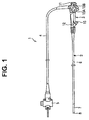
FIG. 1 illustrates an endoscope according to an embodiment of the present invention. -
FIG. 2 is a schematic view illustrating an inner structure of the endoscope. -
FIG. 3 is a cross-sectional view illustrating configurations of a corrugated tube portion and a bending portion of the endoscope. -
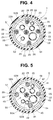
FIG. 4 is a cross-sectional view taken along Y4-Y4 line inFIG. 3 . -
FIG. 5 is a cross-sectional view taken along Y5-Y5 line inFIG. 3 . - Hereinafter, description will be made on the present invention with reference to the embodiment shown in the drawings.
- In the drawings used in the description below, there is a case where a different scale size is used for each of the constituent elements in order to allow each of the constituent elements to be illustrated in a recognizable size in the drawings. Therefore, in the present invention, the number, shapes, ratio of the sizes of the constituent elements, and a relative positional relationship among the constituent elements shown in these drawings are not limited to the embodiment shown in the drawings.
- With reference to
FIGS. 1 to 5 , an embodiment of the present invention will be described. - As shown in
FIG. 1 , an endoscope 1 is a bending apparatus and includes an elongated insertion portion 2 to be inserted into a body cavity which is a region to be examined, for example, and anoperation portion 3 coupled to the proximal end side of the insertion portion 2. Auniversal cord 4 is connected to the proximal end side of theoperation portion 3. A scope connector 5 is provided at the proximal end portion of theuniversal cord 4. - The insertion portion 2 includes an elongated and flexible
corrugated tube portion 6 as a tube, abending portion 7, which is a bending tube configured to be bendable and which is coupled to the distal end side of thecorrugated tube 6, and a distal end rigid portion 8 provided on the distal end side of thebending portion 7. Thecorrugated tube portion 6 has flexibility and is bent by an external force being applied thereto. The distal end rigid portion 8 is provided with an image pickup device (not shown) that picks up an image of an object, an air/water feeding nozzle (not shown), and the like. Note that the tube is not limited to the elongated and flexible corrugated tube portion, and may be a rigid and elongated tube portion. - The
operation portion 3 includes an operation portion casing 11, and aholding portion casing 12. The operation portion casing 11 is provided with an up/downbending operation knob 13 A that performs bending operation of thebending portion 7 in up and down directions and a right/leftbending operation knob 13B that performs bending operation of thebending portion 7 in right and left directions. - The
holding portion casing 12 is provided on the insertion portion 2 side with respect to the operation portion casing 11 and includes aforceps port 15. - Hereinafter, description will be made on an up/down bending operation mechanism for bending the
bending portion 7 in the up and down directions. - As shown in
FIG. 2 , theoperation portion 3 includes inside thereof apulley 21 as a rotation member, for example. Thepulley 21 is coupled to the up/downbending operation knob 13A. Thepulley 21 rotates in the direction of the arrow A or in the direction of the arrow B inFIG. 2 in accordance with the bending operation by the up/downbending operation knob 13A. Thepulley 21 is connected with one end of each of a pair ofbending operations wires bending operation knob 13A to thebending portion 7. - The
bending portion 7 includes abending piece group 31. Thebending piece group 31 is formed by rotatably coupling a plurality ofbending pieces 35 in the longitudinal direction. Each of thebending operation wires corrugated tube portion 6 and inside thebending portion 7 along the longitudinal axis of the insertion portion 2. - The other end of each of the
bending operation wires end bending piece 35A arranged on the distal most side of thebending piece group 31. That is, each of thebending operation wires operation portion 3 and the inside of thecorrugated tube portion 6, to be extended to the inside of thebending portion 7. - When the
pulley 21 is rotated in the direction of the arrow A inFIG. 2 by operating the up/down bendingoperation knob 13 A, the onebending operation wire 22A moves to the distal end side, and the otherbending operation wire 22B moves to the proximal end side. This causes the bendingportion 7 to bend in the direction of the arrow C (up direction) inFIG. 2 . Conversely, when thepulley 21 is rotated in the direction of the arrow B inFIG. 2 by operating the up/down bendingoperation knob 13A, the bendingoperation wire 22B moves to the distal end side and thebending operation wire 22A moves to the proximal end side. This causes the bendingportion 7 to bend in the direction opposite to the arrow C (down direction) inFIG. 2 . - Thus, the up/down bending operation mechanism that causes the bending
portion 7 to bend in the up and down directions is configured. - Note that the right/left bending operation mechanism that causes the bending
portion 7 to bend in the right and left directions has the same configuration as that of the up/down bending operation mechanism. Therefore, the description of the right/left bending operation mechanism will be omitted. - As shown in
FIG. 3 , thecorrugated tube portion 6 includes, in a layered manner, aspiral tube 41 made of metal, a corrugated tubeportion mesh tube 42 provided on the outer circumferential side of thespiral tube 41, and a corrugated tubeouter cover 43 which is made of resin and which covers the outer circumferential surface of the corrugated tubeportion mesh tube 42. Thespiral tube 41 is formed by spirally winding a metal band-like member at predetermined intervals. - The bending
portion 7 includes, in a layered manner, the above-describedbending piece group 31, a bendingportion mesh tube 32 provided on the outer circumferential side of thebending piece group 31, and a bending portionouter cover 33 which is made of rubber and which covers the outer circumferential surface of the bendingportion mesh tube 32. Thecorrugated tube portion 6 and the bendingportion 7 are configured by coupling a connectingpipe sleeve 37 of thecorrugated tube portion 6 with a proximalend bending piece 35B arranged on the proximal-most side of thebending piece group 31. - The connecting
pipe sleeve 37 includes a small-diameter portion 37A which has a substantially same diameter as that of thespiral tube 41, and a large-diameter portion 37B which is provided on the proximal end side of the small-diameter portion 37A and which has a diameter larger than that of the small-diameter portion 37A, for example. The proximalend bending piece 35B is disposed so as to be externally fitted to the small-diameter portion 37A of the connectingpipe sleeve 37. The large-diameter portion 37B of the connectingpipe sleeve 37 is disposed so as to be externally fitted to thespiral tube 41 and the corrugatedtube mesh tube 42. Thus, thecorrugated tube portion 6 and the bendingportion 7 are coupled with each other. In addition, in the part around a the distal end portion of the corrugated tubeouter cover 43 and the proximal end portion of the bending portionouter cover 33, athread 38 is wound around the corrugated tubeouter cover 43 and the bending portionouter cover 33, and thereafter an adhesive 39 is applied to the part. - As shown in
FIG. 4 and FIG. 5 , inside thecorrugated tube portion 6 and bendingportion 7, various kinds of long and flexibleinternal components 50 such as animage pickup cable 51, a light guide 52, an air/water feeding tube 53, aforceps tube 54, an auxiliarywater feeding tube 55, and the like are inserted. - The distal end portion of the
image pickup cable 51 is connected to an image pickup device (not shown) in the distal end rigid portion 8. The proximal end portion of theimage pickup cable 51 passes through theoperation portion 3 and theuniversal cord 4, to be connected to an image observation apparatus (not shown) through a scope connector 5. - The proximal end portion of the light guide 52 passes through the
operation portion 3 and theuniversal cord 4, to be connected to an illumination power source apparatus (not shown) through the scope connector 5. The light guide 52 guides the light for illuminating the object to an illumination window (not shown) of the distal end rigid portion 8. - The distal end portion of the air/
water feeding tube 53 is coupled with the air/water feeding channel (not shown) of the distal end rigid portion 8. The air/water feeding tube 53 is branched off to anair feeding tube 53A and awater feeding tube 53B inside thecorrugated tube portion 6. - The proximal end portion of the
air feeding tube 53A passes through theoperation portion 3 and theuniversal cord 4, to be connected to an air feeding apparatus (not shown) through the scope connector 5. The proximal end portion of thewater feeding tube 53B passes through theoperation portion 3 and theuniversal cord 4 to be connected to a water feeding apparatus (not shown) through the scope connector 5. - The distal end portion of the
forceps tube 54 is coupled with a forceps channel (not shown) of the distal end rigid portion 8. In addition, theforceps tube 54 is bifurcated inside theoperation portion 3, and one of the bifurcated portions is connected to theforceps port 15. The other of the bifurcated portions passes through theuniversal cord 4 to be connected to a suction apparatus (not shown) through the scope connector 5. - The distal end portion of the auxiliary
water feeding tube 55 is coupled with an auxiliary water feeding channel (not shown) of the distal end rigid portion 8. The proximal end portion of the auxiliarywater feeding tube 55 passes through theoperation portion 3 and theuniversal cord 4, to be connected to another water feeding apparatus (not shown) different from the water feeding apparatus that feeds water to the air/water feeding tube 53, through the scope connector 5. - As shown in
FIG. 3 andFIG. 5 , fourcoil pipes 45 are arranged inside thecorrugated tube portion 6, as four sheaths corresponding respectively to bending directions. Each of thecoil pipes 45 is formed by spirally winding an element wire and is a closed coil in which adjacent turns of the element wire contact with one another in a natural state. The sheaths are made of resin, for example. - The distal end portions of the four
coil pipes 45 are attached to previously determined positions of the connectingpipe sleeve 37 by soldering, for example, and arranged in thecorrugated tube portion 6. Inside each of thecoil pipes 45, one correspondingbending operation wire 22, which is among the bendingoperation wires operation wires operation wires 22 except in a predetermined case), is inserted so as to be able to move forward or backward along the longitudinal direction. That is, each of thecoil pipes 45 is a guide member configured by spirally winding the element wire around each of the operation wires, and one correspondingbending operation wire 22 among the bendingoperation wires 22 is inserted in each of thecoil pipes 45. - As shown in
FIG. 3 andFIG. 4 , the bendingoperation wires 22 are extended respectively from the distal end portions of thecoil pipes 45 further to the distal end side than the connectingpipe sleeve 37. The fourwire receivers 23 respectively corresponding to the bending directions are provided on the inner circumferential surface of each of the bendingpieces 35 constituting thebending piece group 31. - The
wire receivers 23 are arranged respectively at 90-degree intervals in the circumferential direction of the insertion portion 2. Each of thewire receivers 23 is a support portion having a through hole through which onebending operation wire 22 is inserted. One correspondingbending operation wire 22 among the fourbending operation wires 22 is arranged in each of thewire receivers 23. - The distal end portion of each of the
bending operation wires 22 is fixed to a wire stopper (not shown) provided at the distalend bending piece 35A. The bendingportion 7 is bent as described above by pulling or relaxing each of thebending operation wires 22 in the longitudinal direction of the insertion portion 2. - As shown in
FIG. 3 , on a part of the outer circumferential surface of each of thebending operation wires 22, acoating portion 25 of a predetermined thickness formed by coating processing is provided. Thecoating portion 25 is made of a material such as graphite-containing fluorine resin coating, PTFE (polytetrafluoroethylene)-nickel plating, PTFE-epoxy resin coating including epoxy resin and phenol resin as binder components. - The
coating portion 25 is provided on a range, which is located inside the bendingportion 7, of each of thebending operation wires 22. In other words, thecoating portion 25 is not provided on a range, which is inserted in each of thecoil pipes 45 provided inside thecorrugated tube portion 6, of each of thebending operation wires 22. - That is, the
coating portion 25 of each of thebending operation wires 22 is provided at the part contacting each of thewire receivers 23. - In the present embodiment, a powder lubricant (powder of the above-described solid lubricant) 26 is applied to the range of each of the
bending operation wires 22 where thecoating portion 25 is provided and to the range where thecoating portion 25 is not provided (bare part). - Description will be made on the working of the endoscope 1 according to the present embodiment.
- When the insertion portion 2 of the endoscope 1 is inserted into a body cavity and the bending
portion 7 is bent, the up/down bendingoperation knob 13 A is operated, for example. As a result, thepulley 21 rotates, to cause the downdirection bending wire 22B which is one of the pair of bendingoperation wires 22 to move to the distal end side, and cause the updirection bending wire 22A which is the other of the pair of bendingoperation wires 22 to move to the proximal end side. That is, the bendingportion 7 is bent in accordance with the pulling of the updirection bending wire 22A. - The range of each of the
bending operation wires 22 where thepowder lubricant 26 is applied on thecoating portion 25 slidingly moves in the bendingportion 7. On the other hand, the range of each of thebending operation wires 22 where thecoating portion 25 is not provided and only thepowder lubricant 26 is applied slidingly moves in each of thecoil pipes 45. - The
powder lubricant 26 applied to each of thebending operation wires 22 is fallen off by the each of the bending operation wires being slid as described above, but thepowder lubricant 26 fallen off in each of thecoil pipes 45, which is a part of thepowder lubricant 26 applied to each of thebending operation wires 22, adheres to the inner circumferential surface of each of thecoil pipes 45 and remains thereon. - As a result, when each of the
bending operation wires 22 slides in the longitudinal direction, the presence of thepowder lubricant 26 between the outer circumferential surface of each of thebending operation wires 22 and the inner circumferential surface of each of thecoil pipes 45 reduces the frictional force to be generated. Therefore, the amount of force of the bending operation at theoperation portion 3 is reduced. - When the bending
portion 7 is bent, each of thebending operation wires 22 contacts thewire receiver 23 to receive a large load. However, thecoating portion 25 is provided on the part of each of thebending operation wires 22, the part being arranged in the bendingportion 7, and thepowder lubricant 26 is applied on the surface of thecoating portion 25. Therefore, when each of thebending operation wires 22 contacts thewire receiver 23 and receives a load therefrom, the frictional force to be generated is reduced by the appliedpowder lubricant 26 in the initial state. In addition, since thecoating portion 25 of the predetermined thickness is provided, each of thewires 22 is not likely to receive a large load. In addition, the thickness of thecoating portion 25 is set to the predetermined thickness, which prevents thecoating portion 25 from being separated. - Therefore, cutting of the
bending operation wires 22 due to the load applied from thewire receivers 23 is effectively prevented. - Note that it is necessary to apply the
optimal powder lubricant 26 to thebending operation wires 22. Therefore, a plurality of kinds of power lubricants such as PTFE-based lubricant, silicone rubber-based lubricant, graphite-based lubricant, and graphite fluoride-based lubricant are prepared, to select thepowder lubricant 26 to be applied to thebending operation wires 22 by performing a test. - The test for selecting the lubricant is performed such that each of the above-described powder lubricants is applied to the non-coated
bending operation wire 22, thewire 22 to which the lubricant is applied is inserted in thecoil pipe 45, the bendingoperation wire 22 is repeatedly moved slidingly, the wire pulling force is measured when the wire is moved slidingly, and differences in the wire pulling forces for each of the lubricants are compared with one another. - As a result of the test, compared with the wire pulling force when the graphite fluoride-based lubricant is applied, the wire pulling force is increased by 50% when the PTFE-based lubricant is applied, increased by 50 to 100% when the silicone rubber-based lubricant is applied, and increased by more than 100% when the graphite-based lubricant is applied. Therefore, the graphite fluoride-based lubricant, which shows the lowest sliding resistance, is applied to the
bending operation wires 22 according to the present embodiment. - Thus, the lubricating property of the
bending operation wires 22 in the bendingportion 7 is ensured by thecoating portion 25, and the lubricating property of thebending operation wires 22 in thecoil pipes 45 is ensured by thepowder lubricant 26, which enables the amount of the bending operation force to be reduced and prevents the cutting of thebending operation wires 22 caused by the load, by effectively using the two lubricants in combination. - Note that each of the sheaths is a closed coil in the above description. However, instead of the closed coil, each of the sheaths may be formed by a plurality of ring-shaped members aligned so that each member contacts with the adjacent member, pipe-shaped members aligned so that each member contacts with the adjacent member, or one pipe-shaped member.
- In addition, in order to prevent the occurrence of such failure that the bare part of each of the
bending operation wires 22 to which the coating is not applied is arranged in the bendingportion 7 and cutting of each of the wires is caused, thecoating portion 25 is configured such that the range to which the coating processing is applied is set under the condition that the bare part does not get out of the sheath even in the case where the downdirection bending wire 22B is drawn into the bendingportion 7 when the updirection bending wire 22A is pulled to bring the bendingportion 7 into the maximum bent state in the up direction, for example. - Furthermore, as described above, when the
coating portion 25 applied to each of thebending operation wires 22 slides in each of thecoil pipes 45, the coating portion including the binder is likely to be peeled off, which may interfere with the forward or backward movement of each of thebending operation wires 22. Therefore, it is desirable to set the range to which the coating processing is applied to a minimum range that meets the above-described condition. - As result, occurrence of the failure that the bare part of the
bending operation wire 22 to which the coating is not applied is arranged in the bendingportion 7 and the wire is cut and occurrence of the failure caused by thecoating portion 25 sliding in each of thecoil pipes 45 are prevented. - Note that, in the present embodiment, an example in which the wires are bending
operation wires 22 is shown. However, the wires may be raising wires inserted into the insertion portion of the endoscope and pulled for raising a raising stand that is provided at the insertion portion and configured to raise a treatment instrument inserted into the insertion portion. - Note that, in the present embodiment, an example in which the wires are bending
operation wires 22 is shown. However, the wires may be transmission wires that transmit a driving force for rotating an insertion assisting portion around the longitudinal axis of the insertion portion, the insertion assisting portion being provided on the outer surface of the insertion portion and configured to move the insertion portion forward or backward with respect to the subject to be examined. - Note that, in the present embodiment, an example in which the wires are bending
operation wires 22 is shown. However, the wires may be lens operation wires inserted in the insertion portion and pulled for moving a photographing lens that is provided in the insertion portion and configured to be movable in the optical axis direction. - The bending apparatus is not limited to an endoscope, but may be other kinds of devices such as an insertion assisting instrument, a treatment instrument used with the endoscope, and the like, other than the endoscope.
- Note that the present invention is not limited only to the above-mentioned embodiment, but may be modified and embodied in various forms without departing from the gist of the present invention.
- The present invention is capable of providing a bending apparatus that reduces an amount of operation force at the time of bending operation and preventing bending operation wires from being cut in a bending portion.
- The present application claims the benefit of Japanese Patent Application No.
2014-172988
Claims (12)
- A wire apparatus comprising:a sheath arranged inside an endoscope; anda wire inserted in the sheath and moved in an axial direction or rotated in the sheath,wherein the wire is configured such that processing for coating including a binder component is performed only on a range of the wire, the range being exposed from the sheath, and a powder lubricant which does not include the binder component is applied to at least a range of the wire, the range being inserted in the sheath.
- The wire apparatus according to claim 1, wherein the sheath is made of resin.
- The wire apparatus according to claim 1, wherein the powder lubricant is applied to the range of the wire where the coating processing is performed and the range of the wire where the coating processing is not performed.
- The wire apparatus according to claim 1, wherein the powder lubricant is graphite fluoride.
- An endoscope including the wire apparatus according to claim 1.
- The endoscope according to claim 5, further comprising:an insertion portion to be inserted into a subject to be examined;a bendable bending tube provided at the insertion portion,wherein the wire is a bending operation wire inserted in the insertion portion and pulled for bending the bending tube.
- The endoscope according to claim 6, wherein
the bending operation wire is configured by a pair of wires,
the pair of wires is coupled with the bending tube so as to cause the bending tube to bend in directions different from each other, and
the processing for coating is performed such that a range where the coating processing is performed is set so as to prevent the range where the coating processing is not performed from getting out of the sheath in a state where one of the pair of the wires is pulled to bring the bending tube into a maximum bent state, to thereby cause the pair of the bending wires to be drawn into the bending tube. - The endoscope according to claim 6, wherein the bending tube includes a bending piece group configured by rotatably coupling a plurality of bending pieces.
- The endoscope according to claim 6, wherein the sheath is formed by spirally winding an element wire, and the bending operation wire is inserted so as to be able to move forward or backward in the sheath.
- The endoscope according to claim 5, comprising:an insertion portion to be inserted into a subject to be examined; anda raising stand provided to the insertion portion and configured to raise a treatment instrument inserted in the insertion portion,wherein the wire is a raising wire inserted in the insertion portion and pulled for performing raising operation of the raising stand.
- The endoscope according to claim 5, comprising:an insertion portion to be inserted into a subject to be examined; anda photographing lens provided in the insertion portion and movable in an optical axis direction,wherein the wire is a lens operation wire inserted in the insertion portion and pulled for moving the photographing lens.
- The endoscope according to claim 5, comprising:an insertion portion to be inserted into a subject to be examined; andan insertion assisting portion provided on an outer surface of the insertion portion and configured to move the insertion portion forward or backward with respect to the subject to be examined,wherein the wire is a transmission wire that transmits a driving force for rotating the insertion assisting portion around a longitudinal axis direction of the insertion portion.
Applications Claiming Priority (2)
| Application Number | Priority Date | Filing Date | Title |
|---|---|---|---|
| JP2014172988 | 2014-08-27 | ||
| PCT/JP2015/070358 WO2016031419A1 (en) | 2014-08-27 | 2015-07-16 | Wire device and endoscope |
Publications (3)
| Publication Number | Publication Date |
|---|---|
| EP3078320A1 true EP3078320A1 (en) | 2016-10-12 |
| EP3078320A4 EP3078320A4 (en) | 2017-08-30 |
| EP3078320B1 EP3078320B1 (en) | 2018-09-12 |
Family
ID=55399320
Family Applications (1)
| Application Number | Title | Priority Date | Filing Date |
|---|---|---|---|
| EP15835602.2A Active EP3078320B1 (en) | 2014-08-27 | 2015-07-16 | Wire device and endoscope |
Country Status (4)
| Country | Link |
|---|---|
| US (1) | US20160302645A1 (en) |
| EP (1) | EP3078320B1 (en) |
| JP (1) | JP5914781B1 (en) |
| WO (1) | WO2016031419A1 (en) |
Families Citing this family (1)
| Publication number | Priority date | Publication date | Assignee | Title |
|---|---|---|---|---|
| US12048419B2 (en) | 2022-07-07 | 2024-07-30 | Hoya Corporation | Peroxide-resistant flexible endoscope, and methods of reprocessing or sterilizing such endoscope |
Family Cites Families (10)
| Publication number | Priority date | Publication date | Assignee | Title |
|---|---|---|---|---|
| JPH0814656B2 (en) * | 1985-12-06 | 1996-02-14 | オリンパス光学工業株式会社 | Endoscope |
| US5752912A (en) * | 1995-06-26 | 1998-05-19 | Asahi Kogaku Kogyo Kabushiki Kaisha | Manipulator for flexible portion of an endoscope |
| JP2000166858A (en) * | 1998-12-10 | 2000-06-20 | Olympus Optical Co Ltd | Endoscope |
| US8500628B2 (en) * | 2006-02-28 | 2013-08-06 | Olympus Endo Technology America, Inc. | Rotate-to-advance catheterization system |
| BRPI0819253B1 (en) * | 2007-11-02 | 2022-09-20 | Vallourec Oil And Gas France | COMPOSITION FOR FORMING A LUBRICANT COATING ON A THREADED JOINT FOR PIPES |
| WO2012014532A1 (en) * | 2010-07-28 | 2012-02-02 | オリンパスメディカルシステムズ株式会社 | Endoscope, and method for inserting and bending the endoscope |
| WO2012173082A1 (en) * | 2011-06-16 | 2012-12-20 | オリンパスメディカルシステムズ株式会社 | Endoscope |
| WO2013031280A1 (en) * | 2011-09-01 | 2013-03-07 | オリンパスメディカルシステムズ株式会社 | Endsoscope |
| JP5527904B2 (en) * | 2011-11-28 | 2014-06-25 | 富士フイルム株式会社 | Endoscope |
| JP5901469B2 (en) * | 2012-08-10 | 2016-04-13 | オリンパス株式会社 | Endoscope |
-
2015
- 2015-07-16 EP EP15835602.2A patent/EP3078320B1/en active Active
- 2015-07-16 WO PCT/JP2015/070358 patent/WO2016031419A1/en not_active Ceased
- 2015-07-16 JP JP2015558280A patent/JP5914781B1/en not_active Expired - Fee Related
-
2016
- 2016-06-29 US US15/196,250 patent/US20160302645A1/en not_active Abandoned
Also Published As
| Publication number | Publication date |
|---|---|
| WO2016031419A1 (en) | 2016-03-03 |
| JPWO2016031419A1 (en) | 2017-04-27 |
| US20160302645A1 (en) | 2016-10-20 |
| JP5914781B1 (en) | 2016-05-11 |
| EP3078320A4 (en) | 2017-08-30 |
| EP3078320B1 (en) | 2018-09-12 |
Similar Documents
| Publication | Publication Date | Title |
|---|---|---|
| US8663097B2 (en) | Insertion device | |
| EP2457491B1 (en) | Endoscope | |
| US9872607B2 (en) | Endoscope | |
| JP2008220443A (en) | Bending device of endoscope | |
| EP2870909A1 (en) | Endoscope | |
| CN108135451B (en) | Insert device | |
| US20190082934A1 (en) | Flexible tube for endoscope | |
| EP3087898A1 (en) | Endoscope | |
| CN105722447A (en) | Insertion instrument, rotation unit, and insertion device | |
| US10653303B2 (en) | Endoscope and hardness adjustment device | |
| EP2898816A1 (en) | Insertion aid, insertion body, and insertion device | |
| EP2984981A1 (en) | Coil structure used for endoscope, and endoscope and treatment instrument each comprising said coil structure | |
| US9649017B2 (en) | Endoscope | |
| US20150313447A1 (en) | Insertion instrument and endoscope | |
| JP5901469B2 (en) | Endoscope | |
| JPWO2019031018A1 (en) | Endoscope | |
| US9770158B2 (en) | Holding mechanism for endoscope guide member, and endoscope | |
| EP3078320B1 (en) | Wire device and endoscope | |
| US20110288375A1 (en) | Endoscope | |
| US20170245738A1 (en) | Endoscope | |
| CN112004452B (en) | Spiral tube and endoscope | |
| US20200146536A1 (en) | Endoscope | |
| EP2832282A1 (en) | Insertion device, rotating tubular member and drive unit | |
| US20170000312A1 (en) | Bending device and endoscope | |
| US20170202440A1 (en) | Insertion apparatus |
Legal Events
| Date | Code | Title | Description |
|---|---|---|---|
| PUAI | Public reference made under article 153(3) epc to a published international application that has entered the european phase |
Free format text: ORIGINAL CODE: 0009012 |
|
| 17P | Request for examination filed |
Effective date: 20160623 |
|
| AK | Designated contracting states |
Kind code of ref document: A1 Designated state(s): AL AT BE BG CH CY CZ DE DK EE ES FI FR GB GR HR HU IE IS IT LI LT LU LV MC MK MT NL NO PL PT RO RS SE SI SK SM TR |
|
| AX | Request for extension of the european patent |
Extension state: BA ME |
|
| RIN1 | Information on inventor provided before grant (corrected) |
Inventor name: OKAZAKI, TSUGIO Inventor name: MIYAGI, MASAAKI Inventor name: SHIGA, NAOHITO |
|
| A4 | Supplementary search report drawn up and despatched |
Effective date: 20170727 |
|
| RIC1 | Information provided on ipc code assigned before grant |
Ipc: A61B 1/00 20060101AFI20170721BHEP Ipc: G02B 23/24 20060101ALI20170721BHEP Ipc: A61M 25/01 20060101ALI20170721BHEP |
|
| DAV | Request for validation of the european patent (deleted) | ||
| DAX | Request for extension of the european patent (deleted) | ||
| GRAP | Despatch of communication of intention to grant a patent |
Free format text: ORIGINAL CODE: EPIDOSNIGR1 |
|
| STAA | Information on the status of an ep patent application or granted ep patent |
Free format text: STATUS: GRANT OF PATENT IS INTENDED |
|
| INTG | Intention to grant announced |
Effective date: 20180301 |
|
| RIN1 | Information on inventor provided before grant (corrected) |
Inventor name: MIYAGI, MASAAKI Inventor name: SHIGA, NAOHITO Inventor name: OKAZAKI, TSUGIO |
|
| GRAJ | Information related to disapproval of communication of intention to grant by the applicant or resumption of examination proceedings by the epo deleted |
Free format text: ORIGINAL CODE: EPIDOSDIGR1 |
|
| STAA | Information on the status of an ep patent application or granted ep patent |
Free format text: STATUS: REQUEST FOR EXAMINATION WAS MADE |
|
| GRAR | Information related to intention to grant a patent recorded |
Free format text: ORIGINAL CODE: EPIDOSNIGR71 |
|
| GRAS | Grant fee paid |
Free format text: ORIGINAL CODE: EPIDOSNIGR3 |
|
| STAA | Information on the status of an ep patent application or granted ep patent |
Free format text: STATUS: GRANT OF PATENT IS INTENDED |
|
| INTC | Intention to grant announced (deleted) | ||
| RIN1 | Information on inventor provided before grant (corrected) |
Inventor name: SHIGA, NAOHITO Inventor name: MIYAGI, MASAAKI Inventor name: OKAZAKI, TSUGIO |
|
| INTG | Intention to grant announced |
Effective date: 20180620 |
|
| GRAA | (expected) grant |
Free format text: ORIGINAL CODE: 0009210 |
|
| STAA | Information on the status of an ep patent application or granted ep patent |
Free format text: STATUS: THE PATENT HAS BEEN GRANTED |
|
| AK | Designated contracting states |
Kind code of ref document: B1 Designated state(s): AL AT BE BG CH CY CZ DE DK EE ES FI FR GB GR HR HU IE IS IT LI LT LU LV MC MK MT NL NO PL PT RO RS SE SI SK SM TR |
|
| REG | Reference to a national code |
Ref country code: GB Ref legal event code: FG4D |
|
| REG | Reference to a national code |
Ref country code: CH Ref legal event code: EP |
|
| REG | Reference to a national code |
Ref country code: IE Ref legal event code: FG4D |
|
| REG | Reference to a national code |
Ref country code: DE Ref legal event code: R096 Ref document number: 602015016373 Country of ref document: DE |
|
| REG | Reference to a national code |
Ref country code: AT Ref legal event code: REF Ref document number: 1039608 Country of ref document: AT Kind code of ref document: T Effective date: 20181015 |
|
| REG | Reference to a national code |
Ref country code: NL Ref legal event code: MP Effective date: 20180912 |
|
| REG | Reference to a national code |
Ref country code: LT Ref legal event code: MG4D |
|
| PG25 | Lapsed in a contracting state [announced via postgrant information from national office to epo] |
Ref country code: FI Free format text: LAPSE BECAUSE OF FAILURE TO SUBMIT A TRANSLATION OF THE DESCRIPTION OR TO PAY THE FEE WITHIN THE PRESCRIBED TIME-LIMIT Effective date: 20180912 Ref country code: GR Free format text: LAPSE BECAUSE OF FAILURE TO SUBMIT A TRANSLATION OF THE DESCRIPTION OR TO PAY THE FEE WITHIN THE PRESCRIBED TIME-LIMIT Effective date: 20181213 Ref country code: NO Free format text: LAPSE BECAUSE OF FAILURE TO SUBMIT A TRANSLATION OF THE DESCRIPTION OR TO PAY THE FEE WITHIN THE PRESCRIBED TIME-LIMIT Effective date: 20181212 Ref country code: RS Free format text: LAPSE BECAUSE OF FAILURE TO SUBMIT A TRANSLATION OF THE DESCRIPTION OR TO PAY THE FEE WITHIN THE PRESCRIBED TIME-LIMIT Effective date: 20180912 Ref country code: LT Free format text: LAPSE BECAUSE OF FAILURE TO SUBMIT A TRANSLATION OF THE DESCRIPTION OR TO PAY THE FEE WITHIN THE PRESCRIBED TIME-LIMIT Effective date: 20180912 Ref country code: BG Free format text: LAPSE BECAUSE OF FAILURE TO SUBMIT A TRANSLATION OF THE DESCRIPTION OR TO PAY THE FEE WITHIN THE PRESCRIBED TIME-LIMIT Effective date: 20181212 Ref country code: SE Free format text: LAPSE BECAUSE OF FAILURE TO SUBMIT A TRANSLATION OF THE DESCRIPTION OR TO PAY THE FEE WITHIN THE PRESCRIBED TIME-LIMIT Effective date: 20180912 |
|
| PG25 | Lapsed in a contracting state [announced via postgrant information from national office to epo] |
Ref country code: AL Free format text: LAPSE BECAUSE OF FAILURE TO SUBMIT A TRANSLATION OF THE DESCRIPTION OR TO PAY THE FEE WITHIN THE PRESCRIBED TIME-LIMIT Effective date: 20180912 Ref country code: LV Free format text: LAPSE BECAUSE OF FAILURE TO SUBMIT A TRANSLATION OF THE DESCRIPTION OR TO PAY THE FEE WITHIN THE PRESCRIBED TIME-LIMIT Effective date: 20180912 Ref country code: HR Free format text: LAPSE BECAUSE OF FAILURE TO SUBMIT A TRANSLATION OF THE DESCRIPTION OR TO PAY THE FEE WITHIN THE PRESCRIBED TIME-LIMIT Effective date: 20180912 |
|
| REG | Reference to a national code |
Ref country code: AT Ref legal event code: MK05 Ref document number: 1039608 Country of ref document: AT Kind code of ref document: T Effective date: 20180912 |
|
| PG25 | Lapsed in a contracting state [announced via postgrant information from national office to epo] |
Ref country code: IS Free format text: LAPSE BECAUSE OF FAILURE TO SUBMIT A TRANSLATION OF THE DESCRIPTION OR TO PAY THE FEE WITHIN THE PRESCRIBED TIME-LIMIT Effective date: 20190112 Ref country code: ES Free format text: LAPSE BECAUSE OF FAILURE TO SUBMIT A TRANSLATION OF THE DESCRIPTION OR TO PAY THE FEE WITHIN THE PRESCRIBED TIME-LIMIT Effective date: 20180912 Ref country code: NL Free format text: LAPSE BECAUSE OF FAILURE TO SUBMIT A TRANSLATION OF THE DESCRIPTION OR TO PAY THE FEE WITHIN THE PRESCRIBED TIME-LIMIT Effective date: 20180912 Ref country code: PL Free format text: LAPSE BECAUSE OF FAILURE TO SUBMIT A TRANSLATION OF THE DESCRIPTION OR TO PAY THE FEE WITHIN THE PRESCRIBED TIME-LIMIT Effective date: 20180912 Ref country code: IT Free format text: LAPSE BECAUSE OF FAILURE TO SUBMIT A TRANSLATION OF THE DESCRIPTION OR TO PAY THE FEE WITHIN THE PRESCRIBED TIME-LIMIT Effective date: 20180912 Ref country code: RO Free format text: LAPSE BECAUSE OF FAILURE TO SUBMIT A TRANSLATION OF THE DESCRIPTION OR TO PAY THE FEE WITHIN THE PRESCRIBED TIME-LIMIT Effective date: 20180912 Ref country code: CZ Free format text: LAPSE BECAUSE OF FAILURE TO SUBMIT A TRANSLATION OF THE DESCRIPTION OR TO PAY THE FEE WITHIN THE PRESCRIBED TIME-LIMIT Effective date: 20180912 Ref country code: AT Free format text: LAPSE BECAUSE OF FAILURE TO SUBMIT A TRANSLATION OF THE DESCRIPTION OR TO PAY THE FEE WITHIN THE PRESCRIBED TIME-LIMIT Effective date: 20180912 Ref country code: EE Free format text: LAPSE BECAUSE OF FAILURE TO SUBMIT A TRANSLATION OF THE DESCRIPTION OR TO PAY THE FEE WITHIN THE PRESCRIBED TIME-LIMIT Effective date: 20180912 |
|
| PG25 | Lapsed in a contracting state [announced via postgrant information from national office to epo] |
Ref country code: SM Free format text: LAPSE BECAUSE OF FAILURE TO SUBMIT A TRANSLATION OF THE DESCRIPTION OR TO PAY THE FEE WITHIN THE PRESCRIBED TIME-LIMIT Effective date: 20180912 Ref country code: SK Free format text: LAPSE BECAUSE OF FAILURE TO SUBMIT A TRANSLATION OF THE DESCRIPTION OR TO PAY THE FEE WITHIN THE PRESCRIBED TIME-LIMIT Effective date: 20180912 Ref country code: PT Free format text: LAPSE BECAUSE OF FAILURE TO SUBMIT A TRANSLATION OF THE DESCRIPTION OR TO PAY THE FEE WITHIN THE PRESCRIBED TIME-LIMIT Effective date: 20190112 |
|
| REG | Reference to a national code |
Ref country code: DE Ref legal event code: R097 Ref document number: 602015016373 Country of ref document: DE |
|
| PLBE | No opposition filed within time limit |
Free format text: ORIGINAL CODE: 0009261 |
|
| STAA | Information on the status of an ep patent application or granted ep patent |
Free format text: STATUS: NO OPPOSITION FILED WITHIN TIME LIMIT |
|
| PG25 | Lapsed in a contracting state [announced via postgrant information from national office to epo] |
Ref country code: DK Free format text: LAPSE BECAUSE OF FAILURE TO SUBMIT A TRANSLATION OF THE DESCRIPTION OR TO PAY THE FEE WITHIN THE PRESCRIBED TIME-LIMIT Effective date: 20180912 |
|
| 26N | No opposition filed |
Effective date: 20190613 |
|
| PG25 | Lapsed in a contracting state [announced via postgrant information from national office to epo] |
Ref country code: SI Free format text: LAPSE BECAUSE OF FAILURE TO SUBMIT A TRANSLATION OF THE DESCRIPTION OR TO PAY THE FEE WITHIN THE PRESCRIBED TIME-LIMIT Effective date: 20180912 |
|
| PG25 | Lapsed in a contracting state [announced via postgrant information from national office to epo] |
Ref country code: MC Free format text: LAPSE BECAUSE OF FAILURE TO SUBMIT A TRANSLATION OF THE DESCRIPTION OR TO PAY THE FEE WITHIN THE PRESCRIBED TIME-LIMIT Effective date: 20180912 |
|
| REG | Reference to a national code |
Ref country code: CH Ref legal event code: PL |
|
| GBPC | Gb: european patent ceased through non-payment of renewal fee |
Effective date: 20190716 |
|
| PG25 | Lapsed in a contracting state [announced via postgrant information from national office to epo] |
Ref country code: TR Free format text: LAPSE BECAUSE OF FAILURE TO SUBMIT A TRANSLATION OF THE DESCRIPTION OR TO PAY THE FEE WITHIN THE PRESCRIBED TIME-LIMIT Effective date: 20180912 |
|
| REG | Reference to a national code |
Ref country code: BE Ref legal event code: MM Effective date: 20190731 |
|
| PG25 | Lapsed in a contracting state [announced via postgrant information from national office to epo] |
Ref country code: GB Free format text: LAPSE BECAUSE OF NON-PAYMENT OF DUE FEES Effective date: 20190716 |
|
| PG25 | Lapsed in a contracting state [announced via postgrant information from national office to epo] |
Ref country code: LI Free format text: LAPSE BECAUSE OF NON-PAYMENT OF DUE FEES Effective date: 20190731 Ref country code: CH Free format text: LAPSE BECAUSE OF NON-PAYMENT OF DUE FEES Effective date: 20190731 Ref country code: LU Free format text: LAPSE BECAUSE OF NON-PAYMENT OF DUE FEES Effective date: 20190716 Ref country code: BE Free format text: LAPSE BECAUSE OF NON-PAYMENT OF DUE FEES Effective date: 20190731 |
|
| PG25 | Lapsed in a contracting state [announced via postgrant information from national office to epo] |
Ref country code: FR Free format text: LAPSE BECAUSE OF NON-PAYMENT OF DUE FEES Effective date: 20190731 |
|
| PG25 | Lapsed in a contracting state [announced via postgrant information from national office to epo] |
Ref country code: IE Free format text: LAPSE BECAUSE OF NON-PAYMENT OF DUE FEES Effective date: 20190716 |
|
| PG25 | Lapsed in a contracting state [announced via postgrant information from national office to epo] |
Ref country code: CY Free format text: LAPSE BECAUSE OF FAILURE TO SUBMIT A TRANSLATION OF THE DESCRIPTION OR TO PAY THE FEE WITHIN THE PRESCRIBED TIME-LIMIT Effective date: 20180912 |
|
| PG25 | Lapsed in a contracting state [announced via postgrant information from national office to epo] |
Ref country code: HU Free format text: LAPSE BECAUSE OF FAILURE TO SUBMIT A TRANSLATION OF THE DESCRIPTION OR TO PAY THE FEE WITHIN THE PRESCRIBED TIME-LIMIT; INVALID AB INITIO Effective date: 20150716 Ref country code: MT Free format text: LAPSE BECAUSE OF FAILURE TO SUBMIT A TRANSLATION OF THE DESCRIPTION OR TO PAY THE FEE WITHIN THE PRESCRIBED TIME-LIMIT Effective date: 20180912 |
|
| PG25 | Lapsed in a contracting state [announced via postgrant information from national office to epo] |
Ref country code: MK Free format text: LAPSE BECAUSE OF FAILURE TO SUBMIT A TRANSLATION OF THE DESCRIPTION OR TO PAY THE FEE WITHIN THE PRESCRIBED TIME-LIMIT Effective date: 20180912 |
|
| P01 | Opt-out of the competence of the unified patent court (upc) registered |
Effective date: 20230528 |
|
| PGFP | Annual fee paid to national office [announced via postgrant information from national office to epo] |
Ref country code: DE Payment date: 20250722 Year of fee payment: 11 |