EP3078257A1 - Plunger and pre-compression chamber link - Google Patents
Plunger and pre-compression chamber link Download PDFInfo
- Publication number
- EP3078257A1 EP3078257A1 EP16164330.9A EP16164330A EP3078257A1 EP 3078257 A1 EP3078257 A1 EP 3078257A1 EP 16164330 A EP16164330 A EP 16164330A EP 3078257 A1 EP3078257 A1 EP 3078257A1
- Authority
- EP
- European Patent Office
- Prior art keywords
- gear
- slice
- plunger
- intermediary element
- pushing
- Prior art date
- Legal status (The legal status is an assumption and is not a legal conclusion. Google has not performed a legal analysis and makes no representation as to the accuracy of the status listed.)
- Granted
Links
Images

Classifications
-
- A—HUMAN NECESSITIES
- A01—AGRICULTURE; FORESTRY; ANIMAL HUSBANDRY; HUNTING; TRAPPING; FISHING
- A01F—PROCESSING OF HARVESTED PRODUCE; HAY OR STRAW PRESSES; DEVICES FOR STORING AGRICULTURAL OR HORTICULTURAL PRODUCE
- A01F15/00—Baling presses for straw, hay or the like
- A01F15/08—Details
- A01F15/0841—Drives for balers
-
- A—HUMAN NECESSITIES
- A01—AGRICULTURE; FORESTRY; ANIMAL HUSBANDRY; HUNTING; TRAPPING; FISHING
- A01F—PROCESSING OF HARVESTED PRODUCE; HAY OR STRAW PRESSES; DEVICES FOR STORING AGRICULTURAL OR HORTICULTURAL PRODUCE
- A01F15/00—Baling presses for straw, hay or the like
- A01F15/08—Details
- A01F15/0825—Regulating or controlling density or shape of the bale
-
- A—HUMAN NECESSITIES
- A01—AGRICULTURE; FORESTRY; ANIMAL HUSBANDRY; HUNTING; TRAPPING; FISHING
- A01F—PROCESSING OF HARVESTED PRODUCE; HAY OR STRAW PRESSES; DEVICES FOR STORING AGRICULTURAL OR HORTICULTURAL PRODUCE
- A01F15/00—Baling presses for straw, hay or the like
- A01F15/08—Details
- A01F15/10—Feeding devices for the crop material e.g. precompression devices
- A01F15/101—Feeding at right angles to the compression stroke
-
- A—HUMAN NECESSITIES
- A01—AGRICULTURE; FORESTRY; ANIMAL HUSBANDRY; HUNTING; TRAPPING; FISHING
- A01F—PROCESSING OF HARVESTED PRODUCE; HAY OR STRAW PRESSES; DEVICES FOR STORING AGRICULTURAL OR HORTICULTURAL PRODUCE
- A01F15/00—Baling presses for straw, hay or the like
- A01F15/08—Details
- A01F15/10—Feeding devices for the crop material e.g. precompression devices
- A01F15/101—Feeding at right angles to the compression stroke
- A01F2015/102—Feeding at right angles to the compression stroke the pressing chamber is fed from the bottom side
Definitions
- the present invention relates to an agricultural baler.
- the present invention relates to a square agricultural baler, which is provided for gathering crop material, forming slices of crop material from the gathered crop material, and pressing square bales from the slices.
- Agricultural balers typically comprise two main parts used in the formation of the bales, being a pre-compression chamber and a baling chamber. Crop material is gathered and pushed into the pre-compression chamber, where a slice of crop material is formed. Pre-compression chamber is linked to the baling chamber in such a manner that the slice of crop material can periodically be transferred into the baling chamber. In the baling chamber, a plunger reciprocally moves, thereby pressing a square bale from subsequently feeded slices.
- the plunger movement is powered via a main shaft driven by a motor.
- the motor can be a part of the baler, or can be a part of e.g. the tractor connected to the baler via a power take-off (PTO).
- PTO power take-off
- this reciprocal movement of the plunger is often considered the most dominant movement in the baler, dominant meaning that other movements are made relative to this movement of the plunger. The reason is that the plunger movement requires the highest force (highest relative to other forces needed for operating the baler). Off all movements in the baler, the movement of the plunger shows the highest inertia.
- the pre-compression chamber is adapted for receiving gathered crop material.
- the pre-compression chamber shows an inlet.
- the pre-compression chamber furthermore shows an outlet towards the baling chamber. Between the inlet and the outlet, a channel is defined in which crop material can gather into a slice of crop material.
- the pre-compression chamber comprises a slice pushing mechanism provided for pushing a slice of crop material formed in the pre-compression chamber through the outlet of the pre-compression chamber into the baling chamber.
- the sliced crop material is typically pushed in a first segment of the baling chamber. First segment is typically located directly behind the plunger (the plunger being in the withdrawn position). Thereby the slice of crop material is pushed in the baling chamber, after which the plunger can propel the crop material into the baling chamber, thereby pushing the most recently entered slice into the baling chamber, making it a part of the square bale.
- the pre-compression chamber comprises, for the purpose of pushing the slice into the baling chamber, a slice pushing mechanism.
- a slice pushing mechanism for the purpose of pushing the slice into the baling chamber.
- Different types of slice pushing mechanisms are known, among which fingers grasping behind the slice and pushing the slice through the outlet, or a set of conveyer belts in between which the slice is formed, and which conveyer belts are driven to push the slice through the outlet.
- the slice pushing mechanism is driven via a driving mechanism that is operationally linked to the plunger driving mechanism.
- a synchronized movement between the slice pushing mechanism and the plunger is needed to ensure a proper operation of the baler. Namely, only when the plunger is withdrawn, a slice can be pushed in the baling chamber.
- different synchronization types are possible among which a one/one synchronization, meaning that every withdrawal of the plunger a new slice is entered into the baling chamber, or a one/two synchronization, meaning that every other withdrawal of the plunger a new slice is entered, thus the plunger moves forth and back two times for each slice.
- Other synchronization timing such as one/three, one/four,... are also possible.
- Synchronization is in practice realized by mechanically linking the plunger driving mechanism and the slice pushing driving mechanism. Such mechanical link ensures proper synchronization, as the slice pushing mechanism is mechanically driven by the plunger movement, it cannot move out of synchronization.
- Top fill is a measure for the uniformity of the slice after it has entered the first segment of the baling chamber. It will be recognized that a non uniform fill, for example where the lower part of the first segment is more dense than an upper part, results in an inferior bale. Such top fill has an effect that a bale is high dense at the lower end, and not dense at the top, resulting in an unstable bale that is likely to show a substantial deviation from the ideal square form. Such bale will bend like a banana resulting in a weirdly shaped bale. A negative top fill also results in a substantial wear of the plunger and baling chamber, as forces are not equally transmitted.
- the plunger will feel a substantially high resistance at the lower part of the plunger compared to the upper part resistance of the plunger. This will create a torque force exerted to the plunger which has to be borne by the plunger driving mechanism.
- the ideal top fill is obtained by controlling the slice forming process in the pre-compression chamber. By obtaining a slice in which the crop material is evenly spread over the slice, after which the slice is pushed into the baling chamber, an acceptable top fill can be obtained.
- a drawback of the existing top fill controlling mechanisms is that a deviation of the top fill can still occur depending on the baling speed and the type of crop material (hay, straw, silage, ).
- the invention provides an agricultural baler comprising a baling chamber with a plunger that is provided to reciprocally move in the baling chamber, the baler further comprising a pre-compression chamber with a slice pushing mechanism provided for periodically pushing a slice of crop material into the baling chamber, the plunger and the pushing mechanism being mechanically linked via their respective driving systems to ensure synchronization, wherein coupling means are mounted in the mechanical link, the coupling means being provided to adjust a synchronization timing.
- a mechanical connection is often provided between the plunger driving mechanism and the slice pushing driving mechanism.
- This mechanical connection ensures a correct synchronized movement between the plunger and the crop pushing mechanism. This prevents the crop pushing mechanism from pushing a slice of crop material into the baling chamber if the baling chamber is not ready to receive the slice crop material (for example when the plunger is in its extended position thereby closing off the first segment of the baling chamber).
- the synchronization timing can be adjusted. Thereby, the synchronization can be fine-tuned meaning that the moment of arrival of the slice of crop material into the first segment of the baling chamber can be somewhat shifted.
- the mechanical connection is maintained ensuring a correct synchronization (in the broad sense of synchronization) while enabling the controller to adjust the synchronization (thereby obtaining a fine-tuned synchronization).
- the top-fill can be influenced and thereby optimized. As a result, via the coupling element the top-fill is controllable.
- the coupling means are formed as an intermediary element linking two rotating shafts, a first one connected to a plunger driving system and a second one connected to a pushing mechanism driving system.
- Mechanically linking the plunger with the pre-compression chamber's pushing mechanism can be achieved via linking their respective driving systems.
- Such link provides a reliable connection and is easy to implement on an agricultural baler.
- a position of the intermediary element determines the synchronization timing.
- the top-fill is controllable.
- the position can be steered manually or via an actuator or via other known mechanism.
- the desired position can be determined manually or automatically so that the synchronization timing can be amended and thereby the top-fill can be controlled.
- the intermediary element is movable to adjust the relative position of the two rotating shafts with respect to each other thereby adjusting the synchronization timing
- the intermediary element is movable between a first position and a second position, wherein the relative angular position of the two rotating shafts with respect to each other when the intermediary element is in the first position, is different from the relative angular position of the two rotating shafts with respect to each other when the intermediary element is in the second position.
- Multiple mechanisms are known wherein the intermediary elements position is determining for the angular position of the shafts linked via the intermediary position.
- the intermediary element is formed as a planetary gearbox having an outer gear, at least two planet gears and a central gear, whereby the plunger driving system is coupled to one of the outer gear, two planet gears and central gear, and whereby the pushing mechanism driving system is coupled to another of the outer gear, two planet gears and central gear, and whereby an actuator is coupled to the yet another of the outer gear, two planet gears and central gear to displace the latter thereby adjusting the relative position of the plunger driving system and the pushing mechanism driving system.
- a planetary gearbox is known for linking three rotational movements (respectively via the central gear, the planet gears and the outer gear).
- the planetary gearbox can be used in the present case to link the plunger driving mechanism, the pushing mechanism driving system, and an actuator.
- the actuator stands still, there is a constant predictable link between rotational speed of the plunger driving mechanism and the pushing mechanism driving system, meaning that the relative movement of one with respect to the other is fixed.
- the synchronization timing is also fixed.
- the actuator connected to the planetary gearbox, the relative position of the plunger driving mechanism and the pushing mechanism driving system changes. Thereby, synchronization optimization is made possible.
- a skilled person can, based on the principles explained in this disclosure, test and/or determine several planetary gearbox constructions, and can test and/or determine the influence of the actuator to the synchronization timing.
- the intermediary element has a first end being provided with a straight gear and a second end being provided with a helical gear.
- a two part gearbox is formed whereby one end is connected via a straight gear coupling and another end is connected via a helical gear coupling.
- Such two part gearbox is known in the art for amending the relative position of two shafts while connecting the shafts in a rotational movement.
- the two part gearbox is in a fixed position, the two shafts are directly connected to one another. Thereby, rotational movement and forces can be transmitted from one shaft to another.
- the gearbox By displacing the gearbox along its longitudinal axis, the relative position of the two shafts is amended.
- the intermediary element is mounted between an input gear and an output gear, whereby the input gear comprises a helical inner shape matching with the helical gear and whereby the output gear comprises a straight inner shape matching with the straight gear, the input gear being mounted at a fixed distance with respect to the output gear, so that moving the intermediary element or input gear in the direction of its axis results in a change of rotational position of the input gear with respect to the output gear.
- the distance between the input gear and the output gear is fixed, a movement of the intermediary element results in an equal movement of that element with respect to both of the input and output gear.
- the helical gear will rotate the input gear with respect to the output gear, which is connected to the intermediary element via the straight gear.
- relative angular position of input gear with respect to output gear can be amended thus amending the synchronization thus controlling the top-fill.
- the input gear is connected to one of the plunger driving system and the pushing mechanism driving system and the output gear is connected to the other of the plunger driving system and the pushing mechanism driving system.
- the relative angular position of plunger driving system and pushing mechanism driving system can be amended thus amending the top-fill.
- an actuator is connected to the intermediary element or input gear for displacing the latter along its longitudinal axis thereby amending the relative angular position of the input gear with respect to the output gear.
- the actuator can be electrically or hydraulically powered or mechanically coupled with an external power source.
- the actuator allows an operator to adjust the synchronization from a distance.
- an actuator allows implementing a repetitive adjusting of the synchronization, whereby for each running cycle of the plunger or slice pushing mechanism a predetermined adjusted synchronization pattern can be obtained.
- the coupling means comprise a controlling mechanism for repetitive control of the coupling means. More preferably the controlling mechanism is provided for repetitive control of the intermediary element. Thereby the predetermined adjusted synchronization pattern can be obtained. Such synchronization pattern allows to adjust timing and moving speed of the slice pushing mechanism at predetermined sectors of the moving cycle.
- the actuator is connected to said controlling mechanism to be controllable in a repetitive movement.
- said controlling mechanism to be controllable in a repetitive movement.
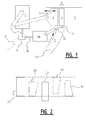
- Figure 1 shows a schematic representation of main inside elements of an agricultural baler.
- the figure 1 shows a baling chamber 1 and a pre-compression chamber 2.
- the pre-compression chamber opens in the baling chamber to push a slice of crop material 3 in a first segment 4 of the baling chamber 1.
- the baling chamber comprises a plunger 5 which is provided for reciprocally moving in the baling chamber.
- the reciprocal movement is indicated by arrow 6.
- the plunger 5 is driven by a plunger driving mechanism 13.
- the connection between the plunger driving mechanism 13 and the plunger 5 is schematically represented by a pair of arms, however other driving mechanisms can be used as well for driving the plunger 5 in the reciprocal movement 6.
- the pre-compression chamber 2 comprises a slice pushing mechanism 12.
- the slice pushing mechanism 12 is driven by a slice pushing driving mechanism 14.
- the slice pushing driving mechanism 14 is mechanically connected to the plunger driving mechanism 13. Such mechanical connection ensures a synchronized movement between the plunger 5 and the slice pushing mechanism 12.
- the plunger 5 moves over at least a part of the first segment 4 of the baling chamber 1. Therefore, for being able to push a slice of crop material 3 into the baling chamber 1, the plunger 5 is preferably somewhere in a withdrawn position in the reciprocal movement. Otherwise the first segment 4 is not open for receiving a slice of crop material 3.
- the pre-compression chamber preferably comprises an inlet 10 and an outlet 11.
- the outlet 11 opens toward the first segment 4 of the baling chamber 1, so that a slice of crop material 3 formed in the pre-compression chamber 2 can be pushed through the outlet 11 into the baling chamber 1.
- the inlet 10 of the pre-compression chamber 2 is preferably connected to crop gathering means (not shown) provided for gathering crop material and pushing the gathered crop material into the pre-compression chamber 2 via the inlet 10.
- the mechanical connection between the plunger driving mechanism 13 and the slice pushing driving mechanism 14 is schematically represented by the elements 15, 16 and 17 in figure 1 .
- top fill An important aspect in the formation of a square bale via the agricultural baler, is the top fill.
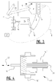
- FIG 2 illustrates some possibilities regarding top fill.
- Top fill is defined as the distribution of crop material over the first segment 4 area at the moment that the plunger hits the slice of crop material in its forward movement.
- slice 31 the crop material is evenly distributed over the complete area of the first segment 4 of the baling chamber 1.
- this ideal situation cannot always be achieved.
- a slice of crop material 3 that is formed in the pre-compression chamber 2 has a density that is too low to keep the slice 3 in shape.
- the effect is that the slice of crop material shrinks in the first segment 4 of the baling chamber 1, thereby resulting in a slice as is shown in figure 2 with reference number 32 or reference number 35.
- a mechanical connection is established between plunger driving mechanism and the slice pushing driving mechanism 14 via respective plunger shaft 15 and slice pushing mechanism shaft 16 which are connected via a coupling means or gearbox 17.
- the gearbox 17 connects the two shafts so that the shafts rotate with respect to one another in a predetermined rotation ratio.
- the rotation ratio is 2, meaning that one shaft rotates two times as fast as the other shaft.
- the rotation ratio is 1, meaning that the shafts rotate at the same speed.
- Other rotation ratios are possible.
- the gearbox 17 is furthermore adapted for adjusting the rotation ratio between the plunger axis 15 and the slice pushing mechanism axis 16, thereby adjusting synchronization between reciprocal plunger movement 6 and the slice pushing movement of the pre-compression chamber 2.
- the controller 9 is adapted to control the gearbox 17 based on an input 8.
- Different sorts of inputs 8 exist that are suitable for controlling the controller 9.
- An operator of the baler can provide an input 8 manually based on visual observations or measurements executed on produced bales. After examining the produced bales, an operator can adjust synchronization based on experience and provide the corresponding input 8 to the controller 9.
- Other input 8 mechanisms include sensors 7, of which figure 3 shows an example. The sensors 7 can be placed at different places inside the baler and provided for measuring different parameters. These parameters can be used, in an example, by a microprocessor to control the controller 9 thereby amending synchronization.
- Figure 4 shows an example of a gearbox 17 that is suitable for adjusting synchronization between a first and a second rotating shaft.
- the gearbox 17 comprises helical input gear 15' and a straight output gear 16'.
- the helical input gear 15' is coupled to the plunger shaft 15 and the straight output gear 16' is coupled to the slice pushing mechanism shaft 16.
- the input gear 15' and output gear 16' are mounted in a frame (not shown) such that the distance between input gear 15' and output gear 16' is fixed.
- the input gear 15' and output gear 16' are connected via an intermediary gear 18 showing two parts.
- a first part comprises a helical gear 19 complementary to the helical input gear 15', and the second part shows a straight gear 20 complementary with the straight output gear 16'.
- the intermediary gear transmits the rotation of the input shaft connected to the input gear 15' directly in a one-to-one ratio to the output shaft connected to the output gear 16'.
- the first part 19 and the second part 20 of the intermediary gear are preferably integrally formed in such a matter that one end of the intermediary gear comprises the helical gear 19 and the opposite end comprises the straight gear 20.
- the helical gear and the straight gear are formed around a single longitudinal axis of the intermediary gear element.
- the helical gear diameter is larger than the straight gear diameter. More preferably, the helical gear diameter is larger than two times the straight gear diameter.
- the intermediary gear element is provided to move along its longitudinal axis between a first and a second position.
- the intermediary gear element is shown in its most leftward position, and can be shifted to the right.
- the relative position of the input gear 15' and the output gear 16' changes.
- synchronization between the input gear 15' and output gear 16' respectively coupled to the plunger driving mechanism and the slice pushing driving mechanism can be amended and fine-tuned while maintaining an overall synchronization (as the shafts are mechanically coupled).
- Such fine-tuning is achieved by moving the intermediary gear element 18 along its longitudinal axis. Such movement is indicated in figure 4 by reference number 21.
- Adjustment of synchronization timing can be directly and positively verified by an easy test.
- rotation of the shafts can be visualised in the form of pulses.
- a pulse is generated.
- this can be measured via an optical sensor and be visualised on a screen.
- a first measurement is conducted when the coupling means 17 are in a first status.
- a second measurement is conducted when the coupling means 17 are in a second status (for example when the intermediary element is moved). If the visualised rotations show a different pattern (different rotation ratio or shifted timing of rotation of one shaft with respect to the other shaft), the synchronization timing is adjusted.
- a planetary gearbox (not shown) can be used to adjust synchronization timing between the plunger shaft 15 and the slice pushing driving mechanism shaft 16.
- a planetary gearbox is known for connecting three shafts. The center wheel, the ring wheel and the planetary wheels form the shaft connecting element. Thereby, the plunger shaft 15 and slice pushing driving mechanism shaft 16 can each be connected to one of the three gear elements of the planetary gearbox.
- a controller can be connected to the third gear of the planetary gearbox.
- the gearbox can be so configured that a standing still controller results in a ratio between input shaft speed and output shaft speed (in the present case the plunger shaft 15 and slice pushing driving mechanism shaft 16) that is fixed and predetermined so that synchronization is achieved.
- the timing of insertion of a slice 3 with respect to the plunger movement 6 can be adjusted and thereby optimized. Also the speed of pushing the slice into the first segment of the baling chamber can be adjusted and optimized.
- Figure 5 shows two graphical representations of the slice pushing movement.
- the lower graph shows the movement that the slice pushing mechanism tip makes in time, and shows on the horizontal axis the horizontal movement in millimeters and on the vertical axis the vertical movement in millimeters.
- the tip is displaced in the direction indicated by arrow 29 and grasps behind the slice to push the slice through the outlet into the baling chamber.
- the pushing movement is indicated by reference number 27.
- the tip withdraws, and in the withdrawn position, moves back to the starting point 28 where the tip can push a new slice in a subsequent period.
- the upper part of figure 5 shows the transmission of rotational movement between the plunger shaft and the slice pushing mechanism shaft over the time.
- the slice pushing period takes 1.2 seconds, meaning that every 1.2 second a new slice of crop material is pushed into the baling chamber.
- a rotation is transmitted from one to the other shaft in a flat manner as is indicated by reference number 24.
- This rotation results in a slice pushing mechanism tip moving along the path 26 with a constant speed (constant speed meaning that in every period, in every sub-segment of the movement, the tip follows the path with an identical distance over time ratio).
- the speed of the segment 27 of the path of movement 26 cannot be adjusted.
- the synchronization can be adjusted.
- An example of an adjusted synchronization is indicated with reference number 25.
- the first part of the period is speeded up with respect to the second part of the period.
- the slice pushing mechanism tip moves faster over the segment 27 of the movement path 26 than over the rest of the movement path.
- the timing of arrival of the slice 3 in the first segment 4 of the baling chamber 1 is adjusted.
- the gearbox 17 comprises an actuator 40 that is steerable via the controller 9.
- the controller 9 is operationally connected to input means such as a slice presence detecting sensor 7.
- the actuator 40 is preferably coupled to the gearbox in such a manner that the relative position of the plunger shaft with respect to the slice pushing mechanism shaft is adjustable.
- the actuator is coupled to the intermediary gear element to move the intermediary gear element along it longitudinal axis.
- the actuator is coupled to the third of the three gear elements, so that a rotation of the actuator changes the relative position of the plunger shaft (connected to a first of the three gear elements) and the slice pushing driving mechanism shaft (connected to a second of the three gear elements).
- the actuator is steerable by the controller, which thereby controls the relative position of the plunger shaft 15 with respect to the slice pushing driving mechanism shaft 16.
- the controller comprises a manual input means, an electrical circuit or an electronic circuit or a programmable electronic circuit or a combination of the above, so that the controller can control the actuator 40 based on one or more input signals.
- the controller can comprise an open control loop, or a closed control loop, or a control loop comprising feed forward control commands, or a combination of the above.
- the input 8 is formed by a sensor 7 that is placed in the first segment 4 of the baling chamber 1.
- the sensor 7 is adapted to measure a presence of a slice 3 in the first segment 4 of the baling chamber 1. Therefore this sensor is referred to as slice presence detecting sensor.
- Such slice presence detecting sensor 7 can be formed in different manners such as ultrasonic sensor, infrared sensor, contact sensor, optical sensor or other known sensors.
- the slice presence detecting sensor 7 is formed as a force sensor adapted to measure a contact force. With such force sensor, not only the presence of the slice can be measured, but also the force with which the slice arrives at the sensor can be measured. Such force can be indicative for slice deformation (a slice arriving at the sensor with a high force undergoes a high acceleration which can result in a deformation of the slice).
- the slice presence detecting sensor 7 is in an example operationally coupled 8 to a controller 9.
- the controller 9 is adapted to adjust synchronization between the reciprocal plunger movement 6 and the slice pushing movement of the pre-compression chamber 2.
- Figure 3 shows an alternative configuration of a baling chamber 1 and a pre-compression chamber 2.
- multiple slice presence detecting sensors are provided in the first segment 4 of the baling chamber 1, each of the sensors being mounted at a different height in the first segment 4 of the baling chamber 1.
- the slice presence detecting sensors 7 are preferably mounted in at least one of the side walls of the baling chamber 1. Having multiple slice presence detecting sensors at different heights in the first segment 4 of the baling chamber 1 allows to deduce not only an arrival of the slice, but also a speed of the slice, and where at least three sensors are provided, an acceleration or deceleration of the slice in the first segment 4 of the baling chamber 1. This speed and acceleration/deceleration information can be further used by the controller 9 to adjust the synchronization between the reciprocal movement of the plunger and the slice pushing of the pre-compression chamber 2.
- Figure 3 also shows a gearbox 17 having 3 inputs being the plunger shaft 15, the slice pushing mechanism shaft 16 and an actuator 40 shaft.
- the actuator 40 shaft is controlled by the controller 9 and is provided to adjust synchronization timing between the plunger shaft 15 and the slice pushing mechanism shaft 16.
Landscapes
- Life Sciences & Earth Sciences (AREA)
- Environmental Sciences (AREA)
- Retarders (AREA)
Abstract
Description
- The present invention relates to an agricultural baler. Preferably the present invention relates to a square agricultural baler, which is provided for gathering crop material, forming slices of crop material from the gathered crop material, and pressing square bales from the slices.
- Agricultural balers typically comprise two main parts used in the formation of the bales, being a pre-compression chamber and a baling chamber. Crop material is gathered and pushed into the pre-compression chamber, where a slice of crop material is formed. Pre-compression chamber is linked to the baling chamber in such a manner that the slice of crop material can periodically be transferred into the baling chamber. In the baling chamber, a plunger reciprocally moves, thereby pressing a square bale from subsequently feeded slices.
- The plunger movement is powered via a main shaft driven by a motor. Thereby, the motor can be a part of the baler, or can be a part of e.g. the tractor connected to the baler via a power take-off (PTO). In practice, this reciprocal movement of the plunger is often considered the most dominant movement in the baler, dominant meaning that other movements are made relative to this movement of the plunger. The reason is that the plunger movement requires the highest force (highest relative to other forces needed for operating the baler). Off all movements in the baler, the movement of the plunger shows the highest inertia.
- The pre-compression chamber is adapted for receiving gathered crop material. To this end, the pre-compression chamber shows an inlet. The pre-compression chamber furthermore shows an outlet towards the baling chamber. Between the inlet and the outlet, a channel is defined in which crop material can gather into a slice of crop material. The pre-compression chamber comprises a slice pushing mechanism provided for pushing a slice of crop material formed in the pre-compression chamber through the outlet of the pre-compression chamber into the baling chamber. The sliced crop material is typically pushed in a first segment of the baling chamber. First segment is typically located directly behind the plunger (the plunger being in the withdrawn position). Thereby the slice of crop material is pushed in the baling chamber, after which the plunger can propel the crop material into the baling chamber, thereby pushing the most recently entered slice into the baling chamber, making it a part of the square bale.
- The pre-compression chamber comprises, for the purpose of pushing the slice into the baling chamber, a slice pushing mechanism. Different types of slice pushing mechanisms are known, among which fingers grasping behind the slice and pushing the slice through the outlet, or a set of conveyer belts in between which the slice is formed, and which conveyer belts are driven to push the slice through the outlet.
- The slice pushing mechanism is driven via a driving mechanism that is operationally linked to the plunger driving mechanism. A synchronized movement between the slice pushing mechanism and the plunger is needed to ensure a proper operation of the baler. Namely, only when the plunger is withdrawn, a slice can be pushed in the baling chamber. In practice, different synchronization types are possible among which a one/one synchronization, meaning that every withdrawal of the plunger a new slice is entered into the baling chamber, or a one/two synchronization, meaning that every other withdrawal of the plunger a new slice is entered, thus the plunger moves forth and back two times for each slice. Other synchronization timing such as one/three, one/four,... are also possible.
- Synchronization is in practice realized by mechanically linking the plunger driving mechanism and the slice pushing driving mechanism. Such mechanical link ensures proper synchronization, as the slice pushing mechanism is mechanically driven by the plunger movement, it cannot move out of synchronization.
- A drawback relates to so called top fill. Top fill is a measure for the uniformity of the slice after it has entered the first segment of the baling chamber. It will be recognized that a non uniform fill, for example where the lower part of the first segment is more dense than an upper part, results in an inferior bale. Such top fill has an effect that a bale is high dense at the lower end, and not dense at the top, resulting in an unstable bale that is likely to show a substantial deviation from the ideal square form. Such bale will bend like a banana resulting in a weirdly shaped bale. A negative top fill also results in a substantial wear of the plunger and baling chamber, as forces are not equally transmitted. The plunger will feel a substantially high resistance at the lower part of the plunger compared to the upper part resistance of the plunger. This will create a torque force exerted to the plunger which has to be borne by the plunger driving mechanism. When the ideal top fill can be obtained, a bale can be formed with nearly ideal outer dimensions and shape, and excessive wear on the baler mechanism can be avoided. In prior art balers, the ideal top fill is obtained by controlling the slice forming process in the pre-compression chamber. By obtaining a slice in which the crop material is evenly spread over the slice, after which the slice is pushed into the baling chamber, an acceptable top fill can be obtained.
- A drawback of the existing top fill controlling mechanisms is that a deviation of the top fill can still occur depending on the baling speed and the type of crop material (hay, straw, silage, ...).
- It is an object of the present invention to provide a baler where top fill is controllable in a more accurate manner.
- To this end, the invention provides an agricultural baler comprising a baling chamber with a plunger that is provided to reciprocally move in the baling chamber, the baler further comprising a pre-compression chamber with a slice pushing mechanism provided for periodically pushing a slice of crop material into the baling chamber, the plunger and the pushing mechanism being mechanically linked via their respective driving systems to ensure synchronization, wherein coupling means are mounted in the mechanical link, the coupling means being provided to adjust a synchronization timing.
- In prior art balers, a mechanical connection is often provided between the plunger driving mechanism and the slice pushing driving mechanism. This mechanical connection ensures a correct synchronized movement between the plunger and the crop pushing mechanism. This prevents the crop pushing mechanism from pushing a slice of crop material into the baling chamber if the baling chamber is not ready to receive the slice crop material (for example when the plunger is in its extended position thereby closing off the first segment of the baling chamber). By providing a coupling element in the mechanical connection, the synchronization timing can be adjusted. Thereby, the synchronization can be fine-tuned meaning that the moment of arrival of the slice of crop material into the first segment of the baling chamber can be somewhat shifted. Thereby, the mechanical connection is maintained ensuring a correct synchronization (in the broad sense of synchronization) while enabling the controller to adjust the synchronization (thereby obtaining a fine-tuned synchronization). By controlling the moment of arrival of the slice of crop material in the baling chamber, the top-fill can be influenced and thereby optimized. As a result, via the coupling element the top-fill is controllable.
- Preferably, the coupling means are formed as an intermediary element linking two rotating shafts, a first one connected to a plunger driving system and a second one connected to a pushing mechanism driving system. Mechanically linking the plunger with the pre-compression chamber's pushing mechanism can be achieved via linking their respective driving systems. By providing a rotating shaft mechanically linked to the plunger driving system and providing a rotating shaft mechanically linked to the pushing mechanism driving system side, these two rotating shafts can be connected via an intermediary linking element. Such link provides a reliable connection and is easy to implement on an agricultural baler.
- Preferably, a position of the intermediary element determines the synchronization timing. By steering the intermediary element position, the top-fill is controllable. The position can be steered manually or via an actuator or via other known mechanism. The desired position can be determined manually or automatically so that the synchronization timing can be amended and thereby the top-fill can be controlled.
- Preferably, the intermediary element is movable to adjust the relative position of the two rotating shafts with respect to each other thereby adjusting the synchronization timing, more preferably the intermediary element is movable between a first position and a second position, wherein the relative angular position of the two rotating shafts with respect to each other when the intermediary element is in the first position, is different from the relative angular position of the two rotating shafts with respect to each other when the intermediary element is in the second position. Multiple mechanisms are known wherein the intermediary elements position is determining for the angular position of the shafts linked via the intermediary position. By amending the relative angular position, the timing of movement of the plunger can be amended with respect to the timing of movement of the pushing mechanism. Thereby, synchronization timing can be adjusted and top-fill can be controlled.
- According to one embodiment, the intermediary element is formed as a planetary gearbox having an outer gear, at least two planet gears and a central gear, whereby the plunger driving system is coupled to one of the outer gear, two planet gears and central gear, and whereby the pushing mechanism driving system is coupled to another of the outer gear, two planet gears and central gear, and whereby an actuator is coupled to the yet another of the outer gear, two planet gears and central gear to displace the latter thereby adjusting the relative position of the plunger driving system and the pushing mechanism driving system. A planetary gearbox is known for linking three rotational movements (respectively via the central gear, the planet gears and the outer gear). Therefore the planetary gearbox can be used in the present case to link the plunger driving mechanism, the pushing mechanism driving system, and an actuator. Thereby, when the actuator stands still, there is a constant predictable link between rotational speed of the plunger driving mechanism and the pushing mechanism driving system, meaning that the relative movement of one with respect to the other is fixed. Thereby, because of the fixed relative movement, the synchronization timing is also fixed. By operating the actuator, connected to the planetary gearbox, the relative position of the plunger driving mechanism and the pushing mechanism driving system changes. Thereby, synchronization optimization is made possible. A skilled person can, based on the principles explained in this disclosure, test and/or determine several planetary gearbox constructions, and can test and/or determine the influence of the actuator to the synchronization timing.
- According to a second embodiment, the intermediary element has a first end being provided with a straight gear and a second end being provided with a helical gear. Thereby, a two part gearbox is formed whereby one end is connected via a straight gear coupling and another end is connected via a helical gear coupling. Such two part gearbox is known in the art for amending the relative position of two shafts while connecting the shafts in a rotational movement. When the two part gearbox is in a fixed position, the two shafts are directly connected to one another. Thereby, rotational movement and forces can be transmitted from one shaft to another. By displacing the gearbox along its longitudinal axis, the relative position of the two shafts is amended. This is because the one end (via the straight gear coupling) remains its axial position with respect to the shaft connected to that one end, while the axial position of the second part (connected via the helical gear coupling) is changed with respect to the second shaft connected to that other end. Thereby, synchronization can be adjusted and amended synchronization timing can be obtained via such two part gearbox. A displacement of an intermediary element with straight gear and helical gear, has as a result that the straight gear part does not change relative angular position with the shaft it is connected to while the helical gear part does change relative angular position with the shaft it is connected to. Thereby, relative angular position can be amended by amending the intermediary element position. By amending the relative angular position, the synchronization timing can be amended and consequently the top-fill can be controlled.
- Preferably, the intermediary element is mounted between an input gear and an output gear, whereby the input gear comprises a helical inner shape matching with the helical gear and whereby the output gear comprises a straight inner shape matching with the straight gear, the input gear being mounted at a fixed distance with respect to the output gear, so that moving the intermediary element or input gear in the direction of its axis results in a change of rotational position of the input gear with respect to the output gear. Because the distance between the input gear and the output gear is fixed, a movement of the intermediary element results in an equal movement of that element with respect to both of the input and output gear. As a result, the helical gear will rotate the input gear with respect to the output gear, which is connected to the intermediary element via the straight gear. Thereby, relative angular position of input gear with respect to output gear can be amended thus amending the synchronization thus controlling the top-fill.
- Preferably, the input gear is connected to one of the plunger driving system and the pushing mechanism driving system and the output gear is connected to the other of the plunger driving system and the pushing mechanism driving system. Thereby, the relative angular position of plunger driving system and pushing mechanism driving system can be amended thus amending the top-fill.
- Preferably, an actuator is connected to the intermediary element or input gear for displacing the latter along its longitudinal axis thereby amending the relative angular position of the input gear with respect to the output gear. The actuator can be electrically or hydraulically powered or mechanically coupled with an external power source. The actuator allows an operator to adjust the synchronization from a distance. Furthermore, an actuator allows implementing a repetitive adjusting of the synchronization, whereby for each running cycle of the plunger or slice pushing mechanism a predetermined adjusted synchronization pattern can be obtained.
- Preferably the coupling means comprise a controlling mechanism for repetitive control of the coupling means. More preferably the controlling mechanism is provided for repetitive control of the intermediary element. Thereby the predetermined adjusted synchronization pattern can be obtained. Such synchronization pattern allows to adjust timing and moving speed of the slice pushing mechanism at predetermined sectors of the moving cycle.
- Preferably the actuator is connected to said controlling mechanism to be controllable in a repetitive movement. Such configuration allows the operator to implement and execute a repetitive synchronization adjustment.
- The invention will now be described in more details with respect to the drawings illustrating some preferred embodiments of the invention. In the drawings:
-
figure 1 shows a schematic representation of a baling chamber and pre-compression chamber; -
figure 2 shows some top-fill possibilities; -
figure 3 shows an alternative schematic representation of a baling chamber and pre-compression chamber; -
figure 4 shows a gearbox suitable for coupling the baling chamber movement and the pre-compression chamber movement; and -
figure 5 shows the influence of the gearbox in the movement of the pre-compression chamber elements. - In the drawings a same reference number has been allocated to a same or analogous element.
-
Figure 1 shows a schematic representation of main inside elements of an agricultural baler. Thefigure 1 shows a balingchamber 1 and apre-compression chamber 2. The pre-compression chamber opens in the baling chamber to push a slice ofcrop material 3 in a first segment 4 of the balingchamber 1. - The baling chamber comprises a
plunger 5 which is provided for reciprocally moving in the baling chamber. The reciprocal movement is indicated byarrow 6. To this end, theplunger 5 is driven by aplunger driving mechanism 13. The connection between theplunger driving mechanism 13 and theplunger 5 is schematically represented by a pair of arms, however other driving mechanisms can be used as well for driving theplunger 5 in thereciprocal movement 6. - The
pre-compression chamber 2 comprises aslice pushing mechanism 12. Theslice pushing mechanism 12 is driven by a slice pushingdriving mechanism 14. Preferably, the slice pushingdriving mechanism 14 is mechanically connected to theplunger driving mechanism 13. Such mechanical connection ensures a synchronized movement between theplunger 5 and theslice pushing mechanism 12. - It will be clear that synchronization between the
slice pushing mechanism 12 of the pre-compression chamber and thereciprocal movement 6 of theplunger 5 is important for a correct operation of the baler. In the reciprocal movement of theplunger 5, the plunger moves over at least a part of the first segment 4 of the balingchamber 1. Therefore, for being able to push a slice ofcrop material 3 into the balingchamber 1, theplunger 5 is preferably somewhere in a withdrawn position in the reciprocal movement. Otherwise the first segment 4 is not open for receiving a slice ofcrop material 3. - The pre-compression chamber preferably comprises an
inlet 10 and anoutlet 11. Theoutlet 11 opens toward the first segment 4 of the balingchamber 1, so that a slice ofcrop material 3 formed in thepre-compression chamber 2 can be pushed through theoutlet 11 into the balingchamber 1. Theinlet 10 of thepre-compression chamber 2 is preferably connected to crop gathering means (not shown) provided for gathering crop material and pushing the gathered crop material into thepre-compression chamber 2 via theinlet 10. - The mechanical connection between the
plunger driving mechanism 13 and the slice pushingdriving mechanism 14 is schematically represented by theelements figure 1 . - An important aspect in the formation of a square bale via the agricultural baler, is the top fill.
-
Figure 2 illustrates some possibilities regarding top fill. Top fill is defined as the distribution of crop material over the first segment 4 area at the moment that the plunger hits the slice of crop material in its forward movement. In an ideal situation, as is illustrated byslice 31, the crop material is evenly distributed over the complete area of the first segment 4 of the balingchamber 1. However, this ideal situation cannot always be achieved. At lower baling speed, it is possible that a slice ofcrop material 3 that is formed in thepre-compression chamber 2 has a density that is too low to keep theslice 3 in shape. The effect is that the slice of crop material shrinks in the first segment 4 of the balingchamber 1, thereby resulting in a slice as is shown infigure 2 withreference number 32 orreference number 35. Pressing a bale with slices formed like that, results in an uneven distribution of load to the plunger and results in bales having shapes that deviate from the ideal rectangular shape. In another case, a wrong synchronization between the slice pushing mechanism and the plunger could result in a slice that is not yet completely pushed in the first segment of the baling chamber when the plunger hits the slice, or has already fallen back (due to gravity) because the slice pushing mechanism withdrew too early. In such situation, a slice as is shown infigure 2 byreference number 33 is compressed by the plunger. Compressing such a slice again results in the above described problems. In fast working balers, another problem might arise where the slice pushing mechanism pushes the slice in the first segment of the baling chamber with such force that the slice deforms because it bumps into the top wall of the balingchamber 1. Such situation results in a slice as is shown infigure 2 withreference number 34. Again, such slice results in excessive wear of the baler elements because of unbalanced load, and results in bad bales. - In the example of
figure 1 , a mechanical connection is established between plunger driving mechanism and the slice pushingdriving mechanism 14 viarespective plunger shaft 15 and slice pushingmechanism shaft 16 which are connected via a coupling means orgearbox 17. Thegearbox 17 connects the two shafts so that the shafts rotate with respect to one another in a predetermined rotation ratio. For example the rotation ratio is 2, meaning that one shaft rotates two times as fast as the other shaft. In another example, the rotation ratio is 1, meaning that the shafts rotate at the same speed. Other rotation ratios are possible. Thegearbox 17 is furthermore adapted for adjusting the rotation ratio between theplunger axis 15 and the slice pushingmechanism axis 16, thereby adjusting synchronization betweenreciprocal plunger movement 6 and the slice pushing movement of thepre-compression chamber 2. Thecontroller 9 is adapted to control thegearbox 17 based on an input 8. Different sorts of inputs 8 exist that are suitable for controlling thecontroller 9. An operator of the baler can provide an input 8 manually based on visual observations or measurements executed on produced bales. After examining the produced bales, an operator can adjust synchronization based on experience and provide the corresponding input 8 to thecontroller 9. Other input 8 mechanisms include sensors 7, of whichfigure 3 shows an example. The sensors 7 can be placed at different places inside the baler and provided for measuring different parameters. These parameters can be used, in an example, by a microprocessor to control thecontroller 9 thereby amending synchronization. -
Figure 4 shows an example of agearbox 17 that is suitable for adjusting synchronization between a first and a second rotating shaft. Thegearbox 17 comprises helical input gear 15' and a straight output gear 16'. In the example offigure 4 andfigure 1 , the helical input gear 15' is coupled to theplunger shaft 15 and the straight output gear 16' is coupled to the slice pushingmechanism shaft 16. The input gear 15' and output gear 16' are mounted in a frame (not shown) such that the distance between input gear 15' and output gear 16' is fixed. The input gear 15' and output gear 16' are connected via anintermediary gear 18 showing two parts. A first part comprises ahelical gear 19 complementary to the helical input gear 15', and the second part shows astraight gear 20 complementary with the straight output gear 16'. Thereby, in a non-moving position, the intermediary gear transmits the rotation of the input shaft connected to the input gear 15' directly in a one-to-one ratio to the output shaft connected to the output gear 16'. Thefirst part 19 and thesecond part 20 of the intermediary gear are preferably integrally formed in such a matter that one end of the intermediary gear comprises thehelical gear 19 and the opposite end comprises thestraight gear 20. The helical gear and the straight gear are formed around a single longitudinal axis of the intermediary gear element. Preferably the helical gear diameter is larger than the straight gear diameter. More preferably, the helical gear diameter is larger than two times the straight gear diameter. - The intermediary gear element is provided to move along its longitudinal axis between a first and a second position. In
figure 4 , the intermediary gear element is shown in its most leftward position, and can be shifted to the right. By moving the intermediary gear element along its longitudinal axis, the relative position of the input gear 15' and the output gear 16' changes. Thereby, synchronization between the input gear 15' and output gear 16' respectively coupled to the plunger driving mechanism and the slice pushing driving mechanism, can be amended and fine-tuned while maintaining an overall synchronization (as the shafts are mechanically coupled). Such fine-tuning is achieved by moving theintermediary gear element 18 along its longitudinal axis. Such movement is indicated infigure 4 byreference number 21. In a situation with a non-moving intermediary element, the rotation ratio between input gear 15' and output gear 16' is fixed to a 1 on 1 ratio. By moving the intermediary element along its longitudinal axis, a rotation of the input gear 15' with respect to the output gear 16' is induced, which has as a result that the rotation ratio, at least during movement of the intermediary element, deviates from the fixed 1 on 1 ratio. Thereby, synchronization timing is adjusted. - Adjustment of synchronization timing can be directly and positively verified by an easy test. By placing a mark at the outer surface of each of the input shaft and output shaft (the mark being for example in the form of a white dot), rotation of the shafts can be visualised in the form of pulses. Each time the dot passes a predetermined location, a pulse is generated. As an example, this can be measured via an optical sensor and be visualised on a screen. A first measurement is conducted when the coupling means 17 are in a first status. A second measurement is conducted when the coupling means 17 are in a second status (for example when the intermediary element is moved). If the visualised rotations show a different pattern (different rotation ratio or shifted timing of rotation of one shaft with respect to the other shaft), the synchronization timing is adjusted.
- Alternatively to a gearbox as shown in
figure 4 , a planetary gearbox (not shown) can be used to adjust synchronization timing between theplunger shaft 15 and the slice pushingdriving mechanism shaft 16. A planetary gearbox is known for connecting three shafts. The center wheel, the ring wheel and the planetary wheels form the shaft connecting element. Thereby, theplunger shaft 15 and slice pushingdriving mechanism shaft 16 can each be connected to one of the three gear elements of the planetary gearbox. A controller can be connected to the third gear of the planetary gearbox. The gearbox can be so configured that a standing still controller results in a ratio between input shaft speed and output shaft speed (in the present case theplunger shaft 15 and slice pushing driving mechanism shaft 16) that is fixed and predetermined so that synchronization is achieved. A rotation of the controller, rotating the third gear of the planetary gearbox, amends the relative position of the input shaft and output shaft, thereby adjusting the synchronization. A skilled person, given the information above, can configure a planetary gearbox in different manners to serve the purpose of the present invention. - By adjusting synchronization between the
reciprocal plunger movement 6 and the slice pushing movement of theslice pushing mechanism 12, the timing of insertion of aslice 3 with respect to theplunger movement 6 can be adjusted and thereby optimized. Also the speed of pushing the slice into the first segment of the baling chamber can be adjusted and optimized. -
Figure 5 shows two graphical representations of the slice pushing movement. The lower graph shows the movement that the slice pushing mechanism tip makes in time, and shows on the horizontal axis the horizontal movement in millimeters and on the vertical axis the vertical movement in millimeters. Starting atpoint 28, the tip is displaced in the direction indicated byarrow 29 and grasps behind the slice to push the slice through the outlet into the baling chamber. The pushing movement is indicated byreference number 27. In the rest of themovement 26, the tip withdraws, and in the withdrawn position, moves back to thestarting point 28 where the tip can push a new slice in a subsequent period. The upper part offigure 5 shows the transmission of rotational movement between the plunger shaft and the slice pushing mechanism shaft over the time. In the figure, as an example, the slice pushing period takes 1.2 seconds, meaning that every 1.2 second a new slice of crop material is pushed into the baling chamber. Using a fixed connection between theplunger shaft 15 and the slice pushingmechanism shaft 16, a rotation is transmitted from one to the other shaft in a flat manner as is indicated byreference number 24. This rotation results in a slice pushing mechanism tip moving along thepath 26 with a constant speed (constant speed meaning that in every period, in every sub-segment of the movement, the tip follows the path with an identical distance over time ratio). Thereby, the speed of thesegment 27 of the path ofmovement 26 cannot be adjusted. Using a gearbox as described above to connect the plunger shaft and the slice pushing driving mechanism shaft, the synchronization can be adjusted. An example of an adjusted synchronization is indicated withreference number 25. In this example, the first part of the period is speeded up with respect to the second part of the period. Thereby, the slice pushing mechanism tip moves faster over thesegment 27 of themovement path 26 than over the rest of the movement path. As a result, the timing of arrival of theslice 3 in the first segment 4 of the balingchamber 1 is adjusted. - Preferably the
gearbox 17 comprises anactuator 40 that is steerable via thecontroller 9. Thecontroller 9 is operationally connected to input means such as a slice presence detecting sensor 7. Theactuator 40 is preferably coupled to the gearbox in such a manner that the relative position of the plunger shaft with respect to the slice pushing mechanism shaft is adjustable. In the example of the gearbox offigure 4 , the actuator is coupled to the intermediary gear element to move the intermediary gear element along it longitudinal axis. In the example of the planetary gearbox, the actuator is coupled to the third of the three gear elements, so that a rotation of the actuator changes the relative position of the plunger shaft (connected to a first of the three gear elements) and the slice pushing driving mechanism shaft (connected to a second of the three gear elements). The actuator is steerable by the controller, which thereby controls the relative position of theplunger shaft 15 with respect to the slice pushingdriving mechanism shaft 16. - The controller comprises a manual input means, an electrical circuit or an electronic circuit or a programmable electronic circuit or a combination of the above, so that the controller can control the
actuator 40 based on one or more input signals. The controller can comprise an open control loop, or a closed control loop, or a control loop comprising feed forward control commands, or a combination of the above. - In an example, the input 8 is formed by a sensor 7 that is placed in the first segment 4 of the baling
chamber 1. The sensor 7 is adapted to measure a presence of aslice 3 in the first segment 4 of the balingchamber 1. Therefore this sensor is referred to as slice presence detecting sensor. Such slice presence detecting sensor 7 can be formed in different manners such as ultrasonic sensor, infrared sensor, contact sensor, optical sensor or other known sensors. Preferably, the slice presence detecting sensor 7 is formed as a force sensor adapted to measure a contact force. With such force sensor, not only the presence of the slice can be measured, but also the force with which the slice arrives at the sensor can be measured. Such force can be indicative for slice deformation (a slice arriving at the sensor with a high force undergoes a high acceleration which can result in a deformation of the slice). - The slice presence detecting sensor 7 is in an example operationally coupled 8 to a
controller 9. Thecontroller 9 is adapted to adjust synchronization between thereciprocal plunger movement 6 and the slice pushing movement of thepre-compression chamber 2. -
Figure 3 shows an alternative configuration of a balingchamber 1 and apre-compression chamber 2. In the example offigure 3 , multiple slice presence detecting sensors are provided in the first segment 4 of the balingchamber 1, each of the sensors being mounted at a different height in the first segment 4 of the balingchamber 1. The slice presence detecting sensors 7 are preferably mounted in at least one of the side walls of the balingchamber 1. Having multiple slice presence detecting sensors at different heights in the first segment 4 of the balingchamber 1 allows to deduce not only an arrival of the slice, but also a speed of the slice, and where at least three sensors are provided, an acceleration or deceleration of the slice in the first segment 4 of the balingchamber 1. This speed and acceleration/deceleration information can be further used by thecontroller 9 to adjust the synchronization between the reciprocal movement of the plunger and the slice pushing of thepre-compression chamber 2. -
Figure 3 also shows agearbox 17 having 3 inputs being theplunger shaft 15, the slice pushingmechanism shaft 16 and anactuator 40 shaft. As described above, theactuator 40 shaft is controlled by thecontroller 9 and is provided to adjust synchronization timing between theplunger shaft 15 and the slice pushingmechanism shaft 16. - It will be clear that different combination can be made of baler elements which examples are given in the present description. Also alternative gearboxes could be developed based on the principles disclosed in this document which allow to adjust synchronization timing. Therefore, it is emphasized that the examples described and the figures shown in support of the description are not intended to limit the invention. The scope of the invention shall be solely defined in claims.
- In the above description, different embodiments have been described that allow adjusting the timing of arrival of a slice in the first segment 4 of the baling chamber. By adjusting the timing, referring back to
figure 2 , situations as indicated byreference number 33 can be avoided. Furthermore, deviation of the slice with respect to the ideal shape 31 (deviation such as indicated withreference number reciprocal plunger movement 6 and the slice pushing movement of thepre-compression chamber 2 implies that at least one of the slice pushing speed and slice pushing timing is controllable and can be amended.
Claims (10)
- An agricultural baler comprising a baling chamber (1) with a plunger (5) that is provided to reciprocally move in the baling chamber, the baler further comprising a pre-compression chamber (2) with a slice pushing mechanism (12) provided for periodically pushing a slice (3) of crop material into the baling chamber, the plunger (5) and the slice pushing mechanism (12) being mechanically linked via their respective driving systems (13,14) to ensure synchronization, the coupling means (17) are formed as an intermediary element (17) linking two rotating shafts (15,16), a first one (15) connected to a plunger driving system (13) and a second one (16) connected to a slice pushing driving mechanism (14), the coupling means are mounted in the mechanical link and being provided to adjust a synchronization timing, characterised in that the intermediary element (17) is movable between a first position and a second position, wherein the relative angular position of the two rotating shafts (15,16) with respect to each other when the intermediary element (17) is in the first position, is different from the relative angular position of the two rotating shafts (15,16) with respect to each other when the intermediary element (17) is in the second position.
- The agricultural baler of claim 1, wherein a position of the intermediary element (17) determines the synchronization timing.
- The agricultural baler according to any one of the claims 1 or 2, wherein the intermediary element (17) is movable to adjust the relative position of the two rotating shafts (15,16) with respect to each other thereby adjusting the synchronization timing.
- The agricultural baler of any one of the previous claims, wherein the intermediary element (17) is formed as a planetary gearbox having an outer gear, at least two planet gears and a central gear, whereby the plunger driving system (13) is coupled to one of the outer gear, two planet gears and central gear, and whereby the slice pushing driving mechanism (14) is coupled to another of the outer gear, two planet gears and central gear, and whereby an actuator (40) is coupled to the yet another of the outer gear, two planet gears and central gear to displace the latter thereby adjusting the relative position of the plunger driving system (13) and the slice pushing driving mechanism (14).
- The agricultural baler according to any one of the claims 1-3, wherein the intermediary element (17) has a first end being provided with a straight gear (20) and a second end being provided with a helical gear (19).
- The agricultural baler according to claim 5, wherein the intermediary element (17) is mounted between an input gear (15') and an output gear (16'), whereby the input gear (15') comprises a helical inner shape matching with the helical gear (19) and whereby the output gear (16') comprises a straight inner shape matching with the straight gear (20), the input gear (15') being mounted at a fixed distance with respect to the output gear (16'), so that moving the intermediary element (17) or input gear (15') in the direction of its axis results in a change of rotational position of the input gear (15') with respect to the output gear (16').
- The agricultural baler according to claim 6, wherein the input gear (15') is connected to one of the plunger driving system (13) and the pushing mechanism driving system (14) and the output gear (16') is connected to the other of the plunger driving system (13) and the pushing mechanism driving system (14).
- The agricultural baler according to claim 5 or 6, whereby an actuator (40) is connected to the intermediary element (17) or input gear (15') for displacing the latter along its longitudinal axis thereby amending the relative angular position of the input gear (15') with respect to the output gear (16').
- The agricultural baler according to any one of the previous claims, wherein the coupling means comprises a controlling mechanism (9) for repetitive control of the coupling means (17).
- The agricultural baler according to claim 4 or claim 8 and claim 9, whereby the actuator (40) is connected to said controlling mechanism (9) to be controllable in a repetitive movement.
Applications Claiming Priority (1)
| Application Number | Priority Date | Filing Date | Title |
|---|---|---|---|
| BE2015/5232A BE1022680B1 (en) | 2015-04-10 | 2015-04-10 | Connector between plunger and pre-compression chamber |
Publications (2)
| Publication Number | Publication Date |
|---|---|
| EP3078257A1 true EP3078257A1 (en) | 2016-10-12 |
| EP3078257B1 EP3078257B1 (en) | 2020-06-10 |
Family
ID=53800783
Family Applications (1)
| Application Number | Title | Priority Date | Filing Date |
|---|---|---|---|
| EP16164330.9A Active EP3078257B1 (en) | 2015-04-10 | 2016-04-07 | Plunger and pre-compression chamber link |
Country Status (3)
| Country | Link |
|---|---|
| US (1) | US10426096B2 (en) |
| EP (1) | EP3078257B1 (en) |
| BE (1) | BE1022680B1 (en) |
Cited By (4)
| Publication number | Priority date | Publication date | Assignee | Title |
|---|---|---|---|---|
| IT201700048947A1 (en) * | 2017-05-05 | 2018-11-05 | Cnh Ind Italia Spa | AGRICULTURAL SYSTEM PROVIDED WITH A SQUARED BALING PACKING MACHINE CONTROLLED BY MEANS OF A CONTINUOUS CHANGE |
| EP3563662A1 (en) * | 2018-05-04 | 2019-11-06 | CNH Industrial Belgium N.V. | Intelligent baling |
| EP4331346A1 (en) | 2022-08-17 | 2024-03-06 | Kuhn-Geldrop B.V. | Square baler |
| EP4421343A1 (en) | 2022-10-19 | 2024-08-28 | Kuhn-Geldrop B.V. | One turn coupling |
Families Citing this family (2)
| Publication number | Priority date | Publication date | Assignee | Title |
|---|---|---|---|---|
| DE102023108278A1 (en) * | 2023-03-31 | 2024-10-02 | Deere & Company | Baler and method for operating a baler |
| EP4727337A1 (en) * | 2023-06-19 | 2026-04-22 | Agco Corporation | Agricultural baler |
Citations (3)
| Publication number | Priority date | Publication date | Assignee | Title |
|---|---|---|---|---|
| DE19531240A1 (en) * | 1995-08-25 | 1997-02-27 | Same Spa | Baler, especially self-propelled large baler |
| DE19627397A1 (en) * | 1996-07-06 | 1997-10-02 | Krone Bernhard Gmbh Maschf | Agricultural baling machine towed by tractor |
| WO2015028524A1 (en) * | 2013-08-27 | 2015-03-05 | Cnh Industrial Belgium Nv | Stuffer trigger system for an agricultural baler |
Family Cites Families (1)
| Publication number | Priority date | Publication date | Assignee | Title |
|---|---|---|---|---|
| DE19709604A1 (en) * | 1997-03-08 | 1998-09-10 | Claas Usines France | Method and device for fine adjustment of motion sequences on big balers |
-
2015
- 2015-04-10 BE BE2015/5232A patent/BE1022680B1/en not_active IP Right Cessation
-
2016
- 2016-04-07 EP EP16164330.9A patent/EP3078257B1/en active Active
- 2016-04-08 US US15/094,692 patent/US10426096B2/en active Active
Patent Citations (3)
| Publication number | Priority date | Publication date | Assignee | Title |
|---|---|---|---|---|
| DE19531240A1 (en) * | 1995-08-25 | 1997-02-27 | Same Spa | Baler, especially self-propelled large baler |
| DE19627397A1 (en) * | 1996-07-06 | 1997-10-02 | Krone Bernhard Gmbh Maschf | Agricultural baling machine towed by tractor |
| WO2015028524A1 (en) * | 2013-08-27 | 2015-03-05 | Cnh Industrial Belgium Nv | Stuffer trigger system for an agricultural baler |
Cited By (7)
| Publication number | Priority date | Publication date | Assignee | Title |
|---|---|---|---|---|
| IT201700048947A1 (en) * | 2017-05-05 | 2018-11-05 | Cnh Ind Italia Spa | AGRICULTURAL SYSTEM PROVIDED WITH A SQUARED BALING PACKING MACHINE CONTROLLED BY MEANS OF A CONTINUOUS CHANGE |
| EP3398427A1 (en) * | 2017-05-05 | 2018-11-07 | CNH Industrial Italia S.p.A. | Agricultural system with a square baler controlled via a continuously variable transmission |
| US10827686B2 (en) | 2017-05-05 | 2020-11-10 | Cnh Industrial America Llc | Agricultural system with a square baler controlled via a continuously variable transmission |
| EP3563662A1 (en) * | 2018-05-04 | 2019-11-06 | CNH Industrial Belgium N.V. | Intelligent baling |
| US11102935B2 (en) | 2018-05-04 | 2021-08-31 | Cnh Industrial America Llc | Intelligent baling |
| EP4331346A1 (en) | 2022-08-17 | 2024-03-06 | Kuhn-Geldrop B.V. | Square baler |
| EP4421343A1 (en) | 2022-10-19 | 2024-08-28 | Kuhn-Geldrop B.V. | One turn coupling |
Also Published As
| Publication number | Publication date |
|---|---|
| BE1022680B1 (en) | 2016-07-14 |
| EP3078257B1 (en) | 2020-06-10 |
| US20160295805A1 (en) | 2016-10-13 |
| US10426096B2 (en) | 2019-10-01 |
Similar Documents
| Publication | Publication Date | Title |
|---|---|---|
| US10426096B2 (en) | Plunger and pre-compression chamber link | |
| EP3078259B1 (en) | Synchronization mechanism | |
| US10338088B2 (en) | Baling chamber sensor | |
| US6050074A (en) | Baler to produce pressed bales of harvested crops | |
| CN103945685B (en) | Adjustable baling press loader pipe | |
| EP3219196B1 (en) | Baling chamber sensor | |
| EP1491086B1 (en) | Device and method for detecting and controlling bale length | |
| EP3320769B1 (en) | Rectangular bale press with counterweight which compensates for the movement of the stamp | |
| EP3563662B1 (en) | Intelligent baling | |
| EP1889541A1 (en) | Method and device for spreading food dough and disk-like food dough obtained by the method | |
| EP3357327B1 (en) | Bale shape and density improvement | |
| US9609808B2 (en) | Agricultural rectangular baler and method for use thereof | |
| EP3398427A1 (en) | Agricultural system with a square baler controlled via a continuously variable transmission | |
| EP3563664B1 (en) | Agricultural baler | |
| EP3456177B1 (en) | Baler | |
| EP4331346A1 (en) | Square baler | |
| EP3106018A1 (en) | Round baler with means for wrapping a ball |
Legal Events
| Date | Code | Title | Description |
|---|---|---|---|
| PUAI | Public reference made under article 153(3) epc to a published international application that has entered the european phase |
Free format text: ORIGINAL CODE: 0009012 |
|
| AK | Designated contracting states |
Kind code of ref document: A1 Designated state(s): AL AT BE BG CH CY CZ DE DK EE ES FI FR GB GR HR HU IE IS IT LI LT LU LV MC MK MT NL NO PL PT RO RS SE SI SK SM TR |
|
| AX | Request for extension of the european patent |
Extension state: BA ME |
|
| STAA | Information on the status of an ep patent application or granted ep patent |
Free format text: STATUS: REQUEST FOR EXAMINATION WAS MADE |
|
| 17P | Request for examination filed |
Effective date: 20170412 |
|
| RBV | Designated contracting states (corrected) |
Designated state(s): AL AT BE BG CH CY CZ DE DK EE ES FI FR GB GR HR HU IE IS IT LI LT LU LV MC MK MT NL NO PL PT RO RS SE SI SK SM TR |
|
| STAA | Information on the status of an ep patent application or granted ep patent |
Free format text: STATUS: EXAMINATION IS IN PROGRESS |
|
| 17Q | First examination report despatched |
Effective date: 20180301 |
|
| GRAP | Despatch of communication of intention to grant a patent |
Free format text: ORIGINAL CODE: EPIDOSNIGR1 |
|
| STAA | Information on the status of an ep patent application or granted ep patent |
Free format text: STATUS: GRANT OF PATENT IS INTENDED |
|
| INTG | Intention to grant announced |
Effective date: 20190806 |
|
| GRAJ | Information related to disapproval of communication of intention to grant by the applicant or resumption of examination proceedings by the epo deleted |
Free format text: ORIGINAL CODE: EPIDOSDIGR1 |
|
| STAA | Information on the status of an ep patent application or granted ep patent |
Free format text: STATUS: EXAMINATION IS IN PROGRESS |
|
| GRAP | Despatch of communication of intention to grant a patent |
Free format text: ORIGINAL CODE: EPIDOSNIGR1 |
|
| STAA | Information on the status of an ep patent application or granted ep patent |
Free format text: STATUS: GRANT OF PATENT IS INTENDED |
|
| INTC | Intention to grant announced (deleted) | ||
| INTG | Intention to grant announced |
Effective date: 20200102 |
|
| GRAS | Grant fee paid |
Free format text: ORIGINAL CODE: EPIDOSNIGR3 |
|
| GRAA | (expected) grant |
Free format text: ORIGINAL CODE: 0009210 |
|
| STAA | Information on the status of an ep patent application or granted ep patent |
Free format text: STATUS: THE PATENT HAS BEEN GRANTED |
|
| AK | Designated contracting states |
Kind code of ref document: B1 Designated state(s): AL AT BE BG CH CY CZ DE DK EE ES FI FR GB GR HR HU IE IS IT LI LT LU LV MC MK MT NL NO PL PT RO RS SE SI SK SM TR |
|
| REG | Reference to a national code |
Ref country code: GB Ref legal event code: FG4D |
|
| REG | Reference to a national code |
Ref country code: CH Ref legal event code: EP Ref country code: AT Ref legal event code: REF Ref document number: 1278489 Country of ref document: AT Kind code of ref document: T Effective date: 20200615 |
|
| REG | Reference to a national code |
Ref country code: DE Ref legal event code: R096 Ref document number: 602016037786 Country of ref document: DE |
|
| REG | Reference to a national code |
Ref country code: IE Ref legal event code: FG4D |
|
| REG | Reference to a national code |
Ref country code: LT Ref legal event code: MG4D |
|
| PG25 | Lapsed in a contracting state [announced via postgrant information from national office to epo] |
Ref country code: FI Free format text: LAPSE BECAUSE OF FAILURE TO SUBMIT A TRANSLATION OF THE DESCRIPTION OR TO PAY THE FEE WITHIN THE PRESCRIBED TIME-LIMIT Effective date: 20200610 Ref country code: GR Free format text: LAPSE BECAUSE OF FAILURE TO SUBMIT A TRANSLATION OF THE DESCRIPTION OR TO PAY THE FEE WITHIN THE PRESCRIBED TIME-LIMIT Effective date: 20200911 Ref country code: NO Free format text: LAPSE BECAUSE OF FAILURE TO SUBMIT A TRANSLATION OF THE DESCRIPTION OR TO PAY THE FEE WITHIN THE PRESCRIBED TIME-LIMIT Effective date: 20200910 Ref country code: SE Free format text: LAPSE BECAUSE OF FAILURE TO SUBMIT A TRANSLATION OF THE DESCRIPTION OR TO PAY THE FEE WITHIN THE PRESCRIBED TIME-LIMIT Effective date: 20200610 Ref country code: LT Free format text: LAPSE BECAUSE OF FAILURE TO SUBMIT A TRANSLATION OF THE DESCRIPTION OR TO PAY THE FEE WITHIN THE PRESCRIBED TIME-LIMIT Effective date: 20200610 |
|
| REG | Reference to a national code |
Ref country code: NL Ref legal event code: MP Effective date: 20200610 |
|
| PG25 | Lapsed in a contracting state [announced via postgrant information from national office to epo] |
Ref country code: BG Free format text: LAPSE BECAUSE OF FAILURE TO SUBMIT A TRANSLATION OF THE DESCRIPTION OR TO PAY THE FEE WITHIN THE PRESCRIBED TIME-LIMIT Effective date: 20200910 Ref country code: RS Free format text: LAPSE BECAUSE OF FAILURE TO SUBMIT A TRANSLATION OF THE DESCRIPTION OR TO PAY THE FEE WITHIN THE PRESCRIBED TIME-LIMIT Effective date: 20200610 Ref country code: HR Free format text: LAPSE BECAUSE OF FAILURE TO SUBMIT A TRANSLATION OF THE DESCRIPTION OR TO PAY THE FEE WITHIN THE PRESCRIBED TIME-LIMIT Effective date: 20200610 Ref country code: LV Free format text: LAPSE BECAUSE OF FAILURE TO SUBMIT A TRANSLATION OF THE DESCRIPTION OR TO PAY THE FEE WITHIN THE PRESCRIBED TIME-LIMIT Effective date: 20200610 |
|
| REG | Reference to a national code |
Ref country code: AT Ref legal event code: MK05 Ref document number: 1278489 Country of ref document: AT Kind code of ref document: T Effective date: 20200610 |
|
| PG25 | Lapsed in a contracting state [announced via postgrant information from national office to epo] |
Ref country code: NL Free format text: LAPSE BECAUSE OF FAILURE TO SUBMIT A TRANSLATION OF THE DESCRIPTION OR TO PAY THE FEE WITHIN THE PRESCRIBED TIME-LIMIT Effective date: 20200610 Ref country code: AL Free format text: LAPSE BECAUSE OF FAILURE TO SUBMIT A TRANSLATION OF THE DESCRIPTION OR TO PAY THE FEE WITHIN THE PRESCRIBED TIME-LIMIT Effective date: 20200610 |
|
| PG25 | Lapsed in a contracting state [announced via postgrant information from national office to epo] |
Ref country code: AT Free format text: LAPSE BECAUSE OF FAILURE TO SUBMIT A TRANSLATION OF THE DESCRIPTION OR TO PAY THE FEE WITHIN THE PRESCRIBED TIME-LIMIT Effective date: 20200610 Ref country code: ES Free format text: LAPSE BECAUSE OF FAILURE TO SUBMIT A TRANSLATION OF THE DESCRIPTION OR TO PAY THE FEE WITHIN THE PRESCRIBED TIME-LIMIT Effective date: 20200610 Ref country code: PT Free format text: LAPSE BECAUSE OF FAILURE TO SUBMIT A TRANSLATION OF THE DESCRIPTION OR TO PAY THE FEE WITHIN THE PRESCRIBED TIME-LIMIT Effective date: 20201012 Ref country code: EE Free format text: LAPSE BECAUSE OF FAILURE TO SUBMIT A TRANSLATION OF THE DESCRIPTION OR TO PAY THE FEE WITHIN THE PRESCRIBED TIME-LIMIT Effective date: 20200610 Ref country code: SM Free format text: LAPSE BECAUSE OF FAILURE TO SUBMIT A TRANSLATION OF THE DESCRIPTION OR TO PAY THE FEE WITHIN THE PRESCRIBED TIME-LIMIT Effective date: 20200610 Ref country code: CZ Free format text: LAPSE BECAUSE OF FAILURE TO SUBMIT A TRANSLATION OF THE DESCRIPTION OR TO PAY THE FEE WITHIN THE PRESCRIBED TIME-LIMIT Effective date: 20200610 Ref country code: RO Free format text: LAPSE BECAUSE OF FAILURE TO SUBMIT A TRANSLATION OF THE DESCRIPTION OR TO PAY THE FEE WITHIN THE PRESCRIBED TIME-LIMIT Effective date: 20200610 |
|
| PG25 | Lapsed in a contracting state [announced via postgrant information from national office to epo] |
Ref country code: PL Free format text: LAPSE BECAUSE OF FAILURE TO SUBMIT A TRANSLATION OF THE DESCRIPTION OR TO PAY THE FEE WITHIN THE PRESCRIBED TIME-LIMIT Effective date: 20200610 Ref country code: SK Free format text: LAPSE BECAUSE OF FAILURE TO SUBMIT A TRANSLATION OF THE DESCRIPTION OR TO PAY THE FEE WITHIN THE PRESCRIBED TIME-LIMIT Effective date: 20200610 Ref country code: IS Free format text: LAPSE BECAUSE OF FAILURE TO SUBMIT A TRANSLATION OF THE DESCRIPTION OR TO PAY THE FEE WITHIN THE PRESCRIBED TIME-LIMIT Effective date: 20201010 |
|
| REG | Reference to a national code |
Ref country code: DE Ref legal event code: R097 Ref document number: 602016037786 Country of ref document: DE |
|
| PLBE | No opposition filed within time limit |
Free format text: ORIGINAL CODE: 0009261 |
|
| STAA | Information on the status of an ep patent application or granted ep patent |
Free format text: STATUS: NO OPPOSITION FILED WITHIN TIME LIMIT |
|
| PG25 | Lapsed in a contracting state [announced via postgrant information from national office to epo] |
Ref country code: DK Free format text: LAPSE BECAUSE OF FAILURE TO SUBMIT A TRANSLATION OF THE DESCRIPTION OR TO PAY THE FEE WITHIN THE PRESCRIBED TIME-LIMIT Effective date: 20200610 |
|
| 26N | No opposition filed |
Effective date: 20210311 |
|
| PG25 | Lapsed in a contracting state [announced via postgrant information from national office to epo] |
Ref country code: SI Free format text: LAPSE BECAUSE OF FAILURE TO SUBMIT A TRANSLATION OF THE DESCRIPTION OR TO PAY THE FEE WITHIN THE PRESCRIBED TIME-LIMIT Effective date: 20200610 |
|
| PG25 | Lapsed in a contracting state [announced via postgrant information from national office to epo] |
Ref country code: MC Free format text: LAPSE BECAUSE OF FAILURE TO SUBMIT A TRANSLATION OF THE DESCRIPTION OR TO PAY THE FEE WITHIN THE PRESCRIBED TIME-LIMIT Effective date: 20200610 |
|
| PG25 | Lapsed in a contracting state [announced via postgrant information from national office to epo] |
Ref country code: LU Free format text: LAPSE BECAUSE OF NON-PAYMENT OF DUE FEES Effective date: 20210407 |
|
| REG | Reference to a national code |
Ref country code: BE Ref legal event code: MM Effective date: 20210430 |
|
| PG25 | Lapsed in a contracting state [announced via postgrant information from national office to epo] |
Ref country code: CH Free format text: LAPSE BECAUSE OF NON-PAYMENT OF DUE FEES Effective date: 20210430 Ref country code: LI Free format text: LAPSE BECAUSE OF NON-PAYMENT OF DUE FEES Effective date: 20210430 |
|
| PG25 | Lapsed in a contracting state [announced via postgrant information from national office to epo] |
Ref country code: IE Free format text: LAPSE BECAUSE OF NON-PAYMENT OF DUE FEES Effective date: 20210407 |
|
| PG25 | Lapsed in a contracting state [announced via postgrant information from national office to epo] |
Ref country code: IS Free format text: LAPSE BECAUSE OF FAILURE TO SUBMIT A TRANSLATION OF THE DESCRIPTION OR TO PAY THE FEE WITHIN THE PRESCRIBED TIME-LIMIT Effective date: 20201010 |
|
| PG25 | Lapsed in a contracting state [announced via postgrant information from national office to epo] |
Ref country code: BE Free format text: LAPSE BECAUSE OF NON-PAYMENT OF DUE FEES Effective date: 20210430 |
|
| PG25 | Lapsed in a contracting state [announced via postgrant information from national office to epo] |
Ref country code: HU Free format text: LAPSE BECAUSE OF FAILURE TO SUBMIT A TRANSLATION OF THE DESCRIPTION OR TO PAY THE FEE WITHIN THE PRESCRIBED TIME-LIMIT; INVALID AB INITIO Effective date: 20160407 |
|
| PG25 | Lapsed in a contracting state [announced via postgrant information from national office to epo] |
Ref country code: CY Free format text: LAPSE BECAUSE OF FAILURE TO SUBMIT A TRANSLATION OF THE DESCRIPTION OR TO PAY THE FEE WITHIN THE PRESCRIBED TIME-LIMIT Effective date: 20200610 |
|
| PG25 | Lapsed in a contracting state [announced via postgrant information from national office to epo] |
Ref country code: MK Free format text: LAPSE BECAUSE OF FAILURE TO SUBMIT A TRANSLATION OF THE DESCRIPTION OR TO PAY THE FEE WITHIN THE PRESCRIBED TIME-LIMIT Effective date: 20200610 |
|
| PG25 | Lapsed in a contracting state [announced via postgrant information from national office to epo] |
Ref country code: TR Free format text: LAPSE BECAUSE OF FAILURE TO SUBMIT A TRANSLATION OF THE DESCRIPTION OR TO PAY THE FEE WITHIN THE PRESCRIBED TIME-LIMIT Effective date: 20200610 |
|
| PG25 | Lapsed in a contracting state [announced via postgrant information from national office to epo] |
Ref country code: MT Free format text: LAPSE BECAUSE OF FAILURE TO SUBMIT A TRANSLATION OF THE DESCRIPTION OR TO PAY THE FEE WITHIN THE PRESCRIBED TIME-LIMIT Effective date: 20200610 |
|
| PGFP | Annual fee paid to national office [announced via postgrant information from national office to epo] |
Ref country code: DE Payment date: 20250428 Year of fee payment: 10 |
|
| PGFP | Annual fee paid to national office [announced via postgrant information from national office to epo] |
Ref country code: GB Payment date: 20250422 Year of fee payment: 10 |
|
| PGFP | Annual fee paid to national office [announced via postgrant information from national office to epo] |
Ref country code: IT Payment date: 20250422 Year of fee payment: 10 |
|
| PGFP | Annual fee paid to national office [announced via postgrant information from national office to epo] |
Ref country code: FR Payment date: 20250424 Year of fee payment: 10 |