EP3077718B1 - Quick connect assembly - Google Patents
Quick connect assembly Download PDFInfo
- Publication number
- EP3077718B1 EP3077718B1 EP14815543.5A EP14815543A EP3077718B1 EP 3077718 B1 EP3077718 B1 EP 3077718B1 EP 14815543 A EP14815543 A EP 14815543A EP 3077718 B1 EP3077718 B1 EP 3077718B1
- Authority
- EP
- European Patent Office
- Prior art keywords
- retainer
- housing
- detent
- endform
- engaged position
- Prior art date
- Legal status (The legal status is an assumption and is not a legal conclusion. Google has not performed a legal analysis and makes no representation as to the accuracy of the status listed.)
- Active
Links
Images








Classifications
-
- F—MECHANICAL ENGINEERING; LIGHTING; HEATING; WEAPONS; BLASTING
- F16—ENGINEERING ELEMENTS AND UNITS; GENERAL MEASURES FOR PRODUCING AND MAINTAINING EFFECTIVE FUNCTIONING OF MACHINES OR INSTALLATIONS; THERMAL INSULATION IN GENERAL
- F16L—PIPES; JOINTS OR FITTINGS FOR PIPES; SUPPORTS FOR PIPES, CABLES OR PROTECTIVE TUBING; MEANS FOR THERMAL INSULATION IN GENERAL
- F16L37/00—Couplings of the quick-acting type
- F16L37/08—Couplings of the quick-acting type in which the connection between abutting or axially overlapping ends is maintained by locking members
- F16L37/12—Couplings of the quick-acting type in which the connection between abutting or axially overlapping ends is maintained by locking members using hooks, pawls, or other movable or insertable locking members
- F16L37/14—Joints secured by inserting between mating surfaces an element, e.g. a piece of wire, a pin, a chain
- F16L37/142—Joints secured by inserting between mating surfaces an element, e.g. a piece of wire, a pin, a chain where the securing element is inserted tangentially
- F16L37/144—Joints secured by inserting between mating surfaces an element, e.g. a piece of wire, a pin, a chain where the securing element is inserted tangentially the securing element being U-shaped
-
- F—MECHANICAL ENGINEERING; LIGHTING; HEATING; WEAPONS; BLASTING
- F16—ENGINEERING ELEMENTS AND UNITS; GENERAL MEASURES FOR PRODUCING AND MAINTAINING EFFECTIVE FUNCTIONING OF MACHINES OR INSTALLATIONS; THERMAL INSULATION IN GENERAL
- F16L—PIPES; JOINTS OR FITTINGS FOR PIPES; SUPPORTS FOR PIPES, CABLES OR PROTECTIVE TUBING; MEANS FOR THERMAL INSULATION IN GENERAL
- F16L37/00—Couplings of the quick-acting type
- F16L37/08—Couplings of the quick-acting type in which the connection between abutting or axially overlapping ends is maintained by locking members
- F16L37/084—Couplings of the quick-acting type in which the connection between abutting or axially overlapping ends is maintained by locking members combined with automatic locking
- F16L37/088—Couplings of the quick-acting type in which the connection between abutting or axially overlapping ends is maintained by locking members combined with automatic locking by means of a split elastic ring
- F16L37/0885—Couplings of the quick-acting type in which the connection between abutting or axially overlapping ends is maintained by locking members combined with automatic locking by means of a split elastic ring with access to the split elastic ring from a radial or tangential opening in the coupling
-
- F—MECHANICAL ENGINEERING; LIGHTING; HEATING; WEAPONS; BLASTING
- F16—ENGINEERING ELEMENTS AND UNITS; GENERAL MEASURES FOR PRODUCING AND MAINTAINING EFFECTIVE FUNCTIONING OF MACHINES OR INSTALLATIONS; THERMAL INSULATION IN GENERAL
- F16L—PIPES; JOINTS OR FITTINGS FOR PIPES; SUPPORTS FOR PIPES, CABLES OR PROTECTIVE TUBING; MEANS FOR THERMAL INSULATION IN GENERAL
- F16L2201/00—Special arrangements for pipe couplings
- F16L2201/10—Indicators for correct coupling
Definitions
- a quick connect assembly is employed to releasably retain an endform in a housing with a retainer.
- Quick connect assemblies can be used in fluid systems.
- Prior quick connect assemblies include a separate latch and a separate verifier to verify that the endform is properly secured by the latch.
- a fluid quick connector assembly includes a housing having a passage configured to receive an end form, and a retainer including a bridge.
- a single beam extends from the bridge.
- Two retainer arms extend from the bridge to retain the male endform in the passage of the housing when the retainer is in an engaged position.
- Two guiding legs extend from the bridge that guide the retainer during movement to the engaged position.
- the bridge, the beam, the two retainer arms, and the two guiding legs are an integral unitary single piece component, and the beam contacts the endform when the retainer is in the engaged position.
- An outer surface of each of the two guiding legs includes an upper detent, a lower detent and a middle detent located therebetween.
- the endform includes a tubular body having an annular bead, and the beam is positioned axially forward of the annular bead when the retainer is in the engaged position to provide a redundant latch.
- the beam has a curved lower surface.
- the housing includes a first portion, a second portion, and a third portion.
- the first portion and the second portion are connected by first flanges with a first space defined therebetween.
- the second portion and the third portion are connected by second flanges with a second space defined therebetween.
- the two retainer arms are received in the first space, and the two guiding legs are received in second space.
- the second portion of the housing includes a stop and the two retainer arms each include a hooked projection that engages the stop of the housing to prevent the retainer from moving to the engaged position.
- the two retainer arms of the retainer each include an upset encountering tab, and an annular bead of the endform engages the upset encountering tabs to bias the two retainer arms outwardly to remove the hooked projections from the stop to allow the retainer to move to the engaged position.
- the second portion of the housing includes a first detent and the two retainer arms of the retainer includes a second detent.
- the first detent and the second detent engage to prevent removal of the retainer from the housing when the retainer is in the engaged position.
- the first flanges when the retainer is in a service position, the first flanges are located between the middle detent and the lower detent, when the retainer is in a shipping position, the first flanges are located between the middle detent and the upper detent, and when the retainer is in the engaged position, the upper detent is received in the slot of the first flange.
- each of the two retainer arms includes a chamfered inner surface that is engaged by the annular bead of the endform.
- a fluid quick connector assembly includes an endform including a tubular body having an annular bead.
- a housing has a passage configured to receive the endform.
- the housing includes a first portion, a second portion, and a third portion.
- the first portion and the second portion are connected by first flanges with a first space defined therebetween.
- the second portion and the third portion are connected by second flanges with a second space defined therebetween.
- a retainer includes a bridge.
- a beam extends from the bridge.
- the beam has a curved lower surface.
- the retainer includes two retainer arms extending from the bridge to retain the male endform in the passage of the housing when the retainer is in an engaged position.
- Two guiding legs extend from the bridge that guide the retainer during movement to the engaged position.
- the bridge, the beam, the two retainer arms, and the two guiding legs are an integral unitary single piece component.
- the beam contacts the endform when the retainer is in the engaged position.
- the beam is positioned axially forward of the annular bead when the retainer is in the engaged position to provide a redundant latch.
- the two retainer arms are received in the first space of the housing, and the two guiding legs are received in second space of the housing.
- the second portion of the housing includes a stop and the two retainer arms each include a hooked projection that engages the stop of the housing to prevent the retainer from moving to the engaged position.
- the two retainer arms of the retainer each include an upset encountering tab, and an annular bead of the endform engages the upset encountering tabs to bias the two retainer arms outwardly to remove the hooked projections from the stop to allow the retainer to move to the engaged position.
- the second portion of the housing includes a first detent and the two retainer arms of the retainer includes a second detent, and the first detent and the second detent engage to prevent removal of the retainer from the housing when the retainer is in the engaged position.
- the first flanges when the retainer is in a service position, the first flanges are located between the middle detent and the lower detent, when the retainer is in a shipping position, the first flanges are located between the middle detent and the upper detent, and when the retainer is in the engaged position, the upper detent is received in the slot of the first flange.
- each of the two retainer arms includes a chamfered inner surface that is engaged by the annular bead of the endform.
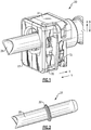
- Figure 1 illustrates a quick connect assembly 20.
- the quick connect assembly 20 includes a housing 22, a retainer/verifier 24, and an endform 26.
- the retainer/verifier 24 retains the endform 26 in the housing 22.
- the direction forward is defined as the direction X
- the direction rearward is defined as the direction Y.
- the direction upward is defined as the direction A
- the direction downward is defined as the direction B.
- the endform 26 includes a tubular body 28 and an annular bead 30 that circumferentially surrounds from the tubular body 28.
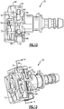
- FIGS 3 , 4 and 5 illustrate the housing 22.
- the housing 22 includes a stem 58 that is receivable in a plastic tube or a rubber hose (not shown).
- the housing 22 includes a passage 32 that receives the endform 26.
- the housing 22 includes a first portion 34 having a first opening 36 and a second portion 38 having a second opening 42 aligned with the first opening 36 and the passage 32.
- the first portion 34 is positioned axially in front of the second portion 38 and attached to the second portion 38 by flanges 46.
- a space 44 is defined between the first portion 34 and the second portion 38.
- Flanges 50 extend behind the second portion 38 and are attached to a third portion 56 to define a space 48 on each side of the passage 32 between the second portion 38 and the third portion 56.
- An outer surface of each flange 50 includes a slot 52 that extends downwardly to a lower surface 54.
- a stop 60 is located on a front surface of the second portion 38 in the space 44 and includes a projection 69 on each upper corner of the stop 60.
- a substantially triangular detent 62 is located on a back side of the second portion 38 on each side of passage 32 near a bottom of the housing 22.
- Each detent 62 includes a locking surface 66 that is substantially perpendicular to the second portion 38 and a ramped surface 64 that extends upwardly to the second portion 38. The locking surface 66 is located below the ramped surface 64.
- the retainer/verifier 24 is a single, integral, unitary, monolithic component.
- the retainer/verifier 24 includes an upper flange 68, two retainer arms 70 extending downwardly from the upper flange 68, and two guiding legs 72 extending downwardly from the upper flange 68.
- the two retainer arms 70 are located in front of and inwardly of the guiding legs 72.
- the two retainer arms 70 each include a chamfered surface 75 on a front inner surface of each retainer arm 70 that can be engaged by the bead 30 of the endform 26 when inserted into the passage 32 of the housing 22.
- a back surface of each of the two retainer arms 70 include a hooked projection 74 each having a recess 71 located at a bottom.
- An upset encountering tab 76 is located above each hooked projection 74.
- a beam 78 having a curved lower surface 80 extends downwardly from the upper flange 68 in between of the two retainer arms 70.
- the two guiding legs 72 each include an outer side surface having a first detent 82, a second detent 84 and a third detent 86.
- the first detent 82 is located near the upper flange 68
- the third detent 86 is located near an end of each leg 72
- the second detent 84 is located between the first detent 82 and the third detent 86.
- a front surface of each guiding leg 72 includes a substantially triangular detent 98 near a bottom of each guiding leg 72.
- the detent 98 includes a ramped surface 100 and a locking surface 102 that is substantially perpendicular to the guiding leg 72.
- the locking surface 102 is located above the ramped surface 100, and the ramped surface extends downwardly towards an end of each guiding leg 72.
- Figures 10 and 11 show the quick connect assembly 20 in a service position.
- the retainer arms 70 are located in the spaces 44, and the guiding legs 72 are located in the spaces 48.
- the retainer/verifier 24 is positioned relative to the housing 22 such that the flanges 50 are located between the second detent 84 and the third detent 86.
- Figures 12 to 15 show the quick connect assembly 20 in a shipping position.
- the retainer/verifier 24 is pushed downwardly relative to the housing 22 such that the flanges 50 are located between the first detent 82 and the second detent 84.
- Both the projections 69 of the stop 60 on the front side of the second portion 38 of the housing 22 engage in the recesses 71 in the hooked projections 74 of the retainer arms 70 (portions of the retainer arms 70 are not shown in Figures 14 ), preventing the retainer/verifier 24 from moving into an engaged position shown in Figures 1 and 16 to 18.
- the endform 26 is inserted into the passage 32, and the bead 30 engages the chamfered surface 75 of the retainer arms 70 of the retainer/verifier 24, causing the retainer arms 70 to bias outwardly.
- the retainer arms 70 bias outwardly, causing the projections 69 of the stops 60 to disengage from the recesses 71 of the hooked projections 74 (shown in Figure 15 ). This then allows the retainer/verifier 24 to move downwardly to the engaged position shown in Figures 1 and 16 to 18 .
- the guiding legs 72 When the retainer/verifier 24 is moved to the engaged position, the guiding legs 72 are moved downwardly such that the first detent 82 is received in the slot 52 of the flange 50 and above the lower surface 54.
- the ramped surface 100 of the detent 98 of each guiding leg 72 travels along the ramped surface 64 of the detents 62 of the housing 22.
- the locking surface 102 of the detent 98 of the retainer/verifier 24 then engages the locking surface 66 of the detent 62 of the housing 22 to prevent the removal of the retainer/verifier 24 from the housing 22 in an upwardly direction.
- the retainer arms 70 bias inwardly to their original position, securing the endform 26 in the housing 22.
- the curved lower surface 80 of the beam 78 of the retainer/verifier 24 is positioned axially in front of the bead 30 of the endform 26.
- the beam 78 provides a redundant latch with a single push lock to prevent removal of the endform 26 from the housing 22 of the quick connect assembly 20.
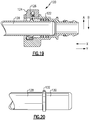
- Figure 19 illustrates another quick connect assembly 120 in a shipping position.
- the quick connect assembly 120 includes a housing 122, a retainer 124, a verifier 126, and an endform 128.
- the retainer 124 secures the endform 128 in the housing 122.
- the directions rearward is defined the direction X, and the direction forward is defined as the direction Y.
- the direction upward is defined as the direction A, and the direction downward is defined as the direction B.
- the endform 128 includes a tubular body 130 and an annular bead 132.
- FIGS 21 to 25 illustrate the housing 122.
- the housing 122 includes a passage 134 that receives the endform 128.
- the housing 122 includes a first portion 136 having a first opening 138 that is attached to a second portion 140 having a second opening 142.
- the openings 138 and 142 are aligned with the passage 134 to receive the endform 128.
- the first portion 136 is spaced axially in front of the second portion 140, and a space 144 is defined therebetween.
- the first portion 136 and the second portion 140 are connected by flanges 146.
- the housing 122 also includes a third portion 152 that is connected to the second portion 140 by flanges 150 to define a space 148 on each side of the passage 134.
- Each of the flanges 150 includes a slot 154 that extends to a lower ledge 157.
- the housing 122 also includes a stem 155 that is receivable in a plastic tube or a rubber hose (not shown).
- a substantially triangular detent 160 is located on each side of passage 134 on a back side of the second portion 140.
- Each detent 160 includes a locking surface 164 that is substantially perpendicular to the second portion 140 and a ramped surface 162 that extends upwardly from the locking surface 164 to the second portion 140.
- the locking surface 164 is located proximate to a bottom of the housing 122.
- FIGS 26 to 29 illustrate the retainer 124.
- the retainer 124 is a single, integral, monolithic unitary component made of a single component.
- the retainer 124 includes an upper flange 166, two retainer arms 168 extending downwardly from the upper flange 166, and two guiding legs 170 extending downwardly from the upper flange 166.
- the two retainer arms 168 are located inwardly of the two guiding legs 170.
- the two retainer arms 168 each include a chamfered surface 172 on a front inner surface of each retainer arm 168 that can be engaged by the bead 132 of the endform 128 when inserted into the housing 122.
- a beam 174 having a curved lower surface 176 extends downwardly from the upper flange 166.
- Tabs 180 on a front surface of each retainer arm 168 of the retainer 124 prevent the endform 128 from pulling out when inserted.
- a back surface of each of the two retainer arms 168 includes a stop 167 near the curved lower surface 176.
- the two guiding legs 170 each include an outer surface having a first detent 182, a second detent 184 and a third detent 186.
- the first detent 182 is located near the upper flange 166
- the third detent 186 is located near an end of each guiding leg 170
- the second detent 184 is located between the first detent 182 and the third detent 186.
- a front surface of each guiding leg 170 includes a substantially triangular detent 188 near the bottom of the guiding leg 170.
- the detent 188 includes a ramped surface 190 and a locking surface 192 perpendicular to the guiding leg 170.
- the locking surface 192 is located closer to the upper flange 166, and the ramped surface 190 extends downwardly towards the end of the guiding leg 170.
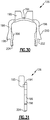
- FIG 30 and 31 illustrates the verifier 126.
- the verifier 126 includes a bridge 194 and two arms 196 that extend downwardly.
- Each arm 196 includes a substantially triangular stop 198 having a first angled surface 200 and a second angled surface 202.
- An end surface 204 is located at the end of each arm 196.
- An inner surface of each arm 196 includes an inwardly facing tab 206.
- Two flanges 195 extend upwardly from the bridge 134 and center the verifier 126 in the housing 122.
- Figure 32 and 33 illustrate the quick connect assembly 120 in the shipping position.
- the verifier 126 is positioned in the housing 122 such that the end portions 204 each touches the stop 176 of the retainer 124. This contact prevents the retainer 124 from moving upwardly or downwardly.
- Figures 34 to 35 also illustrate the quick connect assembly 120 in the shipping position.
- the bead 132 engages the chamfered surface 172 of the two retainer arms 168 of the retainer 124, causing the retainer arms 168 to bias outwardly.
- the arms 196 bias outwardly, releasing the end portion 204 of the verifier 126 from the stops 167 of the retainer 124.
- a force can then be applied downwardly to the retainer 124 to move to the engaged position.
- the locking surface 192 of the detent 188 of the retainer 124 engages the locking surface 164 of the detent 160 of the housing 122 to prevent the removal of the retainer 124 in an upward direction.
- the curved lower surface 176 of the beam 174 of the retainer 124 is positioned axially in front of the bead 132 when the retainer 124 is in the engaged position to provide for a redundant latch with a single push lock.
Landscapes
- Engineering & Computer Science (AREA)
- General Engineering & Computer Science (AREA)
- Mechanical Engineering (AREA)
- Quick-Acting Or Multi-Walled Pipe Joints (AREA)
Description
- This application claims priority to United States Provisional Application No.
61/972,369 filed March 30, 2014 61/910,555 filed December 2, 2013 - A quick connect assembly is employed to releasably retain an endform in a housing with a retainer. Quick connect assemblies can be used in fluid systems. Prior quick connect assemblies include a separate latch and a separate verifier to verify that the endform is properly secured by the latch.
- The document
WO 2009/119058 A shows a fluid quick connector assembly according to the preamble of claim 1. - A fluid quick connector assembly according to an exemplary embodiment of this disclosure, among other possible things includes a housing having a passage configured to receive an end form, and a retainer including a bridge. A single beam extends from the bridge. Two retainer arms extend from the bridge to retain the male endform in the passage of the housing when the retainer is in an engaged position. Two guiding legs extend from the bridge that guide the retainer during movement to the engaged position. The bridge, the beam, the two retainer arms, and the two guiding legs are an integral unitary single piece component, and the beam contacts the endform when the retainer is in the engaged position. An outer surface of each of the two guiding legs includes an upper detent, a lower detent and a middle detent located therebetween.
- In a further embodiment of the foregoing fluid quick connector assembly, the endform includes a tubular body having an annular bead, and the beam is positioned axially forward of the annular bead when the retainer is in the engaged position to provide a redundant latch.
- In a further embodiment of any of the foregoing fluid quick connector assemblies, the beam has a curved lower surface.
- In a further embodiment of any of the foregoing fluid quick connector assemblies, the housing includes a first portion, a second portion, and a third portion. The first portion and the second portion are connected by first flanges with a first space defined therebetween. The second portion and the third portion are connected by second flanges with a second space defined therebetween. The two retainer arms are received in the first space, and the two guiding legs are received in second space.
- In a further embodiment of any of the foregoing fluid quick connector assemblies, the second portion of the housing includes a stop and the two retainer arms each include a hooked projection that engages the stop of the housing to prevent the retainer from moving to the engaged position.
- In a further embodiment of any of the foregoing fluid quick connector assemblies, the two retainer arms of the retainer each include an upset encountering tab, and an annular bead of the endform engages the upset encountering tabs to bias the two retainer arms outwardly to remove the hooked projections from the stop to allow the retainer to move to the engaged position.
- In a further embodiment of any of the foregoing fluid quick connector assemblies, when the retainer is in the engaged position, the two retainer arms bias inwardly to secure the endform in the housing.
- In a further embodiment of any of the foregoing fluid quick connector assemblies, the second portion of the housing includes a first detent and the two retainer arms of the retainer includes a second detent. The first detent and the second detent engage to prevent removal of the retainer from the housing when the retainer is in the engaged position.
- In a further embodiment of any of the foregoing fluid quick connector assemblies, when the retainer is in a service position, the first flanges are located between the middle detent and the lower detent, when the retainer is in a shipping position, the first flanges are located between the middle detent and the upper detent, and when the retainer is in the engaged position, the upper detent is received in the slot of the first flange.
- In a further embodiment of any of the foregoing fluid quick connector assemblies, each of the two retainer arms includes a chamfered inner surface that is engaged by the annular bead of the endform.
- A fluid quick connector assembly according to an exemplary embodiment of this disclosure, among other possible things includes an endform including a tubular body having an annular bead. A housing has a passage configured to receive the endform. The housing includes a first portion, a second portion, and a third portion. The first portion and the second portion are connected by first flanges with a first space defined therebetween. The second portion and the third portion are connected by second flanges with a second space defined therebetween. A retainer includes a bridge. A beam extends from the bridge. The beam has a curved lower surface. The retainer includes two retainer arms extending from the bridge to retain the male endform in the passage of the housing when the retainer is in an engaged position. Two guiding legs extend from the bridge that guide the retainer during movement to the engaged position. The bridge, the beam, the two retainer arms, and the two guiding legs are an integral unitary single piece component. The beam contacts the endform when the retainer is in the engaged position. The beam is positioned axially forward of the annular bead when the retainer is in the engaged position to provide a redundant latch. The two retainer arms are received in the first space of the housing, and the two guiding legs are received in second space of the housing.
- In a further embodiment of the foregoing fluid quick connector assembly, the second portion of the housing includes a stop and the two retainer arms each include a hooked projection that engages the stop of the housing to prevent the retainer from moving to the engaged position.
- In a further embodiment of any of the foregoing fluid quick connector assemblies, the two retainer arms of the retainer each include an upset encountering tab, and an annular bead of the endform engages the upset encountering tabs to bias the two retainer arms outwardly to remove the hooked projections from the stop to allow the retainer to move to the engaged position.
- In a further embodiment of any of the foregoing fluid quick connector assemblies, when the retainer is in the engaged position, the two retainer arms bias inwardly to secure the endform in the housing.
- In a further embodiment of any of the foregoing fluid quick connector assemblies, the second portion of the housing includes a first detent and the two retainer arms of the retainer includes a second detent, and the first detent and the second detent engage to prevent removal of the retainer from the housing when the retainer is in the engaged position.
- In a further embodiment of any of the foregoing fluid quick connector assemblies, when the retainer is in a service position, the first flanges are located between the middle detent and the lower detent, when the retainer is in a shipping position, the first flanges are located between the middle detent and the upper detent, and when the retainer is in the engaged position, the upper detent is received in the slot of the first flange.
- In a further embodiment of any of the foregoing fluid quick connector assemblies, each of the two retainer arms includes a chamfered inner surface that is engaged by the annular bead of the endform.
-
-
Figure 1 illustrates a perspective view of a quick connect assembly in an engaged position; -
Figure 2 illustrates a perspective view of an end form; -
Figure 3 illustrates a perspective view of a housing; -
Figure 4 illustrates a side view of the housing; -
Figure 5 illustrates a top view of the housing; -
Figure 6 illustrates a front view of a retainer/verifier; -
Figure 7 illustrates a rear view of the retainer/verifier; -
Figure 8 illustrates a side view of the retainer/verifier; -
Figure 9 illustrates a perspective view of the retainer/verifier; -
Figure 10 illustrates a side view of the quick connect assembly in a service position; -
Figure 11 illustrates a perspective view of the quick connect assembly in the service position; -
Figure 12 illustrates a side view of the quick connect assembly in a shipping position; -
Figure 13 illustrates a perspective view of the quick connect assembly in the shipping position; -
Figure 14 illustrate a cross-sectional perspective view of the quick connect assembly in the shipping position taken along line 14-14 ofFigure 13 with the endform shown in phantom; -
Figure 15 illustrates a cross-sectional perspective view of the quick connect assembly in the shipping position when a bead of the endform engages and biases outwardly the retainer arms of the retainer/verifier; -
Figure 16 illustrates a side view of the quick connect assembly in the engaged position; -
Figure 17 illustrates a cross-sectional perspective view of the quick connect assembly in the engaged position taken along line 17-17 ofFigure 16 ; -
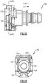
Figure 18 illustrates a front view of the quick connect assembly in the engaged position; -
Figure 19 illustrates a cross-sectional side view of a second quick connect assembly in a shipping position; -
Figure 20 illustrates a side view of an end form; -
Figure 21 illustrates a perspective view of a housing of the second quick connect assembly; -
Figure 22 illustrates a side view of the housing; -
Figure 23 illustrates a top view of the housing; -
Figure 24 illustrates a front view of the housing; -
Figure 25 illustrates a cross-sectional front view of the housing taken along line 25-25 ofFigure 22 ; -
Figure 26 illustrates a front view of a retainer of the second quick connect assembly; -
Figure 27 illustrates a rear view of the retainer; -
Figure 28 illustrates a side view of the retainer; -
Figure 29 illustrates a perspective view of the retainer; -
Figure 30 illustrates a front view of a verifier of the second quick connect assembly; -
Figure 31 illustrates a side view of the verifier; -
Figure 32 illustrates a side view of the second quick connect assembly in a shipping position; -
Figure 33 illustrates a cross-sectional front view of the second quick connect assembly in the shipping position taken along line 33-33 ofFigure 32 ; -
Figure 34 illustrates a side view of the second quick connect assembly in the shipping position; -
Figure 35 illustrates a cross-sectional front view of the second quick connect assembly in the shipping position taken along line 35-35 ofFigure 34 . -
Figure 36 illustrates a side view of the second quick connect assembly in an engaged position; and -
Figure 37 illustrates a cross-sectional front view of the second quick connect assembly in the engaged position taken along line 37-37 ofFigure 36 . -
Figure 1 illustrates aquick connect assembly 20. Thequick connect assembly 20 includes ahousing 22, a retainer/verifier 24, and anendform 26. The retainer/verifier 24 retains theendform 26 in thehousing 22. The direction forward is defined as the direction X, and the direction rearward is defined as the direction Y. The direction upward is defined as the direction A, and the direction downward is defined as the direction B. - As shown in
Figure 2 , theendform 26 includes atubular body 28 and anannular bead 30 that circumferentially surrounds from thetubular body 28. -
Figures 3 ,4 and 5 illustrate thehousing 22. Thehousing 22 includes astem 58 that is receivable in a plastic tube or a rubber hose (not shown). Thehousing 22 includes apassage 32 that receives theendform 26. Thehousing 22 includes afirst portion 34 having afirst opening 36 and asecond portion 38 having asecond opening 42 aligned with thefirst opening 36 and thepassage 32. Thefirst portion 34 is positioned axially in front of thesecond portion 38 and attached to thesecond portion 38 byflanges 46. Aspace 44 is defined between thefirst portion 34 and thesecond portion 38.Flanges 50 extend behind thesecond portion 38 and are attached to athird portion 56 to define aspace 48 on each side of thepassage 32 between thesecond portion 38 and thethird portion 56. An outer surface of eachflange 50 includes aslot 52 that extends downwardly to alower surface 54. - A
stop 60 is located on a front surface of thesecond portion 38 in thespace 44 and includes aprojection 69 on each upper corner of thestop 60. A substantiallytriangular detent 62 is located on a back side of thesecond portion 38 on each side ofpassage 32 near a bottom of thehousing 22. Eachdetent 62 includes a lockingsurface 66 that is substantially perpendicular to thesecond portion 38 and a rampedsurface 64 that extends upwardly to thesecond portion 38. The lockingsurface 66 is located below the rampedsurface 64. - The retainer/
verifier 24 is a single, integral, unitary, monolithic component. The retainer/verifier 24 includes anupper flange 68, tworetainer arms 70 extending downwardly from theupper flange 68, and two guidinglegs 72 extending downwardly from theupper flange 68. The tworetainer arms 70 are located in front of and inwardly of the guidinglegs 72. - The two
retainer arms 70 each include a chamferedsurface 75 on a front inner surface of eachretainer arm 70 that can be engaged by thebead 30 of theendform 26 when inserted into thepassage 32 of thehousing 22. A back surface of each of the tworetainer arms 70 include a hookedprojection 74 each having arecess 71 located at a bottom. An upset encounteringtab 76 is located above each hookedprojection 74. Abeam 78 having a curvedlower surface 80 extends downwardly from theupper flange 68 in between of the tworetainer arms 70. - The two guiding
legs 72 each include an outer side surface having afirst detent 82, asecond detent 84 and athird detent 86. Thefirst detent 82 is located near theupper flange 68, thethird detent 86 is located near an end of eachleg 72, and thesecond detent 84 is located between thefirst detent 82 and thethird detent 86. - A front surface of each guiding
leg 72 includes a substantiallytriangular detent 98 near a bottom of each guidingleg 72. Thedetent 98 includes a rampedsurface 100 and alocking surface 102 that is substantially perpendicular to the guidingleg 72. The lockingsurface 102 is located above the rampedsurface 100, and the ramped surface extends downwardly towards an end of each guidingleg 72. -
Figures 10 and 11 show thequick connect assembly 20 in a service position. Theretainer arms 70 are located in thespaces 44, and the guidinglegs 72 are located in thespaces 48. The retainer/verifier 24 is positioned relative to thehousing 22 such that theflanges 50 are located between thesecond detent 84 and thethird detent 86. -
Figures 12 to 15 show thequick connect assembly 20 in a shipping position. The retainer/verifier 24 is pushed downwardly relative to thehousing 22 such that theflanges 50 are located between thefirst detent 82 and thesecond detent 84. Both theprojections 69 of thestop 60 on the front side of thesecond portion 38 of thehousing 22 engage in therecesses 71 in the hookedprojections 74 of the retainer arms 70 (portions of theretainer arms 70 are not shown inFigures 14 ), preventing the retainer/verifier 24 from moving into an engaged position shown inFigures 1 and16 to 18. - The
endform 26 is inserted into thepassage 32, and thebead 30 engages the chamferedsurface 75 of theretainer arms 70 of the retainer/verifier 24, causing theretainer arms 70 to bias outwardly. When thebead 30 engages the upset encounteringtab 76, theretainer arms 70 bias outwardly, causing theprojections 69 of thestops 60 to disengage from therecesses 71 of the hooked projections 74 (shown inFigure 15 ). This then allows the retainer/verifier 24 to move downwardly to the engaged position shown inFigures 1 and16 to 18 . - When the retainer/
verifier 24 is moved to the engaged position, the guidinglegs 72 are moved downwardly such that thefirst detent 82 is received in theslot 52 of theflange 50 and above thelower surface 54. The rampedsurface 100 of thedetent 98 of each guidingleg 72 travels along the rampedsurface 64 of thedetents 62 of thehousing 22. The lockingsurface 102 of thedetent 98 of the retainer/verifier 24 then engages the lockingsurface 66 of thedetent 62 of thehousing 22 to prevent the removal of the retainer/verifier 24 from thehousing 22 in an upwardly direction. Once thebead 30 passes through theretainer arms 70 of thehousing 22, theretainer arms 70 bias inwardly to their original position, securing theendform 26 in thehousing 22. - As shown in
Figure 18 , when thequick connect assembly 20 is in the engaged position, the curvedlower surface 80 of thebeam 78 of the retainer/verifier 24 is positioned axially in front of thebead 30 of theendform 26. Thebeam 78 provides a redundant latch with a single push lock to prevent removal of the endform 26 from thehousing 22 of thequick connect assembly 20. -
Figure 19 illustrates anotherquick connect assembly 120 in a shipping position. Thequick connect assembly 120 includes ahousing 122, aretainer 124, averifier 126, and anendform 128. Theretainer 124 secures theendform 128 in thehousing 122. The directions rearward is defined the direction X, and the direction forward is defined as the direction Y. The direction upward is defined as the direction A, and the direction downward is defined as the direction B. As shown inFigure 20 , theendform 128 includes atubular body 130 and anannular bead 132. -
Figures 21 to 25 illustrate thehousing 122. Thehousing 122 includes apassage 134 that receives theendform 128. Thehousing 122 includes afirst portion 136 having afirst opening 138 that is attached to asecond portion 140 having asecond opening 142. Theopenings passage 134 to receive theendform 128. Thefirst portion 136 is spaced axially in front of thesecond portion 140, and aspace 144 is defined therebetween. - The
first portion 136 and thesecond portion 140 are connected byflanges 146. Thehousing 122 also includes athird portion 152 that is connected to thesecond portion 140 byflanges 150 to define aspace 148 on each side of thepassage 134. Each of theflanges 150 includes aslot 154 that extends to alower ledge 157. - The
housing 122 also includes astem 155 that is receivable in a plastic tube or a rubber hose (not shown). A substantiallytriangular detent 160 is located on each side ofpassage 134 on a back side of thesecond portion 140. Eachdetent 160 includes a lockingsurface 164 that is substantially perpendicular to thesecond portion 140 and a rampedsurface 162 that extends upwardly from the lockingsurface 164 to thesecond portion 140. The lockingsurface 164 is located proximate to a bottom of thehousing 122. -
Figures 26 to 29 illustrate theretainer 124. Theretainer 124 is a single, integral, monolithic unitary component made of a single component. Theretainer 124 includes anupper flange 166, tworetainer arms 168 extending downwardly from theupper flange 166, and two guidinglegs 170 extending downwardly from theupper flange 166. The tworetainer arms 168 are located inwardly of the two guidinglegs 170. - The two
retainer arms 168 each include achamfered surface 172 on a front inner surface of eachretainer arm 168 that can be engaged by thebead 132 of theendform 128 when inserted into thehousing 122. Abeam 174 having a curvedlower surface 176 extends downwardly from theupper flange 166.Tabs 180 on a front surface of eachretainer arm 168 of theretainer 124 prevent theendform 128 from pulling out when inserted. A back surface of each of the tworetainer arms 168 includes astop 167 near the curvedlower surface 176. - The two guiding
legs 170 each include an outer surface having afirst detent 182, asecond detent 184 and athird detent 186. Thefirst detent 182 is located near theupper flange 166, thethird detent 186 is located near an end of each guidingleg 170, and thesecond detent 184 is located between thefirst detent 182 and thethird detent 186. - A front surface of each guiding
leg 170 includes a substantiallytriangular detent 188 near the bottom of the guidingleg 170. Thedetent 188 includes a rampedsurface 190 and alocking surface 192 perpendicular to the guidingleg 170. The lockingsurface 192 is located closer to theupper flange 166, and the rampedsurface 190 extends downwardly towards the end of the guidingleg 170. -
Figure 30 and 31 illustrates theverifier 126. Theverifier 126 includes abridge 194 and twoarms 196 that extend downwardly. Eacharm 196 includes a substantiallytriangular stop 198 having a firstangled surface 200 and a secondangled surface 202. Anend surface 204 is located at the end of eacharm 196. An inner surface of eacharm 196 includes an inwardly facingtab 206. Twoflanges 195 extend upwardly from thebridge 134 and center theverifier 126 in thehousing 122. - Returning to
Figure 19 , in the shipping position, theretainer 124 cannot be pushed downwardly in the direction B until theendform 128 has been fully inserted into thehousing 122. If theendform 128 is fully inserted, but theretainer 124 is not pushed downwardly, thequick connect assembly 120 will still function until service is performed. -
Figure 32 and 33 illustrate thequick connect assembly 120 in the shipping position. Theverifier 126 is positioned in thehousing 122 such that theend portions 204 each touches thestop 176 of theretainer 124. This contact prevents theretainer 124 from moving upwardly or downwardly. -
Figures 34 to 35 also illustrate thequick connect assembly 120 in the shipping position. When theendform 128 is inserted in to thepassage 134, thebead 132 engages the chamferedsurface 172 of the tworetainer arms 168 of theretainer 124, causing theretainer arms 168 to bias outwardly. When thebead 132 of theendform 128 engages the inwardly facingtab 206 of theverifier 126, thearms 196 bias outwardly, releasing theend portion 204 of theverifier 126 from thestops 167 of theretainer 124. - As shown in
Figures 36 and 37 , a force can then be applied downwardly to theretainer 124 to move to the engaged position. The lockingsurface 192 of thedetent 188 of theretainer 124 engages the lockingsurface 164 of thedetent 160 of thehousing 122 to prevent the removal of theretainer 124 in an upward direction. Additionally, the curvedlower surface 176 of thebeam 174 of theretainer 124 is positioned axially in front of thebead 132 when theretainer 124 is in the engaged position to provide for a redundant latch with a single push lock. - The foregoing description is only exemplary of the principles of the invention. It is, therefore, to be understood that within the scope of the appended claims, the invention may be practiced otherwise than using the example embodiments which have been specifically described. For that reason the following claims should be studied to determine the true scope and content of this invention.
Claims (15)
- A fluid quick connector assembly comprising:a housing (22) having a passage (32) configured to receive an endform (26); anda retainer (24) including a bridge, a single beam (78) extending from the bridge, two retainer arms (70) extending from the bridge (68) to retain the male endform (26) in the passage (32) of the housing (22) when the retainer (24) is in an engaged position, and two guiding legs (72) extending from the bridge (68) that guide the retainer (24) during movement to the engaged position, wherein the bridge (68), the beam (78), the two retainer arms (70), and the two guiding legs (72) are an integral unitary single piece component, the beam (78) is adapted to contact the endform (26) when the retainer (24) is in the engaged position, characterized in that an outer surface of each of the two guiding legs (72) includes an upper detent (82), a lower detent (86) and a middle detent (84) located therebetween.
- The fluid quick connector assembly as recited in claim 1 including the endform (26), wherein the endform (26) includes a tubular body (28) having an annular bead (30), and the beam (78) is positioned axially forward of the annular bead (30) when the retainer (24) is in the engaged position to provide a redundant latch.
- The fluid quick connector assembly as recited in claim 1 wherein the beam (78) has a curved lower surface (80).
- The fluid quick connector assembly as recited in claim 1 wherein the housing (22) includes a first portion (34), a second portion (38), and a third portion (56), wherein the first portion (34) and the second portion (38) are connected by first flanges (46) with a first space (44) defined therebetween, the second portion (38) and the third portion (56) are connected by second flanges (50) with a second space (48) defined therebetween, the two retainer arms (70) are received in the first space (44), and the two guiding legs (72) are received in the second space (48).
- The fluid quick connector assembly as recited in claim 4 wherein the second portion (38) of the housing (22) includes a stop (60) and the two retainer arms (70) each include a hooked projection (74) that engages the stop (60) of the housing (22) to prevent the retainer (24) from moving to the engaged position.
- The fluid quick connector assembly as recited in claim 5 including the endform (26), wherein the two retainer arms (70) of the retainer each include an upset encountering tab (76), and an annular bead (30) of the endform (26) engages the upset encountering tabs (76) to bias the two retainer arms (70) outwardly to remove the hooked projections (74) from the stop (60) to allow the retainer (24) to move to the engaged position.
- The fluid quick connector assembly as recited in claim 6 wherein, when the retainer (24) is in the engaged position, the two retainer arms (70) bias inwardly to secure the endform (26) in the housing (22).
- The fluid quick connector assembly as recited in claim 4 wherein the second portion (38) of the housing (22) includes a first detent (62) and the two retainer arms (70) of the retainer (24) includes a second detent (98), and the first detent (62) and the second detent (98) engage to prevent removal of the retainer (24) from the housing (22) when the retainer (24) is in the engaged position.
- The fluid quick connector assembly as recited in claim 1, further comprising:an endform (26) including a tubular body (28) having an annular bead (30);wherein the housing (22) includes a first portion (34), a second portion (38), and a third portion (56), the first portion (34) and the second portion (38) are connected by first flanges (46) with a first space (44) defined therebetween, the second portion (38) and the third portion (56) are connected by second flanges (50) with a second space (48) defined therebetween; andwherein the beam (78) has a curved lower surface (80), and is positioned axially forward of the annular bead (30) when the retainer (24) is in the engaged position to provide a redundant latch, wherein the two retainer arms (70) are received in the first space (44) of the housing (22), and the two guiding legs (72) are received in the second space (48) of the housing (22).
- The fluid quick connector assembly as recited in claim 9 wherein the second portion (38) of the housing (22) includes a stop (60) and the two retainer arms (70) each include a hooked projection (74) that engages the stop (60) of the housing (22) to prevent the retainer (24) from moving to the engaged position.
- The fluid quick connector assembly as recited in claim 10 wherein the two retainer arms (70) of the retainer (24) each include an upset encountering tab (76), and an annular bead (30) of the endform (26) engages the upset encountering tabs (76) to bias the two retainer arms (70) outwardly to remove the hooked projections (74) from the stop (60) to allow the retainer (24) to move to the engaged position.
- The fluid quick connector assembly as recited in claim 11 wherein, when the retainer (24) is in the engaged position, the two retainer arms (70) bias inwardly to secure the endform (26) in the housing (22).
- The fluid quick connector assembly as recited in claim 9 wherein the second portion of the housing (22) includes a first detent (62) and the two retainer arms (70) of the retainer (24) include a second detent (98), and the first detent (62) and the second detent (98) engage to prevent removal of the retainer (24) from the housing (22) when the retainer (24) is in the engaged position.
- The fluid quick connector assembly as recited in claim 1 or 9 wherein, when the retainer (24) is in a service position, the second flanges (50) are located between the middle detent (84) and the lower detent (86), when the retainer (24) is in a shipping position, the second flanges (50) are located between the middle detent (84) and the upper detent (82), and when the retainer (24) is in the engaged position, the upper detent (82) is received in the slot (52) of the second flange (50).
- The fluid quick connector assembly as recited in claim 1 or 9 wherein each of the two retainer arms (70) includes a chamfered inner surface (75) that is adapted to be engaged by the annular bead (30) of the endform (26).
Applications Claiming Priority (3)
| Application Number | Priority Date | Filing Date | Title |
|---|---|---|---|
| US201361910555P | 2013-12-02 | 2013-12-02 | |
| US201461972369P | 2014-03-30 | 2014-03-30 | |
| PCT/US2014/068044 WO2015084782A1 (en) | 2013-12-02 | 2014-12-02 | Quick connect assembly |
Publications (2)
| Publication Number | Publication Date |
|---|---|
| EP3077718A1 EP3077718A1 (en) | 2016-10-12 |
| EP3077718B1 true EP3077718B1 (en) | 2019-06-19 |
Family
ID=52130852
Family Applications (1)
| Application Number | Title | Priority Date | Filing Date |
|---|---|---|---|
| EP14815543.5A Active EP3077718B1 (en) | 2013-12-02 | 2014-12-02 | Quick connect assembly |
Country Status (7)
| Country | Link |
|---|---|
| US (1) | US10428987B2 (en) |
| EP (1) | EP3077718B1 (en) |
| JP (1) | JP6507164B2 (en) |
| CN (1) | CN105899865B (en) |
| CA (1) | CA2929371C (en) |
| MX (1) | MX377238B (en) |
| WO (1) | WO2015084782A1 (en) |
Families Citing this family (16)
| Publication number | Priority date | Publication date | Assignee | Title |
|---|---|---|---|---|
| JP2015086964A (en) * | 2013-10-31 | 2015-05-07 | 住友理工株式会社 | Quick connector |
| JP5753284B1 (en) * | 2014-01-16 | 2015-07-22 | 住友理工株式会社 | Quick connector |
| JP6149081B2 (en) * | 2015-09-24 | 2017-06-14 | 住友理工株式会社 | Quick connector |
| DE102016109051A1 (en) * | 2015-10-21 | 2017-04-27 | Voss Automotive Gmbh | Connectors for media cables |
| FR3044070B1 (en) * | 2015-11-20 | 2019-06-28 | A Raymond Et Cie | SAFETY TUBULAR CONNECTION WITH AUTOMATIC CONNECTION |
| US10612707B2 (en) | 2017-11-28 | 2020-04-07 | Cooper-Standard Automotive, Inc. | Quick connect assembly and method |
| TWI679369B (en) * | 2018-01-25 | 2019-12-11 | 效高崗企業有限公司 | Quick joint structure |
| JP6722714B2 (en) * | 2018-04-26 | 2020-07-15 | 住友理工株式会社 | Quick connector |
| DE102018219932A1 (en) * | 2018-11-21 | 2020-05-28 | Fränkische Industrial Pipes GmbH & Co. KG | coupling |
| DE102018220521A1 (en) | 2018-11-28 | 2020-05-28 | Fränkische Industrial Pipes GmbH & Co. KG | Fluid connection |
| DE102019111199A1 (en) * | 2019-04-30 | 2020-11-05 | Voss Automotive Gmbh | Connectors for media lines |
| US11578828B2 (en) * | 2020-12-03 | 2023-02-14 | Cooper-Standard Automotive, Inc. | Connector having a guided pilot |
| US11982382B2 (en) | 2021-02-22 | 2024-05-14 | Cooper-Standard Automotive Inc. | Quick connector with bracket retainer |
| JP7150210B1 (en) * | 2022-07-08 | 2022-10-07 | 三桜工業株式会社 | plumbing fittings |
| CN119522339A (en) * | 2022-07-11 | 2025-02-25 | 株式会社东乡制作所 | Connectors |
| KR102925157B1 (en) * | 2023-12-26 | 2026-02-11 | 부국산업주식회사 | Locksprings for Securing Quick Connectors and Quick Connector Thereof |
Family Cites Families (16)
| Publication number | Priority date | Publication date | Assignee | Title |
|---|---|---|---|---|
| DE19946260C1 (en) | 1999-09-27 | 2001-01-11 | Itt Mfg Enterprises Inc | Quick-fit coupling for hose or pipeline in automobile has nipple inserted in opening in coupling housing and secured via locking element provided with opposing grip surfaces for its release |
| DE10058087B4 (en) * | 2000-11-23 | 2004-06-17 | Eaton Fluid Power Gmbh | Quick connector |
| JP4234467B2 (en) * | 2002-06-04 | 2009-03-04 | 株式会社パイオラックス | Connector with check function |
| JP4236952B2 (en) | 2003-02-18 | 2009-03-11 | 株式会社東郷製作所 | connector |
| JP4041457B2 (en) | 2003-12-12 | 2008-01-30 | 三桜工業株式会社 | Quick connector |
| DE102004062887B3 (en) * | 2004-12-27 | 2005-10-13 | A. Raymond & Cie | Coupling has locking protrusion which in extended position of plug-in component when it is not properly fitted in housing component prevents movement of locking component into inserted position |
| DE102006047267B4 (en) * | 2006-10-04 | 2010-02-04 | A. Raymond Et Cie | Coupling part for a fluid line coupling |
| JP2009257583A (en) * | 2008-03-27 | 2009-11-05 | Toyoda Gosei Co Ltd | Connector |
| US8041033B2 (en) * | 2008-04-10 | 2011-10-18 | Red Hat, Inc. | Cipher feedback with variable block chaining |
| JP5518522B2 (en) | 2010-02-23 | 2014-06-11 | 株式会社ニフコ | connector |
| BR112013002456B8 (en) | 2010-09-30 | 2022-10-18 | Tokai Rubber Ind Ltd | QUICK DISCONNECT CONNECTOR |
| JP5797547B2 (en) * | 2011-12-27 | 2015-10-21 | 株式会社ニフコ | connector |
| JP6067366B2 (en) * | 2012-12-20 | 2017-01-25 | 住友理工株式会社 | Piping connection structure |
| JP2015086964A (en) * | 2013-10-31 | 2015-05-07 | 住友理工株式会社 | Quick connector |
| FR3021386B1 (en) * | 2014-05-22 | 2017-02-24 | A Raymond Et Cie | TUBULAR CONNECTION WITH AUTOMATIC CONNECTION |
| FR3044070B1 (en) * | 2015-11-20 | 2019-06-28 | A Raymond Et Cie | SAFETY TUBULAR CONNECTION WITH AUTOMATIC CONNECTION |
-
2014
- 2014-12-02 CA CA2929371A patent/CA2929371C/en active Active
- 2014-12-02 WO PCT/US2014/068044 patent/WO2015084782A1/en not_active Ceased
- 2014-12-02 CN CN201480065822.6A patent/CN105899865B/en active Active
- 2014-12-02 US US15/037,716 patent/US10428987B2/en active Active
- 2014-12-02 JP JP2016535654A patent/JP6507164B2/en active Active
- 2014-12-02 EP EP14815543.5A patent/EP3077718B1/en active Active
- 2014-12-02 MX MX2016007055A patent/MX377238B/en active IP Right Grant
Non-Patent Citations (1)
| Title |
|---|
| None * |
Also Published As
| Publication number | Publication date |
|---|---|
| US10428987B2 (en) | 2019-10-01 |
| MX377238B (en) | 2025-03-07 |
| CN105899865A (en) | 2016-08-24 |
| US20160298800A1 (en) | 2016-10-13 |
| CA2929371A1 (en) | 2015-06-11 |
| EP3077718A1 (en) | 2016-10-12 |
| CN105899865B (en) | 2018-08-17 |
| CA2929371C (en) | 2020-12-01 |
| MX2016007055A (en) | 2016-12-12 |
| JP6507164B2 (en) | 2019-04-24 |
| WO2015084782A1 (en) | 2015-06-11 |
| JP2017502217A (en) | 2017-01-19 |
Similar Documents
| Publication | Publication Date | Title |
|---|---|---|
| CA2929371C (en) | Quick connect assembly | |
| CN209084244U (en) | Connector assembly | |
| US9016729B2 (en) | Quick connector and checker | |
| EP2567135B1 (en) | Connector assembly | |
| CN107429868B (en) | Quick connector | |
| KR101322876B1 (en) | Connecting element for a fluid connection | |
| CN104024716B (en) | Connector | |
| KR101798309B1 (en) | Plug-in connection for two pipes and method for assembling the plug-in connection | |
| US10323782B2 (en) | Quick connector | |
| CN103518093B (en) | Snap joint | |
| WO2020135553A1 (en) | Quick connector | |
| CN113811714B (en) | Quick connector | |
| US10415734B2 (en) | Pipe coupling | |
| JP2005214416A (en) | Fluid quick connector, top hut of fluid quick connector for preventing wrong insertion and method of preventing wrong insertion | |
| JP6722714B2 (en) | Quick connector | |
| EP3803183B1 (en) | Quick connector | |
| CN113227629A (en) | Coupling device | |
| CN114593297A (en) | quick connector | |
| CN116134259A (en) | Quick Connector Assembly for Fluid Lines with Positive Assurance Feature | |
| JP2018165544A (en) | Connector unit | |
| US20090302600A1 (en) | metal coupling with locked position | |
| JP6284075B2 (en) | connector | |
| HK1189399A (en) | Quick connector |
Legal Events
| Date | Code | Title | Description |
|---|---|---|---|
| PUAI | Public reference made under article 153(3) epc to a published international application that has entered the european phase |
Free format text: ORIGINAL CODE: 0009012 |
|
| 17P | Request for examination filed |
Effective date: 20160426 |
|
| AK | Designated contracting states |
Kind code of ref document: A1 Designated state(s): AL AT BE BG CH CY CZ DE DK EE ES FI FR GB GR HR HU IE IS IT LI LT LU LV MC MK MT NL NO PL PT RO RS SE SI SK SM TR |
|
| AX | Request for extension of the european patent |
Extension state: BA ME |
|
| DAX | Request for extension of the european patent (deleted) | ||
| GRAP | Despatch of communication of intention to grant a patent |
Free format text: ORIGINAL CODE: EPIDOSNIGR1 |
|
| STAA | Information on the status of an ep patent application or granted ep patent |
Free format text: STATUS: GRANT OF PATENT IS INTENDED |
|
| INTG | Intention to grant announced |
Effective date: 20181130 |
|
| GRAS | Grant fee paid |
Free format text: ORIGINAL CODE: EPIDOSNIGR3 |
|
| GRAJ | Information related to disapproval of communication of intention to grant by the applicant or resumption of examination proceedings by the epo deleted |
Free format text: ORIGINAL CODE: EPIDOSDIGR1 |
|
| GRAL | Information related to payment of fee for publishing/printing deleted |
Free format text: ORIGINAL CODE: EPIDOSDIGR3 |
|
| STAA | Information on the status of an ep patent application or granted ep patent |
Free format text: STATUS: REQUEST FOR EXAMINATION WAS MADE |
|
| INTC | Intention to grant announced (deleted) | ||
| GRAR | Information related to intention to grant a patent recorded |
Free format text: ORIGINAL CODE: EPIDOSNIGR71 |
|
| STAA | Information on the status of an ep patent application or granted ep patent |
Free format text: STATUS: GRANT OF PATENT IS INTENDED |
|
| GRAA | (expected) grant |
Free format text: ORIGINAL CODE: 0009210 |
|
| STAA | Information on the status of an ep patent application or granted ep patent |
Free format text: STATUS: THE PATENT HAS BEEN GRANTED |
|
| AK | Designated contracting states |
Kind code of ref document: B1 Designated state(s): AL AT BE BG CH CY CZ DE DK EE ES FI FR GB GR HR HU IE IS IT LI LT LU LV MC MK MT NL NO PL PT RO RS SE SI SK SM TR |
|
| INTG | Intention to grant announced |
Effective date: 20190513 |
|
| REG | Reference to a national code |
Ref country code: GB Ref legal event code: FG4D |
|
| RIN1 | Information on inventor provided before grant (corrected) |
Inventor name: FREDERIKSEN, STEVE Inventor name: GOCHA, KENNETH Inventor name: KLINGER, GARY |
|
| REG | Reference to a national code |
Ref country code: CH Ref legal event code: EP |
|
| REG | Reference to a national code |
Ref country code: IE Ref legal event code: FG4D |
|
| REG | Reference to a national code |
Ref country code: DE Ref legal event code: R096 Ref document number: 602014048762 Country of ref document: DE |
|
| REG | Reference to a national code |
Ref country code: AT Ref legal event code: REF Ref document number: 1145971 Country of ref document: AT Kind code of ref document: T Effective date: 20190715 |
|
| REG | Reference to a national code |
Ref country code: NL Ref legal event code: MP Effective date: 20190619 |
|
| PG25 | Lapsed in a contracting state [announced via postgrant information from national office to epo] |
Ref country code: AL Free format text: LAPSE BECAUSE OF FAILURE TO SUBMIT A TRANSLATION OF THE DESCRIPTION OR TO PAY THE FEE WITHIN THE PRESCRIBED TIME-LIMIT Effective date: 20190619 Ref country code: FI Free format text: LAPSE BECAUSE OF FAILURE TO SUBMIT A TRANSLATION OF THE DESCRIPTION OR TO PAY THE FEE WITHIN THE PRESCRIBED TIME-LIMIT Effective date: 20190619 Ref country code: HR Free format text: LAPSE BECAUSE OF FAILURE TO SUBMIT A TRANSLATION OF THE DESCRIPTION OR TO PAY THE FEE WITHIN THE PRESCRIBED TIME-LIMIT Effective date: 20190619 Ref country code: LT Free format text: LAPSE BECAUSE OF FAILURE TO SUBMIT A TRANSLATION OF THE DESCRIPTION OR TO PAY THE FEE WITHIN THE PRESCRIBED TIME-LIMIT Effective date: 20190619 Ref country code: SE Free format text: LAPSE BECAUSE OF FAILURE TO SUBMIT A TRANSLATION OF THE DESCRIPTION OR TO PAY THE FEE WITHIN THE PRESCRIBED TIME-LIMIT Effective date: 20190619 Ref country code: NO Free format text: LAPSE BECAUSE OF FAILURE TO SUBMIT A TRANSLATION OF THE DESCRIPTION OR TO PAY THE FEE WITHIN THE PRESCRIBED TIME-LIMIT Effective date: 20190919 |
|
| REG | Reference to a national code |
Ref country code: LT Ref legal event code: MG4D |
|
| PG25 | Lapsed in a contracting state [announced via postgrant information from national office to epo] |
Ref country code: LV Free format text: LAPSE BECAUSE OF FAILURE TO SUBMIT A TRANSLATION OF THE DESCRIPTION OR TO PAY THE FEE WITHIN THE PRESCRIBED TIME-LIMIT Effective date: 20190619 Ref country code: GR Free format text: LAPSE BECAUSE OF FAILURE TO SUBMIT A TRANSLATION OF THE DESCRIPTION OR TO PAY THE FEE WITHIN THE PRESCRIBED TIME-LIMIT Effective date: 20190920 Ref country code: BG Free format text: LAPSE BECAUSE OF FAILURE TO SUBMIT A TRANSLATION OF THE DESCRIPTION OR TO PAY THE FEE WITHIN THE PRESCRIBED TIME-LIMIT Effective date: 20190919 Ref country code: RS Free format text: LAPSE BECAUSE OF FAILURE TO SUBMIT A TRANSLATION OF THE DESCRIPTION OR TO PAY THE FEE WITHIN THE PRESCRIBED TIME-LIMIT Effective date: 20190619 |
|
| REG | Reference to a national code |
Ref country code: AT Ref legal event code: MK05 Ref document number: 1145971 Country of ref document: AT Kind code of ref document: T Effective date: 20190619 |
|
| PG25 | Lapsed in a contracting state [announced via postgrant information from national office to epo] |
Ref country code: CZ Free format text: LAPSE BECAUSE OF FAILURE TO SUBMIT A TRANSLATION OF THE DESCRIPTION OR TO PAY THE FEE WITHIN THE PRESCRIBED TIME-LIMIT Effective date: 20190619 Ref country code: AT Free format text: LAPSE BECAUSE OF FAILURE TO SUBMIT A TRANSLATION OF THE DESCRIPTION OR TO PAY THE FEE WITHIN THE PRESCRIBED TIME-LIMIT Effective date: 20190619 Ref country code: NL Free format text: LAPSE BECAUSE OF FAILURE TO SUBMIT A TRANSLATION OF THE DESCRIPTION OR TO PAY THE FEE WITHIN THE PRESCRIBED TIME-LIMIT Effective date: 20190619 Ref country code: RO Free format text: LAPSE BECAUSE OF FAILURE TO SUBMIT A TRANSLATION OF THE DESCRIPTION OR TO PAY THE FEE WITHIN THE PRESCRIBED TIME-LIMIT Effective date: 20190619 Ref country code: PT Free format text: LAPSE BECAUSE OF FAILURE TO SUBMIT A TRANSLATION OF THE DESCRIPTION OR TO PAY THE FEE WITHIN THE PRESCRIBED TIME-LIMIT Effective date: 20191021 Ref country code: EE Free format text: LAPSE BECAUSE OF FAILURE TO SUBMIT A TRANSLATION OF THE DESCRIPTION OR TO PAY THE FEE WITHIN THE PRESCRIBED TIME-LIMIT Effective date: 20190619 Ref country code: SK Free format text: LAPSE BECAUSE OF FAILURE TO SUBMIT A TRANSLATION OF THE DESCRIPTION OR TO PAY THE FEE WITHIN THE PRESCRIBED TIME-LIMIT Effective date: 20190619 |
|
| PG25 | Lapsed in a contracting state [announced via postgrant information from national office to epo] |
Ref country code: IS Free format text: LAPSE BECAUSE OF FAILURE TO SUBMIT A TRANSLATION OF THE DESCRIPTION OR TO PAY THE FEE WITHIN THE PRESCRIBED TIME-LIMIT Effective date: 20191019 Ref country code: SM Free format text: LAPSE BECAUSE OF FAILURE TO SUBMIT A TRANSLATION OF THE DESCRIPTION OR TO PAY THE FEE WITHIN THE PRESCRIBED TIME-LIMIT Effective date: 20190619 Ref country code: IT Free format text: LAPSE BECAUSE OF FAILURE TO SUBMIT A TRANSLATION OF THE DESCRIPTION OR TO PAY THE FEE WITHIN THE PRESCRIBED TIME-LIMIT Effective date: 20190619 Ref country code: ES Free format text: LAPSE BECAUSE OF FAILURE TO SUBMIT A TRANSLATION OF THE DESCRIPTION OR TO PAY THE FEE WITHIN THE PRESCRIBED TIME-LIMIT Effective date: 20190619 |
|
| PG25 | Lapsed in a contracting state [announced via postgrant information from national office to epo] |
Ref country code: TR Free format text: LAPSE BECAUSE OF FAILURE TO SUBMIT A TRANSLATION OF THE DESCRIPTION OR TO PAY THE FEE WITHIN THE PRESCRIBED TIME-LIMIT Effective date: 20190619 |
|
| PG25 | Lapsed in a contracting state [announced via postgrant information from national office to epo] |
Ref country code: DK Free format text: LAPSE BECAUSE OF FAILURE TO SUBMIT A TRANSLATION OF THE DESCRIPTION OR TO PAY THE FEE WITHIN THE PRESCRIBED TIME-LIMIT Effective date: 20190619 Ref country code: PL Free format text: LAPSE BECAUSE OF FAILURE TO SUBMIT A TRANSLATION OF THE DESCRIPTION OR TO PAY THE FEE WITHIN THE PRESCRIBED TIME-LIMIT Effective date: 20190619 |
|
| PG25 | Lapsed in a contracting state [announced via postgrant information from national office to epo] |
Ref country code: IS Free format text: LAPSE BECAUSE OF FAILURE TO SUBMIT A TRANSLATION OF THE DESCRIPTION OR TO PAY THE FEE WITHIN THE PRESCRIBED TIME-LIMIT Effective date: 20200224 |
|
| REG | Reference to a national code |
Ref country code: DE Ref legal event code: R097 Ref document number: 602014048762 Country of ref document: DE |
|
| PLBE | No opposition filed within time limit |
Free format text: ORIGINAL CODE: 0009261 |
|
| STAA | Information on the status of an ep patent application or granted ep patent |
Free format text: STATUS: NO OPPOSITION FILED WITHIN TIME LIMIT |
|
| PG2D | Information on lapse in contracting state deleted |
Ref country code: IS |
|
| REG | Reference to a national code |
Ref country code: CH Ref legal event code: PL |
|
| 26N | No opposition filed |
Effective date: 20200603 |
|
| REG | Reference to a national code |
Ref country code: BE Ref legal event code: MM Effective date: 20191231 |
|
| PG25 | Lapsed in a contracting state [announced via postgrant information from national office to epo] |
Ref country code: SI Free format text: LAPSE BECAUSE OF FAILURE TO SUBMIT A TRANSLATION OF THE DESCRIPTION OR TO PAY THE FEE WITHIN THE PRESCRIBED TIME-LIMIT Effective date: 20190619 Ref country code: MC Free format text: LAPSE BECAUSE OF FAILURE TO SUBMIT A TRANSLATION OF THE DESCRIPTION OR TO PAY THE FEE WITHIN THE PRESCRIBED TIME-LIMIT Effective date: 20190619 |
|
| PG25 | Lapsed in a contracting state [announced via postgrant information from national office to epo] |
Ref country code: IE Free format text: LAPSE BECAUSE OF NON-PAYMENT OF DUE FEES Effective date: 20191202 Ref country code: LU Free format text: LAPSE BECAUSE OF NON-PAYMENT OF DUE FEES Effective date: 20191202 |
|
| PG25 | Lapsed in a contracting state [announced via postgrant information from national office to epo] |
Ref country code: LI Free format text: LAPSE BECAUSE OF NON-PAYMENT OF DUE FEES Effective date: 20191231 Ref country code: BE Free format text: LAPSE BECAUSE OF NON-PAYMENT OF DUE FEES Effective date: 20191231 Ref country code: CH Free format text: LAPSE BECAUSE OF NON-PAYMENT OF DUE FEES Effective date: 20191231 |
|
| PG25 | Lapsed in a contracting state [announced via postgrant information from national office to epo] |
Ref country code: CY Free format text: LAPSE BECAUSE OF FAILURE TO SUBMIT A TRANSLATION OF THE DESCRIPTION OR TO PAY THE FEE WITHIN THE PRESCRIBED TIME-LIMIT Effective date: 20190619 |
|
| PG25 | Lapsed in a contracting state [announced via postgrant information from national office to epo] |
Ref country code: MT Free format text: LAPSE BECAUSE OF FAILURE TO SUBMIT A TRANSLATION OF THE DESCRIPTION OR TO PAY THE FEE WITHIN THE PRESCRIBED TIME-LIMIT Effective date: 20190619 Ref country code: HU Free format text: LAPSE BECAUSE OF FAILURE TO SUBMIT A TRANSLATION OF THE DESCRIPTION OR TO PAY THE FEE WITHIN THE PRESCRIBED TIME-LIMIT; INVALID AB INITIO Effective date: 20141202 |
|
| PGFP | Annual fee paid to national office [announced via postgrant information from national office to epo] |
Ref country code: GB Payment date: 20211227 Year of fee payment: 8 |
|
| PG25 | Lapsed in a contracting state [announced via postgrant information from national office to epo] |
Ref country code: MK Free format text: LAPSE BECAUSE OF FAILURE TO SUBMIT A TRANSLATION OF THE DESCRIPTION OR TO PAY THE FEE WITHIN THE PRESCRIBED TIME-LIMIT Effective date: 20190619 |
|
| P01 | Opt-out of the competence of the unified patent court (upc) registered |
Effective date: 20230529 |
|
| GBPC | Gb: european patent ceased through non-payment of renewal fee |
Effective date: 20221202 |
|
| PG25 | Lapsed in a contracting state [announced via postgrant information from national office to epo] |
Ref country code: GB Free format text: LAPSE BECAUSE OF NON-PAYMENT OF DUE FEES Effective date: 20221202 |
|
| PGFP | Annual fee paid to national office [announced via postgrant information from national office to epo] |
Ref country code: FR Payment date: 20251226 Year of fee payment: 12 |
|
| PGFP | Annual fee paid to national office [announced via postgrant information from national office to epo] |
Ref country code: DE Payment date: 20251229 Year of fee payment: 12 |