EP3077616B1 - Apparatus and method for disconnecting male and female subsea connectors - Google Patents
Apparatus and method for disconnecting male and female subsea connectors Download PDFInfo
- Publication number
- EP3077616B1 EP3077616B1 EP14809690.2A EP14809690A EP3077616B1 EP 3077616 B1 EP3077616 B1 EP 3077616B1 EP 14809690 A EP14809690 A EP 14809690A EP 3077616 B1 EP3077616 B1 EP 3077616B1
- Authority
- EP
- European Patent Office
- Prior art keywords
- male connector
- sleeve
- release tool
- ball
- connector
- Prior art date
- Legal status (The legal status is an assumption and is not a legal conclusion. Google has not performed a legal analysis and makes no representation as to the accuracy of the status listed.)
- Active
Links
Images




Classifications
-
- E—FIXED CONSTRUCTIONS
- E21—EARTH OR ROCK DRILLING; MINING
- E21B—EARTH OR ROCK DRILLING; OBTAINING OIL, GAS, WATER, SOLUBLE OR MELTABLE MATERIALS OR A SLURRY OF MINERALS FROM WELLS
- E21B43/00—Methods or apparatus for obtaining oil, gas, water, soluble or meltable materials or a slurry of minerals from wells
- E21B43/01—Methods or apparatus for obtaining oil, gas, water, soluble or meltable materials or a slurry of minerals from wells specially adapted for obtaining from underwater installations
- E21B43/0107—Connecting of flow lines to offshore structures
-
- E—FIXED CONSTRUCTIONS
- E21—EARTH OR ROCK DRILLING; MINING
- E21B—EARTH OR ROCK DRILLING; OBTAINING OIL, GAS, WATER, SOLUBLE OR MELTABLE MATERIALS OR A SLURRY OF MINERALS FROM WELLS
- E21B17/00—Drilling rods or pipes; Flexible drill strings; Kellies; Drill collars; Sucker rods; Cables; Casings; Tubings
- E21B17/01—Risers
- E21B17/017—Bend restrictors for limiting stress on risers
-
- E—FIXED CONSTRUCTIONS
- E21—EARTH OR ROCK DRILLING; MINING
- E21B—EARTH OR ROCK DRILLING; OBTAINING OIL, GAS, WATER, SOLUBLE OR MELTABLE MATERIALS OR A SLURRY OF MINERALS FROM WELLS
- E21B17/00—Drilling rods or pipes; Flexible drill strings; Kellies; Drill collars; Sucker rods; Cables; Casings; Tubings
- E21B17/02—Couplings; joints
- E21B17/04—Couplings; joints between rod or the like and bit or between rod and rod or the like
- E21B17/046—Couplings; joints between rod or the like and bit or between rod and rod or the like with ribs, pins, or jaws, and complementary grooves or the like, e.g. bayonet catches
- E21B17/0465—Couplings; joints between rod or the like and bit or between rod and rod or the like with ribs, pins, or jaws, and complementary grooves or the like, e.g. bayonet catches characterised by radially inserted locking elements
-
- E—FIXED CONSTRUCTIONS
- E21—EARTH OR ROCK DRILLING; MINING
- E21B—EARTH OR ROCK DRILLING; OBTAINING OIL, GAS, WATER, SOLUBLE OR MELTABLE MATERIALS OR A SLURRY OF MINERALS FROM WELLS
- E21B19/00—Handling rods, casings, tubes or the like outside the borehole, e.g. in the derrick; Apparatus for feeding the rods or cables
- E21B19/002—Handling rods, casings, tubes or the like outside the borehole, e.g. in the derrick; Apparatus for feeding the rods or cables specially adapted for underwater drilling
- E21B19/004—Handling rods, casings, tubes or the like outside the borehole, e.g. in the derrick; Apparatus for feeding the rods or cables specially adapted for underwater drilling supporting a riser from a drilling or production platform
Definitions
- the present invention relates to an apparatus and method for disconnecting male and female connectors such as those used in oil pipeline connections.
- Risers are used in subsea applications to provide a conduit for oil to be extracted from under the sea bed to floating production storage and offloading vessels (FPSO) or similar.
- the risers comprise a number of pipe sections that are joined together so that the oil can be conveyed safely to the surface of deep water. Due to movement of the vessel on the surface of the water, the risers are often subj ected to external forces that cause the risers to flex and kink thereby resulting in damage to the risers.
- bend stiffeners comprising a polyurethane conical shaped moulding are used to limit bending of the risers and protect the riser minimum bend radius.
- Bend stiffeners are typically coupled to a FPSO vessel using a male and female connector. One of the connectors is usually attached to the vessel and the other connector is usually attached to the bend stiffener. The bend stiffener and corresponding connector are coupled to the connector on the vessel to lock the two together and hold the bend stiffener firmly in place. The riser can then be safely attached to the vessel through the bend stiffener so that oil can be extracted from the oil field in question.
- the male and female connectors may typically be urged apart using hydraulic rams, release or riser clamps.
- hydraulic rams, release or riser clamps Such methods of separation can be prone to failure and require physical intervention by divers which is undesirable especially in potentially hazardous conditions.
- WO2005/095198 discloses a connector for releasable connection between an anchorage in the form of a female part arranged on a floating means and a male part formed at the end of a retrievable umbilical provided with a bend stiffener.
- US3948545 discloses a vertical string of pipe such as is used in an offshore piling comprising a plurality of pipe joints connected together by connector means, each connector means comprising a breech block type connection with a latch to hold the connector means in engagement, one of the connector means latches being remotely disengageable by means of a releasing tool lowered down through the string of pipe, the one latch including a bar extending radially through the wall of the connector means to engage the latch, the bar being movable radially outwardly upon being engaged by the releasing tool so as to either break off a portion of the latch or move the latch out of engagement.
- GB2424684 (A ) discloses a pipe connection between an elongate male member and a female member, the male member comprising an elongate 'bend restrictor' and a securing portion connected thereto, the securing portion comprising a body portion and one or more securing members which are displaceable radially outwards of the body portion.
- US2012168172 discloses a system for introducing upwardly a flexible member into a tubular fixed structure with a sleeve surrounding the flexible member in the region where the flexible member attaches to the tubular fixed structure.
- the system comprises means for enabling the flexible member to be drawn upwardly into a bore of the tubular fixed structure, said bore being defined by an inner surface of said tubular structure, clamping means on the sleeve temporarily clamping the sleeve and flexible member together, and release means on the sleeve adapted to automatically release the clamping means when the sleeve attains a fixed disposition with respect to the tubular fixed structure, such as to permit continued movement of the flexible member with respect to the sleeve
- US2007261857A1 discloses an apparatus for handling a tubular segment, coupling the tubular segment with a tubular string, and handling the tubular string in a well bore.
- the apparatus has a tubular engagement assembly, which connects to a drive shaft of a top drive.
- the tubular engagement assembly has a self-engaging ball and taper assembly that releasably engages the tubular segment.
- connection assembly 1 comprising a male connector 3 and a female connector 5.
- the female 5 connector defines a tapered bore 6 into which the male connector 3 may be inserted and further comprises a flared guide cone 7 at one opening to help guide the male connector 3 into the bore.
- the male connector 3 also defines a bore 8 so that when the male connector 3 and female connector 5 are coupled together, they both define a conduit through which a section of riser may extend.
- the male connector 3 comprises a substantially cylindrical steel body 9 having a flange 11 at one end to facilitate attachment of the male connector 3 to a bend stiffener.
- a nose cone 13 is provided at the other end of the male connector 3 to protect the male connector 3 from damage upon insertion into the female connector 5 and also help to guide the male connector 3 into the female connector 5.
- a plurality of spring tubes 15 extend axially from an end of the nose cone 13 toward the flange end of the male connector.
- the spring tubes 15 serve as a support along which a substantially cylindrical hollow steel locking sleeve 17 may travel.
- a plurality of bores equal to the number of spring tubes 15 is formed in one end of the sleeve 17 to enable the sleeve to slide along the spring tubes axially with respect to the male body 9.
- a coil spring is retained within each bore and arranged to bias the sleeve 17 axially away from the nose cone 13.
- a pair of diametrically opposed grooves 19 is formed in the sleeve 17.
- Each groove 19 comprises a substantially cylindrical depression 21 formed in the inner surface of the sleeve 17, a shallower channel 23 that extends from the cylindrical depression 21 along the inner surface of the sleeve 17 to the nose cone end of the sleeve 17 and a cut-out 25 that extends through the sleeve 17 from one side to the other and from the centre of the depression 21 along the centre of the channel 23 to the end of the sleeve 17.
- Each groove 19 is arranged to interact with a corresponding latch pin 27 that extends through the sleeve 17 from one side to the other via the cut-out 25 and that is spring loaded to bias the latch pins 27 outwardly from the sleeve 17.
- the latch pin 27 comprises a substantially cylindrical body 29 having a substantially flat, circular foot 31 that extends radially from one end of the body and that has a larger diameter than the body 29.
- a cylindrical head section 33 is provided at the other end of the body 29. The head section 33 also has a larger diameter than the body 29 and is shaped to have a curved top to permit smooth contact with the walls of the female connector 5.
- the depression 21 on the inside of the sleeve 17 is dimensioned to receive at least part of the foot 31 of the latch pin 27 so that when the foot 31 is received into the depression 21, the latch pin 27 and the sleeve 17 cannot move axially relative to one another.
- the channel 23 is dimensioned to have a width greater than the diameter of the platform 31 whilst the cut-out 25 is dimensioned to have a width greater than the body 29 of the latch 27. The cut-out 25 and channel 23 therefore permit the sleeve 17 to move along a controlled axial path along the body 9 of the male connector 3, guided by the latch pin 27.
- Each aperture 35 comprises two distinct sections, a first section arranged on the sleeve side of the aperture which has a diameter smaller than the head 33 of the latch pin 27 but larger than the body 29 of the latch pin 27 and a second section extending toward the external side of the body 9 having a diameter larger than the head 33 of the latch pin 27.
- the interface between the first section and second section creates a stepped edge against which the latch pin head 33 may abut to limit the extent to which the latch pin 27 can be urged into the bore 8 of the male connector 3.
- the apertures 35 restrict movement of the latch pins 27 to radial movement only so that when the sleeve 17 moves axially along the body 9, the latch pins 27 do not move with the sleeve 17.
- the body 9 of the male connector 3 further comprises a plurality of ball apertures 37 which extend through the body 9 and which are circumferentially spaced around the body 9 along the same plane as the latch pin apertures 35.
- Each ball aperture 37 is shaped to receive a spherical locking ball 39.
- the diameter of each ball aperture 37 reduces toward the external side of the body 9 to less than the diameter of a corresponding locking ball 39 so as to limit the extent to which a locking ball 39 can project from the aperture 37 and to prevent the locking balls 39 from falling out of the apertures 37.
- the locking balls 39 are retained in the apertures 37 on the other side of the body 9 by the sleeve 17 which always extends across the apertures 37.
- the body facing side of the sleeve 17 comprises a plurality of substantially hemi-spherical grooves 41 equivalent in number to the number of ball apertures 37 and hence balls 39 that extend through the body 9.
- the ball grooves 41 are arranged such that, when the sleeve 17 is positioned toward the nose cone 13, the ball grooves 41 are aligned with the ball apertures 37 so that the locking balls 39 can move into the ball grooves 41.
- the locking balls 39 have two operative positions, a first position in which the locking balls 39 are urged out from apertures 37 toward the external side of the body 9 by the outer surface of the sleeve (as shown in Fig. 7a ) and a second position in which the locking balls 39 can move into the ball grooves 41 (as shown in Fig. 4 ) from the ball apertures 37.
- the female connector 5 further comprises a circumferential groove 43 that extends around the internal surface of the connector 5.
- the groove or ring 43 is positioned such that when the male connector 3 is fully inserted into the female connector 5, the ring 43 lies adj acent the ball apertures 37 of the male connector 3. In this position, the balls 39 may be urged outwardly from the apertures 37 into the ring 43 to help lock the male connector 3 relative to the female connector 5.
- a pair of tapered edges 45, 47 is positioned either side of the ring 43 to provide abutments for corresponding tapered edges formed on the body 9 of the male connector. The corresponding tapered edges help to correctly position the ring 43 relative to the ball apertures 37 when the tapered edges of the respective connectors 3, 5 are brought into contact.
- a connector release tool 50 is also shown.
- the release tool 50 is dimensioned to fit within the bore 8 of the male connector 3 and is attachable to a work wire that facilitates insertion of the riser and release tool through the male connector 3.
- the release tool 50 comprises a substantially cylindrical body 52 having a plurality of tapered grooves 54 formed at spaced apart intervals around the outer surface of the extreme end of the body 52.
- a spring loaded ball cage sleeve 56 is arranged around the outside of the body 52 and biased in an axial direction toward the end of the body 52 at which the tapered grooves 54 are formed.
- the ball cage sleeve 56 is movable between first and second positions along the body 52.
- a plurality of substantially circular apertures 58 equivalent to the number of tapered grooves 54 are formed through the ball cage 56 and arranged to lie adjacent the grooves 54 when the ball cage is positioned around the body in both the first and second positions and at every position there between.
- a gripping ball 60 is arranged in each groove 54 between the body 52 and the ball cage aperture 58 thereby restricting movement of the gripping balls 60 to the tapered grooves 54.
- the tapering of the grooves 54 is such that when the ball cage sleeve 56 is in the biased, locked position as shown in Fig. 3 , the gripping balls are urged up the tapered grooves by the ball cage apertures 58 so that the gripping balls 60 project from the ball cage apertures 58.
- Each ball cage aperture 58 is constricted toward the outside of the sleeve 56 so as to prevent the gripping balls from falling out from the grooves 54.
- a ball cage flange 62 or stop is positioned around the outside of the body of the tool 50 between the ball cage sleeve 56 and the point of attachment to the work wire.
- the ball cage flange 62 is arranged to abut the nose cone 13 of the male connector upon insertion of the tool 50 into the male connector 3 and positioned such that when the ball cage flange 62 abuts the nose cone 13, the tapered grooves and gripping balls lie adjacent the release sleeve 17 of the male connector 3.
- a bend stiffener is fixed to the flange 11 of the male connector 3 and the corresponding female connector 5 is fixed to an oil drilling platform or vessel.
- a work wire is attached to the male connector 3 to enable the male connector 3 to be pulled inside the female connector 5.
- the locking sleeve 17 is urged against the spring loading toward the nose cone 13 until the latch pins 27 are centred over the corresponding depression 21.
- the spring loading on the latch pins 27 cause them to move radially outwardly until the latch pin feet 31 sit within the depressions, thereby fixing the sleeve 17 relative to the male body 9.
- the latch pin heads 33 project outside of the body 9 and the locking balls 39 are free to sit within the ball grooves 41.
- the male connector 3 is pulled inside the female connector 5 by the work wire.
- the internal tapered sides of the female connector 5 begin to squeeze the latch pins 27 in toward the bore of the male connector 3 until the latch pin feet 31 are urged out from the depressions 21.
- the spring loading on the sleeve 17 urges the sleeve 17 away from the nose cone 13. Movement of the sleeve 17 drives the locking balls 39 out from the ball grooves 41 and further out from the ball apertures 37 so that the locking balls 39 project from the male body 9.
- the tapering of the female connector 5 is such that the latch pins 27 and, hence, sleeve 17 are activated when the balls 39 are positioned adjacent the retaining ring 43 on the inner wall of the female connector 5.
- the balls 39 may therefore project from the body 9 into the ring 43 and be held in place by the forces exerted on the locking balls 39 by the outer side of the sleeve 17 and the walls of the retaining ring 43.
- the male connector 3 is locked relative to the female connector 5 as shown clearly in Fig. 3 .
- the release tool 50 When it is desired to unlock the male connector 3 from the female connector 5, the release tool 50 is attached to the work wire and any fitting attached to the riser and inserted into the bore 8 of the male connector 3. As the release tool 50 is urged inside the male connector, the ball cage sleeve 56 is urged back toward the ball cage flange 62 by the walls of the nose cone 13. Movement of the ball cage sleeve 56 toward the flange 62 urges the gripping balls 60 back down the tapered sides of the gripping ball grooves 54 until the balls lie within the walls of the ball cage sleeve 56. Thus, the release tool 50 can be inserted into the male connector 3 without interference from the gripping balls 60.
- the release tool 50 is further inserted into the male connector 3 until the stop 62 abuts the face of the male connector nose cone 13. A reduction in load on the work wire is then seen which indicates the release tool 50 is fully inserted inside the male connector 3 and the tapered grooves 54 and locking balls 60 are lined up with the locking sleeve 17.
- the nose cone 13 no longer acts on the ball cage sleeve 56 and the spring loading urges the ball cage sleeve 56 back toward the end of the release tool 50. Movement of the ball cage sleeve 56 toward the end of the release tool 50 urges the gripping balls 60 up the tapered grooves 54 until the gripping balls 60 project from the sleeve 56 and engage the internal wall of the locking sleeve 17.
- the release tool 50 is pulled back out from the male connector 3.
- the friction between the locking sleeve 17 and gripping balls 60 cause the gripping balls 60 to be urged further toward the end of the release tool 50 thereby increasing the force with which the gripping balls 60 engage the locking sleeve 17.
- the release tool 50 therefore pulls the locking sleeve 17 toward the nose cone 13 against the spring loading of the locking sleeve 17 until the ball grooves 41 are adj acent the locking balls 39 and the latch pin feet 31 are centred over the depressions 21. In this position, the locking balls 39 are free to move into the ball grooves 41 and the male connector 3 is therefore unlocked from the female connector.
- the male and female connector assembly is intended in use to be substantially vertically oriented, the male connector and attached bend stiffener are pulled down against the action of the gripping balls 60 by gravity. Consequently, the release tool 50 and male connector 3 remain coupled together even after the male connector 3 is unlatched from the female connector 5.
- the coupled release tool 50 and male connector 3 are then lowered down out from the female connector 5 (as shown in Fig. 5 ) and recovered.
- the latch pins no longer abut the inner surface of the female connector and are urged radially outwardly by their spring loading until the feet 31 are seated within the depressions 21.
Landscapes
- Engineering & Computer Science (AREA)
- Life Sciences & Earth Sciences (AREA)
- Geology (AREA)
- Mining & Mineral Resources (AREA)
- Physics & Mathematics (AREA)
- Environmental & Geological Engineering (AREA)
- Fluid Mechanics (AREA)
- General Life Sciences & Earth Sciences (AREA)
- Geochemistry & Mineralogy (AREA)
- Mechanical Engineering (AREA)
- Quick-Acting Or Multi-Walled Pipe Joints (AREA)
Description
- The present invention relates to an apparatus and method for disconnecting male and female connectors such as those used in oil pipeline connections.
- Risers are used in subsea applications to provide a conduit for oil to be extracted from under the sea bed to floating production storage and offloading vessels (FPSO) or similar. The risers comprise a number of pipe sections that are joined together so that the oil can be conveyed safely to the surface of deep water. Due to movement of the vessel on the surface of the water, the risers are often subj ected to external forces that cause the risers to flex and kink thereby resulting in damage to the risers. To reduce the likelihood of damage, bend stiffeners comprising a polyurethane conical shaped moulding are used to limit bending of the risers and protect the riser minimum bend radius.
- Bend stiffeners are typically coupled to a FPSO vessel using a male and female connector. One of the connectors is usually attached to the vessel and the other connector is usually attached to the bend stiffener. The bend stiffener and corresponding connector are coupled to the connector on the vessel to lock the two together and hold the bend stiffener firmly in place. The riser can then be safely attached to the vessel through the bend stiffener so that oil can be extracted from the oil field in question.
- When it is desired to separate the riser from the vessel, the male and female connectors may typically be urged apart using hydraulic rams, release or riser clamps. Such methods of separation can be prone to failure and require physical intervention by divers which is undesirable especially in potentially hazardous conditions.
-
WO2005/095198 (A1 ) discloses a connector for releasable connection between an anchorage in the form of a female part arranged on a floating means and a male part formed at the end of a retrievable umbilical provided with a bend stiffener. -
US3948545 (A ) discloses a vertical string of pipe such as is used in an offshore piling comprising a plurality of pipe joints connected together by connector means, each connector means comprising a breech block type connection with a latch to hold the connector means in engagement, one of the connector means latches being remotely disengageable by means of a releasing tool lowered down through the string of pipe, the one latch including a bar extending radially through the wall of the connector means to engage the latch, the bar being movable radially outwardly upon being engaged by the releasing tool so as to either break off a portion of the latch or move the latch out of engagement. -
GB2424684 (A -
US2012168172 (A1 ) discloses a system for introducing upwardly a flexible member into a tubular fixed structure with a sleeve surrounding the flexible member in the region where the flexible member attaches to the tubular fixed structure. The system comprises means for enabling the flexible member to be drawn upwardly into a bore of the tubular fixed structure, said bore being defined by an inner surface of said tubular structure, clamping means on the sleeve temporarily clamping the sleeve and flexible member together, and release means on the sleeve adapted to automatically release the clamping means when the sleeve attains a fixed disposition with respect to the tubular fixed structure, such as to permit continued movement of the flexible member with respect to the sleeve -
US2007261857A1 discloses an apparatus for handling a tubular segment, coupling the tubular segment with a tubular string, and handling the tubular string in a well bore. The apparatus has a tubular engagement assembly, which connects to a drive shaft of a top drive. The tubular engagement assembly has a self-engaging ball and taper assembly that releasably engages the tubular segment. When the tubular engagement assembly connects to the drive shaft and the ball and taper assembly engages the tubular segment, any rotation in the drive shaft results in rotation of the tubular segment. This rotation allows the tubular segment to engage the tubular string. - It is an object of the present invention to provide a more convenient and reliable way to separate male and female connectors.
- According to the present invention there is provided a system according to any of appended claims 1-8.
- In order that the invention may be more clearly understood an embodiment thereof will now be described, by way of example only, with reference to the accompanying drawings, of which:
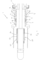
- Fig. 1
- shows cross section view of a male connector according to the present invention when locked relative to a female connector and waiting to receive a release tool;
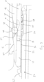
- Fig. 2
- shows a cross section view of the male and female connectors of
Fig. 1 when the release tool is fully inserted into the male connector; - Fig. 3
- shows an enlarged cross section view of a part of the male and female connectors and the release tool shown in
Fig. 2 ; - Fig. 4
- shows an enlarged view of the male and female connectors shown in
Fig. 1 when the release tool is pulled out from the male connector; - Fig. 5
- shows the male connector and release tool of
Fig. 1 when connected being removed from the female connector; - Fig. 6
- shows a perspective view of the male inserted in the female connector shown in
Fig. 1 with part cut away; - Fig. 7a
- shows a perspective cross section view of part of the male connector shown in
Fig. 1 when the male connector is in a locked configuration; - Fig. 7b
- shows a perspective cross section view of part of the male connector shown in
Fig. 1 when the male connector is in an unlocked configuration; - Fig. 8
- shows a perspective view of the female connector shown in
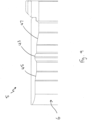
Fig. 1 with part cut away; and - Fig. 9
- shows a cross section view of a side of the female connector shown in
Fig. 1 . - Referring to the drawings there is shown a connection assembly 1 comprising a
male connector 3 and afemale connector 5. The female 5 connector defines atapered bore 6 into which themale connector 3 may be inserted and further comprises a flaredguide cone 7 at one opening to help guide themale connector 3 into the bore. Themale connector 3 also defines abore 8 so that when themale connector 3 andfemale connector 5 are coupled together, they both define a conduit through which a section of riser may extend. - The
male connector 3 comprises a substantiallycylindrical steel body 9 having aflange 11 at one end to facilitate attachment of themale connector 3 to a bend stiffener. Anose cone 13 is provided at the other end of themale connector 3 to protect themale connector 3 from damage upon insertion into thefemale connector 5 and also help to guide themale connector 3 into thefemale connector 5. A plurality ofspring tubes 15 extend axially from an end of thenose cone 13 toward the flange end of the male connector. Thespring tubes 15 serve as a support along which a substantially cylindrical hollowsteel locking sleeve 17 may travel. A plurality of bores equal to the number ofspring tubes 15 is formed in one end of thesleeve 17 to enable the sleeve to slide along the spring tubes axially with respect to themale body 9. A coil spring is retained within each bore and arranged to bias thesleeve 17 axially away from thenose cone 13. - A pair of diametrically
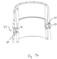
opposed grooves 19 is formed in thesleeve 17. Eachgroove 19 comprises a substantiallycylindrical depression 21 formed in the inner surface of thesleeve 17, ashallower channel 23 that extends from thecylindrical depression 21 along the inner surface of thesleeve 17 to the nose cone end of thesleeve 17 and a cut-out 25 that extends through thesleeve 17 from one side to the other and from the centre of thedepression 21 along the centre of thechannel 23 to the end of thesleeve 17. - Each
groove 19 is arranged to interact with acorresponding latch pin 27 that extends through thesleeve 17 from one side to the other via the cut-out 25 and that is spring loaded to bias thelatch pins 27 outwardly from thesleeve 17. Thelatch pin 27 comprises a substantiallycylindrical body 29 having a substantially flat,circular foot 31 that extends radially from one end of the body and that has a larger diameter than thebody 29. Acylindrical head section 33 is provided at the other end of thebody 29. Thehead section 33 also has a larger diameter than thebody 29 and is shaped to have a curved top to permit smooth contact with the walls of thefemale connector 5. - The
depression 21 on the inside of thesleeve 17 is dimensioned to receive at least part of thefoot 31 of thelatch pin 27 so that when thefoot 31 is received into thedepression 21, thelatch pin 27 and thesleeve 17 cannot move axially relative to one another. Thechannel 23 is dimensioned to have a width greater than the diameter of theplatform 31 whilst the cut-out 25 is dimensioned to have a width greater than thebody 29 of thelatch 27. The cut-out 25 andchannel 23 therefore permit thesleeve 17 to move along a controlled axial path along thebody 9 of themale connector 3, guided by thelatch pin 27. - Two diametrically
opposed apertures 35 are formed through thebody 9 of themale connector 3 to permit thelatch pin 27 to extend through thebody 9. Eachaperture 35 comprises two distinct sections, a first section arranged on the sleeve side of the aperture which has a diameter smaller than thehead 33 of thelatch pin 27 but larger than thebody 29 of thelatch pin 27 and a second section extending toward the external side of thebody 9 having a diameter larger than thehead 33 of thelatch pin 27. The interface between the first section and second section creates a stepped edge against which thelatch pin head 33 may abut to limit the extent to which thelatch pin 27 can be urged into thebore 8 of themale connector 3. Theapertures 35 restrict movement of the latch pins 27 to radial movement only so that when thesleeve 17 moves axially along thebody 9, the latch pins 27 do not move with thesleeve 17. - The
body 9 of themale connector 3 further comprises a plurality ofball apertures 37 which extend through thebody 9 and which are circumferentially spaced around thebody 9 along the same plane as thelatch pin apertures 35. Eachball aperture 37 is shaped to receive aspherical locking ball 39. The diameter of eachball aperture 37 reduces toward the external side of thebody 9 to less than the diameter of acorresponding locking ball 39 so as to limit the extent to which alocking ball 39 can project from theaperture 37 and to prevent the lockingballs 39 from falling out of theapertures 37. The lockingballs 39 are retained in theapertures 37 on the other side of thebody 9 by thesleeve 17 which always extends across theapertures 37. - The body facing side of the
sleeve 17 comprises a plurality of substantially hemi-spherical grooves 41 equivalent in number to the number ofball apertures 37 and henceballs 39 that extend through thebody 9. Theball grooves 41 are arranged such that, when thesleeve 17 is positioned toward thenose cone 13, theball grooves 41 are aligned with theball apertures 37 so that the lockingballs 39 can move into theball grooves 41. Thus, the lockingballs 39 have two operative positions, a first position in which the lockingballs 39 are urged out fromapertures 37 toward the external side of thebody 9 by the outer surface of the sleeve (as shown inFig. 7a ) and a second position in which the lockingballs 39 can move into the ball grooves 41 (as shown inFig. 4 ) from the ball apertures 37. - The
female connector 5 further comprises acircumferential groove 43 that extends around the internal surface of theconnector 5. The groove orring 43 is positioned such that when themale connector 3 is fully inserted into thefemale connector 5, thering 43 lies adj acent theball apertures 37 of themale connector 3. In this position, theballs 39 may be urged outwardly from theapertures 37 into thering 43 to help lock themale connector 3 relative to thefemale connector 5. A pair of taperededges ring 43 to provide abutments for corresponding tapered edges formed on thebody 9 of the male connector. The corresponding tapered edges help to correctly position thering 43 relative to theball apertures 37 when the tapered edges of therespective connectors - A
connector release tool 50 is also shown. Therelease tool 50 is dimensioned to fit within thebore 8 of themale connector 3 and is attachable to a work wire that facilitates insertion of the riser and release tool through themale connector 3. Therelease tool 50 comprises a substantiallycylindrical body 52 having a plurality of taperedgrooves 54 formed at spaced apart intervals around the outer surface of the extreme end of thebody 52. A spring loadedball cage sleeve 56 is arranged around the outside of thebody 52 and biased in an axial direction toward the end of thebody 52 at which the taperedgrooves 54 are formed. Theball cage sleeve 56 is movable between first and second positions along thebody 52. A plurality of substantiallycircular apertures 58 equivalent to the number of taperedgrooves 54 are formed through theball cage 56 and arranged to lie adjacent thegrooves 54 when the ball cage is positioned around the body in both the first and second positions and at every position there between. - A gripping
ball 60 is arranged in eachgroove 54 between thebody 52 and theball cage aperture 58 thereby restricting movement of thegripping balls 60 to the taperedgrooves 54. The tapering of thegrooves 54 is such that when theball cage sleeve 56 is in the biased, locked position as shown inFig. 3 , the gripping balls are urged up the tapered grooves by theball cage apertures 58 so that thegripping balls 60 project from theball cage apertures 58. Eachball cage aperture 58 is constricted toward the outside of thesleeve 56 so as to prevent the gripping balls from falling out from thegrooves 54. When thesleeve 56 is pulled against the action of the springs and moved back from the end of thetool 50, the gripping balls are urged toward the deeper end of thegrooves 54 so that the balls no longer project from the outer surface of thesleeve 56. - A
ball cage flange 62 or stop is positioned around the outside of the body of thetool 50 between theball cage sleeve 56 and the point of attachment to the work wire. Theball cage flange 62 is arranged to abut thenose cone 13 of the male connector upon insertion of thetool 50 into themale connector 3 and positioned such that when theball cage flange 62 abuts thenose cone 13, the tapered grooves and gripping balls lie adjacent therelease sleeve 17 of themale connector 3. - In use, a bend stiffener is fixed to the
flange 11 of themale connector 3 and the correspondingfemale connector 5 is fixed to an oil drilling platform or vessel. A work wire is attached to themale connector 3 to enable themale connector 3 to be pulled inside thefemale connector 5. Before insertion of themale connector 3 into thefemale connector 5, the lockingsleeve 17 is urged against the spring loading toward thenose cone 13 until the latch pins 27 are centred over the correspondingdepression 21. The spring loading on the latch pins 27 cause them to move radially outwardly until thelatch pin feet 31 sit within the depressions, thereby fixing thesleeve 17 relative to themale body 9. In this position, the latch pin heads 33 project outside of thebody 9 and the lockingballs 39 are free to sit within theball grooves 41. - Once the
sleeve 17 has been loaded, themale connector 3 is pulled inside thefemale connector 5 by the work wire. As insertion of themale connector 3 progresses, the internal tapered sides of thefemale connector 5 begin to squeeze the latch pins 27 in toward the bore of themale connector 3 until thelatch pin feet 31 are urged out from thedepressions 21. At this point, the spring loading on thesleeve 17 urges thesleeve 17 away from thenose cone 13. Movement of thesleeve 17 drives the lockingballs 39 out from theball grooves 41 and further out from theball apertures 37 so that the lockingballs 39 project from themale body 9. The tapering of thefemale connector 5 is such that the latch pins 27 and, hence,sleeve 17 are activated when theballs 39 are positioned adjacent the retainingring 43 on the inner wall of thefemale connector 5. Theballs 39 may therefore project from thebody 9 into thering 43 and be held in place by the forces exerted on the lockingballs 39 by the outer side of thesleeve 17 and the walls of the retainingring 43. When in this position, themale connector 3 is locked relative to thefemale connector 5 as shown clearly inFig. 3 . - When it is desired to unlock the
male connector 3 from thefemale connector 5, therelease tool 50 is attached to the work wire and any fitting attached to the riser and inserted into thebore 8 of themale connector 3. As therelease tool 50 is urged inside the male connector, theball cage sleeve 56 is urged back toward theball cage flange 62 by the walls of thenose cone 13. Movement of theball cage sleeve 56 toward theflange 62 urges thegripping balls 60 back down the tapered sides of thegripping ball grooves 54 until the balls lie within the walls of theball cage sleeve 56. Thus, therelease tool 50 can be inserted into themale connector 3 without interference from thegripping balls 60. - The
release tool 50 is further inserted into themale connector 3 until thestop 62 abuts the face of the maleconnector nose cone 13. A reduction in load on the work wire is then seen which indicates therelease tool 50 is fully inserted inside themale connector 3 and thetapered grooves 54 and lockingballs 60 are lined up with the lockingsleeve 17. In this position, thenose cone 13 no longer acts on theball cage sleeve 56 and the spring loading urges theball cage sleeve 56 back toward the end of therelease tool 50. Movement of theball cage sleeve 56 toward the end of therelease tool 50 urges thegripping balls 60 up the taperedgrooves 54 until thegripping balls 60 project from thesleeve 56 and engage the internal wall of the lockingsleeve 17. Once the grippingballs 60 engage the lockingsleeve 17, therelease tool 50 is pulled back out from themale connector 3. The friction between the lockingsleeve 17 andgripping balls 60 cause thegripping balls 60 to be urged further toward the end of therelease tool 50 thereby increasing the force with which thegripping balls 60 engage the lockingsleeve 17. Therelease tool 50 therefore pulls the lockingsleeve 17 toward thenose cone 13 against the spring loading of the lockingsleeve 17 until theball grooves 41 are adj acent the lockingballs 39 and thelatch pin feet 31 are centred over thedepressions 21. In this position, the lockingballs 39 are free to move into theball grooves 41 and themale connector 3 is therefore unlocked from the female connector. - Since the male and female connector assembly is intended in use to be substantially vertically oriented, the male connector and attached bend stiffener are pulled down against the action of the
gripping balls 60 by gravity. Consequently, therelease tool 50 andmale connector 3 remain coupled together even after themale connector 3 is unlatched from thefemale connector 5. The coupledrelease tool 50 andmale connector 3 are then lowered down out from the female connector 5 (as shown inFig. 5 ) and recovered. As the male connector is removed from the female connector, the latch pins no longer abut the inner surface of the female connector and are urged radially outwardly by their spring loading until thefeet 31 are seated within thedepressions 21. - The above embodiment is described by way of example only. Many variations are possible so long as they fall within the scope of the invention as defined in the appended claims.
Claims (8)
- A system comprising:a male connector (3), a female connector (5) and a release tool (50);the male connector (3) intended to be inserted into the female connector (5), the male connector defining a conduit (8) and comprising a locking means (39) operable to engage the female connector (5) to thereby lock the male connector (3) relative to the female connector and a release means (17) for unlocking the male connector to permit the male connector (3) to be separated from the female connector (5), wherein the release means (17) is accessible from within the conduit (8) and comprises a sleeve (17), the male connector (3) further comprising:
a substantially cylindrical steel body (9) comprising:a plurality of ball apertures (37) which extend through the body (9) and are circumferentially spaced around the body (9), each ball aperture (37) shaped to receive a spherical locking ball (39), the locking balls (39) being retained in the ball apertures (37) on the internal side of the body (9) of the male connector by an external side of the sleeve which always extends across the ball apertures (37) wherein the plurality of ball apertures (37) and the locking balls (39) define the locking means;the sleeve (17) comprising a plurality of substantially hemi-spherical grooves (41) on the external side of the sleeve facing the internal side of the body (9) of the male connector, said plurality of substantially hemi-spherical grooves (41) being equivalent in number to the number of ball apertures (37) and hence balls (39) that extend through the body (9) of the male connector,the female connector (5) comprising a circumferential groove (43) that extends around the internal surface of the female connector (5), the circumferential groove (43) being positioned such that when the male connector (3) is fully inserted into the female connector (5), the circumferential groove (43) lies adjacent the ball apertures (37) of the male connector (3),the release tool (50) comprising a release tool body (52) arranged to be inserted into the conduit and comprising an engagement means arranged to engage the release means (17) to unlock the male connector (3) relative to the female connector (5), the engagement means comprising one or more engagement means balls (60) or rollers for gripping the release means (17). - A system as claimed in claim 1wherein the engagement means is arranged, in use, to engage the male connector (3) and retain the male connector relative to the release tool (50) after the male connector is unlocked from the female connector (5).
- A system as claimed in claim 1 or claim 2, wherein the release tool further comprises a limiter that limits the distance the release tool may extend into the conduit so that when the release tool extends the fully permitted distance into the conduit, the engagement means is positioned to engage the release means (17).
- A system as claimed in claim 3, wherein the limiter comprises a stop, preferably comprising a flange (62), that is intended to abut a part of the male or female connector.
- A system as claimed in any preceding claim, wherein each of the one or more balls (60) or rollers of the engagement means is urgable into contact with release means (17) and arrangable to wedge or bite into the release means (17).
- A system as claimed in any preceding claim, wherein the release tool further comprises one or more tapered grooves (54) and wherein each of the one or more balls (60) or rollers of the engagement means is seated in a corresponding tapered groove and limited to movement along the tapered groove by a release tool sleeve (56) that extends over each of the one or more tapered grooves, the release tool sleeve (56) comprising a release tool sleeve aperture (58) for each ball (60) or roller of the engagement means so that each of the one or more balls or rollers of the engagement means can extend at least partially through the release tool sleeve.
- A system as claimed in claim 6, wherein each of the one or more tapered grooves (54) is shaped such that when the ball (60) or roller of the engagement means is in one position in the tapered groove it extends at least partially through the aperture (58) of the release tool sleeve (56) and when in another position the ball or roller of the engagement means is substantially inside the release tool sleeve.
- A system as claimed in claim 7, wherein the release tool sleeve (56) is biased toward a position in which each of the one or more balls (60) or rollers of the engagement means is urged at least partially through each of the one or more apertures (58) of the release tool sleeve.
Applications Claiming Priority (2)
| Application Number | Priority Date | Filing Date | Title |
|---|---|---|---|
| GBGB1321416.8A GB201321416D0 (en) | 2013-12-04 | 2013-12-04 | Apparatus and method for disconnecting male and female connectors |
| PCT/GB2014/053612 WO2015082930A2 (en) | 2013-12-04 | 2014-12-04 | Apparatus and method for disconnecting male and female connectors |
Publications (3)
| Publication Number | Publication Date |
|---|---|
| EP3077616A2 EP3077616A2 (en) | 2016-10-12 |
| EP3077616B1 true EP3077616B1 (en) | 2023-06-07 |
| EP3077616C0 EP3077616C0 (en) | 2023-06-07 |
Family
ID=49979799
Family Applications (1)
| Application Number | Title | Priority Date | Filing Date |
|---|---|---|---|
| EP14809690.2A Active EP3077616B1 (en) | 2013-12-04 | 2014-12-04 | Apparatus and method for disconnecting male and female subsea connectors |
Country Status (7)
| Country | Link |
|---|---|
| US (1) | US10287859B2 (en) |
| EP (1) | EP3077616B1 (en) |
| AU (1) | AU2014358881B2 (en) |
| BR (1) | BR112016011941B1 (en) |
| CA (1) | CA2931011C (en) |
| GB (1) | GB201321416D0 (en) |
| WO (1) | WO2015082930A2 (en) |
Families Citing this family (2)
| Publication number | Priority date | Publication date | Assignee | Title |
|---|---|---|---|---|
| WO2025075603A1 (en) * | 2023-10-02 | 2025-04-10 | Halliburton Energy Services, Inc. | Wet mate carrier for radial deployment of downhole wet mate connector |
| US12534967B2 (en) * | 2023-12-07 | 2026-01-27 | National Coupling Company, Inc. | System and method for supporting risers from floating vessel |
Citations (2)
| Publication number | Priority date | Publication date | Assignee | Title |
|---|---|---|---|---|
| US3845819A (en) * | 1972-04-27 | 1974-11-05 | Rech Activities Petrolieres En | Cable tool for setting liners |
| US20070261857A1 (en) * | 2006-04-25 | 2007-11-15 | Canrig Drilling Technology Ltd. | Tubular running tool |
Family Cites Families (29)
| Publication number | Priority date | Publication date | Assignee | Title |
|---|---|---|---|---|
| US2409811A (en) * | 1941-04-04 | 1946-10-22 | Guiberson Corp | Setting and releasing tool |
| US2665928A (en) * | 1948-10-27 | 1954-01-12 | Case Co J I | Coupling |
| US3539205A (en) * | 1968-10-09 | 1970-11-10 | Gifford Hill Western | Irrigation pipe system and pipe units therefor |
| US3948545A (en) * | 1974-03-11 | 1976-04-06 | Mcevoy Oilfield Equipment Co. | Mechanically operated breech block |
| US4307902A (en) | 1979-07-13 | 1981-12-29 | Otis Engineering Corp. | Riser connector |
| US4411455A (en) | 1980-07-31 | 1983-10-25 | Schnatzmeyer Mark A | Riser connector |
| US4399877A (en) * | 1981-04-17 | 1983-08-23 | Nl Sperry Sun, Inc. | Continuous borehole telemetry system and method |
| US4664148A (en) * | 1986-02-03 | 1987-05-12 | Clevite Industries Inc. | Quick disconnect coupling with a lockable valve actuator |
| GB2203508A (en) * | 1987-04-16 | 1988-10-19 | Shell Int Research | System and method for securing a marine riser to a floating structure |
| US4787557A (en) * | 1988-01-15 | 1988-11-29 | Jackson Miles E | Solid set spike irrigation head connecting device |
| FR2689603B1 (en) * | 1992-04-07 | 1994-05-20 | Coflexip | DEVICE FOR MOUNTING A FLEXIBLE LINE COMPRISING A CURVATORY LIMITER. |
| BR9605669C1 (en) * | 1996-11-22 | 2000-03-21 | Petroleo Brasileiro Sa | submarine to a structure located on the surface. |
| NO308785B1 (en) * | 1997-02-20 | 2000-10-30 | Norske Stats Oljeselskap | Vessels for use in the production and / or storage of hydrocarbons |
| US6323313B1 (en) * | 1999-06-01 | 2001-11-27 | The University Of Washington | Annexin derivative with endogenous chelation sites |
| FR2807814B1 (en) * | 2000-04-17 | 2002-07-12 | Techlam | DEVICE FOR CONNECTING A SUBMERSIBLE FLUID TRANSPORT LINE |
| US6536527B2 (en) * | 2000-05-16 | 2003-03-25 | Abb Vetco Gray Inc. | Connection system for catenary riser |
| NO325132B1 (en) * | 2004-03-31 | 2008-02-04 | Aker Subsea As | connector |
| AU2005294434B2 (en) * | 2004-10-06 | 2009-03-19 | Single Buoy Moorings, Inc. | Riser connector |
| GB0506406D0 (en) * | 2005-03-30 | 2005-05-04 | Crp Group Ltd | Connector |
| GB2424932A (en) * | 2005-04-06 | 2006-10-11 | Bsw Ltd | Gripping device with helically or randomly arranged members to avoid excessive grooving |
| FR2890719B1 (en) * | 2005-09-14 | 2007-10-12 | Staubli Faverges Sca | QUICK CONNECTION OF SECURITY FOR THE JOINING OF TWO PIPES |
| US7967070B2 (en) * | 2006-07-12 | 2011-06-28 | Deep Sea Technologies, Inc. | Diverless connector for bend restrictors and/or bend stiffeners |
| GB0623517D0 (en) | 2006-11-25 | 2007-01-03 | Balltec Ltd | A connector |
| US20090078425A1 (en) * | 2007-09-25 | 2009-03-26 | Seahorse Equipment Corp | Flexible hang-off arrangement for a catenary riser |
| GB2463471B (en) | 2008-09-11 | 2012-05-16 | First Subsea Ltd | A Riser Connector |
| FR2979658B1 (en) * | 2011-09-07 | 2015-07-17 | Technip France | METHOD FOR CONNECTING A FLEXIBLE LINE TO A STRUCTURE OF A FLUID OPERATING INSTALLATION AND CONNECTING DEVICE THEREFOR |
| US9010445B2 (en) * | 2011-12-09 | 2015-04-21 | Tesco Corporation | Ball grab tubular handling |
| FR2998637B1 (en) * | 2012-11-23 | 2015-06-26 | Staubli Sa Ets | RAPID COUPLING FEMALE ELEMENT AND RAPID CONNECTION INCORPORATING SUCH A MEMBER |
| GB2508919A (en) * | 2012-12-17 | 2014-06-18 | Flexible Engineered Solutions Ltd | Subsea connector assembly |
-
2013
- 2013-12-04 GB GBGB1321416.8A patent/GB201321416D0/en not_active Ceased
-
2014
- 2014-12-04 CA CA2931011A patent/CA2931011C/en active Active
- 2014-12-04 EP EP14809690.2A patent/EP3077616B1/en active Active
- 2014-12-04 US US15/037,986 patent/US10287859B2/en active Active
- 2014-12-04 AU AU2014358881A patent/AU2014358881B2/en active Active
- 2014-12-04 BR BR112016011941-0A patent/BR112016011941B1/en active IP Right Grant
- 2014-12-04 WO PCT/GB2014/053612 patent/WO2015082930A2/en not_active Ceased
Patent Citations (2)
| Publication number | Priority date | Publication date | Assignee | Title |
|---|---|---|---|---|
| US3845819A (en) * | 1972-04-27 | 1974-11-05 | Rech Activities Petrolieres En | Cable tool for setting liners |
| US20070261857A1 (en) * | 2006-04-25 | 2007-11-15 | Canrig Drilling Technology Ltd. | Tubular running tool |
Also Published As
| Publication number | Publication date |
|---|---|
| BR112016011941B1 (en) | 2022-02-08 |
| BR112016011941A2 (en) | 2017-09-19 |
| CA2931011C (en) | 2021-11-30 |
| EP3077616C0 (en) | 2023-06-07 |
| AU2014358881A1 (en) | 2016-06-09 |
| AU2014358881B2 (en) | 2018-07-05 |
| GB201321416D0 (en) | 2014-01-15 |
| WO2015082930A2 (en) | 2015-06-11 |
| EP3077616A2 (en) | 2016-10-12 |
| US20160290108A1 (en) | 2016-10-06 |
| US10287859B2 (en) | 2019-05-14 |
| CA2931011A1 (en) | 2015-06-11 |
| WO2015082930A3 (en) | 2015-10-08 |
Similar Documents
| Publication | Publication Date | Title |
|---|---|---|
| EP3475157B1 (en) | A mooring connector | |
| EP2932013B1 (en) | Subsea connector assembly | |
| US8573305B2 (en) | Pull-head release mechanism for bend stiffener connector | |
| JP2620485B2 (en) | Apparatus for attaching a flexible line with a bend limiting device | |
| MX2011002619A (en) | A riser connector. | |
| BR102018011452B1 (en) | COUPLING SYSTEM BETWEEN A CURVATURE HARDENER AND A BELL MOUTH COMPRISING A PLURALITY OF LOCKING MECHANISMS | |
| US20030049076A1 (en) | Method for connection of underwater pipelines and a tool for such connection | |
| US9114858B2 (en) | Subsea anchoring assembly | |
| EP4004334B1 (en) | Horizontal connector system and method | |
| GB2424684A (en) | Pipe connector with bend stiffening portion | |
| US20230228159A1 (en) | Support for risers and method for coupling and uncoupling | |
| US10287859B2 (en) | Apparatus and method for disconnecting male and female connectors | |
| US4451056A (en) | Remotely operated underwater tension connector | |
| US10781943B2 (en) | Abandonment and recovery system for a subsea pipeline | |
| US12534967B2 (en) | System and method for supporting risers from floating vessel | |
| WO2016028162A1 (en) | Improvements relating to disconnecting flexible elongate members such as cables | |
| OA16223A (en) | A riser connector. |
Legal Events
| Date | Code | Title | Description |
|---|---|---|---|
| PUAI | Public reference made under article 153(3) epc to a published international application that has entered the european phase |
Free format text: ORIGINAL CODE: 0009012 |
|
| 17P | Request for examination filed |
Effective date: 20160623 |
|
| AK | Designated contracting states |
Kind code of ref document: A2 Designated state(s): AL AT BE BG CH CY CZ DE DK EE ES FI FR GB GR HR HU IE IS IT LI LT LU LV MC MK MT NL NO PL PT RO RS SE SI SK SM TR |
|
| AX | Request for extension of the european patent |
Extension state: BA ME |
|
| DAX | Request for extension of the european patent (deleted) | ||
| STAA | Information on the status of an ep patent application or granted ep patent |
Free format text: STATUS: EXAMINATION IS IN PROGRESS |
|
| 17Q | First examination report despatched |
Effective date: 20180215 |
|
| GRAP | Despatch of communication of intention to grant a patent |
Free format text: ORIGINAL CODE: EPIDOSNIGR1 |
|
| STAA | Information on the status of an ep patent application or granted ep patent |
Free format text: STATUS: GRANT OF PATENT IS INTENDED |
|
| INTG | Intention to grant announced |
Effective date: 20221004 |
|
| GRAS | Grant fee paid |
Free format text: ORIGINAL CODE: EPIDOSNIGR3 |
|
| GRAA | (expected) grant |
Free format text: ORIGINAL CODE: 0009210 |
|
| STAA | Information on the status of an ep patent application or granted ep patent |
Free format text: STATUS: THE PATENT HAS BEEN GRANTED |
|
| AK | Designated contracting states |
Kind code of ref document: B1 Designated state(s): AL AT BE BG CH CY CZ DE DK EE ES FI FR GB GR HR HU IE IS IT LI LT LU LV MC MK MT NL NO PL PT RO RS SE SI SK SM TR |
|
| REG | Reference to a national code |
Ref country code: GB Ref legal event code: FG4D |
|
| REG | Reference to a national code |
Ref country code: CH Ref legal event code: EP Ref country code: AT Ref legal event code: REF Ref document number: 1575668 Country of ref document: AT Kind code of ref document: T Effective date: 20230615 Ref country code: DE Ref legal event code: R096 Ref document number: 602014087226 Country of ref document: DE |
|
| U01 | Request for unitary effect filed |
Effective date: 20230622 |
|
| REG | Reference to a national code |
Ref country code: NO Ref legal event code: T2 Effective date: 20230607 |
|
| U07 | Unitary effect registered |
Designated state(s): AT BE BG DE DK EE FI FR IT LT LU LV MT NL PT SE SI Effective date: 20230707 |
|
| REG | Reference to a national code |
Ref country code: LT Ref legal event code: MG9D |
|
| PG25 | Lapsed in a contracting state [announced via postgrant information from national office to epo] |
Ref country code: ES Free format text: LAPSE BECAUSE OF FAILURE TO SUBMIT A TRANSLATION OF THE DESCRIPTION OR TO PAY THE FEE WITHIN THE PRESCRIBED TIME-LIMIT Effective date: 20230607 |
|
| PG25 | Lapsed in a contracting state [announced via postgrant information from national office to epo] |
Ref country code: RS Free format text: LAPSE BECAUSE OF FAILURE TO SUBMIT A TRANSLATION OF THE DESCRIPTION OR TO PAY THE FEE WITHIN THE PRESCRIBED TIME-LIMIT Effective date: 20230607 Ref country code: HR Free format text: LAPSE BECAUSE OF FAILURE TO SUBMIT A TRANSLATION OF THE DESCRIPTION OR TO PAY THE FEE WITHIN THE PRESCRIBED TIME-LIMIT Effective date: 20230607 Ref country code: GR Free format text: LAPSE BECAUSE OF FAILURE TO SUBMIT A TRANSLATION OF THE DESCRIPTION OR TO PAY THE FEE WITHIN THE PRESCRIBED TIME-LIMIT Effective date: 20230908 |
|
| PG25 | Lapsed in a contracting state [announced via postgrant information from national office to epo] |
Ref country code: SK Free format text: LAPSE BECAUSE OF FAILURE TO SUBMIT A TRANSLATION OF THE DESCRIPTION OR TO PAY THE FEE WITHIN THE PRESCRIBED TIME-LIMIT Effective date: 20230607 |
|
| PG25 | Lapsed in a contracting state [announced via postgrant information from national office to epo] |
Ref country code: IS Free format text: LAPSE BECAUSE OF FAILURE TO SUBMIT A TRANSLATION OF THE DESCRIPTION OR TO PAY THE FEE WITHIN THE PRESCRIBED TIME-LIMIT Effective date: 20231007 |
|
| U20 | Renewal fee for the european patent with unitary effect paid |
Year of fee payment: 10 Effective date: 20231221 |
|
| PG25 | Lapsed in a contracting state [announced via postgrant information from national office to epo] |
Ref country code: SM Free format text: LAPSE BECAUSE OF FAILURE TO SUBMIT A TRANSLATION OF THE DESCRIPTION OR TO PAY THE FEE WITHIN THE PRESCRIBED TIME-LIMIT Effective date: 20230607 Ref country code: SK Free format text: LAPSE BECAUSE OF FAILURE TO SUBMIT A TRANSLATION OF THE DESCRIPTION OR TO PAY THE FEE WITHIN THE PRESCRIBED TIME-LIMIT Effective date: 20230607 Ref country code: RO Free format text: LAPSE BECAUSE OF FAILURE TO SUBMIT A TRANSLATION OF THE DESCRIPTION OR TO PAY THE FEE WITHIN THE PRESCRIBED TIME-LIMIT Effective date: 20230607 Ref country code: IS Free format text: LAPSE BECAUSE OF FAILURE TO SUBMIT A TRANSLATION OF THE DESCRIPTION OR TO PAY THE FEE WITHIN THE PRESCRIBED TIME-LIMIT Effective date: 20231007 Ref country code: CZ Free format text: LAPSE BECAUSE OF FAILURE TO SUBMIT A TRANSLATION OF THE DESCRIPTION OR TO PAY THE FEE WITHIN THE PRESCRIBED TIME-LIMIT Effective date: 20230607 |
|
| PG25 | Lapsed in a contracting state [announced via postgrant information from national office to epo] |
Ref country code: PL Free format text: LAPSE BECAUSE OF FAILURE TO SUBMIT A TRANSLATION OF THE DESCRIPTION OR TO PAY THE FEE WITHIN THE PRESCRIBED TIME-LIMIT Effective date: 20230607 |
|
| REG | Reference to a national code |
Ref country code: DE Ref legal event code: R097 Ref document number: 602014087226 Country of ref document: DE |
|
| PLBE | No opposition filed within time limit |
Free format text: ORIGINAL CODE: 0009261 |
|
| STAA | Information on the status of an ep patent application or granted ep patent |
Free format text: STATUS: NO OPPOSITION FILED WITHIN TIME LIMIT |
|
| 26N | No opposition filed |
Effective date: 20240308 |
|
| REG | Reference to a national code |
Ref country code: CH Ref legal event code: PL |
|
| PG25 | Lapsed in a contracting state [announced via postgrant information from national office to epo] |
Ref country code: MC Free format text: LAPSE BECAUSE OF FAILURE TO SUBMIT A TRANSLATION OF THE DESCRIPTION OR TO PAY THE FEE WITHIN THE PRESCRIBED TIME-LIMIT Effective date: 20230607 |
|
| PG25 | Lapsed in a contracting state [announced via postgrant information from national office to epo] |
Ref country code: MC Free format text: LAPSE BECAUSE OF FAILURE TO SUBMIT A TRANSLATION OF THE DESCRIPTION OR TO PAY THE FEE WITHIN THE PRESCRIBED TIME-LIMIT Effective date: 20230607 |
|
| REG | Reference to a national code |
Ref country code: IE Ref legal event code: MM4A |
|
| PG25 | Lapsed in a contracting state [announced via postgrant information from national office to epo] |
Ref country code: IE Free format text: LAPSE BECAUSE OF NON-PAYMENT OF DUE FEES Effective date: 20231204 |
|
| PG25 | Lapsed in a contracting state [announced via postgrant information from national office to epo] |
Ref country code: CH Free format text: LAPSE BECAUSE OF NON-PAYMENT OF DUE FEES Effective date: 20231231 |
|
| PG25 | Lapsed in a contracting state [announced via postgrant information from national office to epo] |
Ref country code: IE Free format text: LAPSE BECAUSE OF NON-PAYMENT OF DUE FEES Effective date: 20231204 Ref country code: CH Free format text: LAPSE BECAUSE OF NON-PAYMENT OF DUE FEES Effective date: 20231231 |
|
| U20 | Renewal fee for the european patent with unitary effect paid |
Year of fee payment: 11 Effective date: 20241230 |
|
| PG25 | Lapsed in a contracting state [announced via postgrant information from national office to epo] |
Ref country code: CY Free format text: LAPSE BECAUSE OF FAILURE TO SUBMIT A TRANSLATION OF THE DESCRIPTION OR TO PAY THE FEE WITHIN THE PRESCRIBED TIME-LIMIT; INVALID AB INITIO Effective date: 20141204 |
|
| PG25 | Lapsed in a contracting state [announced via postgrant information from national office to epo] |
Ref country code: HU Free format text: LAPSE BECAUSE OF FAILURE TO SUBMIT A TRANSLATION OF THE DESCRIPTION OR TO PAY THE FEE WITHIN THE PRESCRIBED TIME-LIMIT; INVALID AB INITIO Effective date: 20141204 |
|
| PG25 | Lapsed in a contracting state [announced via postgrant information from national office to epo] |
Ref country code: TR Free format text: LAPSE BECAUSE OF FAILURE TO SUBMIT A TRANSLATION OF THE DESCRIPTION OR TO PAY THE FEE WITHIN THE PRESCRIBED TIME-LIMIT Effective date: 20230607 |
|
| PGFP | Annual fee paid to national office [announced via postgrant information from national office to epo] |
Ref country code: GB Payment date: 20251222 Year of fee payment: 12 |
|
| U20 | Renewal fee for the european patent with unitary effect paid |
Year of fee payment: 12 Effective date: 20251222 |
|
| PGFP | Annual fee paid to national office [announced via postgrant information from national office to epo] |
Ref country code: NO Payment date: 20251230 Year of fee payment: 12 |