EP3076760A1 - Power supply apparatus for led lighting - Google Patents
Power supply apparatus for led lighting Download PDFInfo
- Publication number
- EP3076760A1 EP3076760A1 EP14865046.8A EP14865046A EP3076760A1 EP 3076760 A1 EP3076760 A1 EP 3076760A1 EP 14865046 A EP14865046 A EP 14865046A EP 3076760 A1 EP3076760 A1 EP 3076760A1
- Authority
- EP
- European Patent Office
- Prior art keywords
- power supply
- connector
- supply apparatus
- wire
- resistor
- Prior art date
- Legal status (The legal status is an assumption and is not a legal conclusion. Google has not performed a legal analysis and makes no representation as to the accuracy of the status listed.)
- Withdrawn
Links
Images




Classifications
-
- F—MECHANICAL ENGINEERING; LIGHTING; HEATING; WEAPONS; BLASTING
- F21—LIGHTING
- F21V—FUNCTIONAL FEATURES OR DETAILS OF LIGHTING DEVICES OR SYSTEMS THEREOF; STRUCTURAL COMBINATIONS OF LIGHTING DEVICES WITH OTHER ARTICLES, NOT OTHERWISE PROVIDED FOR
- F21V23/00—Arrangement of electric circuit elements in or on lighting devices
- F21V23/02—Arrangement of electric circuit elements in or on lighting devices the elements being transformers, impedances or power supply units, e.g. a transformer with a rectifier
- F21V23/023—Power supplies in a casing
-
- H—ELECTRICITY
- H05—ELECTRIC TECHNIQUES NOT OTHERWISE PROVIDED FOR
- H05B—ELECTRIC HEATING; ELECTRIC LIGHT SOURCES NOT OTHERWISE PROVIDED FOR; CIRCUIT ARRANGEMENTS FOR ELECTRIC LIGHT SOURCES, IN GENERAL
- H05B47/00—Circuit arrangements for operating light sources in general, i.e. where the type of light source is not relevant
-
- F—MECHANICAL ENGINEERING; LIGHTING; HEATING; WEAPONS; BLASTING
- F21—LIGHTING
- F21V—FUNCTIONAL FEATURES OR DETAILS OF LIGHTING DEVICES OR SYSTEMS THEREOF; STRUCTURAL COMBINATIONS OF LIGHTING DEVICES WITH OTHER ARTICLES, NOT OTHERWISE PROVIDED FOR
- F21V23/00—Arrangement of electric circuit elements in or on lighting devices
- F21V23/06—Arrangement of electric circuit elements in or on lighting devices the elements being coupling devices, e.g. connectors
-
- F—MECHANICAL ENGINEERING; LIGHTING; HEATING; WEAPONS; BLASTING
- F21—LIGHTING
- F21V—FUNCTIONAL FEATURES OR DETAILS OF LIGHTING DEVICES OR SYSTEMS THEREOF; STRUCTURAL COMBINATIONS OF LIGHTING DEVICES WITH OTHER ARTICLES, NOT OTHERWISE PROVIDED FOR
- F21V31/00—Gas-tight or water-tight arrangements
- F21V31/005—Sealing arrangements therefor
-
- H—ELECTRICITY
- H05—ELECTRIC TECHNIQUES NOT OTHERWISE PROVIDED FOR
- H05B—ELECTRIC HEATING; ELECTRIC LIGHT SOURCES NOT OTHERWISE PROVIDED FOR; CIRCUIT ARRANGEMENTS FOR ELECTRIC LIGHT SOURCES, IN GENERAL
- H05B45/00—Circuit arrangements for operating light-emitting diodes [LED]
- H05B45/30—Driver circuits
- H05B45/36—Circuits for reducing or suppressing harmonics, ripples or electromagnetic interferences [EMI]
Definitions
- the present invention relates to an apparatus for supplying power to an LED light.
- LED light-emitting diode
- An LED driving circuit may implement various circuits depending on a design object.
- the LED driving circuit has a strong influence on efficiency of a driving circuit and the lifespan of an LED depending on uses, the driving characteristic of an LED, and the configuration of an LED array.
- the power supply apparatus functions to receive external power and to convert the external power into power for driving the LED light.
- a constant current type power supply apparatus converts an AC applied thereto into a direct current (DC) and supplies the DC to an LED light, that is, a light source.
- DC direct current
- a power supply apparatus for driving the LED light is designed in various ways from several tens of watts (W) to several hundreds of watts (W). To secure insulation with the outside becomes more important because a danger of an electric shock is increased as the capacity is increased.
- a current light device requires more than it turns on a light using a switch. That is, a current light device is developing into a more advanced form, such as producing various atmospheres depending on indoor uses or automatically adjusting luminous intensity properly depending on surrounding luminous intensity.
- a light device that evolves as described above is internationally used based on digital addressable lighting interface (DALI) communication.
- DIALI digital addressable lighting interface
- An object of the present invention is to solve waste and inconvenience in which a power supply apparatus must be replaced when an LED light is replaced.
- An object of the present invention is to show the same performance as that obtained when a power supply apparatus is replaced by connecting a separate resistor and changing impedance of a voltage sensing resistor (RSET) through a simple manipulation and to increase light management efficiency by minimizing a cost.
- RSET voltage sensing resistor
- An object of the present invention is to enable a user to easily change an output current of a power supply apparatus through a simple manipulation in which a connector connected to the voltage sensing resistor (RSET) of the power supply apparatus is exposed to the outside and an external connector is inserted into the connector.
- RSET voltage sensing resistor
- An object of the present invention is to prevent a short attributable to the erroneous connection of an external connector by designing an external shape so that the connector of a power supply apparatus and the external connector are engaged.
- An object of the present invention is to prevent deterioration or aging attributable to moisture or an external impact and to reduce a danger of an electric shock by dually insulating a power wire included in a power supply apparatus for an LED light.
- An object of the present invention is to prevent the penetration of moisture or dust into a housing and to block the leakage of a molding solution coated on the inside of the housing by shielding the space between a power wire and the housing through a gasket.
- An object of the present invention is to improve the mobility of a power wire having a widened width through dual insulation by providing grooves in some region of a gasket coupled to the power wire, thereby facilitating the connection of the power wire and a circuit when a power supply apparatus is fabricated.
- An object of the present invention is to implement digital control complying with different needs of users because a program for outputting a digital control signal is recorded on an MCU connected to a printed circuit board mounted on a power supply apparatus.
- An object of the present invention is to freely change a program recorded on an MCU by mounting a connector connected to the MCU on a power supply apparatus, opening part of a housing so that the connector is exposed, and connecting an external terminal to the connector.
- An object of the present invention is to protect parts of a power supply apparatus against an external environment, such as rainwater and dust, and to extend the lifespan of the power supply apparatus by inserting a gasket from the outside of a housing and connecting the gasket to a connector.
- a power supply apparatus for an LED light including a printed circuit board on which a circuit converting input power into output power for driving an LED light has been printed, an MCU which includes a driving voltage port, a ground port, and a voltage sensing port, which is connected to the printed circuit board, and which transfers a control signal for converting an electric current applied to the LED light to the circuit based on a voltage inputted to the voltage sensing port, a first resistor which has one end connected to the driving voltage port and has the other end connected to the voltage sensing node, a second resistor which has one end connected to the ground port and has the other end connected to the voltage sensing node, a sensing wire which has one end connected to the voltage sensing port and has the other end connected to the voltage sensing node, a first wire which has one end connected to the one end of the first resistor and has the other end open, a second wire which has one end connected to the one end of the second resistor and has the other end
- an opening portion may be provided on one side of the housing, and the other ends of the first to the third wires may be extended to the outside of the housing through the opening portion.
- the power supply apparatus may further include a gasket which is coupled to the stop portions of the first to the third wires and closely adheres to a designated area of the outer surface and inner surface of the opening portion.
- the power supply apparatus may further include a first connector including a coupling unit to which the other ends of the first to the third wires are coupled and first to third guide grooves into which the pins of a second connector are inserted.
- the first to the third guide grooves may be extended up to the other ends of the first to the third wires, respectively.
- At least one corner of the body of the first connector may be bent or protruded in response to a shape of the body of the second connector or at least one corner of the guide groove may be bent or protruded in response to a shape of the pin of the second connector so that an erroneous connection of the second connector is blocked.
- the second connector includes first and second pins coupled together.
- the first pin may be inserted into the third guide groove, and the second pin may be inserted into any one of the first and the second guide grooves.
- first and the second pins may electrically connect the other end of the third wire to the other end of any one of the first wire and the second wire.
- a power supply apparatus for an LED light including a printed circuit board on which a circuit converting input power into output power for driving an LED light has been printed, an MCU which includes a driving voltage port, a ground port, and a voltage sensing port, which is connected to the printed circuit board, and which transfers a control signal for converting an electric current applied to the LED light to the circuit based on a voltage inputted to the voltage sensing port, a first resistor which has one end connected to the driving voltage port and has the other end connected to the voltage sensing node, a second resistor which has one end connected to the ground port and has the other end connected to the voltage sensing node, a sensing wire which has one end connected to the voltage sensing port and has the other end connected to the voltage sensing node, a first wire which has one end connected to the one end of the first resistor and has the other end open, a second wire which has one end connected to the one end of the second resistor and has the other end
- the power supply apparatus may further include a first connector including a coupling unit to which the other ends of the first to the third wires are coupled and first to third guide grooves into which the pins of a second connector are inserted.
- the first to the third guide grooves may be connected to the other ends of the first to the third wires, respectively.
- the second connector may include a third resistor and first and second pins connected to both ends of the third resistor.
- the first pin may be inserted into the third guide groove.
- the second pin may be inserted into any one of the first and the second guide grooves.
- first and the second pins may electrically connect the other end of the third wire to the other end of any one of the first wire and the second wire.
- a power supply apparatus for an LED light having improved insulation performance including a power wire which has one end connected to a printed circuit board, a printed circuit board on which a circuit for converting input power supplied by the power wire into output power for driving an exterior LED light has been printed, and a housing which accommodates the printed circuit board and includes an opening portion through which the other end of the power wire passes and which is drawn to the outside of the housing.
- the power wire includes a dual insulation unit and a power supply conductor connected to an external power source and isolated from the outside by the dual insulation unit.
- the dual insulation unit may include first insulating means which is made of a first insulating material and surrounds the power supply conductor and second insulating means which is made of a second insulating material and surrounds the first insulating means.
- the power supply apparatus may further include a gasket which is coupled to the circumference of the second insulating means and includes a fitting groove inserted into the edge of the opening portion.
- the gasket may further include reinforcement means which is connected to one of both sides of the gasket and surrounds the second insulating means in the length direction of the power wire.
- the reinforcement means may include a mobility groove for facilitating a bending of the power wire.
- the gasket may be made of PVC having a relative temperature index (RTI) of 90°C.
- RTI relative temperature index
- a friction force corresponding to 5 kgf (kilogram-force) for 1 hour or more at 100°C may be generated at a portion where the gasket and the second insulating means are coupled.
- a power supply apparatus for an LED light including a printed circuit board on which a circuit converting input power into output power for driving an LED light has been printed, an MCU on which a program outputting a control signal for the LED light is recorded, which is connected to the printed circuit board, and which transfers the control signal to the circuit, a connector which has one side connected to an external terminal, has the other side connected to the MCU, and transfers a program conversion signal received from the external terminal to the MCU, and a housing which accommodates the printed circuit board, the MCU, and the connector and has an opening portion for connecting the external terminal and the connector on one side of the housing.
- the connector may include a plurality of connector pins. A designated area between one side and the other side of the plurality of connector pins may have been subjected to bending processing.
- the connector may further include pin support means including a plurality of through holes spaced apart from each other at a designated interval. The number of through holes may be identical with the number of connector pins.
- Each of the connector pins may be coupled to the inside of each of the through holes, and one side and the other side of each of the connector pins may be protruded to the outside of the through hole.
- the power supply apparatus may further include a gasket including a body and a plurality of insertion grooves spaced apart from each other at an interval identical with the designated interval at one end of the body.
- the number of insertion grooves may be identical with the number of connector pins.
- the gasket may further include packing means extended from the other end of the body in a direction orthogonal to the length direction of the body. A separation groove may be provided on the inside of the packing means.
- the gasket may be made of a silicon-series compound.
- the connector may include first to fifth connector pins connected to the external terminal. The first connector pin may receive information about an operating frequency. The second connector pin may receive a program conversion signal synchronized with the operating frequency. The third connector pin may ground the external terminal and the MCU. The fourth connector pin may supply power to the external terminal. The fifth connector pin may receive a reset command for information recorded on the MCU.
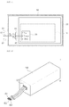
- FIG. 1 is a plan view of a power supply apparatus for an LED light according to an embodiment of the present invention.
- the power supply apparatus for an LED light includes a printed circuit board 20, a microcontroller unit (MCU) 30, a first resistor R1, a second resistor R2, a sensing wire 64, a first wire 61, a second wire 62, a third wire 63, and a housing 50.
- MCU microcontroller unit
- a circuit 10 means a circuit for converting external power into output power for driving an LED light connected to the power supply apparatus.
- a diode for example, a diode, an EMI filter, a capacitor, an inductor, a register, an integrated circuit (IC), a heat sink, a transistor, an operation amplifier, etc. may be included in the circuit.
- IC integrated circuit
- a heat sink for example, a transistor, an operation amplifier, etc.
- the printed circuit board 20 means a thin plate which is electrically connected to the circuit 10 by soldering, etc. and to which the circuit 10 is fixed.
- One side of the printed circuit board 20 is commonly used, but the present invention is not limited thereto. Both sides of the printed circuit board 20 may be used, if necessary.
- the MCU 30 is a term meaning a non-memory semiconductor part which is responsible for the brain of an electronic product and controls various functions from a simple time schedule to a specific function.
- a program for outputting a control signal for an LED light is recorded on the MCU 30, and the MCU 30 is connected to the printed circuit board 20.
- the MCU 30 includes a driving voltage port VIN, a voltage sensing port VSENSE, and a ground port GND.
- a driving voltage for driving the MCU 30 is applied to the driving voltage port VIN.
- Voltages that belong to the driving voltage applied to the driving voltage port VIN and that are divided by the first to the third resistors R3 are sensed at the voltage sensing port VSENSE.
- the MCU 30 is grounded through the ground port GND.
- the MCU 30 generates a control signal in accordance with a program for converting an electric current applied to the LED light based on a voltage inputted to the voltage sensing port VSENSE and transfers the control signal to the circuit 10.
- the MCU may generate a control signal which performs control so that an electric current of 700 mA is output when a voltage A is inputted to the voltage sensing port VSENSE, which performs control so that an electric current of 530 mA is output when a voltage B is inputted to the voltage sensing port VSENSE, and which performs control so that an electric current of 350 mA is output when a voltage C is inputted to the voltage sensing port VSENSE, and may transfer the generated control signal to the circuit 10.
- the first resistor R1 and the second resistor R2 are elements which are basically included in order to divide a driving voltage.
- the first resistor R1 has one end connected to the driving voltage port VIN and the other end connected to a voltage sensing node 40.
- the second resistor R2 has one end connected to the ground port GND and the other end connected to the voltage sensing node 40. That is, in this case, the second resistor R2 functions as a voltage sensing resistor (RSET).
- the voltage sensing node 40 is a node at which the other ends of the first resistor R1 and the second resistor R2 are coupled together, and is connected to the voltage sensing port VSENSE through the sensing wire 64.
- a driving voltage applied to the driving voltage port VIN is 5 V (volts) and the first and the second resistors R1 and R2 are 10 kO (kilo-ohm).
- 2.5 V of the driving voltage is distributed to the other end of each of the first and the second resistors R1 and R2 according to the voltage distribution principle.
- the voltage sensing port VSENSE may detect 2.5 V applied across the second resistor R2.
- the first wire 61 has one end connected to one terminal of the first resistor R1.
- the second wire 62 has one end connected to one end of the second resistor R2.
- the third wire 63 has one end connected to the voltage sensing node 40. Furthermore, the third wire 63 includes a third resistor R3 between one end and the other end. All of the other ends of the first to the third wires 61, 62, and 63 are open if they are not connected to an external connector (e.g., a second connector 200).
- the third resistor R3 included in the third wire 63 does not generate combined resistance along with the first resistor R1 and the second resistor R2.
- an external connector is connected, any two of the other ends of the first to the third wires 61, 62, and 63 are connected. Accordingly, the third resistor R3 is combined with any one of the first resistor R1 and the second resistor R2. As a result, a voltage applied across the second resistor R2 is changed and detected at the voltage sensing port VSENSE.
- the housing 50 is a term indicative of a box-shaped member that surrounds various parts or mechanical devices.
- the printed circuit board 20, the MCU 30, the first resistor R1, the second resistor R2, and one ends of the sensing wire 64 and the first to the third wires 61, 62, and 63 are mounted on the internal space of the housing 50.
- the printed circuit board 20, the MCU 30, the first resistor R1, the second resistor R2, and one ends of the sensing wire 64 and the first to the third wires 61, 62, and 63 may be mounted on the bottom surface of the housing 50, but the present invention is not limited thereto. They may be mounted on any place of the internal space of the housing 50.
- top surface, bottom surface, and side of the housing 50 may be combined in the state in which the housing has been separated into the top surface, the bottom surface, and the side, or the housing 50 may be an integration type.
- FIGS. 2 and 3 are perspective views of the power supply apparatus for an LED light according to an embodiment of the present invention.
- the power supply apparatus for an LED light may include an opening portion 51 on one side of the housing 50.
- the opening portion 51 is an element for the connection of the first to the third wires 61, 62, and 63 and an external connector (e.g., the second connector 200).
- the other ends of the first to the third wires 61, 62, and 63 may be extended to the outside of the housing 50 so that they are connected to the external connector through the opening portion 51.
- the circumferences of the first to the third wires 63 may be surrounded by coating. The coating can protect the first to the third wires 63 against the generation of a short, an external impact, or heat.
- the power supply apparatus for an LED light may further include a gasket 300.
- the gasket 300 may be coupled to the stop portions of the first to the third wires 61, 62, and 63.
- the gasket 300 is means inserted so that gas or water does not leak from a contact surface between two fixed parts.
- a specific area of the stop portions of the first to the third wires 61, 62, and 63 may be sealed, and may closely adhere to a designated area of the outer surface and inner surface of the opening portion 51.
- the materials of the gasket 300 may include silicon-series compounds, such as methyl hydrodien silicon, polydimethyl siloxane diol, epoxy-modified silicon oil, carboxyl-modified silicon, methacryl-modified silicon oil, alcohol-modified silicon, mercapto-modified silicon, vinyl-modified silicon, and amino-modified silicon.
- silicon-series compounds such as methyl hydrodien silicon, polydimethyl siloxane diol, epoxy-modified silicon oil, carboxyl-modified silicon, methacryl-modified silicon oil, alcohol-modified silicon, mercapto-modified silicon, vinyl-modified silicon, and amino-modified silicon.
- the deformation of the first to the third wires 61, 62, and 63 is prevented by the gasket 300.
- the lifespan of the power supply apparatus can be extended because rainwater or dust is prevented from permeating into the power supply apparatus through the opening portion 51 of the housing 50.
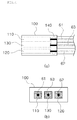
- FIG. 4 is a plan view (a) and front view (b) of a first connector 100 which is one element of the power supply apparatus for an LED light according to an embodiment of the present invention.
- the power supply apparatus for an LED light may further include the first connector 100.
- the first connector 100 may include a coupling unit 140 to which the other ends of the first to the third wires 61, 62, and 63 are coupled and first to third guide grooves 110, 120, and 130 into which the pins 210 and 220 of the second connector 200 are inserted.
- the coupling unit 140 is configured to surround some of the other ends of the first to the third wires 61, 62, and 63 at the same time, and functions to fix the other ends of the first to the third wires 61, 62, and 63.
- the coupling unit 140 may have a form that directly surrounds the first to the third wires 61, 62, and 63, but is not limited thereto.
- the coupling unit 140 may have a form that surrounds coating to surround the first to the third wires 61, 62, and 63.
- the first to the third guide grooves 110, 120, and 130 may have a form into which the pins 210 and 220 of the second connector 200 may be inserted and engaged.
- the first to the third guide grooves 110, 120, and 130 may be connected to the other ends of the first to the third wires 61, 62, and 63, respectively, as shown in FIG. 4 .
- the pin 210, 220 of the second connector 200 may be electrically connected to at least any one of the other ends of the first to the third wires 61, 62, and 63.
- FIG. 5 is a front view and plan view of the second connector 200 which is one element of the power supply apparatus for an LED light according to an embodiment of the present invention.
- the second connector 200 which is connected to the first connector 100 and changes a voltage applied across the second resistor R2 according to the resistance composition principle and the voltage distribution principle may include a first pin 210 and a second pin 220.
- first pin 210 and the second pin 220 may have been electrically connected.
- first pin 210 and the second pin 220 form combined resistance by electrically connecting the other end of the third wire 63 to the other end of any one of the first wire 61 and the second wire 62.
- a driving voltage applied to the driving voltage port VIN is 5 V (volts)
- each of the first to the third resistors R3 has 10 kO
- the second pin 220 has been inserted into the first guide groove 110 in the state in which the first pin 210 has been inserted into the third guide groove 130.
- the first resistor R1 and the third resistor R3 become a parallel connection state and have combined resistance of 5 kO.
- About 3.33 V is applied across the second resistor R2 connected to the first resistor R1 and the third resistor R3 in series.
- the second resistor R2 and the third resistor R3 become a parallel connection state and have combined resistance of 5 kO.
- the driving voltage of 5 V is divided by the first resistor R1 of 10 kO and the combined resistance of 5 kO, and thus about 1.67 V is applied across the second resistor R2.
- the MCU 30 may detect a changed voltage across the second resistor through the voltage sensing port VSENSE, and may select or adjust the amount of an electric current supplied to the LED light side.
- FIG. 6 is a front view of the first connector 100 and the second connector 200 which are elements of the power supply apparatus for an LED light according to an embodiment of the present invention.
- At least one corner of the first connector 100 may be bent or protruded in response to a shape of the body of the second connector 200.
- at least one corner of the first to the third guide grooves 110, 120, and 130 may be bent or protruded in response to a shape of the pins 210 and 220 of the second connector 200.
- the first connector 100 and the second connector 200 are accurately engaged. Accordingly, a problem in that an unwanted current is supplied to an LED light or a short is generated because the second connector 200 is inserted in a wrong direction can be prevented.
- FIG. 7 is a plan view of a power supply apparatus for an LED light according to an embodiment of the present invention
- FIG. 8 is a plan view of a second connector which is one element of the power supply apparatus for an LED light according to an embodiment of the present invention.
- the third wire 63 does not include the third resistor R3. That is, the third wire 63 may have one end connected to the voltage sensing node 40 and may have the other end open and coupled to the first connector 100.
- the second connector 200 may further include the third resistor R3 in addition to the first pin 210 and the second pin 220.
- the first pin 210 and the second pin 220 may be connected to both ends of the third resistor R3. That is, the first pin 210 is electrically connected to the second pin 220 through the third resistor R3.
- a driving voltage applied to the driving voltage port VIN is 5 V (volts)
- each of the first to third resistors R3 is 10 kO
- the second pin 220 has been inserted into the first guide groove 110 in the state in which the first pin 210 has been inserted into the third guide groove 130.
- the first resistor R1 and the third resistor R3 become a parallel connection state and have combined resistance of 5 kO.
- About 3.33 V is applied across the second resistor R2 connected to the first resistor R1 and the third resistor R3 in series in accordance with the voltage distribution principle.
- the second resistor R2 and the third resistor R3 become a parallel connection state and have combined resistance of 5 kO.
- the driving voltage of 5 V is divided by the first resistor R1 of 10 kO and the combined resistance of 5 kO, and thus about 1.67 V is applied across the second resistor R2.
- first pin 210 and the second pin 220 may form combined resistance by electrically connecting the other end of the third wire 63 to the other end of any one of the first wire 61 and the second wire 62.
- FIG. 9 is a perspective view of a power supply apparatus for an LED light having an improved insulating property according to an embodiment of the present invention
- FIG. 10 is a perspective view of the power supply apparatus for an LED light having an improved insulating property according to an embodiment of the present invention.
- the power supply apparatus for an LED light having an improved insulating property includes a printed circuit board 310, a housing 320, and a power wire 3100.
- the power wire 3100 has one end connected to the printed circuit board 310 and the other end connected to an external power source or an LED light. That is, in accordance with an embodiment of the present invention, the power wire 3100 may be used for input and output.
- the input power wire 3100 and the output power wire 3100 may be the same. Accordingly, the input power wire 3100 is chiefly described below.
- the printed circuit board 310 means a thin plate which is electrically connected to a circuit 311 by soldering, etc. and to which the circuit 311 is fixed.
- the circuit 311 converts input power, supplied by the power wire 3100, into output power for driving an external LED light.
- the circuit 311 of a constant current type power supply apparatus may convert an AC into a DC.
- the circuit 311 may be configured to include a diode, an EMI filter, a capacitor, an inductor, a register, an integrated circuit 311 (IC), a heat sink, a transistor, an operation amplifier, etc.
- One side of the printed circuit board 310 is commonly used, but the present invention is not limited thereto. Both sides of the printed circuit board 310 may be used.
- the housing 320 is a term indicative of a box-shaped member that surrounds various parts or mechanical devices.
- the printed circuit board 310 is mounted on the internal space of the housing 320, and the housing 320 functions to shield the printed circuit board 310 from the outside.
- a silicon molding solution may be coated on the inside of the housing 320. The silicon molding solution functions to uniformly distribute heat, generated in a process of converting, by the circuit 311, power, to the internal space of the housing 320.
- an opening portion through which the other end of the power wire 3100 passes and which is drawn to the outside of the housing 3320 is provided on one side of the housing 320.
- the power wire 3100 includes a dual insulation unit 3120 and a power supply conductor 3110.
- the power supply conductor 3110 may be connected to an external power source directly or through another conductor. Furthermore, the power supply conductor 3110 is isolated from the outside by the dual insulation unit 3120. That is, the dual insulation unit 3120 has a form that surrounds a middle end portion other than some region of both ends of the power supply conductor 3110 in a length direction.
- the dual insulation unit 3120 includes first insulating means 3121 and second insulating means 3122.
- the first insulating means 3121 is made of a first insulating material 3123 and is configured to surround the power supply conductor 3110.
- the second insulating means 3122 is made of a second insulating material 3124 and is configured to surround the first insulating means 3121. That is, the power supply conductor 3110 may be covered with the first insulating means 3121, and the first insulating means 3121 may be covered with the second insulating means 3122. Such covering may be performed by an extrusion molding method.
- the first insulating material 3123 and the second insulating material 3124 may include one or a combination of two or more of insulating materials, such as polyethylene resin, crosslinked polyethylene, polybuthylene terephthanlate, crosslinked polyolefin, a thermoplastic polyester copolymer, ethylene propylene rubber, co-poly (ether-ester) resin, co-poly (ester-ester) resin, PVC, a silicon-series compound, and polypropylene.
- insulating materials such as polyethylene resin, crosslinked polyethylene, polybuthylene terephthanlate, crosslinked polyolefin, a thermoplastic polyester copolymer, ethylene propylene rubber, co-poly (ether-ester) resin, co-poly (ester-ester) resin, PVC, a silicon-series compound, and polypropylene.
- first insulating material 3123 and the second insulating material 3124 may be made of the same material or different materials.
- the first insulating material 3123 and the second insulating material 3124 are made of different materials, the first insulating means 3121 and the second insulating means 3122 are not united, but come in contact with each other in the separate state due to a difference between the physical properties of the first and the second insulating materials. Accordingly, there is an advantage in that the second insulating means 3122 can be easily peeled off from the first insulating means 3121 when a task for connecting the end of the power wire 3100 to an external power source or an LED light is performed.
- the power supply apparatus for an LED light having an improved insulating property may further include a gasket 330.
- the gasket 330 may be coupled to the circumference of the second insulating means 3122, as shown in FIGS. 9 and 10 .
- the gasket 330 is means inserted so that gas or water does not leak from a contact surface between two fixed parts.
- the gasket 330 shields the space between the power wire 3100 and an opening portion.
- the gasket 330 may be made of PVC.
- the gasket 330 may have a relative temperature index (RTI) of 90°C or more.
- the relative temperature index (RTI) is an evaluation index for a long-term heat-resistant temperature of plastic.
- RTI 90°C means that physical properties measured after a use for continuous 60,000 hours at a temperature of 90°C maintain 50% of the first physical properties.
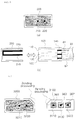
- FIG. 11 is a diagram showing the state in which the power wire 3100 and the gasket 330 have been coupled together according to an embodiment of the present invention.
- the gasket 330 may include a fitting groove 331 corresponding to a shape of the opening portion, as shown in FIGS. 10 and 11 .
- the fitting groove 331 is combined with the shape of the opening portion, and the body of the gasket 330 closely adheres to a designated area of the inner surface and outer surface of the housing 320 on the circumference of the opening portion.
- the lifespan of the power supply apparatus can be extended because rainwater or dust is prevented from permeating into the housing 320 although the power supply apparatus is installed outdoors.
- the gasket 330 can also prevent the silicon molding solution coated on the inside of the housing 320 from leaking to the outside of the housing 320.
- the gasket 330 may further include reinforcement means 332.
- the reinforcement means 332 is an element for increasing a friction force between the power wire 3100 and the gasket 330. Accordingly, the reinforcement means 332 can prevent a physical impact from being applied to the circuit 311 because the power wire 3100 and the gasket 330 are decoupled by an external force, etc.
- the reinforcement means 332 may be connected to one side of the gasket 330 placed within the housing 320 when the gasket 330 and the housing 320 are coupled. Furthermore, the reinforcement means 332 may have a shape that surrounds the second insulating means 3122 in the length direction of the power wire 3100 (i.e., the direction directed from one end to the other end).
- a portion at which the gasket 330 and the second insulating means 3122 are coupled may be designed so that a friction force opposing 5 kgf (kilogram-force) for 1 hour or more at 100°C is generated at the portion.
- FIG. 12 is a diagram showing that the power wire 3100 having the gasket 330 coupled thereto may be easily bent by a mobility groove 333 in accordance with an embodiment of the present invention.
- the reinforcement means 332 may be equipped with the mobility groove 333.
- the mobility groove 333 is an element for facilitating bending (i.e., increasing the bending range) without applying damage to the power supply conductor 3110, the first insulating means 3121, or the second insulating means 3122 included in the power wire 3100.
- the width of the entire power wire 3100 dually insulated by the first insulating means 3121 and the second insulating means 3122 is widened.
- the range that the power wire 3100 is bent is limited and the power wire 3100 may be broken if an external force is intentionally applied to the power wire 3100.
- the mobility groove 333 is included in the reinforcement means 332, the mobility of the power wire 3100 can be increased and connection easiness with the circuit 311 when the power supply apparatus is fabricated is increased, thereby being capable of improving production efficiency.
- FIG. 13 is a perspective view of a power supply apparatus for an LED light according to an embodiment of the present invention.
- the power supply apparatus for an LED light includes a circuit 510, a printed circuit board 5100, an MCU 5200, a connector 5300, and a housing 5400.
- the circuit 510 means a circuit which converts input power into output power for driving an LED light.
- a diode for example, a diode, an EMI filter, a capacitor, an inductor, a register, an integrated circuit (IC), a heat sink, a transistor, an operation amplifier, etc. may be included in the circuit 510.
- a diode for example, a diode, an EMI filter, a capacitor, an inductor, a register, an integrated circuit (IC), a heat sink, a transistor, an operation amplifier, etc.
- the printed circuit board 5100 means a thin plate which is electrically connected to the circuit 510 by soldering, etc. and to which the circuit 510 is thus fixed.
- One side of the printed circuit board 5100 is commonly used, but the present invention is not limited thereto. Both sides of the printed circuit board 5100 may be used, if necessary.
- the micro controller unit (MCU) 5200 is an element that plays the role of the brain of an electronic product, and is a term meaning a non-memory semiconductor part which controls various functions from a simple time schedule to a special function.
- a program for outputting a control signal for an LED light is recorded on the MCU 5200, and the MCU 5200 is connected to the printed circuit board 5100.
- control signal output in accordance with the recorded program is transferred to the circuit 510 through the printed circuit board 5100 so that a target function is implemented.
- the connector 5300 may be connected to an external terminal, and is an element which transfers a program conversion signal received from the external terminal to the MCU 5200.
- the connector 5300 functions to relay data between the external terminal and the MCU 5200.
- the external terminal may be a DALI interface which is connected to a terminal device, such as a specific user's PC, and supports DALI communication.
- the connector 5300 has one side connected to the external terminal and the other side connected to the MCU 5200.
- the other side may be directly connected to the MCU 5200 or may be connected to the MCU 5200 via the pattern of the printed circuit board 5100 or the circuit 510.
- the housing 5400 is a term indicative of a box-shaped member that surrounds various parts or mechanical devices.
- the housing 5400 may accommodate the printed circuit board 5100, the MCU 5200, and the connector.
- the printed circuit board 5100, the MCU 5200, and the connector may be mounted on the bottom surface of the housing 5400, but the present invention is not limited thereto. They may be mounted on any place within the space provided by the housing 5400.
- top surface, bottom surface, and side of the housing 5400 may be combined in the state in which the housing has been separated into the top surface, bottom surface, and side, or the housing 5400 may be an integration type.
- an opening portion 5410 may be provided on one side of the housing 5400.
- the opening portion 5410 is an element for the connection of an external terminal and the connector 5300.
- FIG. 14 is a perspective view of the connector 5300 included in the power supply apparatus for an LED light according to an embodiment of the present invention.
- the connector 5300 included in the power supply apparatus for an LED light may include a plurality of connector pins 5310.
- Each of the plurality of connector pins 5310 included in the connector 5300 may be subjected to bending processing, as shown in FIG. 14 .
- a ratio of the length from such a bending-processed area to one side and the other side may be 2:1, for example, but is not limited thereto.
- the connector pins 5310 are subjected to bending processing, one sides of the connector pins 5310 can be placed in parallel to the bottom surface of the housing 5400 and exposed through the opening portion 5410 when the connector 5300 is fully mounted on the inside of the housing 5400 of the power supply apparatus. Accordingly, there is an advantage in that a connection with an external terminal is facilitated.
- the connector 5300 may further include pin support means 5320.
- the pin support means 5320 is an element for preventing deformation of the plurality of connector pins 5310, such as curve or bending attributable to an external impact, etc. by supporting each of the plurality of connector pins 5310.
- the pin support means 5320 can prevent the generation of a data transmission error or a short by blocking a contact between the connector pins 5310.
- the pin support means 5320 includes a plurality of through holes 5321 spaced apart from each other at a designated interval.
- the through hole 5321 means a hole that penetrates one side and the other side of the pin support means 5320 in the length direction.
- the through hole 5321 may be a circle, but is not limited thereto.
- the through hole 5321 may have a shape capable of supporting the connector pin 5310 when the connector pin 5310 is inserted into the through hole 5321.
- the number of through holes 5321 may be the same as or greater than the number of connector pins 5310.
- some area between one side and the other side of each of the connector pins 5310 may be coupled to and surrounded by the inside of the through hole 5321 by the length d of the pin support means 5320.
- One side and the other side of each of the connector pins 5310 may be protruded to the outside of the through hole 5321.
- one side of the connector pin 5310 protruded to the outside of the through hole 5321 may be connected to an external terminal, and the other side thereof may be connected the printed circuit board 5100, the circuit 510, or the MCU 5200.
- the plurality of connector pins 5310 may be first to fifth connector pins 5310.
- the first connector pin 5310 connected from an external terminal connected to the connector 5300 may receive information about an operating frequency.
- the second connector pin 5310 may receive a program conversion signal synchronized with the operating frequency received through the first connector pin 5310.
- the third connector pin 5310 may ground the external terminal and the MCU 5200.
- the fourth connector pin 5310 may supply power to the external terminal.
- the fifth connector pin 5310 may receive a reset command for information recorded on the MCU 5200.
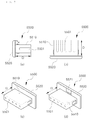
- FIG. 15 is a side view of the power supply apparatus for an LED light according to an embodiment of the present invention
- FIG. 16 is a front view of the power supply apparatus for an LED light according to an embodiment of the present invention.
- the power supply apparatus for an LED light in which the printed circuit board 5100, the circuit 510, the MCU 5200, and the connector 5300 have been mounted on the inside of the housing 5400 in accordance with an embodiment of the present invention may be checked.
- the connector pins 5310 are subjected to bending processing, and one side of each of the connector pins 5310 is placed in parallel to the bottom surface of the housing 5400 and thus exposed through the opening portion 5410.
- FIG. 15 illustrates that the other side of each of the connector pins 5310 has been directly connected to the printed circuit board 5100, but is not limited thereto.
- the other side of the connector pin 5310 may be interpreted as being connected to the MCU 5200 or the circuit 510.
- FIG. 17 is a side view, front view, and perspective view of a gasket 5500 included in the power supply apparatus for an LED light according to an embodiment of the present invention
- FIG. 18 is a side view of a power supply apparatus for an LED light according to another embodiment of the present invention.
- the gasket 5500 refers to means inserted in order to prevent gas or water from leaking from a contact surface between two fixed parts.
- the gasket 5500 includes a body 5510 and insertion grooves 5501.
- the number of insertion grooves 5501 may be the same as or greater than the number of connector pins 5310.
- the length D of the body 5510 of the gasket 5500 may be the length or more of one side of the connector pin 5310 inserted into the insertion groove 5501.
- the insertion grooves 5501 are spaced apart from each other at the same interval as that between the through holes 5321 of the pin support means 5320.
- gasket 5500 may further include packing means 5520 extended in a direction orthogonal to the length direction of the body 5510 by a designated length "a" from the outer circumference of the other end of the body 5510.
- a separation groove 5521 may be provided in the packing means 5520. More specifically, the separation groove 5521 is a groove having a length shorter than "a" provided at the edge of the packing means 5520. There is an advantage that the gasket 5500 and the connector can be easily attached and detached through the separation groove 5521.
- the gasket 5500 may be connected to the connector 5300, one side of each of the connector pins 5310 is inserted into each of the insertion grooves 5501 of the gasket 5500, and thus the packing means 5520 of the gasket 5500 may closely adhere to a designated area in the circumference of the opening portion 5410 on the outside of the housing 5400.
- the materials of the gasket 5500 may include silicon-series compounds, such as methyl hydrodien silicon, polydimethyl siloxane diol, epoxy-modified silicon oil, carboxyl-modified silicon, methacryl-modified silicon oil, alcohol-modified silicon, mercapto-modified silicon, vinyl-modified silicon, and amino-modified silicon.
- silicon-series compounds such as methyl hydrodien silicon, polydimethyl siloxane diol, epoxy-modified silicon oil, carboxyl-modified silicon, methacryl-modified silicon oil, alcohol-modified silicon, mercapto-modified silicon, vinyl-modified silicon, and amino-modified silicon.
- the gasket 5500 can prevent deformation of the connector pins 5310 along with the pin support means 5320.
- the lifespan of the power supply apparatus can be extended by preventing rainwater or dust from permeating into the housing 5400 through the opening portion 5410 of the housing 5400.
- waste and inconvenience in which the power supply apparatus must be replaced when an LED light is replaced can be solved.
- the same performance as that obtained when the power supply apparatus is replaced can be obtained by connecting a separate resistor and changing impedance of the voltage sensing resistor (RSET) through a simple manipulation, and thus light management efficiency can be increased because a cost is minimized.
- RSET voltage sensing resistor
- a user can easily change an output current of the power supply apparatus through a simple manipulation for exposing the connector connected to the voltage sensing resistor (RSET) of the power supply apparatus to the outside and inserting an external connector into the connector.
- RSET voltage sensing resistor
- a short attributable to the erroneous connection of an external connector can be prevented by designing an external shape so that the connector of the power supply apparatus and the external connector are engaged.
- deterioration or aging attributable to moisture or an external impact can be prevented and a danger of an electric shock can be reduced by dually insulating the power wire included in the power supply apparatus for an LED light.
- the penetration of moisture or dust into the housing can be prevented and the leakage of a molding solution coated on the inside of the housing can be blocked by shielding the space between the power wire and the housing through the gasket.
- the grooves are provided in some region of the gasket coupled to the power wire, the mobility of the power wire having a widened width through dual insulation can be improved, and the connection of the power wire and the circuit can be easily connected when the power supply apparatus is fabricated.
- digital control complying with different needs of users can be implemented because a program for outputting a digital control signal is recorded on the MCU connected to the printed circuit board mounted on the power supply apparatus.
- a program recorded on the MCU can be freely changed by mounting the connector connected to the MCU on the power supply apparatus, opening one side of the housing so that the connector is exposed, and connecting an external terminal to the connector.
- Parts of the power supply apparatus can be protected against an external environment, such as rainwater and dust, and the lifespan of the power supply apparatus can be extended because the gasket is inserted from the outside of the housing and the gasket is connected to the connector.
Landscapes
- Engineering & Computer Science (AREA)
- General Engineering & Computer Science (AREA)
- Power Engineering (AREA)
- Arrangement Of Elements, Cooling, Sealing, Or The Like Of Lighting Devices (AREA)
- Details Of Connecting Devices For Male And Female Coupling (AREA)
- Non-Portable Lighting Devices Or Systems Thereof (AREA)
Abstract
Description
- The present invention relates to an apparatus for supplying power to an LED light.
- As society gradually evolves, the light industry requires various functions, such as individual and group control. Furthermore, as an environmental problem becomes serious, there is an increasing need for a light capable of reducing energy.
- Accordingly, after a light-emitting diode (hereinafter referred to as an "LED") which is eco-friendly and has high energy efficiency was developed, there is a tendency that LED-related technologies become high efficiency very rapidly due to technology competitiveness, are spread into common light and high efficiency light markets due to the development of a white LED, continue to replace existing lights.
- An LED driving circuit may implement various circuits depending on a design object. In this case, the LED driving circuit has a strong influence on efficiency of a driving circuit and the lifespan of an LED depending on uses, the driving characteristic of an LED, and the configuration of an LED array.
- Meanwhile, in order to drive such an LED light, a power supply apparatus is commonly connected.
- The power supply apparatus functions to receive external power and to convert the external power into power for driving the LED light. For example, a constant current type power supply apparatus converts an AC applied thereto into a direct current (DC) and supplies the DC to an LED light, that is, a light source.
- As the range of use of an LED light is widened, a power supply apparatus for driving the LED light is designed in various ways from several tens of watts (W) to several hundreds of watts (W). To secure insulation with the outside becomes more important because a danger of an electric shock is increased as the capacity is increased.
- Furthermore, as people's interest in lights recently gradually increases along with the improvement of quality of life, a current light device requires more than it turns on a light using a switch. That is, a current light device is developing into a more advanced form, such as producing various atmospheres depending on indoor uses or automatically adjusting luminous intensity properly depending on surrounding luminous intensity. A light device that evolves as described above is internationally used based on digital addressable lighting interface (DALI) communication.
- An object of the present invention is to solve waste and inconvenience in which a power supply apparatus must be replaced when an LED light is replaced.
- An object of the present invention is to show the same performance as that obtained when a power supply apparatus is replaced by connecting a separate resistor and changing impedance of a voltage sensing resistor (RSET) through a simple manipulation and to increase light management efficiency by minimizing a cost.
- An object of the present invention is to enable a user to easily change an output current of a power supply apparatus through a simple manipulation in which a connector connected to the voltage sensing resistor (RSET) of the power supply apparatus is exposed to the outside and an external connector is inserted into the connector.
- An object of the present invention is to prevent a short attributable to the erroneous connection of an external connector by designing an external shape so that the connector of a power supply apparatus and the external connector are engaged.
- An object of the present invention is to prevent deterioration or aging attributable to moisture or an external impact and to reduce a danger of an electric shock by dually insulating a power wire included in a power supply apparatus for an LED light.
- An object of the present invention is to prevent the penetration of moisture or dust into a housing and to block the leakage of a molding solution coated on the inside of the housing by shielding the space between a power wire and the housing through a gasket.
- An object of the present invention is to improve the mobility of a power wire having a widened width through dual insulation by providing grooves in some region of a gasket coupled to the power wire, thereby facilitating the connection of the power wire and a circuit when a power supply apparatus is fabricated.
- An object of the present invention is to implement digital control complying with different needs of users because a program for outputting a digital control signal is recorded on an MCU connected to a printed circuit board mounted on a power supply apparatus.
- An object of the present invention is to freely change a program recorded on an MCU by mounting a connector connected to the MCU on a power supply apparatus, opening part of a housing so that the connector is exposed, and connecting an external terminal to the connector.
- An object of the present invention is to protect parts of a power supply apparatus against an external environment, such as rainwater and dust, and to extend the lifespan of the power supply apparatus by inserting a gasket from the outside of a housing and connecting the gasket to a connector.
- In accordance with an aspect of the present invention, there is provided a power supply apparatus for an LED light, including a printed circuit board on which a circuit converting input power into output power for driving an LED light has been printed, an MCU which includes a driving voltage port, a ground port, and a voltage sensing port, which is connected to the printed circuit board, and which transfers a control signal for converting an electric current applied to the LED light to the circuit based on a voltage inputted to the voltage sensing port, a first resistor which has one end connected to the driving voltage port and has the other end connected to the voltage sensing node, a second resistor which has one end connected to the ground port and has the other end connected to the voltage sensing node, a sensing wire which has one end connected to the voltage sensing port and has the other end connected to the voltage sensing node, a first wire which has one end connected to the one end of the first resistor and has the other end open, a second wire which has one end connected to the one end of the second resistor and has the other end open, a third wire which includes a third resistor, wherein the third resistor has one end connected to the voltage sensing node and has the other end open, and a housing on which the printed circuit board, the MCU, the first resistor, the second resistor, the third resistor, and the sensing wire are mounted in the internal space of the housing.
- Furthermore, an opening portion may be provided on one side of the housing, and the other ends of the first to the third wires may be extended to the outside of the housing through the opening portion.
- Furthermore, the power supply apparatus may further include a gasket which is coupled to the stop portions of the first to the third wires and closely adheres to a designated area of the outer surface and inner surface of the opening portion.
- Furthermore, the power supply apparatus may further include a first connector including a coupling unit to which the other ends of the first to the third wires are coupled and first to third guide grooves into which the pins of a second connector are inserted. The first to the third guide grooves may be extended up to the other ends of the first to the third wires, respectively.
- Furthermore, at least one corner of the body of the first connector may be bent or protruded in response to a shape of the body of the second connector or at least one corner of the guide groove may be bent or protruded in response to a shape of the pin of the second connector so that an erroneous connection of the second connector is blocked.
- Furthermore, the second connector includes first and second pins coupled together. The first pin may be inserted into the third guide groove, and the second pin may be inserted into any one of the first and the second guide grooves.
- Furthermore, the first and the second pins may electrically connect the other end of the third wire to the other end of any one of the first wire and the second wire.
- In accordance with another aspect of the present invention, there is provided a power supply apparatus for an LED light, including a printed circuit board on which a circuit converting input power into output power for driving an LED light has been printed, an MCU which includes a driving voltage port, a ground port, and a voltage sensing port, which is connected to the printed circuit board, and which transfers a control signal for converting an electric current applied to the LED light to the circuit based on a voltage inputted to the voltage sensing port, a first resistor which has one end connected to the driving voltage port and has the other end connected to the voltage sensing node, a second resistor which has one end connected to the ground port and has the other end connected to the voltage sensing node, a sensing wire which has one end connected to the voltage sensing port and has the other end connected to the voltage sensing node, a first wire which has one end connected to the one end of the first resistor and has the other end open, a second wire which has one end connected to the one end of the second resistor and has the other end open, a third wire which has one end connected to the voltage sensing node and has the other end open, and a housing on which the printed circuit board, the MCU, the first resistor, the second resistor, the third resistor, and the sensing wire may be mounted in an internal space of the housing.
- Furthermore, the power supply apparatus may further include a first connector including a coupling unit to which the other ends of the first to the third wires are coupled and first to third guide grooves into which the pins of a second connector are inserted. The first to the third guide grooves may be connected to the other ends of the first to the third wires, respectively. The second connector may include a third resistor and first and second pins connected to both ends of the third resistor. The first pin may be inserted into the third guide groove. The second pin may be inserted into any one of the first and the second guide grooves.
- Furthermore, the first and the second pins may electrically connect the other end of the third wire to the other end of any one of the first wire and the second wire.
- In accordance with an aspect of the present invention, there is provided a power supply apparatus for an LED light having improved insulation performance, including a power wire which has one end connected to a printed circuit board, a printed circuit board on which a circuit for converting input power supplied by the power wire into output power for driving an exterior LED light has been printed, and a housing which accommodates the printed circuit board and includes an opening portion through which the other end of the power wire passes and which is drawn to the outside of the housing. The power wire includes a dual insulation unit and a power supply conductor connected to an external power source and isolated from the outside by the dual insulation unit.
- Furthermore, the dual insulation unit may include first insulating means which is made of a first insulating material and surrounds the power supply conductor and second insulating means which is made of a second insulating material and surrounds the first insulating means.
- Furthermore, the power supply apparatus may further include a gasket which is coupled to the circumference of the second insulating means and includes a fitting groove inserted into the edge of the opening portion. Furthermore, the gasket may further include reinforcement means which is connected to one of both sides of the gasket and surrounds the second insulating means in the length direction of the power wire. Furthermore, the reinforcement means may include a mobility groove for facilitating a bending of the power wire. Furthermore, the gasket may be made of PVC having a relative temperature index (RTI) of 90°C. Furthermore, a friction force corresponding to 5 kgf (kilogram-force) for 1 hour or more at 100°C may be generated at a portion where the gasket and the second insulating means are coupled.
- In accordance with an aspect of the present invention, there is provided a power supply apparatus for an LED light, including a printed circuit board on which a circuit converting input power into output power for driving an LED light has been printed, an MCU on which a program outputting a control signal for the LED light is recorded, which is connected to the printed circuit board, and which transfers the control signal to the circuit, a connector which has one side connected to an external terminal, has the other side connected to the MCU, and transfers a program conversion signal received from the external terminal to the MCU, and a housing which accommodates the printed circuit board, the MCU, and the connector and has an opening portion for connecting the external terminal and the connector on one side of the housing.
- The connector may include a plurality of connector pins. A designated area between one side and the other side of the plurality of connector pins may have been subjected to bending processing. The connector may further include pin support means including a plurality of through holes spaced apart from each other at a designated interval. The number of through holes may be identical with the number of connector pins. Each of the connector pins may be coupled to the inside of each of the through holes, and one side and the other side of each of the connector pins may be protruded to the outside of the through hole. The power supply apparatus may further include a gasket including a body and a plurality of insertion grooves spaced apart from each other at an interval identical with the designated interval at one end of the body. The number of insertion grooves may be identical with the number of connector pins. The gasket may further include packing means extended from the other end of the body in a direction orthogonal to the length direction of the body. A separation groove may be provided on the inside of the packing means. The gasket may be made of a silicon-series compound. The connector may include first to fifth connector pins connected to the external terminal. The first connector pin may receive information about an operating frequency. The second connector pin may receive a program conversion signal synchronized with the operating frequency. The third connector pin may ground the external terminal and the MCU. The fourth connector pin may supply power to the external terminal. The fifth connector pin may receive a reset command for information recorded on the MCU.
-
-
FIG. 1 is a plan view of a power supply apparatus for an LED light according to an embodiment of the present invention. -
FIG. 2 is a perspective view of the power supply apparatus for an LED light according to an embodiment of the present invention. -
FIG. 3 is a perspective view of the power supply apparatus for an LED light according to an embodiment of the present invention. -
FIG. 4 is a plan view and front view of a first connector which is one element of the power supply apparatus for an LED light according to an embodiment of the present invention. -
FIG. 5 is a front view and plan view of a second connector which is one element of the power supply apparatus for an LED light according to an embodiment of the present invention. -
FIG. 6 is a front view of the first connector and the second connector which are elements of the power supply apparatus for an LED light according to an embodiment of the present invention. -
FIG. 7 is a plan view of a power supply apparatus for an LED light according to an embodiment of the present invention. -
FIG. 8 is a plan view of a second connector which is one element of the power supply apparatus for an LED light according to an embodiment of the present invention. -
FIG. 9 is a perspective view of a power supply apparatus for an LED light having an improved insulating property according to an embodiment of the present invention. -
FIG. 10 is a perspective view of the power supply apparatus for an LED light having an improved insulating property according to an embodiment of the present invention. -
FIG. 11 is a diagram showing the state in which a power wire and a gasket have been coupled together according to an embodiment of the present invention. -
FIG. 12 is a diagram showing that the power wire having the gasket coupled thereto may be easily bent by a mobility groove in accordance with an embodiment of the present invention. -
FIG. 13 is a perspective view of a power supply apparatus for an LED light according to an embodiment of the present invention. -
FIG. 14 is a perspective view of connectors included in the power supply apparatus for an LED light according to an embodiment of the present invention. -
FIG. 15 is a side view of the power supply apparatus for an LED light according to an embodiment of the present invention. -
FIG. 16 is a front view of the power supply apparatus for an LED light according to an embodiment of the present invention. -
FIG. 17 is a side view, front view, and perspective view of a gasket included in the power supply apparatus for an LED light according to an embodiment of the present invention. -
FIG. 18 is a side view of a power supply apparatus for an LED light according to another embodiment of the present invention. - Embodiments disclosed in this specification should not be interpreted as limiting or used to limit the scope of the present invention. It is evident to those skilled in the art that a description including the embodiments of this specification has various applications. Accordingly, unless otherwise defined by the claims, some embodiments described are illustrative for better understanding, and the scope of the present invention is not intended to be restricted by the embodiments. Furthermore, in describing the present invention, a detailed description of the known functions or constitutions will be omitted if it is deemed to make the gist of the present invention unnecessarily vague.
- Hereinafter, embodiments of the present invention are described in more detail with reference to the accompanying drawings.
-
FIG. 1 is a plan view of a power supply apparatus for an LED light according to an embodiment of the present invention. - Referring to
FIG. 1 , the power supply apparatus for an LED light according to an embodiment of the present invention includes a printedcircuit board 20, a microcontroller unit (MCU) 30, a first resistor R1, a second resistor R2, asensing wire 64, afirst wire 61, asecond wire 62, athird wire 63, and ahousing 50. - First, a
circuit 10 means a circuit for converting external power into output power for driving an LED light connected to the power supply apparatus. - For example, a diode, an EMI filter, a capacitor, an inductor, a register, an integrated circuit (IC), a heat sink, a transistor, an operation amplifier, etc. may be included in the circuit.
- The printed
circuit board 20 means a thin plate which is electrically connected to thecircuit 10 by soldering, etc. and to which thecircuit 10 is fixed. - One side of the printed
circuit board 20 is commonly used, but the present invention is not limited thereto. Both sides of the printedcircuit board 20 may be used, if necessary. - The
MCU 30 is a term meaning a non-memory semiconductor part which is responsible for the brain of an electronic product and controls various functions from a simple time schedule to a specific function. In the present invention, a program for outputting a control signal for an LED light is recorded on theMCU 30, and theMCU 30 is connected to the printedcircuit board 20. - In particular, the
MCU 30 includes a driving voltage port VIN, a voltage sensing port VSENSE, and a ground port GND. A driving voltage for driving theMCU 30 is applied to the driving voltage port VIN. Voltages that belong to the driving voltage applied to the driving voltage port VIN and that are divided by the first to the third resistors R3 are sensed at the voltage sensing port VSENSE. TheMCU 30 is grounded through the ground port GND. - That is, the
MCU 30 generates a control signal in accordance with a program for converting an electric current applied to the LED light based on a voltage inputted to the voltage sensing port VSENSE and transfers the control signal to thecircuit 10. - For example, the MCU may generate a control signal which performs control so that an electric current of 700 mA is output when a voltage A is inputted to the voltage sensing port VSENSE, which performs control so that an electric current of 530 mA is output when a voltage B is inputted to the voltage sensing port VSENSE, and which performs control so that an electric current of 350 mA is output when a voltage C is inputted to the voltage sensing port VSENSE, and may transfer the generated control signal to the
circuit 10. - A process in which a voltage applied to the voltage sensing port VSENSE is changed by the first to the third resistors R3 is described in more detail below.
- The first resistor R1 and the second resistor R2 are elements which are basically included in order to divide a driving voltage.
- Referring to
FIG. 1 , the first resistor R1 has one end connected to the driving voltage port VIN and the other end connected to avoltage sensing node 40. The second resistor R2 has one end connected to the ground port GND and the other end connected to thevoltage sensing node 40. That is, in this case, the second resistor R2 functions as a voltage sensing resistor (RSET). Furthermore, thevoltage sensing node 40 is a node at which the other ends of the first resistor R1 and the second resistor R2 are coupled together, and is connected to the voltage sensing port VSENSE through thesensing wire 64. - For example, it is assumed that a driving voltage applied to the driving voltage port VIN is 5 V (volts) and the first and the second resistors R1 and R2 are 10 kO (kilo-ohm). 2.5 V of the driving voltage is distributed to the other end of each of the first and the second resistors R1 and R2 according to the voltage distribution principle. The voltage sensing port VSENSE may detect 2.5 V applied across the second resistor R2.
- The
first wire 61 has one end connected to one terminal of the first resistor R1. Thesecond wire 62 has one end connected to one end of the second resistor R2. Thethird wire 63 has one end connected to thevoltage sensing node 40. Furthermore, thethird wire 63 includes a third resistor R3 between one end and the other end. All of the other ends of the first to thethird wires - If the other ends of the first to the
third wires 63 are open, the third resistor R3 included in thethird wire 63 does not generate combined resistance along with the first resistor R1 and the second resistor R2. In contrast, if an external connector is connected, any two of the other ends of the first to thethird wires - In general, the
housing 50 is a term indicative of a box-shaped member that surrounds various parts or mechanical devices. In the present invention, the printedcircuit board 20, theMCU 30, the first resistor R1, the second resistor R2, and one ends of thesensing wire 64 and the first to thethird wires housing 50. - Furthermore, as shown in
FIG. 1 , the printedcircuit board 20, theMCU 30, the first resistor R1, the second resistor R2, and one ends of thesensing wire 64 and the first to thethird wires housing 50, but the present invention is not limited thereto. They may be mounted on any place of the internal space of thehousing 50. - Furthermore, the top surface, bottom surface, and side of the
housing 50 may be combined in the state in which the housing has been separated into the top surface, the bottom surface, and the side, or thehousing 50 may be an integration type. -
FIGS. 2 and3 are perspective views of the power supply apparatus for an LED light according to an embodiment of the present invention. - Referring to
FIG. 2 , the power supply apparatus for an LED light according to an embodiment of the present invention may include anopening portion 51 on one side of thehousing 50. The openingportion 51 is an element for the connection of the first to thethird wires - That is, the other ends of the first to the
third wires housing 50 so that they are connected to the external connector through the openingportion 51. In this case, the circumferences of the first to thethird wires 63 may be surrounded by coating. The coating can protect the first to thethird wires 63 against the generation of a short, an external impact, or heat. - Meanwhile, the power supply apparatus for an LED light according to an embodiment of the present invention may further include a
gasket 300. - Referring to
FIG. 3 , thegasket 300 may be coupled to the stop portions of the first to thethird wires - In general, the
gasket 300 is means inserted so that gas or water does not leak from a contact surface between two fixed parts. In the present invention, a specific area of the stop portions of the first to thethird wires portion 51. - In this case, the materials of the
gasket 300 may include silicon-series compounds, such as methyl hydrodien silicon, polydimethyl siloxane diol, epoxy-modified silicon oil, carboxyl-modified silicon, methacryl-modified silicon oil, alcohol-modified silicon, mercapto-modified silicon, vinyl-modified silicon, and amino-modified silicon. - The deformation of the first to the
third wires gasket 300. In particular, if an LED light is for an outdoor use, although the power supply apparatus is installed outdoors, the lifespan of the power supply apparatus can be extended because rainwater or dust is prevented from permeating into the power supply apparatus through the openingportion 51 of thehousing 50. -
FIG. 4 is a plan view (a) and front view (b) of afirst connector 100 which is one element of the power supply apparatus for an LED light according to an embodiment of the present invention. - Referring to
FIG. 4 , the power supply apparatus for an LED light according to an embodiment of the present invention may further include thefirst connector 100. - More specifically, the
first connector 100 may include acoupling unit 140 to which the other ends of the first to thethird wires third guide grooves pins second connector 200 are inserted. - The
coupling unit 140 is configured to surround some of the other ends of the first to thethird wires third wires - In this case, the
coupling unit 140 may have a form that directly surrounds the first to thethird wires coupling unit 140 may have a form that surrounds coating to surround the first to thethird wires - The first to the
third guide grooves pins second connector 200 may be inserted and engaged. - The first to the
third guide grooves third wires FIG. 4 . - Accordingly, if the
pin second connector 200 is inserted into at least any one of the first to thethird guide grooves pin second connector 200 may be electrically connected to at least any one of the other ends of the first to thethird wires -
FIG. 5 is a front view and plan view of thesecond connector 200 which is one element of the power supply apparatus for an LED light according to an embodiment of the present invention. - Referring to
FIG. 5 , thesecond connector 200 which is connected to thefirst connector 100 and changes a voltage applied across the second resistor R2 according to the resistance composition principle and the voltage distribution principle may include afirst pin 210 and asecond pin 220. - In this case, the
first pin 210 and thesecond pin 220 may have been electrically connected. - When the
second pin 220 is inserted into any one of thefirst guide groove 110 and thesecond guide groove 120 in the state in which thefirst pin 210 has been inserted into thethird guide groove 130, a voltage applied across the second resistor R2 may be changed. - That is, the
first pin 210 and thesecond pin 220 form combined resistance by electrically connecting the other end of thethird wire 63 to the other end of any one of thefirst wire 61 and thesecond wire 62. - For example, it is assumed that a driving voltage applied to the driving voltage port VIN is 5 V (volts), each of the first to the third resistors R3 has 10 kO, and the
second pin 220 has been inserted into thefirst guide groove 110 in the state in which thefirst pin 210 has been inserted into thethird guide groove 130. In this case, the first resistor R1 and the third resistor R3 become a parallel connection state and have combined resistance of 5 kO. About 3.33 V is applied across the second resistor R2 connected to the first resistor R1 and the third resistor R3 in series. - If the
second pin 220 is inserted into thesecond guide groove 120, the second resistor R2 and the third resistor R3 become a parallel connection state and have combined resistance of 5 kO. The driving voltage of 5 V is divided by the first resistor R1 of 10 kO and the combined resistance of 5 kO, and thus about 1.67 V is applied across the second resistor R2. - Accordingly, the
MCU 30 may detect a changed voltage across the second resistor through the voltage sensing port VSENSE, and may select or adjust the amount of an electric current supplied to the LED light side. -
FIG. 6 is a front view of thefirst connector 100 and thesecond connector 200 which are elements of the power supply apparatus for an LED light according to an embodiment of the present invention. - Referring to
FIG. 6 , at least one corner of thefirst connector 100, that is, one element of the power supply apparatus for an LED light according to an embodiment of the present invention, may be bent or protruded in response to a shape of the body of thesecond connector 200. Alternatively, at least one corner of the first to thethird guide grooves pins second connector 200. - Accordingly, only when the bent or protruded portion of the body of the
first connector 100 or the pin is a direction corresponding to a shape of thesecond connector 200, thefirst connector 100 and thesecond connector 200 are accurately engaged. Accordingly, a problem in that an unwanted current is supplied to an LED light or a short is generated because thesecond connector 200 is inserted in a wrong direction can be prevented. -
FIG. 7 is a plan view of a power supply apparatus for an LED light according to an embodiment of the present invention, andFIG. 8 is a plan view of a second connector which is one element of the power supply apparatus for an LED light according to an embodiment of the present invention. - Referring to
FIG. 7 , compared toFIG. 1 , thethird wire 63 does not include the third resistor R3. That is, thethird wire 63 may have one end connected to thevoltage sensing node 40 and may have the other end open and coupled to thefirst connector 100. - Referring to
FIG. 8 , compared toFIG. 5 , thesecond connector 200 may further include the third resistor R3 in addition to thefirst pin 210 and thesecond pin 220. Thefirst pin 210 and thesecond pin 220 may be connected to both ends of the third resistor R3. That is, thefirst pin 210 is electrically connected to thesecond pin 220 through the third resistor R3. - Since the third resistor R3 included in the
third wire 63 is included in thesecond connector 200, the same effects as those of the embodiment described with reference toFIGS. 1 and5 are generated. - For example, it is assumed that a driving voltage applied to the driving voltage port VIN is 5 V (volts), each of the first to third resistors R3 is 10 kO, and the
second pin 220 has been inserted into thefirst guide groove 110 in the state in which thefirst pin 210 has been inserted into thethird guide groove 130. In this case, the first resistor R1 and the third resistor R3 become a parallel connection state and have combined resistance of 5 kO. About 3.33 V is applied across the second resistor R2 connected to the first resistor R1 and the third resistor R3 in series in accordance with the voltage distribution principle. - If the
second pin 220 is inserted into thesecond guide groove 120, the second resistor R2 and the third resistor R3 become a parallel connection state and have combined resistance of 5 kO. The driving voltage of 5 V is divided by the first resistor R1 of 10 kO and the combined resistance of 5 kO, and thus about 1.67 V is applied across the second resistor R2. - That is, the
first pin 210 and thesecond pin 220 may form combined resistance by electrically connecting the other end of thethird wire 63 to the other end of any one of thefirst wire 61 and thesecond wire 62. -
FIG. 9 is a perspective view of a power supply apparatus for an LED light having an improved insulating property according to an embodiment of the present invention, andFIG. 10 is a perspective view of the power supply apparatus for an LED light having an improved insulating property according to an embodiment of the present invention. - Referring to
FIGS. 9 and 10 , the power supply apparatus for an LED light having an improved insulating property according to an embodiment of the present invention includes a printedcircuit board 310, ahousing 320, and apower wire 3100. - First, the
power wire 3100 has one end connected to the printedcircuit board 310 and the other end connected to an external power source or an LED light. That is, in accordance with an embodiment of the present invention, thepower wire 3100 may be used for input and output. Theinput power wire 3100 and theoutput power wire 3100 may be the same. Accordingly, theinput power wire 3100 is chiefly described below. - The printed
circuit board 310 means a thin plate which is electrically connected to a circuit 311 by soldering, etc. and to which the circuit 311 is fixed. - The circuit 311 converts input power, supplied by the
power wire 3100, into output power for driving an external LED light. For example, the circuit 311 of a constant current type power supply apparatus may convert an AC into a DC. - The circuit 311 may be configured to include a diode, an EMI filter, a capacitor, an inductor, a register, an integrated circuit 311 (IC), a heat sink, a transistor, an operation amplifier, etc.
- One side of the printed
circuit board 310 is commonly used, but the present invention is not limited thereto. Both sides of the printedcircuit board 310 may be used. - In general, the
housing 320 is a term indicative of a box-shaped member that surrounds various parts or mechanical devices. In the present invention, the printedcircuit board 310 is mounted on the internal space of thehousing 320, and thehousing 320 functions to shield the printedcircuit board 310 from the outside. Furthermore, a silicon molding solution may be coated on the inside of thehousing 320. The silicon molding solution functions to uniformly distribute heat, generated in a process of converting, by the circuit 311, power, to the internal space of thehousing 320. Furthermore, an opening portion through which the other end of thepower wire 3100 passes and which is drawn to the outside of the housing 3320 is provided on one side of thehousing 320. - Referring to
FIGS. 9 and 10 , thepower wire 3100 includes adual insulation unit 3120 and apower supply conductor 3110. - The
power supply conductor 3110 may be connected to an external power source directly or through another conductor. Furthermore, thepower supply conductor 3110 is isolated from the outside by thedual insulation unit 3120. That is, thedual insulation unit 3120 has a form that surrounds a middle end portion other than some region of both ends of thepower supply conductor 3110 in a length direction. - More specifically, the
dual insulation unit 3120 includes first insulatingmeans 3121 and secondinsulating means 3122. - The first
insulating means 3121 is made of a first insulating material 3123 and is configured to surround thepower supply conductor 3110. The secondinsulating means 3122 is made of a second insulating material 3124 and is configured to surround the first insulatingmeans 3121. That is, thepower supply conductor 3110 may be covered with the first insulatingmeans 3121, and the first insulatingmeans 3121 may be covered with the secondinsulating means 3122. Such covering may be performed by an extrusion molding method. - The first insulating material 3123 and the second insulating material 3124 may include one or a combination of two or more of insulating materials, such as polyethylene resin, crosslinked polyethylene, polybuthylene terephthanlate, crosslinked polyolefin, a thermoplastic polyester copolymer, ethylene propylene rubber, co-poly (ether-ester) resin, co-poly (ester-ester) resin, PVC, a silicon-series compound, and polypropylene.
- Meanwhile, the first insulating material 3123 and the second insulating material 3124 may be made of the same material or different materials.
- If the first insulating material 3123 and the second insulating material 3124 are made of different materials, the first insulating
means 3121 and the secondinsulating means 3122 are not united, but come in contact with each other in the separate state due to a difference between the physical properties of the first and the second insulating materials. Accordingly, there is an advantage in that the secondinsulating means 3122 can be easily peeled off from the first insulatingmeans 3121 when a task for connecting the end of thepower wire 3100 to an external power source or an LED light is performed. - The power supply apparatus for an LED light having an improved insulating property according to an embodiment of the present invention may further include a
gasket 330. Thegasket 330 may be coupled to the circumference of the secondinsulating means 3122, as shown inFIGS. 9 and 10 . - In general, the
gasket 330 is means inserted so that gas or water does not leak from a contact surface between two fixed parts. In the present invention, thegasket 330 shields the space between thepower wire 3100 and an opening portion. In this case, thegasket 330 may be made of PVC. Furthermore, if thegasket 330 is made of PVC, it may have a relative temperature index (RTI) of 90°C or more. The relative temperature index (RTI) is an evaluation index for a long-term heat-resistant temperature of plastic. For example, RTI 90°C means that physical properties measured after a use for continuous 60,000 hours at a temperature of 90°C maintain 50% of the first physical properties. -
FIG. 11 is a diagram showing the state in which thepower wire 3100 and thegasket 330 have been coupled together according to an embodiment of the present invention. - The
gasket 330 may include afitting groove 331 corresponding to a shape of the opening portion, as shown inFIGS. 10 and11 . Thefitting groove 331 is combined with the shape of the opening portion, and the body of thegasket 330 closely adheres to a designated area of the inner surface and outer surface of thehousing 320 on the circumference of the opening portion. - If the
power wire 3100 is fixed by thegasket 330 and an LED light is for an outdoor use, such as a streetlight or a signboard, the lifespan of the power supply apparatus can be extended because rainwater or dust is prevented from permeating into thehousing 320 although the power supply apparatus is installed outdoors. Furthermore, thegasket 330 can also prevent the silicon molding solution coated on the inside of thehousing 320 from leaking to the outside of thehousing 320. - Furthermore, the
gasket 330 may further include reinforcement means 332. The reinforcement means 332 is an element for increasing a friction force between thepower wire 3100 and thegasket 330. Accordingly, the reinforcement means 332 can prevent a physical impact from being applied to the circuit 311 because thepower wire 3100 and thegasket 330 are decoupled by an external force, etc. - Referring to
FIG. 11 , the reinforcement means 332 may be connected to one side of thegasket 330 placed within thehousing 320 when thegasket 330 and thehousing 320 are coupled. Furthermore, the reinforcement means 332 may have a shape that surrounds the secondinsulating means 3122 in the length direction of the power wire 3100 (i.e., the direction directed from one end to the other end). - A portion at which the
gasket 330 and the secondinsulating means 3122 are coupled may be designed so that a friction force opposing 5 kgf (kilogram-force) for 1 hour or more at 100°C is generated at the portion. -
FIG. 12 is a diagram showing that thepower wire 3100 having thegasket 330 coupled thereto may be easily bent by amobility groove 333 in accordance with an embodiment of the present invention. - Referring to
FIG. 12 , the reinforcement means 332 may be equipped with themobility groove 333. Themobility groove 333 is an element for facilitating bending (i.e., increasing the bending range) without applying damage to thepower supply conductor 3110, the first insulatingmeans 3121, or the secondinsulating means 3122 included in thepower wire 3100. - The width of the
entire power wire 3100 dually insulated by the first insulatingmeans 3121 and the secondinsulating means 3122 is widened. Thus, there is a possibility that the range that thepower wire 3100 is bent is limited and thepower wire 3100 may be broken if an external force is intentionally applied to thepower wire 3100. Since themobility groove 333 is included in the reinforcement means 332, the mobility of thepower wire 3100 can be increased and connection easiness with the circuit 311 when the power supply apparatus is fabricated is increased, thereby being capable of improving production efficiency. -
FIG. 13 is a perspective view of a power supply apparatus for an LED light according to an embodiment of the present invention. - Referring to
FIG. 13 , the power supply apparatus for an LED light according to an embodiment of the present invention includes acircuit 510, a printedcircuit board 5100, anMCU 5200, aconnector 5300, and ahousing 5400. - First, the
circuit 510 means a circuit which converts input power into output power for driving an LED light. - For example, a diode, an EMI filter, a capacitor, an inductor, a register, an integrated circuit (IC), a heat sink, a transistor, an operation amplifier, etc. may be included in the
circuit 510. - The printed
circuit board 5100 means a thin plate which is electrically connected to thecircuit 510 by soldering, etc. and to which thecircuit 510 is thus fixed. - One side of the printed
circuit board 5100 is commonly used, but the present invention is not limited thereto. Both sides of the printedcircuit board 5100 may be used, if necessary. - The micro controller unit (MCU) 5200 is an element that plays the role of the brain of an electronic product, and is a term meaning a non-memory semiconductor part which controls various functions from a simple time schedule to a special function. In the present invention, a program for outputting a control signal for an LED light is recorded on the
MCU 5200, and theMCU 5200 is connected to the printedcircuit board 5100. - That is, the control signal output in accordance with the recorded program is transferred to the
circuit 510 through the printedcircuit board 5100 so that a target function is implemented. - The
connector 5300 may be connected to an external terminal, and is an element which transfers a program conversion signal received from the external terminal to theMCU 5200. - That is, the
connector 5300 functions to relay data between the external terminal and theMCU 5200. In this case, the external terminal may be a DALI interface which is connected to a terminal device, such as a specific user's PC, and supports DALI communication. - More specifically, the
connector 5300 has one side connected to the external terminal and the other side connected to theMCU 5200. In this case, the other side may be directly connected to theMCU 5200 or may be connected to theMCU 5200 via the pattern of the printedcircuit board 5100 or thecircuit 510. - In general, the
housing 5400 is a term indicative of a box-shaped member that surrounds various parts or mechanical devices. In the present invention, thehousing 5400 may accommodate the printedcircuit board 5100, theMCU 5200, and the connector. - Furthermore, as shown in
FIG. 13 , the printedcircuit board 5100, theMCU 5200, and the connector may be mounted on the bottom surface of thehousing 5400, but the present invention is not limited thereto. They may be mounted on any place within the space provided by thehousing 5400. - Furthermore, the top surface, bottom surface, and side of the
housing 5400 may be combined in the state in which the housing has been separated into the top surface, bottom surface, and side, or thehousing 5400 may be an integration type. - Meanwhile, in accordance with an embodiment of the present invention, an
opening portion 5410 may be provided on one side of thehousing 5400. Theopening portion 5410 is an element for the connection of an external terminal and theconnector 5300. - There is an advantage in that conventional problems are solved because a digital control program having various functions complying with different user needs can be installed through the connector, the
MCU 5200, and theopening portion 5410. -
FIG. 14 is a perspective view of theconnector 5300 included in the power supply apparatus for an LED light according to an embodiment of the present invention. - Referring to
FIG. 14 , theconnector 5300 included in the power supply apparatus for an LED light according to an embodiment of the present invention may include a plurality of connector pins 5310. - Each of the plurality of
connector pins 5310 included in theconnector 5300 may be subjected to bending processing, as shown inFIG. 14 . - A ratio of the length from such a bending-processed area to one side and the other side may be 2:1, for example, but is not limited thereto.
- Since the connector pins 5310 are subjected to bending processing, one sides of the connector pins 5310 can be placed in parallel to the bottom surface of the
housing 5400 and exposed through theopening portion 5410 when theconnector 5300 is fully mounted on the inside of thehousing 5400 of the power supply apparatus. Accordingly, there is an advantage in that a connection with an external terminal is facilitated. - Furthermore, the
connector 5300 may further include pin support means 5320. The pin support means 5320 is an element for preventing deformation of the plurality ofconnector pins 5310, such as curve or bending attributable to an external impact, etc. by supporting each of the plurality of connector pins 5310. - Furthermore, the pin support means 5320 can prevent the generation of a data transmission error or a short by blocking a contact between the connector pins 5310.
- More specifically, referring to
FIG. 14 , the pin support means 5320 includes a plurality of throughholes 5321 spaced apart from each other at a designated interval. The throughhole 5321 means a hole that penetrates one side and the other side of the pin support means 5320 in the length direction. - Furthermore, the through
hole 5321 may be a circle, but is not limited thereto. The throughhole 5321 may have a shape capable of supporting theconnector pin 5310 when theconnector pin 5310 is inserted into the throughhole 5321. - The number of through
holes 5321 may be the same as or greater than the number of connector pins 5310. - In this case, as shown in
FIG. 14 , some area between one side and the other side of each of the connector pins 5310 may be coupled to and surrounded by the inside of the throughhole 5321 by the length d of the pin support means 5320. One side and the other side of each of the connector pins 5310 may be protruded to the outside of the throughhole 5321. - That is, one side of the
connector pin 5310 protruded to the outside of the throughhole 5321 may be connected to an external terminal, and the other side thereof may be connected the printedcircuit board 5100, thecircuit 510, or theMCU 5200. - Furthermore, the plurality of
connector pins 5310 may be first to fifth connector pins 5310. Thefirst connector pin 5310 connected from an external terminal connected to theconnector 5300 may receive information about an operating frequency. Thesecond connector pin 5310 may receive a program conversion signal synchronized with the operating frequency received through thefirst connector pin 5310. Thethird connector pin 5310 may ground the external terminal and theMCU 5200. Thefourth connector pin 5310 may supply power to the external terminal. Thefifth connector pin 5310 may receive a reset command for information recorded on theMCU 5200. -
FIG. 15 is a side view of the power supply apparatus for an LED light according to an embodiment of the present invention, andFIG. 16 is a front view of the power supply apparatus for an LED light according to an embodiment of the present invention. - From
FIGS. 15 and 16 , the power supply apparatus for an LED light in which the printedcircuit board 5100, thecircuit 510, theMCU 5200, and theconnector 5300 have been mounted on the inside of thehousing 5400 in accordance with an embodiment of the present invention may be checked. - Furthermore, the connector pins 5310 are subjected to bending processing, and one side of each of the connector pins 5310 is placed in parallel to the bottom surface of the
housing 5400 and thus exposed through theopening portion 5410. - Meanwhile,
FIG. 15 illustrates that the other side of each of the connector pins 5310 has been directly connected to the printedcircuit board 5100, but is not limited thereto. The other side of theconnector pin 5310 may be interpreted as being connected to theMCU 5200 or thecircuit 510. -
FIG. 17 is a side view, front view, and perspective view of agasket 5500 included in the power supply apparatus for an LED light according to an embodiment of the present invention, andFIG. 18 is a side view of a power supply apparatus for an LED light according to another embodiment of the present invention. - In general, the
gasket 5500 refers to means inserted in order to prevent gas or water from leaking from a contact surface between two fixed parts. - More specifically, the
gasket 5500 includes abody 5510 andinsertion grooves 5501. The number ofinsertion grooves 5501 may be the same as or greater than the number of connector pins 5310. - One side of each of the connector pins 5310 protruded to the outside of the through
holes 5321 is inserted into theinsertion groove 5501. The length D of thebody 5510 of thegasket 5500 may be the length or more of one side of theconnector pin 5310 inserted into theinsertion groove 5501. - Furthermore, the
insertion grooves 5501 are spaced apart from each other at the same interval as that between the throughholes 5321 of the pin support means 5320. - Furthermore, the
gasket 5500 may further include packing means 5520 extended in a direction orthogonal to the length direction of thebody 5510 by a designated length "a" from the outer circumference of the other end of thebody 5510. - In this case, a
separation groove 5521 may be provided in the packing means 5520. More specifically, theseparation groove 5521 is a groove having a length shorter than "a" provided at the edge of the packing means 5520. There is an advantage that thegasket 5500 and the connector can be easily attached and detached through theseparation groove 5521. - Referring to
FIG. 18 , if an external terminal is separated from theconnector 5300 because there is no need for a change of a problem, thegasket 5500 may be connected to theconnector 5300, one side of each of the connector pins 5310 is inserted into each of theinsertion grooves 5501 of thegasket 5500, and thus the packing means 5520 of thegasket 5500 may closely adhere to a designated area in the circumference of theopening portion 5410 on the outside of thehousing 5400. - In this case, the materials of the
gasket 5500 may include silicon-series compounds, such as methyl hydrodien silicon, polydimethyl siloxane diol, epoxy-modified silicon oil, carboxyl-modified silicon, methacryl-modified silicon oil, alcohol-modified silicon, mercapto-modified silicon, vinyl-modified silicon, and amino-modified silicon. - Accordingly, the
gasket 5500 can prevent deformation of the connector pins 5310 along with the pin support means 5320. In particular, if a power supply apparatus for an outdoor LED light is installed outdoors, the lifespan of the power supply apparatus can be extended by preventing rainwater or dust from permeating into thehousing 5400 through theopening portion 5410 of thehousing 5400. - In accordance with an embodiment of the present invention, waste and inconvenience in which the power supply apparatus must be replaced when an LED light is replaced can be solved.
- The same performance as that obtained when the power supply apparatus is replaced can be obtained by connecting a separate resistor and changing impedance of the voltage sensing resistor (RSET) through a simple manipulation, and thus light management efficiency can be increased because a cost is minimized.
- A user can easily change an output current of the power supply apparatus through a simple manipulation for exposing the connector connected to the voltage sensing resistor (RSET) of the power supply apparatus to the outside and inserting an external connector into the connector.
- A short attributable to the erroneous connection of an external connector can be prevented by designing an external shape so that the connector of the power supply apparatus and the external connector are engaged.
- In accordance with an embodiment of the present invention, deterioration or aging attributable to moisture or an external impact can be prevented and a danger of an electric shock can be reduced by dually insulating the power wire included in the power supply apparatus for an LED light.
- The penetration of moisture or dust into the housing can be prevented and the leakage of a molding solution coated on the inside of the housing can be blocked by shielding the space between the power wire and the housing through the gasket.
- Since the grooves are provided in some region of the gasket coupled to the power wire, the mobility of the power wire having a widened width through dual insulation can be improved, and the connection of the power wire and the circuit can be easily connected when the power supply apparatus is fabricated.
- In accordance with embodiments of the present invention, digital control complying with different needs of users can be implemented because a program for outputting a digital control signal is recorded on the MCU connected to the printed circuit board mounted on the power supply apparatus.
- A program recorded on the MCU can be freely changed by mounting the connector connected to the MCU on the power supply apparatus, opening one side of the housing so that the connector is exposed, and connecting an external terminal to the connector.
- Parts of the power supply apparatus can be protected against an external environment, such as rainwater and dust, and the lifespan of the power supply apparatus can be extended because the gasket is inserted from the outside of the housing and the gasket is connected to the connector.
Claims (27)
- A power supply apparatus for an LED light, comprising:a printed circuit board on which a circuit converting input power into output power for driving an LED light has been printed;an MCU which comprises a driving voltage port, a ground port, and a voltage sensing port, which is connected to the printed circuit board, and which transfers a control signal for converting an electric current applied to the LED light to the circuit based on a voltage inputted to the voltage sensing port;a first resistor which has one end connected to the driving voltage port and has an other end connected to the voltage sensing node;a second resistor which has one end connected to the ground port and has an other end connected to the voltage sensing node;a sensing wire which has one end connected to the voltage sensing port and has an other end connected to the voltage sensing node;a first wire which has one end connected to the one end of the first resistor and has an other end open;a second wire which has one end connected to the one end of the second resistor and has an other end open;a third wire which comprises a third resistor, wherein the third resistor has one end connected to the voltage sensing node and has an other end open; anda housing on which the printed circuit board, the MCU, the first resistor, the second resistor, the third resistor, and the sensing wire are mounted in an internal space of the housing.
- The power supply apparatus of claim 1, wherein:an opening portion is provided on one side of the housing, andthe other ends of the first to the third wires are extended to an outside of the housing through the opening portion.
- The power supply apparatus of claim 2, further comprising a gasket which is coupled to stop portions of the first to the third wires and closely adheres to a designated area of an outer surface and inner surface of the opening portion.
- The power supply apparatus of claim 2, further comprising a first connector comprising:a coupling unit to which the other ends of the first to the third wires are coupled; andfirst to third guide grooves into which pins of a second connector are inserted,wherein the first to the third guide grooves are extended up to the other ends of the first to the third wires, respectively.
- The power supply apparatus of claim 4, wherein at least one corner of a body of the first connector is bent or protruded in response to a shape of a body of the second connector or at least one corner of the guide groove is bent or protruded in response to a shape of the pin of the second connector so that an erroneous connection of the second connector is blocked.
- The power supply apparatus of claim 4, wherein:the second connector comprises first and second pins coupled together,the first pin is inserted into the third guide groove, andthe second pin is inserted into any one of the first and the second guide grooves.
- The power supply apparatus of claim 6, wherein the first and the second pins electrically connect the other end of the third wire to the other end of any one of the first wire and the second wire.
- A power supply apparatus for an LED light, comprising:a printed circuit board on which a circuit converting input power into output power for driving an LED light has been printed;an MCU which comprises a driving voltage port, a ground port, and a voltage sensing port, which is connected to the printed circuit board, and which transfers a control signal for converting an electric current applied to the LED light to the circuit based on a voltage inputted to the voltage sensing port;a first resistor which has one end connected to the driving voltage port and has an other end connected to the voltage sensing node;a second resistor which has one end connected to the ground port and has an other end connected to the voltage sensing node;a sensing wire which has one end connected to the voltage sensing port and has an other end connected to the voltage sensing node;a first wire which has one end connected to the one end of the first resistor and has an other end open;a second wire which has one end connected to the one end of the second resistor and has an other end open;a third wire which has one end connected to the voltage sensing node and has an other end open; anda housing on which the printed circuit board, the MCU, the first resistor, the second resistor, the third resistor, and the sensing wire are mounted in an internal space of the housing.
- The power supply apparatus of claim 8, further comprising a first connector comprising a coupling unit to which the other ends of the first to the third wires are coupled and first to third guide grooves into which pins of a second connector are inserted, wherein:the first to the third guide grooves are connected to the other ends of the first to the third wires, respectively,the second connector comprises a third resistor and first and second pins connected to both ends of the third resistor,the first pin is inserted into the third guide groove, andthe second pin is inserted into any one of the first and the second guide grooves.
- The power supply apparatus of claim 9, wherein the first and the second pins electrically connect the other end of the third wire to the other end of any one of the first wire and the second wire.
- A power supply apparatus for an LED light having improved insulation performance, comprising:a power wire which has one end connected to a printed circuit board;a printed circuit board on which a circuit for converting input power supplied by the power wire into output power for driving an exterior LED light has been printed; anda housing which accommodates the printed circuit board and comprises an opening portion through which an other end of the power wire passes and which is drawn to an outside of the housing,wherein the power wire comprises:a dual insulation unit; anda power supply conductor connected to an external power source and isolated from the outside by the dual insulation unit.
- The power supply apparatus of claim 11, wherein the dual insulation unit comprises:first insulating means which is made of a first insulating material and surrounds the power supply conductor; andsecond insulating means which is made of a second insulating material and surrounds the first insulating means.
- The power supply apparatus of claim 12, further comprising a gasket which is coupled to a circumference of the second insulating means and comprises a fitting groove inserted into an edge of the opening portion.
- The power supply apparatus of claim 13, wherein the gasket further comprises reinforcement means which is connected to one of both sides of the gasket and surrounds the second insulating means in a length direction of the power wire.
- The power supply apparatus of claim 14, wherein the reinforcement means comprises a mobility groove for facilitating a bending of the power wire.
- The power supply apparatus of claim 13, wherein the gasket is made of PVC having a relative temperature index (RTI) of 90°C.
- The power supply apparatus of claim 13, wherein a friction force corresponding to 5 kgf (kilogram-force) for 1 hour or more at 100°C is generated at a portion where the gasket and the second insulating means are coupled.
- A power supply apparatus for an LED light, comprising:a printed circuit board on which a circuit converting input power into output power for driving an LED light has been printed;an MCU on which a program outputting a control signal for the LED light is recorded, which is connected to the printed circuit board, and which transfers the control signal to the circuit;a connector which has one side connected to an external terminal, has an other side connected to the MCU, and transfers a program conversion signal received from the external terminal to the MCU; anda housing which accommodates the printed circuit board, the MCU, and the connector and has an opening portion for connecting the external terminal and the connector on one side of the housing.
- The power supply apparatus of claim 18, wherein the connector comprises a plurality of connector pins.
- The power supply apparatus of claim 19, wherein a designated area between one side and the other side of the plurality of connector pins has been subjected to bending processing.
- The power supply apparatus of claim 19, wherein:the connector further comprises pin support means comprising a plurality of through holes spaced apart from each other at a designated interval, anda number of through holes is identical with a number of connector pins.
- The power supply apparatus of claim 21, wherein:each of the connector pins is coupled to an inside of each of the through holes, andone side and an other side of each of the connector pins are protruded to an outside of the through hole.
- The power supply apparatus of claim 22, further comprising a gasket comprising:a body, anda plurality of insertion grooves spaced apart from each other at an interval identical with the designated interval at one end of the body,wherein a number of insertion grooves is identical with a number of connector pins.
- The power supply apparatus of claim 23, wherein the gasket further comprises packing means extended from an other end of the body in a direction orthogonal to a length direction of the body.
- The power supply apparatus of claim 24, wherein a separation groove is provided on an inside of the packing means.
- The power supply apparatus of claim 23, wherein the gasket is made of a silicon-series compound.
- The power supply apparatus of claim 19, wherein:the connector comprises first to fifth connector pins connected to the external terminal,the first connector pin receives information about an operating frequency,the second connector pin receives a program conversion signal synchronized with the operating frequency,the third connector pin grounds the external terminal and the MCU,the fourth connector pin supplies power to the external terminal, andthe fifth connector pin receives a reset command for information recorded on the MCU.
Applications Claiming Priority (4)
| Application Number | Priority Date | Filing Date | Title |
|---|---|---|---|
| KR1020130144390A KR20150060217A (en) | 2013-11-26 | 2013-11-26 | L e d power supply for improving electric insulation |
| KR1020130144391A KR20150060218A (en) | 2013-11-26 | 2013-11-26 | Power supplying apparatus for led lighting |
| KR1020130144388A KR20150060215A (en) | 2013-11-26 | 2013-11-26 | Power supplying apparatus for led lighting |
| PCT/KR2014/011416 WO2015080462A1 (en) | 2013-11-26 | 2014-11-26 | Power supply apparatus for led lighting |
Publications (2)
| Publication Number | Publication Date |
|---|---|
| EP3076760A1 true EP3076760A1 (en) | 2016-10-05 |
| EP3076760A4 EP3076760A4 (en) | 2017-07-19 |
Family
ID=53199353
Family Applications (1)
| Application Number | Title | Priority Date | Filing Date |
|---|---|---|---|
| EP14865046.8A Withdrawn EP3076760A4 (en) | 2013-11-26 | 2014-11-26 | Power supply apparatus for led lighting |
Country Status (4)
| Country | Link |
|---|---|
| US (1) | US9820342B2 (en) |
| EP (1) | EP3076760A4 (en) |
| CN (1) | CN105766066B (en) |
| WO (1) | WO2015080462A1 (en) |
Families Citing this family (1)
| Publication number | Priority date | Publication date | Assignee | Title |
|---|---|---|---|---|
| CN110932268B (en) * | 2019-12-10 | 2023-10-27 | 酷闪电器(上海)有限公司 | Multifunctional power supply application device |
Family Cites Families (15)
| Publication number | Priority date | Publication date | Assignee | Title |
|---|---|---|---|---|
| CN1103463C (en) * | 1996-10-07 | 2003-03-19 | 陞技电脑股份有限公司 | Central processing unit and chipset working voltage programmable conversion device |
| US20110062888A1 (en) * | 2004-12-01 | 2011-03-17 | Bondy Montgomery C | Energy saving extra-low voltage dimmer and security lighting system wherein fixture control is local to the illuminated area |
| CN100583230C (en) * | 2007-03-19 | 2010-01-20 | 联詠科技股份有限公司 | Analog source electrode driving device |
| US20090207543A1 (en) * | 2008-02-14 | 2009-08-20 | Independent Power Systems, Inc. | System and method for fault detection and hazard prevention in photovoltaic source and output circuits |
| US7830649B2 (en) * | 2008-05-28 | 2010-11-09 | Kevin Yang | Ballast with multilead wires |
| CN101728862B (en) * | 2008-10-31 | 2014-04-16 | 深圳迈瑞生物医疗电子股份有限公司 | Charging circuit and charging current transformation method |
| KR100913922B1 (en) | 2009-02-02 | 2009-08-26 | 최상무 | Removable LED lighting device structure |
| US20140240966A1 (en) | 2009-05-01 | 2014-08-28 | Alvaro Garcia | Supplemental, backup or emergency lighting systems and methods |
| BRPI1010137A2 (en) * | 2009-06-24 | 2016-03-15 | Koninkl Philips Electronics Nv | method for transmitting data from a consumer device over an ac voltage supply line to an ac voltage source, method for two-way communication between an ac voltage source and a consumer device over a line AC power supply, programming device for programming a controller into an electronic driver and electronic driver |
| KR100968979B1 (en) * | 2009-09-30 | 2010-07-14 | 삼성전기주식회사 | LED driving device to adjust the brightness according to the input power |
| KR100972368B1 (en) | 2010-04-26 | 2010-07-26 | (주) 파워에이앤디 | Protect circuit for illumination control of led lamp |
| CN102548092A (en) * | 2010-12-21 | 2012-07-04 | 海洋王照明科技股份有限公司 | Light-emitting diode (LED) drive circuit and LED lamp |
| KR101276961B1 (en) | 2011-09-06 | 2013-06-19 | 강원대학교산학협력단 | Operating apparatus for LED using digital signal processor |
| US9112498B2 (en) | 2011-11-01 | 2015-08-18 | Dialog Semiconductor Inc. | Dynamic MOSFET gate drivers |
| CN202750299U (en) * | 2012-09-04 | 2013-02-20 | 欧司朗股份有限公司 | Driver and lighting apparatus comprising same |
-
2014
- 2014-11-26 US US15/039,247 patent/US9820342B2/en not_active Expired - Fee Related
- 2014-11-26 WO PCT/KR2014/011416 patent/WO2015080462A1/en not_active Ceased
- 2014-11-26 EP EP14865046.8A patent/EP3076760A4/en not_active Withdrawn
- 2014-11-26 CN CN201480064746.7A patent/CN105766066B/en not_active Expired - Fee Related
Also Published As
| Publication number | Publication date |
|---|---|
| WO2015080462A1 (en) | 2015-06-04 |
| CN105766066A (en) | 2016-07-13 |
| CN105766066B (en) | 2019-09-20 |
| EP3076760A4 (en) | 2017-07-19 |
| US9820342B2 (en) | 2017-11-14 |
| US20170041993A1 (en) | 2017-02-09 |
Similar Documents
| Publication | Publication Date | Title |
|---|---|---|
| US11543086B2 (en) | LED tube lamp | |
| US10690299B2 (en) | Method for driving LED tube lamp | |
| US8408741B2 (en) | LED-based lighting fixtures for surface illumination with improved heat dissipation and manufacturability | |
| TWI455413B (en) | Magnetic connector having a unitary housing | |
| US10533738B2 (en) | Systems and methods for water-resistant lamp holders | |
| US7377802B2 (en) | Plug and cord connector set with integrated circuitry | |
| CN113170562B (en) | Improved lighting device drivers | |
| US7547876B2 (en) | Photocontrol devices and methods for forming the same | |
| US11035526B2 (en) | LED tube lamp | |
| KR101103815B1 (en) | LED panel and bar-type LED lighting device using the same | |
| JP2017037841A (en) | Improvement of light emitting diode module or improvement on light emitting diode module | |
| US9226351B2 (en) | Compact converter plug for LED light strings | |
| KR20120055349A (en) | Case for led lighting and led lighting apparatus using the same | |
| WO2014197782A1 (en) | Modular led luminaire | |
| US11754232B2 (en) | LED lamp and power source module thereof related applications | |
| US11125399B1 (en) | Connection for scalable LED luminaire tape | |
| CN104685746B (en) | sleeve seal | |
| US9820342B2 (en) | Power supply apparatus for LED lighting | |
| US20170223806A1 (en) | Signal carrier for contactless lighting system and lighting system including a signal carrier | |
| US20200072456A1 (en) | Modular Under Cabinet Systems | |
| KR20100127895A (en) | LED light emitting module with improved water resistance | |
| US11430933B2 (en) | Lighting device with high flexibility in connecting electrical components | |
| US9587803B1 (en) | High voltage lighting fixture | |
| CN109121471B (en) | Electronic wiring board for data bus | |
| KR20150060215A (en) | Power supplying apparatus for led lighting |
Legal Events
| Date | Code | Title | Description |
|---|---|---|---|
| PUAI | Public reference made under article 153(3) epc to a published international application that has entered the european phase |
Free format text: ORIGINAL CODE: 0009012 |
|
| 17P | Request for examination filed |
Effective date: 20160520 |
|
| AK | Designated contracting states |
Kind code of ref document: A1 Designated state(s): AL AT BE BG CH CY CZ DE DK EE ES FI FR GB GR HR HU IE IS IT LI LT LU LV MC MK MT NL NO PL PT RO RS SE SI SK SM TR |
|
| AX | Request for extension of the european patent |
Extension state: BA ME |
|
| DAX | Request for extension of the european patent (deleted) | ||
| RAP1 | Party data changed (applicant data changed or rights of an application transferred) |
Owner name: LG INNOTEK CO., LTD. |
|
| A4 | Supplementary search report drawn up and despatched |
Effective date: 20170620 |
|
| RIC1 | Information provided on ipc code assigned before grant |
Ipc: H05B 33/08 20060101ALI20170613BHEP Ipc: F21V 23/00 20150101ALI20170613BHEP Ipc: F21V 23/06 20060101ALI20170613BHEP Ipc: F21V 23/02 20060101ALI20170613BHEP Ipc: F21V 31/00 20060101ALI20170613BHEP Ipc: H05B 37/02 20060101AFI20170613BHEP |
|
| 17Q | First examination report despatched |
Effective date: 20180726 |
|
| GRAP | Despatch of communication of intention to grant a patent |
Free format text: ORIGINAL CODE: EPIDOSNIGR1 |
|
| INTG | Intention to grant announced |
Effective date: 20200207 |
|
| RIC1 | Information provided on ipc code assigned before grant |
Ipc: F21V 23/02 20060101ALI20200203BHEP Ipc: H05B 47/10 20200101AFI20200203BHEP Ipc: H05B 33/08 20200101ALI20200203BHEP Ipc: F21V 31/00 20060101ALI20200203BHEP Ipc: F21V 23/00 20150101ALI20200203BHEP Ipc: F21V 23/06 20060101ALI20200203BHEP |
|
| STAA | Information on the status of an ep patent application or granted ep patent |
Free format text: STATUS: THE APPLICATION IS DEEMED TO BE WITHDRAWN |
|
| 18D | Application deemed to be withdrawn |
Effective date: 20200603 |