EP3076566A1 - Information transmission by electromagnetic signal modulation - Google Patents
Information transmission by electromagnetic signal modulation Download PDFInfo
- Publication number
- EP3076566A1 EP3076566A1 EP15305466.3A EP15305466A EP3076566A1 EP 3076566 A1 EP3076566 A1 EP 3076566A1 EP 15305466 A EP15305466 A EP 15305466A EP 3076566 A1 EP3076566 A1 EP 3076566A1
- Authority
- EP
- European Patent Office
- Prior art keywords
- electromagnetic
- signal
- modulators
- operable
- electromagnetic signal
- Prior art date
- Legal status (The legal status is an assumption and is not a legal conclusion. Google has not performed a legal analysis and makes no representation as to the accuracy of the status listed.)
- Granted
Links
Images

Classifications
-
- H—ELECTRICITY
- H04—ELECTRIC COMMUNICATION TECHNIQUE
- H04B—TRANSMISSION
- H04B10/00—Transmission systems employing electromagnetic waves other than radio-waves, e.g. infrared, visible or ultraviolet light, or employing corpuscular radiation, e.g. quantum communication
- H04B10/11—Arrangements specific to free-space transmission, i.e. transmission through air or vacuum
- H04B10/112—Line-of-sight transmission over an extended range
- H04B10/1123—Bidirectional transmission
- H04B10/1125—Bidirectional transmission using a single common optical path
Definitions
- the field of the invention relates to the field of wireless transmission of information and in particular to the use of modulation of an electromagnetic signal to transmit the information.
- radio coverage for supporting user equipment communication is provided by network nodes in areas known as cells.
- a base station or network node is located in each cell to provide the radio coverage area or cell.
- Traditional base stations provide coverage in relatively large geographical areas and these are often referred to as macro cells. It is possible to provide smaller sized cells, and these are often located within a larger macro cell providing an increase in capacity in certain areas. Such smaller sized cells are sometimes referred to as micro cells, pico cells or femto cells.
- Such small cells are typically established by providing a small cell base station that provides radio coverage having a relatively limited range, typically within the radio coverage area of a macro cell.
- the transmission power of the small cell base station is relatively low and, hence, each small cell provides a smaller coverage area compared to that of a macro cell and covers, for example, an office or a home.
- a group of such small cell base stations may together provide a wireless small cell network.
- Such small cells have generally been provided where the communication coverage provided by the macro cell is poor, or where a user wishes to use an alternative communications link provided locally by the small cell base station, to communicate with the core network. Such a situation might arise where, for example, a user has a pre-existing communications link and the user wishes to utilise that link in preference to that provided by the macro cell network provider to communicate with the core network.
- small cells are being deployed in areas of high traffic demand (often referred to as hot spots), where that demand risks overloading the macro cell. Users can then be handed over to the small cell in order to reduce the traffic load on the macro cell.
- One way of addressing this may be to use a powered node to transmit an electromagnetic signal to the remote network node and allow information to be transmitted back to the powered node by the simple modulation of the signal. This provides a low power way of transmitting information.
- One potential problem with this solution is that the speed that a signal can be modulated at will limit the amount of information that can be sent.
- a first aspect of the present invention provides a device for wirelessly transmitting information by modulating a wirelessly transmitted electromagnetic signal, said device comprising: at least one retro-reflector operable to reflect said electromagnetic signal back towards a source of said electromagnetic signal; and a modulator arranged in a path of said electromagnetic signal and operable to modulate said electromagnetic signal; said modulator comprising at least two electromagnetic modulators each operable to modulate a property of said electromagnetic signal in dependence upon a signal applied to said electromagnetic modulator, each of said electromagnetic modulators being operable to generate a different predetermined type of modulation such that modulation due to each electromagnetic modulator can be identified in said modulated signal; wherein said modulator comprises an input for receiving a signal comprising said information, a serial to parallel signal convertor for converting said signal into at least two parallel signals, said at least two parallel signals being applied to different ones of said at least two electromagnetic modulators.
- the transmission of information by modulating an electromagnetic signal is a low power way of transmitting information as the signal is modulated rather than generated and as such can simply be reflected back from the device transmitting it.
- information can be transmitted from a device with little power consumption.
- the use of a retro reflector allows an electromagnetic signal to be transmitted back towards the source of the signal without the need to provide complicated beam steering techniques, which again is a power saving.
- One problem with this technique is that the modulation of the electromagnetic signal requires modulation devices which modulate a property of the electromagnetic signal and this modulation is limited by the physical properties of the electromagnetic modulator and as such, the amount of information that can be transmitted using this modulated signal may itself be limited.
- the technique is effective in transmitting information in a low power manner, it does have bandwidth limitations.
- the different electromagnetic modulators generating different predetermined types of modulation each mutually unique such that modulation due to each modulator can be identified in the modulated signal.
- the signal containing the information to be transmitted may be converted into plural signals each driving a different modulator.
- the signal to be transmitted is converted into separate signals and the information is transmitted along what can be viewed as different channels by each signal driving each of the electromagnetic modulators in parallel.
- the electromagnetic modulators modulate the signals in a different predetermined way, the modulated signals can be separated on receipt and the different parallel signals can be identified and combined to generate the original signal. In this way, the bandwidth that can be transmitted using electromagnetic modulation is increased.
- said electromagnetic modulators comprise light modulating material mounted on at least a portion of a surface of said at least one retro-reflector and the property is an optical property.
- the electromagnetic modulators can take a number of forms, in some cases they comprise a light modulating material that is mounted on at least a portion of a surface of the retro reflector and modulates an optical property of the electromagnetic signal.
- the electromagnetic modulators may be mounted at different points on the retro reflector provided that the electromagnetic signal reflected by it passes through each of them.
- the signal travels through them they may be mounted in the same place in a sort of stack such that the signal travels through one modulating means and then through the next.
- the electromagnetic signal travels through both of the electromagnetic modulators, their location on or adjacent to the retro-reflector is unimportant.
- said light modulating material comprises liquid crystals and said property comprises an optical path length such that a phase of said electromagnetic signal is modulated by said applied electrical signal.
- the light modulating material may comprise liquid crystals.
- An electrical signal applied to the liquid crystals will change the orientation of molecules within the liquid crystals and will change an optical path length that an electromagnetic signal travelling through them experiences. In this way, the phase of the electromagnetic signal is modulated.
- an orientation of said liquid crystals is different in said at least two electromagnetic modulators such that each electromagnetic modulator induces a distinct phase shift pattern.
- One way of generating different and distinct modulations is to change the orientation of the liquid crystals such that a distinct phase shift pattern is generated in the signal passing through the crystals.
- distinct polarisation variations in response to the signal applied to the electromagnetic modulators are produced and these distinct polarisations are visible in the modulated signal and can be used to identify the modulator that generated them and thus the signal that caused the modulation.
- At least one of said retro-reflectors comprises at least two electromagnetic modulators.
- the retro reflector may comprise several electromagnetic modulators. In this regard, they may be mounted on different surfaces of the retro reflector where, for example, the retro reflector is a corner cube or it may be mounted at a same position.
- At least two of said at least two electromagnetic modulators are driven by a same electrical signal.
- two or more of the electromagnetic modulators may be driven by a same electrical signal.
- each electromagnetic modulator generates a distinct modulation.
- a combination of two electromagnetic modulators will generate its own distinct pattern and in this way, by combining electromagnetic modulators, more distinct patterns can be generated and the signal can be divided into more parts with more in effect channels being generated such that the amount of data that can be transmitted is increased.
- At least two of said at least two electromagnetic modulators are driven by a different electrical signal.
- the electromagnetic modulators may be driven by different electrical signals and in this case each modulator provides its own signal channel.
- said device comprises a predetermined number of electromagnetic modulators each operable to generate a different predetermined type of modulation, and further electromagnetic modulators said further electromagnetic modulators each operable to generate a same predetermined type of modulation as one of said predetermined number of electromagnetic modulators, wherein at least two of said electromagnetic modulators are mounted such that said electromagnetic signal passes through both of said at least two electromagnetic modulators, and a same electrical signal is applied to said at least two electromagnetic modulators, modulation of said electromagnetic signal modulated by said at least two electromagnetic modulators being a combination of modulation caused by each of said at least two electromagnetic modulators, wherein said different predetermined types of modulation and said combinations are such that modulation due to each of said electrical signals can be identified in said modulated signal.
- the number of electromagnetic modulators each able to generate a different predetermined type of modulation may be limited depending on the type of modulator. However, it may be possible to generate further distinct types of modulation by combining some of the electromagnetic modulators. In such a case, two or more electromagnetic modulators may be driven by a same electrical signal and the modulated signal from these combined modulators will be distinct and more data can be transmitted.
- the number of retro reflectors is greater than the predetermined number of different electromagnetic modulators.
- the electromagnetic signal may be a number of things, in some embodiments it is a laser beam. Lasers are a mature technology where a coherent electromagnetic signal can be generated in a relatively cheap and very effective manner.
- said serial to parallel converter comprises a sampler for sampling said signal an output of said sampler during different subsets of time comprising said at least two parallel signals.
- One way of splitting the signal and at the same time generating a digital output to drive the electromagnetic modulators is to use a sampler.
- the sampler samples the signal and outputs the different samples of the signals to different electromagnetic modulators in parallel.
- a second aspect of the present invention provides a network node or supporting communication with user equipment of a wireless telecommunication network, said network node comprising: an antenna for receiving and transmitting wireless telecommunication communication signals to a user equipment, said wireless telecommunication signals being within a first frequency band; and receiver for receiving an electromagnetic signal and a device according to a first aspect for modulating said electromagnetic signal in response to a signal received from said user equipment, said electromagnetic signal being in a second frequency band different to said first frequency band.
- This technique may be particularly applicable to a network node and in particular a remote network node which may not have a wired backhaul link and which may only have a very limited power supply.
- said second frequency band is a higher frequency band than said first frequency band.
- said first frequency band is a radio frequency band and said second frequency band is an optical frequency band.
- said electromagnetic signal is a laser beam.
- said receiver is further operable to receive downlink data for said user equipment within an electromagnetic signal in said second frequency band
- said network node further comprising: a frequency converter for converting said received electromagnetic signal from said second to said first frequency band; and a transmitter for transmitting said converted electromagnetic signal towards said user equipment.
- the network node may receive downlink data from this node. This again may transmitted as an electromagnetic signal within the second frequency band and this may be converted by the network node to the first frequency band prior to transmitting to the user equipment. Where the second frequency band is at a higher frequency than the first frequency band, then this is a simple conversion to do and requires little or no power.
- the received electromagnetic signal that contains the downlink data is the same signal that is reflected and modulated to contain the uplink signal.
- the downlink data may use amplitude modulation where the uplink signal may use phase modulation, then it is a simple matter to use the same carrier signal as no interference between the different modulations will occur.
- the same modulation is used to transmit the information, then the same carrier signal can still be used as the network controller node is aware of the information within the downlink data and can thus distinguish any uplink data in the modulated electromagnetic signal it receives from the downlink data that it sent.
- separate electromagnetic signals may be transmitted, one being reflected and modulated to contain the uplink data and the other containing the downlink data.
- said network node comprises an optical electrical converter operable to convert at least a portion of said received electromagnetic signal into an electrical power for powering said network node.
- the network controller node can operate at a very low power, in some embodiments, rather than needing a separate power source it can be powered using power harvested from an electromagnetic signal received from the network controller node.
- the network controller node transmits electromagnetic signals to it in a higher frequency band, then there is significant energy within these signals and harvesting some of this energy to power the network node is an efficient way of powering this node without the requirement for a separate power supply.
- a third aspect of the present invention provides a method for wirelessly transmitting information by modulating an electromagnetic signal comprising: reflecting said electromagnetic signal back towards a source of said electromagnetic signal using a retro-reflector; receiving a signal comprising said information; converting said signal into at least two parallel electrical signals; applying said at least two parallel electrical signals to different ones of at least two electromagnetic modulators; modulating at least one property of said electromagnetic signal with said at least two electromagnetic modulators, each of said electromagnetic modulators being operable to generate a different predetermined type of modulation such that modulation due to each electromagnetic modulator can be identified in said modulated signal.
- a fourth aspect of the present invention provides a device for receiving and demodulating a signal, comprising: a transmitter for transmitting an electromagnetic signal wirelessly towards a signalling device; a receiver for receiving an electromagnetic signal, said electromagnetic signal comprising said electromagnetic signal transmitted by said transmitter and modulated by and reflected from said signalling device; a demodulator for demodulating said received electromagnetic signal, said demodulator being operable to access modulation data for said electromagnetic signal indicating a plurality of phase shift patterns applied by a plurality of modulators on said signalling device and a sequence in which said signal was split and fed to said plurality of modulators, said demodulator identifying portions of said electromagnetic signal modulated by each of said plurality of modulators and demodulating and combining said signals in said sequence to form a demodulated signal.
- a fifth aspect of the present invention provides a network controller node for supporting communication with user equipment of a wireless telecommunication network, said network controller node comprising: a device according to a fourth aspect operable to transmit electromagnetic signals wirelessly towards a network node of said wireless telecommunication network, at least one of aid electromagnetic signals comprising downlink data for user equipment communicating with said network node; wherein said demodulator is operable to demodulate said received electromagnetic signal to extract uplink data from user equipment communicating with said network node; and said device is operable to transmit said electromagnetic signals in a second frequency band towards said network node, said user equipment communicating with said network nodes in a first frequency band, said second frequency band being a different frequency band to said first frequency band.
- said network controller node supports wireless communication for user equipment within a cell comprising said network node, said network node supporting wireless communication within a small cell located within said cell of said network controller node, said network controller node comprising an antenna for transmitting and receiving signals from user equipment in said first frequency band.
- the network controller node may simply be a small cell controller operable to control one or more network nodes of small cells, in some embodiments it may be a network node itself of a larger cell within which the small cell may be situated. In some embodiments, said network controller node comprises processing logic for processing said uplink signals.
- the processing of the signals that it receives from user equipment may be performed at the network controller node. Locating the hardware and power requirements of such tasks centrally in a network controller node is efficient and in some embodiments the network controller node may communicate with and perform processing for a plurality of network nodes. In this regard, the processing will include demodulating the uplink signal and also generating and transmitting appropriate signals on the downlink channel.
- the network controller node may also control the idle mode processing for the network node which not only reduces the power consumption of that node but also in some cases where the network controller node receives signals from several network nodes allows the control to be improved taking into account the operation of several cells.
- said network controller node comprises at least one transmitter operable to transmit electromagnetic signals wirelessly towards a plurality of network nodes; a receiver for receiving a plurality of electromagnetic signals, said electromagnetic signals comprising electromagnetic signals transmitted by said at least one transmitter and modulated by and reflected from said plurality of network nodes.
- the network controller node may communicate with a plurality of network nodes and in such a case processing circuitry on the network controller node can provide processing for each of them.
- a method for receiving and demodulating a signal comprising: transmitting an electromagnetic signal wirelessly towards a signalling device; receiving an electromagnetic signal, said electromagnetic signal comprising said electromagnetic signal transmitted in said transmitting step and modulated by and reflected from said signalling device; demodulating said received electromagnetic signal by accessing modulation data for said electromagnetic signal indicating a plurality of phase shift patterns applied by a plurality of modulators on said signalling device and a sequence in which said signal was split and fed to said plurality of modulators, and identifying portions of said electromagnetic signal modulated by each of said plurality of modulators and demodulating and combining said signals in said sequence to form a demodulated signal.
- One low power way of transmitting information to another control node is the use of modulation to modulate an electromagnetic signal that is received from that node.
- the received signal can be modulated with the information to be transmitted and reflected back to the node using a retro-reflector. In this way information can be transmitted in a low power manner.
- the reflected beam has been generated by a laser which provides a directional beam that will not interfere with the radio frequency communications.
- One potential problem is the speed with which the electromagnetic signal can be modulated.
- modulating means which modulate a property of the electromagnetic signal may only operate up to a certain speed.
- a modulating means are liquid crystals mounted on the retro-reflector and controlled by an electrical signal which when applied to the liquid crystals change the direction of orientation of the crystals and this affects the optical path that the electromagnetic signal follows travelling through them. This change can be detected as a phase shift in the electromagnetic signal. The rate at which the directions of the crystals change limits the amount of information that can be transmitted in this manner.
- Figure 1 shows a retro-reflector 10 according to an embodiment.
- the retro-reflector has modulators 12, 14 mounted on each reflective surface such that the signal passes through both modulators as it is reflected.
- the modulators are designed such that they modulate in mutually unique ways so that the resultant modulations can be identified as coming from one or other of the modulators.
- the signal with information to be transmitted is received and is sampled and converted to a digital control signal for driving the modulators at sampler/ converter 20.
- the signal is split into two signals within the converter 20 and each split signal is used to drive the two modulators in parallel. In this way a sampling frequency that is higher than the reaction time of the modulators may be used as each modulator need only operate at half of the sampling frequency.
- the modulated signal that is received back at the laser beam source can be demodulated and the original signal decoded by separating out the signals from each modulator and recombining them.
- modulators may be particularly useful in wireless networks.
- operators can address the increasingly high data demand by allocating more carriers, but technically usable wireless spectrum is limited and expensive. Therefore, cellular operators have a high interest in utilizing the spectrum as efficiently as possible.
- deploying small cells is the easiest way to improve the spectrum utilization by spatial re-use (so-called co-channel deployments).
- the network capacity can be increased linearly with the number of deployed small cells within the same spectrum.
- Embodiments seek to provide a novel small cell architecture which in some cases allows an energy autonomous deployment of small cells with wireless power and wireless backhaul and a small cost/ size. This can significantly reduce the deployment costs and enable cost effective large scale small cell deployments.
- the topology-independent fundamental problem can be viewed as how to establish multiple high-capacity wireless communication channels between two endpoints A and B, each of them being, for example a small cell, the hosting macro cell, or a cloud-RAN access point.
- a small-cell controller emits a laser beam to the small cell to deliver a downlink (forehaul) signal to the small cell.
- a downlink (forehaul) signal to the small cell.
- an unmodulated "uplink" laser beam is pointed at four LC-coated retro-reflectors of the small cell.
- each of these retro-reflectors (i) reflects the incident light back along the same optical axis, and (ii) induces a distinct polarization variation in response to the modulation of its LCs by an input signal.
- Fig. 4 shows an example of a retro-reflector in the form of a corner cube as well as four possible LC orientations characterized by unique polarization shifts of the retro-reflected light.
- the four required input signals are obtained by serial-to-parallel conversion of the uplink signal from a mobile user into four substreams.
- This embodiment considers the fundamental scenario consisting of a small-cell controller (SCC) and an optical-to-RF converter (ORC) that communicate by using two separate optical channels.
- SCC small-cell controller
- ORC optical-to-RF converter
- Line-of-sight communications are assumed which is a standard required also for RF approaches based on 38-60 GHz mm-wave carriers.
- a simple eye-safe laser of class 1M emits an optical signal having a carrier wavelength of 1550 nm (near-infrared frequency), maximum intensity of 100mW/cm2 at aperture and typical spatial divergence of 0.5 to 1 mrad. Higher eye-safe outputs are possible as specified by.
- the optical carrier frequency is modulated in an analog manner with a legacy RF waveform such as 3G UMTS CDMA or 4G LTE OFDM. Beams can be expanded to desired aperture intensities (i.e., output power) by standard laser beam expanders.
- a receiving lens focuses the incident light onto a detecting device.
- This device can be for example
- the speed of these devices is typically at the order of units to tens of GHz, so the detected signal can be directly sent to the antenna for RF broadcast to the surrounding mobile network users.
- Frequency up/down-conversions and amplification are typically not required, although they can be readily incorporated into the system design.
- the ORC retro-reflects a light beam emitted by the SCC by using a set of retro-reflectors, consisting for example from a corner cube as depicted in Fig. 3A . In this way, the need of perfectly and continuously (re)-aligning the uplink optical transmission with the optical axis of the downlink communication channel is eliminated.
- the retro-reflected SCC light beam is modulated by input (relayed) signals.
- the actual RF-to-optical modulation is carried by using liquid crystal (LC) coating of the corner-cube walls that are capable of nano-second fast switching of their relative permitivity.
- LC liquid crystal
- a phase shift of the electrical component of the retro-reflected light is induced, a phenomena that is observable at the SCC by using standard interferometry, i.e. by comparing the phase of the light at the SCC source (original signal with no phase modulation) and at the SCC receiver (retro-reflected phase-modulated light).
- orthogonal (non-interfering) channels can be implemented as described in the next.
- the relaying of the uplink signal of an LTE user is described next.
- the same procedure can be used for relaying optical signals from neighboring small cells or small-cell controllers, hence the corresponding description is omitted.
- the analog uplink signal from the mobile users (e.g., the 4G LTE OFDM signal) is first amplified and down-converted to baseband.
- the baseband signal is then converted to a data stream consisting for example of
- the data stream is them serial-to-parallel converted into N parallel substreams.
- the binary data from cases (a) and (b) can be then directly used to drive the LC layers of N corner cubes of the ORC as described in more detail subsequently.
- the analog samples in case (c) can be converted to binary data for LC control by feeding them as input to a voltage-controlled pulse train generator whose frequency/pulse width varies as function of the input voltage (see Fig. 5 ).
- the transition from State 1 to/from State 2 is characterized by a change of the optical length of the path along which the incident light travels in the LC layer. This results in a phase shift of the State-2 optical signal as compared to the original State-1 signal.
- the SCC is the source of the retro-reflected light
- the LC-induced phase shift can be detected at the SCC.
- Fig. 6 shows the phase difference between States 1 and 2 achieved by two types of LC material (CB5 and 5PCH) assuming the LC coating of 1 or 2 walls of the corner cube. A large phase shift of tens of degrees is observed, independently of the angle or incidence.
- the ORC In order to be able to differentiate the N parallel channels at the SCC decoder, the ORC must modulate the retro-reflected light by using N different phase-shift patterns. This is achieved by using different spatial orientation of the LC molecules on the three walls of the corner cubes that are associated the individual parallel channels.
- Fig. 7 shows the example of how ten channels can be implemented by using ten distinct patterns of LC orientation.
- the LCs induce a phase shift only to the component of the electrical field of the incident light that is aligned with the orientation of the LC layer through which the light passes. Effectively, the triple reflection by the corner cube induces a polarization shift to the retro-reflected light that is unique to each channel - a property that can be detected at the SCC.
- program storage devices e.g., digital data storage media, which are machine or computer readable and encode machine-executable or computer-executable programs of instructions, wherein said instructions perform some or all of the steps of said above-described methods.
- the program storage devices may be, e.g., digital memories, magnetic storage media such as a magnetic disks and magnetic tapes, hard drives, or optically readable digital data storage media.
- the embodiments are also intended to cover computers programmed to perform said steps of the above-described methods.
- processors may be provided through the use of dedicated hardware as well as hardware capable of executing software in association with appropriate software.
- the functions may be provided by a single dedicated processor, by a single shared processor, or by a plurality of individual processors, some of which may be shared.
- processor or “controller” or “logic” should not be construed to refer exclusively to hardware capable of executing software, and may implicitly include, without limitation, digital signal processor (DSP) hardware, network processor, application specific integrated circuit (ASIC), field programmable gate array (FPGA), read only memory (ROM) for storing software, random access memory (RAM), and non-volatile storage. Other hardware, conventional and/or custom, may also be included.
- DSP digital signal processor
- ASIC application specific integrated circuit
- FPGA field programmable gate array
- ROM read only memory
- RAM random access memory
- non-volatile storage Other hardware, conventional and/or custom, may also be included.
- any switches shown in the Figures are conceptual only. Their function may be carried out through the operation of program logic, through dedicated logic, through the interaction of program control and dedicated logic, or even manually, the particular technique being selectable by the implementer as more specifically understood from the context.
- any block diagrams herein represent conceptual views of illustrative circuitry embodying the principles of the invention.
- any flow charts, flow diagrams, state transition diagrams, pseudo code, and the like represent various processes which may be substantially represented in computer readable medium and so executed by a computer or processor, whether or not such computer or processor is explicitly shown.
Landscapes
- Physics & Mathematics (AREA)
- Electromagnetism (AREA)
- Engineering & Computer Science (AREA)
- Computer Networks & Wireless Communication (AREA)
- Signal Processing (AREA)
- Optical Communication System (AREA)
Abstract
Description
- The field of the invention relates to the field of wireless transmission of information and in particular to the use of modulation of an electromagnetic signal to transmit the information.
- In a cellular wireless telecommunications network, radio coverage for supporting user equipment communication is provided by network nodes in areas known as cells. A base station or network node is located in each cell to provide the radio coverage area or cell. Traditional base stations provide coverage in relatively large geographical areas and these are often referred to as macro cells. It is possible to provide smaller sized cells, and these are often located within a larger macro cell providing an increase in capacity in certain areas. Such smaller sized cells are sometimes referred to as micro cells, pico cells or femto cells. Such small cells are typically established by providing a small cell base station that provides radio coverage having a relatively limited range, typically within the radio coverage area of a macro cell. The transmission power of the small cell base station is relatively low and, hence, each small cell provides a smaller coverage area compared to that of a macro cell and covers, for example, an office or a home. A group of such small cell base stations may together provide a wireless small cell network.
- Such small cells have generally been provided where the communication coverage provided by the macro cell is poor, or where a user wishes to use an alternative communications link provided locally by the small cell base station, to communicate with the core network. Such a situation might arise where, for example, a user has a pre-existing communications link and the user wishes to utilise that link in preference to that provided by the macro cell network provider to communicate with the core network. However, increasingly, small cells are being deployed in areas of high traffic demand (often referred to as hot spots), where that demand risks overloading the macro cell. Users can then be handed over to the small cell in order to reduce the traffic load on the macro cell.
- One major challenge for operator deployment of small cells is the cost of the operation and deployment of such cells. The main issue here is the deployment of a backhaul link to communicate with other network nodes and the provision of power to the nodes, these requirements place considerable restrictions on potential deployment sites and increase costs.
- One way of addressing this may be to use a powered node to transmit an electromagnetic signal to the remote network node and allow information to be transmitted back to the powered node by the simple modulation of the signal. This provides a low power way of transmitting information. One potential problem with this solution is that the speed that a signal can be modulated at will limit the amount of information that can be sent.
- It would be desirable to be able to increase the information sent on a modulated electromagnetic signal.
- A first aspect of the present invention provides a device for wirelessly transmitting information by modulating a wirelessly transmitted electromagnetic signal, said device comprising: at least one retro-reflector operable to reflect said electromagnetic signal back towards a source of said electromagnetic signal; and a modulator arranged in a path of said electromagnetic signal and operable to modulate said electromagnetic signal; said modulator comprising at least two electromagnetic modulators each operable to modulate a property of said electromagnetic signal in dependence upon a signal applied to said electromagnetic modulator, each of said electromagnetic modulators being operable to generate a different predetermined type of modulation such that modulation due to each electromagnetic modulator can be identified in said modulated signal; wherein said modulator comprises an input for receiving a signal comprising said information, a serial to parallel signal convertor for converting said signal into at least two parallel signals, said at least two parallel signals being applied to different ones of said at least two electromagnetic modulators.
- The transmission of information by modulating an electromagnetic signal is a low power way of transmitting information as the signal is modulated rather than generated and as such can simply be reflected back from the device transmitting it. Thus, information can be transmitted from a device with little power consumption. Furthermore, the use of a retro reflector allows an electromagnetic signal to be transmitted back towards the source of the signal without the need to provide complicated beam steering techniques, which again is a power saving. One problem with this technique is that the modulation of the electromagnetic signal requires modulation devices which modulate a property of the electromagnetic signal and this modulation is limited by the physical properties of the electromagnetic modulator and as such, the amount of information that can be transmitted using this modulated signal may itself be limited. Thus, although the technique is effective in transmitting information in a low power manner, it does have bandwidth limitations. These have been addressed in the first aspect of the present invention by using more than one electromagnetic modulator, the different electromagnetic modulators generating different predetermined types of modulation each mutually unique such that modulation due to each modulator can be identified in the modulated signal. In this the signal containing the information to be transmitted may be converted into plural signals each driving a different modulator. In this way the signal to be transmitted is converted into separate signals and the information is transmitted along what can be viewed as different channels by each signal driving each of the electromagnetic modulators in parallel. As the electromagnetic modulators modulate the signals in a different predetermined way, the modulated signals can be separated on receipt and the different parallel signals can be identified and combined to generate the original signal. In this way, the bandwidth that can be transmitted using electromagnetic modulation is increased.
- In some embodiments, said electromagnetic modulators comprise light modulating material mounted on at least a portion of a surface of said at least one retro-reflector and the property is an optical property.
- Although the electromagnetic modulators can take a number of forms, in some cases they comprise a light modulating material that is mounted on at least a portion of a surface of the retro reflector and modulates an optical property of the electromagnetic signal. In this regard, the electromagnetic modulators may be mounted at different points on the retro reflector provided that the electromagnetic signal reflected by it passes through each of them. Alternatively where the signal travels through them they may be mounted in the same place in a sort of stack such that the signal travels through one modulating means and then through the next. In this regard, provided the electromagnetic signal travels through both of the electromagnetic modulators, their location on or adjacent to the retro-reflector is unimportant.
- In some embodiments, said light modulating material comprises liquid crystals and said property comprises an optical path length such that a phase of said electromagnetic signal is modulated by said applied electrical signal.
- The light modulating material may comprise liquid crystals. An electrical signal applied to the liquid crystals will change the orientation of molecules within the liquid crystals and will change an optical path length that an electromagnetic signal travelling through them experiences. In this way, the phase of the electromagnetic signal is modulated.
- In some embodiments, an orientation of said liquid crystals is different in said at least two electromagnetic modulators such that each electromagnetic modulator induces a distinct phase shift pattern.
- One way of generating different and distinct modulations is to change the orientation of the liquid crystals such that a distinct phase shift pattern is generated in the signal passing through the crystals. In effect, distinct polarisation variations in response to the signal applied to the electromagnetic modulators are produced and these distinct polarisations are visible in the modulated signal and can be used to identify the modulator that generated them and thus the signal that caused the modulation.
- In some embodiments, at least one of said retro-reflectors comprises at least two electromagnetic modulators.
- Although there may be a single electromagnetic modulator mounted on each retro reflector, in some embodiments, the retro reflector may comprise several electromagnetic modulators. In this regard, they may be mounted on different surfaces of the retro reflector where, for example, the retro reflector is a corner cube or it may be mounted at a same position.
- In some embodiments, at least two of said at least two electromagnetic modulators are driven by a same electrical signal.
- In some cases, two or more of the electromagnetic modulators may be driven by a same electrical signal. In this regard, each electromagnetic modulator generates a distinct modulation. In some cases, a combination of two electromagnetic modulators will generate its own distinct pattern and in this way, by combining electromagnetic modulators, more distinct patterns can be generated and the signal can be divided into more parts with more in effect channels being generated such that the amount of data that can be transmitted is increased.
- In some embodiments, at least two of said at least two electromagnetic modulators are driven by a different electrical signal.
- The electromagnetic modulators may be driven by different electrical signals and in this case each modulator provides its own signal channel.
- In some embodiments, said device comprises a predetermined number of electromagnetic modulators each operable to generate a different predetermined type of modulation, and further electromagnetic modulators said further electromagnetic modulators each operable to generate a same predetermined type of modulation as one of said predetermined number of electromagnetic modulators, wherein at least two of said electromagnetic modulators are mounted such that said electromagnetic signal passes through both of said at least two electromagnetic modulators, and a same electrical signal is applied to said at least two electromagnetic modulators, modulation of said electromagnetic signal modulated by said at least two electromagnetic modulators being a combination of modulation caused by each of said at least two electromagnetic modulators, wherein said different predetermined types of modulation and said combinations are such that modulation due to each of said electrical signals can be identified in said modulated signal.
- As mentioned previously, the number of electromagnetic modulators each able to generate a different predetermined type of modulation, may be limited depending on the type of modulator. However, it may be possible to generate further distinct types of modulation by combining some of the electromagnetic modulators. In such a case, two or more electromagnetic modulators may be driven by a same electrical signal and the modulated signal from these combined modulators will be distinct and more data can be transmitted.
- In some embodiments, the number of retro reflectors is greater than the predetermined number of different electromagnetic modulators. In this regard, there may be a number or retro reflectors at least some of which have a plurality of electromagnetic modulators mounted on them such that there are more channels of signals transmitted than there are distinct modulation patterns generated by single electromagnetic modulators.
- Although the electromagnetic signal may be a number of things, in some embodiments it is a laser beam. Lasers are a mature technology where a coherent electromagnetic signal can be generated in a relatively cheap and very effective manner.
- In some embodiments, said serial to parallel converter comprises a sampler for sampling said signal an output of said sampler during different subsets of time comprising said at least two parallel signals.
- One way of splitting the signal and at the same time generating a digital output to drive the electromagnetic modulators is to use a sampler. The sampler samples the signal and outputs the different samples of the signals to different electromagnetic modulators in parallel.
- A second aspect of the present invention provides a network node or supporting communication with user equipment of a wireless telecommunication network, said network node comprising: an antenna for receiving and transmitting wireless telecommunication communication signals to a user equipment, said wireless telecommunication signals being within a first frequency band; and receiver for receiving an electromagnetic signal and a device according to a first aspect for modulating said electromagnetic signal in response to a signal received from said user equipment, said electromagnetic signal being in a second frequency band different to said first frequency band.
- This technique may be particularly applicable to a network node and in particular a remote network node which may not have a wired backhaul link and which may only have a very limited power supply.
- In some embodiments, said second frequency band is a higher frequency band than said first frequency band. In some embodiments said first frequency band is a radio frequency band and said second frequency band is an optical frequency band.
- In some embodiments, said electromagnetic signal is a laser beam.
- In some embodiments, said receiver is further operable to receive downlink data for said user equipment within an electromagnetic signal in said second frequency band, said network node further comprising: a frequency converter for converting said received electromagnetic signal from said second to said first frequency band; and a transmitter for transmitting said converted electromagnetic signal towards said user equipment.
- In addition to transmitting uplink data to the network controller node, the network node may receive downlink data from this node. This again may transmitted as an electromagnetic signal within the second frequency band and this may be converted by the network node to the first frequency band prior to transmitting to the user equipment. Where the second frequency band is at a higher frequency than the first frequency band, then this is a simple conversion to do and requires little or no power.
- In some embodiments, the received electromagnetic signal that contains the downlink data is the same signal that is reflected and modulated to contain the uplink signal. In this regard, where different forms of modulation are used to transmit this information, for example, the downlink data may use amplitude modulation where the uplink signal may use phase modulation, then it is a simple matter to use the same carrier signal as no interference between the different modulations will occur. Where however the same modulation is used to transmit the information, then the same carrier signal can still be used as the network controller node is aware of the information within the downlink data and can thus distinguish any uplink data in the modulated electromagnetic signal it receives from the downlink data that it sent.
- In other embodiments separate electromagnetic signals may be transmitted, one being reflected and modulated to contain the uplink data and the other containing the downlink data.
- In some embodiments, said network node comprises an optical electrical converter operable to convert at least a portion of said received electromagnetic signal into an electrical power for powering said network node.
- As the network node has been designed not to perform processing of the user equipment signal or to actively transmit a signal to a further network node, the network controller node, it can operate at a very low power, in some embodiments, rather than needing a separate power source it can be powered using power harvested from an electromagnetic signal received from the network controller node. In this regard, where the network controller node transmits electromagnetic signals to it in a higher frequency band, then there is significant energy within these signals and harvesting some of this energy to power the network node is an efficient way of powering this node without the requirement for a separate power supply.
- A third aspect of the present invention provides a method for wirelessly transmitting information by modulating an electromagnetic signal comprising: reflecting said electromagnetic signal back towards a source of said electromagnetic signal using a retro-reflector; receiving a signal comprising said information; converting said signal into at least two parallel electrical signals; applying said at least two parallel electrical signals to different ones of at least two electromagnetic modulators; modulating at least one property of said electromagnetic signal with said at least two electromagnetic modulators, each of said electromagnetic modulators being operable to generate a different predetermined type of modulation such that modulation due to each electromagnetic modulator can be identified in said modulated signal.
- A fourth aspect of the present invention provides a device for receiving and demodulating a signal, comprising: a transmitter for transmitting an electromagnetic signal wirelessly towards a signalling device; a receiver for receiving an electromagnetic signal, said electromagnetic signal comprising said electromagnetic signal transmitted by said transmitter and modulated by and reflected from said signalling device; a demodulator for demodulating said received electromagnetic signal, said demodulator being operable to access modulation data for said electromagnetic signal indicating a plurality of phase shift patterns applied by a plurality of modulators on said signalling device and a sequence in which said signal was split and fed to said plurality of modulators, said demodulator identifying portions of said electromagnetic signal modulated by each of said plurality of modulators and demodulating and combining said signals in said sequence to form a demodulated signal.
- A fifth aspect of the present invention provides a network controller node for supporting communication with user equipment of a wireless telecommunication network, said network controller node comprising: a device according to a fourth aspect operable to transmit electromagnetic signals wirelessly towards a network node of said wireless telecommunication network, at least one of aid electromagnetic signals comprising downlink data for user equipment communicating with said network node; wherein said demodulator is operable to demodulate said received electromagnetic signal to extract uplink data from user equipment communicating with said network node; and said device is operable to transmit said electromagnetic signals in a second frequency band towards said network node, said user equipment communicating with said network nodes in a first frequency band, said second frequency band being a different frequency band to said first frequency band.
- In some embodiments, said network controller node supports wireless communication for user equipment within a cell comprising said network node, said network node supporting wireless communication within a small cell located within said cell of said network controller node, said network controller node comprising an antenna for transmitting and receiving signals from user equipment in said first frequency band.
- Although the network controller node may simply be a small cell controller operable to control one or more network nodes of small cells, in some embodiments it may be a network node itself of a larger cell within which the small cell may be situated. In some embodiments, said network controller node comprises processing logic for processing said uplink signals.
- In order for the remote network node not to have high power or hardware requirements, the processing of the signals that it receives from user equipment may be performed at the network controller node. Locating the hardware and power requirements of such tasks centrally in a network controller node is efficient and in some embodiments the network controller node may communicate with and perform processing for a plurality of network nodes. In this regard, the processing will include demodulating the uplink signal and also generating and transmitting appropriate signals on the downlink channel. The network controller node may also control the idle mode processing for the network node which not only reduces the power consumption of that node but also in some cases where the network controller node receives signals from several network nodes allows the control to be improved taking into account the operation of several cells.
- In some embodiments said network controller node comprises at least one transmitter operable to transmit electromagnetic signals wirelessly towards a plurality of network nodes; a receiver for receiving a plurality of electromagnetic signals, said electromagnetic signals comprising electromagnetic signals transmitted by said at least one transmitter and modulated by and reflected from said plurality of network nodes. The network controller node may communicate with a plurality of network nodes and in such a case processing circuitry on the network controller node can provide processing for each of them.
- A method is also disclosed for receiving and demodulating a signal, the method comprising: transmitting an electromagnetic signal wirelessly towards a signalling device; receiving an electromagnetic signal, said electromagnetic signal comprising said electromagnetic signal transmitted in said transmitting step and modulated by and reflected from said signalling device; demodulating said received electromagnetic signal by accessing modulation data for said electromagnetic signal indicating a plurality of phase shift patterns applied by a plurality of modulators on said signalling device and a sequence in which said signal was split and fed to said plurality of modulators, and identifying portions of said electromagnetic signal modulated by each of said plurality of modulators and demodulating and combining said signals in said sequence to form a demodulated signal.
- Further particular and preferred aspects are set out in the accompanying independent and dependent claims. Features of the dependent claims may be combined with features of the independent claims as appropriate, and in combinations other than those explicitly set out in the claims.
- Where an apparatus feature is described as being operable to provide a function, it will be appreciated that this includes an apparatus feature which provides that function or which is adapted or configured to provide that function.
- Embodiments of the present invention will now be described further, with reference to the accompanying drawings, in which:
-
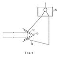
Figure 1 schematically illustrates a device for modulating an electromagnetic signal according to an embodiment; -
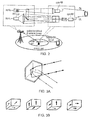
Figure 2 schematically shows the uplink signal of a mobile user to the small cell is serial-to-parallel converted into four substreams and relayed to a small-cell controller by inducing four unique polarization patterns into retro-reflected light of the controller; -
Figure 3A schematically shows a corner cube with indicated reflective properties; -
Figure 3B schematically shows four possible orientations of LC coating on the corner cube walls that are characterized by distinct polarization shifts; -
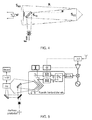
Figure 4 shows a schematic illustration of the uplink channel; -
Figure 5 schematically shows an uplink channel using multiple phase-modulating retro-reflectors characterized by mutually unique modulation patterns; -
Figure 6 schematically shows phase difference betweenStates -
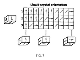
Figure 7 schematically shows an example of ten different spatial LC orientations in a corner-cube coating that are characterized by distinct polarization shifts. - Before discussing the embodiments in any more detail, first an overview will be provided.
- In the field of wireless communications, an increasing number of small cells are being deployed. The cost of their deployment is increased by the need for a wired backhaul link and power supply. If these requirements were not present then nodes for these small cells could be deployed at a far lower cost. One low power way of transmitting information to another control node is the use of modulation to modulate an electromagnetic signal that is received from that node. The received signal can be modulated with the information to be transmitted and reflected back to the node using a retro-reflector. In this way information can be transmitted in a low power manner. In some embodiments the reflected beam has been generated by a laser which provides a directional beam that will not interfere with the radio frequency communications. One potential problem is the speed with which the electromagnetic signal can be modulated. In this regard modulating means which modulate a property of the electromagnetic signal may only operate up to a certain speed. One example of a modulating means are liquid crystals mounted on the retro-reflector and controlled by an electrical signal which when applied to the liquid crystals change the direction of orientation of the crystals and this affects the optical path that the electromagnetic signal follows travelling through them. This change can be detected as a phase shift in the electromagnetic signal. The rate at which the directions of the crystals change limits the amount of information that can be transmitted in this manner.
- This has been addressed in embodiments by providing two or more modulators, the laser beam passing through each of them and each modulator modulating the signal in a mutually unique manner. If the information that is to be sent is split into two or more separate signals each containing a fraction of the information in the original signal, then the different portions of the split signal can be routed to drive the modulators in parallel, and as each signal contains less information the speed of the modulators is sufficient. The original signal can be reformed at the receiver as the modulations of each modulator are unique and can thus, be identified and separated.
-
Figure 1 shows a retro-reflector 10 according to an embodiment. The retro-reflector has modulators 12, 14 mounted on each reflective surface such that the signal passes through both modulators as it is reflected. The modulators are designed such that they modulate in mutually unique ways so that the resultant modulations can be identified as coming from one or other of the modulators. - The signal with information to be transmitted is received and is sampled and converted to a digital control signal for driving the modulators at sampler/
converter 20. The signal is split into two signals within theconverter 20 and each split signal is used to drive the two modulators in parallel. In this way a sampling frequency that is higher than the reaction time of the modulators may be used as each modulator need only operate at half of the sampling frequency. - The modulated signal that is received back at the laser beam source can be demodulated and the original signal decoded by separating out the signals from each modulator and recombining them.
- Such modulators may be particularly useful in wireless networks. In these networks operators can address the increasingly high data demand by allocating more carriers, but technically usable wireless spectrum is limited and expensive. Therefore, cellular operators have a high interest in utilizing the spectrum as efficiently as possible. In this regard, deploying small cells is the easiest way to improve the spectrum utilization by spatial re-use (so-called co-channel deployments). The network capacity can be increased linearly with the number of deployed small cells within the same spectrum.
- As a result, femtocells have become widely deployed in the past years to improve cellular indoor capacity (and coverage). In addition operators are currently interested in outdoor small cell deployments, such as ALU's lightRadio small cells.
- One major challenge for operator deployed small cells is the operation and deployment cost of such cells. Here the main issue is the provision of both power and backhaul, which make today's small cell deployment expensive.
- Considering the requirements of power and backhaul, placement options are currently very restricted. In addition, current solutions are very expensive as site rental on its own typically represents around 60% of costs associated with small cell deployment and operation.
- Therefore, any solution that can widen the potential of small cell deployment by removing or reducing those restricted requirements and associated costs would be most welcome.
- Embodiments seek to provide a novel small cell architecture which in some cases allows an energy autonomous deployment of small cells with wireless power and wireless backhaul and a small cost/ size. This can significantly reduce the deployment costs and enable cost effective large scale small cell deployments.
- Conventionally high-capacity backhaul is implemented by means of fibre optics which is very expensive to lay or rent.
- In the field of wireless communication the topology-independent fundamental problem can be viewed as how to establish multiple high-capacity wireless communication channels between two endpoints A and B, each of them being, for example a small cell, the hosting macro cell, or a cloud-RAN access point.
- To this end, embodiments propose to
- provide at least N retro-reflectors at entity B, and coat them by liquid crystal (LC) layers having N mutually distinct and pre-determined spatial orientations of the LC molecules in the absence of any control voltage,
- emit laser light from entity A to entity B, and reflect it back from B to A by using the N LC-coated retro-reflectors,
- modulate the reflected light at each of the N retro-reflectors by driving its LC layer with an input signal obtained from one of N communication channels,
- detect the N signals from N communication channels at entity A by distinguishing the "3D" phase (i.e., polarization) shift of the retro-reflected light that was caused by the variations of the optical path length in the modulated LC layers,
- the patterns of LC molecule spatial orientations are chosen in a way so that any of the polarization patterns cannot be confused by the detector of entity A with an arbitrary combination of the remaining N-1 patterns, i.e. the patterns are orthogonal or mutually unique.
- In the example of
Fig. 2 , a small-cell controller emits a laser beam to the small cell to deliver a downlink (forehaul) signal to the small cell. At the same time, an unmodulated "uplink" laser beam is pointed at four LC-coated retro-reflectors of the small cell. - As illustrated by
Fig. 3 , each of these retro-reflectors (i) reflects the incident light back along the same optical axis, and (ii) induces a distinct polarization variation in response to the modulation of its LCs by an input signal.Fig. 4 shows an example of a retro-reflector in the form of a corner cube as well as four possible LC orientations characterized by unique polarization shifts of the retro-reflected light. The four required input signals are obtained by serial-to-parallel conversion of the uplink signal from a mobile user into four substreams. - This embodiment considers the fundamental scenario consisting of a small-cell controller (SCC) and an optical-to-RF converter (ORC) that communicate by using two separate optical channels.
- Line-of-sight communications are assumed which is a standard required also for RF approaches based on 38-60 GHz mm-wave carriers.
- On the SCC side, a simple eye-safe laser of class 1M emits an optical signal having a carrier wavelength of 1550 nm (near-infrared frequency), maximum intensity of 100mW/cm2 at aperture and typical spatial divergence of 0.5 to 1 mrad. Higher eye-safe outputs are possible as specified by. The optical carrier frequency is modulated in an analog manner with a legacy RF waveform such as 3G UMTS CDMA or 4G LTE OFDM. Beams can be expanded to desired aperture intensities (i.e., output power) by standard laser beam expanders.
- On the ORC side, a receiving lens focuses the incident light onto a detecting device. This device can be for example
- a zero-bias high-speed edge-coupled unitraveling-carrier InGaAs photodiode ,
- high-power flip-chip mounted photodiode array ,
- proprietary silicon-photonics device as developed by Bell Labs and their collaborators (Tyndall Institute Ireland).
- The speed of these devices is typically at the order of units to tens of GHz, so the detected signal can be directly sent to the antenna for RF broadcast to the surrounding mobile network users. Frequency up/down-conversions and amplification are typically not required, although they can be readily incorporated into the system design.
- On the uplink, the ORC retro-reflects a light beam emitted by the SCC by using a set of retro-reflectors, consisting for example from a corner cube as depicted in
Fig. 3A . In this way, the need of perfectly and continuously (re)-aligning the uplink optical transmission with the optical axis of the downlink communication channel is eliminated. - The retro-reflected SCC light beam is modulated by input (relayed) signals. The actual RF-to-optical modulation is carried by using liquid crystal (LC) coating of the corner-cube walls that are capable of nano-second fast switching of their relative permitivity.
- By varying the permitivity of the LC coating, a phase shift of the electrical component of the retro-reflected light is induced, a phenomena that is observable at the SCC by using standard interferometry, i.e. by comparing the phase of the light at the SCC source (original signal with no phase modulation) and at the SCC receiver (retro-reflected phase-modulated light).
- By using different spatial orientation of the LC coating on different corner cubes of the ORC, orthogonal (non-interfering) channels can be implemented as described in the next.
- The relaying of the uplink signal of an LTE user is described next. The same procedure can be used for relaying optical signals from neighboring small cells or small-cell controllers, hence the corresponding description is omitted.
- The analog uplink signal from the mobile users (e.g., the 4G LTE OFDM signal) is first amplified and down-converted to baseband.
- The baseband signal is then converted to a data stream consisting for example of
- (a) the binary sequence of the LTE payload data (to this end, standard processing and decoding of the LTE signal is required),
- (b) sequence of complex in-phase and quadrature samples of the baseband signal (conversion phase is required, optionally followed by CPRI format representation),
- (c) sequence of analog samples (only sampling and hold operations are required).
- The data stream is them serial-to-parallel converted into N parallel substreams.
- The binary data from cases (a) and (b) can be then directly used to drive the LC layers of N corner cubes of the ORC as described in more detail subsequently. The analog samples in case (c) can be converted to binary data for LC control by feeding them as input to a voltage-controlled pulse train generator whose frequency/pulse width varies as function of the input voltage (see
Fig. 5 ). - In each of the N channels, if no pulse is present (binary 0 in the corresponding data substream), the molecules of LCs are in a "normal" or ground state -
State 1. If a pulse creates a voltage gradient across the LC layer (binary 1), the orientation of LC molecules changes and, excited state -State 2 is assumed. - The transition from
State 1 to/fromState 2 is characterized by a change of the optical length of the path along which the incident light travels in the LC layer. This results in a phase shift of the State-2 optical signal as compared to the original State-1 signal. By using standard interferometry and taking advantage of the fact that the SCC is the source of the retro-reflected light, the LC-induced phase shift can be detected at the SCC. -
Fig. 6 shows the phase difference betweenStates -
Fig. 7 shows the example of how ten channels can be implemented by using ten distinct patterns of LC orientation. - The LCs induce a phase shift only to the component of the electrical field of the incident light that is aligned with the orientation of the LC layer through which the light passes. Effectively, the triple reflection by the corner cube induces a polarization shift to the retro-reflected light that is unique to each channel - a property that can be detected at the SCC.
- In summary a scalable and cost-efficient solution to backhaul/forehaul provisioning using simple and mature optical technology is provided, with a high-capacity achieved by polarization multiplexing.
- Furthermore due to the retro-reflector no optical alignment on the uplink is required.
- A person of skill in the art would readily recognize that steps of various above-described methods can be performed by programmed computers. Herein, some embodiments are also intended to cover program storage devices, e.g., digital data storage media, which are machine or computer readable and encode machine-executable or computer-executable programs of instructions, wherein said instructions perform some or all of the steps of said above-described methods. The program storage devices may be, e.g., digital memories, magnetic storage media such as a magnetic disks and magnetic tapes, hard drives, or optically readable digital data storage media. The embodiments are also intended to cover computers programmed to perform said steps of the above-described methods.
- The functions of the various elements shown in the Figures, including any functional blocks labelled as "processors" or "logic", may be provided through the use of dedicated hardware as well as hardware capable of executing software in association with appropriate software. When provided by a processor, the functions may be provided by a single dedicated processor, by a single shared processor, or by a plurality of individual processors, some of which may be shared. Moreover, explicit use of the term "processor" or "controller" or "logic" should not be construed to refer exclusively to hardware capable of executing software, and may implicitly include, without limitation, digital signal processor (DSP) hardware, network processor, application specific integrated circuit (ASIC), field programmable gate array (FPGA), read only memory (ROM) for storing software, random access memory (RAM), and non-volatile storage. Other hardware, conventional and/or custom, may also be included. Similarly, any switches shown in the Figures are conceptual only. Their function may be carried out through the operation of program logic, through dedicated logic, through the interaction of program control and dedicated logic, or even manually, the particular technique being selectable by the implementer as more specifically understood from the context.
- It should be appreciated by those skilled in the art that any block diagrams herein represent conceptual views of illustrative circuitry embodying the principles of the invention. Similarly, it will be appreciated that any flow charts, flow diagrams, state transition diagrams, pseudo code, and the like represent various processes which may be substantially represented in computer readable medium and so executed by a computer or processor, whether or not such computer or processor is explicitly shown.
- The description and drawings merely illustrate the principles of the invention. It will thus be appreciated that those skilled in the art will be able to devise various arrangements that, although not explicitly described or shown herein, embody the principles of the invention and are included within its spirit and scope. Furthermore, all examples recited herein are principally intended expressly to be only for pedagogical purposes to aid the reader in understanding the principles of the invention and the concepts contributed by the inventor(s) to furthering the art, and are to be construed as being without limitation to such specifically recited examples and conditions. Moreover, all statements herein reciting principles, aspects, and embodiments of the invention, as well as specific examples thereof, are intended to encompass equivalents thereof.
Claims (15)
- A device for wirelessly transmitting information by modulating a wirelessly transmitted electromagnetic signal, said device comprising:at least one retro-reflector operable to reflect said electromagnetic signal back towards a source of said electromagnetic signal; anda modulator arranged in a path of said electromagnetic signal and operable to modulate said electromagnetic signal;said modulator comprising at least two electromagnetic modulators each operable to modulate a property of said electromagnetic signal in dependence upon a signal applied to said electromagnetic modulator, each of said electromagnetic modulators being operable to generate a different predetermined type of modulation such that modulation due to each electromagnetic modulator can be identified in said modulated signal; whereinsaid modulator comprises an input for receiving a signal comprising said information, a serial to parallel signal convertor for converting said signal into at least two parallel signals, said at least two parallel signals being applied to different ones of said at least two electromagnetic modulators.
- A device according to claim 1, wherein said electromagnetic modulators comprise light modulating material mounted on at least a portion of a surface of said at least one retro-reflector.
- A device according to claim 2, wherein said light modulating material comprises liquid crystals and said property comprises an optical path length such that a phase of said electromagnetic signal is modulated by said applied electrical signal.
- A device according to claim 3, wherein an orientation of said liquid crystals is different in said at least two electromagnetic modulators such that each electromagnetic modulator induces a distinct phase shift pattern.
- A device according to any preceding claim, wherein at least one of said retro-reflectors comprises at least two electromagnetic modulators.
- A device according to claim 5, wherein at least two of said at least two electromagnetic modulators are driven by a same electrical signal.
- A device according to claim 5 or 6, wherein at least two of said at least two electromagnetic modulators are driven by a different electrical signal.
- A device according to any preceding claim, comprising:a predetermined number of electromagnetic modulators each operable to generate a different predetermined type of modulation, and further electromagnetic modulators said further electromagnetic modulators each operable to generate a same predetermined type of modulation as one of said predetermined number of electromagnetic modulators, whereinat least two of said electromagnetic modulators are mounted such that said electromagnetic signal passes through both of said at least two electromagnetic modulators, and a same electrical signal is applied to said at least two electromagnetic modulators, modulation of said electromagnetic signal modulated by said at least two electromagnetic modulators being a combination of modulation caused by each of said at least two electromagnetic modulators, wherein said different predetermined types of modulation and said combinations are such that modulation due to each of said electrical signals can be identified in said modulated signal.
- A device according to claim 8, comprising a plurality of retro-reflectors a number of said plurality of retro-reflectors being greater than said predetermined number.
- A device according to any preceding claim, wherein said electromagnetic signal is a laser beam.
- A device according to any preceding claim, wherein said serial to parallel converter comprises a sampler for sampling said signal an output of said sampler during different subsets of time comprising said at least two parallel signals.
- A network node or supporting communication with user equipment of a wireless telecommunication network, said network node comprising:an antenna for receiving and transmitting wireless telecommunication communication signals to a user equipment, said wireless telecommunication signals being within a first frequency band; andreceiver for receiving an electromagnetic signal and a device according to any preceding claim for modulating said electromagnetic signal in response to a signal received from said user equipment, said electromagnetic signal being in a second frequency band different to said first frequency band.
- A method for wirelessly transmitting information by modulating an electromagnetic signal comprising:reflecting said electromagnetic signal back towards a source of said electromagnetic signal using a retro-reflector;receiving a signal comprising said information;converting said signal into at least two parallel electrical signals;applying said at least two parallel electrical signals to different ones of at least two electromagnetic modulators;modulating at least one property of said electromagnetic signal with said at least two electromagnetic modulators, each of said electromagnetic modulators being operable to generate a different predetermined type of modulation such that modulation due to each electromagnetic modulator can be identified in said modulated signal.
- A device for receiving and demodulating a signal, comprising:a transmitter operable to transmit an electromagnetic signal wirelessly towards a signalling device;a receiver operable to receive an electromagnetic signal, said electromagnetic signal comprising said electromagnetic signal transmitted by said transmitter and modulated by and reflected from said signalling device;a demodulator operable to demodulate said received electromagnetic signal, said demodulator being operable to access modulation data for said electromagnetic signal indicating a plurality of phase shift patterns applied by a plurality of modulators on said signalling device and a sequence in which said signal was split and fed to said plurality of modulators, said demodulator identifying portions of said electromagnetic signal modulated by each of said plurality of modulators and demodulating and combining said signals in said sequence to form a demodulated signal.
- A network controller node for supporting communication with user equipment of a wireless telecommunication network, said network controller node comprising:a device according to claim 14 operable to transmit electromagnetic signals wirelessly towards a network node of said wireless telecommunication network, at least one of said electromagnetic signals comprising downlink data for user equipment communicating with said network node; whereinsaid demodulator is operable to demodulate said received electromagnetic signal to extract uplink data from user equipment communicating with said network node; andsaid device is operable to transmit said electromagnetic signals in a second frequency band towards said network node, said user equipment communicating with said network nodes in a first frequency band, said second frequency band being a different frequency band to said first frequency band.
Priority Applications (1)
| Application Number | Priority Date | Filing Date | Title |
|---|---|---|---|
| EP15305466.3A EP3076566B1 (en) | 2015-03-31 | 2015-03-31 | Information transmission by electromagnetic signal modulation |
Applications Claiming Priority (1)
| Application Number | Priority Date | Filing Date | Title |
|---|---|---|---|
| EP15305466.3A EP3076566B1 (en) | 2015-03-31 | 2015-03-31 | Information transmission by electromagnetic signal modulation |
Publications (2)
| Publication Number | Publication Date |
|---|---|
| EP3076566A1 true EP3076566A1 (en) | 2016-10-05 |
| EP3076566B1 EP3076566B1 (en) | 2019-01-02 |
Family
ID=52946488
Family Applications (1)
| Application Number | Title | Priority Date | Filing Date |
|---|---|---|---|
| EP15305466.3A Active EP3076566B1 (en) | 2015-03-31 | 2015-03-31 | Information transmission by electromagnetic signal modulation |
Country Status (1)
| Country | Link |
|---|---|
| EP (1) | EP3076566B1 (en) |
Citations (4)
| Publication number | Priority date | Publication date | Assignee | Title |
|---|---|---|---|---|
| WO2002005459A2 (en) * | 2000-07-11 | 2002-01-17 | Quantumbeam Limited | Optical free space signalling system |
| US20060269294A1 (en) * | 2005-05-31 | 2006-11-30 | Hitachi Communication Technologies, Ltd. | Optical transmission equipment and integrated circuit |
| WO2014085574A2 (en) * | 2012-11-30 | 2014-06-05 | Corning Incorporated | Method of measuring multi-mode fiber optical properties during processing of the fiber |
| US20150078748A1 (en) * | 2013-09-18 | 2015-03-19 | Sumitomo Electric Industries, Ltd. | Wavelength selective switch |
-
2015
- 2015-03-31 EP EP15305466.3A patent/EP3076566B1/en active Active
Patent Citations (4)
| Publication number | Priority date | Publication date | Assignee | Title |
|---|---|---|---|---|
| WO2002005459A2 (en) * | 2000-07-11 | 2002-01-17 | Quantumbeam Limited | Optical free space signalling system |
| US20060269294A1 (en) * | 2005-05-31 | 2006-11-30 | Hitachi Communication Technologies, Ltd. | Optical transmission equipment and integrated circuit |
| WO2014085574A2 (en) * | 2012-11-30 | 2014-06-05 | Corning Incorporated | Method of measuring multi-mode fiber optical properties during processing of the fiber |
| US20150078748A1 (en) * | 2013-09-18 | 2015-03-19 | Sumitomo Electric Industries, Ltd. | Wavelength selective switch |
Also Published As
| Publication number | Publication date |
|---|---|
| EP3076566B1 (en) | 2019-01-02 |
Similar Documents
| Publication | Publication Date | Title |
|---|---|---|
| Basar et al. | Reconfigurable intelligent surfaces for 6G: Emerging hardware architectures, applications, and open challenges | |
| Rajatheva et al. | Scoring the terabit/s goal: Broadband connectivity in 6G | |
| JP7750965B2 (en) | Systems and methods for reflective intelligent surfaces in MIMO systems | |
| US20230308139A1 (en) | Systems and methods for mimo communication with controllable environments | |
| Raddo et al. | Transition technologies towards 6G networks | |
| Kawanishi et al. | Wired and wireless links to bridge networks: Seamlessly connecting radio and optical technologies for 5G networks | |
| Fara et al. | Reconfigurable intelligent surface-assisted ambient backscatter communications–experimental assessment | |
| Esmail et al. | Investigation and demonstration of high speed full-optical hybrid FSO/fiber communication system under light sand storm condition | |
| Wang et al. | Microwave photonics empowered integrated sensing and communication for 6G | |
| TW201521374A (en) | Transmitter method for supporting a determination of a set of beamforming weights by a receiver method, receiver method, transmitter apparatus, receiver apparatus and network node thereof | |
| US12218789B2 (en) | Frequency gradient metasurface device and method based on fast beam steering system | |
| US20250343577A1 (en) | Systems and methods for over-the-air interferometer based modulation | |
| KR20260021612A (en) | Shifted backscattering-based channel estimation for wireless power transfer to passive devices | |
| Ruggeri et al. | Multi-user IFoF uplink transmission over a 32-element 60GHz phased array antenna enabling both Frequency and Spatial Division Multiplexing | |
| KR102781521B1 (en) | Method and device for correcting polarization distortion of faraday rotation mirror in plug-and-play quantum key distribution system | |
| EP3076566B1 (en) | Information transmission by electromagnetic signal modulation | |
| US12294414B2 (en) | Method and device for multi-wavelength plug-and-play quantum key distribution without time delay due to wavelength conversion | |
| Ruggeri et al. | Fiber wireless A-RoF/IFoF uplink of 0.4 Gb/s 16-QAM and 0.6 Gb/s QPSK over a 32-element 60GHz phased array antenna for 5G fronthaul networks | |
| Dat et al. | Photonics-enabled terahertz signal processing for extreme communications in 6G and beyond | |
| EP3076201A1 (en) | Optical communication and energy transmission from a base station controller to battery-less remote radio head (rrh) | |
| CN120513652A (en) | Communication method and device | |
| CN109921856B (en) | A low-speed communication method and system based on light scintillation of low-orbit satellites | |
| CN120604530A (en) | Communication method and device | |
| Rana et al. | Beyond 5G enabled internet-of-things for next generation smart systems: A use case scenario | |
| US12431943B2 (en) | Method for controlling beam in wireless communication system, and apparatus therefor |
Legal Events
| Date | Code | Title | Description |
|---|---|---|---|
| PUAI | Public reference made under article 153(3) epc to a published international application that has entered the european phase |
Free format text: ORIGINAL CODE: 0009012 |
|
| AK | Designated contracting states |
Kind code of ref document: A1 Designated state(s): AL AT BE BG CH CY CZ DE DK EE ES FI FR GB GR HR HU IE IS IT LI LT LU LV MC MK MT NL NO PL PT RO RS SE SI SK SM TR |
|
| AX | Request for extension of the european patent |
Extension state: BA ME |
|
| STAA | Information on the status of an ep patent application or granted ep patent |
Free format text: STATUS: REQUEST FOR EXAMINATION WAS MADE |
|
| 17P | Request for examination filed |
Effective date: 20170405 |
|
| RBV | Designated contracting states (corrected) |
Designated state(s): AL AT BE BG CH CY CZ DE DK EE ES FI FR GB GR HR HU IE IS IT LI LT LU LV MC MK MT NL NO PL PT RO RS SE SI SK SM TR |
|
| RAP1 | Party data changed (applicant data changed or rights of an application transferred) |
Owner name: ALCATEL LUCENT |
|
| GRAP | Despatch of communication of intention to grant a patent |
Free format text: ORIGINAL CODE: EPIDOSNIGR1 |
|
| STAA | Information on the status of an ep patent application or granted ep patent |
Free format text: STATUS: GRANT OF PATENT IS INTENDED |
|
| INTG | Intention to grant announced |
Effective date: 20180723 |
|
| RIN1 | Information on inventor provided before grant (corrected) |
Inventor name: BULJA, SENAD Inventor name: KUCERA, STEPAN |
|
| GRAS | Grant fee paid |
Free format text: ORIGINAL CODE: EPIDOSNIGR3 |
|
| GRAA | (expected) grant |
Free format text: ORIGINAL CODE: 0009210 |
|
| STAA | Information on the status of an ep patent application or granted ep patent |
Free format text: STATUS: THE PATENT HAS BEEN GRANTED |
|
| AK | Designated contracting states |
Kind code of ref document: B1 Designated state(s): AL AT BE BG CH CY CZ DE DK EE ES FI FR GB GR HR HU IE IS IT LI LT LU LV MC MK MT NL NO PL PT RO RS SE SI SK SM TR |
|
| REG | Reference to a national code |
Ref country code: GB Ref legal event code: FG4D |
|
| REG | Reference to a national code |
Ref country code: CH Ref legal event code: EP Ref country code: AT Ref legal event code: REF Ref document number: 1085751 Country of ref document: AT Kind code of ref document: T Effective date: 20190115 |
|
| REG | Reference to a national code |
Ref country code: DE Ref legal event code: R096 Ref document number: 602015022691 Country of ref document: DE |
|
| REG | Reference to a national code |
Ref country code: IE Ref legal event code: FG4D |
|
| REG | Reference to a national code |
Ref country code: NL Ref legal event code: FP |
|
| REG | Reference to a national code |
Ref country code: LT Ref legal event code: MG4D |
|
| REG | Reference to a national code |
Ref country code: AT Ref legal event code: MK05 Ref document number: 1085751 Country of ref document: AT Kind code of ref document: T Effective date: 20190102 |
|
| PG25 | Lapsed in a contracting state [announced via postgrant information from national office to epo] |
Ref country code: FI Free format text: LAPSE BECAUSE OF FAILURE TO SUBMIT A TRANSLATION OF THE DESCRIPTION OR TO PAY THE FEE WITHIN THE PRESCRIBED TIME-LIMIT Effective date: 20190102 Ref country code: NO Free format text: LAPSE BECAUSE OF FAILURE TO SUBMIT A TRANSLATION OF THE DESCRIPTION OR TO PAY THE FEE WITHIN THE PRESCRIBED TIME-LIMIT Effective date: 20190402 Ref country code: LT Free format text: LAPSE BECAUSE OF FAILURE TO SUBMIT A TRANSLATION OF THE DESCRIPTION OR TO PAY THE FEE WITHIN THE PRESCRIBED TIME-LIMIT Effective date: 20190102 Ref country code: PL Free format text: LAPSE BECAUSE OF FAILURE TO SUBMIT A TRANSLATION OF THE DESCRIPTION OR TO PAY THE FEE WITHIN THE PRESCRIBED TIME-LIMIT Effective date: 20190102 Ref country code: ES Free format text: LAPSE BECAUSE OF FAILURE TO SUBMIT A TRANSLATION OF THE DESCRIPTION OR TO PAY THE FEE WITHIN THE PRESCRIBED TIME-LIMIT Effective date: 20190102 Ref country code: PT Free format text: LAPSE BECAUSE OF FAILURE TO SUBMIT A TRANSLATION OF THE DESCRIPTION OR TO PAY THE FEE WITHIN THE PRESCRIBED TIME-LIMIT Effective date: 20190502 Ref country code: SE Free format text: LAPSE BECAUSE OF FAILURE TO SUBMIT A TRANSLATION OF THE DESCRIPTION OR TO PAY THE FEE WITHIN THE PRESCRIBED TIME-LIMIT Effective date: 20190102 |
|
| PG25 | Lapsed in a contracting state [announced via postgrant information from national office to epo] |
Ref country code: LV Free format text: LAPSE BECAUSE OF FAILURE TO SUBMIT A TRANSLATION OF THE DESCRIPTION OR TO PAY THE FEE WITHIN THE PRESCRIBED TIME-LIMIT Effective date: 20190102 Ref country code: RS Free format text: LAPSE BECAUSE OF FAILURE TO SUBMIT A TRANSLATION OF THE DESCRIPTION OR TO PAY THE FEE WITHIN THE PRESCRIBED TIME-LIMIT Effective date: 20190102 Ref country code: GR Free format text: LAPSE BECAUSE OF FAILURE TO SUBMIT A TRANSLATION OF THE DESCRIPTION OR TO PAY THE FEE WITHIN THE PRESCRIBED TIME-LIMIT Effective date: 20190403 Ref country code: BG Free format text: LAPSE BECAUSE OF FAILURE TO SUBMIT A TRANSLATION OF THE DESCRIPTION OR TO PAY THE FEE WITHIN THE PRESCRIBED TIME-LIMIT Effective date: 20190402 Ref country code: IS Free format text: LAPSE BECAUSE OF FAILURE TO SUBMIT A TRANSLATION OF THE DESCRIPTION OR TO PAY THE FEE WITHIN THE PRESCRIBED TIME-LIMIT Effective date: 20190502 Ref country code: HR Free format text: LAPSE BECAUSE OF FAILURE TO SUBMIT A TRANSLATION OF THE DESCRIPTION OR TO PAY THE FEE WITHIN THE PRESCRIBED TIME-LIMIT Effective date: 20190102 |
|
| REG | Reference to a national code |
Ref country code: DE Ref legal event code: R097 Ref document number: 602015022691 Country of ref document: DE |
|
| PG25 | Lapsed in a contracting state [announced via postgrant information from national office to epo] |
Ref country code: AT Free format text: LAPSE BECAUSE OF FAILURE TO SUBMIT A TRANSLATION OF THE DESCRIPTION OR TO PAY THE FEE WITHIN THE PRESCRIBED TIME-LIMIT Effective date: 20190102 Ref country code: DK Free format text: LAPSE BECAUSE OF FAILURE TO SUBMIT A TRANSLATION OF THE DESCRIPTION OR TO PAY THE FEE WITHIN THE PRESCRIBED TIME-LIMIT Effective date: 20190102 Ref country code: MC Free format text: LAPSE BECAUSE OF FAILURE TO SUBMIT A TRANSLATION OF THE DESCRIPTION OR TO PAY THE FEE WITHIN THE PRESCRIBED TIME-LIMIT Effective date: 20190102 Ref country code: SK Free format text: LAPSE BECAUSE OF FAILURE TO SUBMIT A TRANSLATION OF THE DESCRIPTION OR TO PAY THE FEE WITHIN THE PRESCRIBED TIME-LIMIT Effective date: 20190102 Ref country code: AL Free format text: LAPSE BECAUSE OF FAILURE TO SUBMIT A TRANSLATION OF THE DESCRIPTION OR TO PAY THE FEE WITHIN THE PRESCRIBED TIME-LIMIT Effective date: 20190102 Ref country code: IT Free format text: LAPSE BECAUSE OF FAILURE TO SUBMIT A TRANSLATION OF THE DESCRIPTION OR TO PAY THE FEE WITHIN THE PRESCRIBED TIME-LIMIT Effective date: 20190102 Ref country code: EE Free format text: LAPSE BECAUSE OF FAILURE TO SUBMIT A TRANSLATION OF THE DESCRIPTION OR TO PAY THE FEE WITHIN THE PRESCRIBED TIME-LIMIT Effective date: 20190102 Ref country code: CZ Free format text: LAPSE BECAUSE OF FAILURE TO SUBMIT A TRANSLATION OF THE DESCRIPTION OR TO PAY THE FEE WITHIN THE PRESCRIBED TIME-LIMIT Effective date: 20190102 Ref country code: RO Free format text: LAPSE BECAUSE OF FAILURE TO SUBMIT A TRANSLATION OF THE DESCRIPTION OR TO PAY THE FEE WITHIN THE PRESCRIBED TIME-LIMIT Effective date: 20190102 |
|
| REG | Reference to a national code |
Ref country code: CH Ref legal event code: PL |
|
| PLBE | No opposition filed within time limit |
Free format text: ORIGINAL CODE: 0009261 |
|
| STAA | Information on the status of an ep patent application or granted ep patent |
Free format text: STATUS: NO OPPOSITION FILED WITHIN TIME LIMIT |
|
| PG25 | Lapsed in a contracting state [announced via postgrant information from national office to epo] |
Ref country code: LU Free format text: LAPSE BECAUSE OF NON-PAYMENT OF DUE FEES Effective date: 20190331 Ref country code: SM Free format text: LAPSE BECAUSE OF FAILURE TO SUBMIT A TRANSLATION OF THE DESCRIPTION OR TO PAY THE FEE WITHIN THE PRESCRIBED TIME-LIMIT Effective date: 20190102 |
|
| REG | Reference to a national code |
Ref country code: BE Ref legal event code: MM Effective date: 20190331 |
|
| 26N | No opposition filed |
Effective date: 20191003 |
|
| PG25 | Lapsed in a contracting state [announced via postgrant information from national office to epo] |
Ref country code: IE Free format text: LAPSE BECAUSE OF NON-PAYMENT OF DUE FEES Effective date: 20190331 Ref country code: CH Free format text: LAPSE BECAUSE OF NON-PAYMENT OF DUE FEES Effective date: 20190331 Ref country code: LI Free format text: LAPSE BECAUSE OF NON-PAYMENT OF DUE FEES Effective date: 20190331 |
|
| PG25 | Lapsed in a contracting state [announced via postgrant information from national office to epo] |
Ref country code: BE Free format text: LAPSE BECAUSE OF NON-PAYMENT OF DUE FEES Effective date: 20190331 Ref country code: SI Free format text: LAPSE BECAUSE OF FAILURE TO SUBMIT A TRANSLATION OF THE DESCRIPTION OR TO PAY THE FEE WITHIN THE PRESCRIBED TIME-LIMIT Effective date: 20190102 |
|
| PG25 | Lapsed in a contracting state [announced via postgrant information from national office to epo] |
Ref country code: TR Free format text: LAPSE BECAUSE OF FAILURE TO SUBMIT A TRANSLATION OF THE DESCRIPTION OR TO PAY THE FEE WITHIN THE PRESCRIBED TIME-LIMIT Effective date: 20190102 |
|
| PG25 | Lapsed in a contracting state [announced via postgrant information from national office to epo] |
Ref country code: MT Free format text: LAPSE BECAUSE OF NON-PAYMENT OF DUE FEES Effective date: 20190331 |
|
| PG25 | Lapsed in a contracting state [announced via postgrant information from national office to epo] |
Ref country code: CY Free format text: LAPSE BECAUSE OF FAILURE TO SUBMIT A TRANSLATION OF THE DESCRIPTION OR TO PAY THE FEE WITHIN THE PRESCRIBED TIME-LIMIT Effective date: 20190102 |
|
| PG25 | Lapsed in a contracting state [announced via postgrant information from national office to epo] |
Ref country code: HU Free format text: LAPSE BECAUSE OF FAILURE TO SUBMIT A TRANSLATION OF THE DESCRIPTION OR TO PAY THE FEE WITHIN THE PRESCRIBED TIME-LIMIT; INVALID AB INITIO Effective date: 20150331 |
|
| PGFP | Annual fee paid to national office [announced via postgrant information from national office to epo] |
Ref country code: NL Payment date: 20220215 Year of fee payment: 8 Ref country code: FR Payment date: 20220209 Year of fee payment: 8 |
|
| PG25 | Lapsed in a contracting state [announced via postgrant information from national office to epo] |
Ref country code: MK Free format text: LAPSE BECAUSE OF FAILURE TO SUBMIT A TRANSLATION OF THE DESCRIPTION OR TO PAY THE FEE WITHIN THE PRESCRIBED TIME-LIMIT Effective date: 20190102 |
|
| REG | Reference to a national code |
Ref country code: NL Ref legal event code: MM Effective date: 20230401 |
|
| PG25 | Lapsed in a contracting state [announced via postgrant information from national office to epo] |
Ref country code: NL Free format text: LAPSE BECAUSE OF NON-PAYMENT OF DUE FEES Effective date: 20230401 |
|
| PG25 | Lapsed in a contracting state [announced via postgrant information from national office to epo] |
Ref country code: FR Free format text: LAPSE BECAUSE OF NON-PAYMENT OF DUE FEES Effective date: 20230331 |
|
| PGFP | Annual fee paid to national office [announced via postgrant information from national office to epo] |
Ref country code: GB Payment date: 20260209 Year of fee payment: 12 |
|
| PGFP | Annual fee paid to national office [announced via postgrant information from national office to epo] |
Ref country code: DE Payment date: 20260204 Year of fee payment: 12 |