EP3076521A1 - Rotor, method of manufacturing the same, and motor including the rotor - Google Patents
Rotor, method of manufacturing the same, and motor including the rotor Download PDFInfo
- Publication number
- EP3076521A1 EP3076521A1 EP16162978.7A EP16162978A EP3076521A1 EP 3076521 A1 EP3076521 A1 EP 3076521A1 EP 16162978 A EP16162978 A EP 16162978A EP 3076521 A1 EP3076521 A1 EP 3076521A1
- Authority
- EP
- European Patent Office
- Prior art keywords
- rotor
- rotor core
- magnet insertion
- insertion holes
- magnet
- Prior art date
- Legal status (The legal status is an assumption and is not a legal conclusion. Google has not performed a legal analysis and makes no representation as to the accuracy of the status listed.)
- Withdrawn
Links
Images


Classifications
-
- H—ELECTRICITY
- H02—GENERATION; CONVERSION OR DISTRIBUTION OF ELECTRIC POWER
- H02K—DYNAMO-ELECTRIC MACHINES
- H02K1/00—Details of the magnetic circuit
- H02K1/06—Details of the magnetic circuit characterised by the shape, form or construction
- H02K1/22—Rotating parts of the magnetic circuit
- H02K1/27—Rotor cores with permanent magnets
- H02K1/2706—Inner rotors
- H02K1/272—Inner rotors the magnetisation axis of the magnets being perpendicular to the rotor axis
- H02K1/274—Inner rotors the magnetisation axis of the magnets being perpendicular to the rotor axis the rotor consisting of two or more circumferentially positioned magnets
- H02K1/2753—Inner rotors the magnetisation axis of the magnets being perpendicular to the rotor axis the rotor consisting of two or more circumferentially positioned magnets the rotor consisting of magnets or groups of magnets arranged with alternating polarity
- H02K1/278—Surface mounted magnets; Inset magnets
-
- H—ELECTRICITY
- H02—GENERATION; CONVERSION OR DISTRIBUTION OF ELECTRIC POWER
- H02K—DYNAMO-ELECTRIC MACHINES
- H02K1/00—Details of the magnetic circuit
- H02K1/06—Details of the magnetic circuit characterised by the shape, form or construction
- H02K1/22—Rotating parts of the magnetic circuit
- H02K1/27—Rotor cores with permanent magnets
- H02K1/2706—Inner rotors
- H02K1/272—Inner rotors the magnetisation axis of the magnets being perpendicular to the rotor axis
- H02K1/274—Inner rotors the magnetisation axis of the magnets being perpendicular to the rotor axis the rotor consisting of two or more circumferentially positioned magnets
- H02K1/2753—Inner rotors the magnetisation axis of the magnets being perpendicular to the rotor axis the rotor consisting of two or more circumferentially positioned magnets the rotor consisting of magnets or groups of magnets arranged with alternating polarity
- H02K1/276—Magnets embedded in the magnetic core, e.g. interior permanent magnets [IPM]
-
- H—ELECTRICITY
- H02—GENERATION; CONVERSION OR DISTRIBUTION OF ELECTRIC POWER
- H02K—DYNAMO-ELECTRIC MACHINES
- H02K1/00—Details of the magnetic circuit
- H02K1/06—Details of the magnetic circuit characterised by the shape, form or construction
- H02K1/22—Rotating parts of the magnetic circuit
- H02K1/28—Means for mounting or fastening rotating magnetic parts on to, or to, the rotor structures
-
- H—ELECTRICITY
- H02—GENERATION; CONVERSION OR DISTRIBUTION OF ELECTRIC POWER
- H02K—DYNAMO-ELECTRIC MACHINES
- H02K15/00—Processes or apparatus specially adapted for manufacturing, assembling, maintaining or repairing of dynamo-electric machines
- H02K15/02—Processes or apparatus specially adapted for manufacturing, assembling, maintaining or repairing of dynamo-electric machines of stator or rotor bodies
- H02K15/03—Processes or apparatus specially adapted for manufacturing, assembling, maintaining or repairing of dynamo-electric machines of stator or rotor bodies having permanent magnets
-
- H—ELECTRICITY
- H02—GENERATION; CONVERSION OR DISTRIBUTION OF ELECTRIC POWER
- H02K—DYNAMO-ELECTRIC MACHINES
- H02K21/00—Synchronous motors having permanent magnets; Synchronous generators having permanent magnets
- H02K21/12—Synchronous motors having permanent magnets; Synchronous generators having permanent magnets with stationary armatures and rotating magnets
- H02K21/14—Synchronous motors having permanent magnets; Synchronous generators having permanent magnets with stationary armatures and rotating magnets with magnets rotating within the armatures
-
- H—ELECTRICITY
- H02—GENERATION; CONVERSION OR DISTRIBUTION OF ELECTRIC POWER
- H02K—DYNAMO-ELECTRIC MACHINES
- H02K2213/00—Specific aspects, not otherwise provided for and not covered by codes H02K2201/00 - H02K2211/00
- H02K2213/03—Machines characterised by numerical values, ranges, mathematical expressions or similar information
Definitions
- the present invention relates to a motor for a vehicle and a rotor applied to the motor.
- the rotor structure applied to an interior permanent magnet (IPM) motor has a structure in which a magnet is inserted into a stacked rotor core formed by stacking a plurality of rotor core members with a disk-shape.
- the magnet inserted into the rotor core fixedly adheres to a magnet insertion hole using an adhesive, etc.
- a method of fixing using only an adhesive causes problems in which the magnet moves from an initial mounting position, a foreign material due to delamination of the adhesive is generated, and the magnet cannot be fixed due to glass transition at a high temperature since adhesion of the adhesive fixing the magnet is degraded when the motor is used for a long period or is used for long hours at a high temperature.
- an adhesive capable of enduring a high temperature is required, but an application of the adhesive is difficult due to some problems of costs, ensuring permanent stability during high speed rotation, and economic feasibility.
- the present invention is directed to a motor which is reliable by fixedly inserting magnets inserted into a rotor with no adhesive and implementing a magnet fixing pattern at a peripheral portion of a magnet insertion hole in an upper surface of a rotor member so as to eliminate an unstable operation and foreign material generation due to adhesive delamination caused by an external environmental change, and particularly, may prevent noises and vibrations due to a fixing defect of the magnet from being generated and also reduce process costs by implementing a stable fixing structure of the magnet using a fixing method by an axial pressure of the rotor.
- a rotor including a rotor core in which a plurality of rotor core members are stacked and a plurality of magnets inserted into magnet insertion holes of the rotor core, and further including fixing patterns that protrude toward the center of the magnet insertion holes from one sides of the magnet insertion holes of the rotor core members respectively disposed at an uppermost layer and a lowermost layer.
- the rotor with the above described structure is implemented as a motor by including a motor housing, a stator disposed at the motor housing, a rotor disposed in the stator, and a shaft passing through the center of the rotor.
- FIG. 1 is a schematic view for describing a structure of a rotor according to an embodiment of the present invention
- FIG. 2 is a schematic view showing an enlarged main portion of the rotor in FIG. 1
- FIG. 3 is a cross-sectional schematic view for describing a structure of the rotor according to the embodiment of the present invention
- FIG. 4 is a process schematic view for describing a process of manufacturing the rotor according to the embodiment of the present invention.
- a rotor 100 may include a rotor core 110 in which a plurality of rotor core members are stacked and a plurality of magnets 150 inserted into the rotor core 110.
- the rotor 100 may further include fixing patterns 112.
- the fixing patterns 112 may protrude toward the center of magnet insertion holes from one sides of the magnet inserting holes of outermost rotor core members of the rotor core members implemented in a multilayer structure.
- the fixing patterns 112 are implemented in a protruding structure from an edge part of the magnet insertion hole in a center direction.
- the fixing patterns 112 may fixedly support an upper surface or a lower surface of the magnet 150.
- the fixing patterns may be implemented as separate members, but, preferably, may be integrally implemented with the magnet insertion holes.
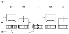
- the fixing pattern 112 may be implemented to have an upper surface of a boundary portion protruding by a predetermined amount toward the magnet insertion hole by pressurizing a boundary area in which the magnet insertion hole of an uppermost magnet member is formed (see FIG. 4 ).
- the fixing patterns 112 are integrally implemented with a magnet member, more structural stability may be ensured, the above-described magnet may be stably fixed in the rotor core 110 using the fixing patterns 112, a problem caused by an adhesive may be solved, and uniform reliability may also be ensured by implementing a fixing structure without using a separate adhesive (hereinafter, referred to as 'a non-adhesive coupling structure').
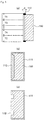
- FIG. 3 is a cross-sectional schematic view illustrating a structure of the fixing pattern 112.
- the fixing pattern 112 may be implemented in a protruding structure which fixedly supports the upper surface and the lower surface of the magnet 150 inserted into the rotor core 110 in which the plurality of rotor core members are stacked.
- the fixing pattern 112 may be implemented in a structure which protrudes inward from the boundary portion of the magnet insertion hole and, as shown in FIG. 3(A) and 3(B) , the fixing patterns 112 may be implemented in a structure which covers a part of the upper surface or the lower surface of the magnet 150.
- the fixing patterns 112 may be implemented to protrude from side surfaces of the magnet insertion holes by 0.3 to 1.0 mm.
- a thickness of the protrusion When a thickness of the protrusion is less than 0.3 mm, a fixing force is weakened, and thus it is difficult to prevent the magnet from being separated.
- a thickness of the protrusion When the thickness of the protrusion is greater than 1.0 mm, a fixing force is increased, but a thickness deviation of the rotor core members with uniform thickness is influenced, and thus it is difficult to form a reliable magnetic force.
- thicknesses T1 and T2 of the rotor core members disposed at an uppermost layer and a lowermost layer of the rotor core may be greater than thicknesses T3 and T4 of the rotor core member.
- a change of the magnet member expanding to protrude from the boundary portion of the magnet insertion hole by pressurization is reduced, and an error due to the thickness deviation of each rotor core member may be reduced.
- a ratio of the thicknesses T1 and T2 of the rotor core members disposed at the uppermost layer and the lowermost layer of the rotor core to the thicknesses T3 and T4 of the remaining rotor core members may satisfy a range of 1.1 to 2.0:1.
- structures of various fixing patterns according to the embodiment of the present invention may be variously changed in a shape having, as shown in FIG. 3(B) , a structure in which a fixing pattern is in surface contact with a predetermined area of the upper surface or the lower surface of the magnet or, as shown in FIG. 3(C) , a structure in which a plurality of protruding compositions are formed.
- a plurality of rotor core members are stacked to form a rotor core 110, (b) fixing patterns are implemented by pressurizing boundary portions of the magnet insertion holes of the uppermost surface using a jig J, (c) magnets are inserted into the magnet insertion holes by rotating the rotor core 110, (d) the rotor core is fixed again, and (e) the fixing patterns are implemented by pressurizing boundary portions of the magnet insertion holes of the lowermost surface using the jig, and thus the magnets may be mounted and stably fixed.
- a process of operation (b) and a process of operation (c) may be performed in reverse order. That is, the magnets are inserted first, and then the fixing patterns may be implemented on the upper and lower parts of the rotor core.
- FIGS. 1 and 2 another configuration of the rotor according to the embodiment of the present invention will be described.
- the rotor core 110 is a composition formed by stacking a plurality of rotor core members with a thin planar disk shape.
- the rotor core member has a thin planar disk shape and is made of a steel sheet with a thickness of about 0.5 mm.
- the rotor core members are formed by performing a punching process on a thin steel sheet and are stacked to form the rotor core 110.
- a shaft coupling hole 140 to which a shaft is coupled is subsequently provided, and the shaft is pressed in and coupled to the shaft coupling hole 140, and thus the rotor core is installed in a motor to be rotated about the shaft.
- a plurality of magnet insertion holes 111 may be provided in the rotor core 110.
- the magnet insertion holes 111 may have a hole shape extending in a longitudinal direction of the rotor core 110 so that a plurality of magnets are inserted thereinto.
- the magnets 150 inserted and coupled in parallel to a central axis of the shaft coupling hole 140 are inserted into and coupled to the magnet insertion holes 111.
- the plurality of magnet insertion holes 111 be penetrated at regular intervals and, according to the embodiment of the present invention, 8 magnet inserting holes 111 are preferably disposed in a regular octagonal shape along an outer circumferential surface of the rotor core 110.
- the fixing patterns 112 according to the embodiment of the present invention may protrude from the upper boundary portions of the magnet insertion holes 111 as described above.
- the number of magnet inserting holes 111 are increased or decreased rather than the 8 holes depending on a change in the size of the rotor core, or the like so that the magnet inserting holes may be disposed in a regular pentagonal shape (5 holes) or a regular hexagonal shape (6 holes), or the 8 magnet insertion holes or more may be provided.
- the magnets and the magnet insertion holes are coupled to each other in a non-adhesive structure in which an adhesive material, such as an adhesive, etc., is not used between the magnet insertion holes 111 and the magnets 150 to be inserted, and the entirety or a part of an inner surface of the magnet insertion hole is in direct surface contact with an outer surface of the magnet with no adhesive.
- a pair of fixing plates 120 and 130 are disposed on an upper surface and a lower surface of the rotor core 110, and the fixing plates 120 and 130 are in surface contact with an uppermost surface and a lowermost surface of the multilayer structure of the rotor core member to be pressed in and coupled thereto.
- the fixing plate 120 hereinafter, referred to as 'a first fixing plate'
- the fixing plate 120 disposed on a lower surface of the rotor core 110 of the fixing plates may be, as described above, implemented in a structure which compensates for an axial supporting force of the magnet by including a plurality of magnet fixing indentation patterns 121 that are predetermined protruding patterns formed by a surface process.
- the first fixing plate 120 and the second fixing plate 130 are formed in a disk shape having a diameter corresponding to a diameter of the rotor core member, are formed so that all portions except for through holes H1 and H2 in the center of the plates into which the shaft will be inserted are blocked, and are processed so that the magnet fixing indentation patterns 121 implementing a non-adhesive coupling structure protrude.
- the through holes H1 and H2 are formed to correspond to a diameter of the shaft to be coupled with the fixing plates.
- the first and second fixing plates have a thickness corresponding to the thickness of the rotor core member or the thickness of the first and the second fixing plates may be a little bit greater than that of the rotor core member. Also, it is preferable that the first and second fixing plates be formed to have a minimal thickness to miniaturize the rotor core 110.
- the fixing plates and the rotor core member be easily fixed by a mutual interference and a plasticity deformation through a press-in process and be changed at the same coefficient of thermal expansion when thermal expansion and contraction are performed
- the first and second fixing plates 120 and 130 be formed of the same material as the rotor core members.
- the first and second fixing plates 120 and 130 be respectively coupled to exposed uppermost and lowermost surfaces of the rotor core 110 by a pressing force by the press-in process without a separate fixing unit and be in surface contact with the exposed surfaces of both ends of the rotor core 110.
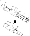
- FIG. 5 illustrates an operational state view in which the rotor according to the embodiment of the present invention described in FIGS. 1 to 3 is coupled to a shaft and assembled.
- a shaft 200 passing through the center of the rotor 100 according to the embodiment of the present invention described in FIG. 1 is coupled therewith, the fixing plates 120 and 130 are disposed on the upper and lower surfaces of the rotor 100, and particularly, fixing patterns are implemented at boundary portions of magnet insertion holes provided at uppermost and lowermost rotor core members to stably fix magnets. Therefore, the plurality of magnets 150 may be fixed with no adhesive.
- the rotor will be coupled to a composition, such as a motor housing and a stator, to implement various motors.
- a reliable motor can be implemented by fixedly inserting magnets inserted into a rotor without an adhesive and implementing a magnet fixing pattern at a peripheral portion of a magnet insertion hole on an upper surface of a rotor member so as to eliminate an unstable operation and foreign material generation due to adhesive delamination caused by an external environmental change.
- the motor which has a structure in which the magnet is fixed using the fixing patterns supporting the magnet from upper and lower directions of the magnet, can prevent noises and vibrations due to a fixing defect of the magnet from being generated and also reduce process costs by implementing a stable fixing structure of the magnet using a fixing method by an axial pressure of the rotor.
Landscapes
- Engineering & Computer Science (AREA)
- Power Engineering (AREA)
- Manufacturing & Machinery (AREA)
- Permanent Field Magnets Of Synchronous Machinery (AREA)
- Iron Core Of Rotating Electric Machines (AREA)
Abstract
The present invention relates to a motor for a vehicle and a rotor applied thereto. Provided is a rotor including a rotor core in which a plurality of rotor core members are stacked and a plurality of magnets inserted into magnet insertion holes of the rotor core, and further including fixing patterns that protrude toward the center of the magnet insertion holes from one sides of the magnet insertion holes of the rotor core members respectively disposed at an uppermost layer and a lowermost layer.
Description
- This application claims priority to and the benefit of Korean Patent Application No.
2015-0045535 filed on March 31, 2015 - The present invention relates to a motor for a vehicle and a rotor applied to the motor.
- As a motor for a vehicle has been developed to a high specification such as high torque and high speed, a robust design is necessarily required for a rotor assembly structure applied to the motor. Generally, the rotor structure applied to an interior permanent magnet (IPM) motor has a structure in which a magnet is inserted into a stacked rotor core formed by stacking a plurality of rotor core members with a disk-shape.
- In this case, the magnet inserted into the rotor core fixedly adheres to a magnet insertion hole using an adhesive, etc. However, a method of fixing using only an adhesive causes problems in which the magnet moves from an initial mounting position, a foreign material due to delamination of the adhesive is generated, and the magnet cannot be fixed due to glass transition at a high temperature since adhesion of the adhesive fixing the magnet is degraded when the motor is used for a long period or is used for long hours at a high temperature.
- To solve the above problems, an adhesive capable of enduring a high temperature is required, but an application of the adhesive is difficult due to some problems of costs, ensuring permanent stability during high speed rotation, and economic feasibility.
- The present invention is directed to a motor which is reliable by fixedly inserting magnets inserted into a rotor with no adhesive and implementing a magnet fixing pattern at a peripheral portion of a magnet insertion hole in an upper surface of a rotor member so as to eliminate an unstable operation and foreign material generation due to adhesive delamination caused by an external environmental change, and particularly, may prevent noises and vibrations due to a fixing defect of the magnet from being generated and also reduce process costs by implementing a stable fixing structure of the magnet using a fixing method by an axial pressure of the rotor.
- According to an aspect of the present invention, there is provided a rotor including a rotor core in which a plurality of rotor core members are stacked and a plurality of magnets inserted into magnet insertion holes of the rotor core, and further including fixing patterns that protrude toward the center of the magnet insertion holes from one sides of the magnet insertion holes of the rotor core members respectively disposed at an uppermost layer and a lowermost layer.
- Particularly, the rotor with the above described structure is implemented as a motor by including a motor housing, a stator disposed at the motor housing, a rotor disposed in the stator, and a shaft passing through the center of the rotor.
- The above and other objects, features and advantages of the present invention will become more apparent to those of ordinary skill in the art by describing exemplary embodiments thereof in detail with reference to the accompanying drawings, in which:
-
FIGS. 1 and2 are schematic views for describing a structure of a rotor according to an embodiment of the present invention; -
FIG. 3 is a cross-sectional schematic view for describing the structure of the rotor according to the embodiment of the present invention; -
FIG. 4 is a process schematic view for describing a process of manufacturing the rotor according to the embodiment of the present invention; and -
FIG. 5 illustrates an operational state view in which the rotor according to the embodiment of the present invention described inFIGS. 1 to 3 is coupled to a shaft and assembled. - Hereinafter, configurations and operations according to the present invention will be described in detail with reference to the accompanying drawings. In the description with reference to the accompanying drawings, like elements are designated by like reference numerals regardless of drawing numbers, and duplicated descriptions thereof will be omitted. Although the terms "first," "second," etc. may be used herein to describe various elements, these elements are not be limited by these terms. These terms are only used to distinguish one element from another.
-
FIG. 1 is a schematic view for describing a structure of a rotor according to an embodiment of the present invention andFIG. 2 is a schematic view showing an enlarged main portion of the rotor inFIG. 1 . In addition,FIG. 3 is a cross-sectional schematic view for describing a structure of the rotor according to the embodiment of the present invention andFIG. 4 is a process schematic view for describing a process of manufacturing the rotor according to the embodiment of the present invention. - Referring to
FIGS. 1 and2 , arotor 100 according to the embodiment of the present invention may include arotor core 110 in which a plurality of rotor core members are stacked and a plurality ofmagnets 150 inserted into therotor core 110. Particularly, therotor 100 may further includefixing patterns 112. Thefixing patterns 112 may protrude toward the center of magnet insertion holes from one sides of the magnet inserting holes of outermost rotor core members of the rotor core members implemented in a multilayer structure. - The
fixing patterns 112 are implemented in a protruding structure from an edge part of the magnet insertion hole in a center direction. Thefixing patterns 112 may fixedly support an upper surface or a lower surface of themagnet 150. In this case, the fixing patterns may be implemented as separate members, but, preferably, may be integrally implemented with the magnet insertion holes. - For example, the
fixing pattern 112 may be implemented to have an upper surface of a boundary portion protruding by a predetermined amount toward the magnet insertion hole by pressurizing a boundary area in which the magnet insertion hole of an uppermost magnet member is formed (seeFIG. 4 ). - When the
fixing patterns 112 are integrally implemented with a magnet member, more structural stability may be ensured, the above-described magnet may be stably fixed in therotor core 110 using thefixing patterns 112, a problem caused by an adhesive may be solved, and uniform reliability may also be ensured by implementing a fixing structure without using a separate adhesive (hereinafter, referred to as 'a non-adhesive coupling structure'). -
FIG. 3 is a cross-sectional schematic view illustrating a structure of thefixing pattern 112. - Referring to
FIG. 3 , thefixing pattern 112 according to the embodiment of the present invention may be implemented in a protruding structure which fixedly supports the upper surface and the lower surface of themagnet 150 inserted into therotor core 110 in which the plurality of rotor core members are stacked. Particularly, thefixing pattern 112 may be implemented in a structure which protrudes inward from the boundary portion of the magnet insertion hole and, as shown inFIG. 3(A) and 3(B) , thefixing patterns 112 may be implemented in a structure which covers a part of the upper surface or the lower surface of themagnet 150. In this case, thefixing patterns 112 may be implemented to protrude from side surfaces of the magnet insertion holes by 0.3 to 1.0 mm. When a thickness of the protrusion is less than 0.3 mm, a fixing force is weakened, and thus it is difficult to prevent the magnet from being separated. When the thickness of the protrusion is greater than 1.0 mm, a fixing force is increased, but a thickness deviation of the rotor core members with uniform thickness is influenced, and thus it is difficult to form a reliable magnetic force. - In another embodiment of the present invention, as shown in
FIG. 3(A) , apart from the uniform thicknesses of the rotor core members, thicknesses T1 and T2 of the rotor core members disposed at an uppermost layer and a lowermost layer of the rotor core may be greater than thicknesses T3 and T4 of the rotor core member. - Therefore, as in the process of
FIG. 4 , a change of the magnet member expanding to protrude from the boundary portion of the magnet insertion hole by pressurization is reduced, and an error due to the thickness deviation of each rotor core member may be reduced. In some embodiments, a ratio of the thicknesses T1 and T2 of the rotor core members disposed at the uppermost layer and the lowermost layer of the rotor core to the thicknesses T3 and T4 of the remaining rotor core members may satisfy a range of 1.1 to 2.0:1. - Further, structures of various fixing patterns according to the embodiment of the present invention may be variously changed in a shape having, as shown in
FIG. 3(B) , a structure in which a fixing pattern is in surface contact with a predetermined area of the upper surface or the lower surface of the magnet or, as shown inFIG. 3(C) , a structure in which a plurality of protruding compositions are formed. - A method of implementing the fixing patterns will be described with reference to
FIG. 4 . - Referring to
FIG. 4 , first, (a) a plurality of rotor core members are stacked to form arotor core 110, (b) fixing patterns are implemented by pressurizing boundary portions of the magnet insertion holes of the uppermost surface using a jig J, (c) magnets are inserted into the magnet insertion holes by rotating therotor core 110, (d) the rotor core is fixed again, and (e) the fixing patterns are implemented by pressurizing boundary portions of the magnet insertion holes of the lowermost surface using the jig, and thus the magnets may be mounted and stably fixed. - In this case, a process of operation (b) and a process of operation (c) may be performed in reverse order. That is, the magnets are inserted first, and then the fixing patterns may be implemented on the upper and lower parts of the rotor core.
- Hereinafter, referring to
FIGS. 1 and2 , another configuration of the rotor according to the embodiment of the present invention will be described. - Referring to
FIG. 1 , therotor core 110 is a composition formed by stacking a plurality of rotor core members with a thin planar disk shape. In this case, the rotor core member has a thin planar disk shape and is made of a steel sheet with a thickness of about 0.5 mm. The rotor core members are formed by performing a punching process on a thin steel sheet and are stacked to form therotor core 110. In the center of therotor core 110 formed with the multilayered rotor core members, ashaft coupling hole 140 to which a shaft is coupled is subsequently provided, and the shaft is pressed in and coupled to theshaft coupling hole 140, and thus the rotor core is installed in a motor to be rotated about the shaft. - A plurality of
magnet insertion holes 111 may be provided in therotor core 110. Themagnet insertion holes 111 may have a hole shape extending in a longitudinal direction of therotor core 110 so that a plurality of magnets are inserted thereinto. - The
magnets 150 inserted and coupled in parallel to a central axis of theshaft coupling hole 140 are inserted into and coupled to themagnet insertion holes 111. In this case, it is preferable that the plurality ofmagnet insertion holes 111 be penetrated at regular intervals and, according to the embodiment of the present invention, 8magnet inserting holes 111 are preferably disposed in a regular octagonal shape along an outer circumferential surface of therotor core 110. Particularly, thefixing patterns 112 according to the embodiment of the present invention may protrude from the upper boundary portions of themagnet insertion holes 111 as described above. - Meanwhile, the number of
magnet inserting holes 111 are increased or decreased rather than the 8 holes depending on a change in the size of the rotor core, or the like so that the magnet inserting holes may be disposed in a regular pentagonal shape (5 holes) or a regular hexagonal shape (6 holes), or the 8 magnet insertion holes or more may be provided. Particularly, in the embodiment of the present invention, the magnets and the magnet insertion holes are coupled to each other in a non-adhesive structure in which an adhesive material, such as an adhesive, etc., is not used between themagnet insertion holes 111 and themagnets 150 to be inserted, and the entirety or a part of an inner surface of the magnet insertion hole is in direct surface contact with an outer surface of the magnet with no adhesive. - Also, a pair of
fixing plates rotor core 110, and thefixing plates rotor core 110 of the fixing plates may be, as described above, implemented in a structure which compensates for an axial supporting force of the magnet by including a plurality of magnetfixing indentation patterns 121 that are predetermined protruding patterns formed by a surface process. - The
first fixing plate 120 and thesecond fixing plate 130 are formed in a disk shape having a diameter corresponding to a diameter of the rotor core member, are formed so that all portions except for through holes H1 and H2 in the center of the plates into which the shaft will be inserted are blocked, and are processed so that the magnet fixingindentation patterns 121 implementing a non-adhesive coupling structure protrude. In this case, the through holes H1 and H2 are formed to correspond to a diameter of the shaft to be coupled with the fixing plates. Also, the first and second fixing plates have a thickness corresponding to the thickness of the rotor core member or the thickness of the first and the second fixing plates may be a little bit greater than that of the rotor core member. Also, it is preferable that the first and second fixing plates be formed to have a minimal thickness to miniaturize therotor core 110. - Also, because it is preferable that the fixing plates and the rotor core member be easily fixed by a mutual interference and a plasticity deformation through a press-in process and be changed at the same coefficient of thermal expansion when thermal expansion and contraction are performed, it is preferable that the first and
second fixing plates second fixing plates rotor core 110 by a pressing force by the press-in process without a separate fixing unit and be in surface contact with the exposed surfaces of both ends of therotor core 110. -
FIG. 5 illustrates an operational state view in which the rotor according to the embodiment of the present invention described inFIGS. 1 to 3 is coupled to a shaft and assembled. - As shown in
FIG. 5 , ashaft 200 passing through the center of therotor 100 according to the embodiment of the present invention described inFIG. 1 is coupled therewith, the fixingplates rotor 100, and particularly, fixing patterns are implemented at boundary portions of magnet insertion holes provided at uppermost and lowermost rotor core members to stably fix magnets. Therefore, the plurality ofmagnets 150 may be fixed with no adhesive. The rotor will be coupled to a composition, such as a motor housing and a stator, to implement various motors. - According to the embodiment of the present invention, a reliable motor can be implemented by fixedly inserting magnets inserted into a rotor without an adhesive and implementing a magnet fixing pattern at a peripheral portion of a magnet insertion hole on an upper surface of a rotor member so as to eliminate an unstable operation and foreign material generation due to adhesive delamination caused by an external environmental change.
- The motor, which has a structure in which the magnet is fixed using the fixing patterns supporting the magnet from upper and lower directions of the magnet, can prevent noises and vibrations due to a fixing defect of the magnet from being generated and also reduce process costs by implementing a stable fixing structure of the magnet using a fixing method by an axial pressure of the rotor.
- The detailed description of the present invention as described above has been described with reference to certain preferred embodiments thereof. However, various modifications may be made in the embodiments without departing from the scope of the present invention. The inventive concept of the present invention is not limited to the embodiments described above, but should be defined by the claims and equivalent scope thereof.
-
- 100:
- ROTOR
- 110:
- ROTOR CORE
- 111:
- MAGNET INSERTION HOLE
- 112:
- FIXING PATTERN
- 120:
- FIRST FIXING PLATE
- 121:
- MAGNETS FIXING INDENTATION PATTERN
- 130:
- SECOND FIXING PLATE
- 140:
- SHAFT COUPLING HOLE
- 150:
- MAGNET
- 200:
- SHAFT
Claims (7)
- A rotor comprising:a rotor core in which a plurality of rotor core members are stacked; anda plurality of magnets inserted into magnet insertion holes of the rotor core,wherein the rotor further includes fixing patterns that protrude toward the center of the magnet insertion holes from one sides of the magnet insertion holes of the rotor core members respectively disposed at an uppermost layer and a lowermost layer.
- The rotor of claim 1, wherein the fixing pattern is integrally implemented with the magnet insertion hole.
- The rotor of claim 2, wherein the fixing pattern has a structure which covers a part of an upper surface or a lower surface of the magnet.
- The rotor of claim 2, wherein the fixing pattern protrudes from a side surface of the magnet insertion hole by 0.3 to 1.0 mm.
- The rotor of any one of claims 1 to 4, wherein the rotor core members disposed at the uppermost layer and the lowermost layer of the rotor core have thicknesses greater than those of the remaining rotor core members.
- A motor comprising:a motor housing;a stator disposed at the motor housing;a rotor disposed in the stator; anda shaft configured to pass through the center of the rotor,wherein the rotor includes a rotor core in which a plurality of rotor core members are stacked and a plurality of magnets inserted into magnet insertion holes of the rotor core, and further includes fixing patterns that protrude toward the center of the magnet insertion holes from one sides of the magnet insertion holes of the rotor core members respectively disposed at an uppermost layer and a lowermost layer.
- A method of manufacturing a rotor, comprising:stacking a plurality of planar rotor core members to form a rotor core;inserting magnets into a plurality of magnet insertion holes provided at the rotor core; andpressurizing peripheral portions of the magnet insertion holes in an uppermost layer or a lowermost layer of the rotor core members to implement fixing patterns protruding in a direction of the center of the magnet insertion holes.
Applications Claiming Priority (1)
| Application Number | Priority Date | Filing Date | Title |
|---|---|---|---|
| KR1020150045535A KR102401352B1 (en) | 2015-03-31 | 2015-03-31 | Rotor and Fabricatin method of the same, Motor and using the same |
Publications (1)
| Publication Number | Publication Date |
|---|---|
| EP3076521A1 true EP3076521A1 (en) | 2016-10-05 |
Family
ID=55642308
Family Applications (1)
| Application Number | Title | Priority Date | Filing Date |
|---|---|---|---|
| EP16162978.7A Withdrawn EP3076521A1 (en) | 2015-03-31 | 2016-03-30 | Rotor, method of manufacturing the same, and motor including the rotor |
Country Status (5)
| Country | Link |
|---|---|
| US (1) | US10432046B2 (en) |
| EP (1) | EP3076521A1 (en) |
| JP (1) | JP2016195533A (en) |
| KR (1) | KR102401352B1 (en) |
| CN (1) | CN106026460A (en) |
Families Citing this family (4)
| Publication number | Priority date | Publication date | Assignee | Title |
|---|---|---|---|---|
| JP7044762B2 (en) * | 2017-04-12 | 2022-03-30 | 三菱電機株式会社 | IPM rotor |
| CN107248802A (en) * | 2017-08-21 | 2017-10-13 | 伊泽瑞尔(大连)科技有限公司 | A kind of built-in permanent magnet motor rotor preparation method |
| KR20190065525A (en) * | 2017-12-02 | 2019-06-12 | 현대자동차주식회사 | Motor |
| JP2021158760A (en) * | 2020-03-26 | 2021-10-07 | 日本電産株式会社 | Manufacturing method of rotor for IPM motor |
Citations (2)
| Publication number | Priority date | Publication date | Assignee | Title |
|---|---|---|---|---|
| JP2007037202A (en) * | 2003-10-31 | 2007-02-08 | Neomax Co Ltd | Rotor for embedded permanent magnet motor, method for assembling the same, and assembly apparatus |
| JP2014003748A (en) * | 2012-06-15 | 2014-01-09 | Asmo Co Ltd | Rotor and manufacturing method therefor |
Family Cites Families (9)
| Publication number | Priority date | Publication date | Assignee | Title |
|---|---|---|---|---|
| JPH06133479A (en) * | 1992-09-02 | 1994-05-13 | Toshiba Corp | Permanent magnet rotor and manufacturing apparatus thereof |
| JP4850528B2 (en) * | 2006-02-08 | 2012-01-11 | トヨタ自動車株式会社 | Manufacturing method of rotor |
| JP5733018B2 (en) * | 2011-05-18 | 2015-06-10 | トヨタ紡織株式会社 | Rotor core of rotating electrical machine |
| JP5614501B2 (en) * | 2011-06-09 | 2014-10-29 | トヨタ自動車株式会社 | Rotating electric machine rotor, rotating electric machine, and method for manufacturing rotating electric machine rotor |
| JP6052954B2 (en) | 2011-06-30 | 2016-12-27 | アスモ株式会社 | Manufacturing method of rotor |
| KR20130017232A (en) | 2011-08-10 | 2013-02-20 | 엘지이노텍 주식회사 | Rotor core of motor |
| JP5851365B2 (en) * | 2012-08-31 | 2016-02-03 | 日立オートモティブシステムズ株式会社 | Rotating electric machine |
| CN203039451U (en) * | 2012-12-06 | 2013-07-03 | 上海日立电器有限公司 | Split-type motor rotor end plate capable of fixing magnet for preventing motions |
| KR20150133424A (en) | 2014-05-20 | 2015-11-30 | 계양전기 주식회사 | Rotor Stucture of Motor |
-
2015
- 2015-03-31 KR KR1020150045535A patent/KR102401352B1/en active Active
-
2016
- 2016-03-30 JP JP2016067238A patent/JP2016195533A/en active Pending
- 2016-03-30 EP EP16162978.7A patent/EP3076521A1/en not_active Withdrawn
- 2016-03-31 US US15/086,803 patent/US10432046B2/en active Active
- 2016-03-31 CN CN201610201248.3A patent/CN106026460A/en active Pending
Patent Citations (2)
| Publication number | Priority date | Publication date | Assignee | Title |
|---|---|---|---|---|
| JP2007037202A (en) * | 2003-10-31 | 2007-02-08 | Neomax Co Ltd | Rotor for embedded permanent magnet motor, method for assembling the same, and assembly apparatus |
| JP2014003748A (en) * | 2012-06-15 | 2014-01-09 | Asmo Co Ltd | Rotor and manufacturing method therefor |
Also Published As
| Publication number | Publication date |
|---|---|
| KR102401352B1 (en) | 2022-05-24 |
| JP2016195533A (en) | 2016-11-17 |
| US10432046B2 (en) | 2019-10-01 |
| CN106026460A (en) | 2016-10-12 |
| US20160294234A1 (en) | 2016-10-06 |
| KR20160116999A (en) | 2016-10-10 |
Similar Documents
| Publication | Publication Date | Title |
|---|---|---|
| US6933649B2 (en) | Method of installation of a laminated stator core stack in the motor casing | |
| EP3098943A1 (en) | Rotor and motor including the same | |
| EP3076521A1 (en) | Rotor, method of manufacturing the same, and motor including the rotor | |
| US9015926B2 (en) | Method for producing a motor rotor | |
| JP5972249B2 (en) | Embedded magnet rotor | |
| JP5634383B2 (en) | Rotating electric machine rotor and electric power steering motor | |
| JP2008178253A (en) | Method for manufacturing motor rotor and motor | |
| CN103283122B (en) | The rotor configuration of electric rotating machine and manufacture method thereof | |
| JP2012029494A (en) | Electric motor and manufacturing method of the same | |
| JP5609330B2 (en) | Rotating electric machine and method of manufacturing rotating electric machine | |
| JP5000262B2 (en) | Rotating machine rotor | |
| JP2019083651A (en) | Rotor, manufacturing method of rotor, and rotary electric machine | |
| JP4890215B2 (en) | Rotating machine rotor | |
| JP5919629B2 (en) | Method for manufacturing permanent magnet rotor | |
| US20240372423A1 (en) | Electric motor rotor assembly having magnet retention feature | |
| US20110309710A1 (en) | Core and motor having the same | |
| JP5068102B2 (en) | Permanent magnet type rotating electrical machine and its rotor | |
| US8729753B2 (en) | Stator assembly for motor and motor including the same | |
| KR101859769B1 (en) | Rotor Core of Motor | |
| JP4038690B2 (en) | Motor, stator thereof and manufacturing method thereof | |
| JP7620261B2 (en) | Motor rotor and manufacturing method thereof | |
| KR20150134724A (en) | Rotor and Fabricatin method of the same, Motor and using the same | |
| EP4050767B1 (en) | Rotor and ipm motor including the same | |
| KR20190031763A (en) | Motor | |
| WO2024181120A1 (en) | Method for manufacturing axial gap motor |
Legal Events
| Date | Code | Title | Description |
|---|---|---|---|
| PUAI | Public reference made under article 153(3) epc to a published international application that has entered the european phase |
Free format text: ORIGINAL CODE: 0009012 |
|
| AK | Designated contracting states |
Kind code of ref document: A1 Designated state(s): AL AT BE BG CH CY CZ DE DK EE ES FI FR GB GR HR HU IE IS IT LI LT LU LV MC MK MT NL NO PL PT RO RS SE SI SK SM TR |
|
| AX | Request for extension of the european patent |
Extension state: BA ME |
|
| RAP1 | Party data changed (applicant data changed or rights of an application transferred) |
Owner name: LG INNOTEK CO., LTD. |
|
| STAA | Information on the status of an ep patent application or granted ep patent |
Free format text: STATUS: THE APPLICATION IS DEEMED TO BE WITHDRAWN |
|
| 18D | Application deemed to be withdrawn |
Effective date: 20170406 |