EP3076494A1 - Pass-through connector system - Google Patents
Pass-through connector system Download PDFInfo
- Publication number
- EP3076494A1 EP3076494A1 EP16162791.4A EP16162791A EP3076494A1 EP 3076494 A1 EP3076494 A1 EP 3076494A1 EP 16162791 A EP16162791 A EP 16162791A EP 3076494 A1 EP3076494 A1 EP 3076494A1
- Authority
- EP
- European Patent Office
- Prior art keywords
- pass
- connector
- receptacle assembly
- mounting ear
- fastener
- Prior art date
- Legal status (The legal status is an assumption and is not a legal conclusion. Google has not performed a legal analysis and makes no representation as to the accuracy of the status listed.)
- Granted
Links
Images


Classifications
-
- H—ELECTRICITY
- H01—ELECTRIC ELEMENTS
- H01R—ELECTRICALLY-CONDUCTIVE CONNECTIONS; STRUCTURAL ASSOCIATIONS OF A PLURALITY OF MUTUALLY-INSULATED ELECTRICAL CONNECTING ELEMENTS; COUPLING DEVICES; CURRENT COLLECTORS
- H01R13/00—Details of coupling devices of the kinds covered by groups H01R12/70 or H01R24/00 - H01R33/00
- H01R13/62—Means for facilitating engagement or disengagement of coupling parts or for holding them in engagement
- H01R13/629—Additional means for facilitating engagement or disengagement of coupling parts, e.g. aligning or guiding means, levers, gas pressure electrical locking indicators, manufacturing tolerances
- H01R13/631—Additional means for facilitating engagement or disengagement of coupling parts, e.g. aligning or guiding means, levers, gas pressure electrical locking indicators, manufacturing tolerances for engagement only
- H01R13/6315—Additional means for facilitating engagement or disengagement of coupling parts, e.g. aligning or guiding means, levers, gas pressure electrical locking indicators, manufacturing tolerances for engagement only allowing relative movement between coupling parts, e.g. floating connection
-
- H—ELECTRICITY
- H01—ELECTRIC ELEMENTS
- H01R—ELECTRICALLY-CONDUCTIVE CONNECTIONS; STRUCTURAL ASSOCIATIONS OF A PLURALITY OF MUTUALLY-INSULATED ELECTRICAL CONNECTING ELEMENTS; COUPLING DEVICES; CURRENT COLLECTORS
- H01R13/00—Details of coupling devices of the kinds covered by groups H01R12/70 or H01R24/00 - H01R33/00
- H01R13/73—Means for mounting coupling parts to apparatus or structures, e.g. to a wall
-
- H—ELECTRICITY
- H01—ELECTRIC ELEMENTS
- H01R—ELECTRICALLY-CONDUCTIVE CONNECTIONS; STRUCTURAL ASSOCIATIONS OF A PLURALITY OF MUTUALLY-INSULATED ELECTRICAL CONNECTING ELEMENTS; COUPLING DEVICES; CURRENT COLLECTORS
- H01R13/00—Details of coupling devices of the kinds covered by groups H01R12/70 or H01R24/00 - H01R33/00
- H01R13/46—Bases; Cases
- H01R13/502—Bases; Cases composed of different pieces
-
- H—ELECTRICITY
- H01—ELECTRIC ELEMENTS
- H01R—ELECTRICALLY-CONDUCTIVE CONNECTIONS; STRUCTURAL ASSOCIATIONS OF A PLURALITY OF MUTUALLY-INSULATED ELECTRICAL CONNECTING ELEMENTS; COUPLING DEVICES; CURRENT COLLECTORS
- H01R13/00—Details of coupling devices of the kinds covered by groups H01R12/70 or H01R24/00 - H01R33/00
- H01R13/46—Bases; Cases
- H01R13/52—Dustproof, splashproof, drip-proof, waterproof, or flameproof cases
- H01R13/5202—Sealing means between parts of housing or between housing part and a wall, e.g. sealing rings
-
- H—ELECTRICITY
- H01—ELECTRIC ELEMENTS
- H01R—ELECTRICALLY-CONDUCTIVE CONNECTIONS; STRUCTURAL ASSOCIATIONS OF A PLURALITY OF MUTUALLY-INSULATED ELECTRICAL CONNECTING ELEMENTS; COUPLING DEVICES; CURRENT COLLECTORS
- H01R13/00—Details of coupling devices of the kinds covered by groups H01R12/70 or H01R24/00 - H01R33/00
- H01R13/73—Means for mounting coupling parts to apparatus or structures, e.g. to a wall
- H01R13/74—Means for mounting coupling parts in openings of a panel
- H01R13/748—Means for mounting coupling parts in openings of a panel using one or more screws
-
- H—ELECTRICITY
- H01—ELECTRIC ELEMENTS
- H01R—ELECTRICALLY-CONDUCTIVE CONNECTIONS; STRUCTURAL ASSOCIATIONS OF A PLURALITY OF MUTUALLY-INSULATED ELECTRICAL CONNECTING ELEMENTS; COUPLING DEVICES; CURRENT COLLECTORS
- H01R2201/00—Connectors or connections adapted for particular applications
- H01R2201/26—Connectors or connections adapted for particular applications for vehicles
Definitions
- the subject matter herein relates generally to connector systems that provide a signal path through a panel.
- Some known electrical connectors are pass-through connectors that may be used to provide an electrical conductive path through a panel.
- the panel may be a cover for an electrical device, a machine, or another structure.
- the device, machine, or structure may be an engine or a transmission
- the panel may be an engine cover or a transmission cover, respectively.
- the panel provides protection for the device, machine, structure, and/or the surrounding environment, such as from debris, contaminants, liquids, impact forces, harsh temperatures, or pressures.
- the panel is typically mounted to (or is otherwise fixed in place relative to) the device, machine, or structure.
- sensors and other electrical devices may be located between the panel and the device, machine, or structure. In order to convey signals between the electrical devices within the panel and processors and other devices outside of the panel, conductive paths must be established that extend through an opening in the panel.
- multiple wires from various internal electrical devices may be terminated to a header connector that is mounted within the panel, on or near the device, machine, or structure.
- a pass-through connector may be configured to extend through the opening in the panel to mate to the header connector which provides the signal paths across the panel.
- the panel is typically separately mounted to the device, machine, or structure than the header connector, which may cause the header connector to be misaligned relative to the opening of the panel.
- the pass-through connector may not align correctly with the header connector, which results in a missed or faulty connection, damage to one or both of the connectors, and/or leaks at the opening that may allow the undesired transmission of contaminants, liquids, debris, pressure, heat, and the like, through the panel.
- the header connector is located between the panel and the device, machine, or structure, so the pass-through connector mates blindly to the header connector as the pass-through connector is loaded from outside of the panel through the opening.
- a pass-through connector system as disclosed herein that includes a receptacle assembly and a pass-through connector.
- the receptacle assembly extends between a mating end and a mounting end.
- the receptacle assembly has a mounting ear at least proximate to the mounting end.
- the mounting ear defines an aperture therethrough.
- the receptacle assembly further includes a fastener received in the aperture.
- the fastener is configured to be coupled to a substrate to mount the receptacle assembly to the substrate.
- a diameter of the aperture of the mounting ear is greater than an outer diameter of the fastener such that a gap is formed between an inner surface of the mounting ear and an outer surface of the fastener.
- the pass-through connector has a plug end configured to extend through a window in a panel that at least partially surrounds the substrate to mate to the mating end of the receptacle assembly.
- the pass-through connector defines a cavity that has an opening at the plug end.
- the pass-through connector has a shroud at the plug end that guides the mating end of the receptacle assembly through the opening into the cavity.
- the receptacle assembly is floatable radially within the gap relative to the fastener to allow the shroud of the pass-through connector to move the receptacle assembly into alignment with the cavity of the pass-through connector during mating.
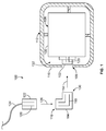
- FIG. 1 is a schematic block diagram of a pass-through connector system 100 formed in accordance with an embodiment.
- the pass-through connector system 100 has a receptacle assembly 102 configured to couple with a pass-through connector 104.
- the receptacle assembly 102 may be mounted to a substrate 106.
- the receptacle assembly 102 may be a header connector assembly.
- the substrate 106 may be a structural component of a device or machine 108.
- the substrate 106 may be a chassis, a block, a frame, a case, and/or the like.
- the device or machine 108 may be or include a motor, an engine, a transmission, a computer, a sensor, and/or the like.
- the device 108 may be an engine, and the substrate 106 is an engine case or block.
- the pass-through connector 104 is configured to extend through a window 109 in a panel 110.
- the panel 110 may be part of a cover 112 that at least partially surrounds the substrate 106 of the device 108.
- the cover 112 may protect the device 108 from encountering debris, liquids, and other contaminants external to the cover 112.
- the cover 112 also may be used as a barrier to maintain internal conditions (e.g., temperature, pressure, gases) within the cover 112 that may differ from ambient external conditions.
- the cover 112 may be mounted or coupled to the substrate 106.
- the cover 112 may be coupled to the substrate 106 separately or independently from the mounting of the receptacle assembly 102 to the substrate 106.
- the cover 112 is shown in cross-section in Figure 1 . It should be noted that Figure 1 is schematic in nature and intended by way of example. In various embodiments, various aspects or structures may be omitted, modified, or added. Further, various devices, systems, or other aspects may be combined. For example, the cover 112 optionally may not surround an entire periphery of the device 108 as is shown in Figure 1 .
- the pass-through connector 104 has a plug end 130 that engages the receptacle assembly 102. To mate with the receptacle assembly 102, the pass-through connector 104 is moved in a mating direction 114 such that the plug end 130 extends through the window 109 of the panel 110. The plug end 130 engages the receptacle assembly 102 in a covered space 132 that is defined between the panel 110 and the substrate 106.
- the pass-through connector 104 includes multiple transition contacts 118, and the receptacle assembly 102 includes multiple receptacle contacts 120.
- the transition contacts 118 engage corresponding receptacle contacts 120 to electrically connect the pass-through connector 104 to the receptacle assembly 102 and provide signal pathways across the panel 110.
- the pass-through connector 104 also has a mating end 116 configured to mate with an auxiliary mating connector 122.
- the auxiliary mating connector 122 shown in Figure 1 is terminated to a cable 124.
- the auxiliary mating connector 122 mates to the pass-through connector 104 in a mating direction 126.
- Mating contacts 128 in the auxiliary mating connector 122 engage the transition contacts 118 of the pass-through connector 104 when the connectors 104, 122 are mated to provide signal pathways through the connectors 104, 122.
- the pass-through connector 104 has two mating interfaces for removably coupling to two different connectors.
- the pass-through connector 104 extends across the panel 110 and provides a transition or intermediary between the receptacle assembly 102 on one side of the panel 110 and the auxiliary mating connector 122 on the other side of the panel 110.
- the connectors 102, 104, 122 provide signal paths that allow sensors and other electrical devices within the panel 110 to communicate with processors, controllers, and other electrical devices remote from the panel 110, such as to relay status information from the device 108 or control orders or power to the device 108.
- the pass-through connector 104 may be terminated directly to a cable, a printed circuit board, or another electrical device.
- FIG. 2 is a front perspective view of the pass-through connector system 100 according to an embodiment showing the pass-through connector 104 poised for mating to the receptacle assembly 102.
- the panel 110 is between the pass-through connector 104 and the receptacle assembly 102.
- the panel 110 has an interior side 134 and an opposite exterior side 136.
- the interior side 134 faces the substrate 106.
- the covered space 132 is defined between the substrate 106 and the interior side 134 of the panel 110.
- the exterior side 136 faces outward away from the substrate 106.
- the window 109 of the panel 110 extends through the panel 110 between the interior and exterior sides 134, 136.
- the panel 110 may be mounted to the substrate 106.
- the receptacle assembly 102 is mounted to the substrate 106 in the covered space 132.
- the receptacle assembly 102 extends between a mating end 138 and a mounting end 140.
- the mating end 138 is configured to engage the pass-through connector 104 during mating.
- the mounting end 140 abuts or is at least proximate to the substrate 106.
- the receptacle assembly 102 includes a mounting ear 142 at or proximate to the mounting end 140.
- the mounting ear 142 is used to mount the receptacle assembly 102 to the substrate 106.
- the mounting ear 142 may receive a fastener 144 that couples the mounting ear 142 to the substrate 106.
- the fastener 144 is a bolt.
- the fastener 144 extends through the mounting ear 142 and into the substrate 106.
- the receptacle assembly 102 may include more than one mounting ear 142 in other embodiments.
- the receptacle assembly 102 is mounted to the substrate 106 separately and independently from the panel 110. Due to separate mountings, it may be difficult to align the mating end 138 with the window 109 of the panel 110 in order to properly align with the pass-through connector 104 that extends through the window 109 during mating.
- the receptacle assembly 102 is radially floatable relative to the substrate such that the receptacle assembly 102 can move to align with the window 109, as described in more detail herein.
- the receptacle assembly 102 includes a base 146 and a receptacle housing 148 that is mounted to the base 146.
- the receptacle housing 148 may be removably coupled to the base 146.
- the receptacle housing 148 may define the mating end 138, and the base 146 may define the mounting end 140.
- the mounting ear 142 may be integral to the base 146.
- the receptacle housing 148 is configured to hold receptacle contacts 120 (shown in Figure 1 ) therein.
- the receptacle contacts 120 terminate to wires 150.
- the wires 150 extend from the receptacle housing 148 through the base 146.
- the wires 150 protrude from an orifice 152 in the base 146.
- the wires 150 extend to sensors, control circuitry, or other electrical devices within the interior of the panel 110.
- the receptacle housing 148 is integral with the base 146 instead of two discrete components.
- the pass-through connector 104 in the unmated position shown in Figure 2 , is entirely outside of the covered space 132.
- the pass-through connector 104 is spaced apart from the exterior side 136 of the panel 110.
- the receptacle assembly 102 on the other hand, is disposed entirely within the covered space 132, and may be spaced apart from the interior side 134 of the panel 110.
- at least a portion of the pass-through connector 104 is loaded through the window 109 from the exterior side 136 towards the interior side 134 and into the covered space 132.
- the portion of the pass-through connector 104 that enters the covered space 132 includes the plug end 130 of the connector 104.
- the plug end 130 engages the mating end 138 of the receptacle assembly 102.
- the pass-through connector 104 engages the receptacle assembly 102 in the covered space 132.
- the mating is a blind mating because it may be impossible or at least difficult for an operator located outside of the panel 110 to visually align the pass-through connector 104 with the receptacle assembly 102 for a coupling that occurs in the covered space 132.
- the pass-through connector 104 has a body 154 that includes at least a first segment 156.
- the first segment 156 extends to and defines the plug end 130. Thus, at least part of the first segment 156 extends through the window 109 and into the covered space 132.
- the pass-through connector 104 includes a compression seal 158 for sealing the body 154 to the panel 110 around the window 109.
- the compression seal 158 may extend around a perimeter of the first segment 156.
- the compression seal 158 is configured to be received between the body 154 and edges 160 of the panel 110 that define the window 109 to seal the body 154 to the panel 110.
- the compression seal 158 may fill gaps between the body 154 and the panel 110 that are present due to the window 109 being slightly larger than a cross-section of the first segment 156 of the body 154.
- the compression seal 158 may also compress in certain areas, applying a biasing force on the body 154 towards a center of the window 109.
- the first segment 156 of the body 154 extends generally along a first axis 162. In the illustrated orientation of the pass-through connector 104 in Figure 2 , the first axis 162 is parallel to the mating direction 114.
- the body 154 further includes a second segment 164.
- the second segment 164 defines the mating end 116 of the pass-through connector 104 that is configured to mate with the auxiliary mating connector 122 (shown in Figure 1 ).
- the second segment 164 extends from the first segment 156 to the mating end 116.
- the second segment 164 extends generally along a second axis 166.
- the first segment 156 is orthogonal or generally or substantially orthogonal to the second segment 164 such that the first and second axes 162, 166 are approximately perpendicular to one another.
- the pass-through connector 104 is a right angle connector. For example, due to space constraints in the surrounding environment outside of the panel 110, it may be easier to mate and un-mate the auxiliary mating connector 122 to and from the pass-through connector 104 in directions that are generally parallel to the exterior side 136 of the panel 110, as opposed to mating perpendicular to the panel 110.
- the window 109 is not large enough to accommodate the second segment 164 of the pass-through connector 104 in the orientation shown in Figure 2 , so a separable interface between the pass-through connector 104 and the receptacle assembly 102 is provided in order to form a right angle signal path that extends through the panel 110.
- the first and second segments 156, 164 of the pass-through connector 104 have other relative angles other than right angles, such as oblique angles or acute angles.
- the pass-through connector 104 includes a shroud 167 at the plug end 130 that is configured to guide the mating end 138 of the receptacle assembly 102 into proper alignment with the pass-through connector 104 during the blind mating process.
- the receptacle assembly 102 is floatable radially relative to the substrate 106, which allows the receptacle assembly 102 to move, at least slightly, in response to the guidance from the shroud 167 to allow the receptacle assembly 102 to properly align with the pass-through connector 104.
- the shroud 167 and/or mating end 138 of the receptacle assembly 102 may be tapered to provide the guidance. Proper alignment between the pass-through connector 104 and the receptacle assembly 102 allows the transition contacts 118 (shown in Figure 1 ) to accurately engage corresponding receptacle contacts 120 ( Figure 1 ) to provide functioning signal paths across the panel 110.
- Figure 3 is a partially-exploded perspective view of the receptacle assembly 102 according to an embodiment.
- the receptacle housing 148 is coupled to the base 146, while the fastener 144 is spaced apart (for example, exploded) from the mounting ear 142.
- the receptacle housing 148 may be formed of an electrically insulating or dielectric material, such as a plastic material.
- the receptacle housing 148 defines multiple ports 178 open at the mating end 138. The ports 178 are configured to house the receptacle contacts 120 (shown in Figure 1 ).
- the receptacle housing 148 may be tapered towards the mating end 138 to facilitate a lead-in surface that is received in the plug end 130 (shown in Figure 2 ) of the pass-through connector 104 during mating.
- a cross-sectional area of the receptacle housing 148 at the mating end 138 may be less than a cross-sectional area of receptacle housing 148 more proximate to the mounting end 140 of the receptacle assembly 102.
- the base 146 optionally may be formed of an electrically insulating or dielectric material, such as plastic. Alternatively, the base 146 may be at least partially composed of a conductive material, such as metal.
- the base 146 optionally may define two different orifices 152 for receiving and directing the wires 150 (shown in Figure 2 ) that terminate to the receptacle contacts 120 ( Figure 1 ) in the receptacle housing 148. The two orifices 152 are located on opposite sides of the base 146.
- the mounting ear 142 has an aperture 168 that extends through the ear 142 between a top 170 and a bottom 172 of the ear 142.
- the aperture 168 is defined by an inner surface 174 of the mounting ear 142.
- the fastener 144 is configured to be received in the aperture 168.
- a diameter of the aperture 168 of the mounting ear 142 is greater than an outer diameter of the fastener 144 such that a gap 220 (shown in Figure 4 ) forms between the inner surface 174 of the mounting ear 142 and an outer surface of the fastener 144.
- the mounting ear 142, and the receptacle assembly 102 in general, is floatable radially within the gap 220 relative to the fastener 144.
- the floatability of the receptacle assembly 102 allows the receptacle assembly 102 to move, at least slightly, as the pass-through connector 104 is mated to the receptacle assembly 102 in order to properly align with the pass-through connector 104.
- the fastener 144 includes a bolt 182 and a bushing 180 that are both received in the aperture 168.
- the bushing 180 defines a channel 184, and the bolt 182 extends through the channel 184 to mechanically engage the substrate 106 (shown in Figure 1 ).
- the bushing 180 surrounds at least a portion of the bolt 182.
- the outer surface 176 of the bushing 180 defines the outer surface of the fastener 144 (and the outer surface of the fastener 144 is referred to herein as "outer surface 176").
- the bushing 180 may be integral to the bolt 182.
- the fastener 144 includes only the bolt 182 and no bushing.
- the bolt 182 is a threaded bolt or screw.
- the bolt 182 may be or include a pin bolt, a rivet, a latch, and/or the like.
- the bolt 182 includes a head 186 and a rod 188 extending from the head 186.
- the rod 188 may be at least partially threaded.
- the mounting ear 142 includes a deflectable finger 190 that extends at least partially into the aperture 168 from the inner surface 174.
- a distal tip 192 of the deflectable finger 190 is configured to engage the fastener 144 to retain the fastener 144 within the aperture 168. The natural resting position of the distal tip 192 is extended into the aperture 168, but the deflectable finger 190 is deflectable outward towards the inner surface 174 of the mounting ear 142, such as when loading the fastener 144 in the aperture 168.
- the mounting ear 142 includes a plurality of deflectable fingers 190 that are dispersed around a perimeter of the inner surface 174. The deflectable fingers 190 may be evenly spaced around the perimeter. Each finger 190 may be independently deflectable.
- the mounting ear 142 may have only a single deflectable finger 190 that optionally extends around an entire perimeter of the inner surface 174.
- the bushing 180 includes a stem 194 that extends between a first flange 196 and a second flange 198.
- the stem 194 bridges the distance between and connects the first and second flanges 196, 198.
- the first and second flanges 196, 198 extend radially outward from the stem 194.
- the channel 184 of the bushing 180 extends through the length of the bushing 180.
- the bushing 180 may be formed of a metal material, a plastic material, or a combination of both.
- the bushing 180 may act as a compression limiter that absorbs compressive forces generated by tightening the bolt 182, thereby reducing the compressive forces applied to the mounting ear 142.
- the bushing 180 is loaded into the aperture 168 of the mounting ear 142.
- the bushing 180 may be loaded from the bottom 172 of the mounting ear 142 towards the top 170 in a loading direction 200.
- the first flange 196 engages the deflectable fingers 190 and deflects the fingers 190 outward.
- the fingers 190 are allowed to return to the natural resting position extended into the aperture 168.
- the bolt 182 is received in the channel 184 of the bushing 180.
- the bolt 182 may be loaded into the channel 184 in an installation direction 202 that extends from the first flange 196 to the second flange 198.
- the installation direction 202 may be opposite to the loading direction 200.
- the bushing 180 is loaded into the aperture 168 of the mounting ear 142 prior to the bolt 182 being installed through the channel 184 of the bushing 180.
- Figure 4 is a cross-sectional view of a portion of the receptacle assembly 102 that includes the mounting ear 142.
- the one or more deflectable fingers 190 may be cantilevered from the inner surface 174 such that each finger 190 has a fixed end 204 at the inner surface 174 and the distal tip 192 at an opposite end.
- the distal tips 192 are located proximate to the top 170 of the mounting ear 142.
- the deflectable fingers 190 may extend both inward (towards the radial center of the aperture 168) and upward towards the top 170.
- the first flange 196 deflects the deflectable fingers 190 radially outward in an arc 191 about the fixed end 204 until the first flange 196 moves beyond the distal tips 192 and the deflectable fingers 190 are allowed to return to the natural resting positions.
- the bushing 180 is fully loaded within the mounting ear 142, such that the deflectable fingers 190 are axially between the first and second flanges 196, 198.
- the bushing 180 is retained within the aperture 168 by the flanges 196, 198 engaging the mounting ear 142.
- an inner surface 206 of the second flange 198 engages the bottom 172 of the mounting ear 142 to limit upward movement of the bushing 180 relative to the mounting ear 142.
- the diameter of the first flange 196 is smaller than the diameter of the aperture 168, while the diameter of the second flange 198 is larger than the diameter of the aperture 168.
- the first flange 196 fits within the aperture 168 when the bushing 180 is being loaded, while the second flange 198 contacts the bottom 172 of the mounting ear 142 and is not permitted into the aperture 168.
- upward movement of the mounting ear 142 relative to the bushing 180 is limited by the distal tips 192 of the deflectable fingers 190 engaging an inner surface 208 of the first flange 196.
- the distal tips 192 extend under the inner surface 208 of the first flange 196 and engage the inner surface 208 to restrict the mounting ear 142 from being pulled upwards off of the fastener 144.
- the inner surfaces 206, 208 of the first and second flanges 196, 198, respectively, are adjacent to the stem 194 and face towards one other.
- the bolt 182 extends through the channel 184 of the bushing 180.
- a distal portion 210 of the rod 188 of the bolt 182 extends beyond the bottom 172 of the mounting ear 142 and beyond the second flange 198 of the bushing 180 to couple to the substrate 106 (shown in Figure 1 ).
- a bottom surface 212 of the head 186 of the bolt 182 may be a bearing surface that engages an outer surface 214 of the first flange 196 to hold the bushing 180 against (or at least proximate to) the substrate 106.
- the bushing 180 may be sandwiched between the substrate 106 and the bottom surface 212 of the head 186, such that the bushing 180 is allowed little to no axial movement relative to the bolt 182.
- a sleeve 216 may be disposed around the rod 188 of the bolt 182.
- the sleeve 216 may be formed of a compressive material, such as rubber or a rubber-like polymer.
- the sleeve 216 is configured to engage an interior surface 218 of the bushing 180 that defines the channel 184.
- the sleeve 216 provides an interference fit between the bolt 182 and the bushing 180 such that the bushing 180 is allowed only negligible radial and/or rotational movement relative to the bolt 182.
- the diameter of the aperture 168 of the mounting ear 142 is greater than the diameter of the outer surface 176 of the fastener 144.
- the diameter of the aperture 168 is greater than the outer diameter of the stem 194 of the bushing 180.
- a gap 220 is formed or defined between the inner surface 174 of the mounting ear 142 and the outer surface 176 of the stem 194.
- the gap 220 has an axial length that extends between the top 170 and the bottom 172 of the mounting ear 142.
- the gap 220 has a radial width that extends between the outer surface 176 of the stem 194 and the inner surface 174 of the mounting ear 142 (including the deflectable fingers 190).
- the width W1 of the gap 220 that is illustrated in Figure 4 represents the radial widths when the bushing 180 and the mounting ear 142 are concentric (for example, share a common axis). In the cross-section shown in Figure 4 , the width W1 of the gap 220 is approximately equal on both sides of the bushing 180.
- the mounting ear 142 of the receptacle assembly 102 (shown in Figure 1 ) is able to float radially within the gap 220 relative to the fastener 144 (for example, relative to both the bolt 182 and the bushing 180).
- the gap 220 has a radial width, so the mounting ear 142 is able to float radially in two dimensions along a plane.
- the mounting ear 142 can float laterally left and right.
- the mounting ear 142 can also float longitudinally frontward and backward relative to the fastener 144, and can float in vectors that have both lateral and longitudinal components.
- the mounting ear 142 may be floatable along the plane defined by lateral and longitudinal axes.
- the mounting ear 142 is not floatable along a vertical (or elevation) axis towards and away from the substrate 106 (shown in Figure 1 ).
- the mounting ear 142 is floatable along the vertical axis, although only for small distances that are less than the available movement along the lateral-longitudinal plane defined by the lateral and longitudinal axes.
- the mounting ear 142 may be floatable along the vertical axis for a distance that is a fraction of the floatable distance along the lateral-longitudinal plane, such as one-fourth or one-tenth.
- the receptacle assembly 102 (including the mounting ear 142) is permitted to float radially relative to the fastener 144 in any radial direction along the lateral-longitudinal plane for a distance that is no more than the width W1.
- the width W1 may be a distance between 0.5 and 3 mm, such as 1 mm or 2 mm, for example.
- the maximum width of the gap 220 on a single side is no more than twice the width W1, which occurs when a portion of the inner surface 174 of the mounting ear 142 engages the outer surface 176 of the fastener 144.
- the receptacle assembly 102 is configured for the mounting ear 142 to be retained between the flanges 196, 198 of the bushing 180 regardless of the radial location of the mounting ear 142 relative to the bushing 180. For example, even when the radial width of the gap 220 is maximized on one side, the mounting ear 142 is prohibited from being pulled upwards out of the bushing 180.
- the stem 194 of the bushing 180 optionally defines a groove 222 that extends along a perimeter of the outer surface 176.
- the groove 222 is located across from the deflectable fingers 190. Since the deflectable fingers 190 extend inward towards the radial center of the aperture 168, the groove 222 reduces the diameter of the stem 194 that is proximate to the fingers 190 to retain the width of the gap 220 between the mounting ear 142 and the stem 194 of the bushing 180.
- the groove 222 may extend from the first flange 196 for a portion of the length of the stem 194 towards the second flange 198.
- the groove 222 may have a slope along the length that complements the deflectable fingers 190, such that the distance between the outer surface 176 of the stem 194 and the mounting ear 142 may be relatively constant in an axial direction between the top 170 and the bottom 172 of the mounting ear 142.
- the diameter of the outer surface 176 is uniform along the length of the stem 194 and does not define the groove 222.
- the radial width of the gap 220 between the distal tips 192 of the deflectable fingers 190 and the stem 194 is less than the radial width of the gap 220 between the fixed ends 204 of the deflectable fingers 190 and the stem 194. But, the distal tips 192 of the deflectable fingers 190 are deflectable outwards, providing additional clearance for the mounting ear 142 to float relative to the bushing 180.
- FIG 5 is a bottom perspective view of the pass-through connector 104 according to an embodiment.
- the pass-through connector 104 may be formed of an electrically insulating or dielectric material, such as a plastic material.
- the pass-through connector 104 defines a cavity 224 that extends between the plug end 130 and the mating end 116.
- the shroud 167 at the plug end 130 defines an opening 226 to the cavity 224.
- the shroud 167 is configured to guide the mating end 138 (shown in Figure 2 ) of the receptacle assembly 102 ( Figure 2 ) into the cavity 224.
- the shroud 167 may include tapered lead-ins 228 that guide the mating end 138 radially towards a center of the cavity 224 in order to properly align with and engage the transition contacts 118 in the pass-through connector 104.
- the shroud 167 is a portion of the first segment 156 of the pass-through connector 104.
- the shroud 167 includes a first side wall 230 and a second side wall 232 that extend to the plug end 130.
- the shroud 167 further includes a first end wall 234 and a second end wall 236 that extend to the plug end 130.
- the end walls 234, 236 extend between and connect the side walls 230, 232.
- the shroud 167 has tapered lead-ins 228 that extend along each of the side walls 230, 232 and along each of the end walls 234, 236.
- the tapered lead-ins 228 extend between a non-tapered portion 238 of the respective walls 230-236 and the plug end 130.
- the tapered lead-ins 228 decrease in thickness in an axial direction from the non-tapered portions 238 towards the plug end 130.
- a cross-sectional area of the cavity 224 defined between the non-tapered portions 238 of the walls 230-236 is less than the cross-sectional area of the cavity 224 in a plane through the tapered lead-ins 228.
- the tapered lead-ins 228 may be located on the side walls 230, 232 only, on the end walls 234, 236 only, or not on any of the walls 230-236 (such as if the mating end 138 of the receptacle assembly 102 is tapered).
- Figure 6 is a cross-sectional view of the pass-through connector system 100 showing the pass-through connector 104 mated to the receptacle assembly 102. Neither the panel 110 (shown in Figure 2 ) nor the substrate 106 ( Figure 2 ) are shown in Figure 6 .
- the plug end 130 of the pass-through connector 104 is loaded through the window 109 (shown in Figure 2 ) of the panel 110 into the covered space 132 ( Figure 2 )
- the plug end 130 engages the mating end 138 of the receptacle assembly 102.
- the plug end 130 may not be properly aligned with the mating end 138 at first engagement.
- the mating end 138 may not properly align with the window 109 of the panel 110.
- the mating between the pass-through connector 104 and the receptacle assembly 102 is blind, so visual alignment may be impossible.
- the shroud 167 or the mating end 138 includes tapered surfaces for guidance.
- the shroud 167 of the pass-through connector 104 includes tapered lead-ins 228 at the plug end 130. As the plug end 130 is loaded onto the mating end 138, the lead-ins 228 guide the mating end 138 into the cavity 224 such that the mating end 138 is centered (or at least in proper alignment so the receptacle contacts 120 (shown in Figure 1 ) engage the corresponding transition contacts 118).
- the gap 220 between the fastener 144 (for example, the bushing 180 of the fastener 144) and the inner surface 174 of the mounting ear 142 allows the receptacle assembly 102 to float radially.
- the receptacle assembly 102 may be floatable radially in a plane that is parallel to a mounting surface of the substrate 106 (shown in Figure 2 ) to which the receptacle assembly 102 is mounted.
- the gap 220 in the mounting ear 142 allows the receptacle assembly 102 to be moved in the direction that the lead-ins 228 guide the mating end 138, such that the mating end 138 properly aligns with the pass-through connector 104.
- the left lead-in 228A forces the mating end 138 to the right as the pass-through connector 104 mates with the receptacle assembly 102.
- the receptacle assembly 102 floats in a rightward direction 240 to accommodate the force applied on the mating end 138 by the lead-in 228A. Since the fastener 144 is fixed in place, as the mounting ear 142 moves in the rightward direction 240 the width of the left gap 220A on the left side of the fastener 144 decreases, while the width of the right gap 220B on the right side of the fastener 144 increases.
- the left and right gaps 220A, 220B are both sections of the gap 220 that extends around the perimeter of the fastener 144. Due to the tapered lead-ins 228 and the floatable receptacle assembly 102, the pass-through connector 104 aligns properly with the receptacle assembly 102 during the blind mating process to provide a signal path across the panel 110.
Landscapes
- Details Of Connecting Devices For Male And Female Coupling (AREA)
Abstract
Description
- The subject matter herein relates generally to connector systems that provide a signal path through a panel. Some known electrical connectors are pass-through connectors that may be used to provide an electrical conductive path through a panel. The panel may be a cover for an electrical device, a machine, or another structure. In an automotive context, the device, machine, or structure may be an engine or a transmission, and the panel may be an engine cover or a transmission cover, respectively. The panel provides protection for the device, machine, structure, and/or the surrounding environment, such as from debris, contaminants, liquids, impact forces, harsh temperatures, or pressures. The panel is typically mounted to (or is otherwise fixed in place relative to) the device, machine, or structure. Yet, sensors and other electrical devices may be located between the panel and the device, machine, or structure. In order to convey signals between the electrical devices within the panel and processors and other devices outside of the panel, conductive paths must be established that extend through an opening in the panel.
- To simplify the passage through the panel versus feeding individual wires through one or more openings in the panel, multiple wires from various internal electrical devices may be terminated to a header connector that is mounted within the panel, on or near the device, machine, or structure. A pass-through connector may be configured to extend through the opening in the panel to mate to the header connector which provides the signal paths across the panel. However, the panel is typically separately mounted to the device, machine, or structure than the header connector, which may cause the header connector to be misaligned relative to the opening of the panel. Since the pass-through connector extends through the opening, the pass-through connector may not align correctly with the header connector, which results in a missed or faulty connection, damage to one or both of the connectors, and/or leaks at the opening that may allow the undesired transmission of contaminants, liquids, debris, pressure, heat, and the like, through the panel. In addition, the header connector is located between the panel and the device, machine, or structure, so the pass-through connector mates blindly to the header connector as the pass-through connector is loaded from outside of the panel through the opening. Thus, it is difficult to properly mate the header connector to the pass-through connector to provide signal paths across the panel because it is difficult to align the opening of the panel with the header connector, and it is difficult to blindly connect the pass-through connector to the header connector. A need remains for a pass-through connector system that provides better alignment and sealing between the connectors and the opening in the panel.
- The solution is provided by a pass-through connector system as disclosed herein that includes a receptacle assembly and a pass-through connector. The receptacle assembly extends between a mating end and a mounting end. The receptacle assembly has a mounting ear at least proximate to the mounting end. The mounting ear defines an aperture therethrough. The receptacle assembly further includes a fastener received in the aperture. The fastener is configured to be coupled to a substrate to mount the receptacle assembly to the substrate. A diameter of the aperture of the mounting ear is greater than an outer diameter of the fastener such that a gap is formed between an inner surface of the mounting ear and an outer surface of the fastener. The pass-through connector has a plug end configured to extend through a window in a panel that at least partially surrounds the substrate to mate to the mating end of the receptacle assembly. The pass-through connector defines a cavity that has an opening at the plug end. The pass-through connector has a shroud at the plug end that guides the mating end of the receptacle assembly through the opening into the cavity. The receptacle assembly is floatable radially within the gap relative to the fastener to allow the shroud of the pass-through connector to move the receptacle assembly into alignment with the cavity of the pass-through connector during mating.
- The invention will now be described by way of example with reference to the accompanying drawings in which:
-
Figure 1 is a schematic block diagram of a pass-through connector system formed in accordance with an embodiment; -
Figure 2 is a front perspective view of the pass-through connector system according to an embodiment showing a pass-through connector poised for mating to a receptacle assembly; -
Figure 3 is a partially-exploded perspective view of the receptacle assembly according to an embodiment; -
Figure 4 is a cross-sectional view of a portion of the receptacle assembly that includes a mounting ear; -
Figure 5 is a bottom perspective view of the pass-through connector according to an embodiment; and -
Figure 6 is a cross-sectional view of the pass-through connector system showing the pass-through connector mated to the receptacle assembly. -
Figure 1 is a schematic block diagram of a pass-throughconnector system 100 formed in accordance with an embodiment. The pass-through connector system 100 has areceptacle assembly 102 configured to couple with a pass-through connector 104. In one or more embodiments, thereceptacle assembly 102 may be mounted to asubstrate 106. Thereceptacle assembly 102 may be a header connector assembly. Thesubstrate 106 may be a structural component of a device or machine 108. For example, thesubstrate 106 may be a chassis, a block, a frame, a case, and/or the like. The device or machine 108 may be or include a motor, an engine, a transmission, a computer, a sensor, and/or the like. In an example, the device 108 may be an engine, and thesubstrate 106 is an engine case or block. - In one or more embodiments, the pass-through
connector 104 is configured to extend through awindow 109 in apanel 110. Thepanel 110 may be part of acover 112 that at least partially surrounds thesubstrate 106 of the device 108. Thecover 112 may protect the device 108 from encountering debris, liquids, and other contaminants external to thecover 112. Thecover 112 also may be used as a barrier to maintain internal conditions (e.g., temperature, pressure, gases) within thecover 112 that may differ from ambient external conditions. Thecover 112 may be mounted or coupled to thesubstrate 106. Optionally, thecover 112 may be coupled to thesubstrate 106 separately or independently from the mounting of thereceptacle assembly 102 to thesubstrate 106. Thecover 112 is shown in cross-section inFigure 1 . It should be noted thatFigure 1 is schematic in nature and intended by way of example. In various embodiments, various aspects or structures may be omitted, modified, or added. Further, various devices, systems, or other aspects may be combined. For example, thecover 112 optionally may not surround an entire periphery of the device 108 as is shown inFigure 1 . - In an embodiment, the pass-
through connector 104 has aplug end 130 that engages thereceptacle assembly 102. To mate with thereceptacle assembly 102, the pass-throughconnector 104 is moved in amating direction 114 such that theplug end 130 extends through thewindow 109 of thepanel 110. Theplug end 130 engages thereceptacle assembly 102 in a coveredspace 132 that is defined between thepanel 110 and thesubstrate 106. The pass-through connector 104 includesmultiple transition contacts 118, and thereceptacle assembly 102 includesmultiple receptacle contacts 120. When the pass-through connector 104 mates to thereceptacle assembly 102, thetransition contacts 118 engagecorresponding receptacle contacts 120 to electrically connect the pass-throughconnector 104 to thereceptacle assembly 102 and provide signal pathways across thepanel 110. - In the illustrated embodiment, the pass-through
connector 104 also has amating end 116 configured to mate with anauxiliary mating connector 122. Theauxiliary mating connector 122 shown inFigure 1 is terminated to acable 124. Theauxiliary mating connector 122 mates to the pass-throughconnector 104 in amating direction 126.Mating contacts 128 in theauxiliary mating connector 122 engage thetransition contacts 118 of the pass-throughconnector 104 when theconnectors connectors - Thus, in the illustrated embodiment, the pass-through
connector 104 has two mating interfaces for removably coupling to two different connectors. For example, the pass-through connector 104 extends across thepanel 110 and provides a transition or intermediary between thereceptacle assembly 102 on one side of thepanel 110 and theauxiliary mating connector 122 on the other side of thepanel 110. Theconnectors panel 110 to communicate with processors, controllers, and other electrical devices remote from thepanel 110, such as to relay status information from the device 108 or control orders or power to the device 108. In an alternative embodiment, the pass-through connector 104 may be terminated directly to a cable, a printed circuit board, or another electrical device. -
Figure 2 is a front perspective view of the pass-throughconnector system 100 according to an embodiment showing the pass-throughconnector 104 poised for mating to thereceptacle assembly 102. Thepanel 110 is between the pass-throughconnector 104 and thereceptacle assembly 102. Thepanel 110 has aninterior side 134 and an oppositeexterior side 136. Theinterior side 134 faces thesubstrate 106. The coveredspace 132 is defined between thesubstrate 106 and theinterior side 134 of thepanel 110. Theexterior side 136 faces outward away from thesubstrate 106. Thewindow 109 of thepanel 110 extends through thepanel 110 between the interior andexterior sides Figure 2 , thepanel 110 may be mounted to thesubstrate 106. - The
receptacle assembly 102 is mounted to thesubstrate 106 in the coveredspace 132. Thereceptacle assembly 102 extends between amating end 138 and a mountingend 140. Themating end 138 is configured to engage the pass-throughconnector 104 during mating. The mountingend 140 abuts or is at least proximate to thesubstrate 106. Thereceptacle assembly 102 includes a mountingear 142 at or proximate to the mountingend 140. The mountingear 142 is used to mount thereceptacle assembly 102 to thesubstrate 106. For example, the mountingear 142 may receive afastener 144 that couples the mountingear 142 to thesubstrate 106. In the illustrated embodiment, thefastener 144 is a bolt. Thefastener 144 extends through the mountingear 142 and into thesubstrate 106. Thereceptacle assembly 102 may include more than one mountingear 142 in other embodiments. Thereceptacle assembly 102 is mounted to thesubstrate 106 separately and independently from thepanel 110. Due to separate mountings, it may be difficult to align themating end 138 with thewindow 109 of thepanel 110 in order to properly align with the pass-throughconnector 104 that extends through thewindow 109 during mating. Thus, in an exemplary embodiment, thereceptacle assembly 102 is radially floatable relative to the substrate such that thereceptacle assembly 102 can move to align with thewindow 109, as described in more detail herein. - In an embodiment, the
receptacle assembly 102 includes abase 146 and areceptacle housing 148 that is mounted to thebase 146. Thereceptacle housing 148 may be removably coupled to thebase 146. Thereceptacle housing 148 may define themating end 138, and the base 146 may define the mountingend 140. The mountingear 142 may be integral to thebase 146. Thereceptacle housing 148 is configured to hold receptacle contacts 120 (shown inFigure 1 ) therein. Thereceptacle contacts 120 terminate towires 150. Thewires 150 extend from thereceptacle housing 148 through thebase 146. Thewires 150 protrude from anorifice 152 in thebase 146. Thewires 150 extend to sensors, control circuitry, or other electrical devices within the interior of thepanel 110. In an alternative embodiment, thereceptacle housing 148 is integral with the base 146 instead of two discrete components. - The pass-through
connector 104, in the unmated position shown inFigure 2 , is entirely outside of the coveredspace 132. The pass-throughconnector 104 is spaced apart from theexterior side 136 of thepanel 110. Thereceptacle assembly 102, on the other hand, is disposed entirely within the coveredspace 132, and may be spaced apart from theinterior side 134 of thepanel 110. In an embodiment, to mate the pass-throughconnector 104 to thereceptacle assembly 102, at least a portion of the pass-throughconnector 104 is loaded through thewindow 109 from theexterior side 136 towards theinterior side 134 and into the coveredspace 132. In an embodiment, the portion of the pass-throughconnector 104 that enters the coveredspace 132 includes theplug end 130 of theconnector 104. Theplug end 130 engages themating end 138 of thereceptacle assembly 102. Thus, the pass-throughconnector 104 engages thereceptacle assembly 102 in the coveredspace 132. The mating is a blind mating because it may be impossible or at least difficult for an operator located outside of thepanel 110 to visually align the pass-throughconnector 104 with thereceptacle assembly 102 for a coupling that occurs in the coveredspace 132. - The pass-through
connector 104 has abody 154 that includes at least afirst segment 156. Thefirst segment 156 extends to and defines theplug end 130. Thus, at least part of thefirst segment 156 extends through thewindow 109 and into the coveredspace 132. In an embodiment, the pass-throughconnector 104 includes acompression seal 158 for sealing thebody 154 to thepanel 110 around thewindow 109. For example, thecompression seal 158 may extend around a perimeter of thefirst segment 156. Thecompression seal 158 is configured to be received between thebody 154 andedges 160 of thepanel 110 that define thewindow 109 to seal thebody 154 to thepanel 110. For example, thecompression seal 158 may fill gaps between thebody 154 and thepanel 110 that are present due to thewindow 109 being slightly larger than a cross-section of thefirst segment 156 of thebody 154. Thecompression seal 158 may also compress in certain areas, applying a biasing force on thebody 154 towards a center of thewindow 109. - In an embodiment, the
first segment 156 of thebody 154 extends generally along afirst axis 162. In the illustrated orientation of the pass-throughconnector 104 inFigure 2 , thefirst axis 162 is parallel to themating direction 114. In an exemplary embodiment, thebody 154 further includes asecond segment 164. Thesecond segment 164 defines themating end 116 of the pass-throughconnector 104 that is configured to mate with the auxiliary mating connector 122 (shown inFigure 1 ). Thesecond segment 164 extends from thefirst segment 156 to themating end 116. Thesecond segment 164 extends generally along asecond axis 166. In the illustrated embodiment, thefirst segment 156 is orthogonal or generally or substantially orthogonal to thesecond segment 164 such that the first andsecond axes connector 104 is a right angle connector. For example, due to space constraints in the surrounding environment outside of thepanel 110, it may be easier to mate and un-mate theauxiliary mating connector 122 to and from the pass-throughconnector 104 in directions that are generally parallel to theexterior side 136 of thepanel 110, as opposed to mating perpendicular to thepanel 110. Thewindow 109 is not large enough to accommodate thesecond segment 164 of the pass-throughconnector 104 in the orientation shown inFigure 2 , so a separable interface between the pass-throughconnector 104 and thereceptacle assembly 102 is provided in order to form a right angle signal path that extends through thepanel 110. In other embodiments, the first andsecond segments connector 104 have other relative angles other than right angles, such as oblique angles or acute angles. - As described further herein, the pass-through
connector 104 includes ashroud 167 at theplug end 130 that is configured to guide themating end 138 of thereceptacle assembly 102 into proper alignment with the pass-throughconnector 104 during the blind mating process. Thereceptacle assembly 102 is floatable radially relative to thesubstrate 106, which allows thereceptacle assembly 102 to move, at least slightly, in response to the guidance from theshroud 167 to allow thereceptacle assembly 102 to properly align with the pass-throughconnector 104. Optionally, theshroud 167 and/ormating end 138 of thereceptacle assembly 102 may be tapered to provide the guidance. Proper alignment between the pass-throughconnector 104 and thereceptacle assembly 102 allows the transition contacts 118 (shown inFigure 1 ) to accurately engage corresponding receptacle contacts 120 (Figure 1 ) to provide functioning signal paths across thepanel 110. -
Figure 3 is a partially-exploded perspective view of thereceptacle assembly 102 according to an embodiment. InFigure 3 , thereceptacle housing 148 is coupled to thebase 146, while thefastener 144 is spaced apart (for example, exploded) from the mountingear 142. Thereceptacle housing 148 may be formed of an electrically insulating or dielectric material, such as a plastic material. Thereceptacle housing 148 definesmultiple ports 178 open at themating end 138. Theports 178 are configured to house the receptacle contacts 120 (shown inFigure 1 ). Although not shown inFigure 3 , thereceptacle housing 148 may be tapered towards themating end 138 to facilitate a lead-in surface that is received in the plug end 130 (shown inFigure 2 ) of the pass-throughconnector 104 during mating. For example, a cross-sectional area of thereceptacle housing 148 at themating end 138 may be less than a cross-sectional area ofreceptacle housing 148 more proximate to the mountingend 140 of thereceptacle assembly 102. - The base 146 optionally may be formed of an electrically insulating or dielectric material, such as plastic. Alternatively, the
base 146 may be at least partially composed of a conductive material, such as metal. The base 146 optionally may define twodifferent orifices 152 for receiving and directing the wires 150 (shown inFigure 2 ) that terminate to the receptacle contacts 120 (Figure 1 ) in thereceptacle housing 148. The twoorifices 152 are located on opposite sides of thebase 146. - The mounting
ear 142 has anaperture 168 that extends through theear 142 between a top 170 and abottom 172 of theear 142. Theaperture 168 is defined by aninner surface 174 of the mountingear 142. Thefastener 144 is configured to be received in theaperture 168. In an embodiment, a diameter of theaperture 168 of the mountingear 142 is greater than an outer diameter of thefastener 144 such that a gap 220 (shown inFigure 4 ) forms between theinner surface 174 of the mountingear 142 and an outer surface of thefastener 144. When thefastener 144 is coupled to the substrate 106 (shown inFigure 1 ), thefastener 144 is fixed in place. The mountingear 142, and thereceptacle assembly 102 in general, is floatable radially within thegap 220 relative to thefastener 144. The floatability of thereceptacle assembly 102 allows thereceptacle assembly 102 to move, at least slightly, as the pass-throughconnector 104 is mated to thereceptacle assembly 102 in order to properly align with the pass-throughconnector 104. - In an embodiment, the
fastener 144 includes abolt 182 and abushing 180 that are both received in theaperture 168. Thebushing 180 defines achannel 184, and thebolt 182 extends through thechannel 184 to mechanically engage the substrate 106 (shown inFigure 1 ). Thus, thebushing 180 surrounds at least a portion of thebolt 182. Theouter surface 176 of thebushing 180 defines the outer surface of the fastener 144 (and the outer surface of thefastener 144 is referred to herein as "outer surface 176"). In an alternative embodiment, thebushing 180 may be integral to thebolt 182. In another alternative embodiment, thefastener 144 includes only thebolt 182 and no bushing. In the illustrated embodiment, thebolt 182 is a threaded bolt or screw. In alternative embodiments, thebolt 182 may be or include a pin bolt, a rivet, a latch, and/or the like. Thebolt 182 includes ahead 186 and arod 188 extending from thehead 186. Therod 188 may be at least partially threaded. - The mounting
ear 142 includes adeflectable finger 190 that extends at least partially into theaperture 168 from theinner surface 174. Adistal tip 192 of thedeflectable finger 190 is configured to engage thefastener 144 to retain thefastener 144 within theaperture 168. The natural resting position of thedistal tip 192 is extended into theaperture 168, but thedeflectable finger 190 is deflectable outward towards theinner surface 174 of the mountingear 142, such as when loading thefastener 144 in theaperture 168. In the illustrated embodiment, the mountingear 142 includes a plurality ofdeflectable fingers 190 that are dispersed around a perimeter of theinner surface 174. Thedeflectable fingers 190 may be evenly spaced around the perimeter. Eachfinger 190 may be independently deflectable. In an alternative embodiment, the mountingear 142 may have only a singledeflectable finger 190 that optionally extends around an entire perimeter of theinner surface 174. - In an embodiment, the
bushing 180 includes astem 194 that extends between afirst flange 196 and asecond flange 198. For example, thestem 194 bridges the distance between and connects the first andsecond flanges second flanges stem 194. Thechannel 184 of thebushing 180 extends through the length of thebushing 180. Thebushing 180 may be formed of a metal material, a plastic material, or a combination of both. Thebushing 180 may act as a compression limiter that absorbs compressive forces generated by tightening thebolt 182, thereby reducing the compressive forces applied to the mountingear 142. - To assemble the
receptacle assembly 102, thebushing 180 is loaded into theaperture 168 of the mountingear 142. For example, thebushing 180 may be loaded from thebottom 172 of the mountingear 142 towards the top 170 in aloading direction 200. As thebushing 180 is loaded, thefirst flange 196 engages thedeflectable fingers 190 and deflects thefingers 190 outward. When thefirst flange 196 moves beyond (e.g., past) thefingers 190 in theloading direction 200, thefingers 190 are allowed to return to the natural resting position extended into theaperture 168. Thebolt 182 is received in thechannel 184 of thebushing 180. For example, thebolt 182 may be loaded into thechannel 184 in aninstallation direction 202 that extends from thefirst flange 196 to thesecond flange 198. Theinstallation direction 202 may be opposite to theloading direction 200. Optionally, thebushing 180 is loaded into theaperture 168 of the mountingear 142 prior to thebolt 182 being installed through thechannel 184 of thebushing 180. -
Figure 4 is a cross-sectional view of a portion of thereceptacle assembly 102 that includes the mountingear 142. The one or moredeflectable fingers 190 may be cantilevered from theinner surface 174 such that eachfinger 190 has a fixedend 204 at theinner surface 174 and thedistal tip 192 at an opposite end. In an embodiment, thedistal tips 192 are located proximate to the top 170 of the mountingear 142. For example, thedeflectable fingers 190 may extend both inward (towards the radial center of the aperture 168) and upward towards the top 170. When thebushing 180 is being loaded upwards in the loading direction 200 (shown inFigure 3 ), thefirst flange 196 deflects thedeflectable fingers 190 radially outward in anarc 191 about thefixed end 204 until thefirst flange 196 moves beyond thedistal tips 192 and thedeflectable fingers 190 are allowed to return to the natural resting positions. InFigure 4 , thebushing 180 is fully loaded within the mountingear 142, such that thedeflectable fingers 190 are axially between the first andsecond flanges - The
bushing 180 is retained within theaperture 168 by theflanges ear 142. For example, aninner surface 206 of thesecond flange 198 engages the bottom 172 of the mountingear 142 to limit upward movement of thebushing 180 relative to the mountingear 142. In an embodiment, the diameter of thefirst flange 196 is smaller than the diameter of theaperture 168, while the diameter of thesecond flange 198 is larger than the diameter of theaperture 168. Thus, thefirst flange 196 fits within theaperture 168 when thebushing 180 is being loaded, while thesecond flange 198 contacts thebottom 172 of the mountingear 142 and is not permitted into theaperture 168. In an embodiment, upward movement of the mountingear 142 relative to thebushing 180 is limited by thedistal tips 192 of thedeflectable fingers 190 engaging aninner surface 208 of thefirst flange 196. For example, when thedeflectable fingers 190 are in the natural resting position, thedistal tips 192 extend under theinner surface 208 of thefirst flange 196 and engage theinner surface 208 to restrict the mountingear 142 from being pulled upwards off of thefastener 144. Theinner surfaces second flanges stem 194 and face towards one other. - The
bolt 182 extends through thechannel 184 of thebushing 180. Adistal portion 210 of therod 188 of thebolt 182 extends beyond thebottom 172 of the mountingear 142 and beyond thesecond flange 198 of thebushing 180 to couple to the substrate 106 (shown inFigure 1 ). Abottom surface 212 of thehead 186 of thebolt 182 may be a bearing surface that engages anouter surface 214 of thefirst flange 196 to hold thebushing 180 against (or at least proximate to) thesubstrate 106. Thus, thebushing 180 may be sandwiched between thesubstrate 106 and thebottom surface 212 of thehead 186, such that thebushing 180 is allowed little to no axial movement relative to thebolt 182. Optionally, asleeve 216 may be disposed around therod 188 of thebolt 182. Thesleeve 216 may be formed of a compressive material, such as rubber or a rubber-like polymer. Thesleeve 216 is configured to engage aninterior surface 218 of thebushing 180 that defines thechannel 184. In an embodiment, thesleeve 216 provides an interference fit between thebolt 182 and thebushing 180 such that thebushing 180 is allowed only negligible radial and/or rotational movement relative to thebolt 182. - In an exemplary embodiment, the diameter of the
aperture 168 of the mountingear 142 is greater than the diameter of theouter surface 176 of thefastener 144. For example, the diameter of theaperture 168 is greater than the outer diameter of thestem 194 of thebushing 180. As a result, agap 220 is formed or defined between theinner surface 174 of the mountingear 142 and theouter surface 176 of thestem 194. Thegap 220 has an axial length that extends between the top 170 and thebottom 172 of the mountingear 142. Thegap 220 has a radial width that extends between theouter surface 176 of thestem 194 and theinner surface 174 of the mounting ear 142 (including the deflectable fingers 190). For example, the width W1 of thegap 220 that is illustrated inFigure 4 represents the radial widths when thebushing 180 and the mountingear 142 are concentric (for example, share a common axis). In the cross-section shown inFigure 4 , the width W1 of thegap 220 is approximately equal on both sides of thebushing 180. - The mounting
ear 142 of the receptacle assembly 102 (shown inFigure 1 ) is able to float radially within thegap 220 relative to the fastener 144 (for example, relative to both thebolt 182 and the bushing 180). Thegap 220 has a radial width, so the mountingear 142 is able to float radially in two dimensions along a plane. For example, in the cross-section shown inFigure 4 , the mountingear 142 can float laterally left and right. Although not shown inFigure 4 , the mountingear 142 can also float longitudinally frontward and backward relative to thefastener 144, and can float in vectors that have both lateral and longitudinal components. Thus, the mountingear 142 may be floatable along the plane defined by lateral and longitudinal axes. Optionally, the mountingear 142 is not floatable along a vertical (or elevation) axis towards and away from the substrate 106 (shown inFigure 1 ). Optionally, the mountingear 142 is floatable along the vertical axis, although only for small distances that are less than the available movement along the lateral-longitudinal plane defined by the lateral and longitudinal axes. For example, the mountingear 142 may be floatable along the vertical axis for a distance that is a fraction of the floatable distance along the lateral-longitudinal plane, such as one-fourth or one-tenth. - From the position shown in
Figure 4 , the receptacle assembly 102 (including the mounting ear 142) is permitted to float radially relative to thefastener 144 in any radial direction along the lateral-longitudinal plane for a distance that is no more than the width W1. Optionally, the width W1 may be a distance between 0.5 and 3 mm, such as 1 mm or 2 mm, for example. The maximum width of thegap 220 on a single side is no more than twice the width W1, which occurs when a portion of theinner surface 174 of the mountingear 142 engages theouter surface 176 of thefastener 144. Thereceptacle assembly 102 is configured for the mountingear 142 to be retained between theflanges bushing 180 regardless of the radial location of the mountingear 142 relative to thebushing 180. For example, even when the radial width of thegap 220 is maximized on one side, the mountingear 142 is prohibited from being pulled upwards out of thebushing 180. - The
stem 194 of thebushing 180 optionally defines agroove 222 that extends along a perimeter of theouter surface 176. Thegroove 222 is located across from thedeflectable fingers 190. Since thedeflectable fingers 190 extend inward towards the radial center of theaperture 168, thegroove 222 reduces the diameter of thestem 194 that is proximate to thefingers 190 to retain the width of thegap 220 between the mountingear 142 and thestem 194 of thebushing 180. Thegroove 222 may extend from thefirst flange 196 for a portion of the length of thestem 194 towards thesecond flange 198. Although not shown inFigure 4 , thegroove 222 may have a slope along the length that complements thedeflectable fingers 190, such that the distance between theouter surface 176 of thestem 194 and the mountingear 142 may be relatively constant in an axial direction between the top 170 and thebottom 172 of the mountingear 142. In an alternative embodiment, the diameter of theouter surface 176 is uniform along the length of thestem 194 and does not define thegroove 222. In this alternative embodiment, the radial width of thegap 220 between thedistal tips 192 of thedeflectable fingers 190 and thestem 194 is less than the radial width of thegap 220 between the fixed ends 204 of thedeflectable fingers 190 and thestem 194. But, thedistal tips 192 of thedeflectable fingers 190 are deflectable outwards, providing additional clearance for the mountingear 142 to float relative to thebushing 180. -
Figure 5 is a bottom perspective view of the pass-throughconnector 104 according to an embodiment. The pass-throughconnector 104 may be formed of an electrically insulating or dielectric material, such as a plastic material. The pass-throughconnector 104 defines acavity 224 that extends between theplug end 130 and themating end 116. Theshroud 167 at theplug end 130 defines anopening 226 to thecavity 224. In an embodiment, theshroud 167 is configured to guide the mating end 138 (shown inFigure 2 ) of the receptacle assembly 102 (Figure 2 ) into thecavity 224. For example, theshroud 167 may include tapered lead-ins 228 that guide themating end 138 radially towards a center of thecavity 224 in order to properly align with and engage thetransition contacts 118 in the pass-throughconnector 104. - The
shroud 167 is a portion of thefirst segment 156 of the pass-throughconnector 104. Theshroud 167 includes afirst side wall 230 and asecond side wall 232 that extend to theplug end 130. Theshroud 167 further includes afirst end wall 234 and asecond end wall 236 that extend to theplug end 130. Theend walls side walls shroud 167 has tapered lead-ins 228 that extend along each of theside walls end walls ins 228 extend between anon-tapered portion 238 of the respective walls 230-236 and theplug end 130. The tapered lead-ins 228 decrease in thickness in an axial direction from thenon-tapered portions 238 towards theplug end 130. For example, a cross-sectional area of thecavity 224 defined between thenon-tapered portions 238 of the walls 230-236 is less than the cross-sectional area of thecavity 224 in a plane through the tapered lead-ins 228. In alternative embodiments, the tapered lead-ins 228 may be located on theside walls end walls mating end 138 of thereceptacle assembly 102 is tapered). -
Figure 6 is a cross-sectional view of the pass-throughconnector system 100 showing the pass-throughconnector 104 mated to thereceptacle assembly 102. Neither the panel 110 (shown inFigure 2 ) nor the substrate 106 (Figure 2 ) are shown inFigure 6 . During mating, when theplug end 130 of the pass-throughconnector 104 is loaded through the window 109 (shown inFigure 2 ) of thepanel 110 into the covered space 132 (Figure 2 ), theplug end 130 engages themating end 138 of thereceptacle assembly 102. Theplug end 130 may not be properly aligned with themating end 138 at first engagement. For example, since thereceptacle assembly 102 may not be directly coupled to thepanel 110, and thereceptacle assembly 102 and thepanel 110 may be separately mounted to thesubstrate 106, themating end 138 may not properly align with thewindow 109 of thepanel 110. In addition, the mating between the pass-throughconnector 104 and thereceptacle assembly 102 is blind, so visual alignment may be impossible. - In an exemplary embodiment, at least one of the
shroud 167 or themating end 138 includes tapered surfaces for guidance. In the illustrated embodiment, theshroud 167 of the pass-throughconnector 104 includes tapered lead-ins 228 at theplug end 130. As theplug end 130 is loaded onto themating end 138, the lead-ins 228 guide themating end 138 into thecavity 224 such that themating end 138 is centered (or at least in proper alignment so the receptacle contacts 120 (shown inFigure 1 ) engage the corresponding transition contacts 118). Thegap 220 between the fastener 144 (for example, thebushing 180 of the fastener 144) and theinner surface 174 of the mountingear 142 allows thereceptacle assembly 102 to float radially. For example, thereceptacle assembly 102 may be floatable radially in a plane that is parallel to a mounting surface of the substrate 106 (shown inFigure 2 ) to which thereceptacle assembly 102 is mounted. Thus, as themating end 138 of thereceptacle assembly 102 engages the lead-ins 228 of the pass-throughconnector 104, thegap 220 in the mountingear 142 allows thereceptacle assembly 102 to be moved in the direction that the lead-ins 228 guide themating end 138, such that themating end 138 properly aligns with the pass-throughconnector 104. - For example, if the
mating end 138 is misaligned and too far to the left upon engaging theplug end 130 of the pass-throughconnector 104, the left lead-in 228A forces themating end 138 to the right as the pass-throughconnector 104 mates with thereceptacle assembly 102. Thereceptacle assembly 102 floats in arightward direction 240 to accommodate the force applied on themating end 138 by the lead-in 228A. Since thefastener 144 is fixed in place, as the mountingear 142 moves in therightward direction 240 the width of theleft gap 220A on the left side of thefastener 144 decreases, while the width of theright gap 220B on the right side of thefastener 144 increases. The left andright gaps gap 220 that extends around the perimeter of thefastener 144. Due to the tapered lead-ins 228 and thefloatable receptacle assembly 102, the pass-throughconnector 104 aligns properly with thereceptacle assembly 102 during the blind mating process to provide a signal path across thepanel 110. - It is to be understood that the above description is intended to be illustrative, and not restrictive. For example, the above-described embodiments (and/or aspects thereof) may be used in combination with each other. In addition, many modifications may be made to adapt a particular situation or material to the teachings of the invention without departing from its scope. Dimensions, types of materials, orientations of the various components, and the number and positions of the various components described herein are intended to define parameters of certain embodiments, and are by no means limiting and are merely exemplary embodiments. Many other embodiments and modifications within the scope of the claims will be apparent to those of skill in the art upon reviewing the above description. The scope of the invention should, therefore, be determined with reference to the appended claims.
Claims (10)
- A pass-through connector system (100) comprising:a receptacle assembly (102) extending between a mating end (138) and a mounting end (140), the receptacle assembly having a mounting ear (142) at least proximate to the mounting end, the mounting ear defining an aperture (168) therethrough, the receptacle assembly further including a fastener (144) received in the aperture that is configured to be coupled to a substrate (106) to mount the receptacle assembly to the substrate, a diameter of the aperture of the mounting ear being greater than an outer diameter of the fastener such that a gap (220) is formed between an inner surface (174) of the mounting ear and an outer surface (176) of the fastener; anda pass-through connector (104) having a plug end (130) configured to extend through a window (109) in a panel (110) that at least partially surrounds the substrate to mate to the mating end of the receptacle assembly, the pass-through connector defining a cavity (224) that has an opening (226) at the plug end, the pass-through connector having a shroud (167) at the plug end that guides the mating end of the receptacle assembly through the opening into the cavity;wherein the receptacle assembly is floatable radially within the gap relative to the fastener to allow the shroud of the pass-through connector to move the receptacle assembly into alignment with the cavity of the pass-through connector during mating.
- The pass-through connector system (100) of claim 1, wherein the receptacle assembly (102) is mounted to the substrate (106) and located in a covered space (132) between the substrate and an interior side (134) of the panel (110), at least a portion of the pass-through connector (104) extending through the window (109) from an exterior side (136) of the panel such that the plug end (130) of the pass-through connector mates to the receptacle assembly in the covered space.
- The pass-through connector system (100) of claim 1 or 2, wherein the pass-through connector (104) has a body (154) including a first segment (156) that extends to the plug end (130) and a second segment (164) that extends to a mating end (116) configured to mate with an auxiliary mating connector (122), the first segment extending substantially orthogonal to the second segment.
- The pass-through connector system (100) of claim 1 or 2, wherein the pass-through connector (104) has a body (154) including at least a first segment (156), the first segment extending to the plug end (130), the pass-through connector including a compression seal (158) disposed around a perimeter of the first segment, the compression seal being disposed between the body and edges (160) of the panel (110) defining the window (109) and configured to seal the pass-through connector to the panel.
- The pass-through connector system (100) of any preceding claim, wherein the receptacle assembly (102) includes a base (146) and a receptacle housing (148) mounted to the base, the mounting ear (142) being integral to the base, the receptacle housing holding receptacle contacts (120) therein, the receptacle contacts terminating to wires (150), the wires extending from the receptacle housing through the base and protruding from an orifice (152) in the base.
- The pass-through connector system (100) of any preceding claim, wherein the mounting ear (142) includes a plurality of deflectable fingers (190) dispersed around a perimeter of the inner surface (174) that defines the aperture (168), the deflectable fingers extending into the aperture from the inner surface, distal tips (192) of the deflectable fingers configured to engage a flange (196) of the fastener (144) to retain the fastener within the aperture.
- The pass-through connector system (100) of any one of claims 1 to 5, wherein the fastener (144) comprises a bolt (182) and a bushing (180) that surrounds the bolt, the bushing having a stem (194) defined between a first flange (196) and a second flange (198), the first and second flanges extending radially outward from the stem, the first flange configured to engage at least one deflectable finger (190) of the mounting ear (142) that extends into the aperture (168) and the second flange configured to engage a bottom (172) of the mounting ear to retain the bushing in the aperture.
- The pass-through connector system (100) of any preceding claim, wherein the shroud (167) of the pass-through connector (104) has first and second side walls (230, 232) and first and second end walls (234, 236) that extend between the first and second side walls, the shroud including tapered lead-ins (228) at the plug end (130) that extend along each of the first and second side walls and the first and second end walls to guide the mating end (138) of the receptacle assembly (102) radially towards a center of the cavity (224) during mating.
- The pass-through connector system (100) of any preceding claim, wherein the receptacle assembly (102) is radially floatable in two dimensions along a plane.
- The pass-through connector system (100) of any preceding claim, wherein the receptacle assembly (102) is tapered towards the mating end (138) such that a cross-sectional area of the receptacle assembly at the mating end is less than a cross-sectional area of the receptacle assembly more proximate to the mounting end (140).
Applications Claiming Priority (1)
| Application Number | Priority Date | Filing Date | Title |
|---|---|---|---|
| US14/675,033 US9270052B1 (en) | 2015-03-31 | 2015-03-31 | Pass-through connector system |
Publications (2)
| Publication Number | Publication Date |
|---|---|
| EP3076494A1 true EP3076494A1 (en) | 2016-10-05 |
| EP3076494B1 EP3076494B1 (en) | 2018-08-29 |
Family
ID=55314758
Family Applications (1)
| Application Number | Title | Priority Date | Filing Date |
|---|---|---|---|
| EP16162791.4A Not-in-force EP3076494B1 (en) | 2015-03-31 | 2016-03-30 | Pass-through connector system |
Country Status (3)
| Country | Link |
|---|---|
| US (1) | US9270052B1 (en) |
| EP (1) | EP3076494B1 (en) |
| CN (1) | CN106025661B (en) |
Cited By (1)
| Publication number | Priority date | Publication date | Assignee | Title |
|---|---|---|---|---|
| EP3809531A1 (en) | 2019-10-15 | 2021-04-21 | Hirose Electric Co., Ltd. | Connector assembly for in-vehicle equipment and method |
Families Citing this family (12)
| Publication number | Priority date | Publication date | Assignee | Title |
|---|---|---|---|---|
| JP6593651B2 (en) * | 2016-05-23 | 2019-10-23 | 住友電装株式会社 | connector |
| CN108075291B (en) * | 2016-11-11 | 2020-06-05 | 莫列斯有限公司 | Electrical Connectors and Terminals |
| DE102017126477A1 (en) * | 2017-11-10 | 2019-05-16 | Syn Trac Gmbh | clutch plate |
| US11404803B2 (en) | 2018-05-17 | 2022-08-02 | Dresser-Rand Company | Electrical connector having a staggered contact carrier |
| KR102767932B1 (en) * | 2019-10-17 | 2025-02-18 | 타이코에이엠피 주식회사 | Connector assembly and method of manufacturing the same |
| US11258216B2 (en) * | 2019-12-06 | 2022-02-22 | TE Connectivity Services Gmbh | Floatable connector and wire harness tray |
| JP7271499B2 (en) * | 2020-12-21 | 2023-05-11 | プライムプラネットエナジー&ソリューションズ株式会社 | storage module |
| DE102021105914A1 (en) * | 2021-03-11 | 2022-09-15 | Marquardt Gmbh | High-voltage management system, especially for vehicle energy storage |
| US11949189B2 (en) * | 2021-08-17 | 2024-04-02 | Te Connectivity Solutions Gmbh | Circuit board assembly for a communication system |
| US11923638B2 (en) * | 2021-11-02 | 2024-03-05 | Te Connectivity Solutions Gmbh | Circuit board assembly for a communication system |
| KR102676509B1 (en) * | 2021-12-29 | 2024-06-19 | 주식회사 유라 | Connector for drive motor |
| US12424780B2 (en) * | 2023-05-26 | 2025-09-23 | Te Connectivity Solutions Gmbh | Power harness |
Citations (6)
| Publication number | Priority date | Publication date | Assignee | Title |
|---|---|---|---|---|
| US5002497A (en) * | 1990-01-26 | 1991-03-26 | Molex Incorporated | Floatable panel mountable electrical connector assembly |
| US5383790A (en) * | 1993-11-19 | 1995-01-24 | G & H Technology, Inc. | Connector with floating self-alignment and zero impulse separation mechanisms |
| US6089910A (en) * | 1998-02-18 | 2000-07-18 | Yazaki Corporation | Connection structure of movable connector |
| US6234817B1 (en) * | 1999-04-29 | 2001-05-22 | Hon Hai Precision Ind. Co., Ltd. | Blind-mate, floatable connectors assembly |
| DE102010022987A1 (en) * | 2010-06-08 | 2011-12-08 | Phoenix Contact Gmbh & Co. Kg | Electrical device with a connector and electrical connector |
| WO2013094774A1 (en) * | 2011-12-22 | 2013-06-27 | Yazaki Corporation | Waterproof connector connection structure |
Family Cites Families (7)
| Publication number | Priority date | Publication date | Assignee | Title |
|---|---|---|---|---|
| US5127852A (en) * | 1990-10-24 | 1992-07-07 | Amp Incorporated | Mounting device for electrical connectors |
| TW321377U (en) * | 1996-10-18 | 1997-11-21 | Hon Hai Prec Ind Co Ltd | Fastener of electrical connector |
| US6312285B1 (en) * | 1999-02-25 | 2001-11-06 | Molex Incorporated | Panel mounting system for electrical connectors |
| US7758369B2 (en) * | 2008-04-25 | 2010-07-20 | Tyco Electronics Corporation | Plug connector for use with a receptacle |
| US7878844B2 (en) * | 2009-01-08 | 2011-02-01 | Tyco Electronics Corporation | Panel connector assembly |
| CN102738647B (en) * | 2011-04-01 | 2015-04-01 | 鸿富锦精密工业(深圳)有限公司 | Connector assembly |
| US8672708B2 (en) * | 2012-07-09 | 2014-03-18 | Tyco Electronics Corporation | Connector assembly having a floatable module assembly with a coupling member |
-
2015
- 2015-03-31 US US14/675,033 patent/US9270052B1/en active Active
-
2016
- 2016-03-30 CN CN201610192694.2A patent/CN106025661B/en not_active Expired - Fee Related
- 2016-03-30 EP EP16162791.4A patent/EP3076494B1/en not_active Not-in-force
Patent Citations (6)
| Publication number | Priority date | Publication date | Assignee | Title |
|---|---|---|---|---|
| US5002497A (en) * | 1990-01-26 | 1991-03-26 | Molex Incorporated | Floatable panel mountable electrical connector assembly |
| US5383790A (en) * | 1993-11-19 | 1995-01-24 | G & H Technology, Inc. | Connector with floating self-alignment and zero impulse separation mechanisms |
| US6089910A (en) * | 1998-02-18 | 2000-07-18 | Yazaki Corporation | Connection structure of movable connector |
| US6234817B1 (en) * | 1999-04-29 | 2001-05-22 | Hon Hai Precision Ind. Co., Ltd. | Blind-mate, floatable connectors assembly |
| DE102010022987A1 (en) * | 2010-06-08 | 2011-12-08 | Phoenix Contact Gmbh & Co. Kg | Electrical device with a connector and electrical connector |
| WO2013094774A1 (en) * | 2011-12-22 | 2013-06-27 | Yazaki Corporation | Waterproof connector connection structure |
Cited By (1)
| Publication number | Priority date | Publication date | Assignee | Title |
|---|---|---|---|---|
| EP3809531A1 (en) | 2019-10-15 | 2021-04-21 | Hirose Electric Co., Ltd. | Connector assembly for in-vehicle equipment and method |
Also Published As
| Publication number | Publication date |
|---|---|
| EP3076494B1 (en) | 2018-08-29 |
| CN106025661A (en) | 2016-10-12 |
| CN106025661B (en) | 2020-05-05 |
| US9270052B1 (en) | 2016-02-23 |
Similar Documents
| Publication | Publication Date | Title |
|---|---|---|
| EP3076494B1 (en) | Pass-through connector system | |
| EP3076495B1 (en) | Floatable connector | |
| CN105191007B (en) | Angle coupling component | |
| US10892584B2 (en) | Socket-shaped housing, connector, and connector arrangement with cable support | |
| US20190260166A1 (en) | Electrical shielding member for a network connector | |
| US8777677B2 (en) | Electrical contact for plug-in connections | |
| US20210175672A1 (en) | Floatable connector and wire harness tray | |
| US9419381B2 (en) | Shield case | |
| US10622766B2 (en) | Electrical shielding member for a network connector | |
| EP3082200B1 (en) | Electrical connector system with connector position assurance | |
| US20250055219A1 (en) | Right-angled connector with terminal retention features | |
| US10109950B1 (en) | High vibration connector with a connector-position-assurance device | |
| KR102018338B1 (en) | Movable Coupled Device of Shielded Connector and Shielded Connector Set with the same | |
| CN106058577B (en) | Connector assembly | |
| KR20240108443A (en) | Coupling for two plug-in connectors | |
| KR102147488B1 (en) | Plug contact arrangement | |
| KR102385903B1 (en) | Connector | |
| EP4654390A1 (en) | Connector | |
| JPH0426084A (en) | Installation method for connector | |
| US20250273894A1 (en) | Connector | |
| EP2061120B1 (en) | Connector arrangement | |
| KR101754869B1 (en) | Connector | |
| KR20100090118A (en) | Housing assembly for waterproof connertor | |
| KR101283277B1 (en) | Two-row angled pin connector |
Legal Events
| Date | Code | Title | Description |
|---|---|---|---|
| PUAI | Public reference made under article 153(3) epc to a published international application that has entered the european phase |
Free format text: ORIGINAL CODE: 0009012 |
|
| AK | Designated contracting states |
Kind code of ref document: A1 Designated state(s): AL AT BE BG CH CY CZ DE DK EE ES FI FR GB GR HR HU IE IS IT LI LT LU LV MC MK MT NL NO PL PT RO RS SE SI SK SM TR |
|
| AX | Request for extension of the european patent |
Extension state: BA ME |
|
| RAP1 | Party data changed (applicant data changed or rights of an application transferred) |
Owner name: TE CONNECTIVITY CORPORATION |
|
| STAA | Information on the status of an ep patent application or granted ep patent |
Free format text: STATUS: REQUEST FOR EXAMINATION WAS MADE |
|
| 17P | Request for examination filed |
Effective date: 20170331 |
|
| RBV | Designated contracting states (corrected) |
Designated state(s): AL AT BE BG CH CY CZ DE DK EE ES FI FR GB GR HR HU IE IS IT LI LT LU LV MC MK MT NL NO PL PT RO RS SE SI SK SM TR |
|
| GRAP | Despatch of communication of intention to grant a patent |
Free format text: ORIGINAL CODE: EPIDOSNIGR1 |
|
| STAA | Information on the status of an ep patent application or granted ep patent |
Free format text: STATUS: GRANT OF PATENT IS INTENDED |
|
| RIC1 | Information provided on ipc code assigned before grant |
Ipc: H01R 13/74 20060101ALN20171108BHEP Ipc: H01R 13/631 20060101AFI20171108BHEP |
|
| RIC1 | Information provided on ipc code assigned before grant |
Ipc: H01R 13/74 20060101ALN20171115BHEP Ipc: H01R 13/631 20060101AFI20171115BHEP |
|
| INTG | Intention to grant announced |
Effective date: 20171206 |
|
| GRAS | Grant fee paid |
Free format text: ORIGINAL CODE: EPIDOSNIGR3 |
|
| GRAA | (expected) grant |
Free format text: ORIGINAL CODE: 0009210 |
|
| STAA | Information on the status of an ep patent application or granted ep patent |
Free format text: STATUS: THE PATENT HAS BEEN GRANTED |
|
| AK | Designated contracting states |
Kind code of ref document: B1 Designated state(s): AL AT BE BG CH CY CZ DE DK EE ES FI FR GB GR HR HU IE IS IT LI LT LU LV MC MK MT NL NO PL PT RO RS SE SI SK SM TR |
|
| REG | Reference to a national code |
Ref country code: GB Ref legal event code: FG4D |
|
| REG | Reference to a national code |
Ref country code: CH Ref legal event code: EP |
|
| REG | Reference to a national code |
Ref country code: AT Ref legal event code: REF Ref document number: 1036266 Country of ref document: AT Kind code of ref document: T Effective date: 20180915 |
|
| REG | Reference to a national code |
Ref country code: IE Ref legal event code: FG4D |
|
| REG | Reference to a national code |
Ref country code: DE Ref legal event code: R096 Ref document number: 602016005071 Country of ref document: DE |
|
| REG | Reference to a national code |
Ref country code: NL Ref legal event code: MP Effective date: 20180829 |
|
| REG | Reference to a national code |
Ref country code: LT Ref legal event code: MG4D |
|
| PG25 | Lapsed in a contracting state [announced via postgrant information from national office to epo] |
Ref country code: FI Free format text: LAPSE BECAUSE OF FAILURE TO SUBMIT A TRANSLATION OF THE DESCRIPTION OR TO PAY THE FEE WITHIN THE PRESCRIBED TIME-LIMIT Effective date: 20180829 Ref country code: RS Free format text: LAPSE BECAUSE OF FAILURE TO SUBMIT A TRANSLATION OF THE DESCRIPTION OR TO PAY THE FEE WITHIN THE PRESCRIBED TIME-LIMIT Effective date: 20180829 Ref country code: IS Free format text: LAPSE BECAUSE OF FAILURE TO SUBMIT A TRANSLATION OF THE DESCRIPTION OR TO PAY THE FEE WITHIN THE PRESCRIBED TIME-LIMIT Effective date: 20181229 Ref country code: NO Free format text: LAPSE BECAUSE OF FAILURE TO SUBMIT A TRANSLATION OF THE DESCRIPTION OR TO PAY THE FEE WITHIN THE PRESCRIBED TIME-LIMIT Effective date: 20181129 Ref country code: BG Free format text: LAPSE BECAUSE OF FAILURE TO SUBMIT A TRANSLATION OF THE DESCRIPTION OR TO PAY THE FEE WITHIN THE PRESCRIBED TIME-LIMIT Effective date: 20181129 Ref country code: SE Free format text: LAPSE BECAUSE OF FAILURE TO SUBMIT A TRANSLATION OF THE DESCRIPTION OR TO PAY THE FEE WITHIN THE PRESCRIBED TIME-LIMIT Effective date: 20180829 Ref country code: NL Free format text: LAPSE BECAUSE OF FAILURE TO SUBMIT A TRANSLATION OF THE DESCRIPTION OR TO PAY THE FEE WITHIN THE PRESCRIBED TIME-LIMIT Effective date: 20180829 Ref country code: GR Free format text: LAPSE BECAUSE OF FAILURE TO SUBMIT A TRANSLATION OF THE DESCRIPTION OR TO PAY THE FEE WITHIN THE PRESCRIBED TIME-LIMIT Effective date: 20181130 Ref country code: LT Free format text: LAPSE BECAUSE OF FAILURE TO SUBMIT A TRANSLATION OF THE DESCRIPTION OR TO PAY THE FEE WITHIN THE PRESCRIBED TIME-LIMIT Effective date: 20180829 |
|
| REG | Reference to a national code |
Ref country code: AT Ref legal event code: MK05 Ref document number: 1036266 Country of ref document: AT Kind code of ref document: T Effective date: 20180829 |
|
| PG25 | Lapsed in a contracting state [announced via postgrant information from national office to epo] |
Ref country code: HR Free format text: LAPSE BECAUSE OF FAILURE TO SUBMIT A TRANSLATION OF THE DESCRIPTION OR TO PAY THE FEE WITHIN THE PRESCRIBED TIME-LIMIT Effective date: 20180829 Ref country code: LV Free format text: LAPSE BECAUSE OF FAILURE TO SUBMIT A TRANSLATION OF THE DESCRIPTION OR TO PAY THE FEE WITHIN THE PRESCRIBED TIME-LIMIT Effective date: 20180829 Ref country code: AL Free format text: LAPSE BECAUSE OF FAILURE TO SUBMIT A TRANSLATION OF THE DESCRIPTION OR TO PAY THE FEE WITHIN THE PRESCRIBED TIME-LIMIT Effective date: 20180829 |
|
| PG25 | Lapsed in a contracting state [announced via postgrant information from national office to epo] |
Ref country code: RO Free format text: LAPSE BECAUSE OF FAILURE TO SUBMIT A TRANSLATION OF THE DESCRIPTION OR TO PAY THE FEE WITHIN THE PRESCRIBED TIME-LIMIT Effective date: 20180829 Ref country code: CZ Free format text: LAPSE BECAUSE OF FAILURE TO SUBMIT A TRANSLATION OF THE DESCRIPTION OR TO PAY THE FEE WITHIN THE PRESCRIBED TIME-LIMIT Effective date: 20180829 Ref country code: ES Free format text: LAPSE BECAUSE OF FAILURE TO SUBMIT A TRANSLATION OF THE DESCRIPTION OR TO PAY THE FEE WITHIN THE PRESCRIBED TIME-LIMIT Effective date: 20180829 Ref country code: PL Free format text: LAPSE BECAUSE OF FAILURE TO SUBMIT A TRANSLATION OF THE DESCRIPTION OR TO PAY THE FEE WITHIN THE PRESCRIBED TIME-LIMIT Effective date: 20180829 Ref country code: EE Free format text: LAPSE BECAUSE OF FAILURE TO SUBMIT A TRANSLATION OF THE DESCRIPTION OR TO PAY THE FEE WITHIN THE PRESCRIBED TIME-LIMIT Effective date: 20180829 Ref country code: AT Free format text: LAPSE BECAUSE OF FAILURE TO SUBMIT A TRANSLATION OF THE DESCRIPTION OR TO PAY THE FEE WITHIN THE PRESCRIBED TIME-LIMIT Effective date: 20180829 |
|
| PGFP | Annual fee paid to national office [announced via postgrant information from national office to epo] |
Ref country code: IT Payment date: 20190331 Year of fee payment: 4 |
|
| PG25 | Lapsed in a contracting state [announced via postgrant information from national office to epo] |
Ref country code: SM Free format text: LAPSE BECAUSE OF FAILURE TO SUBMIT A TRANSLATION OF THE DESCRIPTION OR TO PAY THE FEE WITHIN THE PRESCRIBED TIME-LIMIT Effective date: 20180829 Ref country code: DK Free format text: LAPSE BECAUSE OF FAILURE TO SUBMIT A TRANSLATION OF THE DESCRIPTION OR TO PAY THE FEE WITHIN THE PRESCRIBED TIME-LIMIT Effective date: 20180829 Ref country code: SK Free format text: LAPSE BECAUSE OF FAILURE TO SUBMIT A TRANSLATION OF THE DESCRIPTION OR TO PAY THE FEE WITHIN THE PRESCRIBED TIME-LIMIT Effective date: 20180829 |
|
| PGFP | Annual fee paid to national office [announced via postgrant information from national office to epo] |
Ref country code: FR Payment date: 20190213 Year of fee payment: 4 |
|
| REG | Reference to a national code |
Ref country code: DE Ref legal event code: R097 Ref document number: 602016005071 Country of ref document: DE |
|
| PLBE | No opposition filed within time limit |
Free format text: ORIGINAL CODE: 0009261 |
|
| STAA | Information on the status of an ep patent application or granted ep patent |
Free format text: STATUS: NO OPPOSITION FILED WITHIN TIME LIMIT |
|
| 26N | No opposition filed |
Effective date: 20190531 |
|
| PG25 | Lapsed in a contracting state [announced via postgrant information from national office to epo] |
Ref country code: SI Free format text: LAPSE BECAUSE OF FAILURE TO SUBMIT A TRANSLATION OF THE DESCRIPTION OR TO PAY THE FEE WITHIN THE PRESCRIBED TIME-LIMIT Effective date: 20180829 |
|
| PG25 | Lapsed in a contracting state [announced via postgrant information from national office to epo] |
Ref country code: MC Free format text: LAPSE BECAUSE OF FAILURE TO SUBMIT A TRANSLATION OF THE DESCRIPTION OR TO PAY THE FEE WITHIN THE PRESCRIBED TIME-LIMIT Effective date: 20180829 |
|
| REG | Reference to a national code |
Ref country code: CH Ref legal event code: PL |
|
| PG25 | Lapsed in a contracting state [announced via postgrant information from national office to epo] |
Ref country code: LU Free format text: LAPSE BECAUSE OF NON-PAYMENT OF DUE FEES Effective date: 20190330 |
|
| REG | Reference to a national code |
Ref country code: BE Ref legal event code: MM Effective date: 20190331 |
|
| PG25 | Lapsed in a contracting state [announced via postgrant information from national office to epo] |
Ref country code: LI Free format text: LAPSE BECAUSE OF NON-PAYMENT OF DUE FEES Effective date: 20190331 Ref country code: CH Free format text: LAPSE BECAUSE OF NON-PAYMENT OF DUE FEES Effective date: 20190331 Ref country code: IE Free format text: LAPSE BECAUSE OF NON-PAYMENT OF DUE FEES Effective date: 20190330 |
|
| PG25 | Lapsed in a contracting state [announced via postgrant information from national office to epo] |
Ref country code: BE Free format text: LAPSE BECAUSE OF NON-PAYMENT OF DUE FEES Effective date: 20190331 |
|
| PG25 | Lapsed in a contracting state [announced via postgrant information from national office to epo] |
Ref country code: TR Free format text: LAPSE BECAUSE OF FAILURE TO SUBMIT A TRANSLATION OF THE DESCRIPTION OR TO PAY THE FEE WITHIN THE PRESCRIBED TIME-LIMIT Effective date: 20180829 |
|
| PG25 | Lapsed in a contracting state [announced via postgrant information from national office to epo] |
Ref country code: PT Free format text: LAPSE BECAUSE OF FAILURE TO SUBMIT A TRANSLATION OF THE DESCRIPTION OR TO PAY THE FEE WITHIN THE PRESCRIBED TIME-LIMIT Effective date: 20181229 Ref country code: MT Free format text: LAPSE BECAUSE OF NON-PAYMENT OF DUE FEES Effective date: 20190330 |
|
| PG25 | Lapsed in a contracting state [announced via postgrant information from national office to epo] |
Ref country code: FR Free format text: LAPSE BECAUSE OF NON-PAYMENT OF DUE FEES Effective date: 20200331 |
|
| GBPC | Gb: european patent ceased through non-payment of renewal fee |
Effective date: 20200330 |
|
| PG25 | Lapsed in a contracting state [announced via postgrant information from national office to epo] |
Ref country code: GB Free format text: LAPSE BECAUSE OF NON-PAYMENT OF DUE FEES Effective date: 20200330 |
|
| PG25 | Lapsed in a contracting state [announced via postgrant information from national office to epo] |
Ref country code: CY Free format text: LAPSE BECAUSE OF FAILURE TO SUBMIT A TRANSLATION OF THE DESCRIPTION OR TO PAY THE FEE WITHIN THE PRESCRIBED TIME-LIMIT Effective date: 20180829 |
|
| PG25 | Lapsed in a contracting state [announced via postgrant information from national office to epo] |
Ref country code: HU Free format text: LAPSE BECAUSE OF FAILURE TO SUBMIT A TRANSLATION OF THE DESCRIPTION OR TO PAY THE FEE WITHIN THE PRESCRIBED TIME-LIMIT; INVALID AB INITIO Effective date: 20160330 |
|
| PG25 | Lapsed in a contracting state [announced via postgrant information from national office to epo] |
Ref country code: IT Free format text: LAPSE BECAUSE OF NON-PAYMENT OF DUE FEES Effective date: 20200330 |
|
| PG25 | Lapsed in a contracting state [announced via postgrant information from national office to epo] |
Ref country code: MK Free format text: LAPSE BECAUSE OF FAILURE TO SUBMIT A TRANSLATION OF THE DESCRIPTION OR TO PAY THE FEE WITHIN THE PRESCRIBED TIME-LIMIT Effective date: 20180829 |
|
| PGFP | Annual fee paid to national office [announced via postgrant information from national office to epo] |
Ref country code: DE Payment date: 20240206 Year of fee payment: 9 |
|
| REG | Reference to a national code |
Ref country code: DE Ref legal event code: R119 Ref document number: 602016005071 Country of ref document: DE |
|
| PG25 | Lapsed in a contracting state [announced via postgrant information from national office to epo] |
Ref country code: DE Free format text: LAPSE BECAUSE OF NON-PAYMENT OF DUE FEES Effective date: 20251001 |