EP3076158A2 - Cell imaging apparatus and cell imaging method - Google Patents
Cell imaging apparatus and cell imaging method Download PDFInfo
- Publication number
- EP3076158A2 EP3076158A2 EP16161362.5A EP16161362A EP3076158A2 EP 3076158 A2 EP3076158 A2 EP 3076158A2 EP 16161362 A EP16161362 A EP 16161362A EP 3076158 A2 EP3076158 A2 EP 3076158A2
- Authority
- EP
- European Patent Office
- Prior art keywords
- specimen
- cell
- cells
- image capture
- objective lens
- Prior art date
- Legal status (The legal status is an assumption and is not a legal conclusion. Google has not performed a legal analysis and makes no representation as to the accuracy of the status listed.)
- Granted
Links
Images






Classifications
-
- G—PHYSICS
- G01—MEASURING; TESTING
- G01N—INVESTIGATING OR ANALYSING MATERIALS BY DETERMINING THEIR CHEMICAL OR PHYSICAL PROPERTIES
- G01N15/00—Investigating characteristics of particles; Investigating permeability, pore-volume or surface-area of porous materials
- G01N15/10—Investigating individual particles
- G01N15/14—Optical investigation techniques, e.g. flow cytometry
- G01N15/1434—Optical arrangements
-
- G—PHYSICS
- G02—OPTICS
- G02B—OPTICAL ELEMENTS, SYSTEMS OR APPARATUS
- G02B21/00—Microscopes
- G02B21/24—Base structure
- G02B21/241—Devices for focusing
-
- H—ELECTRICITY
- H04—ELECTRIC COMMUNICATION TECHNIQUE
- H04N—PICTORIAL COMMUNICATION, e.g. TELEVISION
- H04N23/00—Cameras or camera modules comprising electronic image sensors; Control thereof
- H04N23/60—Control of cameras or camera modules
- H04N23/69—Control of means for changing angle of the field of view, e.g. optical zoom objectives or electronic zooming
-
- G—PHYSICS
- G01—MEASURING; TESTING
- G01N—INVESTIGATING OR ANALYSING MATERIALS BY DETERMINING THEIR CHEMICAL OR PHYSICAL PROPERTIES
- G01N15/00—Investigating characteristics of particles; Investigating permeability, pore-volume or surface-area of porous materials
- G01N15/10—Investigating individual particles
- G01N15/14—Optical investigation techniques, e.g. flow cytometry
- G01N15/1429—Signal processing
- G01N15/1433—Signal processing using image recognition
-
- G—PHYSICS
- G01—MEASURING; TESTING
- G01N—INVESTIGATING OR ANALYSING MATERIALS BY DETERMINING THEIR CHEMICAL OR PHYSICAL PROPERTIES
- G01N21/00—Investigating or analysing materials by the use of optical means, i.e. using sub-millimetre waves, infrared, visible or ultraviolet light
- G01N21/84—Systems specially adapted for particular applications
-
- G—PHYSICS
- G02—OPTICS
- G02B—OPTICAL ELEMENTS, SYSTEMS OR APPARATUS
- G02B21/00—Microscopes
- G02B21/24—Base structure
- G02B21/241—Devices for focusing
- G02B21/244—Devices for focusing using image analysis techniques
-
- G—PHYSICS
- G02—OPTICS
- G02B—OPTICAL ELEMENTS, SYSTEMS OR APPARATUS
- G02B21/00—Microscopes
- G02B21/24—Base structure
- G02B21/26—Stages; Adjusting means therefor
-
- G—PHYSICS
- G02—OPTICS
- G02B—OPTICAL ELEMENTS, SYSTEMS OR APPARATUS
- G02B21/00—Microscopes
- G02B21/36—Microscopes arranged for photographic purposes or projection purposes or digital imaging or video purposes including associated control and data processing arrangements
-
- G—PHYSICS
- G02—OPTICS
- G02B—OPTICAL ELEMENTS, SYSTEMS OR APPARATUS
- G02B21/00—Microscopes
- G02B21/36—Microscopes arranged for photographic purposes or projection purposes or digital imaging or video purposes including associated control and data processing arrangements
- G02B21/362—Mechanical details, e.g. mountings for the camera or image sensor, housings
-
- G—PHYSICS
- G02—OPTICS
- G02B—OPTICAL ELEMENTS, SYSTEMS OR APPARATUS
- G02B21/00—Microscopes
- G02B21/36—Microscopes arranged for photographic purposes or projection purposes or digital imaging or video purposes including associated control and data processing arrangements
- G02B21/365—Control or image processing arrangements for digital or video microscopes
-
- G—PHYSICS
- G03—PHOTOGRAPHY; CINEMATOGRAPHY; ANALOGOUS TECHNIQUES USING WAVES OTHER THAN OPTICAL WAVES; ELECTROGRAPHY; HOLOGRAPHY
- G03B—APPARATUS OR ARRANGEMENTS FOR TAKING PHOTOGRAPHS OR FOR PROJECTING OR VIEWING THEM; APPARATUS OR ARRANGEMENTS EMPLOYING ANALOGOUS TECHNIQUES USING WAVES OTHER THAN OPTICAL WAVES; ACCESSORIES THEREFOR
- G03B15/00—Special procedures for taking photographs; Apparatus therefor
-
- H—ELECTRICITY
- H04—ELECTRIC COMMUNICATION TECHNIQUE
- H04N—PICTORIAL COMMUNICATION, e.g. TELEVISION
- H04N23/00—Cameras or camera modules comprising electronic image sensors; Control thereof
- H04N23/50—Constructional details
- H04N23/54—Mounting of pick-up tubes, electronic image sensors, deviation or focusing coils
-
- H—ELECTRICITY
- H04—ELECTRIC COMMUNICATION TECHNIQUE
- H04N—PICTORIAL COMMUNICATION, e.g. TELEVISION
- H04N23/00—Cameras or camera modules comprising electronic image sensors; Control thereof
- H04N23/60—Control of cameras or camera modules
- H04N23/67—Focus control based on electronic image sensor signals
- H04N23/673—Focus control based on electronic image sensor signals based on contrast or high frequency components of image signals, e.g. hill climbing method
-
- G—PHYSICS
- G01—MEASURING; TESTING
- G01N—INVESTIGATING OR ANALYSING MATERIALS BY DETERMINING THEIR CHEMICAL OR PHYSICAL PROPERTIES
- G01N15/00—Investigating characteristics of particles; Investigating permeability, pore-volume or surface-area of porous materials
- G01N15/01—Investigating characteristics of particles; Investigating permeability, pore-volume or surface-area of porous materials specially adapted for biological cells, e.g. blood cells
-
- G—PHYSICS
- G01—MEASURING; TESTING
- G01N—INVESTIGATING OR ANALYSING MATERIALS BY DETERMINING THEIR CHEMICAL OR PHYSICAL PROPERTIES
- G01N15/00—Investigating characteristics of particles; Investigating permeability, pore-volume or surface-area of porous materials
- G01N15/10—Investigating individual particles
- G01N2015/1006—Investigating individual particles for cytology
-
- G—PHYSICS
- G01—MEASURING; TESTING
- G01N—INVESTIGATING OR ANALYSING MATERIALS BY DETERMINING THEIR CHEMICAL OR PHYSICAL PROPERTIES
- G01N15/00—Investigating characteristics of particles; Investigating permeability, pore-volume or surface-area of porous materials
- G01N15/10—Investigating individual particles
- G01N15/14—Optical investigation techniques, e.g. flow cytometry
- G01N15/1434—Optical arrangements
- G01N2015/1452—Adjustment of focus; Alignment
-
- G—PHYSICS
- G01—MEASURING; TESTING
- G01N—INVESTIGATING OR ANALYSING MATERIALS BY DETERMINING THEIR CHEMICAL OR PHYSICAL PROPERTIES
- G01N33/00—Investigating or analysing materials by specific methods not covered by groups G01N1/00 - G01N31/00
- G01N33/48—Biological material, e.g. blood, urine; Haemocytometers
- G01N33/483—Physical analysis of biological material
- G01N33/487—Physical analysis of biological material of liquid biological material
- G01N33/493—Physical analysis of biological material of liquid biological material urine
-
- H—ELECTRICITY
- H04—ELECTRIC COMMUNICATION TECHNIQUE
- H04N—PICTORIAL COMMUNICATION, e.g. TELEVISION
- H04N23/00—Cameras or camera modules comprising electronic image sensors; Control thereof
- H04N23/56—Cameras or camera modules comprising electronic image sensors; Control thereof provided with illuminating means
-
- H—ELECTRICITY
- H04—ELECTRIC COMMUNICATION TECHNIQUE
- H04N—PICTORIAL COMMUNICATION, e.g. TELEVISION
- H04N23/00—Cameras or camera modules comprising electronic image sensors; Control thereof
- H04N23/60—Control of cameras or camera modules
- H04N23/667—Camera operation mode switching, e.g. between still and video, sport and normal or high- and low-resolution modes
-
- H—ELECTRICITY
- H04—ELECTRIC COMMUNICATION TECHNIQUE
- H04N—PICTORIAL COMMUNICATION, e.g. TELEVISION
- H04N23/00—Cameras or camera modules comprising electronic image sensors; Control thereof
- H04N23/60—Control of cameras or camera modules
- H04N23/67—Focus control based on electronic image sensor signals
Definitions
- the invention relates to a cell imaging apparatus and a cell imaging method which are used to capture images of cells contained in a liquid specimen.
- Japanese Patent Application Publication No. 2010-169484 discloses a sample processing system including: a smear preparation apparatus that prepares a smear by dropping a blood sample onto a microscope slide; a smear imaging apparatus that captures an image of the smear prepared by the smear preparation apparatus and processes the captured image; and a smear transport apparatus that transports the microscope slide smeared with the blood from the smear preparation apparatus to the smear imaging apparatus.
- the smear imaging apparatus includes a microscope unit.
- the microscope unit includes a chuck unit. The chuck unit holds the microscope slide transported by the smear transport apparatus, and sets the microscope slide to an XY stage.
- the microscope unit moves the XY stage in an X direction and a Y direction, and executes an operation of detecting white blood cells in the blood smeared on the microscope slide with a line sensor.
- the microscope unit executes an autofocus operation of adjusting the focus of an objective lens, and captures an image of the white blood cell with a CCD camera.
- the microscope unit executes another image capture operation in the same procedure.
- a cell imaging apparatus of this disclosure includes an image capture unit, specimen cells, a drive unit, and a controller.
- the image capture unit includes an objective lens.
- Each of the specimen cells includes an inner space which is capable of holding a liquid specimen and which is elongated in one direction.
- the specimen cells are arranged such that the inner spaces are aligned in a row in a longitudinal direction of the inner spaces.
- the drive unit moves at least one of: a)one or more specimen cells; and b)the objective lens.
- the controller controls the drive unit to move the specimen cells, the objective lens, or the both in the longitudinal direction, and controls the image capture unit to capture images of cells contained in a liquid specimen held in each of the inner spaces of the specimen cells at multiple image capture positions.
- a first liquid specimen containing cells is introduced into a first specimen cell, and, during a period in which the cells in the first liquid specimen are allowed to settle in the first specimen cell, a second liquid specimen containing cells is introduced into a second specimen cell.
- images of the cells contained in the first liquid specimen in the first specimen cell are captured.
- the first liquid specimen is discharged from the first specimen cell, and a third liquid specimen containing cells is introduced into the first specimen cell. Then, during a period in which the cells in the third liquid specimen are allowed to settle in the first specimen cell, images of the cells contained in the second liquid specimen in the second specimen cell are captured.
- the invention makes it possible to improve the efficiency of image capture of multiple specimens in comparison with a conventional case.
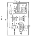
- Cell imaging apparatus 100 includes first specimen cell 10a, second specimen cell 10b, stage 20, light source unit 40, image capture unit 50, drive unit 60, controller 70, and display unit 80.
- Cell imaging apparatus 100 is an apparatus that captures images of cells contained in a liquid specimen, for example, cells in a urine specimen taken from a subject.
- Cell imaging apparatus 100 is configured to charge first specimen cell 10a with a urine specimen, charge second specimen cell 10b with a urine specimen, cause image capture unit 50 to capture images of cells in the first specimen cell 10a, and cause image capture unit 50 to capture images of cells in second specimen cell 10b.
- the liquid specimen subjected to the image capture may be any, as long as the liquid specimen is a biological specimen containing cells of multiple types with difference sizes.
- the liquid specimen may be blood, coelomic fluid, uterine cervical tissue, or the like.
- Image capture unit 50 includes image capture element 51, which is a CCD image sensor or a CMOS image sensor, and objective lens 52.
- First specimen cell 10a and second specimen cell 10b are attached to stage 20.
- first specimen cell 10a and second specimen cell 10b are aligned in an X direction, which is one of the horizontal directions.
- the X direction is a direction that intersects with a vertical direction.
- the X direction includes an X1 direction extending from first specimen cell 10a to second specimen cell 10b, and an X2 direction extending from second specimen cell 10b to first specimen cell 10a.
- first specimen cell 10a and second specimen cell 10b may be arranged in a Y direction perpendicular to the X direction.
- Three or more specimen cells may be provided on stage 20.
- the three or more specimen cells are aligned in a row in the X direction on stage 20.
- first specimen cell 10a and second specimen cell 10b have the same configuration.
- first specimen cell 10a and second specimen cell 10b are referred to specimen cells 10.
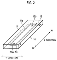
- Each specimen cell 10 includes inner space 11 that holds a urine specimen, inlet port 12 communicating with inner space 11, and outlet port 13 communicating with inner space 11.
- Specimen cell 10 is shaped like a flat cuboid elongated in one direction and is made of a transparent material.
- Inner space 11 is a space having a flat cuboid shape elongated in the one direction, and is provided inside specimen cell 10.
- a longitudinal direction of inner space 11 is the same as a longitudinal direction of specimen cell 10, and specifically the two directions are the X direction.
- Each surface of inner space 11 is flat. In other words, as illustrated in Fig. 1 , inner space 11 of first specimen cell 10a and inner space 11 of second specimen cell 10b are aligned in a row in the X direction, which is the longitudinal direction of inner spaces 11.
- inlet port 12 extends in the Y direction, which is perpendicular to the longitudinal direction.
- outlet port 13 extends in the Y direction as in the case of inlet port 12.
- inlet port 12 and outlet port 13 is opened to a side surface of specimen cell 10.
- Specimen cell 10 includes first reference mark 16a at a position on an outlet port 13 side of inner space 11, and second reference mark 16b at a position on an inlet port 12 side of inner space 11.
- First reference mark 16a and second reference mark 16b are formed by laser processing on bottom surface 11 a of inner space 11.
- First reference mark 16a and second reference mark 16b are aligned in the X direction.
- First reference mark 16a and second reference mark 16b may be provided at positions not on bottom surface 11 a of inner space 11 but on a place such as a top or bottom surface of specimen cell 10 or a top surface of inner space 11. Specimen cell 10 does not necessarily have to be provided with first reference mark 16a or second reference mark 16b.
- cell imaging apparatus 100 includes specimen introduction unit 150, aspiration tube 151, and transport unit 170.
- Specimen introduction unit 150 includes a tube connected to first specimen cell 10a and second specimen cell 10b, electromagnetic valves, and pump 152.
- a portion of the tube extending from aspiration tube 151 is branched at a certain midpoint.
- One of the branches is connected to inlet port 12 of first specimen cell 10a through an electromagnetic valve, and another branch is connected to inlet port 12 of second specimen cell 10b thorough another electromagnetic valve.
- a branch of the tube extending from outlet port 13 of first specimen cell 10a and another branch of the tube extending from outlet port 13 of second specimen cell 10b are met and connected to pump 152.
- An electromagnetic valve is provided between outlet port 13 of first specimen cell 10a and the meeting point, and another electromagnetic valve is provided also between outlet port 13 of second specimen cell 10b and the meeting point.
- Pump 152 is connected through the tube and still another electromagnetic valve to a container 153 in which a buffer is accommodated. The buffer is charged into the tube for introduction of urine specimens.
- Container 153 is connected to cleaning bath 154 through the tube and another electromagnetic valve. The buffer is supplied to cleaning bath 154, and used also as a cleaning solution. Waste liquid container 155 is provided below cleaning bath 154.
- Aspiration tube 151 is connected to drive unit 156 including a motor.
- Drive unit 156 moves aspiration tube 151.
- transport unit 170 includes a belt conveyer, and transports rack 161 capable of holding specimen containers 160, which are urine collection tubes.
- specimen containers 160 are transported one after another to an aspiration position below aspiration tube 151.
- Transport unit 170 transports one of specimen containers 160 containing the urine specimen to be subjected to the image capture to the aspiration position.
- Aspiration tube 151 is inserted into specimen container 160.
- pump 152 When pump 152 is operated, the urine specimen in specimen container 160 is aspirated through aspiration tube 151. After a predetermined amount of the urine specimen is aspirated, aspiration tube 151 is taken out of specimen container 160.
- pump 152 keeps operating also after aspiration tube 151 is taken out of specimen container 160, air is aspirated through aspiration tube 151, and the urine specimen is introduced through inlet port 12 to inner space 11 of first specimen cell 10a. Since the electromagnetic valves provided upstream and downstream of second specimen cell 10b are closed, no urine specimen is introduced into inner space 11 of second specimen cell 10b. Since pump 152 keeps operating until the urine specimen starts to flow out of outlet port 13 of first specimen cell 10a, the urine specimen is charged into the entire inner space 11 of first specimen cell 10a.
- aspiration tube 151 and specimen cell 10a are cleaned.
- aspiration tube 151 is moved to cleaning bath 154.
- pump 152 When pump 152 is operated, the buffer is supplied to inner space 11 of first specimen cell 10a, and inner space 11 is cleaned.
- the urine specimen pushed out of inner space 11 is discharged through aspiration tube 151 to cleaning bath 154.
- pump 152 When pump 152 is further operated, the buffer is discharged from aspiration tube 151, and the inside of aspiration tube 151 is cleaned.
- the buffer is supplied from container 153 to cleaning bath 154, and the outside of aspiration tube 151 is cleaned.
- the waste liquid from cleaning bath 154 is stored in waste liquid container 155.
- second specimen cell 10b When second specimen cell 10b is charged with a urine specimen, and images of cells in the urine specimen are captured, the electromagnetic valves on the branch of the tube connected to first specimen cell 10a are closed, whereas the electromagnetic valves on the branch of the tube connected to second specimen cell 10b are opened.
- the other operations are the same as in the case where first specimen cell 10a is charged with a urine specimen, and images of cells in the urine specimen are captured.
- specimen cell 10 is fixed to stage 20 with bottom surface 11 a of inner space 11 on which first reference mark 16a and second reference mark 16b is provided being located on a lower side.
- Bottom surface 11 a of specimen cell 10 extends substantially horizontally
- Specimen cell 10 is fixed to stage 20 in an undetachable manner. Specimen cell 10 may be discarded after a single use. In such a case, stage 20 is configured to allow specimen cell 10 to be attached and detached.
- drive unitn 60 includes first drive unit 61 and second drive unit 62, and shifts the position of objective lens 52 with respect to first specimen cell 10a and second specimen cell 10b.
- First drive unit 61 includes an electric motor.
- First drive unit 61 moves image capture unit 50 in a Z direction, which is the vertical direction.
- the Z direction includes a Z1 direction, which is an upward vertical direction, and a Z2 direction, which is a downward vertical direction.
- the Z direction is an optical axis direction of objective lens 52. A focus of objective lens 52 is adjusted by moving image capture unit 50 in the Z direction.
- Light source unit 40 is provided below stage 20.
- Light source unit 40 includes LED light source 41, scattering plate 42, and lens 43.
- Light source 41 is a pulsed light source that emits pulsed light at regular intervals, and each emission period is 140 to 200 ⁇ sec. For irradiation of specimen cell 10 with light, light source 41 emits light upward. Scattering plate 42 and lens 43 are arranged above light source 41. Light emitted from light source 41 is scattered by scattering plate 42, and converted to parallel light by lens 43. Specimen cell 10 is irradiated with the parallel light.
- Image capture unit 50 is provided above stage 20.
- Image capture element 51 and objective lens 52 are arranged along the same optical axis as that of light source unit 40, with image capture element 51 being located on an upper side and objective lens 52 being located on a lower side.
- Image capture element 51 and objective lens 52 are held in a single optical column. In other words, the distance between image capture element 51 and objective lens 52 does not change.
- a configuration may be employed in which image capture element 51 is fixed to an optical base, and only objective lens 52 is movable.
- the magnification of objective lens 52 is 15 times. However, the magnification is not limited to 15 times, as long as images of cells such as white blood cells, red blood cells, and epithelial cells, and other formed elements such as urinary cast in urine can be magnified to suitable sizes.
- stage 20 is attached to linear motion guide 21.
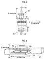
- Linear motion guide 21 guides the movement of stage 20 in an X' direction, which is an inclined direction inclined from the X direction in the Z direction by a predetermined angle.
- An inclined angle of the X' direction from the X direction is very small, and the X' direction is substantially the same as the X direction.
- the X' direction includes an X1' direction, which is the X1 direction inclined in the Z direction, and an X2' direction, which is an X2 direction inclined in the Z direction.
- Linear motion guide 21 is a restriction unit that restricts the moving direction of stage 20 to the X' direction.
- First specimen cell 10a and second specimen cell 10b are fixed to stage 20. When stage 20 moves, first specimen cell 10a and second specimen cell 10b also move together with stage 20. In addition, even when stage 20 moves, the relative positional relationship between first specimen cell 10a and second specimen cell 10b does not change.
- second drive unit 62 includes an electric motor. Second drive unit 62 moves stage 20 in the X1' direction and the X2' direction. When stage 20 moves in the X1' direction or the X2' direction, the visual field of objective lens 52 moves in the X2 direction or the X1 direction. When the subject of the image capture is switched between first specimen cell 10a and second specimen cell 10b, second drive unit 62 moves stage 20 in the X1' direction or the X2' direction. Also in this case, the visual field of objective lens 52 moves in the X2 direction or the X1 direction.
- drive unit 60 moves only one of image capture unit 50 and stage 20.
- specimen cell 10 Even when specimen cell 10 is disposed on stage 20 so as not to be inclined from a horizontal direction, specimen cell 10 may be slightly inclined from the horizontal direction because of machine difference. Moreover, specimen cell 10 may be inclined upward from the horizontal direction or downward from the horizontal direction. In this respect, specimen cell 10 is moved in the direction inclined from the horizontal direction by a predetermined angle, which is larger than an inclination angle possibly caused by the machine difference in this embodiment. This enables the direction in which objective lens 52 is moved in an image capture step described later to be common among urine specimens, making it possible to simplify the motion mechanism and the motion control of objective lens 52.
- Controller 70 includes CPU 71, memory 72, and communication interface 73. Controller 70 controls each of light source unit 40, image capture unit 50, first drive unit 61, second drive unit 62, and display unit 80. Controller 70 receives images captured by image capture unit 50. Controller 70 conducts predetermined processes on the captured images. Controller 70 includes in-focus detection unit 74 that executes an autofocus operation of image capture unit 50.
- controller 70 communicates with the personal computer, and transmits the images of the cells to the personal computer.
- the personal computer performs image processing such as cutting-out of a partial image of each cell.
- Display unit 80 includes a liquid-crystal display panel. Display unit 80 is connected to controller 70, and controlled by controller 70 to display a screen. Display unit 80 displays captured images, partial images obtained by the image processing, and the like. When a personal computer executes the image processing, the captured images or the partial images obtained by the image processing may be displayed on a display unit of the personal computer.
- image capture unit 50 captures images of cells contained in urine specimens charged in inner spaces 11 of first specimen cell 10a and second specimen cell 10b.
- the visual field of objective lens 52 is moved in the X1 direction by moving stage 20 in the X2' direction at a constant speed and simultaneously moving objective lens 52 in the Z2 direction at a constant speed, which is a moving speed according to the inclination of the X2' direction from the X2 direction.
- the images are captured at multiple image capture positions. In this manner, the focus can be adjusted to the vicinity of the bottom surface of inner space 11, without detecting an in-focus state at each image capture position.
- stage 20 is moved in the X1' direction or the X2' direction. The operations of cell imaging apparatus 100 are described below.
- cell imaging apparatus 100 executes an initialization operation.
- the initialization operation includes a moving speed determination operation of determining the moving speed of image capture unit 50 in capturing images of cells in urine. With reference to Fig. 6 , the moving speed determination operation is described.
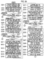
- Step S101 CPU 71 controls pump 152 to charge the buffer into flow paths extending from container 153 thorough first specimen cell 10a or second specimen cell 10b to aspiration tube 151. Consequently, the buffer is held in inner spaces 11 of first specimen cell 10a and second specimen cell 10b.
- Step S102 CPU 71 controls second drive unit 62 to move stage 20 in the X2' direction and position image capture unit 50 at first reference mark 16a on the outlet port 13 side of first specimen cell 10a.
- Step S103 CPU 71 detects a first in-focus position, which is an in-focus position of objective lens 52 at first reference mark 16a of first specimen cell 10a.
- controller 70 executes an autofocus operation three times. In each autofocus operation, first drive unit 61 moves objective lens 52 in the Z1 direction or the Z2 direction, and in-focus detection unit 74 detects a state where first reference mark 16a comes into focus.
- the autofocus operation is based on a contrast detection method.
- the position of objective lens 52 at which the contrast of an image acquired by image capture element 51 can be maximized is detected as an in-focus position of objective lens 52.
- the detected in-focus position is stored in memory 72 of controller 70.
- An autofocus operation based on a method other than the contrast detection method may be employed.
- known autofocus operations such as those based on the phase-difference detection method, the line sensor method, the ultrasonic method, the infrared method, and the like.
- CPU 71 excludes one of the obtained three in-focus positions which has the most distant numeric value indicating the in-focus position, and determines an average value of the remaining two in-focus positions.
- CPU 71 stores the obtained average value as the first in-focus position in memory 72.
- Step S104 CPU 71 controls second drive unit 62 to move stage 20 in the X2' direction, and positions image capture unit 50 at second reference mark 16b on the inlet port 12 side of first specimen cell 10a. Since first reference mark 16a and second reference mark 16b are aligned in the X2 direction, a state where objective lens 52 faces first reference mark 16a can be shifted to a state where objective lens 52 faces second reference mark 16b only by moving stage 20 in the X2' direction.
- Step S105 CPU 71 detects a second in-focus position, which is an in-focus position of objective lens 52 at second reference mark 16b of first specimen cell 10a. To detect the second in-focus position, controller 70 executes an autofocus operation three times.
- CPU 71 excludes one of the three obtained in-focus positions which has the most distant numeric value indicating the in-focus position, and determines an average value of the remaining two in-focus positions.
- CPU 71 stores the obtained average value as the second in-focus position in memory 72.
- the first and second in-focus positions may be detected by using two positions in first specimen cell 10a where no reference marks are provided.
- the first and second in-focus positions may be detected not in the state where inner space 11 is charged with the buffer but in a state where inner space 11 is charged with a urine specimen, or in a state where inner space 11 is filled with air. It is also possible to detect the first and second in-focus positions by charging inner space 11 with a control specimen containing standard particles having a predetermined size, and adjusting the focus on the standard particles. The same shall apply to second specimen cell 10b.
- the number of times of the autofocus operation for detecting each of the first and second in-focus positions is not limited to three.
- the autofocus operation may be conducted only once or multiple times other than three times. Note, however, that since the increase in the number of times of the autofocus operation leads to a longer operation time, the number of times is preferably a smallest possible number. From the viewpoint of detection precision, the autofocus operation is preferably executed multiple times.
- the average value of the two in-focus positions is calculated for the detection of the first in-focus position.
- the first in-focus position is not limited thereto.
- the first in-focus position may be an average value of three in-focus positions, or may be the central one of the three in-focus positions. The same shall apply to the second in-focus position.
- Step S106 CPU 71 determines a first moving speed, which is a moving speed of objective lens 52 for first specimen cell 10a, by using the first in-focus position and the second in-focus position.
- images are captured at multiple image capture positions.
- image capture unit 50 executes image capture multiple times, while second drive unit 62 is moving stage 20 in the X2' direction at a constant speed, as described later. Since cells in the urine specimen introduced in inner space 11 are located above bottom surface 11 a, cell imaging apparatus 100 adjusts the focus of objective lens 52 to a position away from bottom surface 11a by a constant distance in the upward direction for each image capture position.
- the moving direction of stage 20 is inclined from the horizontal direction.
- the position of objective lens 52 at which the position away from bottom surface 11 a of inner space 11 by the constant distance in the upward direction comes into focus is different at different image capture positions.
- the distance between objective lens 52 and the bottom surface 11a of specimen cell 10 changes.
- objective lens 52 has to move in the Z direction by the same distance as a distance by which the position of specimen cell 10a is shifted in the Z direction as a results of the movement of specimen cell 10 in the X2' direction.
- first drive unit 61 moves image capture unit 50 in the Z2 direction at a constant speed.
- the movement of stage 20 in the X2' direction and the movement of image capture unit 50 in the Z2 direction are combined, and the resultant relative movement between specimen cell 10 and objective lens 52 is a constant-speed movement in the X direction, i.e., in the horizontal direction. Consequently, the visual field of objective lens 52 moves in the X1 direction.
- the first moving speed is determined at which objective lens 52 is to be moved in the Z2 direction during a period for which stage 20 moves in the X2' direction at the constant speed.
- stage 20 By moving stage 20 in the X2' direction, cells in each specimen cell are moved in the Z2 direction.
- the direction in which objective lens 52 is moved can be always the Z2 direction in capturing images of cells in every specimen cell. For this reason, even when the specimen cell is inclined because of machine difference, the position of objective lens 52 with respect to the specimen cell can be moved in the X direction, while the structure of drive unit 60 and the motion control of objective lens 52 are simplified.
- the inclination of the X' direction from the X direction is very small, and the X' direction is substantially the same as the horizontal direction. Accordingly, the distance by which image capture unit 50 moves in the Z2 direction is much smaller than the distance by which stage 20 moves in the X2' direction.
- the above-described very small inclination of the X' direction from the X direction eliminates the need for a large space for moving image capture unit 50 in the Z direction, and makes it possible to prevent the increase in size of the apparatus.
- stage 20 moves not in the X' direction but in the X direction, which is the horizontal direction.
- image capture unit 50 does not necessarily have to be moved in the Z direction in the image capture step.
- first specimen cell 10a and second specimen cell 10b are fixed to stage 20, while being inclined from the horizontal direction so that the longitudinal directions of inner spaces 11 can be equal to the X' direction, and stage 20 is moved in the X direction.
- bottom surface 11 a of each inner space 11 is inclined from the horizontal direction.
- objective lens 52 is moved in the Z direction according to the amount of the movement of stage 20 to keep constant the distance between objective lens 52 and bottom surface 11a.
- a period from the start to the end of the visual field movement i.e., the period for which first drive unit 61 moves objective lens 52 (hereinafter, referred to as "set period") is set in advance.
- the set period is also a period for which second drive unit 62 moves stage 20.
- the moving speed of objective lens 52 is a speed at which objective lens 52 moves from the first in-focus position to the second in-focus position in the set period. Specifically, the moving speed of objective lens 52 is determined by calculating the distance between the first in-focus position and the second in-focus position in the Z direction, and dividing the calculated distance by the set period.
- specimen cell 10 When specimen cell 10 is provided with three or more reference marks which are away from each other in the X direction, it is possible to detect an in-focus position for each of these reference marks and determine the moving speed based on the detected three or more positions.
- CPU 71 After determining the first moving speed, CPU 71 stores first speed information indicating the first moving speed in memory 72.
- the first speed information is information used to adjust the focus of each visual field of the objective lens 52 in first specimen cell 10a.
- CPU 71 determines the first moving speed of objective lens 52 to be employed when images of cells in a urine specimen held in first specimen cell 10a are captured, as described above.
- CPU 71 determines a second moving speed, which is a moving speed of objective lens 52 for capturing images of cells in a urine specimen held in second specimen cell 10b.
- Step S107 CPU 71 controls second drive unit 62 to move stage 20 in the X2' direction and position image capture unit 50 at first reference mark 16a on the outlet port 13 side of second specimen cell 10b. Since first specimen cell 10a and second specimen cell 10b are aligned in the X2 direction, the state where objective lens 52 faces second reference mark 16b of first specimen cell 10a can be shifted to a state where objective lens 52 faces first reference mark 16a of second specimen cell 10b only by moving stage 20 in the X2' direction.
- Step S108 CPU 71 detects a third in-focus position, which is an in-focus position of objective lens 52 at first reference mark 16a of second specimen cell 10b.
- the process in Step S108 is the same as that in Step S103.
- Step S109 CPU 71 controls second drive unit 62 to move stage 20 in the X2' direction and position image capture unit 50 at second reference mark 16b on the inlet port 12 side of second specimen cell 10b.
- Step S110 CPU 71 detects a fourth in-focus position, which is an in-focus position of objective lens 52 at second reference mark 16b of second specimen cell 10b.
- the process in Step S 110 is the same as that in Step S105.
- Step S111 CPU 71 determines the second moving speed by using the third in-focus position and the fourth in-focus position.
- the process in Step S111 is the same as that in Step S106.
- CPU 71 After determining the second moving speed, CPU 71 stores second speed information indicating the second moving speed in memory 72.
- the second speed information is information used to adjust the focus of each visual field of objective lens 52 in second specimen cell 10b.
- Step S111 CPU 71 terminates the moving speed determination operation.
- cell imaging apparatus 100 When the initialization operation is completed, cell imaging apparatus 100 is placed in a standby state. In the standby state, cell imaging apparatus 100a can accept a urine specimen.
- CPU 71 can set a normal mode, which is a first mode, or a thorough examination mode, which is a second mode, selectively.
- cell imaging apparatus 100 in the standby state receives from a user an instruction to start the image capture of a urine specimen, cell imaging apparatus 100 executes a urine specimen image capture process.
- the urine specimen image capture process is described with reference to Figs. 8A to 8C .
- flow paths extending from aspiration tube 151 to pump 152 including inner spaces 11 of first specimen cell 10a and second specimen cell 10b are charged with the buffer.
- Step S201 CPU 71 controls second drive unit 62 to move stage 20 in the X1' direction and position image capture unit 50 at first reference mark 16a on the outlet port 13 side of first specimen cell 10a.
- a moving speed of stage 20 in Step S201 is a second speed higher than the first speed, at which stage 20 moves for moving the visual field to capture images of cells.
- Step S202 CPU 71 detects the first in-focus position, which is the in-focus position of objective lens 52 at first reference mark 16a of first specimen cell 10a, and stores the first in-focus position in memory 72.
- Step S202 is referred to as "autofocus step.”
- the first in-focus position is detected in the moving speed determination operation
- the first in-focus position is detected again in the autofocus step.
- This is intended to correct the shift of the in-focus position with the lapse of time.
- the temperature of a room in which cell imaging apparatus 100 is placed may change with the lapse of time, and the change in temperature may cause changes in distances between units in cell imaging apparatus 100, for example, a change in distance between objective lens 52 and first specimen cell 10a. Accordingly, if objective lens 52 is positioned at the first in-focus position detected in the moving speed determination operation, the focus of objective lens 52 may be shifted from bottom surface 11a because of the change in temperature. For this reason, the first in-focus position is detected again in the autofocus step, and objective lens 52 is focused on bottom surface 11 a of inner space 11.
- Step S203 CPU 71 controls transport unit 170 to position specimen container 160 containing a urine specimen to be subjected to the image capture to the aspiration position.
- Step S204 CPU 71 determines whether the urine specimen to be subjected to the image capture should be subjected to the image capture in the normal mode or in the thorough examination mode. Whether the urine specimen should be subjected to the image capture in the normal mode or in the thorough examination mode can be determined by various methods. For example, a barcode containing information indicating whether the urine specimen should be subjected to the image capture in the normal mode or in the thorough examination mode is attached to the specimen container, and the information is read out of the barcode with a barcode reader. In this manner, whether the urine specimen should be subjected to the image capture in the normal mode or in the thorough examination mode can be determined.
- a barcode of sample ID is attached to the specimen container, and the sample ID is read out with a barcode reader. Then, the sample ID is transmitted to a host computer to inquire whether the urine specimen should be subjected to the image capture in the normal mode or in the thorough examination mode. In addition, a user can designate whether the urine specimen should be subjected to the image capture in the normal mode or in the thorough examination mode by operating an input unit provided in cell imaging apparatus 100.
- CPU 71 proceeds to "normal mode” in Step S204, and executes Step S205.
- CPU 71 proceeds to "thorough examination mode” in Step S204, and executes Step S233.
- Step S205 CPU 71 controls drive unit 156 and specimen introduction unit 150 to insert aspiration tube 151 into specimen container 160, aspirate a predetermined amount of the urine specimen from specimen container 160, and introduce the urine specimen into inner space 11 of first specimen cell 10a.
- the urine specimen is neither mixed with any reagent such as a staining solution or a diluent, nor subjected to centrifugation.
- Step S205 is referred to as "specimen introduction step.”
- the urine specimen is aspirated once per specimen container 160 in the specimen introduction step.
- first specimen cell 10a and second specimen cell 10b are charged with different urine specimens taken from different subjects.
- Step S206 CPU 71 waits for a predetermined period, for example, for 100 seconds. As a result, cells in the urine specimen held in first specimen cell 10a are settled, and many cells are disposed on bottom surface 11 a of inner space 11.
- Step S206 is referred to as "settlement step.”
- Step S207 during the settlement step on first specimen cell 10a, CPU 71 controls second drive unit 62 to move stage 20 in the X2' direction and position image capture unit 50 at first reference mark 16a of second specimen cell 10b.
- the moving speed of stage 20 in Step S207 is the second speed as in the case of Step S201.
- Step S208 the autofocus step is executed on second specimen cell 10b.
- CPU 71 detects the third in-focus position, which is the in-focus position of objective lens 52 at first reference mark 16a of second specimen cell 10b.
- the process in Step S208 is the same as that in Step S202.
- Step S209 CPU 71 controls transport unit 170 to transport rack 161, and position specimen container 160 containing a next urine specimen to be subjected to the image capture at the aspiration position.
- Step S210 CPU 71 determines whether the urine specimen to be subjected to the image capture should be subjected to the image capture in the normal mode or in the thorough examination mode.
- the process in Step S210 is the same as that in Step S204.
- CPU 71 proceeds to "normal mode” in Step S210, and executes Step S211.
- CPU 71 proceeds to "thorough examination mode” in Step S210, and executes Step S257.
- Step S211 CPU 71 executes the specimen introduction step on second specimen cell 10b.
- CPU 71 controls drive unit 156 and specimen introduction unit 150 to insert aspiration tube 151 into specimen container 160, aspirate a predetermined amount of the urine specimen from specimen container 160, and introduce the urine specimen into inner space 11 of second specimen cell 10b.
- Step S212 CPU 71 starts the settlement step on second specimen cell 10b. In other words, CPU 71 waits for a predetermined period, for example, for 100 seconds.
- Step S213 during the settlement step on second specimen cell 10b, CPU 71 controls second drive unit 62 to move stage 20 in the X1' direction, and position image capture unit 50 at first reference mark 16a of first specimen cell 10a.
- the moving speed of stage 20 in Step S213 is the second speed as in the case of Step S201.
- Step S214 CPU 71 controls first drive unit 61 to position objective lens 52 at an image capture start position, which is a corrected position away from the first in-focus position by a predetermined offset amount in the upward direction.
- the offset amount is described.
- objective lens 52 is focused on bottom surface 11a. Since most cells are arranged on bottom surface 11a, the focus of objective lens 52 is not on the cell. When an image is captured in this state, the image of the cell is unclear. Accordingly, to adjust the focus of objective lens 52 to the cell, objective lens 52 is moved upward by an amount which is about equal to the radius of the cell, and the focus of objective lens 52 is positioned near a center of the cell.
- the offset amount is stored in memory 72 in advance.
- the offset amount is set to, for example, 5 to 6 ⁇ m, objective lens 52 is focused on red blood cells. Note, however, that the offset amount does not necessarily have to be 5 to 6 ⁇ m, but the offset amount can be set, as appropriate, according to the sizes of cells of interest.
- the offset amount may be a distance from the surface on which first reference mark 16a and second reference mark 16b are provided to the position of the center of the cell of interest in the Z direction.
- Step S215 of Fig. 8 CPU 71 reads out the first speed information for first specimen cell 10a from memory 72.
- Step S216 the image capture step in which images of cells are captured in multiple visual fields.
- CPU 71 controls first drive unit 61 and second drive unit 62 to simultaneously start the movement of stage 20 in the X2' direction and the movement of image capture unit 50 in the Z2 direction.
- First drive unit 61 moves image capture unit 50 in the Z2 direction for the set period at the first moving speed indicated in the first speed information without any stop during the movement.
- second drive unit 62 moves stage 20 in the X2' direction for the set period at the set first speed without any stop during the movement.
- CPU 71 controls image capture unit 50 to execute image capture multiple times.
- the visual field of objective lens 52 moves in the X1 direction from first reference mark 16a to second reference mark 16b.
- Image capture unit 50 captures images at multiple image capture positions in a region between first reference mark 16a and second reference mark 16b.
- stage 20 When stage 20 continues to move in the X2' direction at a set speed, image capture unit 50 continues to move in the Z2 direction at the first moving speed indicated in the first speed information.
- the X2' direction includes a component in the Z2 direction and a component in the X2 direction.
- the movement of stage 20 in the X2' direction means that stage 20 moves in the Z2 direction and the X2 direction.
- bottom surface 11 a of inner space 11 of first specimen cell 10a moves in the Z2 direction.
- the distance between bottom surface 11a and objective lens 52 is kept constant. Accordingly, objective lens 52 moves relative to first specimen cell 10a in parallel with bottom surface 11 a of inner space 11. In other words, the position of objective lens 52 with respect to first specimen cell 10a and second specimen cell 10b moves in the X direction.
- the focus is adjusted by moving objective lens 52 at the determined and constant moving speed, without detecting the in-focus state at every image capture position. Accordingly, the time of the image capture step can be shortened.
- the focus position does not affected by the concentration of the cells or the sizes of the cells in the urine specimen, and the same focus position can be employed at all the image capture positions. Since images are captured with stage 20 kept moving in the X2' direction, it is unnecessary to stop stage 20 at each image capture position for the image capture. Hence, it is possible to prevent vibration of cells in the urine specimen due to the stop of stage 20. Accordingly, it is unnecessary to wait until the vibration of the cells stops, and clear images of cells can be obtained stably.
- objective lens 52 is located at a position facing second reference mark 16b of first specimen cell 10a.
- second reference mark 16b is positioned on the optical axis of image capture unit 50.
- Step S217 of Fig. 8A CPU 71 controls specimen introduction unit 150 and drive unit 156 to move aspiration tube 151 to cleaning bath 154 and clean first specimen cell 10a and aspiration tube 151, which have been used for the image capture of the cells, with the buffer.
- Step S217 is referred to as "cleaning step.”
- Step S218, CPU 71 executes image processing to cut out partial images of cells and other formed elements from the images obtained by image capture unit 50.
- Step S219 CPU 71 displays the cut-out partial images on display unit 80.
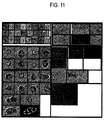
- Fig. 11 illustrates an example of image display in the cell imaging apparatus. As illustrated in Fig. 11 , display unit 80 displays multiple arranged images of cells and other formed elements contained in a single urine specimen.
- Step S220 of Fig. 8A CPU 71 controls second drive unit 62 to move stage 20 in the X1' direction and position image capture unit 50 at first reference mark 16a of first specimen cell 10a.
- Step S221 CPU 71 executes the autofocus step on first specimen cell 10a.
- CPU 71 detects the first in-focus position, which is the in-focus position of objective lens 52 at first reference mark 16a of first specimen cell 10a.
- the process in Step S221 is the same as that in Step S202.
- Step S222 CPU 71 controls transport unit 170 to transport rack 161 and position specimen container 160 containing a next urine specimen to be subjected to the image capture to the aspiration position.
- Step S223 CPU 71 determines whether the urine specimen to be subjected to the image capture should be subjected to the image capture in the normal mode or in the thorough examination mode.
- the process in Step S223 is the same as that in Step S204.
- CPU 71 proceeds to "normal mode” in Step S223, and executes Step S224.
- CPU 71 proceeds to "thorough examination mode” in Step S223, and executes Step S233.
- Step S224 CPU 71 executes the specimen introduction step on first specimen cell 10a.
- the process in Step S224 is the same as that in Step S205.
- Step S225 CPU 71 starts the settlement step on first specimen cell 10a. In other words, CPU 71 waits for a predetermined period, for example, for 100 seconds.
- Step S2266 during the settlement step on first specimen cell 10a, CPU 71 controls second drive unit 62 to move stage 20 in the X2' direction and position image capture unit 50 at first reference mark 16a of second specimen cell 10b.
- the moving speed of stage 20 in Step S226 is the second speed as in the case of Step S201.
- Step S227 CPU 71 controls first drive unit 61 to position objective lens 52 at an image capture start position, which is a corrected position away from the third in-focus position by the predetermined offset amount in the upward direction.
- Step S228, CPU 71 reads out the second speed information for second specimen cell 10b from memory 72.
- CPU 71 executes in Step S229 the image capture step of capturing images of cells in the urine specimen held in second specimen cell 10b at multiple image capture positions.
- CPU 71 controls second drive unit 62 to move stage 20 at the first speed in the X2' direction, and controls first drive unit 61 to move image capture unit 50 at the second moving speed in the Z2 direction.
- first specimen cell 10a and second specimen cell 10b are moved in the X direction with respect to objective lens 52, and the visual field of objective lens 52 moves in the X1 direction in inner space 11 of second specimen cell 10b.
- stage 20 moves in the X2' direction, which is one side of the X' direction
- objective lens 52 moves in the Z2 direction, which is one side of the Z direction.
- stage 20 moves to the lower left in Fig. 7
- objective lens 52 moves downward in Fig. 7 .
- the moving direction of stage 20 and the moving direction of objective lens 52 are the same between the image capture steps on first specimen cell 10a and second specimen cell 10b. This facilitates the control of drive unit 60.
- CPU 71 executes in Step S230 the cleaning step on second specimen cell 10b.
- CPU 71 controls specimen introduction unit 150 and drive unit 156 to move aspiration tube 151 to cleaning bath 154 and clean second specimen cell 10b and aspiration tube 151, which have been used for the image capture of the cells, with the buffer.
- Step S231 CPU 71 executes image processing to cut out partial images of cells and other formed elements from the images obtained by image capture unit 50.
- Step S232 CPU 71 displays the cut-out partial images on display unit 80.
- CPU 71 proceeds to Step S207. After that, CPU 71 executes steps on second specimen cell 10b.
- the autofocus operation is executed only for the detection of the first in-focus position at first reference mark 16a.
- the autofocus operation is executed only for the detection of the third in-focus position at first reference mark 16a.
- the following configuration may be employed. Specifically, pieces of information indicating the first and second in-focus positions detected in the moving speed determination operation are stored. For capturing images in first specimen cell 10a, the stored information indicating the first in-focus position is used to position objective lens 52 at the first in-focus position. Meanwhile, for capturing images in second specimen cell 10b, the stored information indicating the third in-focus position is used to position objective lens 52 at the third in-focus position.
- the second in-focus position and the fourth in-focus position may be detected in addition to the first in-focus position and the third in-focus position.
- CPU 71 determines the moving speed of image capture unit 50 for each urine specimen. Accordingly, it is unnecessary to execute the moving speed determination operation during the initialization operation. This makes it possible to precisely adjust the focus of objective lens 52 in each image capture step.
- first reference mark 16a and second reference mark 16b relative distances from multiple positions on bottom surface 11a of inner space 11 are detected by using an optical or ultrasonic distance sensor. Then, the coordinates of the multiple positions are determined on the basis of the detected relative positions. After that, the inclination of the X' direction from the horizontal direction is detected on the basis of the determined coordinates.
- the thorough examination mode is an operation mode in which a larger number of images of cells contained in a urine specimen to be subjected to thorough examination are captured and a larger number of cell images are obtained than in the normal mode to examine the urine specimen in details.
- a specimen subjected to the thorough examination may be a urine specimen which is highly likely to contain urinary casts.
- Another specimen subjected to the thorough examination may be a urine specimen determined to be protein-positive by an analysis conducted with a urine qualitative analyzer in advance.
- Another specimen subjected to the thorough examination may be a urine specimen in which any of urinary casts and epithelial cells other than squamous epithelial cells is detected in an analysis of the urine specimen conducted with a urine formed element analyzer in advance.
- first specimen cell 10a and second specimen cell 10b In the thorough examination mode, aliquots of a single urine specimen taken from a single subject are introduced into first specimen cell 10a and second specimen cell 10b, and images of cells are captured in each of first specimen cell 10a and second specimen cell 10b. For this reason, a larger number of images of cells are obtained in the thorough examination mode than in the normal mode.
- Step S233 and later aliquots of a urine specimen to be subjected to the thorough examination are introduced into first specimen cell 10a and second specimen cell 10b. After that, the image capture step is executed on first specimen cell 10a, and then the image capture step is executed on second specimen cell 10b.
- Step S233 CPU 71 executes the specimen introduction step on first specimen cell 10a.
- the process in Step S233 is the same as that in Step S205.
- the urine specimen to be subjected to the thorough examination is introduced into inner space 11 of first specimen cell 10a.
- Step S234 CPU 71 starts the settlement step on first specimen cell 10a. In other words, CPU 71 waits for a predetermined period, for example, for 100 seconds.
- Step S235 during the settlement step on first specimen cell 10a, CPU 71 controls second drive unit 62 to move stage 20 in the X2' direction and position image capture unit 50 at first reference mark 16a of second specimen cell 10b.
- the moving speed of stage 20 in Step S234 is the second speed as in the case of Step S201.
- Step S236 CPU 71 determines whether or not a urine specimen has been already introduced in inner space 11 of second specimen cell 10b.
- the fact that a specimen has been already introduced in second specimen cell 10b means that second specimen cell 10b is being subjected to the settlement step.
- CPU 71 proceeds to YES in Step S236, and executes Step S237.
- Step S237 to S242 the image capture step, the cleaning step, and the cell image display are executed on second specimen cell 10b.
- the processes in Steps S237 to S242 are the same as those in Steps S227 to S232.
- Step S242 CPU 71 executes Step S243.
- Step S243 CPU 71 controls second drive unit 62 to move stage 20 in the X1' direction and position image capture unit 50 at first reference mark 16a of second specimen cell 10b.
- Step S244 the autofocus step is executed on second specimen cell 10b.
- CPU 71 detects the third in-focus position, which is the in-focus position of objective lens 52 at first reference mark 16a of second specimen cell 10b.
- the process in Step S244 is the same as that in Step S202.
- Step S245 CPU 71 controls drive unit 156 and specimen introduction unit 150 to insert aspiration tube 151 into specimen container 160, aspirate a predetermined amount of a urine specimen from specimen container 160, and introduce the urine specimen to be subjected to the thorough examination into inner space 11 of second specimen cell 10b.
- the urine specimen introduced into second specimen cell 10b is the same as the urine specimen already introduced in inner space 11 of first specimen cell 10a.
- Step S246 CPU 71 starts the settlement step on second specimen cell 10b. In other words, CPU 71 waits for a predetermined period, for example, for 100 seconds.
- Step S247 during the settlement step on second specimen cell 10b, CPU 71 controls second drive unit 62 to move stage 20 in the X1' direction and position image capture unit 50 at first reference mark 16a of first specimen cell 10a.
- the moving speed of stage 20 in Step S247 is the second speed as in the case of Step S201.
- Step S248 CPU 71 controls first drive unit 61 to position objective lens 52 at an image capture start position, which is a position corrected from the first in-focus position by a predetermined offset amount in the upward direction.
- Step S249 CPU 71 reads out first speed information for first specimen cell 10a from memory 72.
- Step S250 the image capture step on first specimen cell 10a.
- the process in Step S250 is the same as that in Step S216.
- CPU 71 executes in Step S251 the cleaning step on first specimen cell 10a.
- CPU 71 controls specimen introduction unit 150 and drive unit 156 to move aspiration tube 151 to cleaning bath 154 and clean first specimen cell 10a and aspiration tube 151, which have been used for the image capture of the cells, with the buffer.
- Step S252 CPU 71 executes image processing to cut out partial images of cells and other formed elements from the images obtained by image capture unit 50.
- Step S253 CPU 71 controls second drive unit 62 to move stage 20 in the X1' direction and position image capture unit 50 at first reference mark 16a of first specimen cell 10a.
- Step S254 CPU 71 executes the autofocus step on first specimen cell 10a.
- CPU 71 detects the first in-focus position, which is the in-focus position of objective lens 52 at first reference mark 16a of first specimen cell 10a.
- the process in Step S254 is the same as that in Step S202.
- Step S255 CPU 71 controls transport unit 170 to transport rack 161 and position specimen container 160 containing a next urine specimen to be subjected to the image capture at the aspiration position.
- Step S256 CPU 71 determines whether the urine specimen to be subjected to the image capture should be subjected to the image capture in the normal mode or in the thorough examination mode.
- the process in Step S256 is the same as that in Step S204.
- CPU 71 proceeds to "normal mode" in Step S256, and executes Step S224.
- Step S224 CPU 71 executes the specimen introduction step on first specimen cell 10a to introduce the next urine specimen into inner space 11 of first specimen cell 10a.
- Step S225 CPU 71 starts the settlement step on first specimen cell 10a. In other words, CPU 71 waits for a predetermined period, for example, for 100 seconds.
- Step S2266 during the settlement step on first specimen cell 10a, CPU 71 controls second drive unit 62 to move stage 20 in the X2' direction and position image capture unit 50 at first reference mark 16a of second specimen cell 10b.
- Step S227 CPU 71 controls first drive unit 61 to position objective lens 52 at an image capture start position, which is a corrected position away from the third in-focus position by the predetermined offset amount in the upward direction.
- Step S228, CPU 71 reads out the second speed information for second specimen cell 10b from memory 72.
- Step S229 the image capture step on second specimen cell 10b.
- the urine specimen introduced in inner space 11 of second specimen cell 10b is a urine specimen to be subjected to the thorough examination.
- CPU 71 executes in Step S230 the cleaning step on second specimen cell 10b.
- Step S231 CPU 71 executes image processing to cut out partial images of cells and other formed elements from the images obtained by image capture unit 50.
- Step S232 CPU 71 displays the cut-out partial images on display unit 80.
- the partial images displayed here are those of cells contained in the urine specimen subjected to the thorough examination.
- CPU 71 displays on a single screen multiple images of cells and formed elements obtained in the image capture steps on first specimen cell 10a and second specimen cell 10b.
- the number of images displayed per single urine specimen subjected to the thorough examination is approximately twice the number of images displayed per single urine specimen in the normal mode.
- the image capture step three times on a single urine specimen by introducing the urine specimen subjected to the image capture twice into first specimen cell 10a and once into second specimen cell 10b and capturing images of cells. It is also possible to execute the image capture step on a single urine specimen more times by introducing the urine specimen to be subjected to the image capture multiple times into each of first specimen cell 10a and second specimen cell 10b and capturing images of cells.
- CPU 71 proceeds to Step S207. After that, CPU 71 executes steps on second specimen cell 10b.
- Step S256 when the urine specimen is determined to be subjected to the thorough examination in Step S256, CPU 71 proceeds to "thorough examination mode", and executes Step S233.
- Step S242 are those of cells contained in the urine specimen subjected to the thorough examination, and include both images obtained by the image capture in first specimen cell 10a and images obtained by the image capture in second specimen cell 10b.
- CPU 71 executes the processes in Step S257 and later.
- Step S257 and later a urine specimen to be subjected to the thorough examination is introduced into each of second specimen cell 10b and first specimen cell 10a, and the image capture step is executed on second specimen cell 10b. After that, the image capture step is executed on first specimen cell 10a.
- the order of the processes on first specimen cell 10a and on second specimen cell 10b in Steps S233 to S256 is reversed in Steps S257 to 279. Since the details of the processes are the same, descriptions of the processes are omitted. Note that, after the cell imaging apparatus 100 completes the initialization operation and is placed in the standby state, the urine specimen is introduced first into first specimen cell 10a in this embodiment.
- cell imaging apparatus 100 efficiently captures images of cells by executing the steps on first specimen cell 10a and the steps on second specimen cell 10b in an overlapping manner. This point will be described in detail with reference to Fig. 12 .
- CPU 71 When the urine specimen image capture process is started, CPU 71 simultaneously executes the specimen introduction step and the autofocus step on first specimen cell 10a.
- image capture unit 50 is disposed to face first specimen cell 10a for the autofocus step.
- the specimen introduction step and the autofocus step may be executed in different periods.
- CPU 71 After completion of the specimen introduction step and the autofocus step, CPU 71 starts the settlement step on first specimen cell 10a. While executing the settlement step on first specimen cell 10a, CPU 71 executes the specimen introduction step and the autofocus step on second specimen cell 10b.
- the urine specimen introduced into first specimen cell 10a and the urine specimen introduced into second specimen cell 10b are different urine specimens taken from different subjects.
- the urine specimen introduced into first specimen cell 10a and the urine specimen introduced into second specimen cell 10b are the same urine specimen taken from a single subject.
- image capture unit 50 has to be disposed to face second specimen cell 10b. Accordingly, CPU 71 causes second drive unit 62 to move stage 20 in the X2' direction, position image capture unit 50 at a position facing second specimen cell 10b, and then execute the autofocus step during the settlement step on first specimen cell 10a.
- CPU 71 starts the settlement step on second specimen cell 10b.
- a final stage of the settlement step on first specimen cell 10a overlaps with an initial stage of the settlement step on second specimen cell 10b.
- CPU 71 After completion of the settlement step on first specimen cell 10a, CPU 71 executes the image capture step on first specimen cell 10a. Before the image capture step is started on first specimen cell 10a, image capture unit 50 faces second specimen cell 10b. Hence, to execute the image capture step on first specimen cell 10a, the image capture unit 50 has to be disposed to face first specimen cell 10a. Accordingly, CPU 71 causes second drive unit 62 to move stage 20 in the X1' direction, position image capture unit 50 to a position facing first specimen cell 10a, and then execute the image capture step during the settlement step on second specimen cell 10b.
- CPU 71 executes the cleaning step on first specimen cell 10a.
- image capture sequence a series of steps (hereinafter, referred to as "image capture sequence") on first specimen cell 10a is completed.
- CPU 71 After completion of the image capture sequence on first specimen cell 10a, CPU 71 starts another image capture sequence on first specimen cell 10a.
- the settlement step on second specimen cell 10b is being executed.
- CPU 71 executes the specimen introduction step and the autofocus step on first specimen cell 10a.
- a urine specimen taken from a subject different from the subject from which the urine specimen introduced in second specimen cell 10b is taken is introduced into first specimen cell 10b.
- the thorough examination mode the same urine specimen taken from the same subject from which the urine specimen introduced in second specimen cell 10b is taken is introduced into first specimen cell 10b.
- image capture unit 50 faces first specimen cell 10a. Accordingly, CPU 71 executes the specimen introduction step and the autofocus step on first specimen cell 10a, without switching the position of image capture unit 50 between first specimen cell 10a and second specimen cell 10b.
- CPU 71 After completion of the specimen introduction step and the autofocus step, CPU 71 starts the settlement step on first specimen cell 10a. A final stage of the settlement step on second specimen cell 10b overlaps with an initial stage of the settlement step on first specimen cell 10a.
- CPU 71 After completion of the settlement step on second specimen cell 10b, CPU 71 executes the image capture step on second specimen cell 10b. Before the image capture step on second specimen cell 10b is started, image capture unit 50 faces first specimen cell 10a. Hence, to execute the image capture step on second specimen cell 10b, image capture unit 50 has to be disposed to face second specimen cell 10b. Accordingly, CPU 71 causes second drive unit 62 to move stage 20 in the X2' direction, position image capture unit 50 to a position facing second specimen cell 10b, and then execute the image capture step during the settlement step on first specimen cell 10a.
- CPU 71 executes the cleaning step on second specimen cell 10b.
- CPU 71 executes the specimen introduction step, the autofocus step, the settlement step, the image capture step, and the cleaning step on each of first specimen cell 10a and second specimen cell 10b in the same manner.
- the image capture step on first specimen cell 10a and the settlement step on second specimen cell 10b are executed simultaneously, and the image capture step on second specimen cell 10b and the settlement step on first specimen cell 10a are executed simultaneously Accordingly, images of cells can be captured efficiently, while single image capture unit 50 is shared by first specimen cell 10a and second specimen cell 10b.
- the specimen introduction step on first specimen cell 10a and the settlement step on second specimen cell 10b are executed simultaneously, and the specimen introduction step on second specimen cell 10b and the settlement step on first specimen cell 10a are executed simultaneously Accordingly, by utilizing the time of the cell settlement step on one specimen cell 10, a urine specimen can be introduced in the other specimen cell 10, while single aspiration tube 151 is shared by first specimen cell 10a and second specimen cell 10b. Thus, images of cells can be captured efficiently.
- the image capture step on one specimen cell 10 and the specimen introduction step or the cleaning step on the other specimen cell 10 may be executed simultaneously. Also with this configuration, the urine specimen image capture processes on first specimen cell 10a and second specimen cell 10b can be carried out simultaneously Hence, images of cells can be captured efficiently, while single image capture unit 50 is shared by first specimen cell 10a and second specimen cell 10b.
- first specimen cell 10a and second specimen cell 10b extend in the X direction.
- the visual field of objective lens 52 is moved in the X direction.
- images of cells can be captured in each of first specimen cell 10a and second specimen cell 10b.
- First specimen cell 10a and second specimen cell 10b are aligned in the X direction in a row.
- objective lens 52 can be moved between first specimen cell 10a and second specimen cell 10b. This makes it possible to rapidly capture images of cells held in first specimen cell 10a and second specimen cell 10b and rapidly switch specimen cell 10 subjected to the image capture, making it possible to improve the efficiency of image capture of multiple specimens.
Landscapes
- Physics & Mathematics (AREA)
- Chemical & Material Sciences (AREA)
- General Physics & Mathematics (AREA)
- Engineering & Computer Science (AREA)
- Analytical Chemistry (AREA)
- Multimedia (AREA)
- Optics & Photonics (AREA)
- Signal Processing (AREA)
- Immunology (AREA)
- Biochemistry (AREA)
- General Health & Medical Sciences (AREA)
- Life Sciences & Earth Sciences (AREA)
- Health & Medical Sciences (AREA)
- Pathology (AREA)
- Computer Vision & Pattern Recognition (AREA)
- Dispersion Chemistry (AREA)
- Investigating Or Analysing Biological Materials (AREA)
- Investigating Or Analysing Materials By Optical Means (AREA)
- Microscoopes, Condenser (AREA)
Abstract
Description
- The invention relates to a cell imaging apparatus and a cell imaging method which are used to capture images of cells contained in a liquid specimen.
- Japanese Patent Application Publication No.
2010-169484 - Suppose a case where the sample processing system disclosed in Japanese Patent Application Publication No.
2010-169484 - A cell imaging apparatus of this disclosure includes an image capture unit, specimen cells, a drive unit, and a controller. The image capture unit includes an objective lens. Each of the specimen cells includes an inner space which is capable of holding a liquid specimen and which is elongated in one direction. The specimen cells are arranged such that the inner spaces are aligned in a row in a longitudinal direction of the inner spaces. The drive unit moves at least one of: a)one or more specimen cells; and b)the objective lens. The controller controls the drive unit to move the specimen cells, the objective lens, or the both in the longitudinal direction, and controls the image capture unit to capture images of cells contained in a liquid specimen held in each of the inner spaces of the specimen cells at multiple image capture positions.
- In a cell imaging method of this disclosure, a first liquid specimen containing cells is introduced into a first specimen cell, and, during a period in which the cells in the first liquid specimen are allowed to settle in the first specimen cell, a second liquid specimen containing cells is introduced into a second specimen cell. In this cell imaging method, during a period in which the cells in the second liquid specimen are allowed to settle in the second specimen cell, images of the cells contained in the first liquid specimen in the first specimen cell are captured. In this cell imaging method, after completion of the capturing of the image of the cells contained in the first liquid specimen, the first liquid specimen is discharged from the first specimen cell, and a third liquid specimen containing cells is introduced into the first specimen cell. Then, during a period in which the cells in the third liquid specimen are allowed to settle in the first specimen cell, images of the cells contained in the second liquid specimen in the second specimen cell are captured.
- The invention makes it possible to improve the efficiency of image capture of multiple specimens in comparison with a conventional case.
-
-
Fig. 1 is a schematic diagram illustrating a configuration of a cell imaging apparatus according to an embodiment; -
Fig. 2 is a perspective view illustrating a configuration of a specimen cell according to the embodiment; -
Fig. 3 is a schematic diagram illustrating a fluid circuit of an imaging unit; -
Fig. 4 is a front view illustrating a configuration of a light source unit and an image capture unit; -
Fig. 5 is a perspective view illustrating a configuration of a mechanism for moving a stage; -
Fig. 6 is a flowchart illustrating a procedure of a moving speed determination operation; -
Fig. 7 is a diagram for illustrating determination of a moving speed of an objective lens; -
Fig. 8A is a flowchart illustrating a procedure of a urine specimen image capture process in a normal mode; -
Fig. 8B is a flowchart illustrating a procedure of a urine specimen image capture process in a thorough examination mode; -
Fig. 8C is a flowchart illustrating a procedure of urine specimen image capture process in the thorough examination mode; -
Fig. 9 is a diagram for illustrating an offset amount of the objective lens; -
Fig. 10 is a diagram for illustrating a focus adjustment of the image capture unit in an image capture operation; -
Fig. 11 illustrates an example of display of cell images; and -
Fig. 12 is a timing chart illustrating operations of the cell imaging apparatus. - Hereinafter, preferred embodiments are described with reference to the drawings.
- A configuration of a cell imaging apparatus is described with reference to
Fig. 1 . Cell imaging apparatus 100 includesfirst specimen cell 10a,second specimen cell 10b,stage 20,light source unit 40,image capture unit 50,drive unit 60,controller 70, anddisplay unit 80. Cell imaging apparatus 100 is an apparatus that captures images of cells contained in a liquid specimen, for example, cells in a urine specimen taken from a subject. Cell imaging apparatus 100 is configured to chargefirst specimen cell 10a with a urine specimen, chargesecond specimen cell 10b with a urine specimen, causeimage capture unit 50 to capture images of cells in thefirst specimen cell 10a, and causeimage capture unit 50 to capture images of cells insecond specimen cell 10b. The liquid specimen subjected to the image capture may be any, as long as the liquid specimen is a biological specimen containing cells of multiple types with difference sizes. For example, the liquid specimen may be blood, coelomic fluid, uterine cervical tissue, or the like. -
Image capture unit 50 includesimage capture element 51, which is a CCD image sensor or a CMOS image sensor, andobjective lens 52.First specimen cell 10a andsecond specimen cell 10b are attached tostage 20. Onstage 20,first specimen cell 10a andsecond specimen cell 10b are aligned in an X direction, which is one of the horizontal directions. The X direction is a direction that intersects with a vertical direction. The X direction includes an X1 direction extending fromfirst specimen cell 10a tosecond specimen cell 10b, and an X2 direction extending fromsecond specimen cell 10b tofirst specimen cell 10a. Note thatfirst specimen cell 10a andsecond specimen cell 10b may be arranged in a Y direction perpendicular to the X direction. - Three or more specimen cells may be provided on
stage 20. In such a case, the three or more specimen cells are aligned in a row in the X direction onstage 20. - As shown in
Fig. 2 ,first specimen cell 10a andsecond specimen cell 10b have the same configuration. Here,first specimen cell 10a andsecond specimen cell 10b are referred tospecimen cells 10. Eachspecimen cell 10 includesinner space 11 that holds a urine specimen,inlet port 12 communicating withinner space 11, andoutlet port 13 communicating withinner space 11.Specimen cell 10 is shaped like a flat cuboid elongated in one direction and is made of a transparent material.Inner space 11 is a space having a flat cuboid shape elongated in the one direction, and is provided insidespecimen cell 10. A longitudinal direction ofinner space 11 is the same as a longitudinal direction ofspecimen cell 10, and specifically the two directions are the X direction. Each surface ofinner space 11 is flat. In other words, as illustrated inFig. 1 ,inner space 11 offirst specimen cell 10a andinner space 11 ofsecond specimen cell 10b are aligned in a row in the X direction, which is the longitudinal direction ofinner spaces 11. - In
Fig. 2 , from one end ofinner space 11,inlet port 12 extends in the Y direction, which is perpendicular to the longitudinal direction. From another end ofinner space 11,outlet port 13 extends in the Y direction as in the case ofinlet port 12. Each ofinlet port 12 andoutlet port 13 is opened to a side surface ofspecimen cell 10. -
Specimen cell 10 includesfirst reference mark 16a at a position on anoutlet port 13 side ofinner space 11, andsecond reference mark 16b at a position on aninlet port 12 side ofinner space 11.First reference mark 16a andsecond reference mark 16b are formed by laser processing onbottom surface 11 a ofinner space 11.First reference mark 16a andsecond reference mark 16b are aligned in the X direction. -
First reference mark 16a andsecond reference mark 16b may be provided at positions not onbottom surface 11 a ofinner space 11 but on a place such as a top or bottom surface ofspecimen cell 10 or a top surface ofinner space 11.Specimen cell 10 does not necessarily have to be provided withfirst reference mark 16a orsecond reference mark 16b. - As shown in
Fig. 3 , cell imaging apparatus 100 includesspecimen introduction unit 150,aspiration tube 151, andtransport unit 170.Specimen introduction unit 150 includes a tube connected tofirst specimen cell 10a andsecond specimen cell 10b, electromagnetic valves, and pump 152. A portion of the tube extending fromaspiration tube 151 is branched at a certain midpoint. One of the branches is connected toinlet port 12 offirst specimen cell 10a through an electromagnetic valve, and another branch is connected toinlet port 12 ofsecond specimen cell 10b thorough another electromagnetic valve. A branch of the tube extending fromoutlet port 13 offirst specimen cell 10a and another branch of the tube extending fromoutlet port 13 ofsecond specimen cell 10b are met and connected to pump 152. An electromagnetic valve is provided betweenoutlet port 13 offirst specimen cell 10a and the meeting point, and another electromagnetic valve is provided also betweenoutlet port 13 ofsecond specimen cell 10b and the meeting point.Pump 152 is connected through the tube and still another electromagnetic valve to acontainer 153 in which a buffer is accommodated. The buffer is charged into the tube for introduction of urine specimens.Container 153 is connected to cleaningbath 154 through the tube and another electromagnetic valve. The buffer is supplied to cleaningbath 154, and used also as a cleaning solution. Wasteliquid container 155 is provided below cleaningbath 154. -
Aspiration tube 151 is connected to driveunit 156 including a motor.Drive unit 156 movesaspiration tube 151. - For example,
transport unit 170 includes a belt conveyer, and transports rack 161 capable of holdingspecimen containers 160, which are urine collection tubes. Whentransport unit 170 transports rack 161,specimen containers 160 are transported one after another to an aspiration position belowaspiration tube 151. - When
first specimen cell 10a is charged with a urine specimen, and images of cells in the urine specimen are captured, the electromagnetic valve on the branch of the tube connected tofirst specimen cell 10a is opened, whereas the electromagnetic valve on the branch of the tube connected tosecond specimen cell 10b is closed.Transport unit 170 transports one ofspecimen containers 160 containing the urine specimen to be subjected to the image capture to the aspiration position.Aspiration tube 151 is inserted intospecimen container 160. Whenpump 152 is operated, the urine specimen inspecimen container 160 is aspirated throughaspiration tube 151. After a predetermined amount of the urine specimen is aspirated,aspiration tube 151 is taken out ofspecimen container 160. Sincepump 152 keeps operating also afteraspiration tube 151 is taken out ofspecimen container 160, air is aspirated throughaspiration tube 151, and the urine specimen is introduced throughinlet port 12 toinner space 11 offirst specimen cell 10a. Since the electromagnetic valves provided upstream and downstream ofsecond specimen cell 10b are closed, no urine specimen is introduced intoinner space 11 ofsecond specimen cell 10b. Sincepump 152 keeps operating until the urine specimen starts to flow out ofoutlet port 13 offirst specimen cell 10a, the urine specimen is charged into the entireinner space 11 offirst specimen cell 10a. - After images of cells contained in the urine specimen in
first specimen cell 10a are captured,aspiration tube 151 andspecimen cell 10a are cleaned. For the cleaning,aspiration tube 151 is moved to cleaningbath 154. Whenpump 152 is operated, the buffer is supplied toinner space 11 offirst specimen cell 10a, andinner space 11 is cleaned. The urine specimen pushed out ofinner space 11 is discharged throughaspiration tube 151 to cleaningbath 154. Whenpump 152 is further operated, the buffer is discharged fromaspiration tube 151, and the inside ofaspiration tube 151 is cleaned. The buffer is supplied fromcontainer 153 to cleaningbath 154, and the outside ofaspiration tube 151 is cleaned. The waste liquid from cleaningbath 154 is stored inwaste liquid container 155. - When
second specimen cell 10b is charged with a urine specimen, and images of cells in the urine specimen are captured, the electromagnetic valves on the branch of the tube connected tofirst specimen cell 10a are closed, whereas the electromagnetic valves on the branch of the tube connected tosecond specimen cell 10b are opened. The other operations are the same as in the case wherefirst specimen cell 10a is charged with a urine specimen, and images of cells in the urine specimen are captured. - As shown in
Fig. 2 ,specimen cell 10 is fixed to stage 20 withbottom surface 11 a ofinner space 11 on whichfirst reference mark 16a andsecond reference mark 16b is provided being located on a lower side. Bottom surface 11 a ofspecimen cell 10 extends substantially horizontally -
Specimen cell 10 is fixed to stage 20 in an undetachable manner.Specimen cell 10 may be discarded after a single use. In such a case,stage 20 is configured to allowspecimen cell 10 to be attached and detached. - As shown in
Fig. 1 , driveunitn 60 includesfirst drive unit 61 andsecond drive unit 62, and shifts the position ofobjective lens 52 with respect tofirst specimen cell 10a andsecond specimen cell 10b.First drive unit 61 includes an electric motor.First drive unit 61 movesimage capture unit 50 in a Z direction, which is the vertical direction. The Z direction includes a Z1 direction, which is an upward vertical direction, and a Z2 direction, which is a downward vertical direction. The Z direction is an optical axis direction ofobjective lens 52. A focus ofobjective lens 52 is adjusted by movingimage capture unit 50 in the Z direction. - As shown in
Fig. 4 ,light source unit 40 is provided belowstage 20.Light source unit 40 includesLED light source 41, scatteringplate 42, andlens 43.Light source 41 is a pulsed light source that emits pulsed light at regular intervals, and each emission period is 140 to 200 µsec. For irradiation ofspecimen cell 10 with light,light source 41 emits light upward.Scattering plate 42 andlens 43 are arranged abovelight source 41. Light emitted fromlight source 41 is scattered by scatteringplate 42, and converted to parallel light bylens 43.Specimen cell 10 is irradiated with the parallel light. -
Image capture unit 50 is provided abovestage 20.Image capture element 51 andobjective lens 52 are arranged along the same optical axis as that oflight source unit 40, withimage capture element 51 being located on an upper side andobjective lens 52 being located on a lower side.Image capture element 51 andobjective lens 52 are held in a single optical column. In other words, the distance betweenimage capture element 51 andobjective lens 52 does not change. Note that a configuration may be employed in whichimage capture element 51 is fixed to an optical base, and onlyobjective lens 52 is movable. The magnification ofobjective lens 52 is 15 times. However, the magnification is not limited to 15 times, as long as images of cells such as white blood cells, red blood cells, and epithelial cells, and other formed elements such as urinary cast in urine can be magnified to suitable sizes. - As shown in
Fig. 5 ,stage 20 is attached tolinear motion guide 21.Linear motion guide 21 guides the movement ofstage 20 in an X' direction, which is an inclined direction inclined from the X direction in the Z direction by a predetermined angle. An inclined angle of the X' direction from the X direction is very small, and the X' direction is substantially the same as the X direction. The X' direction includes an X1' direction, which is the X1 direction inclined in the Z direction, and an X2' direction, which is an X2 direction inclined in the Z direction.Linear motion guide 21 is a restriction unit that restricts the moving direction ofstage 20 to the X' direction.First specimen cell 10a andsecond specimen cell 10b are fixed to stage 20. Whenstage 20 moves,first specimen cell 10a andsecond specimen cell 10b also move together withstage 20. In addition, even whenstage 20 moves, the relative positional relationship betweenfirst specimen cell 10a andsecond specimen cell 10b does not change. - As shown in
Fig. 1 ,second drive unit 62 includes an electric motor.Second drive unit 62 movesstage 20 in the X1' direction and the X2' direction. Whenstage 20 moves in the X1' direction or the X2' direction, the visual field ofobjective lens 52 moves in the X2 direction or the X1 direction.
When the subject of the image capture is switched betweenfirst specimen cell 10a andsecond specimen cell 10b,second drive unit 62 movesstage 20 in the X1' direction or the X2' direction. Also in this case, the visual field ofobjective lens 52 moves in the X2 direction or the X1 direction. - It is also possible to employ a configuration in which drive
unit 60 moves only one ofimage capture unit 50 andstage 20. - Even when
specimen cell 10 is disposed onstage 20 so as not to be inclined from a horizontal direction,specimen cell 10 may be slightly inclined from the horizontal direction because of machine difference. Moreover,specimen cell 10 may be inclined upward from the horizontal direction or downward from the horizontal direction. In this respect,specimen cell 10 is moved in the direction inclined from the horizontal direction by a predetermined angle, which is larger than an inclination angle possibly caused by the machine difference in this embodiment. This enables the direction in whichobjective lens 52 is moved in an image capture step described later to be common among urine specimens, making it possible to simplify the motion mechanism and the motion control ofobjective lens 52. -
Controller 70 includesCPU 71,memory 72, andcommunication interface 73.Controller 70 controls each oflight source unit 40,image capture unit 50,first drive unit 61,second drive unit 62, anddisplay unit 80.Controller 70 receives images captured byimage capture unit 50.Controller 70 conducts predetermined processes on the captured images.Controller 70 includes in-focus detection unit 74 that executes an autofocus operation ofimage capture unit 50. - It is also possible to employ a configuration in which a personal computer executes the image processing. In this case,
controller 70 communicates with the personal computer, and transmits the images of the cells to the personal computer. The personal computer performs image processing such as cutting-out of a partial image of each cell. -
Display unit 80 includes a liquid-crystal display panel.Display unit 80 is connected tocontroller 70, and controlled bycontroller 70 to display a screen.Display unit 80 displays captured images, partial images obtained by the image processing, and the like. When a personal computer executes the image processing, the captured images or the partial images obtained by the image processing may be displayed on a display unit of the personal computer. - In cell imaging apparatus 100,
image capture unit 50 captures images of cells contained in urine specimens charged ininner spaces 11 offirst specimen cell 10a andsecond specimen cell 10b. When images of cells in onespecimen cell 10 are captured, the visual field ofobjective lens 52 is moved in the X1 direction by movingstage 20 in the X2' direction at a constant speed and simultaneously movingobjective lens 52 in the Z2 direction at a constant speed, which is a moving speed according to the inclination of the X2' direction from the X2 direction. Thus, the images are captured at multiple image capture positions. In this manner, the focus can be adjusted to the vicinity of the bottom surface ofinner space 11, without detecting an in-focus state at each image capture position. When the subject of the image capture is switched betweenfirst specimen cell 10a andsecond specimen cell 10b,stage 20 is moved in the X1' direction or the X2' direction. The operations of cell imaging apparatus 100 are described below. - When a user activates cell imaging apparatus 100, cell imaging apparatus 100 executes an initialization operation. The initialization operation includes a moving speed determination operation of determining the moving speed of
image capture unit 50 in capturing images of cells in urine. With reference toFig. 6 , the moving speed determination operation is described. - In Step S101,
CPU 71 controls pump 152 to charge the buffer into flow paths extending fromcontainer 153 thoroughfirst specimen cell 10a orsecond specimen cell 10b toaspiration tube 151. Consequently, the buffer is held ininner spaces 11 offirst specimen cell 10a andsecond specimen cell 10b. - In Step S102,
CPU 71 controlssecond drive unit 62 to movestage 20 in the X2' direction and positionimage capture unit 50 atfirst reference mark 16a on theoutlet port 13 side offirst specimen cell 10a. - In Step S103,
CPU 71 detects a first in-focus position, which is an in-focus position ofobjective lens 52 atfirst reference mark 16a offirst specimen cell 10a. To detect the first in-focus position,controller 70 executes an autofocus operation three times. In each autofocus operation,first drive unit 61 movesobjective lens 52 in the Z1 direction or the Z2 direction, and in-focus detection unit 74 detects a state wherefirst reference mark 16a comes into focus. - The autofocus operation is based on a contrast detection method. The position of
objective lens 52 at which the contrast of an image acquired byimage capture element 51 can be maximized is detected as an in-focus position ofobjective lens 52. The detected in-focus position is stored inmemory 72 ofcontroller 70. - An autofocus operation based on a method other than the contrast detection method may be employed. For example, it is possible to employ known autofocus operations such as those based on the phase-difference detection method, the line sensor method, the ultrasonic method, the infrared method, and the like.
-
CPU 71 excludes one of the obtained three in-focus positions which has the most distant numeric value indicating the in-focus position, and determines an average value of the remaining two in-focus positions.CPU 71 stores the obtained average value as the first in-focus position inmemory 72. - In Step S104,
CPU 71 controlssecond drive unit 62 to movestage 20 in the X2' direction, and positionsimage capture unit 50 atsecond reference mark 16b on theinlet port 12 side offirst specimen cell 10a. Sincefirst reference mark 16a andsecond reference mark 16b are aligned in the X2 direction, a state whereobjective lens 52 facesfirst reference mark 16a can be shifted to a state whereobjective lens 52 facessecond reference mark 16b only by movingstage 20 in the X2' direction. - In Step S105,
CPU 71 detects a second in-focus position, which is an in-focus position ofobjective lens 52 atsecond reference mark 16b offirst specimen cell 10a. To detect the second in-focus position,controller 70 executes an autofocus operation three times. -
CPU 71 excludes one of the three obtained in-focus positions which has the most distant numeric value indicating the in-focus position, and determines an average value of the remaining two in-focus positions.CPU 71 stores the obtained average value as the second in-focus position inmemory 72. - The first and second in-focus positions may be detected by using two positions in
first specimen cell 10a where no reference marks are provided. The first and second in-focus positions may be detected not in the state whereinner space 11 is charged with the buffer but in a state whereinner space 11 is charged with a urine specimen, or in a state whereinner space 11 is filled with air. It is also possible to detect the first and second in-focus positions by charginginner space 11 with a control specimen containing standard particles having a predetermined size, and adjusting the focus on the standard particles. The same shall apply tosecond specimen cell 10b. - The number of times of the autofocus operation for detecting each of the first and second in-focus positions is not limited to three. The autofocus operation may be conducted only once or multiple times other than three times. Note, however, that since the increase in the number of times of the autofocus operation leads to a longer operation time, the number of times is preferably a smallest possible number. From the viewpoint of detection precision, the autofocus operation is preferably executed multiple times.
- The average value of the two in-focus positions is calculated for the detection of the first in-focus position. However, the first in-focus position is not limited thereto. The first in-focus position may be an average value of three in-focus positions, or may be the central one of the three in-focus positions. The same shall apply to the second in-focus position.
- In Step S106,
CPU 71 determines a first moving speed, which is a moving speed ofobjective lens 52 forfirst specimen cell 10a, by using the first in-focus position and the second in-focus position. - With reference to
Fig. 7 , the determination of the moving speed ofobjective lens 52 is described. - In one
specimen cell 10, images are captured at multiple image capture positions. In the image capture step,image capture unit 50 executes image capture multiple times, whilesecond drive unit 62 is movingstage 20 in the X2' direction at a constant speed, as described later. Since cells in the urine specimen introduced ininner space 11 are located abovebottom surface 11 a, cell imaging apparatus 100 adjusts the focus ofobjective lens 52 to a position away frombottom surface 11a by a constant distance in the upward direction for each image capture position. - As illustrated in
Fig. 7 , the moving direction ofstage 20 is inclined from the horizontal direction. In this case, when images are captured at multiple image capture positions inspecimen cell 10, the position ofobjective lens 52 at which the position away frombottom surface 11 a ofinner space 11 by the constant distance in the upward direction comes into focus is different at different image capture positions. For this reason, whenstage 20 is moved in the X2' direction, whileobjective lens 52 is stood still, the distance betweenobjective lens 52 and thebottom surface 11a ofspecimen cell 10 changes. Hence, even when the position away frombottom surface 11 a by the constant distance in the upward direction is in focus at one image capture position, the position away frombottom surface 11 a by the constant distance in the upward direction may be out of focus at another image capture position. To make the position away frombottom surface 11 a by the constant distance in the upward direction in focus at any image capture position, it is necessary to keep constant the distance betweenobjective lens 52 andbottom surface 11a during a period in whichspecimen cell 10 is moved in the X2' direction. In other words,objective lens 52 has to move in the Z direction by the same distance as a distance by which the position ofspecimen cell 10a is shifted in the Z direction as a results of the movement ofspecimen cell 10 in the X2' direction. - To keep
objective lens 52 focused on the position away frombottom surface 11 a by the constant distance in the upward direction,first drive unit 61 movesimage capture unit 50 in the Z2 direction at a constant speed. Here, the movement ofstage 20 in the X2' direction and the movement ofimage capture unit 50 in the Z2 direction are combined, and the resultant relative movement betweenspecimen cell 10 andobjective lens 52 is a constant-speed movement in the X direction, i.e., in the horizontal direction. Consequently, the visual field ofobjective lens 52 moves in the X1 direction. In Step S106, the first moving speed is determined at whichobjective lens 52 is to be moved in the Z2 direction during a period for whichstage 20 moves in the X2' direction at the constant speed. - By moving
stage 20 in the X2' direction, cells in each specimen cell are moved in the Z2 direction. Hence, the direction in whichobjective lens 52 is moved can be always the Z2 direction in capturing images of cells in every specimen cell. For this reason, even when the specimen cell is inclined because of machine difference, the position ofobjective lens 52 with respect to the specimen cell can be moved in the X direction, while the structure ofdrive unit 60 and the motion control ofobjective lens 52 are simplified. - The inclination of the X' direction from the X direction is very small, and the X' direction is substantially the same as the horizontal direction. Accordingly, the distance by which
image capture unit 50 moves in the Z2 direction is much smaller than the distance by whichstage 20 moves in the X2' direction. The above-described very small inclination of the X' direction from the X direction eliminates the need for a large space for movingimage capture unit 50 in the Z direction, and makes it possible to prevent the increase in size of the apparatus. - Note that it is also possible to employ a configuration in which
stage 20 moves not in the X' direction but in the X direction, which is the horizontal direction. In this case,image capture unit 50 does not necessarily have to be moved in the Z direction in the image capture step. It is also possible to employ a configuration in whichfirst specimen cell 10a andsecond specimen cell 10b are fixed to stage 20, while being inclined from the horizontal direction so that the longitudinal directions ofinner spaces 11 can be equal to the X' direction, andstage 20 is moved in the X direction. In this case, bottom surface 11 a of eachinner space 11 is inclined from the horizontal direction. Hence, in the image capture step,objective lens 52 is moved in the Z direction according to the amount of the movement ofstage 20 to keep constant the distance betweenobjective lens 52 andbottom surface 11a. - A period from the start to the end of the visual field movement, i.e., the period for which
first drive unit 61 moves objective lens 52 (hereinafter, referred to as "set period") is set in advance. The set period is also a period for whichsecond drive unit 62 movesstage 20. The moving speed ofobjective lens 52 is a speed at whichobjective lens 52 moves from the first in-focus position to the second in-focus position in the set period. Specifically, the moving speed ofobjective lens 52 is determined by calculating the distance between the first in-focus position and the second in-focus position in the Z direction, and dividing the calculated distance by the set period. - When
specimen cell 10 is provided with three or more reference marks which are away from each other in the X direction, it is possible to detect an in-focus position for each of these reference marks and determine the moving speed based on the detected three or more positions. - After determining the first moving speed,
CPU 71 stores first speed information indicating the first moving speed inmemory 72. The first speed information is information used to adjust the focus of each visual field of theobjective lens 52 infirst specimen cell 10a. - See again
Fig. 6 . By the processes in Steps S101 to S106 described above,CPU 71 determines the first moving speed ofobjective lens 52 to be employed when images of cells in a urine specimen held infirst specimen cell 10a are captured, as described above. - Next, by processes in Steps S107 to S111,
CPU 71 determines a second moving speed, which is a moving speed ofobjective lens 52 for capturing images of cells in a urine specimen held insecond specimen cell 10b. - In Step S107,
CPU 71 controlssecond drive unit 62 to movestage 20 in the X2' direction and positionimage capture unit 50 atfirst reference mark 16a on theoutlet port 13 side ofsecond specimen cell 10b. Sincefirst specimen cell 10a andsecond specimen cell 10b are aligned in the X2 direction, the state whereobjective lens 52 facessecond reference mark 16b offirst specimen cell 10a can be shifted to a state whereobjective lens 52 facesfirst reference mark 16a ofsecond specimen cell 10b only by movingstage 20 in the X2' direction. - In Step S108,
CPU 71 detects a third in-focus position, which is an in-focus position ofobjective lens 52 atfirst reference mark 16a ofsecond specimen cell 10b. The process in Step S108 is the same as that in Step S103. - In Step S109,
CPU 71 controlssecond drive unit 62 to movestage 20 in the X2' direction and positionimage capture unit 50 atsecond reference mark 16b on theinlet port 12 side ofsecond specimen cell 10b. - In Step S110,
CPU 71 detects a fourth in-focus position, which is an in-focus position ofobjective lens 52 atsecond reference mark 16b ofsecond specimen cell 10b. The process in Step S 110 is the same as that in Step S105. - In Step S111,
CPU 71 determines the second moving speed by using the third in-focus position and the fourth in-focus position. The process in Step S111 is the same as that in Step S106. - After determining the second moving speed,
CPU 71 stores second speed information indicating the second moving speed inmemory 72. The second speed information is information used to adjust the focus of each visual field ofobjective lens 52 insecond specimen cell 10b. - Since the moving speed of
objective lens 52 is determined for each offirst specimen cell 10a andsecond specimen cell 10b individually, the in-focus state can be kept even whenfirst specimen cell 10a and/orsecond specimen cell 10b are inclined because of the machine difference. After Step S111,CPU 71 terminates the moving speed determination operation. - When the initialization operation is completed, cell imaging apparatus 100 is placed in a standby state. In the standby state, cell imaging apparatus 100a can accept a urine specimen.
- In the standby state,
CPU 71 can set a normal mode, which is a first mode, or a thorough examination mode, which is a second mode, selectively. - When cell imaging apparatus 100 in the standby state receives from a user an instruction to start the image capture of a urine specimen, cell imaging apparatus 100 executes a urine specimen image capture process. Hereinafter, the urine specimen image capture process is described with reference to
Figs. 8A to 8C . - At a time point where the urine specimen image capture process is started, flow paths extending from
aspiration tube 151 to pump 152 includinginner spaces 11 offirst specimen cell 10a andsecond specimen cell 10b are charged with the buffer. - In Step S201,
CPU 71 controlssecond drive unit 62 to movestage 20 in the X1' direction and positionimage capture unit 50 atfirst reference mark 16a on theoutlet port 13 side offirst specimen cell 10a. A moving speed ofstage 20 in Step S201 is a second speed higher than the first speed, at whichstage 20 moves for moving the visual field to capture images of cells. - In Step S202,
CPU 71 detects the first in-focus position, which is the in-focus position ofobjective lens 52 atfirst reference mark 16a offirst specimen cell 10a, and stores the first in-focus position inmemory 72. Hereinafter, Step S202 is referred to as "autofocus step." - Although the first in-focus position is detected in the moving speed determination operation, the first in-focus position is detected again in the autofocus step. This is intended to correct the shift of the in-focus position with the lapse of time. The temperature of a room in which cell imaging apparatus 100 is placed may change with the lapse of time, and the change in temperature may cause changes in distances between units in cell imaging apparatus 100, for example, a change in distance between
objective lens 52 andfirst specimen cell 10a. Accordingly, ifobjective lens 52 is positioned at the first in-focus position detected in the moving speed determination operation, the focus ofobjective lens 52 may be shifted frombottom surface 11a because of the change in temperature. For this reason, the first in-focus position is detected again in the autofocus step, andobjective lens 52 is focused onbottom surface 11 a ofinner space 11. - In Step S203,
CPU 71controls transport unit 170 to positionspecimen container 160 containing a urine specimen to be subjected to the image capture to the aspiration position. - In Step S204,
CPU 71 determines whether the urine specimen to be subjected to the image capture should be subjected to the image capture in the normal mode or in the thorough examination mode. Whether the urine specimen should be subjected to the image capture in the normal mode or in the thorough examination mode can be determined by various methods. For example, a barcode containing information indicating whether the urine specimen should be subjected to the image capture in the normal mode or in the thorough examination mode is attached to the specimen container, and the information is read out of the barcode with a barcode reader. In this manner, whether the urine specimen should be subjected to the image capture in the normal mode or in the thorough examination mode can be determined. Alternatively, a barcode of sample ID is attached to the specimen container, and the sample ID is read out with a barcode reader. Then, the sample ID is transmitted to a host computer to inquire whether the urine specimen should be subjected to the image capture in the normal mode or in the thorough examination mode. In addition, a user can designate whether the urine specimen should be subjected to the image capture in the normal mode or in the thorough examination mode by operating an input unit provided in cell imaging apparatus 100. - When the urine specimen should be subjected to the image capture in the normal mode,
CPU 71 proceeds to "normal mode" in Step S204, and executes Step S205. When the urine specimen should be subjected to image capture in the thorough examination mode,CPU 71 proceeds to "thorough examination mode" in Step S204, and executes Step S233. - In Step S205,
CPU 71 controls driveunit 156 andspecimen introduction unit 150 to insertaspiration tube 151 intospecimen container 160, aspirate a predetermined amount of the urine specimen fromspecimen container 160, and introduce the urine specimen intoinner space 11 offirst specimen cell 10a. The urine specimen is neither mixed with any reagent such as a staining solution or a diluent, nor subjected to centrifugation. Hereinafter, Step S205 is referred to as "specimen introduction step." - In the normal mode, the urine specimen is aspirated once per
specimen container 160 in the specimen introduction step. In other words,first specimen cell 10a andsecond specimen cell 10b are charged with different urine specimens taken from different subjects. - In Step S206,
CPU 71 waits for a predetermined period, for example, for 100 seconds. As a result, cells in the urine specimen held infirst specimen cell 10a are settled, and many cells are disposed onbottom surface 11 a ofinner space 11. Hereinafter, Step S206 is referred to as "settlement step." - In Step S207, during the settlement step on
first specimen cell 10a,CPU 71 controlssecond drive unit 62 to movestage 20 in the X2' direction and positionimage capture unit 50 atfirst reference mark 16a ofsecond specimen cell 10b. The moving speed ofstage 20 in Step S207 is the second speed as in the case of Step S201. - In Step S208, the autofocus step is executed on
second specimen cell 10b. In other words,CPU 71 detects the third in-focus position, which is the in-focus position ofobjective lens 52 atfirst reference mark 16a ofsecond specimen cell 10b. The process in Step S208 is the same as that in Step S202. - In Step S209,
CPU 71controls transport unit 170 to transportrack 161, andposition specimen container 160 containing a next urine specimen to be subjected to the image capture at the aspiration position. - In Step S210,
CPU 71 determines whether the urine specimen to be subjected to the image capture should be subjected to the image capture in the normal mode or in the thorough examination mode. The process in Step S210 is the same as that in Step S204. - When the urine specimen should be subjected to the image capture in the normal mode,
CPU 71 proceeds to "normal mode" in Step S210, and executes Step S211. When the urine specimen should be subjected to image capture in the thorough examination vmode,CPU 71 proceeds to "thorough examination mode" in Step S210, and executes Step S257. - In Step S211,
CPU 71 executes the specimen introduction step onsecond specimen cell 10b. In other words,CPU 71 controls driveunit 156 andspecimen introduction unit 150 to insertaspiration tube 151 intospecimen container 160, aspirate a predetermined amount of the urine specimen fromspecimen container 160, and introduce the urine specimen intoinner space 11 ofsecond specimen cell 10b. - In Step S212,
CPU 71 starts the settlement step onsecond specimen cell 10b. In other words,CPU 71 waits for a predetermined period, for example, for 100 seconds. - In Step S213, during the settlement step on
second specimen cell 10b,CPU 71 controlssecond drive unit 62 to movestage 20 in the X1' direction, and positionimage capture unit 50 atfirst reference mark 16a offirst specimen cell 10a. The moving speed ofstage 20 in Step S213 is the second speed as in the case of Step S201. - In Step S214,
CPU 71 controls first driveunit 61 to positionobjective lens 52 at an image capture start position, which is a corrected position away from the first in-focus position by a predetermined offset amount in the upward direction. - With reference to
Fig. 9 , the offset amount is described. Whenobjective lens 52 is at the first in-focus position,objective lens 52 is focused onbottom surface 11a. Since most cells are arranged onbottom surface 11a, the focus ofobjective lens 52 is not on the cell. When an image is captured in this state, the image of the cell is unclear. Accordingly, to adjust the focus ofobjective lens 52 to the cell,objective lens 52 is moved upward by an amount which is about equal to the radius of the cell, and the focus ofobjective lens 52 is positioned near a center of the cell. - The offset amount is stored in
memory 72 in advance. When the offset amount is set to, for example, 5 to 6 µm,objective lens 52 is focused on red blood cells. Note, however, that the offset amount does not necessarily have to be 5 to 6 µm, but the offset amount can be set, as appropriate, according to the sizes of cells of interest. - When
first reference mark 16a andsecond reference mark 16b are provided in a place other thanbottom surface 11 a ofinner space 11 ofspecimen cell 10, the offset amount may be a distance from the surface on whichfirst reference mark 16a andsecond reference mark 16b are provided to the position of the center of the cell of interest in the Z direction. - In Step S215 of
Fig. 8 ,CPU 71 reads out the first speed information forfirst specimen cell 10a frommemory 72. - After completion of the settlement step on
first specimen cell 10a,CPU 71 executes in Step S216 the image capture step in which images of cells are captured in multiple visual fields. In the image capture step,CPU 71 controls first driveunit 61 andsecond drive unit 62 to simultaneously start the movement ofstage 20 in the X2' direction and the movement ofimage capture unit 50 in the Z2 direction.First drive unit 61 movesimage capture unit 50 in the Z2 direction for the set period at the first moving speed indicated in the first speed information without any stop during the movement. Meanwhile,second drive unit 62 movesstage 20 in the X2' direction for the set period at the set first speed without any stop during the movement. - In the image capture step of
Fig. 10 ,CPU 71 controlsimage capture unit 50 to execute image capture multiple times. Asstage 20 moves, the visual field ofobjective lens 52 moves in the X1 direction fromfirst reference mark 16a tosecond reference mark 16b.Image capture unit 50 captures images at multiple image capture positions in a region betweenfirst reference mark 16a andsecond reference mark 16b. - When
stage 20 continues to move in the X2' direction at a set speed,image capture unit 50 continues to move in the Z2 direction at the first moving speed indicated in the first speed information. The X2' direction includes a component in the Z2 direction and a component in the X2 direction. The movement ofstage 20 in the X2' direction means thatstage 20 moves in the Z2 direction and the X2 direction. In other words, whenstage 20 moves in the X2' direction, bottom surface 11 a ofinner space 11 offirst specimen cell 10a moves in the Z2 direction. By the movement ofobjective lens 52 in the Z2 direction, the distance betweenbottom surface 11a andobjective lens 52 is kept constant. Accordingly,objective lens 52 moves relative tofirst specimen cell 10a in parallel withbottom surface 11 a ofinner space 11. In other words, the position ofobjective lens 52 with respect tofirst specimen cell 10a andsecond specimen cell 10b moves in the X direction. - When
objective lens 52 is at the position facingfirst reference mark 16a, the focus ofobjective lens 52 is on a position away frombottom surface 11a by the offset amount in the upward direction. For this reason, the focus ofobjective lens 52 relatively moves on a straight line extending in the X direction and being away frombottom surface 11 a by the offset amount in the upward direction. Accordingly, whenobjective lens 52 andfirst specimen cell 10a moves relative to each other, the focus ofobjective lens 52 is positioned nearbottom surface 11 a ofinner space 11 at each image capture position. As a result, a state whereobjective lens 52 is focused on a cell is maintained, and clear images of cells can be obtained stably. In addition, whenstage 20 continues to move at the constant speed,light source 41 emits pulsed light at regular intervals. Hence, unblurred images can be obtained even without stoppingstage 20 at every image capture. - In the image capture step, the focus is adjusted by moving
objective lens 52 at the determined and constant moving speed, without detecting the in-focus state at every image capture position. Accordingly, the time of the image capture step can be shortened. In addition, the focus position does not affected by the concentration of the cells or the sizes of the cells in the urine specimen, and the same focus position can be employed at all the image capture positions. Since images are captured withstage 20 kept moving in the X2' direction, it is unnecessary to stopstage 20 at each image capture position for the image capture. Hence, it is possible to prevent vibration of cells in the urine specimen due to the stop ofstage 20. Accordingly, it is unnecessary to wait until the vibration of the cells stops, and clear images of cells can be obtained stably. - After the set period has passed from the start of the movement of
image capture unit 50 andstage 20,objective lens 52 is located at a position facingsecond reference mark 16b offirst specimen cell 10a. In other words,second reference mark 16b is positioned on the optical axis ofimage capture unit 50. Here,image capture unit 50 andstage 20 stop, and the image capture step is completed. - In Step S217 of
Fig. 8A ,CPU 71 controlsspecimen introduction unit 150 and driveunit 156 to moveaspiration tube 151 to cleaningbath 154 and cleanfirst specimen cell 10a andaspiration tube 151, which have been used for the image capture of the cells, with the buffer. Hereinafter, Step S217 is referred to as "cleaning step." - Images outputted from
image capture element 51 as signals are inputted tocontroller 70, and stored inmemory 72. In Step S218,CPU 71 executes image processing to cut out partial images of cells and other formed elements from the images obtained byimage capture unit 50. - In Step S219,
CPU 71 displays the cut-out partial images ondisplay unit 80.Fig. 11 illustrates an example of image display in the cell imaging apparatus. As illustrated inFig. 11 ,display unit 80 displays multiple arranged images of cells and other formed elements contained in a single urine specimen. - In Step S220 of
Fig. 8A ,CPU 71 controlssecond drive unit 62 to movestage 20 in the X1' direction and positionimage capture unit 50 atfirst reference mark 16a offirst specimen cell 10a. - In Step S221,
CPU 71 executes the autofocus step onfirst specimen cell 10a. In other words,CPU 71 detects the first in-focus position, which is the in-focus position ofobjective lens 52 atfirst reference mark 16a offirst specimen cell 10a. The process in Step S221 is the same as that in Step S202. - In Step S222,
CPU 71controls transport unit 170 to transportrack 161 andposition specimen container 160 containing a next urine specimen to be subjected to the image capture to the aspiration position. - In Step S223,
CPU 71 determines whether the urine specimen to be subjected to the image capture should be subjected to the image capture in the normal mode or in the thorough examination mode. The process in Step S223 is the same as that in Step S204. - When the urine specimen should be subjected to the image capture in the normal mode,
CPU 71 proceeds to "normal mode" in Step S223, and executes Step S224. When the urine specimen should be subjected to image capture in the thorough examination mode,CPU 71 proceeds to "thorough examination mode" in Step S223, and executes Step S233. - In Step S224,
CPU 71 executes the specimen introduction step onfirst specimen cell 10a. The process in Step S224 is the same as that in Step S205. - In Step S225,
CPU 71 starts the settlement step onfirst specimen cell 10a. In other words,CPU 71 waits for a predetermined period, for example, for 100 seconds. - In Step S226, during the settlement step on
first specimen cell 10a,CPU 71 controlssecond drive unit 62 to movestage 20 in the X2' direction and positionimage capture unit 50 atfirst reference mark 16a ofsecond specimen cell 10b. The moving speed ofstage 20 in Step S226 is the second speed as in the case of Step S201. - In Step S227,
CPU 71 controls first driveunit 61 to positionobjective lens 52 at an image capture start position, which is a corrected position away from the third in-focus position by the predetermined offset amount in the upward direction. - In Step S228,
CPU 71 reads out the second speed information forsecond specimen cell 10b frommemory 72. - After completion of the settlement step on
second specimen cell 10b,CPU 71 executes in Step S229 the image capture step of capturing images of cells in the urine specimen held insecond specimen cell 10b at multiple image capture positions. In the image capture step onsecond specimen cell 10b,CPU 71 controlssecond drive unit 62 to movestage 20 at the first speed in the X2' direction, and controlsfirst drive unit 61 to moveimage capture unit 50 at the second moving speed in the Z2 direction. As a result,first specimen cell 10a andsecond specimen cell 10b are moved in the X direction with respect toobjective lens 52, and the visual field ofobjective lens 52 moves in the X1 direction ininner space 11 ofsecond specimen cell 10b. - In each of the image capture steps on
first specimen cell 10a andsecond specimen cell 10b,stage 20 moves in the X2' direction, which is one side of the X' direction, andobjective lens 52 moves in the Z2 direction, which is one side of the Z direction. For example, as illustrated inFig. 7 ,stage 20 moves to the lower left inFig. 7 , andobjective lens 52 moves downward inFig. 7 . As a result, the moving direction ofstage 20 and the moving direction ofobjective lens 52 are the same between the image capture steps onfirst specimen cell 10a andsecond specimen cell 10b. This facilitates the control ofdrive unit 60. - As shown in
Fig. 8A , after completion of the image capture step,CPU 71 executes in Step S230 the cleaning step onsecond specimen cell 10b. In other words,CPU 71 controlsspecimen introduction unit 150 and driveunit 156 to moveaspiration tube 151 to cleaningbath 154 and cleansecond specimen cell 10b andaspiration tube 151, which have been used for the image capture of the cells, with the buffer. - Images outputted from
image capture element 51 as signals are inputted tocontroller 70, and stored inmemory 72. In Step S231,CPU 71 executes image processing to cut out partial images of cells and other formed elements from the images obtained byimage capture unit 50. - In Step S232,
CPU 71 displays the cut-out partial images ondisplay unit 80. - Next,
CPU 71 proceeds to Step S207. After that,CPU 71 executes steps onsecond specimen cell 10b. - In the case of
first specimen cell 10a, the autofocus operation is executed only for the detection of the first in-focus position atfirst reference mark 16a. In the case ofsecond specimen cell 10b, the autofocus operation is executed only for the detection of the third in-focus position atfirst reference mark 16a. However, the following configuration may be employed. Specifically, pieces of information indicating the first and second in-focus positions detected in the moving speed determination operation are stored. For capturing images infirst specimen cell 10a, the stored information indicating the first in-focus position is used to positionobjective lens 52 at the first in-focus position. Meanwhile, for capturing images insecond specimen cell 10b, the stored information indicating the third in-focus position is used to positionobjective lens 52 at the third in-focus position. This eliminates the need for the execution of the autofocus operation ofobjective lens 52 to detect the first in-focus position and the third in-focus position in the urine specimen image capture process. Consequently, the image capture of urine specimens can be conducted in a much shorter time. Note, however, that when the first in-focus position and the third in-focus position determined in the moving speed determination operation are used, the focus ofobjective lens 52 may be shifted frombottom surface 11 a ofinner space 11 because of the temperature environment in the facility or the like, as described above. For this reason, it is preferable to detect the first in-focus position and the third in-focus position in the urine specimen image capture process from the viewpoint of obtaining clear in-focus images. - When multiple urine specimens are subjected to image capture successively, substantially no change in temperature in the image capture occurs among the successive urine specimens because of the short time intervals. For this reason, it is also possible to employ a configuration in which the first in-focus position and the third in-focus position are detected for every multiple urine specimens, for example, every five urine specimens instead of the configuration in which the first in-focus position and the third in-focus position are detected for every urine specimen. This makes it possible to reduce the number of times of the detection of the first in-focus position and the third in-focus position, while the state where the cells in each urine specimen are in focus is being maintained. As a result, the time can be saved.
- In the urine specimen image capture process, the second in-focus position and the fourth in-focus position may be detected in addition to the first in-focus position and the third in-focus position. In this case,
CPU 71 determines the moving speed ofimage capture unit 50 for each urine specimen. Accordingly, it is unnecessary to execute the moving speed determination operation during the initialization operation. This makes it possible to precisely adjust the focus ofobjective lens 52 in each image capture step. - The following configuration may be employed. Specifically, instead of the use of
first reference mark 16a andsecond reference mark 16b, relative distances from multiple positions onbottom surface 11a ofinner space 11 are detected by using an optical or ultrasonic distance sensor. Then, the coordinates of the multiple positions are determined on the basis of the detected relative positions. After that, the inclination of the X' direction from the horizontal direction is detected on the basis of the determined coordinates. - Next, operations of cell imaging apparatus 100 in the thorough examination mode are described.
- The thorough examination mode is an operation mode in which a larger number of images of cells contained in a urine specimen to be subjected to thorough examination are captured and a larger number of cell images are obtained than in the normal mode to examine the urine specimen in details. For example, a specimen subjected to the thorough examination may be a urine specimen which is highly likely to contain urinary casts. Another specimen subjected to the thorough examination may be a urine specimen determined to be protein-positive by an analysis conducted with a urine qualitative analyzer in advance. Another specimen subjected to the thorough examination may be a urine specimen in which any of urinary casts and epithelial cells other than squamous epithelial cells is detected in an analysis of the urine specimen conducted with a urine formed element analyzer in advance.
- In the thorough examination mode, aliquots of a single urine specimen taken from a single subject are introduced into
first specimen cell 10a andsecond specimen cell 10b, and images of cells are captured in each offirst specimen cell 10a andsecond specimen cell 10b. For this reason, a larger number of images of cells are obtained in the thorough examination mode than in the normal mode. - As shown in
Fig. 8B , whenCPU 71 proceeds to the "thorough examination mode" in Step S204 or S223,CPU 71 executes the processes in Step S233 and later. In Step S233 and later, aliquots of a urine specimen to be subjected to the thorough examination are introduced intofirst specimen cell 10a andsecond specimen cell 10b. After that, the image capture step is executed onfirst specimen cell 10a, and then the image capture step is executed onsecond specimen cell 10b. - In Step S233,
CPU 71 executes the specimen introduction step onfirst specimen cell 10a. The process in Step S233 is the same as that in Step S205. Thus, the urine specimen to be subjected to the thorough examination is introduced intoinner space 11 offirst specimen cell 10a. - In Step S234,
CPU 71 starts the settlement step onfirst specimen cell 10a. In other words,CPU 71 waits for a predetermined period, for example, for 100 seconds. - In Step S235, during the settlement step on
first specimen cell 10a,CPU 71 controlssecond drive unit 62 to movestage 20 in the X2' direction and positionimage capture unit 50 atfirst reference mark 16a ofsecond specimen cell 10b. The moving speed ofstage 20 in Step S234 is the second speed as in the case of Step S201. - In Step S236,
CPU 71 determines whether or not a urine specimen has been already introduced ininner space 11 ofsecond specimen cell 10b. The fact that a specimen has been already introduced insecond specimen cell 10b means thatsecond specimen cell 10b is being subjected to the settlement step. When a urine specimen has been introduced ininner space 11 ofsecond specimen cell 10b,CPU 71 proceeds to YES in Step S236, and executes Step S237. When no urine specimen has been introduced yet ininner space 11 ofsecond specimen cell 10b,CPU 71 proceeds to NO in Step S236, and executes Step S244. - In the processes in Steps S237 to S242, the image capture step, the cleaning step, and the cell image display are executed on
second specimen cell 10b. The processes in Steps S237 to S242 are the same as those in Steps S227 to S232. After Step S242,CPU 71 executes Step S243. - In Step S243,
CPU 71 controlssecond drive unit 62 to movestage 20 in the X1' direction and positionimage capture unit 50 atfirst reference mark 16a ofsecond specimen cell 10b. - In Step S244, the autofocus step is executed on
second specimen cell 10b. In other words,CPU 71 detects the third in-focus position, which is the in-focus position ofobjective lens 52 atfirst reference mark 16a ofsecond specimen cell 10b. The process in Step S244 is the same as that in Step S202. - In Step S245,
CPU 71 controls driveunit 156 andspecimen introduction unit 150 to insertaspiration tube 151 intospecimen container 160, aspirate a predetermined amount of a urine specimen fromspecimen container 160, and introduce the urine specimen to be subjected to the thorough examination intoinner space 11 ofsecond specimen cell 10b. In Step S245, the urine specimen introduced intosecond specimen cell 10b is the same as the urine specimen already introduced ininner space 11 offirst specimen cell 10a. - In Step S246,
CPU 71 starts the settlement step onsecond specimen cell 10b. In other words,CPU 71 waits for a predetermined period, for example, for 100 seconds. - In Step S247, during the settlement step on
second specimen cell 10b,CPU 71 controlssecond drive unit 62 to movestage 20 in the X1' direction and positionimage capture unit 50 atfirst reference mark 16a offirst specimen cell 10a. The moving speed ofstage 20 in Step S247 is the second speed as in the case of Step S201. - In Step S248,
CPU 71 controls first driveunit 61 to positionobjective lens 52 at an image capture start position, which is a position corrected from the first in-focus position by a predetermined offset amount in the upward direction. - In Step S249,
CPU 71 reads out first speed information forfirst specimen cell 10a frommemory 72. - After completion of the settlement step on
first specimen cell 10a,CPU 71 executes in Step S250 the image capture step onfirst specimen cell 10a. The process in Step S250 is the same as that in Step S216. - After completion of the image capture step,
CPU 71 executes in Step S251 the cleaning step onfirst specimen cell 10a. In other words,CPU 71 controlsspecimen introduction unit 150 and driveunit 156 to moveaspiration tube 151 to cleaningbath 154 and cleanfirst specimen cell 10a andaspiration tube 151, which have been used for the image capture of the cells, with the buffer. - Images outputted from
image capture element 51 as signals are inputted tocontroller 70, and stored inmemory 72. In Step S252,CPU 71 executes image processing to cut out partial images of cells and other formed elements from the images obtained byimage capture unit 50. - In Step S253,
CPU 71 controlssecond drive unit 62 to movestage 20 in the X1' direction and positionimage capture unit 50 atfirst reference mark 16a offirst specimen cell 10a. - In Step S254,
CPU 71 executes the autofocus step onfirst specimen cell 10a. In other words,CPU 71 detects the first in-focus position, which is the in-focus position ofobjective lens 52 atfirst reference mark 16a offirst specimen cell 10a. The process in Step S254 is the same as that in Step S202. - In Step S255,
CPU 71controls transport unit 170 to transportrack 161 andposition specimen container 160 containing a next urine specimen to be subjected to the image capture at the aspiration position. - In Step S256,
CPU 71 determines whether the urine specimen to be subjected to the image capture should be subjected to the image capture in the normal mode or in the thorough examination mode. The process in Step S256 is the same as that in Step S204. - When the urine specimen should be subjected to the image capture in the normal mode,
CPU 71 proceeds to "normal mode" in Step S256, and executes Step S224. - See
Fig. 8A . In Step S224,CPU 71 executes the specimen introduction step onfirst specimen cell 10a to introduce the next urine specimen intoinner space 11 offirst specimen cell 10a. - In Step S225,
CPU 71 starts the settlement step onfirst specimen cell 10a. In other words,CPU 71 waits for a predetermined period, for example, for 100 seconds. - In Step S226, during the settlement step on
first specimen cell 10a,CPU 71 controlssecond drive unit 62 to movestage 20 in the X2' direction and positionimage capture unit 50 atfirst reference mark 16a ofsecond specimen cell 10b. - In Step S227,
CPU 71 controls first driveunit 61 to positionobjective lens 52 at an image capture start position, which is a corrected position away from the third in-focus position by the predetermined offset amount in the upward direction. - In Step S228,
CPU 71 reads out the second speed information forsecond specimen cell 10b frommemory 72. - After completion of the settlement step on
second specimen cell 10b,CPU 71 executes in Step S229 the image capture step onsecond specimen cell 10b. The urine specimen introduced ininner space 11 ofsecond specimen cell 10b is a urine specimen to be subjected to the thorough examination. - After completion of the image capture step,
CPU 71 executes in Step S230 the cleaning step onsecond specimen cell 10b. - Images outputted from
image capture element 51 as signals are inputted tocontroller 70, and stored inmemory 72. In Step S231,CPU 71 executes image processing to cut out partial images of cells and other formed elements from the images obtained byimage capture unit 50. - In Step S232,
CPU 71 displays the cut-out partial images ondisplay unit 80. The partial images displayed here are those of cells contained in the urine specimen subjected to the thorough examination. In the thorough examination mode,CPU 71 displays on a single screen multiple images of cells and formed elements obtained in the image capture steps onfirst specimen cell 10a andsecond specimen cell 10b. The number of images displayed per single urine specimen subjected to the thorough examination is approximately twice the number of images displayed per single urine specimen in the normal mode. - For example, in the thorough examination mode, it is possible to execute the image capture step three times on a single urine specimen by introducing the urine specimen subjected to the image capture twice into
first specimen cell 10a and once intosecond specimen cell 10b and capturing images of cells. It is also possible to execute the image capture step on a single urine specimen more times by introducing the urine specimen to be subjected to the image capture multiple times into each offirst specimen cell 10a andsecond specimen cell 10b and capturing images of cells. - Next,
CPU 71 proceeds to Step S207. After that,CPU 71 executes steps onsecond specimen cell 10b. - On the other hand, when the urine specimen is determined to be subjected to the thorough examination in Step S256,
CPU 71 proceeds to "thorough examination mode", and executes Step S233. - See
Fig. 8B . In this case, in the processes in Steps S237 to S242, the image capture step, the cleaning step, and the cell image display are executed on the urine specimen subjected to the thorough examination already introduced in the inner space ofsecond specimen cell 10b. Images displayed in Step S242 are those of cells contained in the urine specimen subjected to the thorough examination, and include both images obtained by the image capture infirst specimen cell 10a and images obtained by the image capture insecond specimen cell 10b. - See again
Fig. 8A . WhenCPU 71 proceeds to the "thorough examination mode" in Step S210,CPU 71 executes the processes in Step S257 and later. - See
Fig. 8C . In Step S257 and later, a urine specimen to be subjected to the thorough examination is introduced into each ofsecond specimen cell 10b andfirst specimen cell 10a, and the image capture step is executed onsecond specimen cell 10b. After that, the image capture step is executed onfirst specimen cell 10a. In other words, the order of the processes onfirst specimen cell 10a and onsecond specimen cell 10b in Steps S233 to S256 is reversed in Steps S257 to 279. Since the details of the processes are the same, descriptions of the processes are omitted. Note that, after the cell imaging apparatus 100 completes the initialization operation and is placed in the standby state, the urine specimen is introduced first intofirst specimen cell 10a in this embodiment. Hence, when a urine specimen to be subjected to the thorough examination is introduced insecond specimen cell 10b, a urine specimen has always been introduced ininner space 11 offirst specimen cell 10a. Accordingly, the process of determining whether or not a urine specimen has been already introduced ininner space 11 offirst specimen cell 10a, i.e., a process corresponding to Step S236 described above is not executed. - As described above, cell imaging apparatus 100 efficiently captures images of cells by executing the steps on
first specimen cell 10a and the steps onsecond specimen cell 10b in an overlapping manner. This point will be described in detail with reference toFig. 12 . - When the urine specimen image capture process is started,
CPU 71 simultaneously executes the specimen introduction step and the autofocus step onfirst specimen cell 10a. Here,image capture unit 50 is disposed to facefirst specimen cell 10a for the autofocus step. The specimen introduction step and the autofocus step may be executed in different periods. - After completion of the specimen introduction step and the autofocus step,
CPU 71 starts the settlement step onfirst specimen cell 10a. While executing the settlement step onfirst specimen cell 10a,CPU 71 executes the specimen introduction step and the autofocus step onsecond specimen cell 10b. Here, in the normal mode, the urine specimen introduced intofirst specimen cell 10a and the urine specimen introduced intosecond specimen cell 10b are different urine specimens taken from different subjects. In the thorough examination mode, the urine specimen introduced intofirst specimen cell 10a and the urine specimen introduced intosecond specimen cell 10b are the same urine specimen taken from a single subject. - To execute the autofocus step on
second specimen cell 10b,image capture unit 50 has to be disposed to facesecond specimen cell 10b. Accordingly,CPU 71 causessecond drive unit 62 to movestage 20 in the X2' direction, positionimage capture unit 50 at a position facingsecond specimen cell 10b, and then execute the autofocus step during the settlement step onfirst specimen cell 10a. -
CPU 71 starts the settlement step onsecond specimen cell 10b. A final stage of the settlement step onfirst specimen cell 10a overlaps with an initial stage of the settlement step onsecond specimen cell 10b. - After completion of the settlement step on
first specimen cell 10a,CPU 71 executes the image capture step onfirst specimen cell 10a. Before the image capture step is started onfirst specimen cell 10a,image capture unit 50 facessecond specimen cell 10b. Hence, to execute the image capture step onfirst specimen cell 10a, theimage capture unit 50 has to be disposed to facefirst specimen cell 10a. Accordingly,CPU 71 causessecond drive unit 62 to movestage 20 in the X1' direction, positionimage capture unit 50 to a position facingfirst specimen cell 10a, and then execute the image capture step during the settlement step onsecond specimen cell 10b. - After completion of the image capture step,
CPU 71 executes the cleaning step onfirst specimen cell 10a. Thus, a series of steps (hereinafter, referred to as "image capture sequence") onfirst specimen cell 10a is completed. - After completion of the image capture sequence on
first specimen cell 10a,CPU 71 starts another image capture sequence onfirst specimen cell 10a. At the start of the image capture sequence onfirst specimen cell 10a, the settlement step onsecond specimen cell 10b is being executed. In other words, while executing the settlement step onsecond specimen cell 10b,CPU 71 executes the specimen introduction step and the autofocus step onfirst specimen cell 10a. Here, in the normal mode, a urine specimen taken from a subject different from the subject from which the urine specimen introduced insecond specimen cell 10b is taken is introduced intofirst specimen cell 10b. In the thorough examination mode, the same urine specimen taken from the same subject from which the urine specimen introduced insecond specimen cell 10b is taken is introduced intofirst specimen cell 10b. - At the start of the image capture sequence on
first specimen cell 10a,image capture unit 50 facesfirst specimen cell 10a. Accordingly,CPU 71 executes the specimen introduction step and the autofocus step onfirst specimen cell 10a, without switching the position ofimage capture unit 50 betweenfirst specimen cell 10a andsecond specimen cell 10b. - After completion of the specimen introduction step and the autofocus step,
CPU 71 starts the settlement step onfirst specimen cell 10a. A final stage of the settlement step onsecond specimen cell 10b overlaps with an initial stage of the settlement step onfirst specimen cell 10a. - After completion of the settlement step on
second specimen cell 10b,CPU 71 executes the image capture step onsecond specimen cell 10b. Before the image capture step onsecond specimen cell 10b is started,image capture unit 50 facesfirst specimen cell 10a. Hence, to execute the image capture step onsecond specimen cell 10b,image capture unit 50 has to be disposed to facesecond specimen cell 10b. Accordingly,CPU 71 causessecond drive unit 62 to movestage 20 in the X2' direction, positionimage capture unit 50 to a position facingsecond specimen cell 10b, and then execute the image capture step during the settlement step onfirst specimen cell 10a. - After completion of the image capture step,
CPU 71 executes the cleaning step onsecond specimen cell 10b. - After that,
CPU 71 executes the specimen introduction step, the autofocus step, the settlement step, the image capture step, and the cleaning step on each offirst specimen cell 10a andsecond specimen cell 10b in the same manner. - As described above, the image capture step on
first specimen cell 10a and the settlement step onsecond specimen cell 10b are executed simultaneously, and the image capture step onsecond specimen cell 10b and the settlement step onfirst specimen cell 10a are executed simultaneously Accordingly, images of cells can be captured efficiently, while singleimage capture unit 50 is shared byfirst specimen cell 10a andsecond specimen cell 10b. - The specimen introduction step on
first specimen cell 10a and the settlement step onsecond specimen cell 10b are executed simultaneously, and the specimen introduction step onsecond specimen cell 10b and the settlement step onfirst specimen cell 10a are executed simultaneously Accordingly, by utilizing the time of the cell settlement step on onespecimen cell 10, a urine specimen can be introduced in theother specimen cell 10, whilesingle aspiration tube 151 is shared byfirst specimen cell 10a andsecond specimen cell 10b. Thus, images of cells can be captured efficiently. - The image capture step on one
specimen cell 10 and the specimen introduction step or the cleaning step on theother specimen cell 10 may be executed simultaneously. Also with this configuration, the urine specimen image capture processes onfirst specimen cell 10a andsecond specimen cell 10b can be carried out simultaneously Hence, images of cells can be captured efficiently, while singleimage capture unit 50 is shared byfirst specimen cell 10a andsecond specimen cell 10b. - As described above,
inner spaces 11 offirst specimen cell 10a andsecond specimen cell 10b extend in the X direction. Hence, by movingfirst specimen cell 10a andsecond specimen cell 10b in the X' direction, the visual field ofobjective lens 52 is moved in the X direction. Hence, images of cells can be captured in each offirst specimen cell 10a andsecond specimen cell 10b.First specimen cell 10a andsecond specimen cell 10b are aligned in the X direction in a row. Hence, by movingfirst specimen cell 10a andsecond specimen cell 10b in the X' direction,objective lens 52 can be moved betweenfirst specimen cell 10a andsecond specimen cell 10b. This makes it possible to rapidly capture images of cells held infirst specimen cell 10a andsecond specimen cell 10b and rapidly switchspecimen cell 10 subjected to the image capture, making it possible to improve the efficiency of image capture of multiple specimens.
Claims (15)
- A cell imaging apparatus that captures images of cells contained in a liquid specimen, comprising:an image capture unit including an objective lens;specimen cells each including an inner space which is capable of holding a liquid specimen and which is elongated in one direction, the specimen cells arranged such that the inner spaces are aligned in a row in a longitudinal direction of the inner spaces;a drive unit that moves at least one of: a)one or more specimen cells; and b)the objective lens; anda controller that controls the drive unit to move at least one of: a)one or more specimen cells; and b)the objective lens in the longitudinal direction and controls the image capture unit to capture images of cells contained in a liquid specimen held in the inner space of each of the specimen cells at multiple image capture positions.
- The cell imaging apparatus according to claim 1, wherein
the specimen cells are arranged such that the longitudinal direction intersects with a vertical direction. - The cell imaging apparatus according to claim 1 or 2, further comprising a stage to which the specimen cells are attached, wherein
the drive unit moves the specimen cells by moving the stage. - The cell imaging apparatus according to any one of the preceding claims, wherein
the specimen cells are aligned on the stage in one horizontal direction. - The cell imaging apparatus according to any one of the preceding claims, wherein
the objective lens is arranged with an optical axis direction of the objective lens intersecting with the longitudinal direction,
the drive unit moves the objective lens in the optical axis direction and moves the stage in an inclined direction inclined from the longitudinal direction to the optical axis direction, and
the controller adjusts a focus of the objective lens at each of the image capture positions by controlling the drive unit to move the stage in the inclined direction and simultaneously move the objective lens in the optical axis direction according to a moving amount of the stage. - The cell imaging apparatus according to claim 5, wherein
the drive unit includes a restriction unit that restricts a moving direction of the stage to the inclined direction. - The cell imaging apparatus according to claim 5 or 6, wherein
the controller adjusts the focus of the objective lens at each of the image capture positions by controlling the drive unit to move the stage to one side of the inclined direction and simultaneously move the objective lens to one side of the optical axis direction. - The cell imaging apparatus according to claim 3, wherein
the specimen cells are aligned on the stage in an inclined direction inclined from one horizontal direction to a vertical direction,
the objective lens is arranged with an optical axis direction of the objective lens being equal to the vertical direction,
the drive unit moves the objective lens in the optical axis direction and move the stage in the one horizontal direction,
the controller adjusts a focus of the objective lens at each of the image capture positions by controlling the drive unit to move the stage in the one horizontal direction and to move the objective lens in the optical axis direction according to a moving amount of the stage. - The cell imaging apparatus according to any one of claims 1 to 8, wherein
the specimen cells include a first specimen cell and a second specimen cell, and in capturing images of cells contained in a liquid specimen held in the inner space of the first specimen cell, the controller controls the drive unit to move at least one of: a)one or more specimen cells; and b)the objective lens at a first speed, and
in switching a specimen cell subjected to the image capture from the first specimen cell to the second specimen cell, the controller controls the drive unit to move at least one o£ a)one or more specimen cells; and b)the objective lens at a second speed which is higher than the first speed. - The cell imaging apparatus according to any one of claims 1 to 9, wherein
the specimen cells include a first specimen cell and a second specimen cell, and
the controller executes at least one of: introducing a second liquid specimen into the inner space of the second specimen cell; settling cells contained in the second liquid specimen held in the inner space of the second specimen cell after the introduction of the second liquid specimen; and cleaning the inner space of the second specimen cell, during execution of image capture of cells contained in a first liquid specimen held in the inner space of the first specimen cell. - The cell imaging apparatus according to any one of claims 1 to 10, further comprising an aspiration unit that aspirates a liquid specimen, wherein
the specimen cells include a first specimen cell and a second specimen cell, and
the controller controls the aspiration unit to aspirate a second liquid specimen to be introduced into the inner space of the second specimen cell during a period in which cells in a first liquid specimen aspirated by the aspiration unit and introduced in the inner space of the first specimen cell are allowed to settle. - The cell imaging apparatus according to claim 11, wherein
the controller controls the drive unit and the image capture unit to execute image capture of cells contained in the first liquid specimen held in the inner space of the first specimen cell, during a period in which the cells in the second liquid specimen held in the inner space of the second specimen cell are allowed to settle. - The cell imaging apparatus according to any one of claims 1 to 12, wherein
each of the specimen cells is shaped like a flat cuboid extending in the longitudinal direction. - The cell imaging apparatus according to any one of claims 1 to 13, further comprising:an aspiration unit that aspirates a liquid specimen; anda specimen introduction unit that introduces a liquid specimen aspirated by the aspiration unit into one of the specimen cells, whereinthe specimen cells include a first specimen cell and a second specimen cell, andin a first mode, the controller controls the specimen introduction unit to introduce a liquid specimen obtained from a first subject and aspirated by the aspiration unit into the first specimen cell and introduce a liquid specimen obtained from a second subject different from the first subject and aspirated by the aspiration unit into the second specimen cell, whereasin a second mode, the controller controls the specimen introduction unit to introduce an aliquot of a liquid specimen obtained from a subject and aspirated by the aspiration unit into the first specimen cell and introduce another aliquot of the liquid specimen obtained from the subject and aspirated by the aspiration unit into the second specimen cell.
- A cell imaging method, comprising:introducing a first liquid specimen containing cells into a first specimen cell;introducing a second liquid specimen containing cells into a second specimen cell during a period in which the cells in the first liquid specimen are allowed to settle in the first specimen cell;capturing images of the cells contained in the first liquid specimen in the first specimen cell during a period in which the cells in the second liquid specimen are allowed to settle in the second specimen cell;after completion of the capturing of the images of the cells contained in the first liquid specimen, discharging the first liquid specimen from the first specimen cell and introducing a third liquid specimen containing cells into the first specimen cell; andduring a period in which the cells in the third liquid specimen are allowed to settle in the first specimen cell, capturing images of the cells contained in the second liquid specimen in the second specimen cell.
Applications Claiming Priority (1)
| Application Number | Priority Date | Filing Date | Title |
|---|---|---|---|
| JP2015073989A JP6134348B2 (en) | 2015-03-31 | 2015-03-31 | Cell imaging device and cell imaging method |
Publications (3)
| Publication Number | Publication Date |
|---|---|
| EP3076158A2 true EP3076158A2 (en) | 2016-10-05 |
| EP3076158A3 EP3076158A3 (en) | 2016-12-21 |
| EP3076158B1 EP3076158B1 (en) | 2019-11-13 |
Family
ID=55587183
Family Applications (1)
| Application Number | Title | Priority Date | Filing Date |
|---|---|---|---|
| EP16161362.5A Active EP3076158B1 (en) | 2015-03-31 | 2016-03-21 | Cell imaging apparatus |
Country Status (4)
| Country | Link |
|---|---|
| US (1) | US10591709B2 (en) |
| EP (1) | EP3076158B1 (en) |
| JP (1) | JP6134348B2 (en) |
| CN (1) | CN106027858B (en) |
Families Citing this family (15)
| Publication number | Priority date | Publication date | Assignee | Title |
|---|---|---|---|---|
| US9995922B2 (en) * | 2013-03-08 | 2018-06-12 | Shimadzu Corporation | Analysis target region setting apparatus |
| WO2016103728A1 (en) * | 2014-12-26 | 2016-06-30 | シスメックス株式会社 | Cell imaging device, cell imaging method, and sample cell |
| CN112326538B (en) * | 2015-03-31 | 2024-12-24 | 希森美康株式会社 | Urine analysis system, imaging device, cell imaging device, urine analysis method, management device and information processing method |
| JP6619315B2 (en) * | 2016-09-28 | 2019-12-11 | 富士フイルム株式会社 | Observation apparatus and method, and observation apparatus control program |
| CN111142251B (en) * | 2016-10-26 | 2022-03-25 | 合肥百会拓知科技有限公司 | Microscope with three-dimensional imaging capability and imaging method |
| BR112019008270A8 (en) | 2016-10-28 | 2023-04-11 | Beckman Coulter Inc | SUBSTANCE PREPARATION EVALUATION SYSTEM |
| KR102000347B1 (en) * | 2017-09-22 | 2019-07-15 | 고려대학교 산학협력단 | Apparatus and method for sample analysis |
| CN111198262B (en) * | 2018-11-19 | 2023-04-11 | 苏州迈瑞科技有限公司 | Detection device and method for urine visible component analyzer |
| JP7270907B2 (en) * | 2019-02-27 | 2023-05-11 | 国立大学法人浜松医科大学 | Cell observation system and cell observation method |
| US20210082570A1 (en) * | 2019-09-13 | 2021-03-18 | Celly.AI | Artificial intelligence (ai) powered analysis of objects observable through a microscope |
| CN110542686A (en) * | 2019-09-30 | 2019-12-06 | 广东牧玛生命科技有限公司 | Multifunctional analysis instrument |
| US11200671B2 (en) * | 2019-12-31 | 2021-12-14 | International Business Machines Corporation | Reference image guided object detection in medical image processing |
| WO2021195977A1 (en) * | 2020-03-31 | 2021-10-07 | 深圳迈瑞生物医疗电子股份有限公司 | Sample processing system and method, and control system and cell image analysis device |
| WO2022158940A1 (en) | 2021-01-25 | 2022-07-28 | 주식회사 나노엔텍 | Fine particle counting method using multi-channel sample chip and fine particle counting apparatus implementing same |
| CN115901749A (en) * | 2021-09-30 | 2023-04-04 | 苏州迈瑞科技有限公司 | Urine sample testing device and urine sample testing method |
Citations (1)
| Publication number | Priority date | Publication date | Assignee | Title |
|---|---|---|---|---|
| JP2010169484A (en) | 2009-01-21 | 2010-08-05 | Sysmex Corp | Specimen processing system, cell image classifying device, and specimen processing method |
Family Cites Families (40)
| Publication number | Priority date | Publication date | Assignee | Title |
|---|---|---|---|---|
| JPS54161991A (en) * | 1978-06-12 | 1979-12-22 | Mitsubishi Rayon Co | Method of automatically screening examination of cell |
| US4612614A (en) * | 1980-09-12 | 1986-09-16 | International Remote Imaging Systems, Inc. | Method of analyzing particles in a fluid sample |
| JPH0320761Y2 (en) * | 1985-12-17 | 1991-05-07 | ||
| JPH0746112B2 (en) * | 1986-04-09 | 1995-05-17 | 株式会社日立製作所 | Cell analysis method |
| JPH05196573A (en) * | 1992-01-22 | 1993-08-06 | Jeol Ltd | Light value measurement of moving cell |
| EP0731951B1 (en) * | 1993-02-26 | 2000-07-05 | E-Y Laboratories, Inc. | Optical specimen analysis system and method |
| US6151405A (en) * | 1996-11-27 | 2000-11-21 | Chromavision Medical Systems, Inc. | System and method for cellular specimen grading |
| JP3924870B2 (en) * | 1996-11-05 | 2007-06-06 | 東洋紡績株式会社 | Formed component analyzing apparatus and formed component analyzing method |
| DE69905049T2 (en) * | 1998-07-13 | 2003-11-20 | Cellomics, Inc. | CELL-BASED SCREENING SYSTEM |
| US6271022B1 (en) * | 1999-03-12 | 2001-08-07 | Biolog, Inc. | Device for incubating and monitoring multiwell assays |
| AUPS309002A0 (en) * | 2002-06-20 | 2002-07-11 | Vision Biosystems Limited | A covertile for a substrate |
| JP3999615B2 (en) * | 2002-08-09 | 2007-10-31 | 株式会社エイアンドティー | Inspection image processing method |
| US7245368B2 (en) * | 2003-03-31 | 2007-07-17 | C & L Instruments | Sample chamber for microscopy |
| GB0307684D0 (en) * | 2003-04-02 | 2003-05-07 | Amersham Biosciences Uk Ltd | Determining cell cycle phase data |
| WO2004113922A2 (en) | 2003-06-19 | 2004-12-29 | Applied Precision, Llc | System and method employing photokinetic techniques in cell biology imaging applications |
| US7345814B2 (en) * | 2003-09-29 | 2008-03-18 | Olympus Corporation | Microscope system and microscope focus maintaining device for the same |
| JP2005172802A (en) * | 2003-11-18 | 2005-06-30 | Murazumi Kogyo Kk | Plate for microscopic specimen |
| JP2006138654A (en) * | 2004-11-10 | 2006-06-01 | A & T Corp | Tangible component analyzer and tangible component analysis method |
| EP1821094A1 (en) | 2004-12-07 | 2007-08-22 | Effector Cell Institute, Inc. | Cell measuring method |
| US7602555B2 (en) * | 2005-03-24 | 2009-10-13 | Olympus Corporation | Observation or measurement means and observation or measurement system provided with the same, feeble light image pickup optical system and microscope apparatus provided with the same, microscope system provided with the microscope apparatus, and observation apparatus and observation system provided with the same |
| US7595874B1 (en) * | 2006-02-08 | 2009-09-29 | Sciperio, Inc. | Method of condensed cell slide preparation and detection of rarely occurring cells on microscope slides |
| JP2012515931A (en) * | 2008-04-25 | 2012-07-12 | ウィンケルマン、ジェイムズ | System and method for determining total blood count and white blood cell percentage |
| JP2010101959A (en) * | 2008-10-21 | 2010-05-06 | Olympus Corp | Microscope device |
| JP4962511B2 (en) * | 2009-02-13 | 2012-06-27 | 横河電機株式会社 | Drug discovery screening device |
| GB0907079D0 (en) * | 2009-04-24 | 2009-06-03 | Ge Healthcare Uk Ltd | Method and apparatus for multi-parameter data analysis |
| KR101424414B1 (en) * | 2009-10-19 | 2014-08-01 | 벤타나 메디컬 시스템즈, 인코포레이티드 | A device for a microscope stage |
| US9075225B2 (en) * | 2009-10-28 | 2015-07-07 | Alentic Microscience Inc. | Microscopy imaging |
| JP2011221188A (en) * | 2010-04-07 | 2011-11-04 | Sony Corp | Stage control device, stage control method and microscope |
| JP5589619B2 (en) * | 2010-07-01 | 2014-09-17 | ソニー株式会社 | Information processing apparatus, stage waviness correction method, and program |
| JP5727219B2 (en) * | 2010-12-28 | 2015-06-03 | シスメックス株式会社 | Sample analyzer and sample analysis system |
| JP5854680B2 (en) * | 2011-07-25 | 2016-02-09 | キヤノン株式会社 | Imaging device |
| WO2013056415A1 (en) * | 2011-10-18 | 2013-04-25 | 长沙高新技术产业开发区爱威科技实业有限公司 | Automatic detection control device for sample tangible ingredient analyzer and control method thereof |
| JP6069825B2 (en) * | 2011-11-18 | 2017-02-01 | ソニー株式会社 | Image acquisition apparatus, image acquisition method, and image acquisition program |
| US8922858B2 (en) * | 2012-01-31 | 2014-12-30 | Corning Incorporated | Motion axis control and method for biosensor scanning |
| JP5981241B2 (en) * | 2012-06-25 | 2016-08-31 | 浜松ホトニクス株式会社 | Microscope imaging apparatus and microscope imaging method |
| US9304280B2 (en) * | 2013-03-14 | 2016-04-05 | The Regents Of The University Of Michigan | Compact lens system and array |
| JP5805136B2 (en) * | 2013-05-16 | 2015-11-04 | 株式会社堀場製作所 | Whole blood blood cell immunoassay device |
| JP6143098B2 (en) * | 2013-08-27 | 2017-06-07 | 国立研究開発法人理化学研究所 | Objective lens drive control method and fluorescence microscope system |
| WO2016103728A1 (en) * | 2014-12-26 | 2016-06-30 | シスメックス株式会社 | Cell imaging device, cell imaging method, and sample cell |
| CN112326538B (en) * | 2015-03-31 | 2024-12-24 | 希森美康株式会社 | Urine analysis system, imaging device, cell imaging device, urine analysis method, management device and information processing method |
-
2015
- 2015-03-31 JP JP2015073989A patent/JP6134348B2/en active Active
-
2016
- 2016-03-21 EP EP16161362.5A patent/EP3076158B1/en active Active
- 2016-03-23 US US15/078,051 patent/US10591709B2/en active Active
- 2016-03-28 CN CN201610180734.1A patent/CN106027858B/en active Active
Patent Citations (1)
| Publication number | Priority date | Publication date | Assignee | Title |
|---|---|---|---|---|
| JP2010169484A (en) | 2009-01-21 | 2010-08-05 | Sysmex Corp | Specimen processing system, cell image classifying device, and specimen processing method |
Also Published As
| Publication number | Publication date |
|---|---|
| EP3076158B1 (en) | 2019-11-13 |
| JP2016194438A (en) | 2016-11-17 |
| EP3076158A3 (en) | 2016-12-21 |
| CN106027858B (en) | 2019-07-05 |
| CN106027858A (en) | 2016-10-12 |
| US20160291306A1 (en) | 2016-10-06 |
| JP6134348B2 (en) | 2017-05-24 |
| US10591709B2 (en) | 2020-03-17 |
Similar Documents
| Publication | Publication Date | Title |
|---|---|---|
| EP3076158B1 (en) | Cell imaging apparatus | |
| EP2042853B1 (en) | Analyzer and use thereof | |
| JP6599965B2 (en) | Cell imaging device, cell imaging method, and sample cell | |
| JP7291683B2 (en) | Object picking device with imaging-based localization of the pipette tip | |
| US9733265B2 (en) | Method for adjusting position of aspirator and sample processing apparatus | |
| US20150085098A1 (en) | Observation apparatus, observation program, and observation method | |
| CN112825622B (en) | Sample image capturing method and sample image capturing apparatus | |
| CN109596619B (en) | Device for analyzing formed components in urine | |
| HK1211695A1 (en) | Automated systems and methods for preparing biological specimens for examination | |
| US20250159352A1 (en) | Sample image analyzer, sample image analyzing method, and control method for object stage of sample image analyzer | |
| EP3330694A1 (en) | Specimen staining system | |
| CN119585600A (en) | Illumination module for bioanalysis and bioanalysis system and method | |
| WO2014137996A2 (en) | Substrate for sample handling | |
| JP2006138654A (en) | Tangible component analyzer and tangible component analysis method | |
| CN114207447A (en) | Automatic analysis device and automatic analysis method of sample | |
| CN116348753A (en) | Sample preparation method, cell analysis method, sample preparation device, and cell analysis device | |
| WO2023126745A1 (en) | System and method of detecting bubbles | |
| JP2004271471A (en) | Microscope device and method for measuring drug effect using this microscope device |
Legal Events
| Date | Code | Title | Description |
|---|---|---|---|
| PUAI | Public reference made under article 153(3) epc to a published international application that has entered the european phase |
Free format text: ORIGINAL CODE: 0009012 |
|
| 17P | Request for examination filed |
Effective date: 20160322 |
|
| AK | Designated contracting states |
Kind code of ref document: A2 Designated state(s): AL AT BE BG CH CY CZ DE DK EE ES FI FR GB GR HR HU IE IS IT LI LT LU LV MC MK MT NL NO PL PT RO RS SE SI SK SM TR |
|
| AX | Request for extension of the european patent |
Extension state: BA ME |
|
| PUAL | Search report despatched |
Free format text: ORIGINAL CODE: 0009013 |
|
| AK | Designated contracting states |
Kind code of ref document: A3 Designated state(s): AL AT BE BG CH CY CZ DE DK EE ES FI FR GB GR HR HU IE IS IT LI LT LU LV MC MK MT NL NO PL PT RO RS SE SI SK SM TR |
|
| AX | Request for extension of the european patent |
Extension state: BA ME |
|
| RIC1 | Information provided on ipc code assigned before grant |
Ipc: G01N 15/10 20060101ALN20161115BHEP Ipc: G01N 33/493 20060101ALN20161115BHEP Ipc: G01N 15/00 20060101ALN20161115BHEP Ipc: G01N 15/14 20060101AFI20161115BHEP |
|
| STAA | Information on the status of an ep patent application or granted ep patent |
Free format text: STATUS: EXAMINATION IS IN PROGRESS |
|
| 17Q | First examination report despatched |
Effective date: 20180514 |
|
| RIC1 | Information provided on ipc code assigned before grant |
Ipc: G01N 15/00 20060101ALN20190320BHEP Ipc: G01N 15/14 20060101AFI20190320BHEP Ipc: G01N 15/10 20060101ALN20190320BHEP Ipc: G01N 33/493 20060101ALN20190320BHEP |
|
| GRAP | Despatch of communication of intention to grant a patent |
Free format text: ORIGINAL CODE: EPIDOSNIGR1 |
|
| STAA | Information on the status of an ep patent application or granted ep patent |
Free format text: STATUS: GRANT OF PATENT IS INTENDED |
|
| INTG | Intention to grant announced |
Effective date: 20190703 |
|
| GRAS | Grant fee paid |
Free format text: ORIGINAL CODE: EPIDOSNIGR3 |
|
| GRAA | (expected) grant |
Free format text: ORIGINAL CODE: 0009210 |
|
| STAA | Information on the status of an ep patent application or granted ep patent |
Free format text: STATUS: THE PATENT HAS BEEN GRANTED |
|
| AK | Designated contracting states |
Kind code of ref document: B1 Designated state(s): AL AT BE BG CH CY CZ DE DK EE ES FI FR GB GR HR HU IE IS IT LI LT LU LV MC MK MT NL NO PL PT RO RS SE SI SK SM TR |
|
| REG | Reference to a national code |
Ref country code: CH Ref legal event code: EP Ref country code: AT Ref legal event code: REF Ref document number: 1202177 Country of ref document: AT Kind code of ref document: T Effective date: 20191115 |
|
| REG | Reference to a national code |
Ref country code: DE Ref legal event code: R096 Ref document number: 602016024129 Country of ref document: DE |
|
| REG | Reference to a national code |
Ref country code: IE Ref legal event code: FG4D |
|
| REG | Reference to a national code |
Ref country code: NL Ref legal event code: MP Effective date: 20191113 |
|
| REG | Reference to a national code |
Ref country code: LT Ref legal event code: MG4D |
|
| PG25 | Lapsed in a contracting state [announced via postgrant information from national office to epo] |
Ref country code: GR Free format text: LAPSE BECAUSE OF FAILURE TO SUBMIT A TRANSLATION OF THE DESCRIPTION OR TO PAY THE FEE WITHIN THE PRESCRIBED TIME-LIMIT Effective date: 20200214 Ref country code: NO Free format text: LAPSE BECAUSE OF FAILURE TO SUBMIT A TRANSLATION OF THE DESCRIPTION OR TO PAY THE FEE WITHIN THE PRESCRIBED TIME-LIMIT Effective date: 20200213 Ref country code: PT Free format text: LAPSE BECAUSE OF FAILURE TO SUBMIT A TRANSLATION OF THE DESCRIPTION OR TO PAY THE FEE WITHIN THE PRESCRIBED TIME-LIMIT Effective date: 20200313 Ref country code: PL Free format text: LAPSE BECAUSE OF FAILURE TO SUBMIT A TRANSLATION OF THE DESCRIPTION OR TO PAY THE FEE WITHIN THE PRESCRIBED TIME-LIMIT Effective date: 20191113 Ref country code: LT Free format text: LAPSE BECAUSE OF FAILURE TO SUBMIT A TRANSLATION OF THE DESCRIPTION OR TO PAY THE FEE WITHIN THE PRESCRIBED TIME-LIMIT Effective date: 20191113 Ref country code: SE Free format text: LAPSE BECAUSE OF FAILURE TO SUBMIT A TRANSLATION OF THE DESCRIPTION OR TO PAY THE FEE WITHIN THE PRESCRIBED TIME-LIMIT Effective date: 20191113 Ref country code: LV Free format text: LAPSE BECAUSE OF FAILURE TO SUBMIT A TRANSLATION OF THE DESCRIPTION OR TO PAY THE FEE WITHIN THE PRESCRIBED TIME-LIMIT Effective date: 20191113 Ref country code: NL Free format text: LAPSE BECAUSE OF FAILURE TO SUBMIT A TRANSLATION OF THE DESCRIPTION OR TO PAY THE FEE WITHIN THE PRESCRIBED TIME-LIMIT Effective date: 20191113 Ref country code: FI Free format text: LAPSE BECAUSE OF FAILURE TO SUBMIT A TRANSLATION OF THE DESCRIPTION OR TO PAY THE FEE WITHIN THE PRESCRIBED TIME-LIMIT Effective date: 20191113 Ref country code: BG Free format text: LAPSE BECAUSE OF FAILURE TO SUBMIT A TRANSLATION OF THE DESCRIPTION OR TO PAY THE FEE WITHIN THE PRESCRIBED TIME-LIMIT Effective date: 20200213 |
|
| PG25 | Lapsed in a contracting state [announced via postgrant information from national office to epo] |
Ref country code: RS Free format text: LAPSE BECAUSE OF FAILURE TO SUBMIT A TRANSLATION OF THE DESCRIPTION OR TO PAY THE FEE WITHIN THE PRESCRIBED TIME-LIMIT Effective date: 20191113 Ref country code: HR Free format text: LAPSE BECAUSE OF FAILURE TO SUBMIT A TRANSLATION OF THE DESCRIPTION OR TO PAY THE FEE WITHIN THE PRESCRIBED TIME-LIMIT Effective date: 20191113 Ref country code: IS Free format text: LAPSE BECAUSE OF FAILURE TO SUBMIT A TRANSLATION OF THE DESCRIPTION OR TO PAY THE FEE WITHIN THE PRESCRIBED TIME-LIMIT Effective date: 20200313 |
|
| PG25 | Lapsed in a contracting state [announced via postgrant information from national office to epo] |
Ref country code: AL Free format text: LAPSE BECAUSE OF FAILURE TO SUBMIT A TRANSLATION OF THE DESCRIPTION OR TO PAY THE FEE WITHIN THE PRESCRIBED TIME-LIMIT Effective date: 20191113 |
|
| PG25 | Lapsed in a contracting state [announced via postgrant information from national office to epo] |
Ref country code: EE Free format text: LAPSE BECAUSE OF FAILURE TO SUBMIT A TRANSLATION OF THE DESCRIPTION OR TO PAY THE FEE WITHIN THE PRESCRIBED TIME-LIMIT Effective date: 20191113 Ref country code: DK Free format text: LAPSE BECAUSE OF FAILURE TO SUBMIT A TRANSLATION OF THE DESCRIPTION OR TO PAY THE FEE WITHIN THE PRESCRIBED TIME-LIMIT Effective date: 20191113 Ref country code: RO Free format text: LAPSE BECAUSE OF FAILURE TO SUBMIT A TRANSLATION OF THE DESCRIPTION OR TO PAY THE FEE WITHIN THE PRESCRIBED TIME-LIMIT Effective date: 20191113 Ref country code: CZ Free format text: LAPSE BECAUSE OF FAILURE TO SUBMIT A TRANSLATION OF THE DESCRIPTION OR TO PAY THE FEE WITHIN THE PRESCRIBED TIME-LIMIT Effective date: 20191113 Ref country code: ES Free format text: LAPSE BECAUSE OF FAILURE TO SUBMIT A TRANSLATION OF THE DESCRIPTION OR TO PAY THE FEE WITHIN THE PRESCRIBED TIME-LIMIT Effective date: 20191113 |
|
| REG | Reference to a national code |
Ref country code: DE Ref legal event code: R097 Ref document number: 602016024129 Country of ref document: DE |
|
| REG | Reference to a national code |
Ref country code: AT Ref legal event code: MK05 Ref document number: 1202177 Country of ref document: AT Kind code of ref document: T Effective date: 20191113 |
|
| PG25 | Lapsed in a contracting state [announced via postgrant information from national office to epo] |
Ref country code: SM Free format text: LAPSE BECAUSE OF FAILURE TO SUBMIT A TRANSLATION OF THE DESCRIPTION OR TO PAY THE FEE WITHIN THE PRESCRIBED TIME-LIMIT Effective date: 20191113 Ref country code: SK Free format text: LAPSE BECAUSE OF FAILURE TO SUBMIT A TRANSLATION OF THE DESCRIPTION OR TO PAY THE FEE WITHIN THE PRESCRIBED TIME-LIMIT Effective date: 20191113 |
|
| PLBE | No opposition filed within time limit |
Free format text: ORIGINAL CODE: 0009261 |
|
| STAA | Information on the status of an ep patent application or granted ep patent |
Free format text: STATUS: NO OPPOSITION FILED WITHIN TIME LIMIT |
|
| 26N | No opposition filed |
Effective date: 20200814 |
|
| PG25 | Lapsed in a contracting state [announced via postgrant information from national office to epo] |
Ref country code: MC Free format text: LAPSE BECAUSE OF FAILURE TO SUBMIT A TRANSLATION OF THE DESCRIPTION OR TO PAY THE FEE WITHIN THE PRESCRIBED TIME-LIMIT Effective date: 20191113 |
|
| REG | Reference to a national code |
Ref country code: CH Ref legal event code: PL |
|
| PG25 | Lapsed in a contracting state [announced via postgrant information from national office to epo] |
Ref country code: SI Free format text: LAPSE BECAUSE OF FAILURE TO SUBMIT A TRANSLATION OF THE DESCRIPTION OR TO PAY THE FEE WITHIN THE PRESCRIBED TIME-LIMIT Effective date: 20191113 Ref country code: AT Free format text: LAPSE BECAUSE OF FAILURE TO SUBMIT A TRANSLATION OF THE DESCRIPTION OR TO PAY THE FEE WITHIN THE PRESCRIBED TIME-LIMIT Effective date: 20191113 |
|
| REG | Reference to a national code |
Ref country code: BE Ref legal event code: MM Effective date: 20200331 |
|
| PG25 | Lapsed in a contracting state [announced via postgrant information from national office to epo] |
Ref country code: LU Free format text: LAPSE BECAUSE OF NON-PAYMENT OF DUE FEES Effective date: 20200321 |
|
| PG25 | Lapsed in a contracting state [announced via postgrant information from national office to epo] |
Ref country code: FR Free format text: LAPSE BECAUSE OF NON-PAYMENT OF DUE FEES Effective date: 20200331 Ref country code: IE Free format text: LAPSE BECAUSE OF NON-PAYMENT OF DUE FEES Effective date: 20200321 Ref country code: IT Free format text: LAPSE BECAUSE OF FAILURE TO SUBMIT A TRANSLATION OF THE DESCRIPTION OR TO PAY THE FEE WITHIN THE PRESCRIBED TIME-LIMIT Effective date: 20191113 Ref country code: LI Free format text: LAPSE BECAUSE OF NON-PAYMENT OF DUE FEES Effective date: 20200331 Ref country code: CH Free format text: LAPSE BECAUSE OF NON-PAYMENT OF DUE FEES Effective date: 20200331 |
|
| PG25 | Lapsed in a contracting state [announced via postgrant information from national office to epo] |
Ref country code: BE Free format text: LAPSE BECAUSE OF NON-PAYMENT OF DUE FEES Effective date: 20200331 |
|
| GBPC | Gb: european patent ceased through non-payment of renewal fee |
Effective date: 20200321 |
|
| PG25 | Lapsed in a contracting state [announced via postgrant information from national office to epo] |
Ref country code: GB Free format text: LAPSE BECAUSE OF NON-PAYMENT OF DUE FEES Effective date: 20200321 |
|
| PG25 | Lapsed in a contracting state [announced via postgrant information from national office to epo] |
Ref country code: TR Free format text: LAPSE BECAUSE OF FAILURE TO SUBMIT A TRANSLATION OF THE DESCRIPTION OR TO PAY THE FEE WITHIN THE PRESCRIBED TIME-LIMIT Effective date: 20191113 Ref country code: MT Free format text: LAPSE BECAUSE OF FAILURE TO SUBMIT A TRANSLATION OF THE DESCRIPTION OR TO PAY THE FEE WITHIN THE PRESCRIBED TIME-LIMIT Effective date: 20191113 Ref country code: CY Free format text: LAPSE BECAUSE OF FAILURE TO SUBMIT A TRANSLATION OF THE DESCRIPTION OR TO PAY THE FEE WITHIN THE PRESCRIBED TIME-LIMIT Effective date: 20191113 |
|
| PG25 | Lapsed in a contracting state [announced via postgrant information from national office to epo] |
Ref country code: MK Free format text: LAPSE BECAUSE OF FAILURE TO SUBMIT A TRANSLATION OF THE DESCRIPTION OR TO PAY THE FEE WITHIN THE PRESCRIBED TIME-LIMIT Effective date: 20191113 |
|
| PGFP | Annual fee paid to national office [announced via postgrant information from national office to epo] |
Ref country code: DE Payment date: 20260128 Year of fee payment: 11 |