EP3076052A2 - Ring gear for an integrated drive generator - Google Patents
Ring gear for an integrated drive generator Download PDFInfo
- Publication number
- EP3076052A2 EP3076052A2 EP16163674.1A EP16163674A EP3076052A2 EP 3076052 A2 EP3076052 A2 EP 3076052A2 EP 16163674 A EP16163674 A EP 16163674A EP 3076052 A2 EP3076052 A2 EP 3076052A2
- Authority
- EP
- European Patent Office
- Prior art keywords
- inch
- gear
- ring gear
- gear teeth
- integrated drive
- Prior art date
- Legal status (The legal status is an assumption and is not a legal conclusion. Google has not performed a legal analysis and makes no representation as to the accuracy of the status listed.)
- Withdrawn
Links
- 238000005259 measurement Methods 0.000 description 1
- 238000000034 method Methods 0.000 description 1
- 238000012986 modification Methods 0.000 description 1
- 230000004048 modification Effects 0.000 description 1
Images



Classifications
-
- F—MECHANICAL ENGINEERING; LIGHTING; HEATING; WEAPONS; BLASTING
- F16—ENGINEERING ELEMENTS AND UNITS; GENERAL MEASURES FOR PRODUCING AND MAINTAINING EFFECTIVE FUNCTIONING OF MACHINES OR INSTALLATIONS; THERMAL INSULATION IN GENERAL
- F16H—GEARING
- F16H57/00—General details of gearing
- F16H57/08—General details of gearing of gearings with members having orbital motion
-
- F—MECHANICAL ENGINEERING; LIGHTING; HEATING; WEAPONS; BLASTING
- F16—ENGINEERING ELEMENTS AND UNITS; GENERAL MEASURES FOR PRODUCING AND MAINTAINING EFFECTIVE FUNCTIONING OF MACHINES OR INSTALLATIONS; THERMAL INSULATION IN GENERAL
- F16H—GEARING
- F16H55/00—Elements with teeth or friction surfaces for conveying motion; Worms, pulleys or sheaves for gearing mechanisms
- F16H55/02—Toothed members; Worms
- F16H55/17—Toothed wheels
-
- F—MECHANICAL ENGINEERING; LIGHTING; HEATING; WEAPONS; BLASTING
- F16—ENGINEERING ELEMENTS AND UNITS; GENERAL MEASURES FOR PRODUCING AND MAINTAINING EFFECTIVE FUNCTIONING OF MACHINES OR INSTALLATIONS; THERMAL INSULATION IN GENERAL
- F16H—GEARING
- F16H55/00—Elements with teeth or friction surfaces for conveying motion; Worms, pulleys or sheaves for gearing mechanisms
- F16H55/02—Toothed members; Worms
- F16H55/17—Toothed wheels
- F16H2055/176—Ring gears with inner teeth
Definitions
- Exemplary embodiments pertain to the art of integrated drive generators and, more particularly, to a ring gear for an integrated drive generator.
- the generator typically an alternating current (AC) generator produces an electrical output.
- AC alternating current
- the constant speed drive provides an interface between an aircraft engine output and the generator.
- the constant speed drive converts a variable speed input from the aircraft engine to a constant speed output that provides the desired motive force to the generator.
- the constant speed drive and the generator are combined to form an integrated drive generator.
- a ring gear for an integrated drive generator including a ring gear body including an outer diametric edge and an inner diametric wall.
- the outer diametric edge includes 129 gear teeth.
- an integrated drive generator including a housing, and a differential gear system arranged within the housing.
- the differential gear system includes a ring gear having a gear body including an outer diametric edge and an inner diametric wall, the outer diametric edge including 129 gear teeth.
- IDG 2 An integrated drive generator (IDG), in accordance with an exemplary embodiment, is indicated generally at 2, in FIGs. 1-3 .
- IDG 2 includes a housing 4 that surrounds an input system 5 operatively coupled to a variable speed drive source (not shown), a generator 6, and an epicyclic differential gear system 8 coupled to a hydraulic system 9.
- epicyclic differential gear system 8 converts a variable speed input from the variable speed drive source into a constant speed output employed to drive generator 6.
- the variable speed drive source takes the form of an aircraft engine. However, it should be understood, that the variable speed drive source may take on a variety of forms.
- Epicyclic differential gear system 8 includes an input driven gear 10 coupled to input system 5 and an output or ring gear 11. Ring gear 11 engages with a driven gear 12 on generator 6. Ring gear 11 is also coupled to a carrier 13. Carrier 13 also supports a planet gear system 14 and a sun gear 16. Sun gear 16 is operatively connected to hydraulic system 9.
- Planet gear system 14 includes a first planet gear 18, a second planet gear 19, and a third planet gear 20. First, second, and third planet gears 18-20 are supported for rotation between a first planet gear support 22 and a second planet gear support 23 of carrier 13.
- Planet gear 18 includes a planet gear body 25 including a plurality of planet gear teeth 27.
- Planet gear 18 also includes first and second, opposing thrust surfaces 29 and 30. Thrust surfaces 29 and 30 are formed at an inward end of corresponding first and second axles or bushings 32 and 33. Thrust surfaces 29 and 30 axially trap planet gear 18 between first and second planet gear supports 22 and 23.
- Ring gear 11 includes a ring gear body 40 having an outer diametric edge 42 and an inner diametric wall 44 having a center 46.
- Outer diametric edge 42 includes a plurality of outer gear teeth 50.
- Outer gear teeth 50 are 129 in number, in accordance with an exemplary embodiment.
- Inner diametric wall 44 includes a plurality of inner gear teeth 54.
- Inner gear teeth 54 are 63 in number.
- ring gear 11 includes a root diameter (RD) or a diameter of ring gear body 40 defined between base portions 60 of opposing ones of outer gear teeth 50 through center 46.
- the root diameter of outer gear teeth 50 is between about 6.302-inch (16.007-cm) and about 6.315-inch (16.04-cm).
- the root diameter is about 6.315-inch (16.04-cm).
- outer gear teeth 50 include a pitch diameter (PD) of about 6.45-inch (16.38-cm).
- inner gear teeth 54 include a root diameter (RD) of between about 3.280-inch (8.33-cm) and about 3.293-inch (8.364-cm). In further accordance with an aspect of an exemplary embodiment, inner gear teeth 54 include a root diameter of about 3.280-inch (8.33-cm). In still further accordance with an aspect of an exemplary embodiment, inner gear teeth 54 include a pitch diameter (PD) of about 3.150-inch (8.001-cm).
- RD root diameter
- PD pitch diameter
- outer gear teeth 50 define an outer diameter (OD) of the ring gear body 40 of between about 6.550-inch (16.637-cm) and about 6.555-inch (16.649-cm). In accordance with another aspect of an exemplary embodiment, outer gear teeth 50 define an outer diameter of the ring gear body 40 of about 6.550-inch (16.637-cm). In accordance with another aspect of an exemplary embodiment, inner gear teeth 54 define an inner diameter of between about 3.070-inch (7.798-cm) and about 3.073-inch (7.805-cm). In accordance with still yet another aspect of an exemplary embodiment, inner gear teeth 54 define an inner diameter of about 3.070-inch (7.798-cm).
- the ring gear 11, in accordance with an exemplary embodiment, provides a desired constant speed output to generator 6 while maintaining a desired form factor that is accommodated by housing 4.
Landscapes
- Engineering & Computer Science (AREA)
- General Engineering & Computer Science (AREA)
- Mechanical Engineering (AREA)
- Retarders (AREA)
- Gears, Cams (AREA)
Abstract
Description
- Exemplary embodiments pertain to the art of integrated drive generators and, more particularly, to a ring gear for an integrated drive generator.
- Many aircraft employ constant speed drives to provide a motive force to a generator. The generator, typically an alternating current (AC) generator produces an electrical output. Generally, it is desirable for the electrical output to be at a constant frequency. To produce the desired constant frequency, it is further desirable to drive the generator at a constant speed. The constant speed drive provides an interface between an aircraft engine output and the generator. The constant speed drive converts a variable speed input from the aircraft engine to a constant speed output that provides the desired motive force to the generator. In some cases, the constant speed drive and the generator are combined to form an integrated drive generator.
- Disclosed is a ring gear for an integrated drive generator (IDG) including a ring gear body including an outer diametric edge and an inner diametric wall. The outer diametric edge includes 129 gear teeth.
- Also disclosed is an integrated drive generator (IDG) including a housing, and a differential gear system arranged within the housing. The differential gear system includes a ring gear having a gear body including an outer diametric edge and an inner diametric wall, the outer diametric edge including 129 gear teeth.
- The following descriptions should not be considered limiting in any way. With reference to the accompanying drawings, like elements are numbered alike:
-
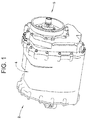
FIG. 1 depicts an integrated drive generator including a differential gear system having a ring gear, in accordance with an exemplary embodiment; -
FIG. 2 depicts a generator and a differential gear system, in accordance with an exemplary embodiment; -
FIG. 3 depicts a partially exploded view of the differential gear system ofFIG. 2 ; -
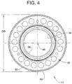
FIG. 4 depicts the ring gear ofFIG. 2 ; -
FIG. 5 depicts a plurality of gear teeth on an outer diametric edge of the ring gear ofFIG. 4 ; and -
FIG. 6 depicts a plurality of gear teeth formed in an inner diametric wall of the ring gear ofFIG. 4 . - A detailed description of one or more embodiments of the disclosed apparatus and method are presented herein by way of exemplification and not limitation with reference to the Figures.
- An integrated drive generator (IDG), in accordance with an exemplary embodiment, is indicated generally at 2, in
FIGs. 1-3 . IDG 2 includes a housing 4 that surrounds aninput system 5 operatively coupled to a variable speed drive source (not shown), agenerator 6, and an epicyclicdifferential gear system 8 coupled to ahydraulic system 9. As will be detailed more fully below, epicyclicdifferential gear system 8 converts a variable speed input from the variable speed drive source into a constant speed output employed to drivegenerator 6. In accordance with an aspect of an exemplary embodiment, the variable speed drive source takes the form of an aircraft engine. However, it should be understood, that the variable speed drive source may take on a variety of forms. - Epicyclic
differential gear system 8 includes an input drivengear 10 coupled toinput system 5 and an output orring gear 11.Ring gear 11 engages with a drivengear 12 ongenerator 6.Ring gear 11 is also coupled to acarrier 13. Carrier 13 also supports aplanet gear system 14 and asun gear 16. Sungear 16 is operatively connected tohydraulic system 9. Planetgear system 14 includes afirst planet gear 18, asecond planet gear 19, and athird planet gear 20. First, second, and third planet gears 18-20 are supported for rotation between a first planet gear support 22 and a secondplanet gear support 23 ofcarrier 13. - As each planet gear 18-20 is substantially similarly formed, a detailed description will follow with reference to
planet gear 18 with an understanding that planet gears 19 and 20 include similar structure. Planetgear 18 includes aplanet gear body 25 including a plurality ofplanet gear teeth 27. Planetgear 18 also includes first and second, opposingthrust surfaces 29 and 30.Thrust surfaces 29 and 30 are formed at an inward end of corresponding first and second axles orbushings Thrust surfaces 29 and 30 axiallytrap planet gear 18 between first and second planet gear supports 22 and 23. - Reference will now follow to
FIGs. 4-6 in describingring gear 11 in accordance with an exemplary embodiment.Ring gear 11 includes aring gear body 40 having an outerdiametric edge 42 and an innerdiametric wall 44 having acenter 46. Outerdiametric edge 42 includes a plurality ofouter gear teeth 50.Outer gear teeth 50 are 129 in number, in accordance with an exemplary embodiment. Innerdiametric wall 44 includes a plurality ofinner gear teeth 54.Inner gear teeth 54 are 63 in number. - In accordance with an exemplary embodiment,
ring gear 11 includes a root diameter (RD) or a diameter ofring gear body 40 defined betweenbase portions 60 of opposing ones ofouter gear teeth 50 throughcenter 46. In accordance with an aspect of an exemplary embodiment, the root diameter ofouter gear teeth 50 is between about 6.302-inch (16.007-cm) and about 6.315-inch (16.04-cm). In accordance with another aspect of an exemplary embodiment, the root diameter is about 6.315-inch (16.04-cm). In further accordance with an exemplary embodiment,outer gear teeth 50 include a pitch diameter (PD) of about 6.45-inch (16.38-cm). - In accordance with yet another aspect of an exemplary embodiment,
inner gear teeth 54 include a root diameter (RD) of between about 3.280-inch (8.33-cm) and about 3.293-inch (8.364-cm). In further accordance with an aspect of an exemplary embodiment,inner gear teeth 54 include a root diameter of about 3.280-inch (8.33-cm). In still further accordance with an aspect of an exemplary embodiment,inner gear teeth 54 include a pitch diameter (PD) of about 3.150-inch (8.001-cm). - In accordance with another aspect of an exemplary embodiment,
outer gear teeth 50 define an outer diameter (OD) of thering gear body 40 of between about 6.550-inch (16.637-cm) and about 6.555-inch (16.649-cm). In accordance with another aspect of an exemplary embodiment,outer gear teeth 50 define an outer diameter of thering gear body 40 of about 6.550-inch (16.637-cm). In accordance with another aspect of an exemplary embodiment,inner gear teeth 54 define an inner diameter of between about 3.070-inch (7.798-cm) and about 3.073-inch (7.805-cm). In accordance with still yet another aspect of an exemplary embodiment,inner gear teeth 54 define an inner diameter of about 3.070-inch (7.798-cm). Thering gear 11, in accordance with an exemplary embodiment, provides a desired constant speed output togenerator 6 while maintaining a desired form factor that is accommodated by housing 4. - The terminology used herein is for the purpose of describing particular embodiments only and is not intended to be limiting of the present disclosure. As used herein, the singular forms "a", "an" and "the" are intended to include the plural forms as well, unless the context clearly indicates otherwise. It will be further understood that the terms "comprises" and/or "comprising," when used in this specification, specify the presence of stated features, integers, steps, operations, elements, and/or components, but do not preclude the presence or addition of one more other features, integers, steps, operations, element components, and/or groups thereof.
- The term "about" is intended to include the degree of error associated with measurement of the particular quantity based upon the equipment available at the time of filing the application. For example, "about" can include a range of ± 8% or 5%, or 2% of a given value.
- While the present disclosure has been described with reference to an exemplary embodiment or embodiments, it will be understood by those skilled in the art that various changes may be made without departing from the scope of the present disclosure. In addition, many modifications may be made to adapt a particular situation or material to the teachings of the present disclosure without departing from the essential scope thereof. Therefore, it is intended that the present disclosure not be limited to the particular embodiment disclosed as the best mode contemplated for carrying out this present disclosure, but that the present disclosure will include all embodiments falling within the scope of the claims.
Claims (15)
- A ring gear (11) for an integrated drive generator (2) (IDG) comprising:a ring gear body (40) including an outer diametric edge and an inner diametric wall, the outer diametric edge including 129 gear teeth.
- The ring gear according to claim 1, wherein the 129 gear teeth include a root diameter of between about 6.302-inch (16.00-cm) and about 6.315-inch (16.04-cm).
- The ring gear according to claim 2, wherein the 129 gear teeth include a root diameter of about 6.315-inch (16.04-cm).
- The ring gear according to claim 1, wherein the 129 gear teeth include a pitch diameter of about 6.45-inch (16.38-cm).
- The ring gear according to any preceding claim, wherein the inner diametric wall includes 63 gear teeth.
- The ring gear according to claim 5, wherein the 63 gear teeth include a root diameter of between about 3.280-inch (8.33-cm) and about 3.293-inch (8.364-cm).
- The ring gear according to claim 5, wherein the 63 gear teeth include a pitch diameter of about 3.150-inch (8.001-cm).
- The ring gear according to any preceding claim, wherein the 129 gear teeth define an outer diameter of the ring gear body of between about 6.550-inch (16.637-cm) and about 6.555-inch (16.649-cm).
- The ring gear according to claim 8, wherein the 129 gear teeth define an outer diameter of the ring gear body of about 6.550-inch (16.637-cm).
- An integrated drive generator (2) (IDG) comprising:a housing (4); anda differential gear system (8) arranged within the housing, the differential gear system including the ring gear of claim 1.
- The integrated drive generator according to claim 10, wherein the 129 gear teeth include a root diameter of between about 6.315-inch (16.04-cm) and about 6.328-inch (16.07-cm).
- The integrated drive generator according to claim 10, wherein the 129 gear teeth include a pitch diameter of about 6.45-inch (16.38-cm).
- The integrated drive member according to any of claims 10-12, wherein the inner diametric wall includes 63 gear teeth.
- The integrated drive generator according to claim 13, wherein the 63 gear teeth include a root diameter of between about 3.280-inch (8.33-cm) and about 3.293-inch (8.364-cm).
- The integrated drive generator according to claim 13, wherein the 63 gear teeth include a pitch diameter of about 3.150-inch (8.001-cm).
Applications Claiming Priority (1)
| Application Number | Priority Date | Filing Date | Title |
|---|---|---|---|
| US14/677,590 US20160290489A1 (en) | 2015-04-02 | 2015-04-02 | Ring gear for an integrated drive generator |
Publications (2)
| Publication Number | Publication Date |
|---|---|
| EP3076052A2 true EP3076052A2 (en) | 2016-10-05 |
| EP3076052A3 EP3076052A3 (en) | 2017-04-05 |
Family
ID=55697041
Family Applications (1)
| Application Number | Title | Priority Date | Filing Date |
|---|---|---|---|
| EP16163674.1A Withdrawn EP3076052A3 (en) | 2015-04-02 | 2016-04-04 | Ring gear for an integrated drive generator |
Country Status (2)
| Country | Link |
|---|---|
| US (1) | US20160290489A1 (en) |
| EP (1) | EP3076052A3 (en) |
Families Citing this family (2)
| Publication number | Priority date | Publication date | Assignee | Title |
|---|---|---|---|---|
| IT201800003230A1 (en) | 2018-03-02 | 2019-09-02 | Ge Avio Srl | NON-AXIAL SYMMETRIC GEAR |
| DE102021208662B4 (en) * | 2021-08-10 | 2023-03-02 | Zf Friedrichshafen Ag | Gear wheel for reducing structure-borne noise in electric drives |
Family Cites Families (8)
| Publication number | Priority date | Publication date | Assignee | Title |
|---|---|---|---|---|
| US3043090A (en) * | 1959-08-03 | 1962-07-10 | Edward V Sundt | Electric clock |
| US4252035A (en) * | 1978-08-11 | 1981-02-24 | Sundstrand Corporation | Integrated drive-generator system |
| US4734590A (en) * | 1986-12-30 | 1988-03-29 | Sundstrand Corporation | Integrated drive generator with common center line |
| JP3440287B2 (en) * | 1999-12-01 | 2003-08-25 | 川崎重工業株式会社 | Constant speed driving method and constant speed driving apparatus for aircraft generator |
| US8226522B2 (en) * | 2008-12-29 | 2012-07-24 | Hamilton Sundstrand Corporation | Coupling for generator/starter |
| US8622869B2 (en) * | 2011-12-28 | 2014-01-07 | George Dimitri Mourani | Drive train transmission |
| US9154011B2 (en) * | 2012-07-06 | 2015-10-06 | Hamilton Sundstrand Corporation | Integrated drive generator housing |
| FR3008463B1 (en) * | 2013-07-10 | 2015-08-07 | Hispano Suiza Sa | COMPACT DRIVE HOUSING STRUCTURE FOR AIRCRAFT TURBOMACHINE |
-
2015
- 2015-04-02 US US14/677,590 patent/US20160290489A1/en not_active Abandoned
-
2016
- 2016-04-04 EP EP16163674.1A patent/EP3076052A3/en not_active Withdrawn
Non-Patent Citations (1)
| Title |
|---|
| None |
Also Published As
| Publication number | Publication date |
|---|---|
| EP3076052A3 (en) | 2017-04-05 |
| US20160290489A1 (en) | 2016-10-06 |
Similar Documents
| Publication | Publication Date | Title |
|---|---|---|
| US20160327134A1 (en) | Gearbox And Drive Arrangement With A Gearbox | |
| EP3372808A3 (en) | Geared turbofan | |
| EP1895158A3 (en) | Method for operating a wind farm with a synchronous generator and a differential drive | |
| EP2629407A1 (en) | Electrical generator for rotating structure | |
| EP3085994A1 (en) | Harmonic gear drive | |
| US20160290489A1 (en) | Ring gear for an integrated drive generator | |
| US9759305B2 (en) | Planet gear for an integrated drive generator | |
| CA2954108C (en) | Planetary gear assembly | |
| EP2778479A3 (en) | Supercharger | |
| US10344845B2 (en) | Sun gear for an integrated drive generator | |
| EP1382797A3 (en) | Fluid machine flow path with increased stage contraction ratios | |
| US20120129642A1 (en) | Anti-rotation pin for a planetary gear utilizing a two-piece carrier | |
| US9160222B1 (en) | Apparatus with power generators driven by electric motors | |
| EP0189518B1 (en) | Toothed gearing | |
| EP2873892A1 (en) | Continuous and reversible mechanical gear system | |
| WO2015091406A1 (en) | Planetary gear, wind generator comprising a planetary gear and use of a planetary gear | |
| CN206419462U (en) | Gear case assembly | |
| US9470302B1 (en) | Accessory drive gear for a differential | |
| KR102133065B1 (en) | Transmission arrangement for a ship's drive and ship's drive with a transmission arrangement | |
| EP2677171A3 (en) | Wind energy system with a coupling between the planetary gear and generator to compensating for axial, radial and angular displacement | |
| US9695926B2 (en) | Accessory drive gear hub for a differential | |
| EP3135904A1 (en) | Windmill driving apparatus, windmill driving system, and reduction gear | |
| EP2908029B1 (en) | Electric generator oil pump driven gear | |
| EP3467350A1 (en) | Trim ring gear for integrated drive generator | |
| DK201970782A1 (en) | Wind turbine power transmission system |
Legal Events
| Date | Code | Title | Description |
|---|---|---|---|
| PUAI | Public reference made under article 153(3) epc to a published international application that has entered the european phase |
Free format text: ORIGINAL CODE: 0009012 |
|
| AK | Designated contracting states |
Kind code of ref document: A2 Designated state(s): AL AT BE BG CH CY CZ DE DK EE ES FI FR GB GR HR HU IE IS IT LI LT LU LV MC MK MT NL NO PL PT RO RS SE SI SK SM TR |
|
| AX | Request for extension of the european patent |
Extension state: BA ME |
|
| PUAL | Search report despatched |
Free format text: ORIGINAL CODE: 0009013 |
|
| AK | Designated contracting states |
Kind code of ref document: A3 Designated state(s): AL AT BE BG CH CY CZ DE DK EE ES FI FR GB GR HR HU IE IS IT LI LT LU LV MC MK MT NL NO PL PT RO RS SE SI SK SM TR |
|
| AX | Request for extension of the european patent |
Extension state: BA ME |
|
| RIC1 | Information provided on ipc code assigned before grant |
Ipc: F16H 55/17 20060101AFI20170301BHEP |
|
| STAA | Information on the status of an ep patent application or granted ep patent |
Free format text: STATUS: REQUEST FOR EXAMINATION WAS MADE |
|
| 17P | Request for examination filed |
Effective date: 20171005 |
|
| RBV | Designated contracting states (corrected) |
Designated state(s): AL AT BE BG CH CY CZ DE DK EE ES FI FR GB GR HR HU IE IS IT LI LT LU LV MC MK MT NL NO PL PT RO RS SE SI SK SM TR |
|
| STAA | Information on the status of an ep patent application or granted ep patent |
Free format text: STATUS: EXAMINATION IS IN PROGRESS |
|
| 17Q | First examination report despatched |
Effective date: 20180717 |
|
| STAA | Information on the status of an ep patent application or granted ep patent |
Free format text: STATUS: THE APPLICATION IS DEEMED TO BE WITHDRAWN |
|
| 18D | Application deemed to be withdrawn |
Effective date: 20190129 |