EP3075972A1 - Valve opening and closing timing control device - Google Patents
Valve opening and closing timing control device Download PDFInfo
- Publication number
- EP3075972A1 EP3075972A1 EP14865788.5A EP14865788A EP3075972A1 EP 3075972 A1 EP3075972 A1 EP 3075972A1 EP 14865788 A EP14865788 A EP 14865788A EP 3075972 A1 EP3075972 A1 EP 3075972A1
- Authority
- EP
- European Patent Office
- Prior art keywords
- rotating body
- circumferential member
- driven rotating
- outer circumferential
- inner circumferential
- Prior art date
- Legal status (The legal status is an assumption and is not a legal conclusion. Google has not performed a legal analysis and makes no representation as to the accuracy of the status listed.)
- Granted
Links
- XEEYBQQBJWHFJM-UHFFFAOYSA-N Iron Chemical compound [Fe] XEEYBQQBJWHFJM-UHFFFAOYSA-N 0.000 claims abstract description 40
- 230000000979 retarding effect Effects 0.000 claims abstract description 37
- 239000000463 material Substances 0.000 claims abstract description 35
- 230000008878 coupling Effects 0.000 claims abstract description 27
- 238000010168 coupling process Methods 0.000 claims abstract description 27
- 238000005859 coupling reaction Methods 0.000 claims abstract description 27
- 239000012530 fluid Substances 0.000 claims abstract description 27
- 238000000638 solvent extraction Methods 0.000 claims abstract description 24
- 229910052742 iron Inorganic materials 0.000 claims abstract description 20
- 238000004891 communication Methods 0.000 claims description 16
- 238000002485 combustion reaction Methods 0.000 claims description 10
- 238000007599 discharging Methods 0.000 abstract description 4
- 238000005192 partition Methods 0.000 abstract 1
- 239000010720 hydraulic oil Substances 0.000 description 10
- XAGFODPZIPBFFR-UHFFFAOYSA-N aluminium Chemical compound [Al] XAGFODPZIPBFFR-UHFFFAOYSA-N 0.000 description 9
- 229910052782 aluminium Inorganic materials 0.000 description 9
- 230000007246 mechanism Effects 0.000 description 6
- 238000005266 casting Methods 0.000 description 4
- 239000003921 oil Substances 0.000 description 4
- 238000005516 engineering process Methods 0.000 description 3
- 229910000838 Al alloy Inorganic materials 0.000 description 2
- 238000003780 insertion Methods 0.000 description 2
- 230000037431 insertion Effects 0.000 description 2
- 229910000831 Steel Inorganic materials 0.000 description 1
- 230000005540 biological transmission Effects 0.000 description 1
- 230000006835 compression Effects 0.000 description 1
- 238000007906 compression Methods 0.000 description 1
- 230000007423 decrease Effects 0.000 description 1
- 239000003562 lightweight material Substances 0.000 description 1
- 239000010705 motor oil Substances 0.000 description 1
- 230000009467 reduction Effects 0.000 description 1
- 239000011347 resin Substances 0.000 description 1
- 229920005989 resin Polymers 0.000 description 1
- 230000004044 response Effects 0.000 description 1
- 230000003068 static effect Effects 0.000 description 1
- 239000010959 steel Substances 0.000 description 1
Images




Classifications
-
- F—MECHANICAL ENGINEERING; LIGHTING; HEATING; WEAPONS; BLASTING
- F01—MACHINES OR ENGINES IN GENERAL; ENGINE PLANTS IN GENERAL; STEAM ENGINES
- F01L—CYCLICALLY OPERATING VALVES FOR MACHINES OR ENGINES
- F01L1/00—Valve-gear or valve arrangements, e.g. lift-valve gear
- F01L1/34—Valve-gear or valve arrangements, e.g. lift-valve gear characterised by the provision of means for changing the timing of the valves without changing the duration of opening and without affecting the magnitude of the valve lift
- F01L1/344—Valve-gear or valve arrangements, e.g. lift-valve gear characterised by the provision of means for changing the timing of the valves without changing the duration of opening and without affecting the magnitude of the valve lift changing the angular relationship between crankshaft and camshaft, e.g. using helicoidal gear
- F01L1/3442—Valve-gear or valve arrangements, e.g. lift-valve gear characterised by the provision of means for changing the timing of the valves without changing the duration of opening and without affecting the magnitude of the valve lift changing the angular relationship between crankshaft and camshaft, e.g. using helicoidal gear using hydraulic chambers with variable volume to transmit the rotating force
-
- F—MECHANICAL ENGINEERING; LIGHTING; HEATING; WEAPONS; BLASTING
- F01—MACHINES OR ENGINES IN GENERAL; ENGINE PLANTS IN GENERAL; STEAM ENGINES
- F01L—CYCLICALLY OPERATING VALVES FOR MACHINES OR ENGINES
- F01L1/00—Valve-gear or valve arrangements, e.g. lift-valve gear
- F01L1/34—Valve-gear or valve arrangements, e.g. lift-valve gear characterised by the provision of means for changing the timing of the valves without changing the duration of opening and without affecting the magnitude of the valve lift
- F01L1/344—Valve-gear or valve arrangements, e.g. lift-valve gear characterised by the provision of means for changing the timing of the valves without changing the duration of opening and without affecting the magnitude of the valve lift changing the angular relationship between crankshaft and camshaft, e.g. using helicoidal gear
- F01L1/348—Valve-gear or valve arrangements, e.g. lift-valve gear characterised by the provision of means for changing the timing of the valves without changing the duration of opening and without affecting the magnitude of the valve lift changing the angular relationship between crankshaft and camshaft, e.g. using helicoidal gear by means acting on timing belts or chains
-
- F—MECHANICAL ENGINEERING; LIGHTING; HEATING; WEAPONS; BLASTING
- F01—MACHINES OR ENGINES IN GENERAL; ENGINE PLANTS IN GENERAL; STEAM ENGINES
- F01L—CYCLICALLY OPERATING VALVES FOR MACHINES OR ENGINES
- F01L1/00—Valve-gear or valve arrangements, e.g. lift-valve gear
- F01L1/34—Valve-gear or valve arrangements, e.g. lift-valve gear characterised by the provision of means for changing the timing of the valves without changing the duration of opening and without affecting the magnitude of the valve lift
- F01L1/344—Valve-gear or valve arrangements, e.g. lift-valve gear characterised by the provision of means for changing the timing of the valves without changing the duration of opening and without affecting the magnitude of the valve lift changing the angular relationship between crankshaft and camshaft, e.g. using helicoidal gear
- F01L1/3442—Valve-gear or valve arrangements, e.g. lift-valve gear characterised by the provision of means for changing the timing of the valves without changing the duration of opening and without affecting the magnitude of the valve lift changing the angular relationship between crankshaft and camshaft, e.g. using helicoidal gear using hydraulic chambers with variable volume to transmit the rotating force
- F01L2001/34423—Details relating to the hydraulic feeding circuit
-
- F—MECHANICAL ENGINEERING; LIGHTING; HEATING; WEAPONS; BLASTING
- F01—MACHINES OR ENGINES IN GENERAL; ENGINE PLANTS IN GENERAL; STEAM ENGINES
- F01L—CYCLICALLY OPERATING VALVES FOR MACHINES OR ENGINES
- F01L1/00—Valve-gear or valve arrangements, e.g. lift-valve gear
- F01L1/34—Valve-gear or valve arrangements, e.g. lift-valve gear characterised by the provision of means for changing the timing of the valves without changing the duration of opening and without affecting the magnitude of the valve lift
- F01L1/344—Valve-gear or valve arrangements, e.g. lift-valve gear characterised by the provision of means for changing the timing of the valves without changing the duration of opening and without affecting the magnitude of the valve lift changing the angular relationship between crankshaft and camshaft, e.g. using helicoidal gear
- F01L1/3442—Valve-gear or valve arrangements, e.g. lift-valve gear characterised by the provision of means for changing the timing of the valves without changing the duration of opening and without affecting the magnitude of the valve lift changing the angular relationship between crankshaft and camshaft, e.g. using helicoidal gear using hydraulic chambers with variable volume to transmit the rotating force
- F01L2001/34423—Details relating to the hydraulic feeding circuit
- F01L2001/34426—Oil control valves
-
- F—MECHANICAL ENGINEERING; LIGHTING; HEATING; WEAPONS; BLASTING
- F01—MACHINES OR ENGINES IN GENERAL; ENGINE PLANTS IN GENERAL; STEAM ENGINES
- F01L—CYCLICALLY OPERATING VALVES FOR MACHINES OR ENGINES
- F01L1/00—Valve-gear or valve arrangements, e.g. lift-valve gear
- F01L1/34—Valve-gear or valve arrangements, e.g. lift-valve gear characterised by the provision of means for changing the timing of the valves without changing the duration of opening and without affecting the magnitude of the valve lift
- F01L1/344—Valve-gear or valve arrangements, e.g. lift-valve gear characterised by the provision of means for changing the timing of the valves without changing the duration of opening and without affecting the magnitude of the valve lift changing the angular relationship between crankshaft and camshaft, e.g. using helicoidal gear
- F01L1/3442—Valve-gear or valve arrangements, e.g. lift-valve gear characterised by the provision of means for changing the timing of the valves without changing the duration of opening and without affecting the magnitude of the valve lift changing the angular relationship between crankshaft and camshaft, e.g. using helicoidal gear using hydraulic chambers with variable volume to transmit the rotating force
- F01L2001/3445—Details relating to the hydraulic means for changing the angular relationship
- F01L2001/34453—Locking means between driving and driven members
-
- F—MECHANICAL ENGINEERING; LIGHTING; HEATING; WEAPONS; BLASTING
- F01—MACHINES OR ENGINES IN GENERAL; ENGINE PLANTS IN GENERAL; STEAM ENGINES
- F01L—CYCLICALLY OPERATING VALVES FOR MACHINES OR ENGINES
- F01L1/00—Valve-gear or valve arrangements, e.g. lift-valve gear
- F01L1/34—Valve-gear or valve arrangements, e.g. lift-valve gear characterised by the provision of means for changing the timing of the valves without changing the duration of opening and without affecting the magnitude of the valve lift
- F01L1/344—Valve-gear or valve arrangements, e.g. lift-valve gear characterised by the provision of means for changing the timing of the valves without changing the duration of opening and without affecting the magnitude of the valve lift changing the angular relationship between crankshaft and camshaft, e.g. using helicoidal gear
- F01L1/3442—Valve-gear or valve arrangements, e.g. lift-valve gear characterised by the provision of means for changing the timing of the valves without changing the duration of opening and without affecting the magnitude of the valve lift changing the angular relationship between crankshaft and camshaft, e.g. using helicoidal gear using hydraulic chambers with variable volume to transmit the rotating force
- F01L2001/3445—Details relating to the hydraulic means for changing the angular relationship
- F01L2001/34483—Phaser return springs
-
- F—MECHANICAL ENGINEERING; LIGHTING; HEATING; WEAPONS; BLASTING
- F01—MACHINES OR ENGINES IN GENERAL; ENGINE PLANTS IN GENERAL; STEAM ENGINES
- F01L—CYCLICALLY OPERATING VALVES FOR MACHINES OR ENGINES
- F01L2303/00—Manufacturing of components used in valve arrangements
Definitions
- the present invention relates to a valve opening/closing timing control device that includes: a driving rotating body that rotates in synchronization with a crankshaft of an internal combustion engine; and a driven rotating body that rotates in synchronization with a camshaft for opening/closing a valve of the internal combustion engine.
- Patent Document 1 discloses a valve opening/closing timing control device that includes a driven rotating body that is configured with: a cylindrical outer circumferential member that is made of a lightweight aluminum-based material; and a cylindrical inner circumferential member that is made of an iron-based material having a higher strength than the aluminum-based material, the outer circumferential member and the inner circumferential member being integrated into one piece so as to have the same rotational axis.
- This valve opening/closing timing control device is configured to control the rotation phase of the driven rotating body relative to the driving rotating body by supplying/discharging a pressurized fluid to/from an advancing chamber or a retarding chamber from the camshaft side via an advancing channel or a retarding channel.
- Patent Document 1 JP 2000-161028A
- an aluminum-based material is used in the outer circumferential member, and therefore the strength of the driven rotating body is lower than the strength of a prior driven rotating body that is configured with only an iron-based material.
- only a pressurized fluid supply channel and an insertion hole for a bolt for connecting the inner circumferential member to the camshaft are formed in the inner circumferential member, and the amount of reduction in the volume of the inner circumferential member is limited. Therefore, although the overall strength of the driven rotating body according to the above-described conventional technology is reduced, the strength is maintained at a required level.
- a so-called front feed type driven rotating body to/from which a pressurized fluid is supplied/discharged from the opposite side to the camshaft.
- a fixed shaft portion that supplies the pressurized fluid is inserted into a recessed portion that is formed in the center of the inner circumferential member.
- the fixed shaft portion is likely to be large in size because the fixed shaft portion is provided with a channel for supplying/discharging the pressurized fluid, as well as a seal member or the like that is to be located at the boundary between the fixed shaft portion and the inner circumferential member.
- front feed type valve opening/closing timing control devices still have points to be improved, e.g., it is difficult to ensure the strength if an aluminum-based material is used in a portion of the driven rotating body.
- the present invention has been made in view of the above-described situation, and aims to provide a valve opening/closing timing control device that makes it easy to reduce the weight of the driven rotating body while ensuring the strength thereof, despite having a front feed type structure in which the inner circumference side of the driven rotating body is supported by the fixed shaft portion.
- a characteristic configuration of a valve opening/closing timing control device lies in that the valve opening/closing timing control device includes: a driving rotating body that rotates in synchronization with a crankshaft of an internal combustion engine; a driven rotating body that is located on an inner circumference side of the driving rotating body so as to be relatively rotatable, and that rotates in synchronization with a camshaft for opening/closing a valve of the internal combustion engine; a fixed shaft portion by which an inner circumferential part of the driven rotating body is supported so as to be rotatable about a rotational axis that is the same as a rotational axis of the driving rotating body; a fluid pressure chamber that is formed between the driving rotating body and the driven rotating body; an advancing chamber and a retarding chamber that are formed by partitioning the fluid pressure chamber with a partitioning portion that is provided on an outer circumference side of the driven rotating body; an advancing channel that is in communication with the advancing chamber, and a retarding channel that
- the valve opening/closing timing control device having this configuration includes: a fixed shaft portion by which an inner circumferential part of the driven rotating body is supported so as to be rotatable about a rotational axis that is the same as a rotational axis of the driving rotating body; and a phase control unit for controlling a rotation phase of the driven rotating body relative to the driving rotating body such that a pressurized fluid is selectively supplied to or discharged from the advancing chamber or the retarding chamber via an inside of the fixed shaft portion and via the advancing channel or the retarding channel.
- the inner circumferential part of the driven rotating body is supported by the fixed shaft portion, which tends to have a large diameter because a pressurized fluid is selectively supplied to or discharged from the advancing chamber or the retarding chamber via the inside of the fixed shaft portion, and via the advancing channel or the retarding channel.
- the driven rotating body configured with the outer circumferential member and the inner circumferential member that are unified with each other and have the same rotational axis, if the wall thickness of the inner circumferential member made of an iron-based material is increased in order to ensure the strength of the driven rotating body, the wall thickness of the outer circumferential member is reduced, and it is difficult to reduce the weight of the driven rotating body.
- the driven rotating body has: an inner circumferential member that has a cylindrical portion into which the fixed shaft portion is inserted, and a coupling plate portion for coupling the camshaft to one end portion of the cylindrical portion, the cylindrical portion and the coupling plate portion being integrated with each other; and a cylindrical outer circumferential member that is located on an outer circumference side of the inner circumferential member and is provided with the partitioning portion.
- the outer circumferential member is provided with the inner circumferential member in a unified manner so as to have the same rotational axis, the inner circumferential member is formed with an iron-based material, and the outer circumferential member is formed with a material that is lighter in weight than the iron-based material.
- the inner circumferential member that has a coupling plate portion integrated therewith for coupling the camshaft to one end portion of the cylindrical portion, and has a high shape rigidity, is formed with an iron-based material in addition to the cylindrical portion into which the fixed shaft portion is inserted, and the outer circumferential member is formed with a material that is lighter in weight than the iron-based material.
- valve opening/closing timing control device having this configuration makes it easier to reduce the weight of the driven rotating body while ensuring the strength thereof, despite having a structure in which the inner circumference side of the driven rotating body is supported by the fixed shaft portion.
- Another characteristic configuration of one aspect of the present invention lies in that an opening part of the cylindrical portion extends further in a direction along the rotational axis than a part which is provided with the outer circumferential member in a unified manner.
- This configuration makes it possible to increase the rigidity of the opening part of the cylindrical portion, and to prevent the cylindrical portion from deforming due to a difference in the coefficient of thermal expansion of the outer circumferential member and the inner circumferential member, for example.
- the cylindrical portion has: a small-diameter portion that is provided with the coupling plate portion; and a large-diameter portion that is provided with a protruding part provided within a space defined inside the partitioning portion, that is continuous with the small-diameter part, and that has external dimensions that are greater than external dimensions of the small-diameter portion, the small-diameter portion and the large-diameter portion being integrated with each other, and the outer circumferential member is provided on the outer circumference side of the large-diameter portion in a unified manner.
- Another characteristic configuration of one aspect of the present invention lies in that two end surfaces of the large-diameter portion in a direction along the rotational axis have a part that is in contact with the driving rotating body, and a length of the outer circumferential member in the direction along the rotational axis is shorter than a length of an interval between the two end surfaces of the large-diameter portion in the direction along the rotational axis.
- FIG. 1 to FIG. 5 show a valve opening/closing timing control device A according to one aspect of the present invention, which is to be installed to a gasoline engine (internal combustion engine) E for automobiles.
- the valve opening/closing timing control device A includes: a housing 1 serving as a "driving rotating body” that rotates in synchronization with a crankshaft E1 of an engine E; an inner rotor 3 serving as a "driven rotating body” that is located on the inner circumference side of the housing 1 so as to be relatively rotatable, and that rotates in synchronization with a camshaft 2 for opening/closing a valve of the engine E; a fixed shaft portion 4 by which an inner circumferential part of the inner rotor 3 is supported so as to be rotatable about a rotational axis that is the same as a rotational axis X of the housing 1; fluid pressure chambers 5 that are formed between the housing 1 and the inner rotor 3
- the housing 1 includes: an outer rotor 1a having a cylindrical outer circumferential shape; a front plate 1 b that is located on the front side of the outer rotor 1 a; and a rear plate 1c that is located on the rear side of the outer rotor 1 a, which are fixed to each other with coupling bolts 1 d and are integrated into one piece.
- the outer rotor 1 a and the front plate 1 b are formed with an aluminum-based material such as an aluminum alloy that is lighter in weight than iron-based materials.
- the rear plate 1c includes a sprocket 1e that is provided on the outer circumference side of the rear plate 1 c integrally therewith, and is formed with an iron-based material such as steel.
- a power transmission member E2 such as a timing chain or a timing belt is wound around the sprocket 1 e and a sprocket that is attached to the crankshaft E1, and the housing 1 rotates in the direction indicated by an arrow S shown in FIG. 2 as the engine E is driven.
- the inner rotor 3 is fixed to a tip portion of the camshaft 2 that is provided with a cam (not shown in the drawings) that controls opening/closing of an intake valve or an exhaust valve of the engine E.
- the inner rotor 3 is driven to rotate in the direction indicated by the arrow S along with the rotation of the housing 1.
- the inner rotor 3 is provided with a recessed portion 8 that has a cylindrical inner circumferential surface 8a that is coaxial with the rotational axis X, and a coupling plate portion 8b for coupling with the camshaft 2.
- the inner rotor 3 and the camshaft 2 are fixed to each other and are integrated into one piece by screwing a bolt 10, which has been inserted into the coupling plate portion 8b, into the camshaft 2 coaxially therewith.
- a torsion coil spring 18 that biases the rotation phase of the inner rotor 3 relative to the housing 1 toward the advance side is attached so as to span the inner rotor 3 and the rear plate 1 c.
- a plurality of protruding portions 9 that protrude inward in the radial direction are formed on the inner circumference side of the outer rotor 1 a integrally therewith, at positions that are separated from each other in the rotation direction.
- Each protruding portion 9 is provided such that a protruding end portion thereof is slidable along the outer circumferential surface of the inner rotor 3 with a seal member 9a therebetween.
- Four fluid pressure chambers 5 are formed between the protruding portions 9 that are adjacent to each other in the rotation direction, and between the outer rotor 1 a and the inner rotor 3.
- the coupling bolts 1d are respectively inserted through the protruding portions 9, by which the outer rotor 1 a, the front plate 1 b, and the rear plate 1 c are fixed to each other and are integrated into one piece.
- a plurality of partitioning portions 6 that protrude outward in the radial direction are formed at positions that respectively face the fluid pressure chambers 5 on the outer circumference side of the inner rotor 3 integrally therewith and are separated from each other in the rotation direction.
- Each partitioning portion 6 is provided such that a protruding end portion thereof is slidable along the inner circumferential surface of the outer rotor 1a with a seal member 6a therebetween.
- Each fluid pressure chamber 5 is partitioned by the corresponding partitioning portion 6 into an advancing chamber 5a and a retarding chamber 5b that are adjacent to each other in the rotation direction.
- advancing channels 11a that each have a circular cross section and are in communication with the advancing chambers 5a
- retarding channels 11 b that each have a circular cross section and are in communication with the retarding chambers 5b, are formed to penetrate through the inner rotor 3 in the radial direction of rotation and to be in communication with the inner circumference side, specifically the recessed portion 8, of the inner rotor 3.
- Hydraulic oil is supplied to or discharged from the advancing chambers 5a via the advancing channels 11a, and is supplied to or discharged from the retarding chambers 5b via the retarding channels 11 b.
- the advancing channels 11 a and the retarding channels 11 b are formed between the partitioning portions 6 that are adjacent to one another in the rotation direction, so as to be displaced from each other in the direction of the rotational axis X as shown in FIG. 1 , and so as to be out of phase with each other around the rotational axis X as shown in FIG. 2 .
- the advancing channels 11 a are in communication with the recessed portion 8 at positions that are on the rear plate 1c side and that face a space between the fixed shaft portion 4 and the coupling plate portion 8b, and the retarding channels 11 b are in communication with the recessed portion 8 at positions that are closer to the front plate 1 b than the advancing channels 11 a are and that face the outer circumferential surface of the fixed shaft portion 4.
- the fixed shaft portion 4 has: an advance-side supply channel 12a serving as a fluid channel that can be in communication with the advancing channels 11a; and a retard-side supply channel 12b serving as a fluid channel that can be in communication with the retarding channels 11 b.
- the advance-side supply channel 12a is in communication with the space between the fixed shaft portion 4 and the coupling plate portion 8b from one end side of the fixed shaft portion 4 in the axial direction thereof, and the retard-side supply channel 12b is in communication with a ring-shaped circumferential groove 13 that is formed in the outer circumferential surface of the fixed shaft portion 4.
- Seal rings 14 that fill the gap between the outer circumferential surface of the fixed shaft portion 4 and the inner circumferential surface 8a of the recessed portion 8 are attached to both sides of the ring-shaped circumferential groove 13 and one end side of the fixed shaft portion 4 in the axial direction.
- a lock mechanism 15 that can switch to a locked state in which the lock mechanism 15 restrains the rotation phase of the inner rotor 3 relative to the housing 1 at the maximum retard position, and to an unlocked state in which the lock mechanism 15 releases the restraint, is provided to span one of the partitioning portions 6 included in the inner rotor 3, and the housing 1.
- the lock mechanism 15 is configured by attaching a lock member 15a to one of the partitioning portions 6 of the inner rotor 3, the lock member 15a having a tip portion that can protrude and retract in the direction along the rotational axis X relative to a recessed portion (not shown in the drawings) formed in the rear plate 1 c.
- the lock mechanism 15 switches to the locked state upon the tip portion of the lock member 15a becoming embedded in the recessed portion of the rear plate 1 c due to the biasing force of a biasing member (not shown in the drawings) such as a compression spring, and switches to the unlocked state upon the tip portion exiting the recessed portion of the rear plate 1c toward the inner rotor 3 side, moving against the biasing force of the biasing member, due to the pressure of the hydraulic oil supplied via a lock oil channel 11c that is in communication with the ring-shaped circumferential groove 13.
- a biasing member such as a compression spring
- the phase control unit 7 includes: an oil pump P that sucks/discharges hydraulic oil within an oil pan 17; a fluid control valve OCV that supplies/discharges hydraulic oil to/from the advance-side supply channel 12a and the retard-side supply channel 12b, and interrupts the supply/discharge of hydraulic oil; and an electronic control unit ECU that controls the actions of the fluid control valve OCV.
- the rotation phase of the inner rotor 3 relative to the housing 1 is displaced in the advance direction (the direction of increasing the capacities of the advancing chambers 5a) indicated by the arrow S1, or in the retard direction (the direction of increasing the capacities of the retarding chambers 5b) indicated by the arrow S2 by a hydraulic oil supplying/discharging operation of the phase control unit 7, and the rotation phase is maintained at a given phase by a hydraulic oil supply/discharge interrupting operation.
- the lock mechanism 15 switches from the locked state to the unlocked state upon hydraulic oil being supplied via the lock oil channel 11c in response to an operation to supply hydraulic oil to the advancing chambers 5a.
- the inner rotor 3 has: a cylindrical inner circumferential member 3b; and a cylindrical outer circumferential member 3a that is located on the outer circumference side of the inner circumferential member 3b, and that are integrated with the partitioning portions 6 provided on the outer circumference side of the cylindrical outer circumferential member 3a.
- the outer circumferential member 3a is provided with the inner circumferential member 3b in a unified manner so as to have the same rotational axis.
- the inner circumferential member 3b has: a cylindrical portion 19 into which the fixed shaft portion 4 is inserted; the coupling plate portion 8b that is located on one end portion of the cylindrical portion 19; and four protruding parts 20 that are respectively provided within spaces that are defined inside the partitioning portions 6 (i.e. respectively embedded in the partitioning portions 6), the cylindrical portion 19, the coupling plate portion 8b, and the protruding parts 20 being integrated with each other, and the inner circumferential member 3b is configured with, for example, a high-strength sintered or forged article that has been formed with an iron-based material.
- the lock member 15a is attached to one of the protruding parts 20.
- the outer circumferential member 3a is formed with a material that is lighter in weight than the iron-based material with which the inner circumferential member 3b is formed, specifically an aluminum-based material such as an aluminum alloy, for example.
- the outer circumferential member 3a is provided on the outer circumference side of the cylindrical portion 19 in a unified manner, in the state of being prevented from rotating, by, using insert casting, enveloping the outer circumferential portion of the inner circumferential member 3b together with the protruding parts 20, with the aluminum-based material with which the outer circumferential member 3a is formed.
- An inner circumferential surface 22 of the opening part 21 is formed to be a tapered surface whose diameter decreases in the direction toward the outer circumferential member 3a side (the deeper side), so as to serve as an insertion guide for the fixed shaft portion 4.
- the cylindrical portion 19 has: a small-diameter portion 23 that has one end portion provided with the coupling plate portion 8b; and a large-diameter portion 24 that is continuous with the small-diameter portion 23 and that has external dimensions that are greater than the external dimensions of the small-diameter portion 23, the small-diameter portion 23 and the large-diameter portion 24 being integrated with each other.
- the large-diameter portion 24 is provided around the small-diameter portion 23 and increases the diameter.
- the large-diameter portion 24 is located on an intermediate portion of the small-diameter portion 23 in the longitudinal direction, and the protruding parts 20 are provided on the outer circumference side of the large-diameter portion 24 integrally therewith.
- the outer circumferential member 3a is provided on the outer circumference side of the large-diameter portion 24 in a unified manner such that the entirety of the large-diameter portion 24 and the protruding parts 20, including both end surfaces that face in the direction along the rotational axis X, are enveloped using insert casting. Therefore, it is possible to increase the external dimensions of the large-diameter portion 24 to be greater than the external dimensions of the small-diameter portion 23, and to approximate the wall thickness of a portion of the outer circumferential member 3a that covers the large-diameter portion 24 to the wall thickness of a portion of the outer circumferential member 3a that covers the protruding parts 20, while further increasing the rigidity of the inner circumferential member 3b.
- FIG. 6 to FIG. 8 show another embodiment of the present invention.
- two end surfaces 25 of the large-diameter portion 24 in the direction along the rotational axis X are formed to be slide-contact surfaces that have portions that are in contact with the front plate 1 b and the rear plate 1 c of the housing 1 along the entire circumference, as shown in FIG. 6 .
- the length of the outer circumferential member 3a is shorter than the length of the interval between the two end surfaces 25 of the large-diameter portion 24.
- the outer circumferential member 3a is provided so as not to protrude further than the two end surfaces 25 in the direction along the rotational axis X, and therefore, when the large-diameter portion 24 is enveloped in the outer circumferential member 3a using insert casting, the aluminum based material that has been fused is unlikely to attach to a slide-contact portion 26 of the small-diameter portion 23 that is in contact with the rear plate 1c.
- the other configurations are the same as those in the first embodiment.
Landscapes
- Engineering & Computer Science (AREA)
- Mechanical Engineering (AREA)
- General Engineering & Computer Science (AREA)
- Valve Device For Special Equipments (AREA)
Abstract
Description
- The present invention relates to a valve opening/closing timing control device that includes: a driving rotating body that rotates in synchronization with a crankshaft of an internal combustion engine; and a driven rotating body that rotates in synchronization with a camshaft for opening/closing a valve of the internal combustion engine.
- In order to reduce the weight of the driven rotating body while ensuring the strength thereof,
Patent Document 1 discloses a valve opening/closing timing control device that includes a driven rotating body that is configured with: a cylindrical outer circumferential member that is made of a lightweight aluminum-based material; and a cylindrical inner circumferential member that is made of an iron-based material having a higher strength than the aluminum-based material, the outer circumferential member and the inner circumferential member being integrated into one piece so as to have the same rotational axis. - This valve opening/closing timing control device is configured to control the rotation phase of the driven rotating body relative to the driving rotating body by supplying/discharging a pressurized fluid to/from an advancing chamber or a retarding chamber from the camshaft side via an advancing channel or a retarding channel.
- Patent Document 1:
JP 2000-161028A - In the above-described conventional valve opening/closing timing control device, an aluminum-based material is used in the outer circumferential member, and therefore the strength of the driven rotating body is lower than the strength of a prior driven rotating body that is configured with only an iron-based material. However, in the case of the above-described conventional technology, only a pressurized fluid supply channel and an insertion hole for a bolt for connecting the inner circumferential member to the camshaft are formed in the inner circumferential member, and the amount of reduction in the volume of the inner circumferential member is limited. Therefore, although the overall strength of the driven rotating body according to the above-described conventional technology is reduced, the strength is maintained at a required level.
- In contrast, there is a so-called front feed type driven rotating body to/from which a pressurized fluid is supplied/discharged from the opposite side to the camshaft. In this case, a fixed shaft portion that supplies the pressurized fluid is inserted into a recessed portion that is formed in the center of the inner circumferential member. However, the fixed shaft portion is likely to be large in size because the fixed shaft portion is provided with a channel for supplying/discharging the pressurized fluid, as well as a seal member or the like that is to be located at the boundary between the fixed shaft portion and the inner circumferential member. Also, it is necessary to secure an area in which a portion of the bolt for coupling with the camshaft can be housed, within the recessed portion of the inner circumferential member. Therefore, it is necessary to form a relatively large recessed portion in the central portion of the inner circumferential member, and consequently the strength of the inner circumferential member is considerably lower than the strength of the above-described conventional technology.
- In this way, front feed type valve opening/closing timing control devices still have points to be improved, e.g., it is difficult to ensure the strength if an aluminum-based material is used in a portion of the driven rotating body.
- The present invention has been made in view of the above-described situation, and aims to provide a valve opening/closing timing control device that makes it easy to reduce the weight of the driven rotating body while ensuring the strength thereof, despite having a front feed type structure in which the inner circumference side of the driven rotating body is supported by the fixed shaft portion.
- A characteristic configuration of a valve opening/closing timing control device according to one aspect of the present invention lies in that the valve opening/closing timing control device includes: a driving rotating body that rotates in synchronization with a crankshaft of an internal combustion engine; a driven rotating body that is located on an inner circumference side of the driving rotating body so as to be relatively rotatable, and that rotates in synchronization with a camshaft for opening/closing a valve of the internal combustion engine; a fixed shaft portion by which an inner circumferential part of the driven rotating body is supported so as to be rotatable about a rotational axis that is the same as a rotational axis of the driving rotating body; a fluid pressure chamber that is formed between the driving rotating body and the driven rotating body; an advancing chamber and a retarding chamber that are formed by partitioning the fluid pressure chamber with a partitioning portion that is provided on an outer circumference side of the driven rotating body; an advancing channel that is in communication with the advancing chamber, and a retarding channel that is in communication with the retarding chamber, the advancing channel and the retarding channel being formed in the driven rotating body; and a phase control unit for controlling a rotation phase of the driven rotating body relative to the driving rotating body such that a pressurized fluid is selectively supplied/discharged to/from the advancing chamber or the retarding chamber via an inside of the fixed shaft portion and via the advancing channel or the retarding channel, and that the driven rotating body has: an inner circumferential member that has a cylindrical portion into which the fixed shaft portion is inserted, and a coupling plate portion for coupling the camshaft to one end portion of the cylindrical portion, the cylindrical portion and the coupling plate portion being integrated with each other; and a cylindrical outer circumferential member that is located on an outer circumference side of the inner circumferential member and is provided with the partitioning portion, the outer circumferential member is provided with the inner circumferential member in a unified manner so as to have the same rotational axis, the inner circumferential member is formed with an iron-based material, and the outer circumferential member is formed with a material that is lighter in weight than the iron-based material.
- The valve opening/closing timing control device having this configuration includes: a fixed shaft portion by which an inner circumferential part of the driven rotating body is supported so as to be rotatable about a rotational axis that is the same as a rotational axis of the driving rotating body; and a phase control unit for controlling a rotation phase of the driven rotating body relative to the driving rotating body such that a pressurized fluid is selectively supplied to or discharged from the advancing chamber or the retarding chamber via an inside of the fixed shaft portion and via the advancing channel or the retarding channel. In other words, the inner circumferential part of the driven rotating body is supported by the fixed shaft portion, which tends to have a large diameter because a pressurized fluid is selectively supplied to or discharged from the advancing chamber or the retarding chamber via the inside of the fixed shaft portion, and via the advancing channel or the retarding channel.
- Therefore, when providing the driven rotating body configured with the outer circumferential member and the inner circumferential member that are unified with each other and have the same rotational axis, if the wall thickness of the inner circumferential member made of an iron-based material is increased in order to ensure the strength of the driven rotating body, the wall thickness of the outer circumferential member is reduced, and it is difficult to reduce the weight of the driven rotating body.
- For this reason, in this configuration, the driven rotating body has: an inner circumferential member that has a cylindrical portion into which the fixed shaft portion is inserted, and a coupling plate portion for coupling the camshaft to one end portion of the cylindrical portion, the cylindrical portion and the coupling plate portion being integrated with each other; and a cylindrical outer circumferential member that is located on an outer circumference side of the inner circumferential member and is provided with the partitioning portion. The outer circumferential member is provided with the inner circumferential member in a unified manner so as to have the same rotational axis, the inner circumferential member is formed with an iron-based material, and the outer circumferential member is formed with a material that is lighter in weight than the iron-based material.
- In other words, in order to ensure the strength of the inner circumferential member when providing the driven rotating body configured with the outer circumferential member and the inner circumferential member that are coaxially unified with each other, the inner circumferential member that has a coupling plate portion integrated therewith for coupling the camshaft to one end portion of the cylindrical portion, and has a high shape rigidity, is formed with an iron-based material in addition to the cylindrical portion into which the fixed shaft portion is inserted, and the outer circumferential member is formed with a material that is lighter in weight than the iron-based material.
- For this reason, it is possible to increase the rigidity of the inner circumferential member that is formed with the iron-based material, without increasing the wall thickness thereof, and to reduce the weight of the driven rotating body while ensuring a large wall thickness of the outer circumferential member that is formed with a lightweight material. Therefore, the valve opening/closing timing control device having this configuration makes it easier to reduce the weight of the driven rotating body while ensuring the strength thereof, despite having a structure in which the inner circumference side of the driven rotating body is supported by the fixed shaft portion.
- Another characteristic configuration of one aspect of the present invention lies in that an opening part of the cylindrical portion extends further in a direction along the rotational axis than a part which is provided with the outer circumferential member in a unified manner.
- This configuration makes it possible to increase the rigidity of the opening part of the cylindrical portion, and to prevent the cylindrical portion from deforming due to a difference in the coefficient of thermal expansion of the outer circumferential member and the inner circumferential member, for example.
- Another characteristic configuration of one aspect of the present invention lies in that the cylindrical portion has: a small-diameter portion that is provided with the coupling plate portion; and a large-diameter portion that is provided with a protruding part provided within a space defined inside the partitioning portion, that is continuous with the small-diameter part, and that has external dimensions that are greater than external dimensions of the small-diameter portion, the small-diameter portion and the large-diameter portion being integrated with each other, and the outer circumferential member is provided on the outer circumference side of the large-diameter portion in a unified manner.
- With this configuration, it is possible to approximate the wall thickness of a portion of the outer circumferential member that covers the large-diameter portion to the wall thickness of a portion of the outer circumferential member that covers the protruding part while further increasing the rigidity of the inner circumferential member, by appropriately setting the external dimensions of the large-diameter portion. For this reason, it is possible to prevent the relative deformation areas of the outer circumferential member relative to the inner circumferential member, which are generated due to, for example, the difference in the coefficient of thermal expansion of the outer circumferential member and the inner circumferential member, from being localized between partitioning portions that are adjacent to each other in the circumferential direction, and to disperse the relative deformation areas to a portion that covers the protruding portion as well. Therefore, it is possible to prevent the outer circumferential member and the inner circumferential member from, for example, being separated from each other at the interface therebetween due to the deformation of the outer circumferential member relative to the inner circumferential member.
- Another characteristic configuration of one aspect of the present invention lies in that two end surfaces of the large-diameter portion in a direction along the rotational axis have a part that is in contact with the driving rotating body, and a length of the outer circumferential member in the direction along the rotational axis is shorter than a length of an interval between the two end surfaces of the large-diameter portion in the direction along the rotational axis.
- With this configuration, it is possible to form the parts of the driven rotating body, which are in contact with the driving rotating body, with an iron-based material, and it is therefore possible to suppress the contacting parts from wearing, and to prevent "rattling" of the driving rotating body and the driven rotating body occurring in the direction along the rotational axis, over a long period.
-
-
FIG. 1 is a vertical cross-sectional view showing a valve opening/closing timing control device according to a first embodiment. -
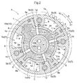
FIG. 2 is a cross-sectional view along a line II-II inFIG. 1 seen in a direction indicated by arrows. -
FIG. 3 is a vertical cross-sectional view of an inner rotor (a driven rotating body). -
FIG. 4 is a perspective view of an inner circumferential member. -
FIG. 5 is a perspective view of the inner rotor. -
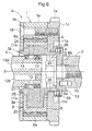
FIG. 6 is a vertical cross-sectional view showing a valve opening/closing timing control device according to a second embodiment. -
FIG. 7 is a perspective view of an inner circumferential member. -
FIG. 8 is a perspective view of an inner rotor. - The following describes embodiments of the present invention with reference to the drawings.
-
FIG. 1 to FIG. 5 show a valve opening/closing timing control device A according to one aspect of the present invention, which is to be installed to a gasoline engine (internal combustion engine) E for automobiles. As shown inFIG. 1 andFIG. 2 , the valve opening/closing timing control device A includes: ahousing 1 serving as a "driving rotating body" that rotates in synchronization with a crankshaft E1 of an engine E; aninner rotor 3 serving as a "driven rotating body" that is located on the inner circumference side of thehousing 1 so as to be relatively rotatable, and that rotates in synchronization with acamshaft 2 for opening/closing a valve of the engine E; afixed shaft portion 4 by which an inner circumferential part of theinner rotor 3 is supported so as to be rotatable about a rotational axis that is the same as a rotational axis X of thehousing 1;fluid pressure chambers 5 that are formed between thehousing 1 and theinner rotor 3; advancingchambers 5a and retardingchambers 5b that are formed by partitioning thefluid pressure chambers 5 with partitioningportions 6 that are provided on the outer circumference side of theinner rotor 3 integrally therewith; advancingchannels 11 a that are in communication with the advancingchambers 5a and retardingchannels 11 b that are in communication with the retardingchambers 5b, the advancingchannels 11 a and the retardingchannels 11 b being formed in theinner rotor 3; and aphase control unit 7 for controlling the rotation phase of theinner rotor 3 relative to thehousing 1 by using hydraulic oil (engine oil) serving as a "pressurized fluid" selectively supplied/discharged to/from the advancingchambers 5a or the retardingchambers 5b via the inside of thefixed shaft portion 4 and via the advancingchannels 11 a or the retardingchannels 11 b. Thecamshaft 2 is rotatably attached to a cylinder head (not shown in the drawings) of the engine E. Thefixed shaft portion 4 is fixed to a static member such as a front cover of the engine E. - The
housing 1 includes: anouter rotor 1a having a cylindrical outer circumferential shape; afront plate 1 b that is located on the front side of theouter rotor 1 a; and arear plate 1c that is located on the rear side of theouter rotor 1 a, which are fixed to each other withcoupling bolts 1 d and are integrated into one piece. Theouter rotor 1 a and thefront plate 1 b are formed with an aluminum-based material such as an aluminum alloy that is lighter in weight than iron-based materials. Therear plate 1c includes asprocket 1e that is provided on the outer circumference side of therear plate 1 c integrally therewith, and is formed with an iron-based material such as steel. - A power transmission member E2 such as a timing chain or a timing belt is wound around the
sprocket 1 e and a sprocket that is attached to the crankshaft E1, and thehousing 1 rotates in the direction indicated by an arrow S shown inFIG. 2 as the engine E is driven. - The
inner rotor 3 is fixed to a tip portion of thecamshaft 2 that is provided with a cam (not shown in the drawings) that controls opening/closing of an intake valve or an exhaust valve of the engine E. Theinner rotor 3 is driven to rotate in the direction indicated by the arrow S along with the rotation of thehousing 1. - The
inner rotor 3 is provided with arecessed portion 8 that has a cylindrical innercircumferential surface 8a that is coaxial with the rotational axis X, and acoupling plate portion 8b for coupling with thecamshaft 2. Theinner rotor 3 and thecamshaft 2 are fixed to each other and are integrated into one piece by screwing abolt 10, which has been inserted into thecoupling plate portion 8b, into thecamshaft 2 coaxially therewith. Atorsion coil spring 18 that biases the rotation phase of theinner rotor 3 relative to thehousing 1 toward the advance side is attached so as to span theinner rotor 3 and therear plate 1 c. - A plurality of protruding portions 9 (four in the present embodiment) that protrude inward in the radial direction are formed on the inner circumference side of the
outer rotor 1 a integrally therewith, at positions that are separated from each other in the rotation direction. Each protrudingportion 9 is provided such that a protruding end portion thereof is slidable along the outer circumferential surface of theinner rotor 3 with aseal member 9a therebetween. - Four
fluid pressure chambers 5 are formed between theprotruding portions 9 that are adjacent to each other in the rotation direction, and between theouter rotor 1 a and theinner rotor 3. Thecoupling bolts 1d are respectively inserted through theprotruding portions 9, by which theouter rotor 1 a, thefront plate 1 b, and therear plate 1 c are fixed to each other and are integrated into one piece. - A plurality of partitioning portions 6 (four in the present embodiment) that protrude outward in the radial direction are formed at positions that respectively face the
fluid pressure chambers 5 on the outer circumference side of theinner rotor 3 integrally therewith and are separated from each other in the rotation direction. Eachpartitioning portion 6 is provided such that a protruding end portion thereof is slidable along the inner circumferential surface of theouter rotor 1a with aseal member 6a therebetween. Eachfluid pressure chamber 5 is partitioned by the correspondingpartitioning portion 6 into an advancingchamber 5a and a retardingchamber 5b that are adjacent to each other in the rotation direction. - In the
inner rotor 3, advancingchannels 11a that each have a circular cross section and are in communication with the advancingchambers 5a, and retardingchannels 11 b that each have a circular cross section and are in communication with the retardingchambers 5b, are formed to penetrate through theinner rotor 3 in the radial direction of rotation and to be in communication with the inner circumference side, specifically the recessedportion 8, of theinner rotor 3. Hydraulic oil is supplied to or discharged from the advancingchambers 5a via the advancingchannels 11a, and is supplied to or discharged from the retardingchambers 5b via the retardingchannels 11 b. - The advancing
channels 11 a and the retardingchannels 11 b are formed between thepartitioning portions 6 that are adjacent to one another in the rotation direction, so as to be displaced from each other in the direction of the rotational axis X as shown inFIG. 1 , and so as to be out of phase with each other around the rotational axis X as shown inFIG. 2 . - As shown in
FIG. 1 , the advancingchannels 11 a are in communication with the recessedportion 8 at positions that are on therear plate 1c side and that face a space between the fixedshaft portion 4 and thecoupling plate portion 8b, and the retardingchannels 11 b are in communication with the recessedportion 8 at positions that are closer to thefront plate 1 b than the advancingchannels 11 a are and that face the outer circumferential surface of the fixedshaft portion 4. - The fixed
shaft portion 4 has: an advance-side supply channel 12a serving as a fluid channel that can be in communication with the advancingchannels 11a; and a retard-side supply channel 12b serving as a fluid channel that can be in communication with the retardingchannels 11 b. The advance-side supply channel 12a is in communication with the space between the fixedshaft portion 4 and thecoupling plate portion 8b from one end side of the fixedshaft portion 4 in the axial direction thereof, and the retard-side supply channel 12b is in communication with a ring-shapedcircumferential groove 13 that is formed in the outer circumferential surface of the fixedshaft portion 4. Seal rings 14 that fill the gap between the outer circumferential surface of the fixedshaft portion 4 and the innercircumferential surface 8a of the recessedportion 8 are attached to both sides of the ring-shapedcircumferential groove 13 and one end side of the fixedshaft portion 4 in the axial direction. - A
lock mechanism 15 that can switch to a locked state in which thelock mechanism 15 restrains the rotation phase of theinner rotor 3 relative to thehousing 1 at the maximum retard position, and to an unlocked state in which thelock mechanism 15 releases the restraint, is provided to span one of thepartitioning portions 6 included in theinner rotor 3, and thehousing 1. Thelock mechanism 15 is configured by attaching alock member 15a to one of thepartitioning portions 6 of theinner rotor 3, thelock member 15a having a tip portion that can protrude and retract in the direction along the rotational axis X relative to a recessed portion (not shown in the drawings) formed in therear plate 1 c. - The
lock mechanism 15 switches to the locked state upon the tip portion of thelock member 15a becoming embedded in the recessed portion of therear plate 1 c due to the biasing force of a biasing member (not shown in the drawings) such as a compression spring, and switches to the unlocked state upon the tip portion exiting the recessed portion of therear plate 1c toward theinner rotor 3 side, moving against the biasing force of the biasing member, due to the pressure of the hydraulic oil supplied via alock oil channel 11c that is in communication with the ring-shapedcircumferential groove 13. - The
phase control unit 7 includes: an oil pump P that sucks/discharges hydraulic oil within anoil pan 17; a fluid control valve OCV that supplies/discharges hydraulic oil to/from the advance-side supply channel 12a and the retard-side supply channel 12b, and interrupts the supply/discharge of hydraulic oil; and an electronic control unit ECU that controls the actions of the fluid control valve OCV. - The rotation phase of the
inner rotor 3 relative to thehousing 1 is displaced in the advance direction (the direction of increasing the capacities of the advancingchambers 5a) indicated by the arrow S1, or in the retard direction (the direction of increasing the capacities of the retardingchambers 5b) indicated by the arrow S2 by a hydraulic oil supplying/discharging operation of thephase control unit 7, and the rotation phase is maintained at a given phase by a hydraulic oil supply/discharge interrupting operation. Thelock mechanism 15 switches from the locked state to the unlocked state upon hydraulic oil being supplied via thelock oil channel 11c in response to an operation to supply hydraulic oil to the advancingchambers 5a. - As shown in
FIG. 3 to FIG. 5 as well, theinner rotor 3 has: a cylindrical innercircumferential member 3b; and a cylindrical outercircumferential member 3a that is located on the outer circumference side of the innercircumferential member 3b, and that are integrated with thepartitioning portions 6 provided on the outer circumference side of the cylindrical outercircumferential member 3a. The outercircumferential member 3a is provided with the innercircumferential member 3b in a unified manner so as to have the same rotational axis. - The inner
circumferential member 3b has: acylindrical portion 19 into which the fixedshaft portion 4 is inserted; thecoupling plate portion 8b that is located on one end portion of thecylindrical portion 19; and four protrudingparts 20 that are respectively provided within spaces that are defined inside the partitioning portions 6 (i.e. respectively embedded in the partitioning portions 6), thecylindrical portion 19, thecoupling plate portion 8b, and the protrudingparts 20 being integrated with each other, and the innercircumferential member 3b is configured with, for example, a high-strength sintered or forged article that has been formed with an iron-based material. Thelock member 15a is attached to one of the protrudingparts 20. - The outer
circumferential member 3a is formed with a material that is lighter in weight than the iron-based material with which the innercircumferential member 3b is formed, specifically an aluminum-based material such as an aluminum alloy, for example. The outercircumferential member 3a is provided on the outer circumference side of thecylindrical portion 19 in a unified manner, in the state of being prevented from rotating, by, using insert casting, enveloping the outer circumferential portion of the innercircumferential member 3b together with the protrudingparts 20, with the aluminum-based material with which the outercircumferential member 3a is formed. - An
opening part 21 of thecylindrical portion 19, into which the fixedshaft portion 4 is inserted, extends further toward thefront plate 1b side in the direction along the rotational axis X than a part which is provided with the outercircumferential member 3a in a unified manner. Therefore, when the innercircumferential member 3b is enveloped in the outercircumferential member 3a using insert casting, the aluminum-based material that has been fused is unlikely to flow to the inner circumference side of the innercircumferential member 3b from the openingpart 21. An innercircumferential surface 22 of theopening part 21 is formed to be a tapered surface whose diameter decreases in the direction toward the outercircumferential member 3a side (the deeper side), so as to serve as an insertion guide for the fixedshaft portion 4. - The
cylindrical portion 19 has: a small-diameter portion 23 that has one end portion provided with thecoupling plate portion 8b; and a large-diameter portion 24 that is continuous with the small-diameter portion 23 and that has external dimensions that are greater than the external dimensions of the small-diameter portion 23, the small-diameter portion 23 and the large-diameter portion 24 being integrated with each other. In other words, the large-diameter portion 24 is provided around the small-diameter portion 23 and increases the diameter. The large-diameter portion 24 is located on an intermediate portion of the small-diameter portion 23 in the longitudinal direction, and the protrudingparts 20 are provided on the outer circumference side of the large-diameter portion 24 integrally therewith. - The outer
circumferential member 3a is provided on the outer circumference side of the large-diameter portion 24 in a unified manner such that the entirety of the large-diameter portion 24 and the protrudingparts 20, including both end surfaces that face in the direction along the rotational axis X, are enveloped using insert casting. Therefore, it is possible to increase the external dimensions of the large-diameter portion 24 to be greater than the external dimensions of the small-diameter portion 23, and to approximate the wall thickness of a portion of the outercircumferential member 3a that covers the large-diameter portion 24 to the wall thickness of a portion of the outercircumferential member 3a that covers the protrudingparts 20, while further increasing the rigidity of the innercircumferential member 3b. -
FIG. 6 to FIG. 8 show another embodiment of the present invention. In the present embodiment, twoend surfaces 25 of the large-diameter portion 24 in the direction along the rotational axis X are formed to be slide-contact surfaces that have portions that are in contact with thefront plate 1 b and therear plate 1 c of thehousing 1 along the entire circumference, as shown inFIG. 6 . - Therefore, in the direction along the rotational axis X, the length of the outer
circumferential member 3a is shorter than the length of the interval between the twoend surfaces 25 of the large-diameter portion 24. In other words, the outercircumferential member 3a is provided so as not to protrude further than the twoend surfaces 25 in the direction along the rotational axis X, and therefore, when the large-diameter portion 24 is enveloped in the outercircumferential member 3a using insert casting, the aluminum based material that has been fused is unlikely to attach to a slide-contact portion 26 of the small-diameter portion 23 that is in contact with therear plate 1c. The other configurations are the same as those in the first embodiment. -
- 1. In the valve opening/closing timing control device according to one aspect of the present invention, the outer circumferential member may be formed with a resin material that is lighter in weight than iron.
- 2. The valve opening/closing timing control device according to one aspect of the present invention may be a valve opening/closing timing control device that is to be installed to internal combustion engines for various purposes other than internal combustion engines for automobiles.
-
- 1:
- driving rotating body
- 2:
- camshaft
- 3:
- driven rotating body
- 3a:
- outer circumferential member
- 3b:
- inner circumferential member
- 4:
- fixed shaft portion
- 5:
- fluid pressure chamber
- 5a:
- advancing chamber
- 5b:
- retarding chamber
- 6:
- partitioning portion
- 7:
- phase control unit
- 8b:
- coupling plate portion
- 11a:
- advancing channel
- 11b:
- retarding channel
- 19:
- cylindrical portion
- 20:
- protruding part
- 21:
- opening part
- 23:
- small-diameter portion
- 24:
- large-diameter portion
- 25:
- two end surfaces (slide-contact surfaces) of large-diameter portion
- E:
- internal combustion engine
- E1:
- crankshaft
- X:
- rotational axis
Claims (4)
- A valve opening/closing timing control device, comprising:a driving rotating body that rotates in synchronization with a crankshaft of an internal combustion engine;a driven rotating body that is located on an inner circumference side of the driving rotating body so as to be relatively rotatable, and that rotates in synchronization with a camshaft for opening/closing a valve of the internal combustion engine;a fixed shaft portion by which an inner circumferential part of the driven rotating body is supported so as to be rotatable about a rotational axis that is the same as a rotational axis of the driving rotating body;a fluid pressure chamber that is formed between the driving rotating body and the driven rotating body;an advancing chamber and a retarding chamber that are formed by partitioning the fluid pressure chamber with a partitioning portion that is provided on an outer circumference side of the driven rotating body;an advancing channel that is in communication with the advancing chamber, and a retarding channel that is in communication with the retarding chamber, the advancing channel and the retarding channel being formed in the driven rotating body; anda phase control unit for controlling a rotation phase of the driven rotating body relative to the driving rotating body such that a pressurized fluid is selectively supplied to or discharged from the advancing chamber or the retarding chamber via an inside of the fixed shaft portion and via the advancing channel or the retarding channel,wherein the driven rotating body has: an inner circumferential member that has a cylindrical portion into which the fixed shaft portion is inserted, and a coupling plate portion for coupling the camshaft to one end portion of the cylindrical portion, the cylindrical portion and the coupling plate portion being integrated with each other; and a cylindrical outer circumferential member that is located on an outer circumference side of the inner circumferential member and is provided with the partitioning portion,the outer circumferential member is provided with the inner circumferential member in a unified manner so as to have the same rotational axis,the inner circumferential member is formed with an iron-based material, andthe outer circumferential member is formed with a material that is lighter in weight than the iron-based material.
- The valve opening/closing timing control device according to claim 1,
wherein an opening part of the cylindrical portion extends further in a direction along the rotational axis than a part which is provided with the outer circumferential member in a unified manner. - The valve opening/closing timing control device according to claim 1 or 2,
wherein the cylindrical portion has: a small-diameter portion that is provided with the coupling plate portion; and a large-diameter portion that is provided with a protruding part provided within a space defined inside the partitioning portion, that is continuous with the small-diameter part, and that has external dimensions that are greater than external dimensions of the small-diameter portion, the small-diameter portion and the large-diameter portion being integrated with each other, and
the outer circumferential member is provided on the outer circumference side of the large-diameter portion in a unified manner. - The valve opening/closing timing control device according to claim 3,
wherein two end surfaces of the large-diameter portion in a direction along the rotational axis have a part that is in contact with the driving rotating body, and
a length of the outer circumferential member in the direction along the rotational axis is shorter than a length of an interval between the two end surfaces of the large-diameter portion in the direction along the rotational axis.
Applications Claiming Priority (2)
| Application Number | Priority Date | Filing Date | Title |
|---|---|---|---|
| JP2013248164A JP6221694B2 (en) | 2013-11-29 | 2013-11-29 | Valve timing control device |
| PCT/JP2014/080423 WO2015079962A1 (en) | 2013-11-29 | 2014-11-18 | Valve opening and closing timing control device |
Publications (3)
| Publication Number | Publication Date |
|---|---|
| EP3075972A1 true EP3075972A1 (en) | 2016-10-05 |
| EP3075972A4 EP3075972A4 (en) | 2016-11-30 |
| EP3075972B1 EP3075972B1 (en) | 2017-10-11 |
Family
ID=53198907
Family Applications (1)
| Application Number | Title | Priority Date | Filing Date |
|---|---|---|---|
| EP14865788.5A Not-in-force EP3075972B1 (en) | 2013-11-29 | 2014-11-18 | Valve opening and closing timing control device |
Country Status (5)
| Country | Link |
|---|---|
| US (1) | US9926817B2 (en) |
| EP (1) | EP3075972B1 (en) |
| JP (1) | JP6221694B2 (en) |
| CN (1) | CN105745404B (en) |
| WO (1) | WO2015079962A1 (en) |
Family Cites Families (13)
| Publication number | Priority date | Publication date | Assignee | Title |
|---|---|---|---|---|
| JP2000161028A (en) * | 1998-11-26 | 2000-06-13 | Denso Corp | Valve timing adjustment device |
| DE10134320A1 (en) | 2001-07-14 | 2003-01-23 | Ina Schaeffler Kg | Device for changing the control times of gas shuttle valves in internal combustion engines comprises a driven unit axially, radially and peripherally locked on a sleeve and screwed in a deformation-free manner on a camshaft |
| JP2004143971A (en) * | 2002-10-22 | 2004-05-20 | Aisin Seiki Co Ltd | Valve timing control device |
| DE102004047817B3 (en) * | 2004-09-29 | 2005-12-08 | Gkn Sinter Metals Gmbh | Camshaft adjuster for an internal combustion engine |
| DE102004058767A1 (en) * | 2004-12-07 | 2006-06-22 | Schaeffler Kg | control valve |
| DE102005060829A1 (en) * | 2005-12-20 | 2007-07-05 | Schaeffler Kg | Camshaft adjuster with a locking device |
| JP4484843B2 (en) * | 2006-04-28 | 2010-06-16 | 日立オートモティブシステムズ株式会社 | Valve timing control device for internal combustion engine |
| JP5105187B2 (en) * | 2008-07-31 | 2012-12-19 | アイシン精機株式会社 | Valve timing control device |
| DE102009031934A1 (en) * | 2009-07-07 | 2011-01-13 | Schaeffler Technologies Gmbh & Co. Kg | Phaser |
| JP5739168B2 (en) * | 2011-01-12 | 2015-06-24 | 日立オートモティブシステムズ株式会社 | Valve timing control device for internal combustion engine |
| JP5991091B2 (en) * | 2012-09-04 | 2016-09-14 | アイシン精機株式会社 | Valve timing control device |
| DE102013219405A1 (en) | 2012-09-28 | 2014-04-03 | Denso Corporation | VALVE TIMING CONTROL DEVICE |
| JP5692289B2 (en) * | 2012-09-28 | 2015-04-01 | 株式会社デンソー | Valve timing adjustment device |
-
2013
- 2013-11-29 JP JP2013248164A patent/JP6221694B2/en not_active Expired - Fee Related
-
2014
- 2014-11-18 US US15/034,466 patent/US9926817B2/en not_active Expired - Fee Related
- 2014-11-18 WO PCT/JP2014/080423 patent/WO2015079962A1/en not_active Ceased
- 2014-11-18 EP EP14865788.5A patent/EP3075972B1/en not_active Not-in-force
- 2014-11-18 CN CN201480062914.9A patent/CN105745404B/en not_active Expired - Fee Related
Also Published As
| Publication number | Publication date |
|---|---|
| EP3075972A4 (en) | 2016-11-30 |
| JP6221694B2 (en) | 2017-11-01 |
| CN105745404A (en) | 2016-07-06 |
| CN105745404B (en) | 2018-01-02 |
| EP3075972B1 (en) | 2017-10-11 |
| US9926817B2 (en) | 2018-03-27 |
| JP2015105609A (en) | 2015-06-08 |
| US20160281549A1 (en) | 2016-09-29 |
| WO2015079962A1 (en) | 2015-06-04 |
Similar Documents
| Publication | Publication Date | Title |
|---|---|---|
| RU2516710C2 (en) | Adjustable valve for ice | |
| EP2343438A1 (en) | Camshaft phasing device | |
| JP2012145037A (en) | Valve timing control device for internal combustion engine | |
| US9267401B2 (en) | Valve timing controller | |
| US8915222B2 (en) | Variable valve timing control apparatus | |
| US9850787B2 (en) | Valve opening/closing timing control device | |
| EP3051081B1 (en) | Valve opening/closing period control device | |
| EP3075972B1 (en) | Valve opening and closing timing control device | |
| JP5276040B2 (en) | Valve timing control device for internal combustion engine | |
| JP5358499B2 (en) | Valve timing control device for internal combustion engine and method for manufacturing the same | |
| EP2806119B1 (en) | Valve opening/closing timing control device | |
| US8418666B2 (en) | Multipiece camshaft assembly | |
| CN107636265A (en) | The Ventilsteuerzeitsteuervorrichtung of internal combustion engine and the internal combustion engine using the Ventilsteuerzeitsteuervorrichtung | |
| EP3106632B1 (en) | Valve opening/closing timing control device |
Legal Events
| Date | Code | Title | Description |
|---|---|---|---|
| PUAI | Public reference made under article 153(3) epc to a published international application that has entered the european phase |
Free format text: ORIGINAL CODE: 0009012 |
|
| 17P | Request for examination filed |
Effective date: 20160504 |
|
| AK | Designated contracting states |
Kind code of ref document: A1 Designated state(s): AL AT BE BG CH CY CZ DE DK EE ES FI FR GB GR HR HU IE IS IT LI LT LU LV MC MK MT NL NO PL PT RO RS SE SI SK SM TR |
|
| AX | Request for extension of the european patent |
Extension state: BA ME |
|
| A4 | Supplementary search report drawn up and despatched |
Effective date: 20161028 |
|
| RIC1 | Information provided on ipc code assigned before grant |
Ipc: F01L 1/344 20060101ALI20161024BHEP Ipc: F01L 1/356 20060101AFI20161024BHEP |
|
| DAX | Request for extension of the european patent (deleted) | ||
| REG | Reference to a national code |
Ref country code: DE Ref legal event code: R079 Ref document number: 602014015836 Country of ref document: DE Free format text: PREVIOUS MAIN CLASS: F01L0001356000 Ipc: F01L0001348000 |
|
| RIC1 | Information provided on ipc code assigned before grant |
Ipc: F01L 1/344 20060101ALI20170524BHEP Ipc: F01L 1/348 20060101AFI20170524BHEP |
|
| GRAP | Despatch of communication of intention to grant a patent |
Free format text: ORIGINAL CODE: EPIDOSNIGR1 |
|
| INTG | Intention to grant announced |
Effective date: 20170710 |
|
| GRAS | Grant fee paid |
Free format text: ORIGINAL CODE: EPIDOSNIGR3 |
|
| GRAA | (expected) grant |
Free format text: ORIGINAL CODE: 0009210 |
|
| AK | Designated contracting states |
Kind code of ref document: B1 Designated state(s): AL AT BE BG CH CY CZ DE DK EE ES FI FR GB GR HR HU IE IS IT LI LT LU LV MC MK MT NL NO PL PT RO RS SE SI SK SM TR |
|
| REG | Reference to a national code |
Ref country code: GB Ref legal event code: FG4D |
|
| REG | Reference to a national code |
Ref country code: CH Ref legal event code: EP |
|
| REG | Reference to a national code |
Ref country code: FR Ref legal event code: PLFP Year of fee payment: 4 |
|
| REG | Reference to a national code |
Ref country code: IE Ref legal event code: FG4D |
|
| REG | Reference to a national code |
Ref country code: AT Ref legal event code: REF Ref document number: 936247 Country of ref document: AT Kind code of ref document: T Effective date: 20171115 |
|
| REG | Reference to a national code |
Ref country code: DE Ref legal event code: R096 Ref document number: 602014015836 Country of ref document: DE |
|
| REG | Reference to a national code |
Ref country code: NL Ref legal event code: MP Effective date: 20171011 |
|
| REG | Reference to a national code |
Ref country code: LT Ref legal event code: MG4D |
|
| REG | Reference to a national code |
Ref country code: AT Ref legal event code: MK05 Ref document number: 936247 Country of ref document: AT Kind code of ref document: T Effective date: 20171011 |
|
| PG25 | Lapsed in a contracting state [announced via postgrant information from national office to epo] |
Ref country code: NL Free format text: LAPSE BECAUSE OF FAILURE TO SUBMIT A TRANSLATION OF THE DESCRIPTION OR TO PAY THE FEE WITHIN THE PRESCRIBED TIME-LIMIT Effective date: 20171011 |
|
| PG25 | Lapsed in a contracting state [announced via postgrant information from national office to epo] |
Ref country code: LT Free format text: LAPSE BECAUSE OF FAILURE TO SUBMIT A TRANSLATION OF THE DESCRIPTION OR TO PAY THE FEE WITHIN THE PRESCRIBED TIME-LIMIT Effective date: 20171011 Ref country code: ES Free format text: LAPSE BECAUSE OF FAILURE TO SUBMIT A TRANSLATION OF THE DESCRIPTION OR TO PAY THE FEE WITHIN THE PRESCRIBED TIME-LIMIT Effective date: 20171011 Ref country code: NO Free format text: LAPSE BECAUSE OF FAILURE TO SUBMIT A TRANSLATION OF THE DESCRIPTION OR TO PAY THE FEE WITHIN THE PRESCRIBED TIME-LIMIT Effective date: 20180111 Ref country code: FI Free format text: LAPSE BECAUSE OF FAILURE TO SUBMIT A TRANSLATION OF THE DESCRIPTION OR TO PAY THE FEE WITHIN THE PRESCRIBED TIME-LIMIT Effective date: 20171011 Ref country code: SE Free format text: LAPSE BECAUSE OF FAILURE TO SUBMIT A TRANSLATION OF THE DESCRIPTION OR TO PAY THE FEE WITHIN THE PRESCRIBED TIME-LIMIT Effective date: 20171011 |
|
| PG25 | Lapsed in a contracting state [announced via postgrant information from national office to epo] |
Ref country code: HR Free format text: LAPSE BECAUSE OF FAILURE TO SUBMIT A TRANSLATION OF THE DESCRIPTION OR TO PAY THE FEE WITHIN THE PRESCRIBED TIME-LIMIT Effective date: 20171011 Ref country code: BG Free format text: LAPSE BECAUSE OF FAILURE TO SUBMIT A TRANSLATION OF THE DESCRIPTION OR TO PAY THE FEE WITHIN THE PRESCRIBED TIME-LIMIT Effective date: 20180111 Ref country code: AT Free format text: LAPSE BECAUSE OF FAILURE TO SUBMIT A TRANSLATION OF THE DESCRIPTION OR TO PAY THE FEE WITHIN THE PRESCRIBED TIME-LIMIT Effective date: 20171011 Ref country code: GR Free format text: LAPSE BECAUSE OF FAILURE TO SUBMIT A TRANSLATION OF THE DESCRIPTION OR TO PAY THE FEE WITHIN THE PRESCRIBED TIME-LIMIT Effective date: 20180112 Ref country code: RS Free format text: LAPSE BECAUSE OF FAILURE TO SUBMIT A TRANSLATION OF THE DESCRIPTION OR TO PAY THE FEE WITHIN THE PRESCRIBED TIME-LIMIT Effective date: 20171011 Ref country code: IS Free format text: LAPSE BECAUSE OF FAILURE TO SUBMIT A TRANSLATION OF THE DESCRIPTION OR TO PAY THE FEE WITHIN THE PRESCRIBED TIME-LIMIT Effective date: 20180211 Ref country code: LV Free format text: LAPSE BECAUSE OF FAILURE TO SUBMIT A TRANSLATION OF THE DESCRIPTION OR TO PAY THE FEE WITHIN THE PRESCRIBED TIME-LIMIT Effective date: 20171011 |
|
| REG | Reference to a national code |
Ref country code: DE Ref legal event code: R097 Ref document number: 602014015836 Country of ref document: DE |
|
| PG25 | Lapsed in a contracting state [announced via postgrant information from national office to epo] |
Ref country code: LI Free format text: LAPSE BECAUSE OF NON-PAYMENT OF DUE FEES Effective date: 20171130 Ref country code: EE Free format text: LAPSE BECAUSE OF FAILURE TO SUBMIT A TRANSLATION OF THE DESCRIPTION OR TO PAY THE FEE WITHIN THE PRESCRIBED TIME-LIMIT Effective date: 20171011 Ref country code: DK Free format text: LAPSE BECAUSE OF FAILURE TO SUBMIT A TRANSLATION OF THE DESCRIPTION OR TO PAY THE FEE WITHIN THE PRESCRIBED TIME-LIMIT Effective date: 20171011 Ref country code: MC Free format text: LAPSE BECAUSE OF FAILURE TO SUBMIT A TRANSLATION OF THE DESCRIPTION OR TO PAY THE FEE WITHIN THE PRESCRIBED TIME-LIMIT Effective date: 20171011 Ref country code: SK Free format text: LAPSE BECAUSE OF FAILURE TO SUBMIT A TRANSLATION OF THE DESCRIPTION OR TO PAY THE FEE WITHIN THE PRESCRIBED TIME-LIMIT Effective date: 20171011 Ref country code: CZ Free format text: LAPSE BECAUSE OF FAILURE TO SUBMIT A TRANSLATION OF THE DESCRIPTION OR TO PAY THE FEE WITHIN THE PRESCRIBED TIME-LIMIT Effective date: 20171011 Ref country code: CH Free format text: LAPSE BECAUSE OF NON-PAYMENT OF DUE FEES Effective date: 20171130 |
|
| PLBE | No opposition filed within time limit |
Free format text: ORIGINAL CODE: 0009261 |
|
| STAA | Information on the status of an ep patent application or granted ep patent |
Free format text: STATUS: NO OPPOSITION FILED WITHIN TIME LIMIT |
|
| PG25 | Lapsed in a contracting state [announced via postgrant information from national office to epo] |
Ref country code: LU Free format text: LAPSE BECAUSE OF NON-PAYMENT OF DUE FEES Effective date: 20171118 Ref country code: PL Free format text: LAPSE BECAUSE OF FAILURE TO SUBMIT A TRANSLATION OF THE DESCRIPTION OR TO PAY THE FEE WITHIN THE PRESCRIBED TIME-LIMIT Effective date: 20171011 Ref country code: IT Free format text: LAPSE BECAUSE OF FAILURE TO SUBMIT A TRANSLATION OF THE DESCRIPTION OR TO PAY THE FEE WITHIN THE PRESCRIBED TIME-LIMIT Effective date: 20171011 Ref country code: SM Free format text: LAPSE BECAUSE OF FAILURE TO SUBMIT A TRANSLATION OF THE DESCRIPTION OR TO PAY THE FEE WITHIN THE PRESCRIBED TIME-LIMIT Effective date: 20171011 Ref country code: RO Free format text: LAPSE BECAUSE OF FAILURE TO SUBMIT A TRANSLATION OF THE DESCRIPTION OR TO PAY THE FEE WITHIN THE PRESCRIBED TIME-LIMIT Effective date: 20171011 |
|
| REG | Reference to a national code |
Ref country code: BE Ref legal event code: MM Effective date: 20171130 |
|
| REG | Reference to a national code |
Ref country code: IE Ref legal event code: MM4A |
|
| 26N | No opposition filed |
Effective date: 20180712 |
|
| PG25 | Lapsed in a contracting state [announced via postgrant information from national office to epo] |
Ref country code: MT Free format text: LAPSE BECAUSE OF NON-PAYMENT OF DUE FEES Effective date: 20171118 |
|
| REG | Reference to a national code |
Ref country code: FR Ref legal event code: PLFP Year of fee payment: 5 |
|
| PG25 | Lapsed in a contracting state [announced via postgrant information from national office to epo] |
Ref country code: IE Free format text: LAPSE BECAUSE OF NON-PAYMENT OF DUE FEES Effective date: 20171118 |
|
| PG25 | Lapsed in a contracting state [announced via postgrant information from national office to epo] |
Ref country code: SI Free format text: LAPSE BECAUSE OF FAILURE TO SUBMIT A TRANSLATION OF THE DESCRIPTION OR TO PAY THE FEE WITHIN THE PRESCRIBED TIME-LIMIT Effective date: 20171011 Ref country code: BE Free format text: LAPSE BECAUSE OF NON-PAYMENT OF DUE FEES Effective date: 20171130 |
|
| PG25 | Lapsed in a contracting state [announced via postgrant information from national office to epo] |
Ref country code: HU Free format text: LAPSE BECAUSE OF FAILURE TO SUBMIT A TRANSLATION OF THE DESCRIPTION OR TO PAY THE FEE WITHIN THE PRESCRIBED TIME-LIMIT; INVALID AB INITIO Effective date: 20141118 |
|
| GBPC | Gb: european patent ceased through non-payment of renewal fee |
Effective date: 20181118 |
|
| PG25 | Lapsed in a contracting state [announced via postgrant information from national office to epo] |
Ref country code: CY Free format text: LAPSE BECAUSE OF FAILURE TO SUBMIT A TRANSLATION OF THE DESCRIPTION OR TO PAY THE FEE WITHIN THE PRESCRIBED TIME-LIMIT Effective date: 20171011 |
|
| PG25 | Lapsed in a contracting state [announced via postgrant information from national office to epo] |
Ref country code: MK Free format text: LAPSE BECAUSE OF FAILURE TO SUBMIT A TRANSLATION OF THE DESCRIPTION OR TO PAY THE FEE WITHIN THE PRESCRIBED TIME-LIMIT Effective date: 20171011 |
|
| PG25 | Lapsed in a contracting state [announced via postgrant information from national office to epo] |
Ref country code: GB Free format text: LAPSE BECAUSE OF NON-PAYMENT OF DUE FEES Effective date: 20181118 |
|
| PG25 | Lapsed in a contracting state [announced via postgrant information from national office to epo] |
Ref country code: TR Free format text: LAPSE BECAUSE OF FAILURE TO SUBMIT A TRANSLATION OF THE DESCRIPTION OR TO PAY THE FEE WITHIN THE PRESCRIBED TIME-LIMIT Effective date: 20171011 |
|
| PG25 | Lapsed in a contracting state [announced via postgrant information from national office to epo] |
Ref country code: PT Free format text: LAPSE BECAUSE OF FAILURE TO SUBMIT A TRANSLATION OF THE DESCRIPTION OR TO PAY THE FEE WITHIN THE PRESCRIBED TIME-LIMIT Effective date: 20171011 |
|
| PG25 | Lapsed in a contracting state [announced via postgrant information from national office to epo] |
Ref country code: AL Free format text: LAPSE BECAUSE OF FAILURE TO SUBMIT A TRANSLATION OF THE DESCRIPTION OR TO PAY THE FEE WITHIN THE PRESCRIBED TIME-LIMIT Effective date: 20171011 |
|
| PGFP | Annual fee paid to national office [announced via postgrant information from national office to epo] |
Ref country code: DE Payment date: 20201103 Year of fee payment: 7 Ref country code: FR Payment date: 20201013 Year of fee payment: 7 |
|
| REG | Reference to a national code |
Ref country code: DE Ref legal event code: R119 Ref document number: 602014015836 Country of ref document: DE |
|
| PG25 | Lapsed in a contracting state [announced via postgrant information from national office to epo] |
Ref country code: DE Free format text: LAPSE BECAUSE OF NON-PAYMENT OF DUE FEES Effective date: 20220601 |
|
| PG25 | Lapsed in a contracting state [announced via postgrant information from national office to epo] |
Ref country code: FR Free format text: LAPSE BECAUSE OF NON-PAYMENT OF DUE FEES Effective date: 20211130 |