EP3075669A1 - Machine and method for packaging pourable food products in sealed containers formed from a tube of packaging material - Google Patents
Machine and method for packaging pourable food products in sealed containers formed from a tube of packaging material Download PDFInfo
- Publication number
- EP3075669A1 EP3075669A1 EP16162968.8A EP16162968A EP3075669A1 EP 3075669 A1 EP3075669 A1 EP 3075669A1 EP 16162968 A EP16162968 A EP 16162968A EP 3075669 A1 EP3075669 A1 EP 3075669A1
- Authority
- EP
- European Patent Office
- Prior art keywords
- unit
- web
- machine
- tube
- filled
- Prior art date
- Legal status (The legal status is an assumption and is not a legal conclusion. Google has not performed a legal analysis and makes no representation as to the accuracy of the status listed.)
- Granted
Links
Images


Classifications
-
- B—PERFORMING OPERATIONS; TRANSPORTING
- B65—CONVEYING; PACKING; STORING; HANDLING THIN OR FILAMENTARY MATERIAL
- B65B—MACHINES, APPARATUS OR DEVICES FOR, OR METHODS OF, PACKAGING ARTICLES OR MATERIALS; UNPACKING
- B65B65/00—Details peculiar to packaging machines and not otherwise provided for; Arrangements of such details
- B65B65/003—Packaging lines, e.g. general layout
-
- B—PERFORMING OPERATIONS; TRANSPORTING
- B65—CONVEYING; PACKING; STORING; HANDLING THIN OR FILAMENTARY MATERIAL
- B65B—MACHINES, APPARATUS OR DEVICES FOR, OR METHODS OF, PACKAGING ARTICLES OR MATERIALS; UNPACKING
- B65B55/00—Preserving, protecting or purifying packages or package contents in association with packaging
- B65B55/02—Sterilising, e.g. of complete packages
- B65B55/04—Sterilising wrappers or receptacles prior to, or during, packaging
- B65B55/10—Sterilising wrappers or receptacles prior to, or during, packaging by liquids or gases
- B65B55/103—Sterilising flat or tubular webs
-
- B—PERFORMING OPERATIONS; TRANSPORTING
- B65—CONVEYING; PACKING; STORING; HANDLING THIN OR FILAMENTARY MATERIAL
- B65B—MACHINES, APPARATUS OR DEVICES FOR, OR METHODS OF, PACKAGING ARTICLES OR MATERIALS; UNPACKING
- B65B61/00—Auxiliary devices, not otherwise provided for, for operating on sheets, blanks, webs, binding material, containers or packages
- B65B61/24—Auxiliary devices, not otherwise provided for, for operating on sheets, blanks, webs, binding material, containers or packages for shaping or reshaping completed packages
-
- B—PERFORMING OPERATIONS; TRANSPORTING
- B65—CONVEYING; PACKING; STORING; HANDLING THIN OR FILAMENTARY MATERIAL
- B65B—MACHINES, APPARATUS OR DEVICES FOR, OR METHODS OF, PACKAGING ARTICLES OR MATERIALS; UNPACKING
- B65B9/00—Enclosing successive articles, or quantities of material, e.g. liquids or semiliquids, in flat, folded, or tubular webs of flexible sheet material; Subdividing filled flexible tubes to form packages
- B65B9/10—Enclosing successive articles, or quantities of material, in preformed tubular webs, or in webs formed into tubes around filling nozzles, e.g. extruded tubular webs
- B65B9/12—Subdividing filled tubes to form two or more packages by sealing or securing involving displacement of contents
-
- B—PERFORMING OPERATIONS; TRANSPORTING
- B65—CONVEYING; PACKING; STORING; HANDLING THIN OR FILAMENTARY MATERIAL
- B65B—MACHINES, APPARATUS OR DEVICES FOR, OR METHODS OF, PACKAGING ARTICLES OR MATERIALS; UNPACKING
- B65B9/00—Enclosing successive articles, or quantities of material, e.g. liquids or semiliquids, in flat, folded, or tubular webs of flexible sheet material; Subdividing filled flexible tubes to form packages
- B65B9/10—Enclosing successive articles, or quantities of material, in preformed tubular webs, or in webs formed into tubes around filling nozzles, e.g. extruded tubular webs
- B65B9/20—Enclosing successive articles, or quantities of material, in preformed tubular webs, or in webs formed into tubes around filling nozzles, e.g. extruded tubular webs the webs being formed into tubes in situ around the filling nozzles
- B65B9/207—Enclosing successive articles, or quantities of material, in preformed tubular webs, or in webs formed into tubes around filling nozzles, e.g. extruded tubular webs the webs being formed into tubes in situ around the filling nozzles the web advancing continuously
Definitions
- This invention has for an aim to provide a machine which can package pourable food products in sealed containers formed from a continuous web of packaging material and whose maintenance requirements in terms of time and cost are reduced.
- the numeral 10 in Figures 1-3 denotes in its entirety a container for pourable food products.
- the container 10 is obtained from a web 1 of wrapping material defined by a laminated multilayer structure comprising a substrate layer, of paper or paperboard, an oxygen barrier layer, of aluminium, and three thermoplastic layers, one of which is interposed between the paper layer and the aluminium layer and adapted to allow the mutual coupling thereof and the other two are adapted to coat the uncovered sides of the paper and aluminium layers, respectively.
- the container 10 comprises a parallelepiped shaped body having two opposite ends, a top end and a bottom end.
- a forming unit 140 is located downstream of the final stretch of the filling unit and allows sealing the bottom of the tube 11 formed and cyclically cutting off the sealed wrappers 10' filled with the pourable product.
- the sliding direction of the tube 11 from the sealing unit 130 to the filling unit and to the forming unit 140 is perpendicular to the floor (that is, to the ground), that is to say, the sealing unit 130, the filling unit and the forming unit 140 are vertically aligned with each other. That means the overall dimensions of the machine 100 can be particularly limited, for example compared to the case where the sliding direction of tube is oblique to the floor.
Landscapes
- Engineering & Computer Science (AREA)
- Mechanical Engineering (AREA)
- Containers And Plastic Fillers For Packaging (AREA)
Abstract
Description
- This invention relates to a machine for packaging pourable food products in sealed containers formed from a continuous web of packaging material.
- In a further aspect of it, this invention relates to a method for packaging pourable food products in sealed containers formed from a continuous web of packaging material.
- The invention can be advantageously applied to the production of sealed containers for liquid or pourable food products where the packaging material which this description expressly refers to but without losing in generality, is a multilayer laminated material comprising at least one layer of paper, a thermoplastic layer and a layer of aluminium.
- The invention can also be advantageously applied to the production of sealed containers for liquid or pourable food products where the packaging material does not have the layer of aluminium.
- Pourable food products such as milk, fruit juices and tomato sauces can be packaged in sealed containers. Typically, these containers have the shape of a parallelepiped and are obtained from a web of packaging material which is first formed into a tube and then filled, sealed and completed according to the required shape.
- It is common practice to use a packaging material with a multilayer structure comprising a substrate layer, typically of paper or paperboard, coated on the side that will form the inside of the container with a layer of oxygen barrier material such as aluminium.
- The aluminium-paper laminate thus formed is then coated on both sides with heat-sealable plastic material, for example polyethylene. In other embodiments, the multilayer packaging material might be without the aluminium layer.
- Containers of the above mentioned kind are made in a packaging machine, also of known type, where the packaging material is stored on suitable rolls which are unwound to feed a web of the packaging material along consecutive operating units making up the packaging machine.
- The web is unwound following an unwinding direction along which it is first sterilized - for example by dipping in chemical sterilizing solutions such as a hydrogen peroxide bath - and then folded and sealed longitudinally to form the wrapping material into a continuous tube. Once the tube has been formed and while it continues moving along the production line, the tube is filled with the pourable or liquid product to be packaged. The filled tube is then sealed along portions of it transverse to the longitudinal axis of the tube itself so that, as it moves, the bottom of it is sealed and the filled and sealed wrappers can be cut off in succession.
- The filled and sealed wrappers thus obtained thus have a typical pillow shape, that is to say, each wrapper is defined by a longitudinal seal and two transverse seals opposite each other. These wrappers are subjected to further processes by means of a folding unit which gives the sealed packages their final shape and allows them to be completed. The folding unit allows folding the fins defined by the heat-sealed portions of the wrapping material and folding the wrapper along the lines of weakness made along the web of packaging material to obtain a container having the shape of a parallelepiped or other required shape. In prior art packaging machines, however, the layout of the operating units, although it allows the containers to be made at high speed, leads to maintenance requirements which are particularly onerous in terms of time and cost. The time and cost required for the maintenance of the forming unit are particularly high. In effect, the forming unit is subject to wear due to the continuous motion and stresses involved in the sealing and cutting operations, as well as wear due to residues of sterilizer not completely removed from the web being processed.
- Further, the packaging flow traditionally used is not ergonomic and applies considerable stress and strain on the operator, who is required to perform complex and time-consuming operations on the machine.
- This invention has for an aim to provide a machine which can package pourable food products in sealed containers formed from a continuous web of packaging material and whose maintenance requirements in terms of time and cost are reduced..
- A further aim of the invention is to provide a machine for packaging pourable food products and whose footprint is limited compared to traditional machines.
- Another aim of the invention is to provide a machine for packaging pourable food products and whose operating units are arranged in such a way as to be ergonomic for the operator performing the necessary maintenance operations.
- Yet another aim of this invention is to provide a method for packaging pourable food products in sealed containers formed from a continuous web of packaging material.
- This invention accordingly provides a machine and a method for packaging pourable food products in sealed containers as described in the accompanying claims.
- The invention is described below with reference to the accompanying drawings, which illustrate a non-limiting embodiment of it and in which:
-
Figure 1 is a perspective view of a packaging machine according to this invention; -
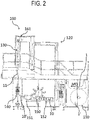
Figure 2 is a side plan view of the packaging machine ofFigure 1 ; -
Figure 3 is a front plan view of the packaging machine ofFigure 1 ; - The
numeral 10 inFigures 1-3 denotes in its entirety a container for pourable food products. Thecontainer 10 is obtained from aweb 1 of wrapping material defined by a laminated multilayer structure comprising a substrate layer, of paper or paperboard, an oxygen barrier layer, of aluminium, and three thermoplastic layers, one of which is interposed between the paper layer and the aluminium layer and adapted to allow the mutual coupling thereof and the other two are adapted to coat the uncovered sides of the paper and aluminium layers, respectively. Thecontainer 10 comprises a parallelepiped shaped body having two opposite ends, a top end and a bottom end. - Each of the ends is provided with a transverse seal obtained by heat sealing two opposite walls of the
web 1 wrapped into the shape of atube 11, thereby forming respective transverse sealing tabs. The two ends are further connected by a longitudinal seal made during the formation of thetube 11 and a defining a further, longitudinal sealing tab. Each end portion protrudes from the parallelepiped shaped body section, with triangular flaps designed to be folded flat against the body by the folding unit, as described in detail below. - The product inside the
container 10 is of a pourable type, for example in the form of powder, granules, leaves or liquid or semiliquid. In the embodiment described below, thecontainer 10 contains fruit juice, hence in liquid form. - The
numeral 100 inFigures 1-3 denotes in its entirety a packaging machine according to this invention for packaging pourable food products in the above mentionedcontainers 10. Thepackaging machine 100 which makescontainers 10 comprises anunwinding unit 110 for unwinding theweb 1 of laminated multilayer material from a roll 1'. Theweb 1 is unwound along a feeding direction MD of theweb 1 along thepackaging machine 100 by means of customary guide roller devices (not illustrated). The feeding direction MD runs from the rear end of themachine 100, where the rolls 1' are, to the front end of it, where thetube 11 is. Thus, the feeding direction may be described as substantially horizontal to the floor even if theweb 1 is fed to the units in succession following a path which is not rectilinear. More specifically, theweb 1 is fed both along horizontal and vertical stretches not only to optimize the space occupied by thepackaging machine 100 but also to keep theweb 1 suitably tensioned along the wrapping path as a whole. - In unwinding the web 1 a
buffer portion 160 is defined by means of a plurality of return rollers (not illustrated). This makes it possible not to interrupt machine operation when a roll is changed. - Similarly, the
buffer 160 allows adapting the speed of feeding theweb 1 to the speed of filling thetube 11 formed, compensating the macro oscillations in the packaging flow. In such case, asecond buffer 161 provided in the proximity of the section where thetube 11 is formed allows adapting the speed of theweb 1 to the speed at which thetube 11 is formed and fed. - At the portion of the
packaging machine 100 occupied by thebuffer 160, there is aunit 170 for feeding atape 12 along the longitudinal edges of theweb 1. Thetape 12 subsequently allows thetube 11 to be sealed longitudinally after it has been formed, downstream of the sterilization unit. - The wrapping path thus extends towards the
sterilization unit 120 which sterilizes theweb 1 being unwound. Thesterilization unit 120 comprises a tank for dipping theweb 1 in a hydrogen peroxide solution, followed by a sterile chamber placed in fluid communication with the tank. - A subsequent portion of the
packaging machine 100 is provided with one or more drying devices which convey theweb 1 to the front portion of thepackaging machine 100 itself. - The
unwinding unit 110, thesterilization unit 120 and thelongitudinal sealing unit 130 are consecutively positioned along the feeding direction MD of theweb 1. More specifically, the consecutive layout does not involve a successive arrangement of the above mentioned units along a rectilinear axis but only the feeding direction of the packaging flow along the units, the packaging flow passing through each of the units in sequence from the rear end to the front end of thepackaging machine 100. - At the front end portion and extending vertically in succession along a sliding direction SD of the
tube 11 are alongitudinal sealing unit 130 for longitudinally sealing the sterilizedweb 1 and adapted to form acontinuous tube 11 of packaging material, and a filling unit adapted to feed the pourable food product into thecontinuous tube 11 formed. - More specifically, the filling unit (not illustrated) is inserted into the
tube 11 being formed before thelongitudinal sealing unit 130 and extends into the same for a stretch such that it operatively follows thesealing unit 130. - Lastly, a forming
unit 140 is located downstream of the final stretch of the filling unit and allows sealing the bottom of thetube 11 formed and cyclically cutting off the sealed wrappers 10' filled with the pourable product. With reference toFigures 1 ,2 and3 , the sliding direction of thetube 11 from thesealing unit 130 to the filling unit and to the formingunit 140 is perpendicular to the floor (that is, to the ground), that is to say, thesealing unit 130, the filling unit and the formingunit 140 are vertically aligned with each other. That means the overall dimensions of themachine 100 can be particularly limited, for example compared to the case where the sliding direction of tube is oblique to the floor. - The forming
unit 140 is defined by two pairs of jaws which cyclically interact with the continuously movingtube 11. These allow heat sealing the bottom portion of thetube 11, so as to prevent loss of the pourable food product while it is being filled, and separating the wrappers filled with the correct quantity of product by sealing the bottom of the movingtube 11 again after the completed sealed wrapper 10' is cut off. The formingunit 140 thus defines wrappers 10' which are filled and sealed and pillow-shaped, that is to say, each wrapper 10' is defined by a front wall and a rear wall, where a longitudinal seal extends along one of these two walls and two opposite transverse seals delimit the upper and lower portions of the walls. - In a further embodiment (not illustrated), the forming unit may be provided with two distinct means operating on the moving tube. More specifically, first heat sealing means, for example two pairs of jaws which cyclically interact with the continuously moving tube, allow sealing the bottom of the tube formed and, cyclically, also sealing a portion upstream of the bottom at a predetermined spacing, thus obtaining a moving tube containing isolated portions of pourable food product. Next, second cutting means, for example a knife and the associated anvil or a pair of cutting rollers, allow separating the isolated portions of the moving tube at the predetermined spacing to obtain respective sealed wrappers filled with the pourable product.
- These wrappers 10' must be further manipulated to complete their forming process so as to obtain the required sealed
package 10. Afolding unit 150 is located downstream of the formingunit 140 and is adapted to complete the forming of the filled and sealed wrappers 10' into sealedcontainers 10 of the desired shape. In the embodiment illustrated, thefolding unit 150 is a conveying star wheel provided with a plurality of housings adapted to hold and move the wrappers 10' along the folding path defined by the star wheel itself. Along the circular conveying path, the star wheel comprises at least one heating device and at least one folding device. The heating device allows heating the portions of the wrapper 10' to be folded in such a way as to bring the thermoplastic layer of the portions concerned to the required temperature. The folding device, on the other hand, allows forming the walls of thecontainer 10 according to the lines of weakness made on theweb 1 of wrapping material and/or folding the heated portions to cause them to adhere to the body of thecontainer 10. - More specifically, the
folding unit 150 is located between the formingunit 140 and the unwindingunit 110. That way, the front end of thepackaging machine 100, at thetube 11, is completely free and thus easy to access for maintenance or other purposes. According to this invention, unlike priorart packaging machines 100, thefolding unit 150 is located within the footprint of thepackaging machine 100 and, in particular in the area between the formingunit 140 and the unwindingunit 110. - The
folding unit 150 is arranged in a direction opposite to the feeding direction MD of theweb 1, forming an open loop packaging flow. - More specifically, the
folding unit 150 moves the filled and sealed wrappers 10' in the direction opposite to the feeding direction of theweb 1. This is done by causing the star wheel to rotate in the direction opposite to the feeding direction of theweb 1. In the embodiment illustrated, this feed motion is accomplished by driving the star wheel clockwise since theweb 1 moves from right to left. - The sealed wrappers 10' are fed by the forming
unit 140 to thefolding unit 150 by suitable feeding means 151 thepackaging machine 100 is equipped with. In the embodiment illustrated, the feeding means 151 comprise an endless conveyor belt trained around a group of pulleys. These move the conveyor belt, and hence the feeding means 151, continuously and in the direction opposite to the feeding direction MD of theweb 1. Thus, the clockwise movement of the conveyor belt allows feeding the filled and sealed wrappers 10' in the direction opposite to the feeding direction MD of theweb 1 as far as the star wheel which forms part of thefolding unit 150. - Downstream of the latter, there are suitable conveyor means 152 adapted to move the sealed
containers 10 from the folding star wheel to the outfeed zone of thepackaging machine 100. More specifically, in the embodiment illustrated, the conveyor means 152 consist of a further conveyor belt which defines a path along which the containers are first extracted from the pocket of the wrapping star wheel when it is at the last position and then continuously fed out of thepackaging machine 100. This conveyor belt moves the sealedcontainers 10 parallel to the feeding direction MD of theweb 1. More specifically, the conveyor belt extracts the sealed and formedcontainers 10 perpendicularly to the feeding direction MD of theweb 1, causing them to follow a U shaped path within the area defined by the footprint of the machine and leading them onto an outfeed path parallel to the feeding direction MD of theweb 1. - Advantageously, the fact that the
containers 10 are fed out of themachine 100 in a direction parallel to the feeding direction MD of the web allows full access to the zone of themachine 100 along which thefolding unit 150, the formingunit 140 and the unwindingunit 110 are located. Action to be taken for maintenance purpose and/or in the event of malfunctioning of the machine 100 (and, more specifically, of thefolding unit 150, formingunit 140 or unwinding unit 110) is therefore made easier because it is easy for the operator to access the parts concerned. - In the embodiment illustrated, the outfeed path runs in the same direction as the feeding direction MD of the
web 1. - In an alternative embodiment (not illustrated), the conveyor means 152 move the sealed
containers 10 perpendicularly to the feeding direction MD of theweb 1. In such case, the conveyor belt extracts the sealed and formedcontainers 10 perpendicularly to the feeding direction MD of theweb 1 without following further paths within the area defined by the footprint of thepackaging machine 100. - To further reduce the machine footprint, the
folding unit 150 is positioned under, and at, thesterilization unit 120. Positioning at thesterilization unit 120 means that thefolding unit 150 is positioned within the area of the machine footprint corresponding or adjacent to thesterilization unit 120, hence comprising also movements limited to the portions adjacent to theselfsame sterilization unit 120. This allows thefolding unit 150 to move the filled and sealed wrappers 10' in a flow which is superposed on and parallel to the feeding direction MD of theweb 1 at thesterilization unit 120. More specifically, thesterilization unit 120 defines part of the packaging flow through movement of theweb 1. Thefolding unit 150 defines part of the packaging flow through movement first of the sealed containers 10' and then of the completedcontainers 10. These two portions of the packaging flow are thus parallel and superposed, defining two branches of the open loop packaging path. - The layout of the units making up the
packaging machine 100 allows provision of free access, that is, of a face that is completely free of other units, at the front of the machine where the longitudinal sealing unit, the filling unit and the forming unit are positioned in vertical succession. This minimizes the time, and hence the cost, needed to operate on these units because it is easy for the operator to access them and thus to take prompt action on any of these units when they require maintenance. - The structure of the packaging flow in the
packaging machine 100 according to the invention also allows considerably reducing the footprint of the unit, thus offering further significant savings in costs connected with the production area occupied. - The packaging of pourable food products in
containers 10 formed from acontinuous web 1 of packaging material is thus defined. - In use, in a first unwinding step, the
web 1 is unwound from a roll 1' along a feeding direction MD of theweb 1 in apackaging machine 100 by means of the unwindingunit 110. Downstream of thebuffer 170, theweb 1 is coupled to thethermoplastic tape 12 along a longitudinal edge. - In a subsequent step, the unwound
web 1 is subjected to sterilization by conveniently diverting theweb 1, together with thetape 12, towards thesterilization unit 120 for sterilizing the unwoundweb 1. Sterilization is accomplished by causing theweb 1 to pass through the tank containing the hydrogen peroxide solution, thus dipping theweb 1 in the solution which sterilizes it completely. The flow of theweb 1 is then diverted into the sterile chamber located immediately downstream of, and in fluid communication with, the peroxide dip tank. - The sterilization fluid must then be removed completely from the
web 1 before it comes into contact with the fruit juice to be packaged in order to prevent it from being contaminated by the peroxide. Air blades inside the sterile chamber direct high pressure air flows at the movingweb 1, thereby drying it and, consequently removing the hydrogen peroxide in excess. - The sterilization step is followed by the step of forming the
continuous tube 11 of packaging material by longitudinally sealing the sterilizedweb 1. The web is wrapped into the shape of atube 11 about the longitudinal axis A of the tube itself, corresponding to the sliding direction SD of thetube 11 after being filled. Concurrently with this wrapping action, a heating device raises the temperature of thetape 12 so as to partly melt it to allow coupling of the two sides of theweb 1 during wrapping along the longitudinal axis. - In a further embodiment (not illustrated) the longitudinal seal may be made on the unwrapped, opposing folded portions of the web so as to make it unnecessary to use the thermoplastic tape.
- The
tube 11 thus formed and in motion is then continuously filled with the pourable product by means of the filling unit thepackaging machine 100 is equipped with. Filling of thetube 11 formed is continuous, like the continuous feed motion of thetube 11 formed. - The filling step is followed by the step of successively forming the filled and sealed wrappers 10' from the
tube 11 along the sliding direction SD of the filledtube 11 itself. The two pairs of jaws forming part of the formingunit 140 cyclically interact with the continuously movingtube 11. These allow heat sealing the bottom portion of thetube 11, so as to prevent loss of the pourable food product while it is being filled. Also during the forming step, the two pairs of jaws cut the filledtube 11 along portions of it transverse to the longitudinal axis A of thetube 11. That way, the wrappers filled with the correct quantity of product are cyclically separated from thetube 11 and, at the same time, the bottom of the movingtube 11 is sealed again at the detached portion of the sealed wrapper 10'. - The conveyor belt of the feeding means 151 then feed the sealed wrappers 10' towards the folding star wheel defining the
folding unit 150 continuously and in the direction opposite to the feeding direction MD of theweb 1. In the next step of folding the sealed wrappers 10', thecontainers 10 are given their required final shape. - The
folding unit 150 allows folding the fins defined by the heat-sealed portions of the wrapping material and folding the wrapper 10' along the lines of weakness made along theweb 1 of packaging material to obtain a container having the shape of a parallelepiped or other required shape. - Based on the position of the
folding unit 150 inside the area defining the footprint of the machine, between the formingunit 140 and the unwindingunit 110, the folding step is carried out while the sealed and filled wrappers 10' are moving in the direction opposite to the feeding direction MD of theweb 1, thus forming an open loop packaging flow. More specifically, the folding step, forming part of the packaging flow, is carried out along a partially circular path defined by the folding star wheel of thefolding unit 150. As the wrappers move along the circular path of the folding star wheel, the heating device allows heating the portions of the wrapper 10' to be folded in such a way as to bring the thermoplastic layer of the portions concerned to the required temperature. The folding device, on the other hand, allows forming the walls of thecontainer 10 according to the lines of weakness made on theweb 1 of wrapping material and/or folding the heated portions to cause them to adhere to the body of thecontainer 10. - Lastly, the
containers 10 are fed out of thepackaging machine 100 by the conveyor means 152. More specifically, in the embodiment illustrated, the conveyor means 152 move the sealedcontainers 10 parallel to the feeding direction MD of theweb 1 by means of a conveyor belt. More specifically, the conveyor belt extracts the sealed and formedcontainers 10 perpendicularly to the feeding direction MD of theweb 1, causing them to follow a U shaped path within the area defined by the footprint of the machine and leading them onto an outfeed path parallel to the feeding direction MD of theweb 1. The outfeed path runs in the same direction as the feeding direction MD of theweb 1. - The
packaging machine 100 may also be provided with accessory units such as, for example, units (not illustrated) for the coupling of caps, straws or pull tabs to the formed containers. These may be positioned along the conveyor belt path inside the area defined by the footprint of the machine. That way, the packaging flow keeps its typical open loop shape, leaving the front of the packaging machine free. - In the further embodiment (not illustrated) where the forming unit is provided with first heat sealing means and second cutting means which are distinct from each other, the steps of the packaging process are the same but with some variations in the forming step.
- More specifically, the filling step is followed by the step of successively forming the filled and sealed wrappers from the tube along the sliding direction SD of the tube itself. The first heat sealing means, consisting for example, of two pairs of jaws, cyclically interact with the continuously moving tube. These allow heat sealing the bottom portion of the tube, so as to prevent loss of the pourable food product while it is being filled. The same pair of jaws also allows sealing a portion upstream of the bottom at a predetermined spacing, thus obtaining a moving tube containing isolated portions of pourable food product.
- Further, in the forming step, the step of cutting the isolated portions of the moving tube at the predetermined spacing to obtain respective sealed wrappers filled with the pourable product is performed by second cutting means, for example consisting of a knife and the associated anvil, That way, the wrappers filled with the correct quantity of product are cyclically separated from the
tube 11 sequentially but independently of the sealing operations carried out during the same forming step. The same results can be obtained in the case where the cutting means consist of a knife and the associated anvil mounted on a pair of cutting rollers between which the tube provided with the isolated portions of pourable food product is made to slide. - The
packaging machine 100 which makesmultilayer containers 10 as described above offers several advantages. - First of all, it allows attaining high hourly outputs, that is to say, high numbers of containers made per unit of time, while guaranteeing a consistently high standard of production quality. The layout of the folding unit and of the feeding and conveyor means, respectively, of the sealed wrappers and of the fully shaped containers, allow the machine to have an appreciably smaller footprint than prior art machines while maintaining the same production capacity.
- Furthermore, the layout of the units making up an open loop packaging flow allows maximizing the use of the machine footprint and minimizing the costs connected with the production area occupied.
- Moreover, the packaging machine described above allows ample room to move around each component, which facilitates both initial assembly and subsequent maintenance (from routine cleaning to substitution) of the components.
Claims (10)
- A packaging machine (100) for packaging pourable food products in containers (10) formed from a continuous web (1) of packaging material, said machine (100) comprises:- at least one unwinding unit (110) for unwinding said web (1) from a roll (1') along a feeding direction (MD) of said web (1) in said machine (100);- a sterilization unit (120) for sterilizing said unwound web (1);- a longitudinal sealing unit (130) for sealing said sterilized web (1) longitudinally to form a continuous tube (11) of packaging material;- a filling unit adapted to feed said pourable food product into said continuous tube (11) formed;- a forming unit (140) adapted to seal said filled tube (11) along portions transverse to the longitudinal axis (A) of said tube (11) and to separate filled and sealed wrappers (10') in succession along the sliding direction (SD) of said filled tube (11);- a folding unit (150) positioned downstream of said forming unit (140) and adapted to complete the forming of said filled and sealed wrappers (10') into said sealed containers (10) according to the desired shape;said machine (100) is characterized in that said folding unit (150) is disposed between said forming unit (140) and said unwinding unit (110), within the footprint of said machine between said forming unit (140) and said unwinding unit (110).
- The packaging machine (100) according to claim 1, wherein said unwinding unit (110), sterilization unit (120) and longitudinal sealing unit (130) are consecutively positioned along said feeding direction (MD) of said web (1), wherein
said filling unit and forming unit (140) are consecutively arranged along said sliding direction (SD), and wherein
said folding unit (150) is arranged in a direction opposite to the feeding direction (MD) of said web (1), forming an open loop packaging flow. - The packaging machine (100) according to claim 1 or 2, wherein said folding unit (150) moves said filled and sealed wrappers (10') in a direction opposite to said feeding direction (MD) of said web (1).
- The packaging machine (100) according to one or more of claims 1 to 3, wherein said folding unit (150) is positioned below and at said sterilization unit (120).
- The packaging machine (100) according to one or more of claims 1 to 4, wherein said folding unit (150) moves said filled and sealed wrappers (10') in a flow superposed on, and parallel to, said feeding direction (MD) of said web (1) at said sterilization unit (120).
- The packaging machine (100) according to one or more of claims 1 to 5, wherein said machine (100) comprises feeding means (151) for feeding said filled and sealed wrappers (10'), said feeding means (151) are interposed between, and operatively connected to, said forming unit (140) and said folding unit (150).
- The packaging machine (100) according to claim 6, wherein said feeding means (151) move said filled and sealed wrappers (10') in a direction opposite to said feeding direction (MD) of said web (1).
- The packaging machine (100) according to one or more of claims 1 to 7, wherein said machine (100) comprises conveyor means (152) located downstream of said folding unit (150) and adapted to move said sealed containers (10) moving out from said machine (100), said conveyor means (152) move said sealed containers (10) along a direction transversal to said feeding direction (MD) of said web (1).
- The packaging machine (100) according to one or more claims of 1 to 7, wherein said machine (100) comprises conveyor means (152) located downstream of said folding unit (150) and adapted to move said sealed containers (10) moving out from said machine (100), said conveyor means (152) move said sealed containers (10) along a direction parallel to said feeding direction (MD) of said web (1).
- A method for packaging pourable food products in containers (10) formed from a continuous web (1) of packaging material, said method comprises the steps of:- unwinding said web (1) from a roll (1') along a feeding direction (MD) of said web (1) in a packaging machine (100); sterilizing said unwound web (1);- forming a continuous tube (11) of packaging material by longitudinally sealing said sterilized web (1);- feeding said pourable food product into said continuous tube (11) formed;- forming filled and sealed wrappers (10') in succession from said tube (11) along the sliding direction (SD) of said filled tube (11) by sealing and cutting said filled tube (11) along portions transverse to the longitudinal axis of said tube (11);- folding said filled and sealed wrappers (10') according to a desired shape after said forming step, thus defining the shape of said filled containers (10); said method is characterized in that said folding step is carried out while said filled and sealed wrappers (10') advance in a direction opposite to the feeding direction (MD) of said web (1), forming an open loop packaging flow.
Applications Claiming Priority (1)
| Application Number | Priority Date | Filing Date | Title |
|---|---|---|---|
| ITBO20150156 | 2015-03-31 |
Publications (2)
| Publication Number | Publication Date |
|---|---|
| EP3075669A1 true EP3075669A1 (en) | 2016-10-05 |
| EP3075669B1 EP3075669B1 (en) | 2017-10-18 |
Family
ID=53385717
Family Applications (1)
| Application Number | Title | Priority Date | Filing Date |
|---|---|---|---|
| EP16162968.8A Active EP3075669B1 (en) | 2015-03-31 | 2016-03-30 | Machine and method for packaging pourable food products in sealed containers formed from a tube of packaging material |
Country Status (1)
| Country | Link |
|---|---|
| EP (1) | EP3075669B1 (en) |
Citations (5)
| Publication number | Priority date | Publication date | Assignee | Title |
|---|---|---|---|---|
| US4034537A (en) * | 1973-07-26 | 1977-07-12 | Altstadter Verpackungs-Vertriebs Gmbh | Method and apparatus for the continuous manufacture of packages for liquids |
| US4510732A (en) * | 1982-03-22 | 1985-04-16 | Tetra Pak International Ab | Machine for the processing of packing containers |
| US4776147A (en) * | 1986-12-17 | 1988-10-11 | International Paper Company | High capacity continuous package seam and tab folding and tacking apparatus |
| WO2010084660A1 (en) * | 2009-01-22 | 2010-07-29 | 四国化工機株式会社 | Container shaping apparatus |
| EP2650223A1 (en) * | 2010-12-06 | 2013-10-16 | Tetra Laval Holdings & Finance SA | Production method for packaging container, and packaging container |
-
2016
- 2016-03-30 EP EP16162968.8A patent/EP3075669B1/en active Active
Patent Citations (5)
| Publication number | Priority date | Publication date | Assignee | Title |
|---|---|---|---|---|
| US4034537A (en) * | 1973-07-26 | 1977-07-12 | Altstadter Verpackungs-Vertriebs Gmbh | Method and apparatus for the continuous manufacture of packages for liquids |
| US4510732A (en) * | 1982-03-22 | 1985-04-16 | Tetra Pak International Ab | Machine for the processing of packing containers |
| US4776147A (en) * | 1986-12-17 | 1988-10-11 | International Paper Company | High capacity continuous package seam and tab folding and tacking apparatus |
| WO2010084660A1 (en) * | 2009-01-22 | 2010-07-29 | 四国化工機株式会社 | Container shaping apparatus |
| EP2650223A1 (en) * | 2010-12-06 | 2013-10-16 | Tetra Laval Holdings & Finance SA | Production method for packaging container, and packaging container |
Also Published As
| Publication number | Publication date |
|---|---|
| EP3075669B1 (en) | 2017-10-18 |
Similar Documents
| Publication | Publication Date | Title |
|---|---|---|
| KR101995089B1 (en) | Folding unit and method for producing pourable food product packages | |
| US9637262B2 (en) | Folding unit for pourable food product packaging machines | |
| CN101316760B (en) | Packaging material sterilizing unit for a pourable food product packaging machine | |
| US10086966B2 (en) | Folding unit for pourable food product packaging machines | |
| EP2960188B1 (en) | Conveying unit for conveying packages and method for conveying packages | |
| KR101854097B1 (en) | Forming assembly and method for forming a plurality of sealed packs for pourable food products starting from a tube of packaging material | |
| CN102470943A (en) | Folding unit for pourable food product packaging machines | |
| KR20170086132A (en) | Forming assembly and method for forming a plurality of sealed packs for pourable food products starting from a tube of packaging material | |
| KR20140135992A (en) | Folding unit for pourable food product packaging machines | |
| JP7787871B2 (en) | Package forming unit, packaging device having package forming unit, and package forming method | |
| US20220177173A1 (en) | Packaging machine for producing sealed packages | |
| JP2025533730A (en) | Folding device and packaging machine having the folding device | |
| EP2789543B1 (en) | A unit for sterilizing a web of packaging material for a machine for packaging pourable food products | |
| JP6685931B2 (en) | Supply unit for supplying sealed packs of liquid food | |
| JP2000355310A (en) | Unit for sterilizing strip packaging materials | |
| CN100556761C (en) | Method and packaging machine for producing sealed packages of pourable food products from pre-cut blanks of sheet packaging material | |
| JP2022520064A (en) | Equipment and methods for producing tubular packaging | |
| JP7115980B2 (en) | Jam detection device, method for detecting defective packages in filling machine, folding unit for producing packages of liquid food in filling machine, and filling machine | |
| IT202200021408A1 (en) | FOLDING APPARATUS AND PACKAGING MACHINE HAVING A FOLDING APPARATUS | |
| EP3075669B1 (en) | Machine and method for packaging pourable food products in sealed containers formed from a tube of packaging material | |
| ITBO20070548A1 (en) | MWTODO FOR TRAINING AND FILLING CONTAINERS. | |
| JP2025511431A (en) | Infeed conveyor for folding device, folding device having infeed conveyor, and packaging machine having folding device | |
| JP2024541816A (en) | Buffer unit for packaging device, packaging device, and method for manufacturing sealed package | |
| JP7418451B2 (en) | Apparatus and method for producing tubular packages | |
| JP3112728U (en) | Interactive buffer for supplying sheet-like packaging material to one or more stations of a packaging machine for packaging fluid food |
Legal Events
| Date | Code | Title | Description |
|---|---|---|---|
| PUAI | Public reference made under article 153(3) epc to a published international application that has entered the european phase |
Free format text: ORIGINAL CODE: 0009012 |
|
| AK | Designated contracting states |
Kind code of ref document: A1 Designated state(s): AL AT BE BG CH CY CZ DE DK EE ES FI FR GB GR HR HU IE IS IT LI LT LU LV MC MK MT NL NO PL PT RO RS SE SI SK SM TR |
|
| AX | Request for extension of the european patent |
Extension state: BA ME |
|
| 17P | Request for examination filed |
Effective date: 20170327 |
|
| RBV | Designated contracting states (corrected) |
Designated state(s): AL AT BE BG CH CY CZ DE DK EE ES FI FR GB GR HR HU IE IS IT LI LT LU LV MC MK MT NL NO PL PT RO RS SE SI SK SM TR |
|
| RIC1 | Information provided on ipc code assigned before grant |
Ipc: B65B 9/207 20120101ALI20170411BHEP Ipc: B65B 65/00 20060101ALI20170411BHEP Ipc: B65B 55/10 20060101AFI20170411BHEP Ipc: B65B 9/12 20060101ALI20170411BHEP Ipc: B65B 61/24 20060101ALI20170411BHEP |
|
| GRAP | Despatch of communication of intention to grant a patent |
Free format text: ORIGINAL CODE: EPIDOSNIGR1 |
|
| INTG | Intention to grant announced |
Effective date: 20170530 |
|
| GRAS | Grant fee paid |
Free format text: ORIGINAL CODE: EPIDOSNIGR3 |
|
| GRAA | (expected) grant |
Free format text: ORIGINAL CODE: 0009210 |
|
| AK | Designated contracting states |
Kind code of ref document: B1 Designated state(s): AL AT BE BG CH CY CZ DE DK EE ES FI FR GB GR HR HU IE IS IT LI LT LU LV MC MK MT NL NO PL PT RO RS SE SI SK SM TR |
|
| REG | Reference to a national code |
Ref country code: GB Ref legal event code: FG4D |
|
| REG | Reference to a national code |
Ref country code: CH Ref legal event code: EP |
|
| REG | Reference to a national code |
Ref country code: AT Ref legal event code: REF Ref document number: 937708 Country of ref document: AT Kind code of ref document: T Effective date: 20171115 Ref country code: IE Ref legal event code: FG4D |
|
| REG | Reference to a national code |
Ref country code: DE Ref legal event code: R096 Ref document number: 602016000580 Country of ref document: DE |
|
| REG | Reference to a national code |
Ref country code: SE Ref legal event code: TRGR |
|
| REG | Reference to a national code |
Ref country code: NL Ref legal event code: MP Effective date: 20171018 |
|
| REG | Reference to a national code |
Ref country code: LT Ref legal event code: MG4D |
|
| PG25 | Lapsed in a contracting state [announced via postgrant information from national office to epo] |
Ref country code: NL Free format text: LAPSE BECAUSE OF FAILURE TO SUBMIT A TRANSLATION OF THE DESCRIPTION OR TO PAY THE FEE WITHIN THE PRESCRIBED TIME-LIMIT Effective date: 20171018 |
|
| PG25 | Lapsed in a contracting state [announced via postgrant information from national office to epo] |
Ref country code: LT Free format text: LAPSE BECAUSE OF FAILURE TO SUBMIT A TRANSLATION OF THE DESCRIPTION OR TO PAY THE FEE WITHIN THE PRESCRIBED TIME-LIMIT Effective date: 20171018 Ref country code: ES Free format text: LAPSE BECAUSE OF FAILURE TO SUBMIT A TRANSLATION OF THE DESCRIPTION OR TO PAY THE FEE WITHIN THE PRESCRIBED TIME-LIMIT Effective date: 20171018 Ref country code: NO Free format text: LAPSE BECAUSE OF FAILURE TO SUBMIT A TRANSLATION OF THE DESCRIPTION OR TO PAY THE FEE WITHIN THE PRESCRIBED TIME-LIMIT Effective date: 20180118 Ref country code: FI Free format text: LAPSE BECAUSE OF FAILURE TO SUBMIT A TRANSLATION OF THE DESCRIPTION OR TO PAY THE FEE WITHIN THE PRESCRIBED TIME-LIMIT Effective date: 20171018 |
|
| PG25 | Lapsed in a contracting state [announced via postgrant information from national office to epo] |
Ref country code: GR Free format text: LAPSE BECAUSE OF FAILURE TO SUBMIT A TRANSLATION OF THE DESCRIPTION OR TO PAY THE FEE WITHIN THE PRESCRIBED TIME-LIMIT Effective date: 20180119 Ref country code: IS Free format text: LAPSE BECAUSE OF FAILURE TO SUBMIT A TRANSLATION OF THE DESCRIPTION OR TO PAY THE FEE WITHIN THE PRESCRIBED TIME-LIMIT Effective date: 20180218 Ref country code: RS Free format text: LAPSE BECAUSE OF FAILURE TO SUBMIT A TRANSLATION OF THE DESCRIPTION OR TO PAY THE FEE WITHIN THE PRESCRIBED TIME-LIMIT Effective date: 20171018 Ref country code: LV Free format text: LAPSE BECAUSE OF FAILURE TO SUBMIT A TRANSLATION OF THE DESCRIPTION OR TO PAY THE FEE WITHIN THE PRESCRIBED TIME-LIMIT Effective date: 20171018 Ref country code: BG Free format text: LAPSE BECAUSE OF FAILURE TO SUBMIT A TRANSLATION OF THE DESCRIPTION OR TO PAY THE FEE WITHIN THE PRESCRIBED TIME-LIMIT Effective date: 20180118 Ref country code: HR Free format text: LAPSE BECAUSE OF FAILURE TO SUBMIT A TRANSLATION OF THE DESCRIPTION OR TO PAY THE FEE WITHIN THE PRESCRIBED TIME-LIMIT Effective date: 20171018 |
|
| REG | Reference to a national code |
Ref country code: DE Ref legal event code: R097 Ref document number: 602016000580 Country of ref document: DE |
|
| PG25 | Lapsed in a contracting state [announced via postgrant information from national office to epo] |
Ref country code: CZ Free format text: LAPSE BECAUSE OF FAILURE TO SUBMIT A TRANSLATION OF THE DESCRIPTION OR TO PAY THE FEE WITHIN THE PRESCRIBED TIME-LIMIT Effective date: 20171018 Ref country code: EE Free format text: LAPSE BECAUSE OF FAILURE TO SUBMIT A TRANSLATION OF THE DESCRIPTION OR TO PAY THE FEE WITHIN THE PRESCRIBED TIME-LIMIT Effective date: 20171018 Ref country code: DK Free format text: LAPSE BECAUSE OF FAILURE TO SUBMIT A TRANSLATION OF THE DESCRIPTION OR TO PAY THE FEE WITHIN THE PRESCRIBED TIME-LIMIT Effective date: 20171018 Ref country code: SK Free format text: LAPSE BECAUSE OF FAILURE TO SUBMIT A TRANSLATION OF THE DESCRIPTION OR TO PAY THE FEE WITHIN THE PRESCRIBED TIME-LIMIT Effective date: 20171018 |
|
| PLBE | No opposition filed within time limit |
Free format text: ORIGINAL CODE: 0009261 |
|
| STAA | Information on the status of an ep patent application or granted ep patent |
Free format text: STATUS: NO OPPOSITION FILED WITHIN TIME LIMIT |
|
| PG25 | Lapsed in a contracting state [announced via postgrant information from national office to epo] |
Ref country code: IT Free format text: LAPSE BECAUSE OF FAILURE TO SUBMIT A TRANSLATION OF THE DESCRIPTION OR TO PAY THE FEE WITHIN THE PRESCRIBED TIME-LIMIT Effective date: 20171018 Ref country code: SM Free format text: LAPSE BECAUSE OF FAILURE TO SUBMIT A TRANSLATION OF THE DESCRIPTION OR TO PAY THE FEE WITHIN THE PRESCRIBED TIME-LIMIT Effective date: 20171018 Ref country code: RO Free format text: LAPSE BECAUSE OF FAILURE TO SUBMIT A TRANSLATION OF THE DESCRIPTION OR TO PAY THE FEE WITHIN THE PRESCRIBED TIME-LIMIT Effective date: 20171018 Ref country code: PL Free format text: LAPSE BECAUSE OF FAILURE TO SUBMIT A TRANSLATION OF THE DESCRIPTION OR TO PAY THE FEE WITHIN THE PRESCRIBED TIME-LIMIT Effective date: 20171018 |
|
| 26N | No opposition filed |
Effective date: 20180719 |
|
| PG25 | Lapsed in a contracting state [announced via postgrant information from national office to epo] |
Ref country code: MC Free format text: LAPSE BECAUSE OF FAILURE TO SUBMIT A TRANSLATION OF THE DESCRIPTION OR TO PAY THE FEE WITHIN THE PRESCRIBED TIME-LIMIT Effective date: 20171018 Ref country code: SI Free format text: LAPSE BECAUSE OF FAILURE TO SUBMIT A TRANSLATION OF THE DESCRIPTION OR TO PAY THE FEE WITHIN THE PRESCRIBED TIME-LIMIT Effective date: 20171018 |
|
| REG | Reference to a national code |
Ref country code: BE Ref legal event code: MM Effective date: 20180331 |
|
| REG | Reference to a national code |
Ref country code: IE Ref legal event code: MM4A |
|
| PG25 | Lapsed in a contracting state [announced via postgrant information from national office to epo] |
Ref country code: LU Free format text: LAPSE BECAUSE OF NON-PAYMENT OF DUE FEES Effective date: 20180330 |
|
| PG25 | Lapsed in a contracting state [announced via postgrant information from national office to epo] |
Ref country code: IE Free format text: LAPSE BECAUSE OF NON-PAYMENT OF DUE FEES Effective date: 20180330 |
|
| PG25 | Lapsed in a contracting state [announced via postgrant information from national office to epo] |
Ref country code: BE Free format text: LAPSE BECAUSE OF NON-PAYMENT OF DUE FEES Effective date: 20180331 |
|
| PG25 | Lapsed in a contracting state [announced via postgrant information from national office to epo] |
Ref country code: FR Free format text: LAPSE BECAUSE OF NON-PAYMENT OF DUE FEES Effective date: 20180331 |
|
| REG | Reference to a national code |
Ref country code: CH Ref legal event code: PL |
|
| PG25 | Lapsed in a contracting state [announced via postgrant information from national office to epo] |
Ref country code: LI Free format text: LAPSE BECAUSE OF NON-PAYMENT OF DUE FEES Effective date: 20190331 Ref country code: CH Free format text: LAPSE BECAUSE OF NON-PAYMENT OF DUE FEES Effective date: 20190331 Ref country code: MT Free format text: LAPSE BECAUSE OF NON-PAYMENT OF DUE FEES Effective date: 20180330 |
|
| PG25 | Lapsed in a contracting state [announced via postgrant information from national office to epo] |
Ref country code: TR Free format text: LAPSE BECAUSE OF FAILURE TO SUBMIT A TRANSLATION OF THE DESCRIPTION OR TO PAY THE FEE WITHIN THE PRESCRIBED TIME-LIMIT Effective date: 20171018 |
|
| REG | Reference to a national code |
Ref country code: AT Ref legal event code: UEP Ref document number: 937708 Country of ref document: AT Kind code of ref document: T Effective date: 20171018 |
|
| PG25 | Lapsed in a contracting state [announced via postgrant information from national office to epo] |
Ref country code: PT Free format text: LAPSE BECAUSE OF FAILURE TO SUBMIT A TRANSLATION OF THE DESCRIPTION OR TO PAY THE FEE WITHIN THE PRESCRIBED TIME-LIMIT Effective date: 20171018 |
|
| PG25 | Lapsed in a contracting state [announced via postgrant information from national office to epo] |
Ref country code: HU Free format text: LAPSE BECAUSE OF FAILURE TO SUBMIT A TRANSLATION OF THE DESCRIPTION OR TO PAY THE FEE WITHIN THE PRESCRIBED TIME-LIMIT; INVALID AB INITIO Effective date: 20160330 Ref country code: MK Free format text: LAPSE BECAUSE OF NON-PAYMENT OF DUE FEES Effective date: 20171018 Ref country code: CY Free format text: LAPSE BECAUSE OF FAILURE TO SUBMIT A TRANSLATION OF THE DESCRIPTION OR TO PAY THE FEE WITHIN THE PRESCRIBED TIME-LIMIT Effective date: 20171018 |
|
| PG25 | Lapsed in a contracting state [announced via postgrant information from national office to epo] |
Ref country code: AL Free format text: LAPSE BECAUSE OF FAILURE TO SUBMIT A TRANSLATION OF THE DESCRIPTION OR TO PAY THE FEE WITHIN THE PRESCRIBED TIME-LIMIT Effective date: 20171018 |
|
| GBPC | Gb: european patent ceased through non-payment of renewal fee |
Effective date: 20200330 |
|
| PG25 | Lapsed in a contracting state [announced via postgrant information from national office to epo] |
Ref country code: GB Free format text: LAPSE BECAUSE OF NON-PAYMENT OF DUE FEES Effective date: 20200330 |
|
| REG | Reference to a national code |
Ref country code: DE Ref legal event code: R081 Ref document number: 602016000580 Country of ref document: DE Owner name: IPI S.R.L., IT Free format text: FORMER OWNER: G.D S.P.A., BOLOGNA, IT Ref country code: DE Ref legal event code: R082 Ref document number: 602016000580 Country of ref document: DE Representative=s name: PRINZ & PARTNER MBB PATENT- UND RECHTSANWAELTE, DE |
|
| REG | Reference to a national code |
Ref country code: AT Ref legal event code: PC Ref document number: 937708 Country of ref document: AT Kind code of ref document: T Owner name: IPI S.R.L., IT Effective date: 20240122 |
|
| PGFP | Annual fee paid to national office [announced via postgrant information from national office to epo] |
Ref country code: SE Payment date: 20260323 Year of fee payment: 11 |
|
| PGFP | Annual fee paid to national office [announced via postgrant information from national office to epo] |
Ref country code: DE Payment date: 20260320 Year of fee payment: 11 |
|
| PGFP | Annual fee paid to national office [announced via postgrant information from national office to epo] |
Ref country code: AT Payment date: 20260318 Year of fee payment: 11 |