EP3075544A1 - Printing apparatus - Google Patents
Printing apparatus Download PDFInfo
- Publication number
- EP3075544A1 EP3075544A1 EP16161532.3A EP16161532A EP3075544A1 EP 3075544 A1 EP3075544 A1 EP 3075544A1 EP 16161532 A EP16161532 A EP 16161532A EP 3075544 A1 EP3075544 A1 EP 3075544A1
- Authority
- EP
- European Patent Office
- Prior art keywords
- ink
- storage unit
- level
- circulation path
- opening
- Prior art date
- Legal status (The legal status is an assumption and is not a legal conclusion. Google has not performed a legal analysis and makes no representation as to the accuracy of the status listed.)
- Granted
Links
Images




Classifications
-
- B—PERFORMING OPERATIONS; TRANSPORTING
- B41—PRINTING; LINING MACHINES; TYPEWRITERS; STAMPS
- B41J—TYPEWRITERS; SELECTIVE PRINTING MECHANISMS, i.e. MECHANISMS PRINTING OTHERWISE THAN FROM A FORME; CORRECTION OF TYPOGRAPHICAL ERRORS
- B41J2/00—Typewriters or selective printing mechanisms characterised by the printing or marking process for which they are designed
- B41J2/005—Typewriters or selective printing mechanisms characterised by the printing or marking process for which they are designed characterised by bringing liquid or particles selectively into contact with a printing material
- B41J2/01—Ink jet
- B41J2/17—Ink jet characterised by ink handling
- B41J2/175—Ink supply systems ; Circuit parts therefor
- B41J2/17566—Ink level or ink residue control
-
- B—PERFORMING OPERATIONS; TRANSPORTING
- B41—PRINTING; LINING MACHINES; TYPEWRITERS; STAMPS
- B41J—TYPEWRITERS; SELECTIVE PRINTING MECHANISMS, i.e. MECHANISMS PRINTING OTHERWISE THAN FROM A FORME; CORRECTION OF TYPOGRAPHICAL ERRORS
- B41J2/00—Typewriters or selective printing mechanisms characterised by the printing or marking process for which they are designed
- B41J2/005—Typewriters or selective printing mechanisms characterised by the printing or marking process for which they are designed characterised by bringing liquid or particles selectively into contact with a printing material
- B41J2/01—Ink jet
- B41J2/17—Ink jet characterised by ink handling
- B41J2/175—Ink supply systems ; Circuit parts therefor
-
- B—PERFORMING OPERATIONS; TRANSPORTING
- B41—PRINTING; LINING MACHINES; TYPEWRITERS; STAMPS
- B41J—TYPEWRITERS; SELECTIVE PRINTING MECHANISMS, i.e. MECHANISMS PRINTING OTHERWISE THAN FROM A FORME; CORRECTION OF TYPOGRAPHICAL ERRORS
- B41J2/00—Typewriters or selective printing mechanisms characterised by the printing or marking process for which they are designed
- B41J2/005—Typewriters or selective printing mechanisms characterised by the printing or marking process for which they are designed characterised by bringing liquid or particles selectively into contact with a printing material
- B41J2/01—Ink jet
- B41J2/17—Ink jet characterised by ink handling
- B41J2/175—Ink supply systems ; Circuit parts therefor
- B41J2/17503—Ink cartridges
-
- B—PERFORMING OPERATIONS; TRANSPORTING
- B41—PRINTING; LINING MACHINES; TYPEWRITERS; STAMPS
- B41J—TYPEWRITERS; SELECTIVE PRINTING MECHANISMS, i.e. MECHANISMS PRINTING OTHERWISE THAN FROM A FORME; CORRECTION OF TYPOGRAPHICAL ERRORS
- B41J2/00—Typewriters or selective printing mechanisms characterised by the printing or marking process for which they are designed
- B41J2/005—Typewriters or selective printing mechanisms characterised by the printing or marking process for which they are designed characterised by bringing liquid or particles selectively into contact with a printing material
- B41J2/01—Ink jet
- B41J2/17—Ink jet characterised by ink handling
- B41J2/175—Ink supply systems ; Circuit parts therefor
- B41J2/17596—Ink pumps, ink valves
-
- B—PERFORMING OPERATIONS; TRANSPORTING
- B41—PRINTING; LINING MACHINES; TYPEWRITERS; STAMPS
- B41J—TYPEWRITERS; SELECTIVE PRINTING MECHANISMS, i.e. MECHANISMS PRINTING OTHERWISE THAN FROM A FORME; CORRECTION OF TYPOGRAPHICAL ERRORS
- B41J2/00—Typewriters or selective printing mechanisms characterised by the printing or marking process for which they are designed
- B41J2/005—Typewriters or selective printing mechanisms characterised by the printing or marking process for which they are designed characterised by bringing liquid or particles selectively into contact with a printing material
- B41J2/01—Ink jet
- B41J2/17—Ink jet characterised by ink handling
- B41J2/18—Ink recirculation systems
-
- B—PERFORMING OPERATIONS; TRANSPORTING
- B41—PRINTING; LINING MACHINES; TYPEWRITERS; STAMPS
- B41J—TYPEWRITERS; SELECTIVE PRINTING MECHANISMS, i.e. MECHANISMS PRINTING OTHERWISE THAN FROM A FORME; CORRECTION OF TYPOGRAPHICAL ERRORS
- B41J29/00—Details of, or accessories for, typewriters or selective printing mechanisms not otherwise provided for
- B41J29/38—Drives, motors, controls or automatic cut-off devices for the entire printing mechanism
Definitions
- the present invention relates to a printing apparatus that includes an ink circulation path having the ink discharge head.
- an ink jet printer which includes a print head that discharges ink, a sub-tank that stores ink, a supply pump that supplies ink to a sub-tank from a main tank containing the ink, and a circulation path having a forward path through which the ink, which is supplied from the sub-tank to the print head, flows, and a backward path through which the ink, which returns to the sub-tank from the print head, flows, has been known (refer to JP-A-2012-183695 ).
- the inventors have found the following problems.
- a height difference between the nozzle surface of the ink discharge head and a level of the ink in the ink storage unit becomes a water head difference which has an influence on a back pressure (hereinafter, referred to as a "head back pressure") of the ink in the ink discharge head.
- a level of the ink stored in the ink storage unit may be positioned within a predetermined height range. Therefore, it is preferable that a liquid sending unit supplies the ink from the ink container to an ink storage unit depending on an ink discharge amount from the ink discharge unit.
- the level of the ink in the ink storage unit becomes lower than a predetermined range, in some cases, such as when the ink is not properly supplied to the ink storage unit due to an abnormality in the liquid sending unit.
- the head back pressure fluctuates.
- An advantage of some aspects of the invention is to provide a printing apparatus in which it is possible to suppress fluctuations of a head back pressure.
- a printing apparatus including: an ink discharge head that discharges ink; an ink storage unit that stores the ink; a liquid sending unit that sends the ink to the ink storage unit from an ink container containing the ink; an ink circulation path having a forward circulation path through which the ink, which is supplied to the ink discharge head from the ink storage unit, flows, and a backward circulation path through which the ink, which returns to the ink storage unit from the ink discharge head, flows; and a receptacle that has an opening opened upward and is provided inside the ink storage unit, in which an end portion of the backward circulation path on the ink storage unit side is positioned below the opening inside the receptacle and an end portion of the forward circulation path on the ink storage unit side is positioned below the receptacle inside the ink storage unit.
- the end portion of the backward circulation path on the ink storage unit side is positioned below the opening inside the receptacle and the end portion of the forward circulation path on the ink storage unit side is positioned below the receptacle. Therefore, even in a case where the level of the ink in the ink storage unit becomes lower than the height position of the opening, the ink inside the receptacle is not reduced but the level of the ink in the receptacle is maintained to be equal to the height position of the opening.
- a height difference between the nozzle surface of the ink discharge head and the opening of the receptacle is hereby a water head difference which has an influence on the head back pressure. Accordingly, in a case where the level of the ink in the ink storage unit becomes lower than a predetermined height range due to an abnormality in the liquid sending unit, the head back pressure does not fluctuate because the water head difference which has an influence on the head back pressure is maintained to be a constant value (the height difference between the nozzle surface of the ink discharge head and the opening of the receptacle). Hence, in the printing apparatus, it is possible to control the fluctuation of the head back pressure.
- the apparatus further includes a control unit that controls the liquid sending unit such that the level of the ink in the ink storage unit is positioned in a range equal to or higher than the first level which is a position equal to the height position of the opening and equal to or lower than the second level which is a position higher than the height position of the opening by a predetermined length.
- the level of the ink in the ink storage unit is positioned between the first level which is a position equal to the height position of the opening and the second level which is a position higher than the height position of the opening by a predetermined length.
- the water head difference which has an influence on the head back pressure becomes the smallest value; however, even in this case, the water head difference is a value smaller than the height difference between the nozzle surface of the ink discharge head and the opening of the receptacle, by a predetermined length.
- the value means the water head difference which has an influence on the head back pressure and changes only by the predetermined length at most. Accordingly, according to the configuration, it is possible to reduce a difference between the head back pressure obtained in a case where the liquid sending unit normally operates and the head back pressure obtained in a case where the liquid sending unit has an abnormality.
- control unit controls the liquid sending unit such that the level of the ink in the ink storage unit is equal to the first level.
- the apparatus further includes: a control unit that controls the liquid sending unit such that the level of the ink in the ink storage unit becomes lower than the first level which is a position equal to the height position of the opening; and a check valve that is provided in the backward circulation path and blocks the ink from reversely flowing to the ink discharge head in the backward circulation path.
- the control is performed such that the level of the ink in the ink storage unit becomes lower than the first level. Therefore, in the case where the liquid sending unit normally operates, the height difference between the nozzle surface of the ink discharge head and the opening of the receptacle becomes the water head difference which has an influence on the head back pressure. Accordingly, it is possible to eliminate the difference between the head back pressure obtained in the case where the liquid sending unit normally operates and the head back pressure obtained in the case where the liquid sending unit has an abnormality.
- the level of the ink in the ink storage unit becomes lower than the level of the ink in the receptacle and circulation of the ink in the ink circulation path is stopped, the reverse flowing of the ink in the ink circulation path is suppressed because the check valve is provided in the backward circulation path.
- the apparatus further includes a supply flow path through which the ink, which is supplied to the ink storage unit from the ink container, flows, and the control unit controls the liquid sending unit such that the level of the ink in the ink storage unit is positioned above the height position of the end portion of the supply flow path on the ink storage unit side.
- the ink flows from the supply flow path to the ink storage unit at a position below the level of the ink in the ink storage unit. Therefore, the generation of the bubbles in the ink in the ink storage unit is suppressed when the ink flows into the ink storage unit.
- a height difference between the nozzle surface of the ink discharge head and the opening of the receptacle is a height difference causing a back pressure, with which no air infiltrates into the inside of the ink discharge head from a nozzle and no ink leaks from the nozzle of the ink discharge head, to be applied to the ink in the ink discharge head.
- the apparatus further includes an attachment member through which the receptacle is attached to the end portion of the backward circulation path on the ink storage unit side.
- the receptacle is attached to the end portion of the backward circulation path on the ink storage unit side through the attachment member.
- a printing apparatus including: an ink discharge head that discharges ink; an ink storage unit that stores the ink; a liquid sending unit that sends the ink to the ink storage unit from an ink container containing the ink; an ink circulation path having a forward circulation path through which the ink, which is supplied to the ink discharge head from the ink storage unit, flows, and a backward circulation path through which the ink, which returns to the ink storage unit from the ink discharge head, flows; and a receptacle that has a first opening and a second opening positioned below the first opening, and that is provided in the ink storage unit, in which an end portion of the backward circulation path on the ink storage unit side is connected to the second opening and an end portion of the forward circulation path on the ink storage unit side is positioned below the receptacle inside the ink storage unit.
- the end portion of the backward circulation path on the ink storage unit side is connected to the second opening which is a position below the first opening and the end portion of the forward circulation path on the ink storage unit side is positioned below the receptacle. Therefore, even in a case where the level of the ink in the ink storage unit is lower than the height position of the first opening, the ink inside the receptacle is not reduced but the level of the ink in the receptacle is maintained to be equal to the height position of the first opening.
- a height difference between the nozzle surface of the ink discharge head and the first opening of the receptacle is hereby a water head difference which has an influence on the head back pressure. Accordingly, in a case where the level of the ink in the ink storage unit becomes lower than a predetermined height range due to an abnormality in the liquid sending unit, the head back pressure does not fluctuate because the water head difference which has an influence on the head back pressure is maintained to be a constant value (the height difference between the nozzle surface of the ink discharge head and the first opening of the receptacle). Hence, in the printing apparatus, it is possible to control the fluctuation of the head back pressure.
- the second opening is provided on the side surface of the receptacle, a joint communicating with the second opening is provided on the side surface of the receptacle, and the end portion of the backward circulation path on the ink storage unit side is fitted to the joint.
- the printing apparatus 1 performs printing to a set printing medium 100 by discharging ultraviolet curing ink (hereinafter, referred to as "UV ink").
- the printing medium 100 is strip-shaped continuous paper. Further, there is no particular limitation on a material of the printing medium 100 and various media such as a paper medium or a film medium are used.
- the printing apparatus 1 includes a feeding unit 2, an ink discharge section 3, and an irradiation unit 4.
- the printing apparatus 1 includes an ink supply unit 5 (refer to Fig. 2 ) which supplies the UV ink to the ink discharge section 3.
- the feeding unit 2 feeds the printing medium 100 in a roll-to-roll method.
- the feeding unit 2 includes a supply reel 6, a winding reel 7, a rotating drum 8, and a plurality of rollers 9.
- the printing medium 100 supplied from the supply reel 6 is wound around the winding reel 7 via the rotating drum 8 and the plurality of rollers 9.
- the rotating drum 8 is a cylindrical drum which is rotatably supported by a support mechanism (not illustrated). When the printing medium 100 is fed along a circumferential surface of the rotating drum 8, the rotating drum 8 is driven to rotate due to frictional force between the circumferential surface and the printing medium 100.
- the rotating drum 8 functions as a platen with respect to the ink discharge section 3.
- the ink discharge section 3 includes a plurality of head units 11.
- the plurality of head units 11 are arranged along the circumferential surface of the rotating drum 8.
- the plurality of head units 11 are in one-to-one correspondence to a plurality of types (for example, four colors of CMYK) of UV ink.
- Each of the head units 11 includes a plurality of ink discharge heads 12 (refer to Fig. 2 ) which discharge UV ink in an ink jet method.
- the head unit 11 discharges UV ink to the printing medium 100 supported on the circumferential surface of the rotating drum 8. A color image is hereby formed on the printing medium 100.
- the irradiation unit 4 includes a plurality of pre-curing irradiators 13 and a main-curing irradiator 14.
- the plurality of pre-curing irradiators 13 are arranged along the circumferential surface of the rotating drum 8 to be alternately positioned with the plurality of head units 11.
- the pre-curing irradiator 13 is provided on the downstream side on a feeding route of the printing medium 100 with respect to the corresponding head unit 11.
- the pre-curing irradiator 13 irradiates, with ultraviolet, the printing medium 100 to which the UV ink is discharged.
- the UV ink is hereby temporarily or partially cured immediately after landing on the printing medium 100, and thus spreading of a dot or color mixing is suppressed.
- the main-curing irradiator 14 is provided further on the downstream side from the pre-curing irradiator 13 provided on the most downstream side on the feeding route.
- the main-curing irradiator 14 irradiates the printing medium 100, on which the discharge of the UV ink and the pre-curing are performed, with a cumulative intensity of ultraviolet light which is greater than that of the pre-curing irradiators 13.
- the UV ink landing on the printing medium 100 is hereby completely cured and is fixed on the printing medium 100.
- a light emitting diode (LED) lamp, a high-pressure mercury lamp, or the like, which performs irradiation with the ultraviolet can be used.
- the ink supply unit 5 will be described with reference to Fig. 2 .
- the ink supply unit 5 includes an ink cartridge 21, a supply flow path 22, a supply on-off valve 23, a supply pump 24, a sub-tank 25, a level sensor 26, a pressure regulating unit 27, an ink circulation path 28, a forward-path filter 30, a heating unit 31, a de-airing unit 32, a check valve 33, a receptacle 53, and a control unit 60.
- the UV ink is contained in the ink cartridge 21.
- the ink cartridge 21 is mounted on a holder 34.
- the upstream-side end of the supply flow path 22 is inserted into the ink cartridge 21 mounted on the holder 34 and the downstream-side end (hereinafter, referred to as a "supply-path downstream-side end 22c") of the supply flow path 22 is inserted into the sub-tank 25.
- the supply-path downstream-side end 22c is positioned below a first level L1 to be described below.
- the supply on-off valve 23 and the supply pump 24 are provided in the supply flow path 22 in this order from the upstream side.
- the supply on-off valve 23 opens and closes the supply flow path 22.
- a solenoid-controlled valve can be used as the supply on-off valve 23 as the supply on-off valve 23 as the supply on-off valve 23, a solenoid-controlled valve can be used.
- the supply pump 24 sends the UV ink contained in the ink cartridge 21 to the sub-tank 25 through the supply flow path 22.
- the supply pump 24 is controlled by the control unit 60.
- the sub-tank 25 temporarily stores the UV ink sent from the ink cartridge 21.
- the sub-tank 25 is open-ended.
- the level sensor 26 detects whether or not the level (hereinafter, referred to as a "tank level 25a") of the UV ink in the sub-tank 25 is equal to or higher than a first level L1 and detects whether or not the level is higher than the first level L1 and is equal to or higher than a second level L2.
- the first level L1 is a level at which back pressure of the UV ink inside the ink discharge head 12 becomes optimal.
- a head back pressure with which no bubbles infiltrate into the inside of the ink discharge head 12 from the nozzle and no UV ink leak from the nozzle of the ink discharge head 12, is applied to the UV ink inside the ink discharge head 12.
- the first level L1 is set to a height position of an opening 76 of the receptacle 53 to be described below.
- the second level L2 is positioned at a distance of 5 mm above the first level L1.
- the control unit 60 When the level sensor 26 detects that the tank level 25a is lower than the first level L1, the control unit 60 operates the supply pump 24. The sub-tank 25 is hereby refilled with the UV ink from the ink cartridge 21. When the level sensor 26 detects that the tank level 25a is equal to or higher than the second level L2, the control unit 60 stops the supply pump 24. The supply of the UV ink to the sub-tank 25 from the ink cartridge 21 is hereby stopped. In this manner, the control unit 60 controls the supply pump 24 such that the tank level 25a is positioned between the first level L1 and the second level L2.
- the tank level 25a is controlled to be positioned between the height position of the opening 76 of the receptacle 53 and a position at a distance of 5 mm above the height position of the opening 76.
- the tank level 25a is controlled to be positioned above the height position of the supply-path downstream-side end 22c.
- the height position of the opening 76 of the receptacle 53 is referred to as a position at the lower end of the height position in a portion which defines the opening 76 on the wall surface of the receptacle 53.
- the pressure regulating unit 27 supplies air into the sub-tank 25 or emits air in the sub-tank 25 through an air flow path 35, and thereby the inside of the sub-tank 25 is pressurized or depressurized.
- the pressure regulating unit 27 pressurizes the sub-tank 25 during initial filling of the ink circulation path 28 with the UV ink, cleaning of the ink discharge head 12, or the like.
- the ink circulation path 28 is a flow path of the UV ink which returns from the sub-tank 25 through the ink discharge head 12 to the sub-tank 25.
- the ink circulation path 28 includes a forward circulation path 36 and a backward circulation path 37.
- the UV ink which is supplied to the ink discharge head 12 from the sub-tank 25, flows through the forward circulation path 36.
- the forward circulation path 36 includes a forward-path-side inter-path 36a, and a plurality of forward-path-side diverged paths 36b which diverge from the forward-path-side inter-path 36a.
- the upstream-side end hereinafter, referred to as a "forward-path upstream-side end 36c" of the forward-path-side inter-path 36a is inserted into the sub-tank 25.
- the forward-path-side inter-path 36a extends to the vicinity of the bottom of the sub-tank 25 such that substantially the entire amount of the UV ink in the sub-tank 25 can be removed as liquid waste through the forward-path-side inter-path 36a. That is, the forward-path upstream-side end 36c is positioned below the supply-path downstream-side end 22c or a backward-path downstream-side end 37c. On the forward-path-side inter-path 36a, a circulation pump 29, the forward-path filter 30, the heating unit 31, and the de-airing unit 32, are provided in this order from the upstream side. Further, one forward-path-side diverged path 36b is provided with respect to each ink discharge head 12. The downstream-side end of the forward-path-side diverged path 36b is connected to the ink discharge head 12.
- the UV ink which returns to the sub-tank 25 from the ink discharge head 12, flows through the backward circulation path 37.
- the backward circulation path 37 includes a plurality of backward-path-side diverged paths 37b and a backward-path-side inter-path 37a to which the plurality of backward-path-side diverged paths 37b joins on the downstream side.
- a backward-path-side diverged path 37b is provided with respect to each ink discharge head 12.
- the upstream-side end of the backward-path-side diverged path 37b is connected to the ink discharge head 12.
- the downstream-side end (backward-path downstream-side end 37c) of the backward-path-side inter-path 37a is inserted into the sub-tank 25.
- the backward-path downstream-side end 37c is positioned below the first level L1.
- the receptacle 53 is attached to the backward-path downstream-side end 37c.
- the check valve 33 is provided in the backward-path-side inter-path 37a.
- the circulation pump 29 sends the UV ink stored in the sub-tank 25 toward the ink discharge head 12 side. Further, as the circulation pump 29, a gear pump can be appropriately used since the gear pump can suppress pulsation and has temporally small flow fluctuation.
- the forward-path filter 30 filters the UV ink flowing through the forward circulation path 36, and thereby removes foreign matter in the UV ink.
- Foreign matter includes, for example, dust mixed when the upstream-side end of the supply flow path 22 is inserted into the ink cartridge 21, a polymer of the UV ink due to frictional heat generated in the circulation pump 29 which is a gear pump, or the like.
- a head filter 38 that filters the UV ink is also provided on the inflow side of the ink discharge head 12; however, the forward-path filter 30 is provided in the forward circulation path 36, and thereby it is possible to sustain the head filter 38 which is difficult to replace.
- the heating unit 31 heats the UV ink flowing through the ink circulation path 28 to a predetermined temperature (for example, 35°C to 40°C).
- the predetermined temperature is a temperature at which the UV ink which is supplied to the ink discharge head 12 has a viscosity suitable for discharge from the ink discharge head 12.
- the UV ink having a temperature lower than the predetermined temperature is heated to the predetermined temperature by the heating unit 31, and then the printing apparatus 1 starts a printing operation.
- the heating unit 31 includes a hot-water tank 41 having a heater and a thermometer, a hot-water circulating path 42, a hot-water pump 43, and a heat exchanger 44.
- the hot-water tank 41 stores hot water having a temperature adjusted within a predetermined temperature range.
- the hot-water circulating path 42 is a flow path through which hot water returns to the hot-water tank 41 through the heat exchanger 44 from the hot-water tank 41.
- the hot-water pump 43 circulates the hot water in the hot-water circulating path 42.
- the heat exchanger 44 performs heat exchange between the hot water flowing through the hot-water circulating path 42 and the UV ink flowing through the ink circulation path 28.
- the de-airing unit 32 expels air form the UV ink flowing through the ink circulation path 28.
- the UV ink containing bubbles is hereby prevented from being supplied to the ink discharge head 12.
- the de-airing unit 32 includes a de-airing module 45 and a negative pressure pump 46.
- the de-airing module 45 includes a plurality of hollow fiber membranes.
- the negative pressure pump 46 depressurizes the outer side of the hollow fiber membrane. Air is hereby expelled from the UV ink flowing in the hollow fiber membrane.
- the check valve 33 allows the UV ink to flow to the sub-tank 25 side in the backward circulation path 37 and blocks the UV ink from reversely flowing to the ink discharge head 12 side.
- the foreign matter which is contained in the UV ink reversely flowing through the backward circulation path 37 is prevented from entering the ink discharge head 12 by the check valve 33.
- the UV ink reversely flows to the ink discharge head 12 side in the backward circulation path 37.
- the receptacle 53 and the attachment member 73 will be described with reference to Figs. 3A to 3C .
- the receptacle 53 is attached to the backward-path downstream-side end 37c through an attachment member 73.
- the attachment member 73 includes a fitting portion 74 and three engagement portions 75.
- the fitting portion 74 is formed to have an annular shape.
- the fitting portion 74 fits in a circular groove formed around the end of the backward-path downstream-side end 37c.
- the three engagement portions 75 are provided with respect to the fitting portion 74 substantially at an equal interval in a circumferential direction and protrude in the radial direction of the fitting portion 74.
- the distal end of the engagement portion 75 engages with a notch 78 to be described below.
- the receptacle 53 is formed to have substantially a cylindrical shape with a bottom. That is, the receptacle 53 has an opening 76 opened upward.
- the three notches 78 are provided substantially at an equal interval on the upper end portion of the receptacle 53.
- the distal end of the engagement portion 75 engages with the notch 78.
- the backward-path downstream-side end 37c is inserted into the inside of the receptacle 53 through the opening 76 of the receptacle 53 but the forward-path upstream-side end 36c is not inserted into the inside of the receptacle.
- the receptacle 53 is provided such that the height position of the opening 76 is the same level as the first level L1 (refer to Fig. 2 ).
- Figs. 4A and 4B illustrate a peripheral configuration of the sub-tank 25 in a case where the receptacle 53 is not provided inside the sub-tank 25, which is different from the printing apparatus 1 of the present embodiment.
- a height difference between the nozzle surface 12a of the ink discharge head 12 and the tank level 25a becomes a water head difference ⁇ H which has an influence on a head back pressure.
- the tank level 25a is maintained between the first level L1 and the second level L2 (refer to Fig. 4A ).
- the UV ink is not properly supplied to the sub-tank 25 due to an abnormality such as deterioration or malfunction in the supply pump 24, and thus the tank level 25a becomes lower than the first level L1 in some cases (refer to Fig. 4B ).
- the height difference between the nozzle surface 12a of the ink discharge head 12 and the tank level 25a increases and the water head difference ⁇ H has a relatively large negative pressure which has an influence on the head back pressure.
- air infiltrates into the inside of the ink discharge head 12 from the nozzle.
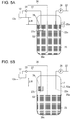
- Figs. 5A and 5B illustrate a peripheral configuration of the sub-tank 25, which includes a receptacle 53, of the printing apparatus 1 of the present embodiment.
- the backward-path downstream-side end 37c is positioned below the opening 76 inside the receptacle 53 and the forward-path upstream-side end 36c is positioned below the receptacle 53 inside the sub-tank 25.
- the UV ink in the receptacle 53 is not reduced but the level (hereinafter, referred to as a receptacle level 53a) of the UV ink in the receptacle 53 maintains the same level as the height position of the opening 76, that is, the first level L1 (refer to Fig. 5B ).
- the tank level 25a becomes lower than the height position of the opening 76
- the height difference between the nozzle surface 12a of the ink discharge head 12 and the opening 76 of the receptacle 53 hereby becomes the water head difference ⁇ H which has an influence on the head back pressure.
- the control unit 60 stops the printing apparatus 1 after a predetermined continuous duration of the state in which the tank level 25a becomes lower than the first level L1.
- the tank level 25a is controlled to be between the first level L1 and the second level L2, that is, between the height position of the opening 76 and the position which is 5 mm above the height position (refer to Fig. 5A ).
- the water head difference ⁇ H which has an influence on the head back pressure becomes the lowest; however, even in this case, the water head difference is a value which is smaller only by 5 mm than the height difference between the nozzle surface 12a and the opening 76.
- the printing apparatus 1 of the present embodiment it is possible to control the fluctuation of the head back pressure.
- the tank level 25a is controlled to be positioned below the height position of the supply-path downstream-side end 22c.
- the UV ink hereby flows to the sub-tank 25 from the supply flow path 22 at a position below the level of the UV ink in the sub-tank 25. Therefore, when the UV ink flows into the sub-tank 25, generation of air in the UV ink in the sub-tank 25 is suppressed.
- the height difference between the nozzle surface 12a and the opening 76 (first level L1) is the height difference causing the head back pressure, with which no air infiltrates into the inside of the ink discharge head 12 from the nozzle and no UV ink leaks from the nozzle of the ink discharge head 12, to be applied to the UV ink in the ink discharge head 12.
- Infiltration of the air from the nozzle into the inside of the ink discharge head 12 is hereby suppressed and leakage of the UV ink from the nozzle of the ink discharge head 12 is suppressed.
- sub-tank 25 is an example of an "ink storage unit”.
- the ink cartridge 21 is an example of an "ink container”.
- the supply pump 24 is an example of a "liquid sending unit”.
- the control unit 60 may control the supply pump 24 such that the tank level 25a is positioned not only between the first level L1 and the second level L2, but also between the height position of the opening 76 and a position in a range of equal to or less than 5 mm above the height position of the opening 76.
- the control unit 60 may control the supply pump 24 such that the tank level 25a is maintained at a predetermined position in a range of equal to or less than 5 mm above the height position of the opening 76. It is possible to hereby have no fluctuation range in the head back pressure while the supply pump 24 normally operates.
- the control unit 60 may control the supply pump 24 such that the tank level 25a is maintained at the height position of the opening 76.
- the second level L2 is not limited to a position which is 5 mm above the first level L1.
- the second level L2 may be appropriately set such that the head back pressure is within a permissible range in which no air is infiltrated into the inside of the ink discharge head from the nozzle and no ink leaks from the nozzle of the ink discharge head.
- the check valve 33 is provided in the backward circulation path 37; however, it is possible to omit the check valve 33.
- the first level L1 is set to a height equal to or higher than the height position of the opening 76 of the receptacle 53 such that the UV ink does not reversely flow in the ink circulation path 28 in a case where the circulation of the UV ink is stopped in the ink circulation path 28.
- the control unit 60 may control the supply pump 24 such that the tank level 25a becomes lower than the first level L1 which is the height position of the opening 76.
- the height difference between the nozzle surface 12a and the opening 76 becomes the water head difference ⁇ H which has an influence on the head back pressure. Accordingly, it is possible to hereby eliminate the difference between the head back pressure obtained in a case where the supply pump 24 normally operate and the head back pressure obtained in a case where the supply pump 24 has an abnormality.
- the tank level 25a is less than the receptacle level 53a; however, even in a case where the circulation of UV ink is stopped in the ink circulation path 28 when an operation of the printing apparatus 1 is stopped or the like, the check valve 33 is provided in the backward circulation path 37. Therefore, the UV ink is prevented from reversely flowing in the ink circulation path 28. Further, as described in the embodiment above, the check valve 33 may be provided in the backward-path-side inter-path 37a or may be provided for each backward-path-side diverged path 37b. Further, the control unit 60 stops the printing apparatus 1 after a predetermined continuous duration of the state in which the tank level 25a becomes lower than the third level L3.
- the fourth level L4 may be set as a determination criterion. In this manner, it is possible to prevent the tank level 25a from becoming lower than the height position of the forward-path upstream-side end 36c and to prevent air from entering from the forward-path upstream-side end 36c, due to printing continuation in the state in which the UV ink is not properly supplied to the sub-tank 25.
- the third level L3 is a predetermined position below the first level L1 and below the supply-path downstream-side end 22c.
- the fourth level L4 is a predetermined position below the supply-path downstream-side end 22c and below the forward-path upstream-side end 36c.
- the shape of the receptacle 53 is not particularly limited and, for example, may be substantially an inverted cone.
- the receptacle 53 may not have the opening 76 opened upward.
- the shape of the receptacle 53 can be a shape illustrated in Figs. 7A and 7B .
- the receptacle 53 is formed to be substantially cylindrical with the bottom and the ceiling and includes a first opening 81 provided on the side surface of the cylinder and a second opening 82 provided on the side surface of the cylinder below the first opening 81.
- the backward-path downstream-side end 37c is connected to the second opening 82 and the receptacle 53 is supported by a ring-shaped receptacle support 83 provided on the wall surface of the sub-tank 25 such that the lower end of the first opening is positioned at the first level L1.
- connection between the backward-path downstream-side end 37c and the second opening 82 may be performed by fitting and connecting the backward-path downstream-side end 37c and a joint 84 provided on the side surface of the cylinder. This case is also included in a case where "the end portion of the backward circulation path on the ink storage unit side is positioned below the opening inside the receptacle".
- the ink used in the printing apparatus 1 is not limited to the UV ink and, for example, water-based ink, oil-based ink, solvent ink or sublimation ink may be used.
Landscapes
- Ink Jet (AREA)
Abstract
Description
- The present invention relates to a printing apparatus that includes an ink circulation path having the ink discharge head.
- Recently, an ink jet printer, which includes a print head that discharges ink, a sub-tank that stores ink, a supply pump that supplies ink to a sub-tank from a main tank containing the ink, and a circulation path having a forward path through which the ink, which is supplied from the sub-tank to the print head, flows, and a backward path through which the ink, which returns to the sub-tank from the print head, flows, has been known (refer to
JP-A-2012-183695 - The inventors have found the following problems.
- In the printing apparatus such as an ink jet printer in the related art, a height difference between the nozzle surface of the ink discharge head and a level of the ink in the ink storage unit becomes a water head difference which has an influence on a back pressure (hereinafter, referred to as a "head back pressure") of the ink in the ink discharge head. In order to control fluctuation of the head back pressure, a level of the ink stored in the ink storage unit may be positioned within a predetermined height range. Therefore, it is preferable that a liquid sending unit supplies the ink from the ink container to an ink storage unit depending on an ink discharge amount from the ink discharge unit. However, the level of the ink in the ink storage unit becomes lower than a predetermined range, in some cases, such as when the ink is not properly supplied to the ink storage unit due to an abnormality in the liquid sending unit. In this case, since the height difference between the nozzle surface of the ink discharge head and the level of the ink in the ink storage unit, that is, the water head difference which has an influence on the head back pressure becomes greater, the head back pressure fluctuates.
- An advantage of some aspects of the invention is to provide a printing apparatus in which it is possible to suppress fluctuations of a head back pressure.
- According to an aspect of the invention, there is provided a printing apparatus including: an ink discharge head that discharges ink; an ink storage unit that stores the ink; a liquid sending unit that sends the ink to the ink storage unit from an ink container containing the ink; an ink circulation path having a forward circulation path through which the ink, which is supplied to the ink discharge head from the ink storage unit, flows, and a backward circulation path through which the ink, which returns to the ink storage unit from the ink discharge head, flows; and a receptacle that has an opening opened upward and is provided inside the ink storage unit, in which an end portion of the backward circulation path on the ink storage unit side is positioned below the opening inside the receptacle and an end portion of the forward circulation path on the ink storage unit side is positioned below the receptacle inside the ink storage unit.
- In this case, the end portion of the backward circulation path on the ink storage unit side is positioned below the opening inside the receptacle and the end portion of the forward circulation path on the ink storage unit side is positioned below the receptacle. Therefore, even in a case where the level of the ink in the ink storage unit becomes lower than the height position of the opening, the ink inside the receptacle is not reduced but the level of the ink in the receptacle is maintained to be equal to the height position of the opening. In a case where the level of the ink in the ink storage unit becomes lower than the height position of the opening, a height difference between the nozzle surface of the ink discharge head and the opening of the receptacle is hereby a water head difference which has an influence on the head back pressure. Accordingly, in a case where the level of the ink in the ink storage unit becomes lower than a predetermined height range due to an abnormality in the liquid sending unit, the head back pressure does not fluctuate because the water head difference which has an influence on the head back pressure is maintained to be a constant value (the height difference between the nozzle surface of the ink discharge head and the opening of the receptacle). Hence, in the printing apparatus, it is possible to control the fluctuation of the head back pressure.
- In the printing apparatus, it is preferable that the apparatus further includes a control unit that controls the liquid sending unit such that the level of the ink in the ink storage unit is positioned in a range equal to or higher than the first level which is a position equal to the height position of the opening and equal to or lower than the second level which is a position higher than the height position of the opening by a predetermined length.
- In this case, the level of the ink in the ink storage unit is positioned between the first level which is a position equal to the height position of the opening and the second level which is a position higher than the height position of the opening by a predetermined length. Here, in a case where the level of the ink in the ink storage unit is positioned at the second level, the water head difference which has an influence on the head back pressure becomes the smallest value; however, even in this case, the water head difference is a value smaller than the height difference between the nozzle surface of the ink discharge head and the opening of the receptacle, by a predetermined length. As described above, in a case where the level is lower than a predetermined height range of the ink in the ink storage unit due to the abnormality in the liquid sending unit, the value means the water head difference which has an influence on the head back pressure and changes only by the predetermined length at most. Accordingly, according to the configuration, it is possible to reduce a difference between the head back pressure obtained in a case where the liquid sending unit normally operates and the head back pressure obtained in a case where the liquid sending unit has an abnormality.
- In the printing apparatus, it is preferable that the control unit controls the liquid sending unit such that the level of the ink in the ink storage unit is equal to the first level.
- In this case, it is possible to eliminate the difference between the head back pressure obtained in the case where the liquid sending unit normally operates and the head back pressure obtained in the case where the liquid sending unit has an abnormality.
- In the printing apparatus, it is preferable that the apparatus further includes: a control unit that controls the liquid sending unit such that the level of the ink in the ink storage unit becomes lower than the first level which is a position equal to the height position of the opening; and a check valve that is provided in the backward circulation path and blocks the ink from reversely flowing to the ink discharge head in the backward circulation path.
- In this case, the control is performed such that the level of the ink in the ink storage unit becomes lower than the first level. Therefore, in the case where the liquid sending unit normally operates, the height difference between the nozzle surface of the ink discharge head and the opening of the receptacle becomes the water head difference which has an influence on the head back pressure. Accordingly, it is possible to eliminate the difference between the head back pressure obtained in the case where the liquid sending unit normally operates and the head back pressure obtained in the case where the liquid sending unit has an abnormality.
- Further, in a case where the level of the ink in the ink storage unit becomes lower than the level of the ink in the receptacle and circulation of the ink in the ink circulation path is stopped, the reverse flowing of the ink in the ink circulation path is suppressed because the check valve is provided in the backward circulation path.
- In the printing apparatus, it is preferable that the apparatus further includes a supply flow path through which the ink, which is supplied to the ink storage unit from the ink container, flows, and the control unit controls the liquid sending unit such that the level of the ink in the ink storage unit is positioned above the height position of the end portion of the supply flow path on the ink storage unit side.
- In this case, the ink flows from the supply flow path to the ink storage unit at a position below the level of the ink in the ink storage unit. Therefore, the generation of the bubbles in the ink in the ink storage unit is suppressed when the ink flows into the ink storage unit.
- In the printing apparatus, it is preferable that a height difference between the nozzle surface of the ink discharge head and the opening of the receptacle is a height difference causing a back pressure, with which no air infiltrates into the inside of the ink discharge head from a nozzle and no ink leaks from the nozzle of the ink discharge head, to be applied to the ink in the ink discharge head.
- In this case, infiltration of the air from the nozzle into the inside of the ink discharge head is suppressed and the leakage of the ink from the nozzle of the ink discharge head is suppressed.
- In the printing apparatus, it is preferable that the apparatus further includes an attachment member through which the receptacle is attached to the end portion of the backward circulation path on the ink storage unit side.
- In this case, the receptacle is attached to the end portion of the backward circulation path on the ink storage unit side through the attachment member.
- According to another aspect of the invention, there is provided a printing apparatus including: an ink discharge head that discharges ink; an ink storage unit that stores the ink; a liquid sending unit that sends the ink to the ink storage unit from an ink container containing the ink; an ink circulation path having a forward circulation path through which the ink, which is supplied to the ink discharge head from the ink storage unit, flows, and a backward circulation path through which the ink, which returns to the ink storage unit from the ink discharge head, flows; and a receptacle that has a first opening and a second opening positioned below the first opening, and that is provided in the ink storage unit, in which an end portion of the backward circulation path on the ink storage unit side is connected to the second opening and an end portion of the forward circulation path on the ink storage unit side is positioned below the receptacle inside the ink storage unit.
- In this case, the end portion of the backward circulation path on the ink storage unit side is connected to the second opening which is a position below the first opening and the end portion of the forward circulation path on the ink storage unit side is positioned below the receptacle. Therefore, even in a case where the level of the ink in the ink storage unit is lower than the height position of the first opening, the ink inside the receptacle is not reduced but the level of the ink in the receptacle is maintained to be equal to the height position of the first opening. In a case where the level of the ink in the ink storage unit becomes lower than the height position of the first opening, a height difference between the nozzle surface of the ink discharge head and the first opening of the receptacle is hereby a water head difference which has an influence on the head back pressure. Accordingly, in a case where the level of the ink in the ink storage unit becomes lower than a predetermined height range due to an abnormality in the liquid sending unit, the head back pressure does not fluctuate because the water head difference which has an influence on the head back pressure is maintained to be a constant value (the height difference between the nozzle surface of the ink discharge head and the first opening of the receptacle). Hence, in the printing apparatus, it is possible to control the fluctuation of the head back pressure.
- In the printing apparatus, it is preferable that the second opening is provided on the side surface of the receptacle, a joint communicating with the second opening is provided on the side surface of the receptacle, and the end portion of the backward circulation path on the ink storage unit side is fitted to the joint.
- Embodiments of the invention will now be described by way of example only with reference to the accompanying drawings, wherein like numbers reference like elements.
-
Fig. 1 is a view schematically illustrating a configuration of a printing apparatus according to an embodiment of the invention. -
Fig. 2 is a piping system diagram illustrating an ink supply unit included in the printing apparatus illustrated inFig. 1 . -
Figs. 3A to 3C are views illustrating a receptacle included in the ink supply unit illustrated inFig. 2 :Fig. 3A is a perspective view;Fig. 3B is a top view; andFig. 3C is a sectional view. -
Figs. 4A and 4B are views illustrating a peripheral configuration of a sub-tank of the printing apparatus according to a modification example of the invention:Fig. 4A is a view illustrating a state in which the supply pump normally operates; andFig. 4B is a view illustrating a state in which the supply pump has an abnormality. -
Figs. 5A and 5B are views illustrating a peripheral configuration of a sub-tank of the printing apparatus inFig. 1 :Fig. 5A is a view illustrating a state in which the supply pump normally operates; andFig. 5B is a view illustrating a state in which the supply pump has an abnormality. -
Figs. 6 is a view illustrating a peripheral configuration of a sub-tank of a printing apparatus according to another embodiment of the invention. -
Figs. 7A and 7B are views illustrating a modification example of the receptacle:Fig. 7A is a front view; andFig. 7B is a sectional view obtained when the receptacle and the backward circulation path are cut through. - Hereinafter, a
printing apparatus 1 according to an embodiment of the invention will be described with reference to the accompanying drawings. - The entire configuration of the
printing apparatus 1 will be described with reference toFig. 1 . Theprinting apparatus 1 performs printing to aset printing medium 100 by discharging ultraviolet curing ink (hereinafter, referred to as "UV ink"). Theprinting medium 100 is strip-shaped continuous paper. Further, there is no particular limitation on a material of theprinting medium 100 and various media such as a paper medium or a film medium are used. - The
printing apparatus 1 includes afeeding unit 2, anink discharge section 3, and anirradiation unit 4. In addition, although not illustrated inFig. 1 , theprinting apparatus 1 includes an ink supply unit 5 (refer toFig. 2 ) which supplies the UV ink to theink discharge section 3. - The
feeding unit 2 feeds theprinting medium 100 in a roll-to-roll method. Thefeeding unit 2 includes asupply reel 6, a winding reel 7, arotating drum 8, and a plurality ofrollers 9. Theprinting medium 100 supplied from thesupply reel 6 is wound around the winding reel 7 via therotating drum 8 and the plurality ofrollers 9. Therotating drum 8 is a cylindrical drum which is rotatably supported by a support mechanism (not illustrated). When theprinting medium 100 is fed along a circumferential surface of therotating drum 8, therotating drum 8 is driven to rotate due to frictional force between the circumferential surface and theprinting medium 100. Therotating drum 8 functions as a platen with respect to theink discharge section 3. - The
ink discharge section 3 includes a plurality ofhead units 11. The plurality ofhead units 11 are arranged along the circumferential surface of therotating drum 8. The plurality ofhead units 11 are in one-to-one correspondence to a plurality of types (for example, four colors of CMYK) of UV ink. Each of thehead units 11 includes a plurality of ink discharge heads 12 (refer toFig. 2 ) which discharge UV ink in an ink jet method. Thehead unit 11 discharges UV ink to theprinting medium 100 supported on the circumferential surface of therotating drum 8. A color image is hereby formed on theprinting medium 100. - The
irradiation unit 4 includes a plurality ofpre-curing irradiators 13 and a main-curingirradiator 14. The plurality ofpre-curing irradiators 13 are arranged along the circumferential surface of therotating drum 8 to be alternately positioned with the plurality ofhead units 11. Thepre-curing irradiator 13 is provided on the downstream side on a feeding route of theprinting medium 100 with respect to the correspondinghead unit 11. Thepre-curing irradiator 13 irradiates, with ultraviolet, theprinting medium 100 to which the UV ink is discharged. The UV ink is hereby temporarily or partially cured immediately after landing on theprinting medium 100, and thus spreading of a dot or color mixing is suppressed. The main-curingirradiator 14 is provided further on the downstream side from thepre-curing irradiator 13 provided on the most downstream side on the feeding route. The main-curingirradiator 14 irradiates theprinting medium 100, on which the discharge of the UV ink and the pre-curing are performed, with a cumulative intensity of ultraviolet light which is greater than that of thepre-curing irradiators 13. The UV ink landing on theprinting medium 100 is hereby completely cured and is fixed on theprinting medium 100. - In addition, for the
pre-curing irradiator 13 and the main-curingirradiator 14, a light emitting diode (LED) lamp, a high-pressure mercury lamp, or the like, which performs irradiation with the ultraviolet, can be used. - The ink supply unit 5 will be described with reference to
Fig. 2 . The ink supply unit 5 includes anink cartridge 21, asupply flow path 22, a supply on-offvalve 23, asupply pump 24, a sub-tank 25, alevel sensor 26, apressure regulating unit 27, anink circulation path 28, a forward-path filter 30, aheating unit 31, ade-airing unit 32, acheck valve 33, areceptacle 53, and acontrol unit 60. - The UV ink is contained in the
ink cartridge 21. Theink cartridge 21 is mounted on aholder 34. The upstream-side end of thesupply flow path 22 is inserted into theink cartridge 21 mounted on theholder 34 and the downstream-side end (hereinafter, referred to as a "supply-path downstream-side end 22c") of thesupply flow path 22 is inserted into the sub-tank 25. The supply-path downstream-side end 22c is positioned below a first level L1 to be described below. The supply on-offvalve 23 and thesupply pump 24 are provided in thesupply flow path 22 in this order from the upstream side. The supply on-offvalve 23 opens and closes thesupply flow path 22. For example, as the supply on-offvalve 23, a solenoid-controlled valve can be used. Thesupply pump 24 sends the UV ink contained in theink cartridge 21 to the sub-tank 25 through thesupply flow path 22. Thesupply pump 24 is controlled by thecontrol unit 60. - The sub-tank 25 temporarily stores the UV ink sent from the
ink cartridge 21. The sub-tank 25 is open-ended. Thelevel sensor 26 detects whether or not the level (hereinafter, referred to as a "tank level 25a") of the UV ink in the sub-tank 25 is equal to or higher than a first level L1 and detects whether or not the level is higher than the first level L1 and is equal to or higher than a second level L2. Here, the first level L1 is a level at which back pressure of the UV ink inside theink discharge head 12 becomes optimal. That is, due to a height difference of anozzle surface 12a of theink discharge head 12 and the first level L1, a head back pressure, with which no bubbles infiltrate into the inside of theink discharge head 12 from the nozzle and no UV ink leak from the nozzle of theink discharge head 12, is applied to the UV ink inside theink discharge head 12. In addition, the first level L1 is set to a height position of anopening 76 of thereceptacle 53 to be described below. In comparison, the second level L2 is positioned at a distance of 5 mm above the first level L1. - When the
level sensor 26 detects that thetank level 25a is lower than the first level L1, thecontrol unit 60 operates thesupply pump 24. The sub-tank 25 is hereby refilled with the UV ink from theink cartridge 21. When thelevel sensor 26 detects that thetank level 25a is equal to or higher than the second level L2, thecontrol unit 60 stops thesupply pump 24. The supply of the UV ink to the sub-tank 25 from theink cartridge 21 is hereby stopped. In this manner, thecontrol unit 60 controls thesupply pump 24 such that thetank level 25a is positioned between the first level L1 and the second level L2. As a result, thetank level 25a is controlled to be positioned between the height position of theopening 76 of thereceptacle 53 and a position at a distance of 5 mm above the height position of theopening 76. In addition, thetank level 25a is controlled to be positioned above the height position of the supply-path downstream-side end 22c. Further, the height position of theopening 76 of thereceptacle 53 is referred to as a position at the lower end of the height position in a portion which defines theopening 76 on the wall surface of thereceptacle 53. - The
pressure regulating unit 27 supplies air into the sub-tank 25 or emits air in the sub-tank 25 through anair flow path 35, and thereby the inside of the sub-tank 25 is pressurized or depressurized. Thepressure regulating unit 27 pressurizes the sub-tank 25 during initial filling of theink circulation path 28 with the UV ink, cleaning of theink discharge head 12, or the like. - The
ink circulation path 28 is a flow path of the UV ink which returns from the sub-tank 25 through theink discharge head 12 to the sub-tank 25. Theink circulation path 28 includes aforward circulation path 36 and abackward circulation path 37. - The UV ink, which is supplied to the
ink discharge head 12 from the sub-tank 25, flows through theforward circulation path 36. Theforward circulation path 36 includes a forward-path-side inter-path 36a, and a plurality of forward-path-side divergedpaths 36b which diverge from the forward-path-side inter-path 36a. The upstream-side end (hereinafter, referred to as a "forward-path upstream-side end 36c") of the forward-path-side inter-path 36a is inserted into the sub-tank 25. The forward-path-side inter-path 36a extends to the vicinity of the bottom of the sub-tank 25 such that substantially the entire amount of the UV ink in the sub-tank 25 can be removed as liquid waste through the forward-path-side inter-path 36a. That is, the forward-path upstream-side end 36c is positioned below the supply-path downstream-side end 22c or a backward-path downstream-side end 37c. On the forward-path-side inter-path 36a, acirculation pump 29, the forward-path filter 30, theheating unit 31, and thede-airing unit 32, are provided in this order from the upstream side. Further, one forward-path-side divergedpath 36b is provided with respect to eachink discharge head 12. The downstream-side end of the forward-path-side divergedpath 36b is connected to theink discharge head 12. - The UV ink, which returns to the sub-tank 25 from the
ink discharge head 12, flows through thebackward circulation path 37. In other words, the UV ink which is not discharged from theink discharge head 12, of the UV ink supplied to theink discharge head 12 through theforward circulation path 36 from the sub-tank 25, returns to the sub-tank 25 through thebackward circulation path 37. Thebackward circulation path 37 includes a plurality of backward-path-side divergedpaths 37b and a backward-path-side inter-path 37a to which the plurality of backward-path-side divergedpaths 37b joins on the downstream side. A backward-path-side divergedpath 37b is provided with respect to eachink discharge head 12. The upstream-side end of the backward-path-side divergedpath 37b is connected to theink discharge head 12. The downstream-side end (backward-path downstream-side end 37c) of the backward-path-side inter-path 37a is inserted into the sub-tank 25. The backward-path downstream-side end 37c is positioned below the first level L1. Thereceptacle 53 is attached to the backward-path downstream-side end 37c. Thecheck valve 33 is provided in the backward-path-side inter-path 37a. - The
circulation pump 29 sends the UV ink stored in the sub-tank 25 toward theink discharge head 12 side. Further, as thecirculation pump 29, a gear pump can be appropriately used since the gear pump can suppress pulsation and has temporally small flow fluctuation. - The forward-
path filter 30 filters the UV ink flowing through theforward circulation path 36, and thereby removes foreign matter in the UV ink. Foreign matter includes, for example, dust mixed when the upstream-side end of thesupply flow path 22 is inserted into theink cartridge 21, a polymer of the UV ink due to frictional heat generated in thecirculation pump 29 which is a gear pump, or the like. Further, ahead filter 38 that filters the UV ink is also provided on the inflow side of theink discharge head 12; however, the forward-path filter 30 is provided in theforward circulation path 36, and thereby it is possible to sustain thehead filter 38 which is difficult to replace. - The
heating unit 31 heats the UV ink flowing through theink circulation path 28 to a predetermined temperature (for example, 35°C to 40°C). The predetermined temperature is a temperature at which the UV ink which is supplied to theink discharge head 12 has a viscosity suitable for discharge from theink discharge head 12. At the time of start-up of theprinting apparatus 1, the UV ink having a temperature lower than the predetermined temperature is heated to the predetermined temperature by theheating unit 31, and then theprinting apparatus 1 starts a printing operation. - The
heating unit 31 includes a hot-water tank 41 having a heater and a thermometer, a hot-water circulating path 42, a hot-water pump 43, and aheat exchanger 44. The hot-water tank 41 stores hot water having a temperature adjusted within a predetermined temperature range. The hot-water circulating path 42 is a flow path through which hot water returns to the hot-water tank 41 through theheat exchanger 44 from the hot-water tank 41. The hot-water pump 43 circulates the hot water in the hot-water circulating path 42. Theheat exchanger 44 performs heat exchange between the hot water flowing through the hot-water circulating path 42 and the UV ink flowing through theink circulation path 28. - The
de-airing unit 32 expels air form the UV ink flowing through theink circulation path 28. The UV ink containing bubbles is hereby prevented from being supplied to theink discharge head 12. Thede-airing unit 32 includes ade-airing module 45 and anegative pressure pump 46. Thede-airing module 45 includes a plurality of hollow fiber membranes. Thenegative pressure pump 46 depressurizes the outer side of the hollow fiber membrane. Air is hereby expelled from the UV ink flowing in the hollow fiber membrane. - The
check valve 33 allows the UV ink to flow to the sub-tank 25 side in thebackward circulation path 37 and blocks the UV ink from reversely flowing to theink discharge head 12 side. The foreign matter which is contained in the UV ink reversely flowing through thebackward circulation path 37 is prevented from entering theink discharge head 12 by thecheck valve 33. Further, in order to replace a part of theink discharge head 12, in a case where thebackward circulation path 37 is detached from the sub-tank 25, or the like, the UV ink reversely flows to theink discharge head 12 side in thebackward circulation path 37. - The
receptacle 53 and theattachment member 73 will be described with reference toFigs. 3A to 3C . Thereceptacle 53 is attached to the backward-path downstream-side end 37c through anattachment member 73. Theattachment member 73 includes afitting portion 74 and threeengagement portions 75. Thefitting portion 74 is formed to have an annular shape. Thefitting portion 74 fits in a circular groove formed around the end of the backward-path downstream-side end 37c. The threeengagement portions 75 are provided with respect to thefitting portion 74 substantially at an equal interval in a circumferential direction and protrude in the radial direction of thefitting portion 74. The distal end of theengagement portion 75 engages with anotch 78 to be described below. - The
receptacle 53 is formed to have substantially a cylindrical shape with a bottom. That is, thereceptacle 53 has anopening 76 opened upward. The threenotches 78 are provided substantially at an equal interval on the upper end portion of thereceptacle 53. The distal end of theengagement portion 75 engages with thenotch 78. The backward-path downstream-side end 37c is inserted into the inside of thereceptacle 53 through theopening 76 of thereceptacle 53 but the forward-path upstream-side end 36c is not inserted into the inside of the receptacle. In addition, as described above, thereceptacle 53 is provided such that the height position of theopening 76 is the same level as the first level L1 (refer toFig. 2 ). - Functions of the
receptacle 53 in theprinting apparatus 1 will be described with reference toFigs. 4A to 5B .Figs. 4A and 4B illustrate a peripheral configuration of the sub-tank 25 in a case where thereceptacle 53 is not provided inside the sub-tank 25, which is different from theprinting apparatus 1 of the present embodiment. In this case, a height difference between thenozzle surface 12a of theink discharge head 12 and thetank level 25a becomes a water head difference ΔH which has an influence on a head back pressure. As described above, thetank level 25a is maintained between the first level L1 and the second level L2 (refer toFig. 4A ). However, the UV ink is not properly supplied to the sub-tank 25 due to an abnormality such as deterioration or malfunction in thesupply pump 24, and thus thetank level 25a becomes lower than the first level L1 in some cases (refer toFig. 4B ). In this case, the height difference between thenozzle surface 12a of theink discharge head 12 and thetank level 25a, increases and the water head difference ΔH has a relatively large negative pressure which has an influence on the head back pressure. As a result, air infiltrates into the inside of theink discharge head 12 from the nozzle. -
Figs. 5A and 5B illustrate a peripheral configuration of the sub-tank 25, which includes areceptacle 53, of theprinting apparatus 1 of the present embodiment. In this case, as described above, the backward-path downstream-side end 37c is positioned below theopening 76 inside thereceptacle 53 and the forward-path upstream-side end 36c is positioned below thereceptacle 53 inside the sub-tank 25. Therefore, in a case where thetank level 25a is lower than the height position of theopening 76, the UV ink in thereceptacle 53 is not reduced but the level (hereinafter, referred to as a receptacle level 53a) of the UV ink in thereceptacle 53 maintains the same level as the height position of theopening 76, that is, the first level L1 (refer toFig. 5B ). In a case where thetank level 25a becomes lower than the height position of theopening 76, the height difference between thenozzle surface 12a of theink discharge head 12 and theopening 76 of thereceptacle 53 hereby becomes the water head difference ΔH which has an influence on the head back pressure. Accordingly, even in a case where thus the UV ink is not properly supplied to the sub-tank 25 due to an abnormality in thesupply pump 24, and thetank level 25a becomes lower than the first level L1, that is, the height position of theopening 76, the water head difference ΔH which has an influence on the head back pressure is maintained as a constant value (height difference between thenozzle surface 12a and the opening 76), and thus the head back pressure is not fluctuated. Further, thecontrol unit 60 stops theprinting apparatus 1 after a predetermined continuous duration of the state in which thetank level 25a becomes lower than the first level L1. In this manner, it is possible to prevent thetank level 25a from becoming lower than the height position of the forward-path upstream-side end 36c and to prevent air from entering from the forward-path upstream-side end 36c, due to printing continuation in the state in which the UV ink is not properly supplied to the sub-tank 25. - In addition, in a case where the
supply pump 24 normally operates, as described above, thetank level 25a is controlled to be between the first level L1 and the second level L2, that is, between the height position of theopening 76 and the position which is 5 mm above the height position (refer toFig. 5A ). In this case, in a case where thetank level 25a is positioned at the second level L2, the water head difference ΔH which has an influence on the head back pressure becomes the lowest; however, even in this case, the water head difference is a value which is smaller only by 5 mm than the height difference between thenozzle surface 12a and theopening 76. As described above, in a case where thetank level 25a becomes lower than the height position of theopening 76 due to the abnormality in thesupply pump 24, this value is changed only by 5 mm. Accordingly, according to theprinting apparatus 1 of the present embodiment, it is possible to reduce a difference between the head back pressure obtained in the case where thesupply pump 24 normally operates and the head back pressure obtained in the case where thesupply pump 24 has an abnormality. In addition, while thesupply pump 24 normally operates, a fluctuation range of thetank level 25a is only 5 mm. Therefore, while thesupply pump 24 normally operates, it is possible to reduce a fluctuation range of the head back pressure. - As above, according to the
printing apparatus 1 of the present embodiment, it is possible to control the fluctuation of the head back pressure. - According to the
printing apparatus 1 of the present embodiment, thetank level 25a is controlled to be positioned below the height position of the supply-path downstream-side end 22c. The UV ink hereby flows to the sub-tank 25 from thesupply flow path 22 at a position below the level of the UV ink in the sub-tank 25. Therefore, when the UV ink flows into the sub-tank 25, generation of air in the UV ink in the sub-tank 25 is suppressed. - According to the
printing apparatus 1 of the present embodiment, the height difference between thenozzle surface 12a and the opening 76 (first level L1) is the height difference causing the head back pressure, with which no air infiltrates into the inside of theink discharge head 12 from the nozzle and no UV ink leaks from the nozzle of theink discharge head 12, to be applied to the UV ink in theink discharge head 12. Infiltration of the air from the nozzle into the inside of theink discharge head 12 is hereby suppressed and leakage of the UV ink from the nozzle of theink discharge head 12 is suppressed. - Further, the sub-tank 25 is an example of an "ink storage unit". The
ink cartridge 21 is an example of an "ink container". Thesupply pump 24 is an example of a "liquid sending unit". - The invention is not limited to the embodiment described above, and it is needless to say that various configurations within a scope without departing from the scope of the invention as defined in the claims can be employed. For example, the embodiment can be modified in accordance with the following aspects.
- The
control unit 60 may control thesupply pump 24 such that thetank level 25a is positioned not only between the first level L1 and the second level L2, but also between the height position of theopening 76 and a position in a range of equal to or less than 5 mm above the height position of theopening 76. For example, thecontrol unit 60 may control thesupply pump 24 such that thetank level 25a is maintained at a predetermined position in a range of equal to or less than 5 mm above the height position of theopening 76. It is possible to hereby have no fluctuation range in the head back pressure while thesupply pump 24 normally operates. In addition, thecontrol unit 60 may control thesupply pump 24 such that thetank level 25a is maintained at the height position of theopening 76. It is possible to hereby have the optimal value of the head back pressure because it is possible to eliminate the difference between the head back pressure obtained in the case where thesupply pump 24 normally operates and the head back pressure obtained in the case where thesupply pump 24 has an abnormality. In addition, the second level L2 is not limited to a position which is 5 mm above the first level L1. The second level L2 may be appropriately set such that the head back pressure is within a permissible range in which no air is infiltrated into the inside of the ink discharge head from the nozzle and no ink leaks from the nozzle of the ink discharge head. In addition, in the embodiment described above, thecheck valve 33 is provided in thebackward circulation path 37; however, it is possible to omit thecheck valve 33. In this case, it is preferable that the first level L1 is set to a height equal to or higher than the height position of theopening 76 of thereceptacle 53 such that the UV ink does not reversely flow in theink circulation path 28 in a case where the circulation of the UV ink is stopped in theink circulation path 28. - As illustrated in
Fig. 6 , thecontrol unit 60 may control thesupply pump 24 such that thetank level 25a becomes lower than the first level L1 which is the height position of theopening 76. In this case, even in a case where thesupply pump 24 normally operates, the height difference between thenozzle surface 12a and theopening 76 becomes the water head difference ΔH which has an influence on the head back pressure. Accordingly, it is possible to hereby eliminate the difference between the head back pressure obtained in a case where thesupply pump 24 normally operate and the head back pressure obtained in a case where thesupply pump 24 has an abnormality. Further, thetank level 25a is less than the receptacle level 53a; however, even in a case where the circulation of UV ink is stopped in theink circulation path 28 when an operation of theprinting apparatus 1 is stopped or the like, thecheck valve 33 is provided in thebackward circulation path 37. Therefore, the UV ink is prevented from reversely flowing in theink circulation path 28. Further, as described in the embodiment above, thecheck valve 33 may be provided in the backward-path-side inter-path 37a or may be provided for each backward-path-side divergedpath 37b. Further, thecontrol unit 60 stops theprinting apparatus 1 after a predetermined continuous duration of the state in which thetank level 25a becomes lower than the third level L3. At this time, instead of the third level L3, the fourth level L4 may be set as a determination criterion. In this manner, it is possible to prevent thetank level 25a from becoming lower than the height position of the forward-path upstream-side end 36c and to prevent air from entering from the forward-path upstream-side end 36c, due to printing continuation in the state in which the UV ink is not properly supplied to the sub-tank 25. Here, the third level L3 is a predetermined position below the first level L1 and below the supply-path downstream-side end 22c. In addition, the fourth level L4 is a predetermined position below the supply-path downstream-side end 22c and below the forward-path upstream-side end 36c. - As long as the
receptacle 53 has theopening 76 opened upward, the shape of thereceptacle 53 is not particularly limited and, for example, may be substantially an inverted cone. - In addition, the
receptacle 53 may not have theopening 76 opened upward. The shape of thereceptacle 53 can be a shape illustrated inFigs. 7A and 7B . In other words, thereceptacle 53 is formed to be substantially cylindrical with the bottom and the ceiling and includes afirst opening 81 provided on the side surface of the cylinder and asecond opening 82 provided on the side surface of the cylinder below thefirst opening 81. According to the present embodiment, the backward-path downstream-side end 37c is connected to thesecond opening 82 and thereceptacle 53 is supported by a ring-shapedreceptacle support 83 provided on the wall surface of the sub-tank 25 such that the lower end of the first opening is positioned at the first level L1. Thesupply pump 24 is controlled such that thetank level 25a is positioned between the first level L1 and the second level L2. As illustrated inFigs. 7A and 7B , connection between the backward-path downstream-side end 37c and thesecond opening 82 may be performed by fitting and connecting the backward-path downstream-side end 37c and a joint 84 provided on the side surface of the cylinder. This case is also included in a case where "the end portion of the backward circulation path on the ink storage unit side is positioned below the opening inside the receptacle". - The ink used in the
printing apparatus 1 is not limited to the UV ink and, for example, water-based ink, oil-based ink, solvent ink or sublimation ink may be used.
Claims (9)
- A printing apparatus (1) comprising:an ink discharge head (12) for discharging ink;an ink storage unit (25) for storing the ink;a liquid sending unit (24) for sending the ink to the ink storage unit from an ink container (21) containing the ink;an ink circulation path (28) having a forward circulation path (36) through which the ink, which is to be supplied to the ink discharge head from the ink storage unit, can flow, and a backward circulation path (37) through which the ink, which is to return to the ink storage unit from the ink discharge head, can flow; anda receptacle (53) that has an opening (76) opened upward and is provided inside the ink storage unit,wherein an end portion (37c) of the backward circulation path on the ink storage unit side is positioned below the opening inside the receptacle and an end portion (36c) of the forward circulation path on the ink storage unit side is positioned below the receptacle inside the ink storage unit.
- The printing apparatus according to Claim 1, further comprising:a control unit (60) for controlling the liquid sending unit such that the level of the ink in the ink storage unit is positioned in a range equal to or higher than a first level (L1) which is a position equal to the height position of the opening (76) and equal to or lower than a second level (L2) which is a position higher than the height position of the opening by a predetermined length.
- The printing apparatus according to Claim 2,
wherein the control unit (60) is arranged to control the liquid sending unit (24) such that the level of the ink in the ink storage unit is equal to the first level (L1). - The printing apparatus according to Claim 1, further comprising:a control unit (60) for controlling the liquid sending unit (24) such that the level of the ink in the ink storage unit becomes lower than a first level (53a) which is a position equal to the height position of the opening; anda check valve (37) that is provided in the backward circulation path for blocking the ink from reversely flowing to the ink discharge head (12) in the backward circulation path.
- The printing apparatus according to any one of the preceding claims, further comprising:a supply flow path (22) through which the ink, which is to be supplied to the ink storage unit (25) from the ink container (21), can flow,wherein the control unit is arranged to control the liquid sending unit (24) such that the level of the ink in the ink storage unit is positioned above the height position of the end portion (22c) of the supply flow path on the ink storage unit side.
- The printing apparatus according to any one of the preceding claims,
wherein a height difference (ΔH) between the nozzle surface (12a) of the ink discharge head and the opening (76) of the receptacle is a height difference causing a back pressure, with which no air infiltrates into the inside of the ink discharge head from a nozzle and no ink leaks from the nozzle of the ink discharge head, to be applied to the ink in the ink discharge head. - The printing apparatus according to any one of the preceding claims, further comprising:an attachment member (73) through which the receptacle is attached to the end portion of the backward circulation path on the ink storage unit side.
- A printing apparatus (1) comprising:an ink discharge head (12) for discharging ink;an ink storage unit (25) for storing the ink;a liquid sending unit (24) sending the ink to the ink storage unit from an ink container containing the ink;an ink circulation path (28) having a forward circulation path (36) through which the ink, which is to be supplied to the ink discharge head from the ink storage unit, can flow, and a backward circulation path (37) through which the ink, which is to return to the ink storage unit from the ink discharge head, can flow; anda receptacle (53) that has a first opening (81) and a second opening (82) positioned below the first opening, and that is provided in the ink storage unit,wherein an end portion (37c) of the backward circulation path on the ink storage unit side is connected to the second opening and an end portion of the forward circulation path on the ink storage unit side is positioned below the receptacle inside the ink storage unit.
- The printing apparatus according to Claim 8,
wherein the second opening is provided on the side surface of the receptacle,
wherein a joint (84) communicating with the second opening is provided on the side surface of the receptacle, and
wherein the end portion of the backward circulation path on the ink storage unit side is fitted to the joint.
Applications Claiming Priority (1)
| Application Number | Priority Date | Filing Date | Title |
|---|---|---|---|
| JP2015068978A JP6455280B2 (en) | 2015-03-30 | 2015-03-30 | Printing device |
Publications (2)
| Publication Number | Publication Date |
|---|---|
| EP3075544A1 true EP3075544A1 (en) | 2016-10-05 |
| EP3075544B1 EP3075544B1 (en) | 2017-10-25 |
Family
ID=55589707
Family Applications (1)
| Application Number | Title | Priority Date | Filing Date |
|---|---|---|---|
| EP16161532.3A Active EP3075544B1 (en) | 2015-03-30 | 2016-03-22 | Printing apparatus |
Country Status (4)
| Country | Link |
|---|---|
| US (1) | US9643424B2 (en) |
| EP (1) | EP3075544B1 (en) |
| JP (1) | JP6455280B2 (en) |
| CN (1) | CN106004062B (en) |
Cited By (1)
| Publication number | Priority date | Publication date | Assignee | Title |
|---|---|---|---|---|
| EP4670982A1 (en) * | 2024-06-24 | 2025-12-31 | KYOCERA Document Solutions Inc. | LIQUID CONTAINER AND INK BLOW RECORDING DEVICE SO THAT |
Families Citing this family (4)
| Publication number | Priority date | Publication date | Assignee | Title |
|---|---|---|---|---|
| US10179454B2 (en) * | 2017-04-25 | 2019-01-15 | Rf Printing Technologies | Inkjet printing system with non-contact cleaning station |
| JP7196632B2 (en) * | 2019-01-23 | 2022-12-27 | セイコーエプソン株式会社 | Liquid ejector |
| JP7206987B2 (en) * | 2019-02-12 | 2023-01-18 | セイコーエプソン株式会社 | liquid injector |
| JP7415525B2 (en) | 2019-12-16 | 2024-01-17 | ブラザー工業株式会社 | liquid discharge device |
Citations (4)
| Publication number | Priority date | Publication date | Assignee | Title |
|---|---|---|---|---|
| EP1361066A1 (en) * | 2000-06-29 | 2003-11-12 | Agfa-Gevaert N.V. | A fluid supply system including a degassing unit |
| WO2006064036A1 (en) * | 2004-12-17 | 2006-06-22 | Agfa Graphics Nv | Ink circulation system for inkjet printing |
| JP2012183695A (en) | 2011-03-04 | 2012-09-27 | Seiko Epson Corp | Liquid discharging device and method for controlling the same |
| JP2013075371A (en) * | 2011-09-29 | 2013-04-25 | Mimaki Engineering Co Ltd | Liquid supply device and inkjet recording apparatus |
Family Cites Families (4)
| Publication number | Priority date | Publication date | Assignee | Title |
|---|---|---|---|---|
| JP4623717B2 (en) * | 2004-12-10 | 2011-02-02 | キヤノンファインテック株式会社 | Ink supply apparatus and pressure generation method |
| GB201019682D0 (en) * | 2010-11-19 | 2011-01-05 | Domino Printing Sciences Plc | Improvements in or relating to inkjet printers |
| ITMI20111034A1 (en) * | 2011-06-08 | 2012-12-09 | Telecom Italia Spa | DEVICE FOR PRINTING INTO JET OF A SURFACE |
| JP2016104519A (en) * | 2014-12-01 | 2016-06-09 | セイコーエプソン株式会社 | Liquid supply device and liquid discharge device |
-
2015
- 2015-03-30 JP JP2015068978A patent/JP6455280B2/en active Active
-
2016
- 2016-03-14 US US15/069,485 patent/US9643424B2/en active Active
- 2016-03-22 EP EP16161532.3A patent/EP3075544B1/en active Active
- 2016-03-23 CN CN201610170089.5A patent/CN106004062B/en active Active
Patent Citations (4)
| Publication number | Priority date | Publication date | Assignee | Title |
|---|---|---|---|---|
| EP1361066A1 (en) * | 2000-06-29 | 2003-11-12 | Agfa-Gevaert N.V. | A fluid supply system including a degassing unit |
| WO2006064036A1 (en) * | 2004-12-17 | 2006-06-22 | Agfa Graphics Nv | Ink circulation system for inkjet printing |
| JP2012183695A (en) | 2011-03-04 | 2012-09-27 | Seiko Epson Corp | Liquid discharging device and method for controlling the same |
| JP2013075371A (en) * | 2011-09-29 | 2013-04-25 | Mimaki Engineering Co Ltd | Liquid supply device and inkjet recording apparatus |
Cited By (1)
| Publication number | Priority date | Publication date | Assignee | Title |
|---|---|---|---|---|
| EP4670982A1 (en) * | 2024-06-24 | 2025-12-31 | KYOCERA Document Solutions Inc. | LIQUID CONTAINER AND INK BLOW RECORDING DEVICE SO THAT |
Also Published As
| Publication number | Publication date |
|---|---|
| US9643424B2 (en) | 2017-05-09 |
| US20160288518A1 (en) | 2016-10-06 |
| CN106004062B (en) | 2019-08-06 |
| JP6455280B2 (en) | 2019-01-23 |
| JP2016187926A (en) | 2016-11-04 |
| EP3075544B1 (en) | 2017-10-25 |
| CN106004062A (en) | 2016-10-12 |
Similar Documents
| Publication | Publication Date | Title |
|---|---|---|
| EP3075544B1 (en) | Printing apparatus | |
| JP6361727B2 (en) | Inkjet recording device | |
| US9694594B2 (en) | Printing apparatus and ink heating method for printing apparatus | |
| JP5599077B2 (en) | Inkjet printing device | |
| JP6477696B2 (en) | Ink jet recording device | |
| US8955949B2 (en) | Ink circulation apparatus, ink circulation method and inkjet recording apparatus | |
| TW201420366A (en) | Printer configured for efficient air bubble removal | |
| EP3088185B1 (en) | Printing apparatus and maintenance method for printing apparatus | |
| JP2019130511A (en) | Deaerator and ink jet recording device | |
| JP6707261B2 (en) | Printer | |
| US9844948B2 (en) | Printing apparatus with ink circulation flow path | |
| JP4613989B2 (en) | Liquid supply device, liquid discharge device, and control method of liquid discharge device | |
| US9862201B2 (en) | Printing apparatus | |
| US20210170765A1 (en) | Liquid ejecting apparatus | |
| JP2024176156A (en) | LIQUID SUPPLY SYSTEM, SUBTANK UNIT, AND DROPLET EJECTION DEVICE - Patent application | |
| JP4613988B2 (en) | Liquid supply device, liquid discharge device, and control method of liquid discharge device | |
| JP2010125759A (en) | Inkjet printer |
Legal Events
| Date | Code | Title | Description |
|---|---|---|---|
| PUAI | Public reference made under article 153(3) epc to a published international application that has entered the european phase |
Free format text: ORIGINAL CODE: 0009012 |
|
| AK | Designated contracting states |
Kind code of ref document: A1 Designated state(s): AL AT BE BG CH CY CZ DE DK EE ES FI FR GB GR HR HU IE IS IT LI LT LU LV MC MK MT NL NO PL PT RO RS SE SI SK SM TR |
|
| AX | Request for extension of the european patent |
Extension state: BA ME |
|
| GRAP | Despatch of communication of intention to grant a patent |
Free format text: ORIGINAL CODE: EPIDOSNIGR1 |
|
| 17P | Request for examination filed |
Effective date: 20170405 |
|
| RBV | Designated contracting states (corrected) |
Designated state(s): AL AT BE BG CH CY CZ DE DK EE ES FI FR GB GR HR HU IE IS IT LI LT LU LV MC MK MT NL NO PL PT RO RS SE SI SK SM TR |
|
| RIC1 | Information provided on ipc code assigned before grant |
Ipc: B41J 2/18 20060101ALI20170421BHEP Ipc: B41J 2/175 20060101AFI20170421BHEP |
|
| INTG | Intention to grant announced |
Effective date: 20170510 |
|
| GRAS | Grant fee paid |
Free format text: ORIGINAL CODE: EPIDOSNIGR3 |
|
| GRAA | (expected) grant |
Free format text: ORIGINAL CODE: 0009210 |
|
| AK | Designated contracting states |
Kind code of ref document: B1 Designated state(s): AL AT BE BG CH CY CZ DE DK EE ES FI FR GB GR HR HU IE IS IT LI LT LU LV MC MK MT NL NO PL PT RO RS SE SI SK SM TR |
|
| REG | Reference to a national code |
Ref country code: GB Ref legal event code: FG4D |
|
| REG | Reference to a national code |
Ref country code: CH Ref legal event code: EP |
|
| REG | Reference to a national code |
Ref country code: AT Ref legal event code: REF Ref document number: 939542 Country of ref document: AT Kind code of ref document: T Effective date: 20171115 |
|
| REG | Reference to a national code |
Ref country code: IE Ref legal event code: FG4D |
|
| REG | Reference to a national code |
Ref country code: DE Ref legal event code: R096 Ref document number: 602016000623 Country of ref document: DE |
|
| REG | Reference to a national code |
Ref country code: NL Ref legal event code: MP Effective date: 20171025 |
|
| REG | Reference to a national code |
Ref country code: LT Ref legal event code: MG4D |
|
| REG | Reference to a national code |
Ref country code: AT Ref legal event code: MK05 Ref document number: 939542 Country of ref document: AT Kind code of ref document: T Effective date: 20171025 |
|
| REG | Reference to a national code |
Ref country code: FR Ref legal event code: PLFP Year of fee payment: 3 |
|
| PG25 | Lapsed in a contracting state [announced via postgrant information from national office to epo] |
Ref country code: NL Free format text: LAPSE BECAUSE OF FAILURE TO SUBMIT A TRANSLATION OF THE DESCRIPTION OR TO PAY THE FEE WITHIN THE PRESCRIBED TIME-LIMIT Effective date: 20171025 |
|
| PG25 | Lapsed in a contracting state [announced via postgrant information from national office to epo] |
Ref country code: FI Free format text: LAPSE BECAUSE OF FAILURE TO SUBMIT A TRANSLATION OF THE DESCRIPTION OR TO PAY THE FEE WITHIN THE PRESCRIBED TIME-LIMIT Effective date: 20171025 Ref country code: ES Free format text: LAPSE BECAUSE OF FAILURE TO SUBMIT A TRANSLATION OF THE DESCRIPTION OR TO PAY THE FEE WITHIN THE PRESCRIBED TIME-LIMIT Effective date: 20171025 Ref country code: LT Free format text: LAPSE BECAUSE OF FAILURE TO SUBMIT A TRANSLATION OF THE DESCRIPTION OR TO PAY THE FEE WITHIN THE PRESCRIBED TIME-LIMIT Effective date: 20171025 Ref country code: NO Free format text: LAPSE BECAUSE OF FAILURE TO SUBMIT A TRANSLATION OF THE DESCRIPTION OR TO PAY THE FEE WITHIN THE PRESCRIBED TIME-LIMIT Effective date: 20180125 Ref country code: SE Free format text: LAPSE BECAUSE OF FAILURE TO SUBMIT A TRANSLATION OF THE DESCRIPTION OR TO PAY THE FEE WITHIN THE PRESCRIBED TIME-LIMIT Effective date: 20171025 |
|
| PG25 | Lapsed in a contracting state [announced via postgrant information from national office to epo] |
Ref country code: HR Free format text: LAPSE BECAUSE OF FAILURE TO SUBMIT A TRANSLATION OF THE DESCRIPTION OR TO PAY THE FEE WITHIN THE PRESCRIBED TIME-LIMIT Effective date: 20171025 Ref country code: LV Free format text: LAPSE BECAUSE OF FAILURE TO SUBMIT A TRANSLATION OF THE DESCRIPTION OR TO PAY THE FEE WITHIN THE PRESCRIBED TIME-LIMIT Effective date: 20171025 Ref country code: IS Free format text: LAPSE BECAUSE OF FAILURE TO SUBMIT A TRANSLATION OF THE DESCRIPTION OR TO PAY THE FEE WITHIN THE PRESCRIBED TIME-LIMIT Effective date: 20180225 Ref country code: RS Free format text: LAPSE BECAUSE OF FAILURE TO SUBMIT A TRANSLATION OF THE DESCRIPTION OR TO PAY THE FEE WITHIN THE PRESCRIBED TIME-LIMIT Effective date: 20171025 Ref country code: GR Free format text: LAPSE BECAUSE OF FAILURE TO SUBMIT A TRANSLATION OF THE DESCRIPTION OR TO PAY THE FEE WITHIN THE PRESCRIBED TIME-LIMIT Effective date: 20180126 Ref country code: AT Free format text: LAPSE BECAUSE OF FAILURE TO SUBMIT A TRANSLATION OF THE DESCRIPTION OR TO PAY THE FEE WITHIN THE PRESCRIBED TIME-LIMIT Effective date: 20171025 Ref country code: BG Free format text: LAPSE BECAUSE OF FAILURE TO SUBMIT A TRANSLATION OF THE DESCRIPTION OR TO PAY THE FEE WITHIN THE PRESCRIBED TIME-LIMIT Effective date: 20180125 |
|
| REG | Reference to a national code |
Ref country code: DE Ref legal event code: R097 Ref document number: 602016000623 Country of ref document: DE |
|
| PG25 | Lapsed in a contracting state [announced via postgrant information from national office to epo] |
Ref country code: CZ Free format text: LAPSE BECAUSE OF FAILURE TO SUBMIT A TRANSLATION OF THE DESCRIPTION OR TO PAY THE FEE WITHIN THE PRESCRIBED TIME-LIMIT Effective date: 20171025 Ref country code: EE Free format text: LAPSE BECAUSE OF FAILURE TO SUBMIT A TRANSLATION OF THE DESCRIPTION OR TO PAY THE FEE WITHIN THE PRESCRIBED TIME-LIMIT Effective date: 20171025 Ref country code: CY Free format text: LAPSE BECAUSE OF FAILURE TO SUBMIT A TRANSLATION OF THE DESCRIPTION OR TO PAY THE FEE WITHIN THE PRESCRIBED TIME-LIMIT Effective date: 20171025 Ref country code: SK Free format text: LAPSE BECAUSE OF FAILURE TO SUBMIT A TRANSLATION OF THE DESCRIPTION OR TO PAY THE FEE WITHIN THE PRESCRIBED TIME-LIMIT Effective date: 20171025 Ref country code: DK Free format text: LAPSE BECAUSE OF FAILURE TO SUBMIT A TRANSLATION OF THE DESCRIPTION OR TO PAY THE FEE WITHIN THE PRESCRIBED TIME-LIMIT Effective date: 20171025 |
|
| PG25 | Lapsed in a contracting state [announced via postgrant information from national office to epo] |
Ref country code: RO Free format text: LAPSE BECAUSE OF FAILURE TO SUBMIT A TRANSLATION OF THE DESCRIPTION OR TO PAY THE FEE WITHIN THE PRESCRIBED TIME-LIMIT Effective date: 20171025 Ref country code: IT Free format text: LAPSE BECAUSE OF FAILURE TO SUBMIT A TRANSLATION OF THE DESCRIPTION OR TO PAY THE FEE WITHIN THE PRESCRIBED TIME-LIMIT Effective date: 20171025 Ref country code: PL Free format text: LAPSE BECAUSE OF FAILURE TO SUBMIT A TRANSLATION OF THE DESCRIPTION OR TO PAY THE FEE WITHIN THE PRESCRIBED TIME-LIMIT Effective date: 20171025 Ref country code: SM Free format text: LAPSE BECAUSE OF FAILURE TO SUBMIT A TRANSLATION OF THE DESCRIPTION OR TO PAY THE FEE WITHIN THE PRESCRIBED TIME-LIMIT Effective date: 20171025 |
|
| PLBE | No opposition filed within time limit |
Free format text: ORIGINAL CODE: 0009261 |
|
| STAA | Information on the status of an ep patent application or granted ep patent |
Free format text: STATUS: NO OPPOSITION FILED WITHIN TIME LIMIT |
|
| 26N | No opposition filed |
Effective date: 20180726 |
|
| PG25 | Lapsed in a contracting state [announced via postgrant information from national office to epo] |
Ref country code: SI Free format text: LAPSE BECAUSE OF FAILURE TO SUBMIT A TRANSLATION OF THE DESCRIPTION OR TO PAY THE FEE WITHIN THE PRESCRIBED TIME-LIMIT Effective date: 20171025 Ref country code: MC Free format text: LAPSE BECAUSE OF FAILURE TO SUBMIT A TRANSLATION OF THE DESCRIPTION OR TO PAY THE FEE WITHIN THE PRESCRIBED TIME-LIMIT Effective date: 20171025 |
|
| REG | Reference to a national code |
Ref country code: BE Ref legal event code: MM Effective date: 20180331 |
|
| REG | Reference to a national code |
Ref country code: IE Ref legal event code: MM4A |
|
| PG25 | Lapsed in a contracting state [announced via postgrant information from national office to epo] |
Ref country code: LU Free format text: LAPSE BECAUSE OF NON-PAYMENT OF DUE FEES Effective date: 20180322 |
|
| PG25 | Lapsed in a contracting state [announced via postgrant information from national office to epo] |
Ref country code: IE Free format text: LAPSE BECAUSE OF NON-PAYMENT OF DUE FEES Effective date: 20180322 |
|
| PG25 | Lapsed in a contracting state [announced via postgrant information from national office to epo] |
Ref country code: BE Free format text: LAPSE BECAUSE OF NON-PAYMENT OF DUE FEES Effective date: 20180331 |
|
| REG | Reference to a national code |
Ref country code: CH Ref legal event code: PL |
|
| PG25 | Lapsed in a contracting state [announced via postgrant information from national office to epo] |
Ref country code: MT Free format text: LAPSE BECAUSE OF NON-PAYMENT OF DUE FEES Effective date: 20180322 Ref country code: CH Free format text: LAPSE BECAUSE OF NON-PAYMENT OF DUE FEES Effective date: 20190331 Ref country code: LI Free format text: LAPSE BECAUSE OF NON-PAYMENT OF DUE FEES Effective date: 20190331 |
|
| PG25 | Lapsed in a contracting state [announced via postgrant information from national office to epo] |
Ref country code: TR Free format text: LAPSE BECAUSE OF FAILURE TO SUBMIT A TRANSLATION OF THE DESCRIPTION OR TO PAY THE FEE WITHIN THE PRESCRIBED TIME-LIMIT Effective date: 20171025 |
|
| PG25 | Lapsed in a contracting state [announced via postgrant information from national office to epo] |
Ref country code: PT Free format text: LAPSE BECAUSE OF FAILURE TO SUBMIT A TRANSLATION OF THE DESCRIPTION OR TO PAY THE FEE WITHIN THE PRESCRIBED TIME-LIMIT Effective date: 20171025 |
|
| PG25 | Lapsed in a contracting state [announced via postgrant information from national office to epo] |
Ref country code: MK Free format text: LAPSE BECAUSE OF NON-PAYMENT OF DUE FEES Effective date: 20171025 Ref country code: HU Free format text: LAPSE BECAUSE OF FAILURE TO SUBMIT A TRANSLATION OF THE DESCRIPTION OR TO PAY THE FEE WITHIN THE PRESCRIBED TIME-LIMIT; INVALID AB INITIO Effective date: 20160322 |
|
| PG25 | Lapsed in a contracting state [announced via postgrant information from national office to epo] |
Ref country code: AL Free format text: LAPSE BECAUSE OF FAILURE TO SUBMIT A TRANSLATION OF THE DESCRIPTION OR TO PAY THE FEE WITHIN THE PRESCRIBED TIME-LIMIT Effective date: 20171025 |
|
| PGFP | Annual fee paid to national office [announced via postgrant information from national office to epo] |
Ref country code: GB Payment date: 20260202 Year of fee payment: 11 |
|
| PGFP | Annual fee paid to national office [announced via postgrant information from national office to epo] |
Ref country code: DE Payment date: 20260128 Year of fee payment: 11 |
|
| PGFP | Annual fee paid to national office [announced via postgrant information from national office to epo] |
Ref country code: FR Payment date: 20260209 Year of fee payment: 11 |