EP3075534A1 - System, method and device for controlling adhesion - Google Patents
System, method and device for controlling adhesion Download PDFInfo
- Publication number
- EP3075534A1 EP3075534A1 EP16151314.8A EP16151314A EP3075534A1 EP 3075534 A1 EP3075534 A1 EP 3075534A1 EP 16151314 A EP16151314 A EP 16151314A EP 3075534 A1 EP3075534 A1 EP 3075534A1
- Authority
- EP
- European Patent Office
- Prior art keywords
- moving speed
- limiting device
- controlling
- lcd
- move
- Prior art date
- Legal status (The legal status is an assumption and is not a legal conclusion. Google has not performed a legal analysis and makes no representation as to the accuracy of the status listed.)
- Granted
Links
Images


Classifications
-
- B—PERFORMING OPERATIONS; TRANSPORTING
- B32—LAYERED PRODUCTS
- B32B—LAYERED PRODUCTS, i.e. PRODUCTS BUILT-UP OF STRATA OF FLAT OR NON-FLAT, e.g. CELLULAR OR HONEYCOMB, FORM
- B32B37/00—Methods or apparatus for laminating, e.g. by curing or by ultrasonic bonding
- B32B37/0007—Methods or apparatus for laminating, e.g. by curing or by ultrasonic bonding involving treatment or provisions in order to avoid deformation or air inclusion, e.g. to improve surface quality
- B32B37/003—Methods or apparatus for laminating, e.g. by curing or by ultrasonic bonding involving treatment or provisions in order to avoid deformation or air inclusion, e.g. to improve surface quality to avoid air inclusion
-
- G—PHYSICS
- G02—OPTICS
- G02F—OPTICAL DEVICES OR ARRANGEMENTS FOR THE CONTROL OF LIGHT BY MODIFICATION OF THE OPTICAL PROPERTIES OF THE MEDIA OF THE ELEMENTS INVOLVED THEREIN; NON-LINEAR OPTICS; FREQUENCY-CHANGING OF LIGHT; OPTICAL LOGIC ELEMENTS; OPTICAL ANALOGUE/DIGITAL CONVERTERS
- G02F1/00—Devices or arrangements for the control of the intensity, colour, phase, polarisation or direction of light arriving from an independent light source, e.g. switching, gating or modulating; Non-linear optics
- G02F1/01—Devices or arrangements for the control of the intensity, colour, phase, polarisation or direction of light arriving from an independent light source, e.g. switching, gating or modulating; Non-linear optics for the control of the intensity, phase, polarisation or colour
- G02F1/13—Devices or arrangements for the control of the intensity, colour, phase, polarisation or direction of light arriving from an independent light source, e.g. switching, gating or modulating; Non-linear optics for the control of the intensity, phase, polarisation or colour based on liquid crystals, e.g. single liquid crystal display cells
-
- B—PERFORMING OPERATIONS; TRANSPORTING
- B32—LAYERED PRODUCTS
- B32B—LAYERED PRODUCTS, i.e. PRODUCTS BUILT-UP OF STRATA OF FLAT OR NON-FLAT, e.g. CELLULAR OR HONEYCOMB, FORM
- B32B37/00—Methods or apparatus for laminating, e.g. by curing or by ultrasonic bonding
-
- B—PERFORMING OPERATIONS; TRANSPORTING
- B32—LAYERED PRODUCTS
- B32B—LAYERED PRODUCTS, i.e. PRODUCTS BUILT-UP OF STRATA OF FLAT OR NON-FLAT, e.g. CELLULAR OR HONEYCOMB, FORM
- B32B37/00—Methods or apparatus for laminating, e.g. by curing or by ultrasonic bonding
- B32B37/0046—Methods or apparatus for laminating, e.g. by curing or by ultrasonic bonding characterised by constructional aspects of the apparatus
-
- B—PERFORMING OPERATIONS; TRANSPORTING
- B32—LAYERED PRODUCTS
- B32B—LAYERED PRODUCTS, i.e. PRODUCTS BUILT-UP OF STRATA OF FLAT OR NON-FLAT, e.g. CELLULAR OR HONEYCOMB, FORM
- B32B37/00—Methods or apparatus for laminating, e.g. by curing or by ultrasonic bonding
- B32B37/10—Methods or apparatus for laminating, e.g. by curing or by ultrasonic bonding characterised by the pressing technique, e.g. using action of vacuum or fluid pressure
-
- B—PERFORMING OPERATIONS; TRANSPORTING
- B32—LAYERED PRODUCTS
- B32B—LAYERED PRODUCTS, i.e. PRODUCTS BUILT-UP OF STRATA OF FLAT OR NON-FLAT, e.g. CELLULAR OR HONEYCOMB, FORM
- B32B37/00—Methods or apparatus for laminating, e.g. by curing or by ultrasonic bonding
- B32B37/12—Methods or apparatus for laminating, e.g. by curing or by ultrasonic bonding characterised by using adhesives
-
- B—PERFORMING OPERATIONS; TRANSPORTING
- B32—LAYERED PRODUCTS
- B32B—LAYERED PRODUCTS, i.e. PRODUCTS BUILT-UP OF STRATA OF FLAT OR NON-FLAT, e.g. CELLULAR OR HONEYCOMB, FORM
- B32B38/00—Ancillary operations in connection with laminating processes
-
- B—PERFORMING OPERATIONS; TRANSPORTING
- B32—LAYERED PRODUCTS
- B32B—LAYERED PRODUCTS, i.e. PRODUCTS BUILT-UP OF STRATA OF FLAT OR NON-FLAT, e.g. CELLULAR OR HONEYCOMB, FORM
- B32B38/00—Ancillary operations in connection with laminating processes
- B32B38/18—Handling of layers or the laminate
- B32B38/1825—Handling of layers or the laminate characterised by the control or constructional features of devices for tensioning, stretching or registration
- B32B38/1833—Positioning, e.g. registration or centering
- B32B38/1841—Positioning, e.g. registration or centering during laying up
-
- B—PERFORMING OPERATIONS; TRANSPORTING
- B32—LAYERED PRODUCTS
- B32B—LAYERED PRODUCTS, i.e. PRODUCTS BUILT-UP OF STRATA OF FLAT OR NON-FLAT, e.g. CELLULAR OR HONEYCOMB, FORM
- B32B41/00—Arrangements for controlling or monitoring lamination processes; Safety arrangements
-
- G—PHYSICS
- G02—OPTICS
- G02F—OPTICAL DEVICES OR ARRANGEMENTS FOR THE CONTROL OF LIGHT BY MODIFICATION OF THE OPTICAL PROPERTIES OF THE MEDIA OF THE ELEMENTS INVOLVED THEREIN; NON-LINEAR OPTICS; FREQUENCY-CHANGING OF LIGHT; OPTICAL LOGIC ELEMENTS; OPTICAL ANALOGUE/DIGITAL CONVERTERS
- G02F1/00—Devices or arrangements for the control of the intensity, colour, phase, polarisation or direction of light arriving from an independent light source, e.g. switching, gating or modulating; Non-linear optics
- G02F1/01—Devices or arrangements for the control of the intensity, colour, phase, polarisation or direction of light arriving from an independent light source, e.g. switching, gating or modulating; Non-linear optics for the control of the intensity, phase, polarisation or colour
- G02F1/13—Devices or arrangements for the control of the intensity, colour, phase, polarisation or direction of light arriving from an independent light source, e.g. switching, gating or modulating; Non-linear optics for the control of the intensity, phase, polarisation or colour based on liquid crystals, e.g. single liquid crystal display cells
- G02F1/1303—Apparatus specially adapted to the manufacture of LCDs
-
- G—PHYSICS
- G02—OPTICS
- G02F—OPTICAL DEVICES OR ARRANGEMENTS FOR THE CONTROL OF LIGHT BY MODIFICATION OF THE OPTICAL PROPERTIES OF THE MEDIA OF THE ELEMENTS INVOLVED THEREIN; NON-LINEAR OPTICS; FREQUENCY-CHANGING OF LIGHT; OPTICAL LOGIC ELEMENTS; OPTICAL ANALOGUE/DIGITAL CONVERTERS
- G02F1/00—Devices or arrangements for the control of the intensity, colour, phase, polarisation or direction of light arriving from an independent light source, e.g. switching, gating or modulating; Non-linear optics
- G02F1/01—Devices or arrangements for the control of the intensity, colour, phase, polarisation or direction of light arriving from an independent light source, e.g. switching, gating or modulating; Non-linear optics for the control of the intensity, phase, polarisation or colour
- G02F1/13—Devices or arrangements for the control of the intensity, colour, phase, polarisation or direction of light arriving from an independent light source, e.g. switching, gating or modulating; Non-linear optics for the control of the intensity, phase, polarisation or colour based on liquid crystals, e.g. single liquid crystal display cells
- G02F1/133—Constructional arrangements; Operation of liquid crystal cells; Circuit arrangements
- G02F1/1333—Constructional arrangements; Manufacturing methods
- G02F1/13338—Input devices, e.g. touch panels
-
- G—PHYSICS
- G06—COMPUTING OR CALCULATING; COUNTING
- G06F—ELECTRIC DIGITAL DATA PROCESSING
- G06F3/00—Input arrangements for transferring data to be processed into a form capable of being handled by the computer; Output arrangements for transferring data from processing unit to output unit, e.g. interface arrangements
- G06F3/01—Input arrangements or combined input and output arrangements for interaction between user and computer
- G06F3/03—Arrangements for converting the position or the displacement of a member into a coded form
- G06F3/041—Digitisers, e.g. for touch screens or touch pads, characterised by the transducing means
-
- B—PERFORMING OPERATIONS; TRANSPORTING
- B32—LAYERED PRODUCTS
- B32B—LAYERED PRODUCTS, i.e. PRODUCTS BUILT-UP OF STRATA OF FLAT OR NON-FLAT, e.g. CELLULAR OR HONEYCOMB, FORM
- B32B2309/00—Parameters for the laminating or treatment process; Apparatus details
- B32B2309/14—Velocity, e.g. feed speeds
-
- B—PERFORMING OPERATIONS; TRANSPORTING
- B32—LAYERED PRODUCTS
- B32B—LAYERED PRODUCTS, i.e. PRODUCTS BUILT-UP OF STRATA OF FLAT OR NON-FLAT, e.g. CELLULAR OR HONEYCOMB, FORM
- B32B2309/00—Parameters for the laminating or treatment process; Apparatus details
- B32B2309/60—In a particular environment
- B32B2309/68—Vacuum
-
- B—PERFORMING OPERATIONS; TRANSPORTING
- B32—LAYERED PRODUCTS
- B32B—LAYERED PRODUCTS, i.e. PRODUCTS BUILT-UP OF STRATA OF FLAT OR NON-FLAT, e.g. CELLULAR OR HONEYCOMB, FORM
- B32B2309/00—Parameters for the laminating or treatment process; Apparatus details
- B32B2309/70—Automated, e.g. using a computer or microcomputer
- B32B2309/72—For measuring or regulating, e.g. systems with feedback loops
-
- B—PERFORMING OPERATIONS; TRANSPORTING
- B32—LAYERED PRODUCTS
- B32B—LAYERED PRODUCTS, i.e. PRODUCTS BUILT-UP OF STRATA OF FLAT OR NON-FLAT, e.g. CELLULAR OR HONEYCOMB, FORM
- B32B2457/00—Electrical equipment
- B32B2457/20—Displays, e.g. liquid crystal displays, plasma displays
- B32B2457/202—LCD, i.e. liquid crystal displays
-
- B—PERFORMING OPERATIONS; TRANSPORTING
- B32—LAYERED PRODUCTS
- B32B—LAYERED PRODUCTS, i.e. PRODUCTS BUILT-UP OF STRATA OF FLAT OR NON-FLAT, e.g. CELLULAR OR HONEYCOMB, FORM
- B32B2457/00—Electrical equipment
- B32B2457/20—Displays, e.g. liquid crystal displays, plasma displays
- B32B2457/208—Touch screens
-
- G—PHYSICS
- G02—OPTICS
- G02F—OPTICAL DEVICES OR ARRANGEMENTS FOR THE CONTROL OF LIGHT BY MODIFICATION OF THE OPTICAL PROPERTIES OF THE MEDIA OF THE ELEMENTS INVOLVED THEREIN; NON-LINEAR OPTICS; FREQUENCY-CHANGING OF LIGHT; OPTICAL LOGIC ELEMENTS; OPTICAL ANALOGUE/DIGITAL CONVERTERS
- G02F2202/00—Materials and properties
- G02F2202/28—Adhesive materials or arrangements
-
- G—PHYSICS
- G06—COMPUTING OR CALCULATING; COUNTING
- G06F—ELECTRIC DIGITAL DATA PROCESSING
- G06F2203/00—Indexing scheme relating to G06F3/00 - G06F3/048
- G06F2203/041—Indexing scheme relating to G06F3/041 - G06F3/045
- G06F2203/04103—Manufacturing, i.e. details related to manufacturing processes specially suited for touch sensitive devices
Definitions
- the present disclosure generally relates to the field of electronic product manufacturing technology, and more particularly, to a system, method and device for controlling adhesion.
- TP touch panel
- LCD liquid crystal display
- OCA optical clear adhesive
- the present disclosure provides a system, method and device for controlling adhesion, so as to effectively discharge bubbles between a TP and a LCD, and thereby preventing relative movement between the TP and the LCD during adhesion.
- a system for controlling adhesion A touch panel (TP) is adhered to a liquid crystal display (LCD) with optical clear adhesive (OCA) at a predetermined adhering angle.
- the system for controlling adhesion includes: a controlling module, an adhering roller and a limiting device.
- the controlling module is configured to determine a first moving speed of the adhering roller and a second moving speed of the limiting device.
- the adhering roller is configured to roll along a first direction from one side to the other side of the TP at the first moving speed.
- the limiting device is configured to move along a second direction at the second moving speed and limit the TP to move with respect to the LCD.
- the limiting device may include:
- controlling module includes:
- the system further may include an air pressure regulating valve, configured to apply force on two axial ends of the adhering roller, so as to adjust force applied by the adhering roller along a direction vertical to the TP under control of the controlling module.
- an air pressure regulating valve configured to apply force on two axial ends of the adhering roller, so as to adjust force applied by the adhering roller along a direction vertical to the TP under control of the controlling module.
- a touch panel (TP) is adhered to a liquid crystal display (LCD) with optical clear adhesive (OCA) at a predetermined adhering angle.
- OCA optical clear adhesive
- limiting the TP to move with respect to a LCD by a limiting device, and controlling the limiting device to move along a second direction at the second moving speed may include:
- determining a first moving speed of an adhering roller and a second moving speed of a limiting device may include:
- the method may further include:
- a device for controlling adhesion may include:
- the technical solution may have the following advantageous effects.
- the adhering roller is rolled from one side to the other side of the TP, so as to discharge bubbles between the TP and the LCD, thus increasing adhesion speed of the optical bonding process.
- the TP is limited by the limiting device during the entire adhesion process, thus preventing relative movement between the TP and the LCD, guaranteeing adhering accuracy, and thereby improving adhesion productivity to a great extend under limited plant and equipment investment.
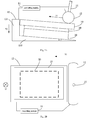
- Fig. 1A is a schematic diagram showing a system for controlling adhesion, according to an illustrative embodiment
- Fig. 1B is another schematic diagram showing a system for controlling adhesion, according to an illustrative embodiment.
- the TP 10 may be moved by a mechanical hand to be above the LCD 30, and the TP 10 is adhered to the LCD 30 with optical clear adhesive (OCA) 20 at a predetermined adhering angle, thus facilitating the adhesion.
- OCA optical clear adhesive
- the system for controlling adhesion includes: a controlling module 11, an adhering roller 12, and a limiting device 13.
- the controlling module 11 is configured to determine a first moving speed of the adhering roller 12 and a second moving speed of the limiting device 13.
- the adhering roller 12 is configured to roll along a first direction (indicated by an arrow direction of V 1 which is parallel to the TP 10) from one side to the other side of the TP 10 at the first moving speed.
- the controlling module 11 controls a rotation speed of a first stepping motor (not shown), so as to control the adhering roller 12 to roll at the first moving speed V 1 .
- the limiting device 13 is configured to along a second direction (indicated by an arrow direction of V 2 which is parallel to a side wall of the limiting device 13) at a second moving speed and limit the TP 10 to move with respect to the LCD 30.
- the controlling module 11 controls a rotation speed of a second stepping motor (not shown), so as to control the limiting device 13 to move at the second moving speed V 2 .
- Fig. 1A merely illustratively indicates that the arrow direction of V 2 is of a vertical direction at the very moment shown as Fig. 1A .
- the arrow direction of V 2 is further of an inclined direction with respect to the vertical direction at other moving moments, i.e., the arrow direction of V 2 is variable, for example, the arrow direction of V 2 may be of a tangential direction along an arc.
- the second moving direction may be a tangential direction.
- the adhering roller 12 is rolled along the first direction from one side to the other side of the TP10, so as to discharge bubbles between the TP 10 and the LCD 30, and thereby improving adhesion speed of optical bonding process.
- the TP 10 is limited by the limiting device 13 during the entire adhesion process, thus preventing relative movement between the TP 10 and the LCD 30, guaranteeing adhering accuracy, and thereby improving adhesion productivity to a great extend under limited plant and equipment investment.
- the limiting device may include:
- controlling module may include:
- the system further includes an air pressure regulating valve, configured to apply force on two axial ends of the adhering roller, so as to adjusting force applied by the adhering roller along a direction vertical to the TP under control of the controlling module.
- the above described system may discharge bubbles between the TP and the LCD, thus improving adhesion speed of optical bonding process, preventing relative movement therebetween during adhering the TP and the LCD, guaranteeing adhering accuracy, and thereby improving adhesion productivity to a great extend under limited plant and equipment investment.
- Fig. 2A is a schematic diagram showing a system for controlling adhesion, according to an illustrative example
- Fig. 2B is another schematic diagram showing a system for controlling adhesion, according to an illustrative example.
- the present example is based on the above described embodiments.
- the limiting device 13 includes:
- controlling module 11 may include:
- the predetermined angle whose size is not limited by examples of the present disclosure, may be set in accordance with a material of the OCA, and thicknesses of the TP 10 and the LCD 30.
- the supporting surface of the supporting portion 132 gradually becomes horizontal from the predetermined angle, it may enable the TP 10 and the LCD 30 to be maintained horizontal after being adhered, and prevent the TP 10 and the LCD 30 from deformation induced by external anomaly pressure.
- the system for controlling adhesion may further include: an air pressure regulating valve 14, configured to apply force on two axial end of the adhering roller 12, so as to enable the entire adhering roller 12 to be evenly stressed along an axial direction of its own, and thereby adjusting force applied by the adhering roller 12 along a direction vertical to the TP under control of the controlling module 11.
- an air pressure regulating valve 14 configured to apply force on two axial end of the adhering roller 12, so as to enable the entire adhering roller 12 to be evenly stressed along an axial direction of its own, and thereby adjusting force applied by the adhering roller 12 along a direction vertical to the TP under control of the controlling module 11.
- the force applied by the adhering roller 12 along the direction vertical to the TP 10 is of an arrow direction shown as F.
- the force (shown as F) applied by the adhering roller 12 onto the TP 10 may be adjusted by the air pressure regulating valve 14.
- the air pressure regulating valve 14 may adjust the force to be capable of discharging the bubble
- a position at which the air pressure regulating valve 14 is located is not limited by embodiments of the present disclosure, i.e., the air pressure regulating valve 14 may be arranged in the middle of the adhering roller 12 (illustratively shown in Fig. 2B ), or disposed at two ends of the adhering roller 12 (not shown), as long as it may enable the adhering roller 12 to be evenly stressed along the axial direction of its own.
- the supporting surface of the supporting portion 132 may become horizontal from the predetermined angle, so as to enable the TP 10 and the LCD 30 to be maintained horizontal after being adhered, and thus preventing the TP 10 and the LCD 30 from deformation induced by external anomalous pressure.
- the force may be adjusted by the air pressure regulating valve 14 to be capable of discharging the bubbles between the TP 10 and the LCD 30 without inducing deformation to the TP 10.
- productivity may be increased to 180 to 200 pieces per hour by the system provided by embodiments of the present disclosure, as compared with that of 70 to 120 pieces per hour in the related art, which effectively overcomes the productivity bottle neck under limited plant and equipment investment.
- Fig. 3 is a flow chart showing a method for controlling adhesion, according to an illustrative embodiment.
- a touch panel (TP) is adhered to a liquid crystal display (LCD) with optical clear adhesive (OCA) at a predetermined adhering angle.
- OCA optical clear adhesive
- the method for controlling adhesion includes the following steps S301-S303.
- step S301 a first moving speed of an adhering roller and a second moving speed of a limiting device are determined.
- step S302 the adhering roller is controlled to roll along a first direction from one side to the other side of the TP at the first moving speed.
- step S303 the TP is limited to move with respect to the LCD by a limiting device, and the limiting device is controlled to move along a second direction at the second moving speed.
- step S303 may include:
- determining the first moving speed of the adhering roller and the second moving speed of the limiting device may include:
- the method may further include:
- Fig. 4 is a block diagram of a device suitable for controlling adhesion, according to an illustrative embodiment.
- the device 400 may be provided as a server or a main control device.
- the device 400 includes a processing component 422, which further includes one or more processor, and a memory resource represented by a memory 432, for storing an instruction executable by the processing component 422, for example, application program.
- the application program stored in the memory 432 may include one or more modules, each corresponding to a group of instructions.
- the processing component 422 is configured to execute the instruction, so as to determine the first moving speed of the adhering roller and the second moving speed of the limiting device.
- the device 400 may further include a power component 424, configured to execute power management of the device 400; one wired or wireless network interface 450, configured to connect the device 400 to network; and one input/output (I/O) interface 458.
- the device 400 may be operated based on an operating system stored in the memory 432, such as Windows ServerTM, Mac OS XTM, UnixTM, LinuxTM, FreeBSDTM, or the like.
- modules are referred to in apparatus embodiments for carrying out various steps of the described method(s) it will be understood that these modules may be implemented in hardware, in software, or a combination of the two.
- the modules When implemented in hardware, the modules may be implemented as one or more hardware modules, such as one or more application specific integrated circuits.
- the modules When implemented in software, the modules may be implemented as one or more computer programs that are executed on one or more processors.
Landscapes
- Physics & Mathematics (AREA)
- Nonlinear Science (AREA)
- Engineering & Computer Science (AREA)
- General Physics & Mathematics (AREA)
- Chemical & Material Sciences (AREA)
- Crystallography & Structural Chemistry (AREA)
- Optics & Photonics (AREA)
- Fluid Mechanics (AREA)
- Manufacturing & Machinery (AREA)
- Quality & Reliability (AREA)
- Theoretical Computer Science (AREA)
- General Engineering & Computer Science (AREA)
- Mathematical Physics (AREA)
- Human Computer Interaction (AREA)
- Liquid Crystal (AREA)
- Devices For Indicating Variable Information By Combining Individual Elements (AREA)
- Adhesives Or Adhesive Processes (AREA)
- Lining Or Joining Of Plastics Or The Like (AREA)
Abstract
Description
- The present disclosure generally relates to the field of electronic product manufacturing technology, and more particularly, to a system, method and device for controlling adhesion.
- Along with increasing demands to optical property of display for a smart phone, it has been more and more popular to adhere a touch panel (TP) and a liquid crystal display (LCD) by optical bonding process. In the related art, after aligning a view area (VA) of the TP to an active area (AA) of LCD, a machine for holding the LCD is maintained still, and the TP adhered with optical clear adhesive (OCA) is moved by a mechanical hand so to be above the LCD. The adhesion between the TP and the LCD is performed in a vacuumed metal cavity.
- During adhering the TP to the LCD in the vacuumed metal cavity, as the TP is not fixed by a fixing device, relative movement between the TP and the LCD occurs along an X or Y direction in the vacuumed state. Besides, in order to completely discharge bubbles between the TP and the LCD, it requires a certain additional time to vacuum the metal cavity, thus resulting in low productivity.
- In order to overcome the problem existing in the related art, the present disclosure provides a system, method and device for controlling adhesion, so as to effectively discharge bubbles between a TP and a LCD, and thereby preventing relative movement between the TP and the LCD during adhesion.
- According to a first aspect of embodiments of the present disclosure, there is provided a system for controlling adhesion. A touch panel (TP) is adhered to a liquid crystal display (LCD) with optical clear adhesive (OCA) at a predetermined adhering angle. The system for controlling adhesion includes: a controlling module, an adhering roller and a limiting device.
- The controlling module is configured to determine a first moving speed of the adhering roller and a second moving speed of the limiting device.
- The adhering roller is configured to roll along a first direction from one side to the other side of the TP at the first moving speed.
- The limiting device is configured to move along a second direction at the second moving speed and limit the TP to move with respect to the LCD.
- In an embodiment, the limiting device may include:
- a limiting portion, configured to limit the TP to move with respect to the LCD; and
- a supporting portion, having a supporting surface at a predetermined angle with respect to a horizontal plane, and the LCD is supported on the supporting surface,
- in which the limiting device is moved along the second direction at the second moving speed, so as to enable the supporting surface and the LCD to become horizontal from the predetermined angle.
- In an embodiment, the controlling module includes:
- an acquiring sub-module, configured to acquire the predetermined angle with respect to the horizontal plane; and
- a speed controlling sub-module, configured to control the adhering roller to move at the first moving speed and the limiting device to move at the second moving speed in accordance with a sine value of the predetermined angle.
- In an embodiment, the first moving speed and the second moving speed meet a formula below:

- In an embodiment, the system further may include an air pressure regulating valve, configured to apply force on two axial ends of the adhering roller, so as to adjust force applied by the adhering roller along a direction vertical to the TP under control of the controlling module.
- According to a second aspect of embodiments of the present disclosure, there is provided a method for controlling adhesion. A touch panel (TP) is adhered to a liquid crystal display (LCD) with optical clear adhesive (OCA) at a predetermined adhering angle. The method may include:
- determining a first moving speed of an adhering roller and a second moving speed of a limiting device;
- controlling the adhering roller to roll along a first direction from one side to the other side of the TP at the first moving speed; and
- limiting the TP to move with respect to a liquid crystal display (LCD) by a limiting device, and controlling the limiting device to move along a second direction at the second moving speed.
- In an embodiment, limiting the TP to move with respect to a LCD by a limiting device, and controlling the limiting device to move along a second direction at the second moving speed may include:
- limiting the TP to move with respect to the LCD by a limiting portion of the limiting device; and
- controlling the limiting device to move along the second direction at the second moving speed, in which the limiting device has a supporting surface at a predetermined angle with respect to a horizontal plane and the LCD is supported on the supporting surface, so as to enable the supporting surface and the LCD to become horizontal from the predetermined angle.
- In an embodiment, determining a first moving speed of an adhering roller and a second moving speed of a limiting device may include:
- acquiring the predetermined angle; and
- controlling the adhering roller to move at the first moving speed and the limiting device to move at the second moving speed in accordance with a sine value of the predetermined angle.
- In an embodiment, the first moving speed and the second moving speed meet a formula as below:

- In an embodiment, the method may further include:
- applying force on two axial ends of the adhering roller by an air pressure regulating valve, and
- adjusting force applied by the adhering roller along the direction vertical to the TP.
- According to a third aspect of embodiments of the present disclosure, there is provided a device for controlling adhesion. The device may include:
- a processor;
- a memory for storing instructions executable by the processor; and
- a controlling module, configured to determine a first moving speed of an adhering roller and a second moving speed of a limiting device.
- According to embodiments of the present disclosure, the technical solution may have the following advantageous effects. The adhering roller is rolled from one side to the other side of the TP, so as to discharge bubbles between the TP and the LCD, thus increasing adhesion speed of the optical bonding process. The TP is limited by the limiting device during the entire adhesion process, thus preventing relative movement between the TP and the LCD, guaranteeing adhering accuracy, and thereby improving adhesion productivity to a great extend under limited plant and equipment investment.
- It is to be understood that both the foregoing general description and the following detailed description are illustrative and explanatory only and are not restrictive of the disclosure, as claimed.
- The accompanying drawings, which are incorporated in and constitute a part of this specification, illustrate embodiments consistent with the disclosure and, together with the description, serve to explain the principles of the disclosure.
-
Fig. 1A is a schematic diagram showing a system for controlling adhesion, according to an illustrative embodiment; -
Fig. 1B is another schematic diagram showing a system for controlling adhesion, according to an illustrative embodiment; -
Fig. 2A is a schematic diagram showing a system for controlling adhesion, according to an illustrative example; -
Fig. 2B is another schematic diagram showing a system for controlling adhesion, according to an illustrative example; -
Fig. 3 is a flow chart showing a method for controlling adhesion, according to an illustrative embodiment; and -
Fig. 4 is a block diagram of a device suitable for controlling adhesion, according to an illustrative embodiment. - Reference will now be made in detail to illustrative embodiments, examples of which are illustrated in the accompanying drawings. The following description refers to the accompanying drawings in which the same numbers in different drawings represent the same or similar elements unless otherwise represented. The implementations set forth in the following description of illustrative embodiments do not represent all implementations consistent with the disclosure. Instead, they are merely examples of apparatuses and methods consistent with aspects related to the disclosure as recited in the appended claims.
-
Fig. 1A is a schematic diagram showing a system for controlling adhesion, according to an illustrative embodiment, andFig. 1B is another schematic diagram showing a system for controlling adhesion, according to an illustrative embodiment. As shown inFigs. 1A and 1B , after a touch panel (TP) 10 and a liquid crystal display (LCD) 30 are aligned, theTP 10 may be moved by a mechanical hand to be above theLCD 30, and theTP 10 is adhered to theLCD 30 with optical clear adhesive (OCA) 20 at a predetermined adhering angle, thus facilitating the adhesion. The system for controlling adhesion includes: a controllingmodule 11, an adheringroller 12, and a limitingdevice 13. - The controlling
module 11 is configured to determine a first moving speed of the adheringroller 12 and a second moving speed of the limitingdevice 13. - The adhering
roller 12 is configured to roll along a first direction (indicated by an arrow direction of V 1 which is parallel to the TP 10) from one side to the other side of theTP 10 at the first moving speed. In an embodiment, the controllingmodule 11 controls a rotation speed of a first stepping motor (not shown), so as to control the adheringroller 12 to roll at the first moving speed V 1. - The limiting
device 13 is configured to along a second direction (indicated by an arrow direction of V 2 which is parallel to a side wall of the limiting device 13) at a second moving speed and limit theTP 10 to move with respect to theLCD 30. In an embodiment, the controllingmodule 11 controls a rotation speed of a second stepping motor (not shown), so as to control the limitingdevice 13 to move at the second moving speed V 2. - In specific,
Fig. 1A merely illustratively indicates that the arrow direction of V 2 is of a vertical direction at the very moment shown asFig. 1A . It would be appreciated by those skilled in the art that the arrow direction of V 2 is further of an inclined direction with respect to the vertical direction at other moving moments, i.e., the arrow direction of V 2 is variable, for example, the arrow direction of V 2 may be of a tangential direction along an arc. In another word, the second moving direction may be a tangential direction. - In the present embodiment, the adhering
roller 12 is rolled along the first direction from one side to the other side of the TP10, so as to discharge bubbles between theTP 10 and theLCD 30, and thereby improving adhesion speed of optical bonding process. TheTP 10 is limited by the limitingdevice 13 during the entire adhesion process, thus preventing relative movement between theTP 10 and theLCD 30, guaranteeing adhering accuracy, and thereby improving adhesion productivity to a great extend under limited plant and equipment investment. - In an embodiment, the limiting device may include:
- a limiting portion, configured to limit the TP to move with respect to the LCD; and
- a supporting portion, having a supporting surface at a predetermined angle with respect to a horizontal plane, and the LCD being supported on the supporting surface,
- in which the limiting device is moved along the second direction at the second moving speed, so as to enable the supporting surface and the LCD to become horizontal from the predetermined angle.
- In an embodiment, the controlling module may include:
- an acquiring sub-module, configured to acquire the predetermined angle with respect to the horizontal plane; and
- a speed controlling sub-module, configured to control the adhering roller to move at the first moving speed and the limiting device to move at the second moving speed in accordance with a sine value of the predetermined angle.
- In an embodiment, the first moving speed and the second moving speed meet formula as below:

- In an embodiment, the system further includes an air pressure regulating valve, configured to apply force on two axial ends of the adhering roller, so as to adjusting force applied by the adhering roller along a direction vertical to the TP under control of the controlling module.
- Reference will be made below on how to adhere the TP and the LCD in detail.
- According to embodiments of the present disclosure, the above described system may discharge bubbles between the TP and the LCD, thus improving adhesion speed of optical bonding process, preventing relative movement therebetween during adhering the TP and the LCD, guaranteeing adhering accuracy, and thereby improving adhesion productivity to a great extend under limited plant and equipment investment.
- The technical solution provided by embodiments of the present disclosure will be illustrated with specific examples hereinafter.
-
Fig. 2A is a schematic diagram showing a system for controlling adhesion, according to an illustrative example, andFig. 2B is another schematic diagram showing a system for controlling adhesion, according to an illustrative example. The present example is based on the above described embodiments. As shown inFigs. 2A and 2B , the limitingdevice 13 includes: - a limiting
portion 131, configured to limit theTP 10 to move with respect to theLCD 30; and - a supporting
portion 132, having a supporting surface at a predetermined angle with respect to a horizontal plane (indicated as α ), and the LCD being supported on the supporting surface, - in which the limiting
device 13 is moved along the second direction at the second moving speed, so as to enable the supporting surface and the LCD to become horizontal. - In an embodiment, the controlling
module 11 may include: - an acquiring sub-module 111, configured to acquire the predetermined angle with respect to the horizontal plane; and
- a speed controlling sub-module 112, configured to control the adhering roller to move at the first moving speed and the limiting device to move at the second moving speed in accordance with a sine value of the predetermined angle acquired by the acquiring sub-module 111.
- In an embodiment, the predetermined angle, whose size is not limited by examples of the present disclosure, may be set in accordance with a material of the OCA, and thicknesses of the
TP 10 and theLCD 30. - In an embodiment, the first moving speed and the second moving speed meet a formula as below:
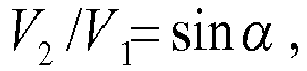
- The first moving speed V 1 and the second moving speed V 2 are adjusted to be in conformity with the above formula V 2/V 1= sin α, so as to ensure the
entire TP 10 being evenly rolled by the adheringroller 12 when the adheringroller 12 is rolled along the first direction (the right side in Figs.), from one side to the other side of theTP 10. After the supporting surface of the supportingportion 132 gradually becomes horizontal from the predetermined angle, it may enable theTP 10 and theLCD 30 to be maintained horizontal after being adhered, and prevent theTP 10 and theLCD 30 from deformation induced by external anomaly pressure. - In an embodiment, the system for controlling adhesion may further include: an air
pressure regulating valve 14, configured to apply force on two axial end of the adheringroller 12, so as to enable the entire adheringroller 12 to be evenly stressed along an axial direction of its own, and thereby adjusting force applied by the adheringroller 12 along a direction vertical to the TP under control of the controllingmodule 11. As shown inFig. 2A , the force applied by the adheringroller 12 along the direction vertical to theTP 10 is of an arrow direction shown as F. The force (shown as F) applied by the adheringroller 12 onto theTP 10 may be adjusted by the airpressure regulating valve 14. In an embodiment, the airpressure regulating valve 14 may adjust the force to be capable of discharging the bubbles between theTP 10 and theLCD 30 without inducing deformation to theTP 10. - In specific, a position at which the air
pressure regulating valve 14 is located is not limited by embodiments of the present disclosure, i.e., the airpressure regulating valve 14 may be arranged in the middle of the adhering roller 12 (illustratively shown inFig. 2B ), or disposed at two ends of the adhering roller 12 (not shown), as long as it may enable the adheringroller 12 to be evenly stressed along the axial direction of its own. - In an embodiment, on the basis of the advantageous technical effect of the above embodiments, it may allow the supporting surface of the supporting
portion 132 to become horizontal from the predetermined angle, so as to enable theTP 10 and theLCD 30 to be maintained horizontal after being adhered, and thus preventing theTP 10 and theLCD 30 from deformation induced by external anomalous pressure. The force may be adjusted by the airpressure regulating valve 14 to be capable of discharging the bubbles between theTP 10 and theLCD 30 without inducing deformation to theTP 10. - Besides, it has been demonstrated by relevant experimental data that productivity may be increased to 180 to 200 pieces per hour by the system provided by embodiments of the present disclosure, as compared with that of 70 to 120 pieces per hour in the related art, which effectively overcomes the productivity bottle neck under limited plant and equipment investment.
-
Fig. 3 is a flow chart showing a method for controlling adhesion, according to an illustrative embodiment. A touch panel (TP) is adhered to a liquid crystal display (LCD) with optical clear adhesive (OCA) at a predetermined adhering angle. As shown inFig. 3 , the method for controlling adhesion includes the following steps S301-S303. - In step S301, a first moving speed of an adhering roller and a second moving speed of a limiting device are determined.
- In step S302, the adhering roller is controlled to roll along a first direction from one side to the other side of the TP at the first moving speed.
- In step S303, the TP is limited to move with respect to the LCD by a limiting device, and the limiting device is controlled to move along a second direction at the second moving speed.
- In an embodiment, step S303 may include:
- limiting the TP to move with respect to the LCD by a limiting portion of the limiting device; and
- controlling the limiting device to move along the second direction at the second moving speed, in which the limiting device has a supporting surface at a predetermined angle with respect to a horizontal plane, and the LCD is supported on the supporting surface, so as to enable the supporting surface to become horizontal from the predetermined angle.
- In an embodiment, determining the first moving speed of the adhering roller and the second moving speed of the limiting device may include:
- acquiring the predetermined angle; and
- controlling the adhering roller to move at the first moving speed and the limiting device to move at the second moving speed in accordance with a sine value of the predetermined angle.
- In an embodiment, the first moving speed and the second moving speed meet a formula as below:

- In an embodiment, the method may further include:
- applying force on two axial ends of the adhering roller by an air pressure regulating valve, and
- adjusting force applied by the adhering roller along the direction vertical to the TP.
- Regarding procedures for the method in the above embodiments, specific modes for executing various steps has been described in detail in respect with the system for controlling adhesion in the above embodiment, which are not repeated herein.
-
Fig. 4 is a block diagram of a device suitable for controlling adhesion, according to an illustrative embodiment. For example, thedevice 400 may be provided as a server or a main control device. Referring toFig. 4 , thedevice 400 includes aprocessing component 422, which further includes one or more processor, and a memory resource represented by amemory 432, for storing an instruction executable by theprocessing component 422, for example, application program. The application program stored in thememory 432 may include one or more modules, each corresponding to a group of instructions. Besides, theprocessing component 422 is configured to execute the instruction, so as to determine the first moving speed of the adhering roller and the second moving speed of the limiting device. - The
device 400 may further include a power component 424, configured to execute power management of thedevice 400; one wired orwireless network interface 450, configured to connect thedevice 400 to network; and one input/output (I/O)interface 458. Thedevice 400 may be operated based on an operating system stored in thememory 432, such as Windows ServerTM, Mac OS XTM, UnixTM, LinuxTM, FreeBSDTM, or the like. - Where functional modules are referred to in apparatus embodiments for carrying out various steps of the described method(s) it will be understood that these modules may be implemented in hardware, in software, or a combination of the two. When implemented in hardware, the modules may be implemented as one or more hardware modules, such as one or more application specific integrated circuits. When implemented in software, the modules may be implemented as one or more computer programs that are executed on one or more processors.
- Other embodiments of the disclosure will be apparent to those skilled in the art from consideration of the specification and practice of the disclosure disclosed here. This application is intended to cover any variations, uses, or adaptations of the disclosure following the general principles thereof and including such departures from the present disclosure as come within known or customary practice in the art.
Claims (12)
- A system for controlling adhesion, comprising a controlling module (11), an adhering roller (12) and a limiting device (13), wherein
the controlling module (11) is configured to determine a first moving speed of the adhering roller (12) and a second moving speed of the limiting device (13);
the adhering roller (12) is configured to roll along a first direction from one side to the other side of a touch panel, TP at the first moving speed; and
the limiting device (13) is configured to move along a second direction at the second moving speed and to limit the TP to move with respect to a liquid crystal display, LCD. - The system of claim 1, wherein the limiting device (13) comprises:a limiting portion (131), configured to limit the TP to move with respect to the LCD; anda supporting portion (132), having a supporting surface at a predetermined angle with respect to a horizontal plane, and the LCD being supported on the supporting surface,wherein the limiting device (13) is moved along the second direction at the second moving speed, so as to enable the supporting surface and the LCD to become horizontal from the predetermined angle.
- The system of claim 2, wherein the controlling module (11) comprises:an acquiring sub-module (111), configured to acquire the predetermined angle; anda speed controlling sub-module (112), configured to control the adhering roller (12) to move at the first moving speed and the limiting device (13) to move at the second moving speed in accordance with a sine value of the predetermined angle.
- The system of claim 2 or claim 3, wherein the first moving speed and the second moving speed meet a formula:

- The system of any preceding claim, further comprising:an air pressure regulating valve (14), configured to apply force on two axial ends of the adhering roller (12), so as to adjust a force applied by the adhering roller (12) along a direction vertical to the TP under control of the controlling module.
- A method for controlling adhesion, comprising:determining a first moving speed of an adhering roller and a second moving speed of a limiting device;controlling the adhering roller to roll along a first direction from one side to the other side of a touch panel, TP, at the first moving speed; andlimiting the TP to move with respect to a liquid crystal display, LCD, by a limiting device, and controlling the limiting device to move along a second direction at the second moving speed.
- The method of claim 6, wherein limiting the TP to move with respect to the LCD by a limiting device, and controlling the limiting device to move along a second direction at the second moving speed comprises:limiting the TP to move with respect to the LCD by a limiting portion of the limiting device; andcontrolling the limiting device to move along the second direction at the second moving speed, in which the limiting device has a supporting surface at a predetermined angle with respect to a horizontal plane, and the LCD is supported on the supporting surface, so as to enable the supporting surface and the LCD to become horizontal from the predetermined angle.
- The method of claim 7, wherein determining a first moving speed of an adhering roller and a second moving speed of a limiting device comprises:acquiring the predetermined angle; andcontrolling the adhering roller to move at the first moving speed and the limiting device to move at the second moving speed in accordance with a sine value of the predetermined angle.
- The method of claim 7 or claim 8, wherein the first moving speed and the second moving speed meet a formula:

- The method of any of claims 6 to 9, further comprising:applying force on two axial ends of the adhering roller by an air pressure regulating valve, andadjusting force applied by the adhering roller along a direction vertical to the TP.
- A device for controlling adhesion, comprising:a processor;a memory for storing instructions executable by the processor; anda controlling module, configured to determine a first moving speed of an adhering roller and a second moving speed of a limiting device.
- A computer program, which when executing on a processor, performs a method according to any of claims 6 to 10.
Applications Claiming Priority (1)
| Application Number | Priority Date | Filing Date | Title |
|---|---|---|---|
| CN201510146179.6A CN104691086B (en) | 2015-03-30 | 2015-03-30 | Attachment control system, method and device |
Publications (2)
| Publication Number | Publication Date |
|---|---|
| EP3075534A1 true EP3075534A1 (en) | 2016-10-05 |
| EP3075534B1 EP3075534B1 (en) | 2018-03-14 |
Family
ID=53338815
Family Applications (1)
| Application Number | Title | Priority Date | Filing Date |
|---|---|---|---|
| EP16151314.8A Active EP3075534B1 (en) | 2015-03-30 | 2016-01-14 | System, method and computer program for controlling adhesion |
Country Status (8)
| Country | Link |
|---|---|
| US (1) | US9989789B2 (en) |
| EP (1) | EP3075534B1 (en) |
| JP (1) | JP6243086B2 (en) |
| KR (1) | KR101822770B1 (en) |
| CN (1) | CN104691086B (en) |
| MX (1) | MX2016007141A (en) |
| RU (1) | RU2654005C1 (en) |
| WO (1) | WO2016155307A1 (en) |
Families Citing this family (4)
| Publication number | Priority date | Publication date | Assignee | Title |
|---|---|---|---|---|
| CN104691086B (en) * | 2015-03-30 | 2017-02-01 | 小米科技有限责任公司 | Attachment control system, method and device |
| CN105892107A (en) * | 2016-04-15 | 2016-08-24 | 京东方科技集团股份有限公司 | Automatic laminating equipment and automatic laminating method |
| CN106364123B (en) * | 2016-08-26 | 2018-02-06 | 京东方科技集团股份有限公司 | Lamination equipment and lamination method |
| CN113093415B (en) * | 2021-04-02 | 2024-04-12 | 曲面超精密光电(深圳)有限公司 | Special special-shaped plane full-lamination equipment and method |
Citations (2)
| Publication number | Priority date | Publication date | Assignee | Title |
|---|---|---|---|---|
| CN103029409A (en) * | 2011-10-03 | 2013-04-10 | 株式会社石山制作所 | Sticking apparatus |
| US20140116598A1 (en) * | 2012-10-26 | 2014-05-01 | Samsung Display Co., Ltd. | Apparatus and method of laminating adhesive film |
Family Cites Families (11)
| Publication number | Priority date | Publication date | Assignee | Title |
|---|---|---|---|---|
| JPH0412849A (en) * | 1990-04-28 | 1992-01-17 | Somar Corp | Laminator |
| JP3083423B2 (en) * | 1993-03-02 | 2000-09-04 | アルプス電気株式会社 | Adhesion method and adhesion device between substrate and film |
| JP2002207435A (en) * | 2001-01-04 | 2002-07-26 | Minolta Co Ltd | Method and device for manufacturing display device |
| JP4124022B2 (en) * | 2003-01-23 | 2008-07-23 | ソニー株式会社 | Bonding apparatus and bonding method |
| JP2008122454A (en) * | 2006-11-08 | 2008-05-29 | Tamura Seisakusho:Kk | Attaching device |
| JP5151326B2 (en) * | 2007-09-04 | 2013-02-27 | Nltテクノロジー株式会社 | Vacuum adsorption control mechanism device, film sticking device, display device |
| SG190467A1 (en) * | 2011-11-22 | 2013-06-28 | Trimech Technology Pte Ltd | A laminated product, an apparatus and a method for forming a laminated product |
| KR101190992B1 (en) * | 2012-02-14 | 2012-10-16 | 주식회사 씨엘케이 | Attaching device for touch panel and manufacturing method thereof |
| JP5311527B1 (en) * | 2013-04-04 | 2013-10-09 | 株式会社Fuk | Pasting device |
| CN103879587B (en) | 2014-03-14 | 2016-04-20 | 东莞市上川自动化设备有限公司 | A kind of Full-automatic film sticking machine |
| CN104691086B (en) * | 2015-03-30 | 2017-02-01 | 小米科技有限责任公司 | Attachment control system, method and device |
-
2015
- 2015-03-30 CN CN201510146179.6A patent/CN104691086B/en active Active
- 2015-10-30 JP JP2017508744A patent/JP6243086B2/en active Active
- 2015-10-30 MX MX2016007141A patent/MX2016007141A/en active IP Right Grant
- 2015-10-30 WO PCT/CN2015/093414 patent/WO2016155307A1/en not_active Ceased
- 2015-10-30 RU RU2016123833A patent/RU2654005C1/en active
- 2015-10-30 KR KR1020167015988A patent/KR101822770B1/en active Active
-
2016
- 2016-01-14 EP EP16151314.8A patent/EP3075534B1/en active Active
- 2016-02-26 US US15/054,262 patent/US9989789B2/en active Active
Patent Citations (2)
| Publication number | Priority date | Publication date | Assignee | Title |
|---|---|---|---|---|
| CN103029409A (en) * | 2011-10-03 | 2013-04-10 | 株式会社石山制作所 | Sticking apparatus |
| US20140116598A1 (en) * | 2012-10-26 | 2014-05-01 | Samsung Display Co., Ltd. | Apparatus and method of laminating adhesive film |
Non-Patent Citations (1)
| Title |
|---|
| ANONYMOUS: "One Glass Solution", WIKIPEDIA, 11 March 2015 (2015-03-11), XP055295930, Retrieved from the Internet <URL:http://web.archive.org/web/20150311143339/http://en.wikipedia.org/wiki/One_Glass_Solution> [retrieved on 20160817] * |
Also Published As
| Publication number | Publication date |
|---|---|
| RU2654005C1 (en) | 2018-05-15 |
| WO2016155307A1 (en) | 2016-10-06 |
| KR101822770B1 (en) | 2018-03-08 |
| CN104691086B (en) | 2017-02-01 |
| KR20160127716A (en) | 2016-11-04 |
| JP6243086B2 (en) | 2017-12-06 |
| MX2016007141A (en) | 2016-12-09 |
| US20160291356A1 (en) | 2016-10-06 |
| JP2017516249A (en) | 2017-06-15 |
| US9989789B2 (en) | 2018-06-05 |
| CN104691086A (en) | 2015-06-10 |
| EP3075534B1 (en) | 2018-03-14 |
| RU2016123833A (en) | 2017-12-21 |
Similar Documents
| Publication | Publication Date | Title |
|---|---|---|
| EP3075534A1 (en) | System, method and device for controlling adhesion | |
| US10870267B2 (en) | Peeling bar for peeling polarizing film from panel, peeling apparatus and peeling method using the same | |
| US8965552B2 (en) | Method and a device for titling | |
| SG152291A1 (en) | Stage drive method and stage unit, exposure apparatus, and device manufacturing method | |
| JP2014151398A5 (en) | Spectacle lens peripheral processing system, spectacle lens peripheral processing program, and spectacle lens peripheral processing apparatus | |
| US20160318295A1 (en) | A device for tearing off a polarizer and method thereof | |
| CN103258509A (en) | Resolution ratio adjusting method and electronic equipment | |
| US10195628B2 (en) | Clamping apparatus and method of manufacturing a mask using the same | |
| US20160358806A1 (en) | Apparatus of separating flexible substrate from glass substrate and manufacturing equipment thereof | |
| EP2963461A3 (en) | Polarizing plate, liquid crystal display device having the same and method of fabricating the polarizing plate | |
| EP3940685A4 (en) | PANEL AND DISPLAY DEVICE AND CONTROL METHOD FOR DISPLAY PANEL | |
| US20150234326A1 (en) | Developing device and developing method | |
| EP3961615A4 (en) | Image display device, image display system, image display method, and computer program | |
| EP4242975A3 (en) | Image processing method and display apparatus therefor | |
| CN105612229B (en) | Component bonding apparatus and method | |
| US11850621B2 (en) | Edge blackening for optical devices | |
| JP4488500B2 (en) | Mask deflection correction device | |
| CN115847997A (en) | Laminating jig and laminating method for curved screen, bearing film and curved screen | |
| EP4227802A4 (en) | Method, apparatus and computing device for configuring compute mode | |
| US20130156954A1 (en) | Roller making system and method | |
| Wang et al. | On the Robust Control of Compliantly Actuated Robots With Mismatched Disturbances | |
| WO2016041268A1 (en) | Method for affixing polariser onto glass substrate of flat-panel display | |
| JP2015066530A (en) | Resin coating apparatus and resin coating method | |
| KR101282589B1 (en) | Substrate transfer apparatus and substrate transfer method | |
| EP4411355A4 (en) | Image processing device, processing system, image display method, and program |
Legal Events
| Date | Code | Title | Description |
|---|---|---|---|
| PUAI | Public reference made under article 153(3) epc to a published international application that has entered the european phase |
Free format text: ORIGINAL CODE: 0009012 |
|
| AK | Designated contracting states |
Kind code of ref document: A1 Designated state(s): AL AT BE BG CH CY CZ DE DK EE ES FI FR GB GR HR HU IE IS IT LI LT LU LV MC MK MT NL NO PL PT RO RS SE SI SK SM TR |
|
| AX | Request for extension of the european patent |
Extension state: BA ME |
|
| STAA | Information on the status of an ep patent application or granted ep patent |
Free format text: STATUS: REQUEST FOR EXAMINATION WAS MADE |
|
| 17P | Request for examination filed |
Effective date: 20170405 |
|
| RBV | Designated contracting states (corrected) |
Designated state(s): AL AT BE BG CH CY CZ DE DK EE ES FI FR GB GR HR HU IE IS IT LI LT LU LV MC MK MT NL NO PL PT RO RS SE SI SK SM TR |
|
| STAA | Information on the status of an ep patent application or granted ep patent |
Free format text: STATUS: EXAMINATION IS IN PROGRESS |
|
| 17Q | First examination report despatched |
Effective date: 20170913 |
|
| RIC1 | Information provided on ipc code assigned before grant |
Ipc: B32B 37/10 20060101AFI20170918BHEP Ipc: G02F 1/13 20060101ALN20170918BHEP Ipc: B32B 38/18 20060101ALI20170918BHEP |
|
| GRAP | Despatch of communication of intention to grant a patent |
Free format text: ORIGINAL CODE: EPIDOSNIGR1 |
|
| STAA | Information on the status of an ep patent application or granted ep patent |
Free format text: STATUS: GRANT OF PATENT IS INTENDED |
|
| RIC1 | Information provided on ipc code assigned before grant |
Ipc: B32B 38/18 20060101ALI20171004BHEP Ipc: B32B 37/10 20060101AFI20171004BHEP Ipc: G02F 1/13 20060101ALN20171004BHEP |
|
| INTG | Intention to grant announced |
Effective date: 20171103 |
|
| GRAS | Grant fee paid |
Free format text: ORIGINAL CODE: EPIDOSNIGR3 |
|
| GRAA | (expected) grant |
Free format text: ORIGINAL CODE: 0009210 |
|
| STAA | Information on the status of an ep patent application or granted ep patent |
Free format text: STATUS: THE PATENT HAS BEEN GRANTED |
|
| AK | Designated contracting states |
Kind code of ref document: B1 Designated state(s): AL AT BE BG CH CY CZ DE DK EE ES FI FR GB GR HR HU IE IS IT LI LT LU LV MC MK MT NL NO PL PT RO RS SE SI SK SM TR |
|
| REG | Reference to a national code |
Ref country code: GB Ref legal event code: FG4D |
|
| REG | Reference to a national code |
Ref country code: CH Ref legal event code: EP Ref country code: AT Ref legal event code: REF Ref document number: 978466 Country of ref document: AT Kind code of ref document: T Effective date: 20180315 |
|
| REG | Reference to a national code |
Ref country code: IE Ref legal event code: FG4D |
|
| REG | Reference to a national code |
Ref country code: DE Ref legal event code: R096 Ref document number: 602016001895 Country of ref document: DE |
|
| REG | Reference to a national code |
Ref country code: NL Ref legal event code: MP Effective date: 20180314 |
|
| REG | Reference to a national code |
Ref country code: LT Ref legal event code: MG4D |
|
| PG25 | Lapsed in a contracting state [announced via postgrant information from national office to epo] |
Ref country code: FI Free format text: LAPSE BECAUSE OF FAILURE TO SUBMIT A TRANSLATION OF THE DESCRIPTION OR TO PAY THE FEE WITHIN THE PRESCRIBED TIME-LIMIT Effective date: 20180314 Ref country code: HR Free format text: LAPSE BECAUSE OF FAILURE TO SUBMIT A TRANSLATION OF THE DESCRIPTION OR TO PAY THE FEE WITHIN THE PRESCRIBED TIME-LIMIT Effective date: 20180314 Ref country code: NO Free format text: LAPSE BECAUSE OF FAILURE TO SUBMIT A TRANSLATION OF THE DESCRIPTION OR TO PAY THE FEE WITHIN THE PRESCRIBED TIME-LIMIT Effective date: 20180614 Ref country code: CY Free format text: LAPSE BECAUSE OF FAILURE TO SUBMIT A TRANSLATION OF THE DESCRIPTION OR TO PAY THE FEE WITHIN THE PRESCRIBED TIME-LIMIT Effective date: 20180314 Ref country code: LT Free format text: LAPSE BECAUSE OF FAILURE TO SUBMIT A TRANSLATION OF THE DESCRIPTION OR TO PAY THE FEE WITHIN THE PRESCRIBED TIME-LIMIT Effective date: 20180314 |
|
| REG | Reference to a national code |
Ref country code: AT Ref legal event code: MK05 Ref document number: 978466 Country of ref document: AT Kind code of ref document: T Effective date: 20180314 |
|
| PG25 | Lapsed in a contracting state [announced via postgrant information from national office to epo] |
Ref country code: GR Free format text: LAPSE BECAUSE OF FAILURE TO SUBMIT A TRANSLATION OF THE DESCRIPTION OR TO PAY THE FEE WITHIN THE PRESCRIBED TIME-LIMIT Effective date: 20180615 Ref country code: BG Free format text: LAPSE BECAUSE OF FAILURE TO SUBMIT A TRANSLATION OF THE DESCRIPTION OR TO PAY THE FEE WITHIN THE PRESCRIBED TIME-LIMIT Effective date: 20180614 Ref country code: RS Free format text: LAPSE BECAUSE OF FAILURE TO SUBMIT A TRANSLATION OF THE DESCRIPTION OR TO PAY THE FEE WITHIN THE PRESCRIBED TIME-LIMIT Effective date: 20180314 Ref country code: SE Free format text: LAPSE BECAUSE OF FAILURE TO SUBMIT A TRANSLATION OF THE DESCRIPTION OR TO PAY THE FEE WITHIN THE PRESCRIBED TIME-LIMIT Effective date: 20180314 Ref country code: LV Free format text: LAPSE BECAUSE OF FAILURE TO SUBMIT A TRANSLATION OF THE DESCRIPTION OR TO PAY THE FEE WITHIN THE PRESCRIBED TIME-LIMIT Effective date: 20180314 |
|
| PG25 | Lapsed in a contracting state [announced via postgrant information from national office to epo] |
Ref country code: PL Free format text: LAPSE BECAUSE OF FAILURE TO SUBMIT A TRANSLATION OF THE DESCRIPTION OR TO PAY THE FEE WITHIN THE PRESCRIBED TIME-LIMIT Effective date: 20180314 Ref country code: EE Free format text: LAPSE BECAUSE OF FAILURE TO SUBMIT A TRANSLATION OF THE DESCRIPTION OR TO PAY THE FEE WITHIN THE PRESCRIBED TIME-LIMIT Effective date: 20180314 Ref country code: NL Free format text: LAPSE BECAUSE OF FAILURE TO SUBMIT A TRANSLATION OF THE DESCRIPTION OR TO PAY THE FEE WITHIN THE PRESCRIBED TIME-LIMIT Effective date: 20180314 Ref country code: RO Free format text: LAPSE BECAUSE OF FAILURE TO SUBMIT A TRANSLATION OF THE DESCRIPTION OR TO PAY THE FEE WITHIN THE PRESCRIBED TIME-LIMIT Effective date: 20180314 Ref country code: AL Free format text: LAPSE BECAUSE OF FAILURE TO SUBMIT A TRANSLATION OF THE DESCRIPTION OR TO PAY THE FEE WITHIN THE PRESCRIBED TIME-LIMIT Effective date: 20180314 Ref country code: ES Free format text: LAPSE BECAUSE OF FAILURE TO SUBMIT A TRANSLATION OF THE DESCRIPTION OR TO PAY THE FEE WITHIN THE PRESCRIBED TIME-LIMIT Effective date: 20180314 |
|
| PG25 | Lapsed in a contracting state [announced via postgrant information from national office to epo] |
Ref country code: CZ Free format text: LAPSE BECAUSE OF FAILURE TO SUBMIT A TRANSLATION OF THE DESCRIPTION OR TO PAY THE FEE WITHIN THE PRESCRIBED TIME-LIMIT Effective date: 20180314 Ref country code: SK Free format text: LAPSE BECAUSE OF FAILURE TO SUBMIT A TRANSLATION OF THE DESCRIPTION OR TO PAY THE FEE WITHIN THE PRESCRIBED TIME-LIMIT Effective date: 20180314 Ref country code: AT Free format text: LAPSE BECAUSE OF FAILURE TO SUBMIT A TRANSLATION OF THE DESCRIPTION OR TO PAY THE FEE WITHIN THE PRESCRIBED TIME-LIMIT Effective date: 20180314 Ref country code: SM Free format text: LAPSE BECAUSE OF FAILURE TO SUBMIT A TRANSLATION OF THE DESCRIPTION OR TO PAY THE FEE WITHIN THE PRESCRIBED TIME-LIMIT Effective date: 20180314 |
|
| REG | Reference to a national code |
Ref country code: DE Ref legal event code: R097 Ref document number: 602016001895 Country of ref document: DE |
|
| PG25 | Lapsed in a contracting state [announced via postgrant information from national office to epo] |
Ref country code: PT Free format text: LAPSE BECAUSE OF FAILURE TO SUBMIT A TRANSLATION OF THE DESCRIPTION OR TO PAY THE FEE WITHIN THE PRESCRIBED TIME-LIMIT Effective date: 20180716 |
|
| PLBE | No opposition filed within time limit |
Free format text: ORIGINAL CODE: 0009261 |
|
| STAA | Information on the status of an ep patent application or granted ep patent |
Free format text: STATUS: NO OPPOSITION FILED WITHIN TIME LIMIT |
|
| PG25 | Lapsed in a contracting state [announced via postgrant information from national office to epo] |
Ref country code: DK Free format text: LAPSE BECAUSE OF FAILURE TO SUBMIT A TRANSLATION OF THE DESCRIPTION OR TO PAY THE FEE WITHIN THE PRESCRIBED TIME-LIMIT Effective date: 20180314 |
|
| 26N | No opposition filed |
Effective date: 20181217 |
|
| PG25 | Lapsed in a contracting state [announced via postgrant information from national office to epo] |
Ref country code: IT Free format text: LAPSE BECAUSE OF FAILURE TO SUBMIT A TRANSLATION OF THE DESCRIPTION OR TO PAY THE FEE WITHIN THE PRESCRIBED TIME-LIMIT Effective date: 20180314 Ref country code: SI Free format text: LAPSE BECAUSE OF FAILURE TO SUBMIT A TRANSLATION OF THE DESCRIPTION OR TO PAY THE FEE WITHIN THE PRESCRIBED TIME-LIMIT Effective date: 20180314 |
|
| PG25 | Lapsed in a contracting state [announced via postgrant information from national office to epo] |
Ref country code: MC Free format text: LAPSE BECAUSE OF FAILURE TO SUBMIT A TRANSLATION OF THE DESCRIPTION OR TO PAY THE FEE WITHIN THE PRESCRIBED TIME-LIMIT Effective date: 20180314 |
|
| REG | Reference to a national code |
Ref country code: CH Ref legal event code: PL |
|
| PG25 | Lapsed in a contracting state [announced via postgrant information from national office to epo] |
Ref country code: LU Free format text: LAPSE BECAUSE OF NON-PAYMENT OF DUE FEES Effective date: 20190114 |
|
| REG | Reference to a national code |
Ref country code: BE Ref legal event code: MM Effective date: 20190131 |
|
| REG | Reference to a national code |
Ref country code: IE Ref legal event code: MM4A |
|
| PG25 | Lapsed in a contracting state [announced via postgrant information from national office to epo] |
Ref country code: BE Free format text: LAPSE BECAUSE OF NON-PAYMENT OF DUE FEES Effective date: 20190131 |
|
| PG25 | Lapsed in a contracting state [announced via postgrant information from national office to epo] |
Ref country code: CH Free format text: LAPSE BECAUSE OF NON-PAYMENT OF DUE FEES Effective date: 20190131 Ref country code: LI Free format text: LAPSE BECAUSE OF NON-PAYMENT OF DUE FEES Effective date: 20190131 |
|
| PG25 | Lapsed in a contracting state [announced via postgrant information from national office to epo] |
Ref country code: IE Free format text: LAPSE BECAUSE OF NON-PAYMENT OF DUE FEES Effective date: 20190114 |
|
| PG25 | Lapsed in a contracting state [announced via postgrant information from national office to epo] |
Ref country code: TR Free format text: LAPSE BECAUSE OF FAILURE TO SUBMIT A TRANSLATION OF THE DESCRIPTION OR TO PAY THE FEE WITHIN THE PRESCRIBED TIME-LIMIT Effective date: 20180314 |
|
| PG25 | Lapsed in a contracting state [announced via postgrant information from national office to epo] |
Ref country code: MT Free format text: LAPSE BECAUSE OF NON-PAYMENT OF DUE FEES Effective date: 20190114 |
|
| PG25 | Lapsed in a contracting state [announced via postgrant information from national office to epo] |
Ref country code: IS Free format text: LAPSE BECAUSE OF FAILURE TO SUBMIT A TRANSLATION OF THE DESCRIPTION OR TO PAY THE FEE WITHIN THE PRESCRIBED TIME-LIMIT Effective date: 20180714 |
|
| PG25 | Lapsed in a contracting state [announced via postgrant information from national office to epo] |
Ref country code: HU Free format text: LAPSE BECAUSE OF FAILURE TO SUBMIT A TRANSLATION OF THE DESCRIPTION OR TO PAY THE FEE WITHIN THE PRESCRIBED TIME-LIMIT; INVALID AB INITIO Effective date: 20160114 |
|
| PG25 | Lapsed in a contracting state [announced via postgrant information from national office to epo] |
Ref country code: MK Free format text: LAPSE BECAUSE OF FAILURE TO SUBMIT A TRANSLATION OF THE DESCRIPTION OR TO PAY THE FEE WITHIN THE PRESCRIBED TIME-LIMIT Effective date: 20180314 |
|
| P01 | Opt-out of the competence of the unified patent court (upc) registered |
Effective date: 20230523 |
|
| PGFP | Annual fee paid to national office [announced via postgrant information from national office to epo] |
Ref country code: GB Payment date: 20260123 Year of fee payment: 11 |
|
| PGFP | Annual fee paid to national office [announced via postgrant information from national office to epo] |
Ref country code: DE Payment date: 20260126 Year of fee payment: 11 |
|
| PGFP | Annual fee paid to national office [announced via postgrant information from national office to epo] |
Ref country code: FR Payment date: 20260129 Year of fee payment: 11 |