EP3075515A1 - Injection molding machine - Google Patents
Injection molding machine Download PDFInfo
- Publication number
- EP3075515A1 EP3075515A1 EP16161146.2A EP16161146A EP3075515A1 EP 3075515 A1 EP3075515 A1 EP 3075515A1 EP 16161146 A EP16161146 A EP 16161146A EP 3075515 A1 EP3075515 A1 EP 3075515A1
- Authority
- EP
- European Patent Office
- Prior art keywords
- mold
- unit
- frame
- mold clamping
- molding machine
- Prior art date
- Legal status (The legal status is an assumption and is not a legal conclusion. Google has not performed a legal analysis and makes no representation as to the accuracy of the status listed.)
- Granted
Links
Images
Classifications
-
- B—PERFORMING OPERATIONS; TRANSPORTING
- B29—WORKING OF PLASTICS; WORKING OF SUBSTANCES IN A PLASTIC STATE IN GENERAL
- B29C—SHAPING OR JOINING OF PLASTICS; SHAPING OF MATERIAL IN A PLASTIC STATE, NOT OTHERWISE PROVIDED FOR; AFTER-TREATMENT OF THE SHAPED PRODUCTS, e.g. REPAIRING
- B29C45/00—Injection moulding, i.e. forcing the required volume of moulding material through a nozzle into a closed mould; Apparatus therefor
- B29C45/17—Component parts, details or accessories; Auxiliary operations
- B29C45/1761—Means for guiding movable mould supports or injection units on the machine base or frame; Machine bases or frames
-
- B—PERFORMING OPERATIONS; TRANSPORTING
- B29—WORKING OF PLASTICS; WORKING OF SUBSTANCES IN A PLASTIC STATE IN GENERAL
- B29C—SHAPING OR JOINING OF PLASTICS; SHAPING OF MATERIAL IN A PLASTIC STATE, NOT OTHERWISE PROVIDED FOR; AFTER-TREATMENT OF THE SHAPED PRODUCTS, e.g. REPAIRING
- B29C45/00—Injection moulding, i.e. forcing the required volume of moulding material through a nozzle into a closed mould; Apparatus therefor
- B29C45/03—Injection moulding apparatus
-
- B—PERFORMING OPERATIONS; TRANSPORTING
- B29—WORKING OF PLASTICS; WORKING OF SUBSTANCES IN A PLASTIC STATE IN GENERAL
- B29C—SHAPING OR JOINING OF PLASTICS; SHAPING OF MATERIAL IN A PLASTIC STATE, NOT OTHERWISE PROVIDED FOR; AFTER-TREATMENT OF THE SHAPED PRODUCTS, e.g. REPAIRING
- B29C45/00—Injection moulding, i.e. forcing the required volume of moulding material through a nozzle into a closed mould; Apparatus therefor
- B29C45/17—Component parts, details or accessories; Auxiliary operations
- B29C45/64—Mould opening, closing or clamping devices
- B29C45/66—Mould opening, closing or clamping devices mechanical
-
- B—PERFORMING OPERATIONS; TRANSPORTING
- B29—WORKING OF PLASTICS; WORKING OF SUBSTANCES IN A PLASTIC STATE IN GENERAL
- B29C—SHAPING OR JOINING OF PLASTICS; SHAPING OF MATERIAL IN A PLASTIC STATE, NOT OTHERWISE PROVIDED FOR; AFTER-TREATMENT OF THE SHAPED PRODUCTS, e.g. REPAIRING
- B29C45/00—Injection moulding, i.e. forcing the required volume of moulding material through a nozzle into a closed mould; Apparatus therefor
- B29C45/17—Component parts, details or accessories; Auxiliary operations
- B29C45/1761—Means for guiding movable mould supports or injection units on the machine base or frame; Machine bases or frames
- B29C2045/1762—Means for guiding movable mould supports or injection units on the machine base or frame; Machine bases or frames compensating frame distortion proportional to the mould clamping force
-
- B—PERFORMING OPERATIONS; TRANSPORTING
- B29—WORKING OF PLASTICS; WORKING OF SUBSTANCES IN A PLASTIC STATE IN GENERAL
- B29C—SHAPING OR JOINING OF PLASTICS; SHAPING OF MATERIAL IN A PLASTIC STATE, NOT OTHERWISE PROVIDED FOR; AFTER-TREATMENT OF THE SHAPED PRODUCTS, e.g. REPAIRING
- B29C45/00—Injection moulding, i.e. forcing the required volume of moulding material through a nozzle into a closed mould; Apparatus therefor
- B29C45/17—Component parts, details or accessories; Auxiliary operations
- B29C45/1761—Means for guiding movable mould supports or injection units on the machine base or frame; Machine bases or frames
- B29C2045/1763—Means for guiding movable mould supports or injection units on the machine base or frame; Machine bases or frames preventing distortion of the machine part guiding the movable mould
-
- B—PERFORMING OPERATIONS; TRANSPORTING
- B29—WORKING OF PLASTICS; WORKING OF SUBSTANCES IN A PLASTIC STATE IN GENERAL
- B29C—SHAPING OR JOINING OF PLASTICS; SHAPING OF MATERIAL IN A PLASTIC STATE, NOT OTHERWISE PROVIDED FOR; AFTER-TREATMENT OF THE SHAPED PRODUCTS, e.g. REPAIRING
- B29C45/00—Injection moulding, i.e. forcing the required volume of moulding material through a nozzle into a closed mould; Apparatus therefor
- B29C45/17—Component parts, details or accessories; Auxiliary operations
- B29C45/1761—Means for guiding movable mould supports or injection units on the machine base or frame; Machine bases or frames
- B29C2045/1765—Machine bases
-
- B—PERFORMING OPERATIONS; TRANSPORTING
- B29—WORKING OF PLASTICS; WORKING OF SUBSTANCES IN A PLASTIC STATE IN GENERAL
- B29C—SHAPING OR JOINING OF PLASTICS; SHAPING OF MATERIAL IN A PLASTIC STATE, NOT OTHERWISE PROVIDED FOR; AFTER-TREATMENT OF THE SHAPED PRODUCTS, e.g. REPAIRING
- B29C45/00—Injection moulding, i.e. forcing the required volume of moulding material through a nozzle into a closed mould; Apparatus therefor
- B29C45/17—Component parts, details or accessories; Auxiliary operations
- B29C45/1761—Means for guiding movable mould supports or injection units on the machine base or frame; Machine bases or frames
- B29C2045/1765—Machine bases
- B29C2045/1767—Machine bases connecting means for machine base parts
Definitions
- the present invention relates to an injection molding machine.
- Injection molding machines have a mold clamping unit that performs mold closing, mold clamping, and mold opening of a mold unit, an injection unit that fills the inside of the mold unit with a molding material, and a frame that supports the mold clamping unit and the injection unit (for example, refer to Patent Japanese Unexamined Patent Application Publication No. 2000-185335 ).
- the mold unit has a stationary mold and a movable mold.
- the mold clamping unit has a stationary platen to which the stationary mold is attached, and a movable platen to which the movable mold is attached.
- the mold clamping unit moves the movable platen to the stationary platen, thereby performing mold closing, mold clamping, and mold opening of the mold unit.
- the invention has been made in view of the above problems, and a main object thereof is to provide an injection molding machine that can reduce the vibration at the time of the operation of the injection molding machine.
- an injection molding machine including a mold clamping unit that performs mold closing, mold clamping, and mold opening of a mold unit; an injection unit that fills the interior of the mold unit with a molding material; and a frame that supports at least one of the mold clamping unit and the injection unit.
- the frame has a beam and a reinforcing member joined to the beam.
- the injection molding machine that can reduce the vibration at the time of the operation of the injection molding machine is provided.
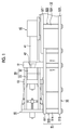
- Fig. 1 is a view illustrating an injection molding machine according to an embodiment of the invention.
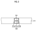
- Fig. 2 is a cross-sectional view along line II-II in Fig. 1 .
- the injection molding machine has a mold clamping unit 10, an injection unit 40, a frame 50, and the like.
- the mold clamping unit 10 performs mold closing, mold clamping, and mold opening of a mold unit 30.
- the mold unit 30 is configured to include a stationary mold 32 and a movable mold 33.
- the mold clamping unit 10 has a stationary platen 12 to which the stationary mold 32 is attached, and a movable platen 13 to which the movable mold 33 is attached.
- the mold clamping unit 10 moves the movable platen 13 forward and backward with respect to the stationary platen 12, thereby performing the mold closing, the mold clamping, and the mold opening of the mold unit 30.
- the injection unit 40 fills the inside of the mold unit 30 in a mold clamping state with a molding material.
- the injection unit 40 has a cylinder 41 that heats the molding material, and a nozzle 42 provided at the tip of the cylinder 41.
- the injection unit 40 fills the inside of the mold unit 30 with the molding material melted within the cylinder 41 via the nozzle 42.
- the molding material filled within the mold unit 30 is hardened, and a molding product is obtained.
- the molding product is pushed out from the mold unit 30 after mold opening, and is taken out from the injection molding machine.
- the frame 50 supports the mold clamping unit 10 and the injection unit 40.
- the frame 50 may have a mold clamping unit frame 51 and an injection unit frame 52.
- the mold clamping unit frame 51 supports the mold clamping unit 10.
- the injection unit frame 52 supports the injection unit 40.
- the mold clamping unit frame 51 has an upper horizontal beam 511, a lower horizontal beam 512, and a vertical beam 513.
- the mold clamping unit 10 is placed on the upper horizontal beam 511, and the lower horizontal beam 512 is installed on a floor.
- the vertical beam 513 is a pillar parallel to the upward-downward direction, and connects the upper horizontal beam 511 and the lower horizontal beam 512.
- a cover may be provided in the mold clamping unit frame 51.
- the mold clamping unit frame 51 has a vertical beam reinforcing member 514 joined to the vertical beam 513.
- the vertical beam reinforcing member 514 is formed in a plate shape, the shape thereof is not particularly limited. Joining is performed by welding, bolt connection, or the like. Accordingly, the rigidity of the mold clamping unit frame 51 can be improved, and the vibration at the time of the operation of the injection molding machine can be reduced.
- the vertical beam 513 in a crosswide sectional view of the vertical beam 513, the vertical beam 513, as illustrated in Fig. 2 , may be formed in an H shape, or may have two parallel parts 513a and 513b parallel to each other, and a perpendicular part 513c that connects the two parallel parts 513a and 513b.
- the perpendicular part 513c in the crosswise sectional view of the vertical beam 513, is made parallel to the longitudinal direction (the leftward-rightward direction in Fig. 2 ) of the upper horizontal beam 511, but may be made parallel to a width direction (the upward-downward direction in Fig. 2 ) of the upper horizontal beam 511.
- H-shaped steel or the like is used as the vertical beam 513.
- the H-shaped steel has excellent bending strength compared with other shape steels.
- the vertical beam reinforcing member 514 may be joined by two parallel parts 513a and 513b, or may be made parallel to the perpendicular part 513c. Although the vertical beam reinforcing member 514 may be provided on one side of the vertical beam 513, as illustrated in Fig. 2 , vertical beam reinforcing members may be provided on both sides of the vertical beam 513. As the vertical beam reinforcing members 514 are provided on both sides of the vertical beam 513, a structure in which a rectangular frame is supported by pillars from the inside can be formed.
- the rectangular frame is configured to include the two parallel parts 513a and 513b and the two vertical beam reinforcing members 514, and the pillar that supports the rectangular frame from inside is configured to include the perpendicular part 513c.
- the structure in which the rectangular frame is supported by the pillar from the inside can also be formed by inserting a vertical beam reinforcing member into an angular pipe-like vertical beam.
- the vertical beam reinforcing members 514 cover and conceal recesses formed by the two parallel parts 513a and 513b and the perpendicular part 513c in Fig. 1 , the vertical beam reinforcing members may not be covered and concealed.
- the vertical beam reinforcing members 514 are made oblique with respect to the longitudinal direction (upward-downward direction) of the vertical beam 513, and different height parts of two parallel parts 513a and 513b may be connected. Even in this case, the vertical beam reinforcing members 514 may be made parallel to the perpendicular part 513c, in the crosswise sectional view of the vertical beam 513.
- the vertical beam reinforcing members 514 may be connected to width-direction ends (upward-downward-direction ends in Fig. 2 ) of the upper horizontal beam 511 in a case where the vertical beam reinforcing members are parallel to the longitudinal direction of the upper horizontal beam 511.
- the vertical beam reinforcing members 514 are disposed on extension lines of side wall parts of the upper horizontal beam 511. Hence, deflection of the upper horizontal beam 511 caused by the load of the mold clamping unit 10 can be reduced.
- the vertical beam reinforcing members 514 may be connected to width-direction ends of the lower horizontal beam 512 in a case where the vertical beam reinforcing members are parallel to the longitudinal direction of the lower horizontal beam 512, in the crosswise sectional view of the vertical beam 513.
- the vertical beam reinforcing members 514 are disposed on extension lines of side wall parts of the lower horizontal beam 512. Hence, deflection of the lower horizontal beam 512 caused by the load of the mold clamping unit 10 can be reduced.
- the injection unit frame 52 has an upper horizontal beam 521, a lower horizontal beam 522, and a vertical beam 523.
- the injection unit 40 is placed on the upper horizontal beam 521, and the lower horizontal beam 522 is installed on a floor.
- the vertical beam 523 is a pillar parallel to the upward-downward direction, and connects the upper horizontal beam 521 and the lower horizontal beam 522.
- a cover may be provided in the
- the upper horizontal beam 521 of the injection unit frame 52 may be disposed at a different stage above the upper horizontal beam 511 of the mold clamping unit frame 51, or for example, may be placed on the upper horizontal beam 511 of the mold clamping unit frame 51.
- the upper horizontal beam 521 of the injection unit frame 52 of the present embodiment is disposed at a stage different from the upper horizontal beam 511 of the mold clamping unit frame 51, the upper horizontal beam may be disposed at the same height as the upper horizontal beam 511 of the mold clamping unit frame 51.
- the injection unit frame 52 and the mold clamping unit frame 51 may be integrally formed.
- the injection unit frame 52 has a vertical beam reinforcing member 524 joined to the vertical beam 523.
- the joining of the vertical beam reinforcing member 524 of the injection unit frame 52 is performed similar to the joining of the vertical beam reinforcing members 514 of the mold clamping unit frame 51. Accordingly, the rigidity of the injection unit frame 52 can be improved, and the vibration at the time of the operation of the injection molding machine can be reduced.
- the frame of the injection molding machine may have a reinforcing member joined to a beam in at least one of the mold clamping unit frame and the injection unit frame.
- the beam to which the reinforcing member is joined may be any one or both of a vertical beam and a horizontal beam.
- the beam to which the reinforcing member is joined may be formed in an H shape in the crosswise sectional view as described above.
- a reinforcing member joined to the horizontal beam may be connected to a width-direction end of the vertical beam, in a case where the horizontal beam reinforcing member is made parallel to the longitudinal direction of the vertical beam in a crosswise sectional view of the horizontal beam.
- the horizontal beam reinforcing member is disposed on an extension line of a side wall part of the vertical beam.
Landscapes
- Engineering & Computer Science (AREA)
- Manufacturing & Machinery (AREA)
- Mechanical Engineering (AREA)
- Injection Moulding Of Plastics Or The Like (AREA)
- Moulds For Moulding Plastics Or The Like (AREA)
Abstract
Description
- Priority is claimed to Japanese Patent Application No.
2015-073973, filed March 31, 2015 - The present invention relates to an injection molding machine.
- Injection molding machines have a mold clamping unit that performs mold closing, mold clamping, and mold opening of a mold unit, an injection unit that fills the inside of the mold unit with a molding material, and a frame that supports the mold clamping unit and the injection unit (for example, refer to Patent Japanese Unexamined Patent Application Publication No.
2000-185335 - A technique capable of reducing the vibration at the time of the operation of the injection molding machine has been desired.
- The invention has been made in view of the above problems, and a main object thereof is to provide an injection molding machine that can reduce the vibration at the time of the operation of the injection molding machine.
- In order to solve the above problems, according to an aspect of the invention, there is provided an injection molding machine including a mold clamping unit that performs mold closing, mold clamping, and mold opening of a mold unit; an injection unit that fills the interior of the mold unit with a molding material; and a frame that supports at least one of the mold clamping unit and the injection unit. The frame has a beam and a reinforcing member joined to the beam.
- According to the invention, the injection molding machine that can reduce the vibration at the time of the operation of the injection molding machine is provided.
-
-
Fig. 1 is a view illustrating an injection molding machine according to an embodiment of the invention. -
Fig. 2 is a cross-sectional view along line II-II inFig. 1 . - Hereinafter, an embodiment for carrying out the invention will be described with reference to the drawings. In the drawings, the same or corresponding components will be designated by the same or corresponding reference signs, and the description thereof will be omitted.
-
Fig. 1 is a view illustrating an injection molding machine according to an embodiment of the invention.Fig. 2 is a cross-sectional view along line II-II inFig. 1 . The injection molding machine has amold clamping unit 10, aninjection unit 40, aframe 50, and the like. - The
mold clamping unit 10 performs mold closing, mold clamping, and mold opening of amold unit 30. Themold unit 30 is configured to include astationary mold 32 and amovable mold 33. Themold clamping unit 10 has astationary platen 12 to which thestationary mold 32 is attached, and amovable platen 13 to which themovable mold 33 is attached. Themold clamping unit 10 moves themovable platen 13 forward and backward with respect to thestationary platen 12, thereby performing the mold closing, the mold clamping, and the mold opening of themold unit 30. - The
injection unit 40 fills the inside of themold unit 30 in a mold clamping state with a molding material. Theinjection unit 40 has acylinder 41 that heats the molding material, and anozzle 42 provided at the tip of thecylinder 41. Theinjection unit 40 fills the inside of themold unit 30 with the molding material melted within thecylinder 41 via thenozzle 42. The molding material filled within themold unit 30 is hardened, and a molding product is obtained. The molding product is pushed out from themold unit 30 after mold opening, and is taken out from the injection molding machine. - The
frame 50 supports themold clamping unit 10 and theinjection unit 40. Theframe 50 may have a moldclamping unit frame 51 and aninjection unit frame 52. The moldclamping unit frame 51 supports themold clamping unit 10. Theinjection unit frame 52 supports theinjection unit 40. - The mold
clamping unit frame 51 has an upperhorizontal beam 511, a lowerhorizontal beam 512, and avertical beam 513. Themold clamping unit 10 is placed on the upperhorizontal beam 511, and the lowerhorizontal beam 512 is installed on a floor. Thevertical beam 513 is a pillar parallel to the upward-downward direction, and connects the upperhorizontal beam 511 and the lowerhorizontal beam 512. A cover may be provided in the moldclamping unit frame 51. - The mold
clamping unit frame 51 has a verticalbeam reinforcing member 514 joined to thevertical beam 513. Although the verticalbeam reinforcing member 514 is formed in a plate shape, the shape thereof is not particularly limited. Joining is performed by welding, bolt connection, or the like. Accordingly, the rigidity of the moldclamping unit frame 51 can be improved, and the vibration at the time of the operation of the injection molding machine can be reduced. - In a crosswide sectional view of the
vertical beam 513, thevertical beam 513, as illustrated inFig. 2 , may be formed in an H shape, or may have twoparallel parts perpendicular part 513c that connects the twoparallel parts vertical beam 513, theperpendicular part 513c, as illustrated inFig. 2 , is made parallel to the longitudinal direction (the leftward-rightward direction inFig. 2 ) of the upperhorizontal beam 511, but may be made parallel to a width direction (the upward-downward direction inFig. 2 ) of the upperhorizontal beam 511. As thevertical beam 513, for example, H-shaped steel or the like is used. The H-shaped steel has excellent bending strength compared with other shape steels. - The vertical
beam reinforcing member 514 may be joined by twoparallel parts perpendicular part 513c. Although the verticalbeam reinforcing member 514 may be provided on one side of thevertical beam 513, as illustrated inFig. 2 , vertical beam reinforcing members may be provided on both sides of thevertical beam 513. As the verticalbeam reinforcing members 514 are provided on both sides of thevertical beam 513, a structure in which a rectangular frame is supported by pillars from the inside can be formed. The rectangular frame is configured to include the twoparallel parts beam reinforcing members 514, and the pillar that supports the rectangular frame from inside is configured to include theperpendicular part 513c. - In addition, the structure in which the rectangular frame is supported by the pillar from the inside can also be formed by inserting a vertical beam reinforcing member into an angular pipe-like vertical beam.
- Although the vertical
beam reinforcing members 514 cover and conceal recesses formed by the twoparallel parts perpendicular part 513c inFig. 1 , the vertical beam reinforcing members may not be covered and concealed. For example, the verticalbeam reinforcing members 514 are made oblique with respect to the longitudinal direction (upward-downward direction) of thevertical beam 513, and different height parts of twoparallel parts beam reinforcing members 514 may be made parallel to theperpendicular part 513c, in the crosswise sectional view of thevertical beam 513. - In the crosswise sectional view of the
vertical beam 513, the verticalbeam reinforcing members 514, as illustrated inFig. 2 , may be connected to width-direction ends (upward-downward-direction ends inFig. 2 ) of the upperhorizontal beam 511 in a case where the vertical beam reinforcing members are parallel to the longitudinal direction of the upperhorizontal beam 511. For example, in a case where the upperhorizontal beam 511 is formed in a rectangular shape in the crosswise sectional view of the upperhorizontal beam 511, the verticalbeam reinforcing members 514 are disposed on extension lines of side wall parts of the upperhorizontal beam 511. Hence, deflection of the upperhorizontal beam 511 caused by the load of themold clamping unit 10 can be reduced. - Similarly, the vertical
beam reinforcing members 514 may be connected to width-direction ends of the lowerhorizontal beam 512 in a case where the vertical beam reinforcing members are parallel to the longitudinal direction of the lowerhorizontal beam 512, in the crosswise sectional view of thevertical beam 513. For example, in a case where the lowerhorizontal beam 512 is formed in a rectangular shape in the crosswise sectional view of the lowerhorizontal beam 512, the verticalbeam reinforcing members 514 are disposed on extension lines of side wall parts of the lowerhorizontal beam 512. Hence, deflection of the lowerhorizontal beam 512 caused by the load of themold clamping unit 10 can be reduced. - The
injection unit frame 52 has an upperhorizontal beam 521, a lowerhorizontal beam 522, and avertical beam 523. Theinjection unit 40 is placed on the upperhorizontal beam 521, and the lowerhorizontal beam 522 is installed on a floor. Thevertical beam 523 is a pillar parallel to the upward-downward direction, and connects the upperhorizontal beam 521 and the lowerhorizontal beam 522. A cover may be provided in the - The upper
horizontal beam 521 of theinjection unit frame 52 may be disposed at a different stage above the upperhorizontal beam 511 of the moldclamping unit frame 51, or for example, may be placed on the upperhorizontal beam 511 of the moldclamping unit frame 51. - In addition, although the upper
horizontal beam 521 of theinjection unit frame 52 of the present embodiment is disposed at a stage different from the upperhorizontal beam 511 of the moldclamping unit frame 51, the upper horizontal beam may be disposed at the same height as the upperhorizontal beam 511 of the moldclamping unit frame 51. Theinjection unit frame 52 and the moldclamping unit frame 51 may be integrally formed. - The
injection unit frame 52 has a verticalbeam reinforcing member 524 joined to thevertical beam 523. The joining of the verticalbeam reinforcing member 524 of theinjection unit frame 52 is performed similar to the joining of the verticalbeam reinforcing members 514 of the moldclamping unit frame 51. Accordingly, the rigidity of theinjection unit frame 52 can be improved, and the vibration at the time of the operation of the injection molding machine can be reduced. - Although the embodiment of the injection molding machine has been described above, the invention is not limited to the above-described embodiment, and various alterations and improvements can be made within the scope of the invention described in the claims.
- For example, the frame of the injection molding machine may have a reinforcing member joined to a beam in at least one of the mold clamping unit frame and the injection unit frame. Additionally, the beam to which the reinforcing member is joined may be any one or both of a vertical beam and a horizontal beam. The beam to which the reinforcing member is joined may be formed in an H shape in the crosswise sectional view as described above.
- A reinforcing member joined to the horizontal beam may be connected to a width-direction end of the vertical beam, in a case where the horizontal beam reinforcing member is made parallel to the longitudinal direction of the vertical beam in a crosswise sectional view of the horizontal beam. For example, in a case where the vertical beam is formed in a rectangular shape in a crosswise sectional view of the vertical beam, the horizontal beam reinforcing member is disposed on an extension line of a side wall part of the vertical beam.
Claims (4)
- An injection molding machine comprising:a mold clamping unit that performs mold closing, mold clamping, and mold opening of a mold unit;an injection unit that fills the interior of the mold unit with a molding material; anda frame that supports at least one of the mold clamping unit and the injection unit,wherein the frame has a beam and a reinforcing member joined to the beam.
- The injection molding machine according to Claim 1,
wherein the beam is formed in an H shape in a crosswise sectional view of the beam, and has two parallel parts and a perpendicular part that connects the two parallel parts, and
wherein the reinforcing member is joined to the two parallel parts and is made parallel to the perpendicular part. - The injection molding machine according to Claim 1 or 2,
wherein the reinforcing member is joined to a vertical beam of the frame. - The injection molding machine according to any one of Claims 1 to 3,
wherein the reinforcing member is joined to a horizontal beam of the frame.
Applications Claiming Priority (1)
| Application Number | Priority Date | Filing Date | Title |
|---|---|---|---|
| JP2015073973A JP6558930B2 (en) | 2015-03-31 | 2015-03-31 | Injection molding machine |
Publications (2)
| Publication Number | Publication Date |
|---|---|
| EP3075515A1 true EP3075515A1 (en) | 2016-10-05 |
| EP3075515B1 EP3075515B1 (en) | 2018-09-26 |
Family
ID=55586228
Family Applications (1)
| Application Number | Title | Priority Date | Filing Date |
|---|---|---|---|
| EP16161146.2A Active EP3075515B1 (en) | 2015-03-31 | 2016-03-18 | Injection molding machine |
Country Status (3)
| Country | Link |
|---|---|
| EP (1) | EP3075515B1 (en) |
| JP (1) | JP6558930B2 (en) |
| CN (1) | CN106003543A (en) |
Citations (6)
| Publication number | Priority date | Publication date | Assignee | Title |
|---|---|---|---|---|
| GB1209990A (en) * | 1967-09-30 | 1970-10-28 | Stefan Fischer | Improvements in apparatus for blow-moulding hollow articles |
| DE2441805A1 (en) * | 1974-08-31 | 1976-03-11 | Krauss Maffei Ag | Injection moulding machine for plastics - where moving die-plate is mounted on trunnions to provide a limited amt. of float |
| JP2000185335A (en) | 1998-12-21 | 2000-07-04 | Niigata Eng Co Ltd | Injection molding machine |
| JP2004148426A (en) * | 2002-10-30 | 2004-05-27 | Toshiba Mach Co Ltd | Double column machine tool |
| CN203357751U (en) * | 2013-07-18 | 2013-12-25 | 无锡锦和科技有限公司 | Cross beam for vulcanizing machine |
| WO2014046132A1 (en) * | 2012-09-21 | 2014-03-27 | 東洋機械金属株式会社 | Molding machine |
Family Cites Families (8)
| Publication number | Priority date | Publication date | Assignee | Title |
|---|---|---|---|---|
| JPS5537369B2 (en) * | 1975-01-31 | 1980-09-27 | ||
| JPH0651974B2 (en) * | 1987-09-29 | 1994-07-06 | 丸藤シートパイル株式会社 | Boarding slope of work gantry and its construction method |
| JPH0742234A (en) * | 1993-07-28 | 1995-02-10 | Taisei Corp | Compression brace end fitting structure |
| JP3631906B2 (en) * | 1998-09-16 | 2005-03-23 | 東洋機械金属株式会社 | High rigidity frame of injection molding machine |
| JP4746023B2 (en) * | 2007-11-12 | 2011-08-10 | 三菱重工業株式会社 | Seismic retrofit method for steel structures and seismic steel structures |
| CN101839074B (en) * | 2010-06-22 | 2011-07-27 | 中国建筑第二工程局有限公司 | Steel frame reinforcing column and reinforcing method thereof |
| DE102010048658A1 (en) * | 2010-10-15 | 2012-04-19 | Otto Männer Innovation GmbH | Machine table for an injection molding machine, comprises a base frame arranged on a base plate that is arranged on support elements fixed on the frame and comprises a tempering element, where the frame comprises lower and upper frames |
| JP5580177B2 (en) * | 2010-11-26 | 2014-08-27 | ファナック株式会社 | Injection molding machine equipped with a tiltable grease receiver |
-
2015
- 2015-03-31 JP JP2015073973A patent/JP6558930B2/en active Active
-
2016
- 2016-03-01 CN CN201610114739.4A patent/CN106003543A/en active Pending
- 2016-03-18 EP EP16161146.2A patent/EP3075515B1/en active Active
Patent Citations (6)
| Publication number | Priority date | Publication date | Assignee | Title |
|---|---|---|---|---|
| GB1209990A (en) * | 1967-09-30 | 1970-10-28 | Stefan Fischer | Improvements in apparatus for blow-moulding hollow articles |
| DE2441805A1 (en) * | 1974-08-31 | 1976-03-11 | Krauss Maffei Ag | Injection moulding machine for plastics - where moving die-plate is mounted on trunnions to provide a limited amt. of float |
| JP2000185335A (en) | 1998-12-21 | 2000-07-04 | Niigata Eng Co Ltd | Injection molding machine |
| JP2004148426A (en) * | 2002-10-30 | 2004-05-27 | Toshiba Mach Co Ltd | Double column machine tool |
| WO2014046132A1 (en) * | 2012-09-21 | 2014-03-27 | 東洋機械金属株式会社 | Molding machine |
| CN203357751U (en) * | 2013-07-18 | 2013-12-25 | 无锡锦和科技有限公司 | Cross beam for vulcanizing machine |
Also Published As
| Publication number | Publication date |
|---|---|
| JP2016193519A (en) | 2016-11-17 |
| EP3075515B1 (en) | 2018-09-26 |
| JP6558930B2 (en) | 2019-08-14 |
| CN106003543A (en) | 2016-10-12 |
Similar Documents
| Publication | Publication Date | Title |
|---|---|---|
| US10773574B2 (en) | Carrier device for a motor vehicle | |
| EP3050781A1 (en) | Vehicle body reinforcement structure | |
| US9352388B2 (en) | Integration of one piece door inner panel with impact beam | |
| JP6013110B2 (en) | Molding machine | |
| US9669877B2 (en) | Vehicle body framework structure and method of manufacturing the same | |
| CN111037176A (en) | Welding manipulator and welding processing equipment for reinforcement cage | |
| US20190047139A1 (en) | Support rail for a robot platform that is displaceable in a translatory manner, and displacement system and robot system having such a support rail | |
| EP3075515B1 (en) | Injection molding machine | |
| JPWO2010146690A1 (en) | Vehicle structure | |
| CN101544234B (en) | Platform door device | |
| CN109328158B (en) | Structure for the front end of a motor vehicle | |
| CN104005171A (en) | Plastic looping tool guide bar | |
| JP2016209921A (en) | Mold equipment | |
| MY202178A (en) | Vehicle structure comprising a front pillar reinforcement part and a side rail | |
| CN101903155B (en) | Injection molding machine with protective liner | |
| EP3075514B1 (en) | Injection molding machine | |
| JP6289983B2 (en) | Clamping device for hollow molding machine | |
| CN107020718A (en) | The installation stand and injection molding device for molding of injection device | |
| KR101294160B1 (en) | Forming Apparatus for Reinforcement Member with closed section and Manufacturing Method of Reinforcement Member using the Forming Apparatus | |
| EP3075513B1 (en) | Injection molding machine | |
| US9616648B2 (en) | Profile carriers and related methods | |
| CN105415618A (en) | Injection Molding Machine | |
| JP3205448U (en) | Mold take-out machine | |
| JP7733163B2 (en) | molding machine | |
| JP7801846B2 (en) | Molded product removal machine |
Legal Events
| Date | Code | Title | Description |
|---|---|---|---|
| PUAI | Public reference made under article 153(3) epc to a published international application that has entered the european phase |
Free format text: ORIGINAL CODE: 0009012 |
|
| 17P | Request for examination filed |
Effective date: 20160318 |
|
| AK | Designated contracting states |
Kind code of ref document: A1 Designated state(s): AL AT BE BG CH CY CZ DE DK EE ES FI FR GB GR HR HU IE IS IT LI LT LU LV MC MK MT NL NO PL PT RO RS SE SI SK SM TR |
|
| AX | Request for extension of the european patent |
Extension state: BA ME |
|
| STAA | Information on the status of an ep patent application or granted ep patent |
Free format text: STATUS: EXAMINATION IS IN PROGRESS |
|
| GRAP | Despatch of communication of intention to grant a patent |
Free format text: ORIGINAL CODE: EPIDOSNIGR1 |
|
| STAA | Information on the status of an ep patent application or granted ep patent |
Free format text: STATUS: GRANT OF PATENT IS INTENDED |
|
| INTG | Intention to grant announced |
Effective date: 20180425 |
|
| RIN1 | Information on inventor provided before grant (corrected) |
Inventor name: YAMANAKA, KAZUMA Inventor name: MITAMA, ICHIRO Inventor name: KIKUCHI, TOMOKI |
|
| GRAS | Grant fee paid |
Free format text: ORIGINAL CODE: EPIDOSNIGR3 |
|
| GRAA | (expected) grant |
Free format text: ORIGINAL CODE: 0009210 |
|
| STAA | Information on the status of an ep patent application or granted ep patent |
Free format text: STATUS: THE PATENT HAS BEEN GRANTED |
|
| AK | Designated contracting states |
Kind code of ref document: B1 Designated state(s): AL AT BE BG CH CY CZ DE DK EE ES FI FR GB GR HR HU IE IS IT LI LT LU LV MC MK MT NL NO PL PT RO RS SE SI SK SM TR |
|
| REG | Reference to a national code |
Ref country code: GB Ref legal event code: FG4D |
|
| REG | Reference to a national code |
Ref country code: CH Ref legal event code: EP |
|
| REG | Reference to a national code |
Ref country code: AT Ref legal event code: REF Ref document number: 1045475 Country of ref document: AT Kind code of ref document: T Effective date: 20181015 |
|
| REG | Reference to a national code |
Ref country code: IE Ref legal event code: FG4D |
|
| REG | Reference to a national code |
Ref country code: DE Ref legal event code: R096 Ref document number: 602016005849 Country of ref document: DE |
|
| REG | Reference to a national code |
Ref country code: CH Ref legal event code: NV Representative=s name: SCHNEIDER FELDMANN AG PATENT- UND MARKENANWAEL, CH |
|
| REG | Reference to a national code |
Ref country code: NL Ref legal event code: MP Effective date: 20180926 |
|
| PG25 | Lapsed in a contracting state [announced via postgrant information from national office to epo] |
Ref country code: LT Free format text: LAPSE BECAUSE OF FAILURE TO SUBMIT A TRANSLATION OF THE DESCRIPTION OR TO PAY THE FEE WITHIN THE PRESCRIBED TIME-LIMIT Effective date: 20180926 Ref country code: GR Free format text: LAPSE BECAUSE OF FAILURE TO SUBMIT A TRANSLATION OF THE DESCRIPTION OR TO PAY THE FEE WITHIN THE PRESCRIBED TIME-LIMIT Effective date: 20181227 Ref country code: NO Free format text: LAPSE BECAUSE OF FAILURE TO SUBMIT A TRANSLATION OF THE DESCRIPTION OR TO PAY THE FEE WITHIN THE PRESCRIBED TIME-LIMIT Effective date: 20181226 Ref country code: SE Free format text: LAPSE BECAUSE OF FAILURE TO SUBMIT A TRANSLATION OF THE DESCRIPTION OR TO PAY THE FEE WITHIN THE PRESCRIBED TIME-LIMIT Effective date: 20180926 Ref country code: BG Free format text: LAPSE BECAUSE OF FAILURE TO SUBMIT A TRANSLATION OF THE DESCRIPTION OR TO PAY THE FEE WITHIN THE PRESCRIBED TIME-LIMIT Effective date: 20181226 Ref country code: FI Free format text: LAPSE BECAUSE OF FAILURE TO SUBMIT A TRANSLATION OF THE DESCRIPTION OR TO PAY THE FEE WITHIN THE PRESCRIBED TIME-LIMIT Effective date: 20180926 Ref country code: RS Free format text: LAPSE BECAUSE OF FAILURE TO SUBMIT A TRANSLATION OF THE DESCRIPTION OR TO PAY THE FEE WITHIN THE PRESCRIBED TIME-LIMIT Effective date: 20180926 |
|
| REG | Reference to a national code |
Ref country code: LT Ref legal event code: MG4D |
|
| PG25 | Lapsed in a contracting state [announced via postgrant information from national office to epo] |
Ref country code: HR Free format text: LAPSE BECAUSE OF FAILURE TO SUBMIT A TRANSLATION OF THE DESCRIPTION OR TO PAY THE FEE WITHIN THE PRESCRIBED TIME-LIMIT Effective date: 20180926 Ref country code: AL Free format text: LAPSE BECAUSE OF FAILURE TO SUBMIT A TRANSLATION OF THE DESCRIPTION OR TO PAY THE FEE WITHIN THE PRESCRIBED TIME-LIMIT Effective date: 20180926 Ref country code: LV Free format text: LAPSE BECAUSE OF FAILURE TO SUBMIT A TRANSLATION OF THE DESCRIPTION OR TO PAY THE FEE WITHIN THE PRESCRIBED TIME-LIMIT Effective date: 20180926 |
|
| PG25 | Lapsed in a contracting state [announced via postgrant information from national office to epo] |
Ref country code: ES Free format text: LAPSE BECAUSE OF FAILURE TO SUBMIT A TRANSLATION OF THE DESCRIPTION OR TO PAY THE FEE WITHIN THE PRESCRIBED TIME-LIMIT Effective date: 20180926 Ref country code: IT Free format text: LAPSE BECAUSE OF FAILURE TO SUBMIT A TRANSLATION OF THE DESCRIPTION OR TO PAY THE FEE WITHIN THE PRESCRIBED TIME-LIMIT Effective date: 20180926 Ref country code: EE Free format text: LAPSE BECAUSE OF FAILURE TO SUBMIT A TRANSLATION OF THE DESCRIPTION OR TO PAY THE FEE WITHIN THE PRESCRIBED TIME-LIMIT Effective date: 20180926 Ref country code: NL Free format text: LAPSE BECAUSE OF FAILURE TO SUBMIT A TRANSLATION OF THE DESCRIPTION OR TO PAY THE FEE WITHIN THE PRESCRIBED TIME-LIMIT Effective date: 20180926 Ref country code: RO Free format text: LAPSE BECAUSE OF FAILURE TO SUBMIT A TRANSLATION OF THE DESCRIPTION OR TO PAY THE FEE WITHIN THE PRESCRIBED TIME-LIMIT Effective date: 20180926 Ref country code: CZ Free format text: LAPSE BECAUSE OF FAILURE TO SUBMIT A TRANSLATION OF THE DESCRIPTION OR TO PAY THE FEE WITHIN THE PRESCRIBED TIME-LIMIT Effective date: 20180926 Ref country code: IS Free format text: LAPSE BECAUSE OF FAILURE TO SUBMIT A TRANSLATION OF THE DESCRIPTION OR TO PAY THE FEE WITHIN THE PRESCRIBED TIME-LIMIT Effective date: 20190126 Ref country code: PL Free format text: LAPSE BECAUSE OF FAILURE TO SUBMIT A TRANSLATION OF THE DESCRIPTION OR TO PAY THE FEE WITHIN THE PRESCRIBED TIME-LIMIT Effective date: 20180926 |
|
| PG25 | Lapsed in a contracting state [announced via postgrant information from national office to epo] |
Ref country code: PT Free format text: LAPSE BECAUSE OF FAILURE TO SUBMIT A TRANSLATION OF THE DESCRIPTION OR TO PAY THE FEE WITHIN THE PRESCRIBED TIME-LIMIT Effective date: 20190126 Ref country code: SK Free format text: LAPSE BECAUSE OF FAILURE TO SUBMIT A TRANSLATION OF THE DESCRIPTION OR TO PAY THE FEE WITHIN THE PRESCRIBED TIME-LIMIT Effective date: 20180926 Ref country code: SM Free format text: LAPSE BECAUSE OF FAILURE TO SUBMIT A TRANSLATION OF THE DESCRIPTION OR TO PAY THE FEE WITHIN THE PRESCRIBED TIME-LIMIT Effective date: 20180926 |
|
| REG | Reference to a national code |
Ref country code: DE Ref legal event code: R097 Ref document number: 602016005849 Country of ref document: DE |
|
| PG25 | Lapsed in a contracting state [announced via postgrant information from national office to epo] |
Ref country code: DK Free format text: LAPSE BECAUSE OF FAILURE TO SUBMIT A TRANSLATION OF THE DESCRIPTION OR TO PAY THE FEE WITHIN THE PRESCRIBED TIME-LIMIT Effective date: 20180926 |
|
| PLBE | No opposition filed within time limit |
Free format text: ORIGINAL CODE: 0009261 |
|
| STAA | Information on the status of an ep patent application or granted ep patent |
Free format text: STATUS: NO OPPOSITION FILED WITHIN TIME LIMIT |
|
| 26N | No opposition filed |
Effective date: 20190627 |
|
| PG25 | Lapsed in a contracting state [announced via postgrant information from national office to epo] |
Ref country code: SI Free format text: LAPSE BECAUSE OF FAILURE TO SUBMIT A TRANSLATION OF THE DESCRIPTION OR TO PAY THE FEE WITHIN THE PRESCRIBED TIME-LIMIT Effective date: 20180926 Ref country code: MC Free format text: LAPSE BECAUSE OF FAILURE TO SUBMIT A TRANSLATION OF THE DESCRIPTION OR TO PAY THE FEE WITHIN THE PRESCRIBED TIME-LIMIT Effective date: 20180926 |
|
| PG25 | Lapsed in a contracting state [announced via postgrant information from national office to epo] |
Ref country code: LU Free format text: LAPSE BECAUSE OF NON-PAYMENT OF DUE FEES Effective date: 20190318 |
|
| REG | Reference to a national code |
Ref country code: BE Ref legal event code: MM Effective date: 20190331 |
|
| PG25 | Lapsed in a contracting state [announced via postgrant information from national office to epo] |
Ref country code: IE Free format text: LAPSE BECAUSE OF NON-PAYMENT OF DUE FEES Effective date: 20190318 |
|
| PG25 | Lapsed in a contracting state [announced via postgrant information from national office to epo] |
Ref country code: BE Free format text: LAPSE BECAUSE OF NON-PAYMENT OF DUE FEES Effective date: 20190331 Ref country code: FR Free format text: LAPSE BECAUSE OF NON-PAYMENT OF DUE FEES Effective date: 20190331 |
|
| PG25 | Lapsed in a contracting state [announced via postgrant information from national office to epo] |
Ref country code: TR Free format text: LAPSE BECAUSE OF FAILURE TO SUBMIT A TRANSLATION OF THE DESCRIPTION OR TO PAY THE FEE WITHIN THE PRESCRIBED TIME-LIMIT Effective date: 20180926 |
|
| PG25 | Lapsed in a contracting state [announced via postgrant information from national office to epo] |
Ref country code: MT Free format text: LAPSE BECAUSE OF NON-PAYMENT OF DUE FEES Effective date: 20190318 |
|
| REG | Reference to a national code |
Ref country code: CH Ref legal event code: PFA Owner name: SUMITOMO HEAVY INDUSTRIES, LTD., JP Free format text: FORMER OWNER: SUMITOMO HEAVY INDUSTRIES, LTD., JP |
|
| GBPC | Gb: european patent ceased through non-payment of renewal fee |
Effective date: 20200318 |
|
| PG25 | Lapsed in a contracting state [announced via postgrant information from national office to epo] |
Ref country code: GB Free format text: LAPSE BECAUSE OF NON-PAYMENT OF DUE FEES Effective date: 20200318 |
|
| PG25 | Lapsed in a contracting state [announced via postgrant information from national office to epo] |
Ref country code: CY Free format text: LAPSE BECAUSE OF FAILURE TO SUBMIT A TRANSLATION OF THE DESCRIPTION OR TO PAY THE FEE WITHIN THE PRESCRIBED TIME-LIMIT Effective date: 20180926 |
|
| REG | Reference to a national code |
Ref country code: AT Ref legal event code: UEP Ref document number: 1045475 Country of ref document: AT Kind code of ref document: T Effective date: 20180926 |
|
| PG25 | Lapsed in a contracting state [announced via postgrant information from national office to epo] |
Ref country code: HU Free format text: LAPSE BECAUSE OF FAILURE TO SUBMIT A TRANSLATION OF THE DESCRIPTION OR TO PAY THE FEE WITHIN THE PRESCRIBED TIME-LIMIT; INVALID AB INITIO Effective date: 20160318 |
|
| PGFP | Annual fee paid to national office [announced via postgrant information from national office to epo] |
Ref country code: CH Payment date: 20220215 Year of fee payment: 7 Ref country code: AT Payment date: 20220225 Year of fee payment: 7 |
|
| PG25 | Lapsed in a contracting state [announced via postgrant information from national office to epo] |
Ref country code: MK Free format text: LAPSE BECAUSE OF FAILURE TO SUBMIT A TRANSLATION OF THE DESCRIPTION OR TO PAY THE FEE WITHIN THE PRESCRIBED TIME-LIMIT Effective date: 20180926 |
|
| REG | Reference to a national code |
Ref country code: CH Ref legal event code: PL |
|
| REG | Reference to a national code |
Ref country code: AT Ref legal event code: MM01 Ref document number: 1045475 Country of ref document: AT Kind code of ref document: T Effective date: 20230318 |
|
| PG25 | Lapsed in a contracting state [announced via postgrant information from national office to epo] |
Ref country code: LI Free format text: LAPSE BECAUSE OF NON-PAYMENT OF DUE FEES Effective date: 20230331 Ref country code: CH Free format text: LAPSE BECAUSE OF NON-PAYMENT OF DUE FEES Effective date: 20230331 Ref country code: AT Free format text: LAPSE BECAUSE OF NON-PAYMENT OF DUE FEES Effective date: 20230318 |
|
| PGFP | Annual fee paid to national office [announced via postgrant information from national office to epo] |
Ref country code: DE Payment date: 20260128 Year of fee payment: 11 |