EP3075498A1 - Razor - Google Patents
Razor Download PDFInfo
- Publication number
- EP3075498A1 EP3075498A1 EP14865095.5A EP14865095A EP3075498A1 EP 3075498 A1 EP3075498 A1 EP 3075498A1 EP 14865095 A EP14865095 A EP 14865095A EP 3075498 A1 EP3075498 A1 EP 3075498A1
- Authority
- EP
- European Patent Office
- Prior art keywords
- blade
- blades
- portions
- plate
- reinforcement
- Prior art date
- Legal status (The legal status is an assumption and is not a legal conclusion. Google has not performed a legal analysis and makes no representation as to the accuracy of the status listed.)
- Granted
Links
- 230000002787 reinforcement Effects 0.000 claims abstract description 83
- 238000005520 cutting process Methods 0.000 claims abstract description 45
- 230000008878 coupling Effects 0.000 claims abstract description 41
- 238000010168 coupling process Methods 0.000 claims abstract description 41
- 238000005859 coupling reaction Methods 0.000 claims abstract description 41
- 238000003825 pressing Methods 0.000 claims description 19
- 238000005452 bending Methods 0.000 description 11
- 238000003466 welding Methods 0.000 description 10
- 238000000034 method Methods 0.000 description 8
- 230000002093 peripheral effect Effects 0.000 description 5
- 229910052751 metal Inorganic materials 0.000 description 4
- 239000002184 metal Substances 0.000 description 4
- XLYOFNOQVPJJNP-UHFFFAOYSA-N water Substances O XLYOFNOQVPJJNP-UHFFFAOYSA-N 0.000 description 4
- 230000008859 change Effects 0.000 description 3
- 239000000725 suspension Substances 0.000 description 3
- 230000002411 adverse Effects 0.000 description 2
- 229910052782 aluminium Inorganic materials 0.000 description 2
- XAGFODPZIPBFFR-UHFFFAOYSA-N aluminium Chemical compound [Al] XAGFODPZIPBFFR-UHFFFAOYSA-N 0.000 description 2
- 229910000963 austenitic stainless steel Inorganic materials 0.000 description 2
- 238000003780 insertion Methods 0.000 description 2
- 230000037431 insertion Effects 0.000 description 2
- 239000000463 material Substances 0.000 description 2
- 239000000853 adhesive Substances 0.000 description 1
- 230000001070 adhesive effect Effects 0.000 description 1
- 238000013459 approach Methods 0.000 description 1
- 230000015572 biosynthetic process Effects 0.000 description 1
- 230000007423 decrease Effects 0.000 description 1
- 230000005489 elastic deformation Effects 0.000 description 1
- 230000003370 grooming effect Effects 0.000 description 1
- 238000001746 injection moulding Methods 0.000 description 1
- 230000002452 interceptive effect Effects 0.000 description 1
- 238000004519 manufacturing process Methods 0.000 description 1
- 229910001105 martensitic stainless steel Inorganic materials 0.000 description 1
- 238000002844 melting Methods 0.000 description 1
- 230000008018 melting Effects 0.000 description 1
- 230000004048 modification Effects 0.000 description 1
- 238000012986 modification Methods 0.000 description 1
- 230000008569 process Effects 0.000 description 1
- 230000000452 restraining effect Effects 0.000 description 1
- 229910001220 stainless steel Inorganic materials 0.000 description 1
- 239000010935 stainless steel Substances 0.000 description 1
Images


Classifications
-
- B—PERFORMING OPERATIONS; TRANSPORTING
- B26—HAND CUTTING TOOLS; CUTTING; SEVERING
- B26B—HAND-HELD CUTTING TOOLS NOT OTHERWISE PROVIDED FOR
- B26B21/00—Razors of the open or knife type; Safety razors or other shaving implements of the planing type; Hair-trimming devices involving a razor-blade; Equipment therefor
- B26B21/40—Details or accessories
- B26B21/52—Handles, e.g. tiltable, flexible
- B26B21/521—Connection details, e.g. connection to razor heads
-
- B—PERFORMING OPERATIONS; TRANSPORTING
- B26—HAND CUTTING TOOLS; CUTTING; SEVERING
- B26B—HAND-HELD CUTTING TOOLS NOT OTHERWISE PROVIDED FOR
- B26B21/00—Razors of the open or knife type; Safety razors or other shaving implements of the planing type; Hair-trimming devices involving a razor-blade; Equipment therefor
- B26B21/08—Razors of the open or knife type; Safety razors or other shaving implements of the planing type; Hair-trimming devices involving a razor-blade; Equipment therefor involving changeable blades
- B26B21/14—Safety razors with one or more blades arranged transversely to the handle
- B26B21/22—Safety razors with one or more blades arranged transversely to the handle involving several blades to be used simultaneously
- B26B21/222—Safety razors with one or more blades arranged transversely to the handle involving several blades to be used simultaneously with the blades moulded into, or attached to, a changeable unit
- B26B21/225—Safety razors with one or more blades arranged transversely to the handle involving several blades to be used simultaneously with the blades moulded into, or attached to, a changeable unit the changeable unit being resiliently mounted on the handle
-
- B—PERFORMING OPERATIONS; TRANSPORTING
- B26—HAND CUTTING TOOLS; CUTTING; SEVERING
- B26B—HAND-HELD CUTTING TOOLS NOT OTHERWISE PROVIDED FOR
- B26B21/00—Razors of the open or knife type; Safety razors or other shaving implements of the planing type; Hair-trimming devices involving a razor-blade; Equipment therefor
- B26B21/08—Razors of the open or knife type; Safety razors or other shaving implements of the planing type; Hair-trimming devices involving a razor-blade; Equipment therefor involving changeable blades
- B26B21/14—Safety razors with one or more blades arranged transversely to the handle
- B26B21/22—Safety razors with one or more blades arranged transversely to the handle involving several blades to be used simultaneously
- B26B21/222—Safety razors with one or more blades arranged transversely to the handle involving several blades to be used simultaneously with the blades moulded into, or attached to, a changeable unit
- B26B21/227—Safety razors with one or more blades arranged transversely to the handle involving several blades to be used simultaneously with the blades moulded into, or attached to, a changeable unit with blades being resiliently mounted in the changeable unit
-
- B—PERFORMING OPERATIONS; TRANSPORTING
- B26—HAND CUTTING TOOLS; CUTTING; SEVERING
- B26B—HAND-HELD CUTTING TOOLS NOT OTHERWISE PROVIDED FOR
- B26B21/00—Razors of the open or knife type; Safety razors or other shaving implements of the planing type; Hair-trimming devices involving a razor-blade; Equipment therefor
- B26B21/40—Details or accessories
- B26B21/4012—Housing details, e.g. for cartridges
Definitions
- the present invention relates to a razor supporting a blade in a razor head.
- a razor head of a razor disclosed in Patent Document 1 includes a blade member to which blades are attached, a blade base member located on the back side of the razor head, and a top member located on the near side of the razor head. The blade member is clamped between the blade base member and the top member.
- the blade member includes blades and a seat on which the blades are arranged.
- the seat includes a blade supporting portion that supports the blades and a plurality of elastic leg portions that supports the blade supporting portion.
- the elastic leg portions are arranged in the blade base member.
- a plurality of blade mounting portions, a plurality of bridge portions, and a plurality of shaving scum removal holes are formed in the blade supporting portion.
- the blade mounting portions each extend in the extending direction of the cutting edge of the corresponding blade and are arranged in the blade arrangement direction, which is perpendicular to the extending direction of the cutting edge.
- the bridge portions extend in the blade arrangement direction to couple the blade mounting portions together.
- the shaving scum removal holes are arranged one by one for each of the blade mounting portions and extend in the extending direction of the cutting edge of the corresponding blade in correspondence with the cutting edge.
- Patent Document 1 Japanese Laid-Open Patent Publication No. 2007-215590
- the pressing force applied to the blades tend to deform the blade supporting portion. This may cause movement of the blades on the blade mounting portions relative to one another and change the relative positions of the blades, thus adversely affecting shaving comfort of the razor.
- the blade supporting portion also tends to be deformed by the heat generated when the blades are attached to the blade mounting portions through spot welding or the like. This may change the relative positions of the blade mounting portions at the time of welding the blades and also change the relative positions of the blades, thus adversely affecting the shaving comfort of the razor.
- the thickness of the blade supporting portion may be increased to improve the rigidity. This, however, would hamper bending of the blade supporting portion or welding of the blades to the blade mounting portions and is thus not preferable.
- a razor that includes a blade member including blades and a blade supporting portion, a blade base member arranged on a back side of the blade member, and a top member arranged on a near side of the blade member to hold the blade member between the top member and the blade base member with the blades of the blade member exposed to the exterior.
- the blade supporting portion includes a plurality of blade mounting portions arranged in a direction in which the blades are arranged, a reinforcement portion that improves rigidity of the blade mounting portions, and a coupling portion that couples the blade mounting portions together.
- the reinforcement portion is arranged in the blade mounting portions. As a result, even if the thickness of the blade supporting portion is increased to such an extent that bending of the blade supporting portion or welding of the blades to the blade mounting portions is facilitated, the rigidity of the blade mounting portions can be set high. This restrains deformation of the blade supporting portion.
- the reinforcement portion is preferably formed by being bent from the blade mounting portions.
- the reinforcement portion is bent from the blade mounting portions and thus formed easily.
- the reinforcement portion is preferably arranged between the blade mounting portions and the blade base member by being bent from the blade mounting portions toward the blade base member.
- the reinforcement portion is bent from the blade mounting portions and thus formed easily. Also, by arranging the reinforcement portion between the blade mounting portions and the blade base member, the reinforcement portion is arranged at such a position that the reinforcement portion does not interfere with the use of the razor.
- the reinforcement portion is preferably arranged between the blade mounting portions and the blade base member.
- the reinforcement portion is arranged at such a position that the reinforcement portion does not interfere with the use of the razor.
- the blade mounting portions preferably extend in an extending direction of the blades.
- the reinforcement portion is preferably one of a plurality of reinforcement portions that is arranged one by one for each of the blade mounting portions.
- the reinforcement portions which are arranged one by one for each of the blade mounting portions, improve the rigidity of the blade supporting portion, which has the multiple blades, as a whole.
- the blade mounting portions and the reinforcement portion are preferably formed integrally with one another.
- This configuration facilitates the forming of the blade mounting portions and the reinforcement portions.
- the blade supporting portion be formed as an integral body.
- This configuration facilitates the forming of the blade supporting portion.
- the coupling portion preferably extends in an arrangement direction of the blades to couple the blade mounting portions together.
- bridge portions improve the rigidity of the blade mounting portions.
- the blade supporting portion preferably has shaving scum removal holes, which are located on both sides of the coupling portion and arranged in the extending direction of the blade supporting portion.
- the removal holes preferably extend in an extending direction of cutting edges of the blades in correspondence with the cutting edges of the blades.
- Each of the reinforcement portions is preferably bent toward the blade base member from one of two sides of the corresponding blade mounting portion in a blade arrangement direction, the one side being opposite from the cutting edge of the associated blade.
- the reinforcement portions are formed easily.
- the reinforcement portions preferably extend in the extending direction of the cutting edge of each blade in correspondence with the shaving scum removal holes.
- the reinforcement portions which are arranged one by one for each of the shaving scum removal holes, improves the rigidity of the blade supporting portion as a whole regardless of formation of the shaving scum removal holes.
- a seat arranged in the blade member preferably has a mounting base that is formed integrally with the seat and supported by the blade base member.
- the mounting base allows stable arrangement of the seat of the blade member between the blade base member and the top member.
- An elastic portion is preferably arranged between the mounting base of the seat and the blade base member to allow the blade member to move integrally in correspondence with pressing force applied to the blades of the blade member when the blades contact a skin surface.
- the mounting base of the seat preferably has an elastic leg portion that is supported by the blade base member to allow the blade member to move integrally in correspondence with pressing force applied to the blades of the blade member when the blades contact a skin surface.
- the blade base member preferably has an elastic portion that supports the blade member to allow the blade member to move integrally in correspondence with pressing force applied to the blades of the blade member when the blades contact a skin surface.
- the elastic portion (an elastic leg portion or an elastic portion) ensures elastic movement of the blade member and decreases resistance to shaving.
- a cartridge razor according to a first embodiment will now be described with reference to Figs. 1 to 8 .
- a blade cartridge 11 is detachably attached to a holder 1.
- the direction in which the blade cartridge 11 approaches or separates from the skin when the razor is in use is defined as an x-axis
- the direction in which the cutting edge of the blade cartridge 11 extends is defined as a Y-axis
- the direction in which the holder 1 extends is defined as a z-axis.
- the x-axis, the y-axis, and the z-axis are perpendicular to one another.
- the side close to the user is defined as a front side or a near side and the side separate from the user is defined as a rear side or a back side.
- the holder 1 includes a grip portion 2 gripped by the user and a head portion 3 arranged at an upper end of the grip portion 2.
- an annular supporting portion 4 is formed in the head portion 3.
- a tubular receiving portion 5 is arranged inside the supporting portion 4 through an elastic plate 6.
- the receiving portion 5 is formed at a core position of the supporting portion 4 to project toward the front side along the x-axis.
- a coupling hole 7, which extends along the x-axis, is formed in the receiving portion 5.
- the coupling hole 7 includes an attachment/detachment port 8, which opens forward, and a manipulation port 9, which opens rearward. As illustrated in Fig.
- the coupling hole 7 includes an upper surface 7a and a lower surface 7b facing each other along the z-axis and a left surface 7c and a right surface 7d facing each other along the y-axis.
- the upper surface 7a and the lower surface 7b are set substantially parallel to each other.
- the distance between the left surface 7c and the right surface 7d is set to become greater from the lower surface 7b toward the upper surface 7a.
- Restriction grooves 10, each of which extends along the x-axis, are formed in the left surface 7c and the right surface 7d of the coupling hole 7.
- the blade cartridge 11 (the razor head) has a blade assembly 12 and a coupling projection 14.
- the blade assembly 12 includes a plurality of (four) blades 13, which are located on the near side of the blade assembly 12 and comes into contact with the skin.
- the coupling projection 14 is coupled to the back side of the blade assembly 12 and extends in a direction separating from the blades 13, or, in other words, rearward.
- the blade assembly 12 includes a blade member 15, a blade base member 16, and a top member 17.
- the coupling projection 14 is coupled to the rear surface of the blade base member 16.
- the top member 17 is formed in a rectangular frame shape.
- the blade member 15 is held between the blade base member 16 and the top member 17 by being held between the blade base member 16 and the top member 17. Specific configuration of the blade assembly 12 will be described later.
- the coupling projection 14 of the blade cartridge 11 has a guide portion 18, a cantilevered elastic portion 19, and a manipulating portion 20.
- the guide portion 18 is arranged on the back surface of the blade base member 16 of the blade assembly 12 and extends rearward.
- the guide portion 18 includes an upper plate portion 18a, a left plate portion 18c, and a right plate portion 18d.
- the upper plate portion 18a extends along the length of the blade assembly 12.
- the left plate portion 18c and the right plate portion 18d are connected to the corresponding opposite ends of the upper plate portion 18a and each extend along the width of the blade assembly 12.
- the distance between the left plate portion 18c and the right plate portion 18d is set to become greater toward the upper plate portion 18a.
- restricting projections 21, which extend along the x-axis, are formed on the outer surface of the left plate portion 18c and the outer surface of the right plate portion 18d.
- the elastic portion 19 is formed integrally with the guide portion 18 and arranged on the lower side in the space inside the guide portion 18 on the back surface of the blade base member 16 of the blade assembly 12.
- the elastic portion 19 is located in an opening of a recess 18b of the guide portion 18.
- the elastic portion 19 is flexible along the z-axis.
- the manipulating portion 20 is formed integrally with the elastic portion 19 at the distal end of the elastic portion 19.
- the manipulating portion 20 is formed to extend toward the upper plate portion 18a of the guide portion 18 in a direction perpendicular to the extending direction of the elastic portion 19.
- the manipulating portion 20 is formed substantially in a trapezoidal columnar shape and has a distal surface inclined with respect to the z-axis.
- a stepped portion 20a is formed between the elastic portion 19 and the manipulating portion 20.
- the stepped portion 20a is arranged on the lower side of the boundary portion between the elastic portion 19 and the manipulating portion 20 and includes the surface of the elastic portion 19 extending along the x-axis and the surface of the manipulating portion 20 perpendicular to the aforementioned surface of the elastic portion 19.
- the coupling projection 14 of the blade cartridge 11 is inserted into the coupling hole 7 of the holder 1 through the attachment/detachment port 8.
- the guide portion 18 As the guide portion 18 is inserted into the coupling hole 7, the outer surface of the upper plate portion 18a, the outer surface of the left plate portion 18c, and the outer surface of the right plate portion 18d of the guide portion 18 slide on the upper surface 7a, the left surface 7c, and the right surface 7d of the coupling hole 7, respectively.
- the restricting projection 21 of the left plate portion 18c and the restricting projection 21 of the right plate portion 18d of the guide portion 18 move in the restriction groove 10 of the left surface 7c and the restriction groove 10 of the right surface 7d of the coupling hole 7, respectively.
- the manipulating portion 20 projects outward from the manipulation port 9 of the coupling hole 7 and is thus exposed to the exterior.
- the elastic plate 6 warps in correspondence with the direction and intensity of the force applied to the blade cartridge 11. This enables the blade cartridge 11 to swing along the three axes.
- the outline of the guide portion 18 does not match the shape of the coupling hole 7 and the positions of the restricting projections 21 of the guide portion 18 do not correspond to the positions of the restriction grooves 10 of the coupling hole 7. This hampers insertion of the coupling projection 14 of the blade cartridge 11 into the coupling hole 7 of the holder 1.
- the manipulation force is applied to an upper section of the manipulating portion 20, which is shown in Fig. 2 , from the rear side to the front side of the holder 1.
- the blade cartridge 11 can be spaced from the holder 1 to detach the blade cartridge 11 from the holder 1.
- the blade member 15 includes a seat 22 in addition to the multiple blades 13.
- the seat 22 is formed by pressing a plate of, for example, austenitic stainless steel.
- the seat 22 includes mounting bases 23 and a blade supporting portion 24.
- the mounting bases 23 include four leg plates 26, each of which is an example of an elastic leg portion.
- Each leg plate 26 extends along the length of the seat 22 to become spaced from the middle of the seat 22.
- the four leg plates 26 are arranged in the vicinities of the four corner sections of the seat 22, which has a substantially rectangular shape as viewed along the thickness of the seat 22.
- Each leg plate 26 is arranged in an inclined manner to become spaced from the blade supporting portion 24 toward the distal end of the leg plate 26. With reference to Fig. 6A , the distal end of each leg plate 26 has a linear shape along the length of the seat 22.
- each leg plate 26 is held in contact with the upper surface of the blade base member 16.
- the blade supporting portion 24 of the seat 22 is held at a position spaced from the upper surface of the blade base member 16.
- the blade supporting portion 24 includes suspending arm portions 28 and a blade attachment plate 27.
- the blade attachment plate 27 includes a plurality of (four) step plates 29 corresponding to blade mounting portions, reinforcement plate portions 33 corresponding to reinforcement portions, and four bridge portions 30 (coupling portions) that couple the multiple (four) step plates 29 together.
- the step plates 29 are arranged in a stepped manner along the width of the seat 22.
- each of the reinforcement plate portions 33 is configured in a bending manner with respect to the corresponding step plate 29.
- Each reinforcement plate portion 33 is bent from the corresponding step plate 29 toward the inner side of the blade assembly 12.
- the step plates 29, the reinforcement plate portions 33, and the bridge portions 30 are formed integrally with one another.
- Each step plate 29 and each reinforcement plate portion 33 are formed substantially in an L-shape to define an obtuse angle, which is, for example, approximately 108 degrees, when the blade attachment plate 27 is cut along the width.
- the reinforcement plate portions 33 extend along the thickness of the seat 22.
- the step plates 29 are inclined with respect to the width of the seat 22. Specifically, each step plate 29 is inclined forward from the basal end of the corresponding reinforcement plate portion 33 to become spaced from the blade base member 16.
- the step plates 29 are located at equal heights along the thickness of the seat 22.
- the bridge portions 30 (the coupling portions) extend in the arrangement direction of the step plates 29.
- the four bridge portions 30 are spaced apart along the length of each step plate 29.
- the two of the four bridge portions 30 that are located at the opposite ends of the blade supporting portion 24 correspond to the opposite ends of the seat 22 in the longitudinal direction.
- a through hole 31 (a shaving scum removal hole) is formed between each adjacent pair of the step plates 29.
- the through holes 31 each have an elongated rectangular shape extending along the length of the seat 22 and are arranged along the width of the seat 22.
- Each of the through holes 31 is divided by the bridge portions 30 along the length of the through hole 31.
- three sections of each through hole 31 are arranged for the corresponding blade 13.
- the through holes 31 are formed when the reinforcement plate portions 33 are bent from the plate used to form the seat 22.
- each through hole 31 is equal to the area of the corresponding reinforcement plate portion 33.
- a hollow 32 (a shaving scum removal hole), which is arranged in the inner sides of the mounting bases 23, communicates with the exterior through the through holes 31.
- the suspension arm portions 28 couple the blade attachment plate 27 to the upper and lower mounting bases 23 together. Specifically, two of the four suspension arm portions 28 are coupled to first ends of the two of the bridge portions 30 located in the middle in the longitudinal direction of the seat 22. The other two of the four suspension arm portions 28 are coupled to second ends of the aforementioned two bridge portions 30.
- the blades 13, which are made of metal such as martensitic stainless steel, are arranged on the upper surfaces of the corresponding step plates 29 of the blade attachment plate 27.
- Each blade 13 is fixed to the corresponding step plate 29 through a plurality of spot welding portions.
- the reinforcement plate portions 33 be arranged in the blade arrangement direction (along the z-axis) with respect to the spot welding portions.
- the blades 13 are arranged on the blade attachment plate 27 in a stepped manner.
- Each through hole 31 is located on the inner side of the cutting edge 13a of the corresponding blade 13.
- the blade base member 16 is configured by a bottom base 34 made of plastic and a base plate 35 made of aluminum.
- the aforementioned coupling projection 14 is coupled to the back surface of the bottom base 34.
- the bottom base 34 includes a rectangular frame portion 36.
- the frame portion 36 includes an upper frame section 36a, a lower frame section 36b, a left frame section 36c, and a right frame section 36d.
- the upper frame section 36a and the lower frame section 36b extend along the length of the bottom base 34 and are spaced apart along the width of the bottom base 34.
- the left frame section 36c and the right frame section 36d extend along the width of the bottom base 34 to couple the upper frame section 36a and the lower frame section 36b together at the opposite ends of the upper and lower frame sections 36a, 36b.
- the upper frame section 36a and the lower frame section 36b are elongated compared to the left frame section 36c and the right frame section 36d.
- the frame portion 36 includes a first inclined frame section that couples a boundary portion between the upper frame section 36a and the right frame section 36d to the coupling projection 14 and a second inclined frame section that couples the boundary portion between the upper frame section 36a and the left frame section 36c to the coupling projection 14.
- the region surrounded by the frame sections 36a to 36d is divided by the first and second inclined frame sections into three shaving scum removal holes 37.
- a positioning hole 44b which extends through the bottom base 34 along the thickness, is formed in the boundary portion between the upper frame section 36a and the right frame section 36d. Another positioning hole 44b, which extends through the bottom base 34 along the thickness, is formed in the boundary portion between the upper frame section 36a and the left frame section 36c. Another pair of positioning holes 44b, each of which extends through the bottom base 34 along the thickness, is formed in the lower frame section 36b. The two positioning holes 44b in the lower frame section 36b are located in the vicinity of a middle section of the bottom base 34 compared to the positioning holes 44b in the aforementioned boundary portions.
- the base plate 35 includes an upper frame section 38a extending along the length of the base plate 35, a left frame section 38c extending along the width of the base plate 35 from the left end of the upper frame section 38a, and a right frame section 38d extending along the width of the base plate 35 from the right end of the upper frame section 38a. That is, the base plate 35 has a substantially U-shape and forms a cutout 39. Referring to Fig. 6B , the base plate 35 is mounted on the upper surface of the upper frame section 36a of the bottom base 34. The cutout 39 of the base plate 35 is located over the corresponding shaving scum removal hole 37 between the first and second inclined frame sections in the bottom base 34. This shaving scum removal hole 37 and the cutout 39 communicate with each other.
- the top member 17 is made of plastic and includes a rectangular frame portion 41.
- the frame portion 41 includes an upper frame section 41 a, a lower frame section 41 b, a left frame section 41 c, and a right frame section 41 d.
- the upper frame section 41 a and the lower frame section 41 b extend along the length of the top member 17 and are spaced apart along the width of the top member 17.
- the left frame section 41 c and the right frame section 41 d extend along the width of the top member 17 to connect the upper frame section 41 a and the lower frame section 41 b together at the opposite ends of the upper and lower frame sections 41 a, 41 b.
- the upper frame section 41 a and the lower frame section 41 b are elongated compared to the left frame section 41 c and the right frame section 41 d.
- a blade exposing hole 42 is formed in the region surrounded by the frame sections 41 a to 41 d.
- a shaving aid 40 which comes into contact with the skin, is mounted on the upper surface of the lower frame section 41 b of the top member 17.
- two positioning shafts 44a which project toward the blade base member 16, are arranged on an inner surface of the upper frame section 41 a. The two positioning shafts 44a are located at the opposite ends of the upper frame section 41 a.
- Another two positioning shafts 44a are arranged on an inner surface of the lower frame section 41 b.
- the two positioning shafts 44a of the upper frame section 41 a are arranged at positions close to the middle section of the top member 17 in the longitudinal direction compared to the two positioning shafts 44a of the lower frame section 41 b.
- two of the four leg plates 26 of the seat 22 are arranged on the upper surfaces of the corresponding left and right frame sections 38c, 38d of the base plate 35.
- the other two of the four leg plates 26 are mounted on the upper surface of the lower frame section 36b.
- a buffer member 34a which is made of metal or plastic, is arranged between the upper surface of the lower frame section 36b and the corresponding two leg plates 26.
- the mounting bases 23 of the seat 22 are arranged in the space between the upper and lower frame sections 36a, 36b of the bottom base 34 and the upper and lower frame sections 41 a, 41 b of the top member 17 to be hidden from the exterior.
- the opposite ends of each blade 13, which is supported by the blade supporting portion 24, are located between the left and right frame sections 36c, 36d of the bottom base 34 and the left and right frame sections 41 c, 41 d of the top member 17.
- the opposite ends of each blade 13 are urged toward the inner surfaces of the corresponding left and right frame sections 41 c, 41 d of the top member 17 by the urging force of the leg plates 26.
- each blade 13 is located in the vicinity of a skin contact surface that extends continuously from the front surfaces of the upper and lower frame sections 41 a, 41 b of the top member 17.
- the blades 13 are movable integrally, together with the blade supporting portion 24, in a direction perpendicular to the skin contact surface against elastic force of the mounting bases 23.
- the hollow 32 (which is a shaving scum removal hole), which is located at the inner side of the seat 22, communicates with the exterior from the back surface of the blade assembly 12 through the cutout 39 of the base plate 35 and the shaving scum removal holes 37 of the bottom base 34 of the blade base member 16.
- the hollow 32 of the seat 22 communicates with the exterior from the front surface of the blade assembly 12 through the through holes 31 and the blade exposing hole 42 of the top member 17.
- the blade member 15 is placed over the inner side of the top member 17, to which a shaving aid 43 is attached. Then, referring to Fig. 7B , the base plate 35 is placed over the blade member 15. Subsequently, with reference to Fig. 7C , the bottom base 34 is placed over the base plate 35 and the bottom base 34 is coupled to the top member 17. In this manner, assembly of the blade cartridge 11 is completed.
- the pressing force applied from the skin surface to the blades 13 elastically warps the two mounting bases 23, particularly the leg portions 26, between the blade base member 16 and the top member 17. This moves the seat 22 integrally with the blades 13 on the step plates 29.
- the rigidity of each step plate 29 is set high. The pressing force applied from the skin surface acts on each reinforcement plate portion 33 in a direction perpendicular to the thickness direction of the reinforcement plate portion 33. This hampers deformation of the reinforcement plate portions 33 caused by the pressing force applied from the skin surface.
- the relative positions of the blades 13 are maintained regardless of the pressing force applied from the skin surface.
- the blade attachment plate is shaped as a flat plate. In this configuration, the pressing force applied from the skin surface acts on the upper surface of the flat plate in a direction perpendicular to the upper surface of the flat plate. The blade attachment plate thus tends to be bent and deformed by the pressing force applied from the skin surface.
- shaving scum produced by the blades 13 enters the hollow 32 from the blade exposing hole 42 of the top member 17 through the through holes 31 of the blade attachment plate 27. The shaving scum is then discharged to the exterior via the shaving scum removal holes 37 of the bottom base 34.
- a second embodiment as illustrated in Fig. 9A , five blades 13 are employed.
- a third embodiment as shown in Fig. 9B , three blades 13 are employed.
- the shape of the seat 22 is modified, or, in other words, the numbers of the step plates 29, the reinforcement plate portions 33, and the through holes 31 of the blade attachment plate 27 are changed.
- the sizes of the blade base member 16 and the top member 17 are changed correspondingly.
- the second and third embodiments are configured substantially identical with the first embodiment, except for the aforementioned differences, and have the same advantages as the first embodiment.
- FIG. 10 , 12 , 13 and 14 of the fourth embodiment correspond to Fig. 5 , 6 , 7 , and 8 of the first embodiment, respectively.
- the blade cartridge 11 (the razor head) has the blade assembly 12 and a coupling projection 45.
- the coupling projection 45 is arranged between the rear surface of the blade assembly 12 and the side surface of the blade assembly 12 extending along the length.
- the coupling projection 45 extends rearward from the blade assembly 12.
- a plurality of (five) main blades 13 are assembled with the blade assembly 12 at the near side of the blade assembly 12.
- the form of the coupling projection 45 and the form of a holder (not shown) to which the coupling projection 45 is coupled are different from the forms of the corresponding components of the first embodiment.
- the blade member 15 has a plurality of (five) main blades 13 and one seat 22.
- the blade member 15 is held between the blade base member 16 and the top member 17.
- the forms of the blade member 15, the blade base member 16, and the top member 17 are also different from the forms of the corresponding components of the first embodiment.
- the seat 22 of the blade member 15 is formed as an integral body by pressing a plate made of metal such as austenitic stainless steel.
- the seat 22 is configured by a plurality of leg portions 46 and the blade supporting portion 24.
- the leg portions 46 are arranged on the opposite sides of the blade supporting portion 24 in the width direction and are bent substantially at a right angle toward the blade base member 16 with respect to the blade supporting portion 24.
- Each three of the leg portions 46 are arranged in the corresponding peripheral portion of the blade supporting portion 24 extending along the length.
- the middle one of the three leg portions 46 is elongated compared to the other two of the leg portions 46.
- the blade supporting portion 24 is supported by the leg portions 46.
- the leg portions 46 are formed integrally with the blade supporting portion 24.
- the leg portions 46 of the seat 22 are non-elastic and thus different from the corresponding components of the first embodiment in this regard.
- the step plates 29 are arranged along the width of the seat 22 in a stepped manner.
- four bridge portions 30 (four coupling portions), which each extend in a direction perpendicular to the extending direction of each step plate 29, are arranged on the blade attachment plate 27 of the seat 22.
- the four bridge portions 30 are spaced apart in the extending direction of each step plate 29.
- the two of the four bridge portions 30 that are located at the opposite ends correspond to the opposite ends of the seat 22 in the longitudinal direction.
- the bridge portions 30 couple the step plates 29 together.
- Each through hole 31 (which is a shaving scum removal hole) is formed between the corresponding adjacent pair of the step plates 29.
- the through holes 31 each extend along the length of the seat 22.
- the through holes 31 are arranged on the opposite sides of the seat 22 in the longitudinal direction with respect to the bridge portions 30.
- the hollow 32 (which is a shaving scum removable hole), which is arranged on the inner side of the seat 22, is open to the exterior of the top member 17 through the through holes 31.
- each of the through holes 31 cuts are formed in the blade attachment plate 27 in accordance with the shape of a rectangle defining the outline of the through hole 31 except for one of the long sides.
- the cut portions of the blade attachment plate 27 are each bent to define a substantially L-shaped cross section from the corresponding step plate 29 toward the blade base member 16.
- the reinforcement plate portions 33 (the reinforcement portions) are formed between the corresponding step plates 29 and the blade base member 16 one by one for each one of the through holes 31.
- the angle between each step plate 29 and the corresponding reinforcement plate portion 33 is, for example, approximately 108 degrees.
- the reinforcement plate portions 33 correspond to the through holes 31 and each extend in the extending direction of the cutting edge 13a of the corresponding main blade 13.
- the blades 13, which are identical with those of the first embodiment, are arranged on the upper surfaces of the step plates 29 of the blade attachment plate 27.
- Each blade 13 is fixed to the corresponding step plate 29 through a plurality of spot welding portions. It is preferable that the reinforcement plate portions 33 be arranged in the blade arrangement direction.
- the blades 13 are arranged on the blade attachment plate 27 in a stepped manner.
- the blade base member 16 is configured by the bottom base 34 made of plastic and the base plate 35 made of aluminum.
- the bottom base 34 includes the rectangular frame portion 36.
- the frame portion 36 includes the upper frame section 36a, the lower frame section 36b, the left frame section 36c, and the right frame section 36d.
- the upper frame section 36a and the lower frame section 36b each extend along the length of the bottom base 34 and are spaced apart along the width of the bottom base 34.
- the left frame section 36c and the right frame section 36d each extend along the width of the bottom base 34 such that the upper frame section 36a and the lower frame section 36b extend continuous from each other at the opposite ends of the upper and lower frame sections 36a, 36b.
- the shaving scum removal hole 37 is formed in the region surrounded by the frame sections 36a to 36d.
- four cantilevered bar spring portions 47 (elastic portions) and four locking projections 49 are formed on the upper surface of the bottom base 34.
- the bar spring portions 47 and the locking projections 49 are formed integrally with the frame portion 36.
- the bar spring portions 47 are located in correspondence with the four corners of the removal hole 37 and each extends along the length of the bottom base 34 toward the middle section of the bottom base 34.
- Each of the bar spring portions 47 is inclined to become spaced from the frame portion 36 from the basal end toward the distal end of the bar spring portion 47.
- each bar spring portion 47 As viewed along the thickness of the bottom base 34, the basal end of each bar spring portion 47 is placed over an inner peripheral section of the removal hole 37 and the portion of the bar spring portion 47 extending from the basal end toward the distal end is located over the removal hole 37.
- the four locking projections 49 are located in correspondence with the bar spring portions 47. In the width direction of the bottom base 34, each two of the bar spring portions 47 are located between the corresponding two of the locking projections 49. The distal end of each locking projection 49 is bent outward along the width of the bottom base 34.
- the base plate 35 is formed substantially in a C-shape using a flat plate. Specifically, the base plate 35 includes the upper frame section 38a, the left frame section 38c, and the right frame section 38d.
- the upper frame section 38a extends along the length of the base plate 35.
- the left frame section 38c extends along the width of the base plate 35 from the left end of the upper frame section 38a. The distal end of the left frame section 38c is bent inward substantially at a right angle.
- the right frame section 38d extends along the width of the base plate 35 from the right end of the upper frame section 38a. The distal end of the right frame section 38d is bent inward substantially at a right angle.
- the right frame section 38d and the left frame section 38c are each formed substantially in an L-shape.
- the cutout 39 is formed in the base plate 35.
- the base plate 35 is mounted on the upper surface of the upper frame section 36a of the bottom base 34.
- the cutout 39 of the base plate 35 is located over the removal hole 37 of the bottom base 34. The cutout 39 and the removal hole 37 thus communicate with each other.
- the top member 17 is made of plastic and includes the rectangular frame portion 41.
- the frame portion 41 includes the upper frame section 41 a, the lower frame section 41 b, the left frame section 41 c, and the right frame section 41 d.
- the upper frame section 41 a and the lower frame section 41 b each extend along the length of the top member 17 and are spaced apart along the width of the top member 17.
- the left frame section 41 c and the right frame section 41 d each extend along the width of the top member 17 to couple the upper frame section 41 a and the lower frame section 41 b together at the opposite ends of the upper and lower frame sections 41 a, 41 b.
- the blade exposing hole 42 is formed in the region surrounded by the frame sections 41 a to 41 d.
- Each locking recesses 50 with which the distal ends of the locking projections 49 of the bottom base 34 are engageable, are formed in the frame portion 41.
- Two of the locking recesses 50 are formed in the inner surfaces of the upper frame section 41 a at the opposite ends in the longitudinal direction.
- the other two of the locking recesses 50 are formed in the inner surfaces of the lower frame section 41 b at the opposite ends in the longitudinal direction.
- a pair of positioning projections 52b which is spaced apart along the length of the upper frame section 41 a, is formed on the bottom surface of the upper frame section 41 a.
- the aforementioned coupling projection 45 is attached to the lower end of the lower frame section 41 b.
- an annular smoother functioning portion 48 is arranged on the skin contact surface of the top member 17.
- Surface modification treatment is performed on the plastic that constitutes the smoother functioning portion 48 to provide a hydrophilic property to the smoother functioning portion 48.
- the surface of the smoother functioning portion 48 thus holds water to generate a thin water film on the skin contact surface of the blade cartridge 11. This facilitates slide of the blade cartridge 11 when the razor is used, thus improving shaving comfort.
- the surface of the smoother functioning portion 48 dries to remove the water that has been held by the surface. The state before the use, in which the surface of the smoother functioning portion 48 does not hold the water, is thus restored. This restrains melting of the smoother functioning portion 48 when the razor is in use, thus ensuring the function of the smoother functioning portion 48 even after repeated use of the razor.
- an auxiliary blade 51 is arranged between the blade base member 16 and the top member 17.
- the auxiliary blade 51 is an independent component of the blade assembly 12.
- the auxiliary blade 51 is formed using a metal plate to define a substantially L-shaped cross section and is configured by a support plate portion 52 and a blade plate portion 53.
- the support plate portion 52 and the blade plate portion 53 are bent substantially at a right angle through a bent portion 55.
- the blade plate portion 53 includes a cutting edge 53a, which is formed in the peripheral portion of the auxiliary blade 51 extending along the length. As shown in Fig.
- the support plate portion 52 is clamped between the blade base member 16 and the top member 17.
- the cutting edge 53a of the blade plate portion 53 is exposed to the exterior of the blade assembly 12.
- the cutting edge 53a of the blade plate portion 53 which is an auxiliary cutting edge, faces substantially in the opposite direction to the facing direction of the cutting edge 13a of each main blade 13.
- the cutting edge 53a of the blade plate portion 53 which is the auxiliary cutting edge, is arranged on a side surface of the blade assembly 12.
- the cutting edges 13a of the main blades 13 are arranged on the upper surface of the blade assembly 12.
- a pair of positioning holes 52a which extends through the support plate portion 52 along the thickness, is formed in the support plate portion 52.
- the two positioning holes 52a are spaced apart along the length of the auxiliary blade 51.
- a method of assembling the blade cartridge 11 according to the fourth embodiment will hereafter be described.
- the base plate 35 is mounted on the distal ends of the bar spring portions 47 of the bottom base 34.
- the blade member 15 is then arranged in an upper section of the bottom base 34.
- the base plate 35 supports a portion of the blade member 15 so that the base plate 35 is mounted between the pairs of the leg portions 46 facing in the width direction of the seat 22.
- the bar spring portions 47 are not in elastic deformation, the leg portions 46 of the seat 22 of the blade member 15 are spaced from the bottom base 34. Subsequently, as illustrated in Fig.
- the frame portion 36 of the bottom base 34 and the frame portion 41 of the top member 17 are placed over each other with the auxiliary blade 51 clamped between the frame portions 36 and 41.
- the distal ends of the locking projections 49 of the bottom base 34 are engaged with the corresponding locking recesses 50 of the top member 17 and the positioning projections 52b of the top member 17 are engaged with the corresponding positioning holes 52a of the auxiliary blade 51.
- the auxiliary blade 51 is thus fixed between the bottom base 34 and the top member 17.
- the blade base member 16 and the top member 17 are joined to each other.
- the leg portions 46 of the seat 22 are inserted into the gaps between the upper and lower frame sections 36a, 36b of the bottom base 34 and the corresponding upper and lower frame sections 41 a, 41 b of the top member 17 and thus become hidden from the exterior.
- the opposite ends of each blade 13 in the longitudinal direction of the blade member 15 are inserted between the left and right frame sections 36c, 36d of the bottom base 34 of the blade base member 16 and the corresponding left and right frame sections 41 c, 41 d of the top member 17.
- the seat 22 is urged toward the inner surfaces of the left and right frame sections 41 c, 41 d of the top member 17 by the elastic force of the bar spring portions 47 and is pushed down.
- the cutting edges 13a of the blades 13 are located in the vicinity of the skin contact surface extending continuously from the front surfaces of the upper and lower frame sections 41 a, 41 b of the top member 17.
- the blades 13 are movable, together with the blade supporting portion 24, each in an inward direction perpendicular to the skin contact surface against the elastic force of the bar spring portions 47.
- the leg portions 46 of the seat 22 come into contact with the bottom base 34. This restricts movement of the blades 13 beyond the predetermined amount.
- the rigidity of the step plates 29 is set high. This maintains the relative positions of the blades 13. Shaving scum generated by the blades 13 enters the hollow 32 through the blade exposing hole 42 of the top member 17 and the through holes 31 of the blade attachment plate 27. The shaving scum is then discharged to the exterior through the removal hole 37 of the bottom base 34. Also, the razor of the fourth embodiment is enabled to shave by causing the bottom base 34 of the blade base member 16 to contact the skin surface together with the auxiliary blade 51.
- the hollow 32 (which is a shaving scum removal hole) on the inner side of the seat 22 in the blade member 15 communicates with the exterior from the back surface of the blade assembly 12 through the cutout 39 of the base plate 35 and the shaving scum removal hole 37 of the bottom base 34. Also, the hollow 32 in the seat 22 communicates with the exterior from the front surface of the blade assembly 12 through the through holes 31 of the seat 22 and the blade exposing hole 42 of the top member 17.
- a substantially rectangular plate 54 which is, for example, an SUS420J2 material of stainless steel, is prepared. A plurality of holes is formed by pressing the material.
- the cutting edge 53a is formed on a first edge of the two edges of the plate 54 extending along the length.
- the plate 54 is bent along a bending line extending along the length of the plate 54, which is set between a second side edge of the aforementioned two side edges, and the cutting edge 53a.
- a cutting line 56a extending along the length of the plate 54 is set between the second side edge of the plate 54 and the bent portion 55.
- the plate 54 is then cut along the cutting line 56a.
- a cut plate section 56 is thus separated from the plate 54 and, as a result, the auxiliary blade 51 is completed.
- Bending illustrated in Fig. 11C or cutting illustrated in Fig. 11 D may be carried out by a razor head assembling machine, for example, when the blade member 15 is arranged between the top member 17 and the blade base member 16.
- the present embodiment has the following advantages.
- a plurality of separate blade members 15 may be prepared and arranged along the width of each blade member 15 between the blade base member 16 and the top member 17.
- the total number of the blades 13 of the razor corresponds to the number determined by multiplying the number of the blades 13 of each blade member 15 by the number of the blade members 15.
- a blade cartridge 11 having six blades 13 is configured in a case of a first blade member 15 having three blades 13 combined with a second blade member 15 having two blades 13, a blade cartridge 11 having five blades 13 is configured.
- a blade cartridge 11 having four blades 13 is configured.
- each reinforcement plate portion 33 is bent along the bending line that is located at the boundary portion between the reinforcement plate portion 33 and the corresponding step plate 29 and extends along the length of the blade supporting portion 24, or in direction perpendicular to the elevation of Fig. 8A .
- the direction of the bending line may be changed.
- each reinforcement plate portion 33 may be bent from the corresponding step plate 29 or the corresponding bridge portion 30 along a bending line that extends along the width of the blade supporting portion 24.
- Each reinforcement plate portion 33 may be discontinuous in the extending direction of the reinforcement plate portion 33 and thus be divided into multiple sections.
- the extending length of each reinforcement plate portion 33 is set preferably to 50% or greater and, more preferably, to 75% or greater, with respect to the extending length of each step plate 29.
- each of the reinforcement plate portions 33 which are arranged on the step plates 29, may be modified.
- a plurality of reinforcement plate portions may be placed over the back side of each step plate 29.
- the reinforcement plate portions 33 may be configured separately from the seat 22. In this case, the reinforcement plate portions 33 are coupled to the seat 22 using coupling means such as welding, adhesive, or bolts and nuts.
- the seat 22 may be formed by a method other than pressing, which is, for example, injection molding.
- Each reinforcement plate portion 33 may be bent from the blade supporting portion 24 toward the blade base member 16 substantially by 180 degrees and placed over the blade supporting portion 24.
- the bridge portions 30 may be configured separately from the blade supporting portion 24. In this configuration, the bridge portions 30 are coupled to the blade supporting portion 24 using the aforementioned coupling means.
Abstract

Description
- The present invention relates to a razor supporting a blade in a razor head.
- A razor head of a razor disclosed in
Patent Document 1 includes a blade member to which blades are attached, a blade base member located on the back side of the razor head, and a top member located on the near side of the razor head. The blade member is clamped between the blade base member and the top member. - The blade member includes blades and a seat on which the blades are arranged. The seat includes a blade supporting portion that supports the blades and a plurality of elastic leg portions that supports the blade supporting portion. The elastic leg portions are arranged in the blade base member. A plurality of blade mounting portions, a plurality of bridge portions, and a plurality of shaving scum removal holes are formed in the blade supporting portion. The blade mounting portions each extend in the extending direction of the cutting edge of the corresponding blade and are arranged in the blade arrangement direction, which is perpendicular to the extending direction of the cutting edge. The bridge portions extend in the blade arrangement direction to couple the blade mounting portions together. The shaving scum removal holes are arranged one by one for each of the blade mounting portions and extend in the extending direction of the cutting edge of the corresponding blade in correspondence with the cutting edge. When the blades of the blade member press the skin surface, the elastic leg portions are elastically deformed in correspondence with the pressing force applied to the blades. This allows the seat, which supports the blades, to move between the blade base member and the top member.
- Patent Document 1: Japanese Laid-Open Patent Publication No.
2007-215590 - If the rigidity of the blade supporting portion of the seat is excessively low, the pressing force applied to the blades tend to deform the blade supporting portion. This may cause movement of the blades on the blade mounting portions relative to one another and change the relative positions of the blades, thus adversely affecting shaving comfort of the razor. The blade supporting portion also tends to be deformed by the heat generated when the blades are attached to the blade mounting portions through spot welding or the like. This may change the relative positions of the blade mounting portions at the time of welding the blades and also change the relative positions of the blades, thus adversely affecting the shaving comfort of the razor. To solve this problem, the thickness of the blade supporting portion may be increased to improve the rigidity. This, however, would hamper bending of the blade supporting portion or welding of the blades to the blade mounting portions and is thus not preferable.
- Accordingly, it is an objective of the present invention to provide a razor that maintains shaving comfort by improving the rigidity of a blade supporting portion and thus restraining deformation of the blade supporting portion.
- To achieve the foregoing objective and in accordance with one aspect of the present invention, a razor is provided that includes a blade member including blades and a blade supporting portion, a blade base member arranged on a back side of the blade member, and a top member arranged on a near side of the blade member to hold the blade member between the top member and the blade base member with the blades of the blade member exposed to the exterior. The blade supporting portion includes a plurality of blade mounting portions arranged in a direction in which the blades are arranged, a reinforcement portion that improves rigidity of the blade mounting portions, and a coupling portion that couples the blade mounting portions together.
- The reinforcement portion is arranged in the blade mounting portions. As a result, even if the thickness of the blade supporting portion is increased to such an extent that bending of the blade supporting portion or welding of the blades to the blade mounting portions is facilitated, the rigidity of the blade mounting portions can be set high. This restrains deformation of the blade supporting portion. The reinforcement portion is preferably formed by being bent from the blade mounting portions.
- With this configuration, the reinforcement portion is bent from the blade mounting portions and thus formed easily.
- The reinforcement portion is preferably arranged between the blade mounting portions and the blade base member by being bent from the blade mounting portions toward the blade base member.
- With this configuration, the reinforcement portion is bent from the blade mounting portions and thus formed easily. Also, by arranging the reinforcement portion between the blade mounting portions and the blade base member, the reinforcement portion is arranged at such a position that the reinforcement portion does not interfere with the use of the razor.
- The reinforcement portion is preferably arranged between the blade mounting portions and the blade base member.
- With this configuration, by arranging the reinforcement portion between the blade mounting portions and the blade base member, the reinforcement portion is arranged at such a position that the reinforcement portion does not interfere with the use of the razor.
- The blade mounting portions preferably extend in an extending direction of the blades.
- With this configuration, the blades are mounted stably on the blade mounting portions.
- The reinforcement portion is preferably one of a plurality of reinforcement portions that is arranged one by one for each of the blade mounting portions.
- With this configuration, the reinforcement portions, which are arranged one by one for each of the blade mounting portions, improve the rigidity of the blade supporting portion, which has the multiple blades, as a whole.
- The blade mounting portions and the reinforcement portion are preferably formed integrally with one another.
- This configuration facilitates the forming of the blade mounting portions and the reinforcement portions. In this case, it is preferable to form the blade mounting portions and the reinforcement portions integrally preferably by pressing a plate.
- It is preferable that the blade supporting portion be formed as an integral body.
- This configuration facilitates the forming of the blade supporting portion.
- The coupling portion preferably extends in an arrangement direction of the blades to couple the blade mounting portions together.
- With this configuration, bridge portions improve the rigidity of the blade mounting portions.
- The blade supporting portion preferably has shaving scum removal holes, which are located on both sides of the coupling portion and arranged in the extending direction of the blade supporting portion.
- The removal holes preferably extend in an extending direction of cutting edges of the blades in correspondence with the cutting edges of the blades.
- With this configuration, shaving scum is smoothly removed to the exterior through the shaving scum removal holes, which correspond to the blade mounting portions.
- Each of the reinforcement portions is preferably bent toward the blade base member from one of two sides of the corresponding blade mounting portion in a blade arrangement direction, the one side being opposite from the cutting edge of the associated blade.
- With this configuration, when the shaving scum removal holes are formed, the reinforcement portions are formed easily. In this case, it is preferable to arrange the reinforcement portions one by one in each of the blade mounting portions. This improves the rigidity of the blade supporting portion as a whole and facilitates removal of the shaving scum.
- The reinforcement portions preferably extend in the extending direction of the cutting edge of each blade in correspondence with the shaving scum removal holes.
- With this configuration, the reinforcement portions, which are arranged one by one for each of the shaving scum removal holes, improves the rigidity of the blade supporting portion as a whole regardless of formation of the shaving scum removal holes.
- A seat arranged in the blade member preferably has a mounting base that is formed integrally with the seat and supported by the blade base member.
- With this configuration, the mounting base allows stable arrangement of the seat of the blade member between the blade base member and the top member.
- An elastic portion is preferably arranged between the mounting base of the seat and the blade base member to allow the blade member to move integrally in correspondence with pressing force applied to the blades of the blade member when the blades contact a skin surface.
- The mounting base of the seat preferably has an elastic leg portion that is supported by the blade base member to allow the blade member to move integrally in correspondence with pressing force applied to the blades of the blade member when the blades contact a skin surface.
- The blade base member preferably has an elastic portion that supports the blade member to allow the blade member to move integrally in correspondence with pressing force applied to the blades of the blade member when the blades contact a skin surface.
- With each of the above-described configurations, the elastic portion (an elastic leg portion or an elastic portion) ensures elastic movement of the blade member and decreases resistance to shaving.
-
-
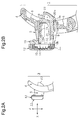
Fig. 1 is a perspective front view showing a cartridge razor according to a first embodiment. -
Fig. 2A is a side view showing a portion of the cartridge razor ofFig. 1 . -
Fig. 2B is a cross-sectional view showing a portion of the cartridge razor ofFig. 1 . -
Fig. 3A is an exploded perspective front view showing the cartridge razor ofFig. 1 in a state in which a blade cartridge is detached from the holder. -
Fig. 3B is an exploded perspective rear view showing the cartridge razor ofFig. 1 in a state in which the blade cartridge is detached from the holder. -
Fig. 4A is an exploded side view showing the cartridge razor ofFig. 3 . -
Fig. 4B is an exploded cross-sectional view showing the cartridge razor ofFig. 3 . -
Fig. 5 is an exploded perspective view showing a blade cartridge of the cartridge razor ofFig. 1 . -
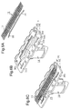
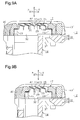
Fig. 6A is a perspective view showing a blade member in which blades are attached to a seat of the blade cartridge ofFig. 5 . -
Fig. 6B is a perspective view showing a blade base member in which a base plate is mounted on a bottom base. -
Fig. 6C is a perspective view showing a state in which the seat of the blade member is mounted on the base plate of the blade base member. -
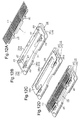
Fig. 7A is a perspective view showing a state in which the blade member is received in the top member of the blade cartridge ofFig. 5 . -
Fig. 7B is a perspective view showing a state in which the blade member and the base plate are received in the top member. -
Figs. 7C and 7D are perspective views each showing the blade cartridge ofFig. 5 as a whole. -
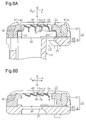
Fig. 8A is an enlarged cross-sectional view taken alongline 8a-8a ofFig. 7D . -
Fig. 8B is an enlarged cross-sectional view taken alongline 8b-8b ofFig. 7D . -
Fig. 9A is an enlarged cross-sectional view corresponding toFig. 8A , showing a blade cartridge of a cartridge razor according to a second embodiment. -
Fig. 9B is an enlarged cross-sectional view corresponding toFig. 8A , showing a blade cartridge of a cartridge razor according to a third embodiment. -
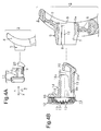
Fig. 10 is an exploded perspective view showing a blade cartridge of a cartridge razor according to a fourth embodiment. -
Figs. 11A, 11 B, 11C, and 11 D are perspective views illustrating a process of manufacturing an auxiliary blade shown inFig. 10 . -
Fig. 12A is a perspective view showing a blade member in which blades are attached to a seat of the blade cartridge ofFig. 10 . -
Fig. 12B is a perspective view showing a bottom base. -
Fig. 12C is a perspective view showing a blade base member in which a base plate is mounted on the bottom base. -
Fig. 12D is a perspective view showing a state in which the seat of the blade member is mounted on the base plate of the blade base member. -
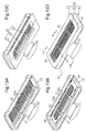
Fig. 13A is a perspective view showing a state in which the blade member is received in the top member of the blade cartridge ofFig. 10 . -
Fig. 13B is a perspective view showing a state in which the blade member and the base plate are received in the top member. -
Figs. 13C and 13D are perspective views each showing the blade cartridge ofFig. 10 as a whole. -
Fig. 14A is an enlarged cross-sectional view taken alongline 14a-14a ofFig. 13D . -
Fig. 14B is an enlarged cross-sectional view taken alongline 14b-14b ofFig. 13D . - A cartridge razor according to a first embodiment will now be described with reference to
Figs. 1 to 8 . - In the cartridge razor, as shown in
Fig. 1 , ablade cartridge 11 is detachably attached to aholder 1. In the respective drawings, regarding the cartridge razor, the direction in which theblade cartridge 11 approaches or separates from the skin when the razor is in use is defined as an x-axis, the direction in which the cutting edge of theblade cartridge 11 extends is defined as a Y-axis, and the direction in which theholder 1 extends is defined as a z-axis. The x-axis, the y-axis, and the z-axis are perpendicular to one another. In the razor, the side close to the user is defined as a front side or a near side and the side separate from the user is defined as a rear side or a back side. - With reference to
Fig. 1 , theholder 1 includes a grip portion 2 gripped by the user and ahead portion 3 arranged at an upper end of the grip portion 2. As shown inFig. 3A , an annular supportingportion 4 is formed in thehead portion 3. Atubular receiving portion 5 is arranged inside the supportingportion 4 through anelastic plate 6. The receivingportion 5 is formed at a core position of the supportingportion 4 to project toward the front side along the x-axis. Referring toFig. 4B , acoupling hole 7, which extends along the x-axis, is formed in the receivingportion 5. Thecoupling hole 7 includes an attachment/detachment port 8, which opens forward, and amanipulation port 9, which opens rearward. As illustrated inFig. 3A , thecoupling hole 7 includes anupper surface 7a and alower surface 7b facing each other along the z-axis and a left surface 7c and aright surface 7d facing each other along the y-axis. Theupper surface 7a and thelower surface 7b are set substantially parallel to each other. The distance between the left surface 7c and theright surface 7d is set to become greater from thelower surface 7b toward theupper surface 7a.Restriction grooves 10, each of which extends along the x-axis, are formed in the left surface 7c and theright surface 7d of thecoupling hole 7. - As shown in
Figs. 4A and 4B , the blade cartridge 11 (the razor head) has ablade assembly 12 and acoupling projection 14. Theblade assembly 12 includes a plurality of (four)blades 13, which are located on the near side of theblade assembly 12 and comes into contact with the skin. Thecoupling projection 14 is coupled to the back side of theblade assembly 12 and extends in a direction separating from theblades 13, or, in other words, rearward. Specifically, referring toFig. 5 , theblade assembly 12 includes ablade member 15, ablade base member 16, and atop member 17. Thecoupling projection 14 is coupled to the rear surface of theblade base member 16. Thetop member 17 is formed in a rectangular frame shape. Theblade member 15 is held between theblade base member 16 and thetop member 17 by being held between theblade base member 16 and thetop member 17. Specific configuration of theblade assembly 12 will be described later. - With reference to
Figs. 3A, 3B ,4A, and 4B , thecoupling projection 14 of theblade cartridge 11 has aguide portion 18, a cantileveredelastic portion 19, and a manipulatingportion 20. Theguide portion 18 is arranged on the back surface of theblade base member 16 of theblade assembly 12 and extends rearward. Theguide portion 18 includes anupper plate portion 18a, aleft plate portion 18c, and aright plate portion 18d. Theupper plate portion 18a extends along the length of theblade assembly 12. Theleft plate portion 18c and theright plate portion 18d are connected to the corresponding opposite ends of theupper plate portion 18a and each extend along the width of theblade assembly 12. In theguide portion 18, the distance between theleft plate portion 18c and theright plate portion 18d is set to become greater toward theupper plate portion 18a. As shown inFig. 3B , restrictingprojections 21, which extend along the x-axis, are formed on the outer surface of theleft plate portion 18c and the outer surface of theright plate portion 18d. Theelastic portion 19 is formed integrally with theguide portion 18 and arranged on the lower side in the space inside theguide portion 18 on the back surface of theblade base member 16 of theblade assembly 12. Theelastic portion 19 is located in an opening of arecess 18b of theguide portion 18. Theelastic portion 19 is flexible along the z-axis. The manipulatingportion 20 is formed integrally with theelastic portion 19 at the distal end of theelastic portion 19. With reference toFig. 4B , the manipulatingportion 20 is formed to extend toward theupper plate portion 18a of theguide portion 18 in a direction perpendicular to the extending direction of theelastic portion 19. Referring toFig. 3B , the manipulatingportion 20 is formed substantially in a trapezoidal columnar shape and has a distal surface inclined with respect to the z-axis. As shown inFig. 4B , a steppedportion 20a is formed between theelastic portion 19 and the manipulatingportion 20. The steppedportion 20a is arranged on the lower side of the boundary portion between theelastic portion 19 and the manipulatingportion 20 and includes the surface of theelastic portion 19 extending along the x-axis and the surface of the manipulatingportion 20 perpendicular to the aforementioned surface of theelastic portion 19. - A method of using the cartridge razor according to the first embodiment will hereafter be described.
- As illustrated in
Figs. 2A ,3A , and4A , thecoupling projection 14 of theblade cartridge 11 is inserted into thecoupling hole 7 of theholder 1 through the attachment/detachment port 8. As theguide portion 18 is inserted into thecoupling hole 7, the outer surface of theupper plate portion 18a, the outer surface of theleft plate portion 18c, and the outer surface of theright plate portion 18d of theguide portion 18 slide on theupper surface 7a, the left surface 7c, and theright surface 7d of thecoupling hole 7, respectively. Meanwhile, the restrictingprojection 21 of theleft plate portion 18c and the restrictingprojection 21 of theright plate portion 18d of theguide portion 18 move in therestriction groove 10 of the left surface 7c and therestriction groove 10 of theright surface 7d of thecoupling hole 7, respectively. When insertion of theblade cartridge 11 into theholder 1 is complete, a holding state in which theblade cartridge 11 is held by theholder 1 is brought about. In the holding state, the steppedportion 20a between theelastic portion 19 and the manipulatingportion 20 is locked to aperipheral portion 9a of themanipulation port 9 and the receivingportion 5 is clamped between theblade base member 16 of theblade assembly 12 and the steppedportion 20a. At this stage, the manipulatingportion 20 projects outward from themanipulation port 9 of thecoupling hole 7 and is thus exposed to the exterior. When theblade cartridge 11 is pressed against the skin surface to be used in the holding state, theelastic plate 6 warps in correspondence with the direction and intensity of the force applied to theblade cartridge 11. This enables theblade cartridge 11 to swing along the three axes. - For example, when the
blade cartridge 11 is arranged in the orientation opposite from the above-described correct orientation of theblade cartridge 11 with respect to theholder 1 and, in this state, is brought close to theholder 1, the outline of theguide portion 18 does not match the shape of thecoupling hole 7 and the positions of the restrictingprojections 21 of theguide portion 18 do not correspond to the positions of therestriction grooves 10 of thecoupling hole 7. This hampers insertion of thecoupling projection 14 of theblade cartridge 11 into thecoupling hole 7 of theholder 1. - To detach the
blade cartridge 11 from theholder 1, the manipulation force is applied to an upper section of the manipulatingportion 20, which is shown inFig. 2 , from the rear side to the front side of theholder 1. This elastically deforms theelastic portion 19 to separate the steppedportion 20a between theelastic portion 19 and the manipulatingportion 20 from theperipheral portion 9a of themanipulation port 9. In this state, theblade cartridge 11 can be spaced from theholder 1 to detach theblade cartridge 11 from theholder 1. - The configuration of the
blade assembly 12 of theblade cartridge 11 will hereafter be described in detail. - As illustrated in
Fig. 5 , theblade member 15 includes aseat 22 in addition to themultiple blades 13. - The
seat 22 is formed by pressing a plate of, for example, austenitic stainless steel. Theseat 22 includes mountingbases 23 and ablade supporting portion 24. The mountingbases 23 include fourleg plates 26, each of which is an example of an elastic leg portion. Eachleg plate 26 extends along the length of theseat 22 to become spaced from the middle of theseat 22. The fourleg plates 26 are arranged in the vicinities of the four corner sections of theseat 22, which has a substantially rectangular shape as viewed along the thickness of theseat 22. Eachleg plate 26 is arranged in an inclined manner to become spaced from theblade supporting portion 24 toward the distal end of theleg plate 26. With reference toFig. 6A , the distal end of eachleg plate 26 has a linear shape along the length of theseat 22. Referring toFig. 6B , the distal end of eachleg plate 26 is held in contact with the upper surface of theblade base member 16. By means of the fourleg plates 26 held in contact with the upper surface of theblade base member 16, theblade supporting portion 24 of theseat 22 is held at a position spaced from the upper surface of theblade base member 16. - As shown in
Figs. 5 ,8A, and 8B , theblade supporting portion 24 includes suspendingarm portions 28 and ablade attachment plate 27. Theblade attachment plate 27 includes a plurality of (four)step plates 29 corresponding to blade mounting portions,reinforcement plate portions 33 corresponding to reinforcement portions, and four bridge portions 30 (coupling portions) that couple the multiple (four)step plates 29 together. Thestep plates 29 are arranged in a stepped manner along the width of theseat 22. As illustrated inFig. 8A , each of thereinforcement plate portions 33 is configured in a bending manner with respect to thecorresponding step plate 29. Eachreinforcement plate portion 33 is bent from the correspondingstep plate 29 toward the inner side of theblade assembly 12. Thestep plates 29, thereinforcement plate portions 33, and thebridge portions 30 are formed integrally with one another. Eachstep plate 29 and eachreinforcement plate portion 33 are formed substantially in an L-shape to define an obtuse angle, which is, for example, approximately 108 degrees, when theblade attachment plate 27 is cut along the width. Thereinforcement plate portions 33 extend along the thickness of theseat 22. Thestep plates 29 are inclined with respect to the width of theseat 22. Specifically, eachstep plate 29 is inclined forward from the basal end of the correspondingreinforcement plate portion 33 to become spaced from theblade base member 16. Thestep plates 29 are located at equal heights along the thickness of theseat 22. With reference toFigs. 5 and8B , the bridge portions 30 (the coupling portions) extend in the arrangement direction of thestep plates 29. The fourbridge portions 30 are spaced apart along the length of eachstep plate 29. The two of the fourbridge portions 30 that are located at the opposite ends of theblade supporting portion 24 correspond to the opposite ends of theseat 22 in the longitudinal direction. A through hole 31 (a shaving scum removal hole) is formed between each adjacent pair of thestep plates 29. The through holes 31 each have an elongated rectangular shape extending along the length of theseat 22 and are arranged along the width of theseat 22. Each of the throughholes 31 is divided by thebridge portions 30 along the length of the throughhole 31. As a result, along the length of theseat 22, three sections of each throughhole 31 are arranged for thecorresponding blade 13. The through holes 31 are formed when thereinforcement plate portions 33 are bent from the plate used to form theseat 22. That is, the area of each throughhole 31 is equal to the area of the correspondingreinforcement plate portion 33. With reference toFig. 8A , a hollow 32 (a shaving scum removal hole), which is arranged in the inner sides of the mountingbases 23, communicates with the exterior through the through holes 31. As shown inFig. 5 , thesuspension arm portions 28 couple theblade attachment plate 27 to the upper and lower mountingbases 23 together. Specifically, two of the foursuspension arm portions 28 are coupled to first ends of the two of thebridge portions 30 located in the middle in the longitudinal direction of theseat 22. The other two of the foursuspension arm portions 28 are coupled to second ends of the aforementioned twobridge portions 30. - With reference to
Figs. 8A and 8B , theblades 13, which are made of metal such as martensitic stainless steel, are arranged on the upper surfaces of thecorresponding step plates 29 of theblade attachment plate 27. Eachblade 13 is fixed to thecorresponding step plate 29 through a plurality of spot welding portions. It is preferable that thereinforcement plate portions 33 be arranged in the blade arrangement direction (along the z-axis) with respect to the spot welding portions. Theblades 13 are arranged on theblade attachment plate 27 in a stepped manner. Each throughhole 31 is located on the inner side of thecutting edge 13a of thecorresponding blade 13. - As illustrated in
Fig. 5 , theblade base member 16 is configured by abottom base 34 made of plastic and abase plate 35 made of aluminum. Theaforementioned coupling projection 14 is coupled to the back surface of thebottom base 34. Thebottom base 34 includes arectangular frame portion 36. Theframe portion 36 includes anupper frame section 36a, alower frame section 36b, aleft frame section 36c, and aright frame section 36d. Theupper frame section 36a and thelower frame section 36b extend along the length of thebottom base 34 and are spaced apart along the width of thebottom base 34. Theleft frame section 36c and theright frame section 36d extend along the width of thebottom base 34 to couple theupper frame section 36a and thelower frame section 36b together at the opposite ends of the upper andlower frame sections upper frame section 36a and thelower frame section 36b are elongated compared to theleft frame section 36c and theright frame section 36d. Theframe portion 36 includes a first inclined frame section that couples a boundary portion between theupper frame section 36a and theright frame section 36d to thecoupling projection 14 and a second inclined frame section that couples the boundary portion between theupper frame section 36a and theleft frame section 36c to thecoupling projection 14. The region surrounded by theframe sections 36a to 36d is divided by the first and second inclined frame sections into three shaving scum removal holes 37. Apositioning hole 44b, which extends through thebottom base 34 along the thickness, is formed in the boundary portion between theupper frame section 36a and theright frame section 36d. Anotherpositioning hole 44b, which extends through thebottom base 34 along the thickness, is formed in the boundary portion between theupper frame section 36a and theleft frame section 36c. Another pair ofpositioning holes 44b, each of which extends through thebottom base 34 along the thickness, is formed in thelower frame section 36b. The twopositioning holes 44b in thelower frame section 36b are located in the vicinity of a middle section of thebottom base 34 compared to the positioning holes 44b in the aforementioned boundary portions. - The
base plate 35 includes anupper frame section 38a extending along the length of thebase plate 35, aleft frame section 38c extending along the width of thebase plate 35 from the left end of theupper frame section 38a, and aright frame section 38d extending along the width of thebase plate 35 from the right end of theupper frame section 38a. That is, thebase plate 35 has a substantially U-shape and forms acutout 39. Referring toFig. 6B , thebase plate 35 is mounted on the upper surface of theupper frame section 36a of thebottom base 34. Thecutout 39 of thebase plate 35 is located over the corresponding shavingscum removal hole 37 between the first and second inclined frame sections in thebottom base 34. This shavingscum removal hole 37 and thecutout 39 communicate with each other. - As illustrated in
Fig. 5 , thetop member 17 is made of plastic and includes arectangular frame portion 41. Theframe portion 41 includes anupper frame section 41 a, alower frame section 41 b, aleft frame section 41 c, and aright frame section 41 d. Theupper frame section 41 a and thelower frame section 41 b extend along the length of thetop member 17 and are spaced apart along the width of thetop member 17. Theleft frame section 41 c and theright frame section 41 d extend along the width of thetop member 17 to connect theupper frame section 41 a and thelower frame section 41 b together at the opposite ends of the upper andlower frame sections upper frame section 41 a and thelower frame section 41 b are elongated compared to theleft frame section 41 c and theright frame section 41 d. Ablade exposing hole 42 is formed in the region surrounded by theframe sections 41 a to 41 d. With reference toFig. 7D , a shavingaid 40, which comes into contact with the skin, is mounted on the upper surface of thelower frame section 41 b of thetop member 17. Referring toFig. 7B , twopositioning shafts 44a, which project toward theblade base member 16, are arranged on an inner surface of theupper frame section 41 a. The twopositioning shafts 44a are located at the opposite ends of theupper frame section 41 a. Similarly, another twopositioning shafts 44a are arranged on an inner surface of thelower frame section 41 b. The twopositioning shafts 44a of theupper frame section 41 a are arranged at positions close to the middle section of thetop member 17 in the longitudinal direction compared to the twopositioning shafts 44a of thelower frame section 41 b. - With reference to
Fig. 5 , with theblade member 15 arranged between theblade base member 16 and thetop member 17, theframe portion 36 of thebottom base 34 and theframe portion 41 of thetop member 17 are placed over each other. At this stage, thepositioning shafts 44a of thetop member 17 are engaged with the corresponding positioning holes 44b of thebottom base 34. Thetop member 17 is thus positioned with respect to thebottom base 34. In this manner, theblade base member 16 and thetop member 17 are joined together. - Referring to
Figs. 6A to 6C , in theblade cartridge 11, two of the fourleg plates 26 of theseat 22 are arranged on the upper surfaces of the corresponding left andright frame sections base plate 35. The other two of the fourleg plates 26 are mounted on the upper surface of thelower frame section 36b. Abuffer member 34a, which is made of metal or plastic, is arranged between the upper surface of thelower frame section 36b and the corresponding twoleg plates 26. - With reference to
Figs. 7C and 7D , the mountingbases 23 of theseat 22 are arranged in the space between the upper andlower frame sections bottom base 34 and the upper andlower frame sections top member 17 to be hidden from the exterior. The opposite ends of eachblade 13, which is supported by theblade supporting portion 24, are located between the left andright frame sections bottom base 34 and the left andright frame sections top member 17. The opposite ends of eachblade 13 are urged toward the inner surfaces of the corresponding left andright frame sections top member 17 by the urging force of theleg plates 26. - As shown in
Fig. 8A , thecutting edge 13a of eachblade 13 is located in the vicinity of a skin contact surface that extends continuously from the front surfaces of the upper andlower frame sections top member 17. Theblades 13 are movable integrally, together with theblade supporting portion 24, in a direction perpendicular to the skin contact surface against elastic force of the mounting bases 23. - With reference to
Fig. 8A , the hollow 32 (which is a shaving scum removal hole), which is located at the inner side of theseat 22, communicates with the exterior from the back surface of theblade assembly 12 through thecutout 39 of thebase plate 35 and the shaving scum removal holes 37 of thebottom base 34 of theblade base member 16. The hollow 32 of theseat 22 communicates with the exterior from the front surface of theblade assembly 12 through the throughholes 31 and theblade exposing hole 42 of thetop member 17. - A method of assembling the
blade cartridge 11 will hereafter be described. - First, as illustrated in
Fig. 7A , theblade member 15 is placed over the inner side of thetop member 17, to which ashaving aid 43 is attached. Then, referring toFig. 7B , thebase plate 35 is placed over theblade member 15. Subsequently, with reference toFig. 7C , thebottom base 34 is placed over thebase plate 35 and thebottom base 34 is coupled to thetop member 17. In this manner, assembly of theblade cartridge 11 is completed. - Operation of the cartridge razor, which is configured as has been described, will now be described.
- When the user uses the razor with the front surface of the
top member 17 and theblades 13 held in contact with the skin surface, the pressing force applied from the skin surface to theblades 13 elastically warps the two mountingbases 23, particularly theleg portions 26, between theblade base member 16 and thetop member 17. This moves theseat 22 integrally with theblades 13 on thestep plates 29. In the first embodiment, by means of thereinforcement plate portions 33, which are formed in theblade attachment plate 27, the rigidity of eachstep plate 29 is set high. The pressing force applied from the skin surface acts on eachreinforcement plate portion 33 in a direction perpendicular to the thickness direction of thereinforcement plate portion 33. This hampers deformation of thereinforcement plate portions 33 caused by the pressing force applied from the skin surface. Thestep plates 29, to which thereinforcement plate portions 33 are coupled, thus resist deformation. In this manner, by improving the rigidity of theblade attachment plate 27, the relative positions of theblades 13 are maintained regardless of the pressing force applied from the skin surface. In contrast, in the conventional configuration in which a blade attachment plate is formed without a reinforcement plate portion, the blade attachment plate is shaped as a flat plate. In this configuration, the pressing force applied from the skin surface acts on the upper surface of the flat plate in a direction perpendicular to the upper surface of the flat plate. The blade attachment plate thus tends to be bent and deformed by the pressing force applied from the skin surface. - In the
blade member 15, shaving scum produced by theblades 13 enters the hollow 32 from theblade exposing hole 42 of thetop member 17 through the throughholes 31 of theblade attachment plate 27. The shaving scum is then discharged to the exterior via the shaving scum removal holes 37 of thebottom base 34. - In a second embodiment, as illustrated in
Fig. 9A , fiveblades 13 are employed. In a third embodiment, as shown inFig. 9B , threeblades 13 are employed. In correspondence with these changes, the shape of theseat 22 is modified, or, in other words, the numbers of thestep plates 29, thereinforcement plate portions 33, and the throughholes 31 of theblade attachment plate 27 are changed. Also, since the size of theseat 22 is changed, the sizes of theblade base member 16 and thetop member 17 are changed correspondingly. The second and third embodiments are configured substantially identical with the first embodiment, except for the aforementioned differences, and have the same advantages as the first embodiment. - A cartridge razor according to a fourth embodiment of the present invention will hereafter be described with reference to
Figs. 10 to 14 .Figs. 10 ,12 ,13 and14 of the fourth embodiment correspond toFig. 5 ,6 ,7 , and8 of the first embodiment, respectively. - As illustrated in
Figs. 13C and 13D , the blade cartridge 11 (the razor head) has theblade assembly 12 and acoupling projection 45. When theblade assembly 12 is in an assembled state, thecoupling projection 45 is arranged between the rear surface of theblade assembly 12 and the side surface of theblade assembly 12 extending along the length. Thecoupling projection 45 extends rearward from theblade assembly 12. With reference toFig. 10 , a plurality of (five)main blades 13 are assembled with theblade assembly 12 at the near side of theblade assembly 12. In the fourth embodiment, the form of thecoupling projection 45 and the form of a holder (not shown) to which thecoupling projection 45 is coupled are different from the forms of the corresponding components of the first embodiment. - The
blade member 15 has a plurality of (five)main blades 13 and oneseat 22. Theblade member 15 is held between theblade base member 16 and thetop member 17. In the fourth embodiment, the forms of theblade member 15, theblade base member 16, and thetop member 17 are also different from the forms of the corresponding components of the first embodiment. - With reference to
Fig. 10 , theseat 22 of theblade member 15 is formed as an integral body by pressing a plate made of metal such as austenitic stainless steel. Theseat 22 is configured by a plurality ofleg portions 46 and theblade supporting portion 24. Theleg portions 46 are arranged on the opposite sides of theblade supporting portion 24 in the width direction and are bent substantially at a right angle toward theblade base member 16 with respect to theblade supporting portion 24. Each three of theleg portions 46 are arranged in the corresponding peripheral portion of theblade supporting portion 24 extending along the length. The middle one of the threeleg portions 46 is elongated compared to the other two of theleg portions 46. Theblade supporting portion 24 is supported by theleg portions 46. Theleg portions 46 are formed integrally with theblade supporting portion 24. In the fourth embodiment, theleg portions 46 of theseat 22 are non-elastic and thus different from the corresponding components of the first embodiment in this regard. - Referring to
Figs. 14A and 14B , a plurality of (five)step plates 29 serving as blade mounting portions, which extend along the length of theseat 22, are formed in theseat 22. Thestep plates 29 are arranged along the width of theseat 22 in a stepped manner. As shown inFig. 10 , four bridge portions 30 (four coupling portions), which each extend in a direction perpendicular to the extending direction of eachstep plate 29, are arranged on theblade attachment plate 27 of theseat 22. The fourbridge portions 30 are spaced apart in the extending direction of eachstep plate 29. The two of the fourbridge portions 30 that are located at the opposite ends correspond to the opposite ends of theseat 22 in the longitudinal direction. Thebridge portions 30 couple thestep plates 29 together. Each through hole 31 (which is a shaving scum removal hole) is formed between the corresponding adjacent pair of thestep plates 29. The through holes 31 each extend along the length of theseat 22. As shown inFig. 10 , the throughholes 31 are arranged on the opposite sides of theseat 22 in the longitudinal direction with respect to thebridge portions 30. Referring toFig. 14A , the hollow 32 (which is a shaving scum removable hole), which is arranged on the inner side of theseat 22, is open to the exterior of thetop member 17 through the through holes 31. - To form each of the through
holes 31, cuts are formed in theblade attachment plate 27 in accordance with the shape of a rectangle defining the outline of the throughhole 31 except for one of the long sides. The cut portions of theblade attachment plate 27 are each bent to define a substantially L-shaped cross section from the correspondingstep plate 29 toward theblade base member 16. In this manner, the reinforcement plate portions 33 (the reinforcement portions) are formed between thecorresponding step plates 29 and theblade base member 16 one by one for each one of the through holes 31. The angle between eachstep plate 29 and the correspondingreinforcement plate portion 33 is, for example, approximately 108 degrees. Thereinforcement plate portions 33 correspond to the throughholes 31 and each extend in the extending direction of thecutting edge 13a of the correspondingmain blade 13. - As shown in
Figs. 14A and 14B , theblades 13, which are identical with those of the first embodiment, are arranged on the upper surfaces of thestep plates 29 of theblade attachment plate 27. Eachblade 13 is fixed to thecorresponding step plate 29 through a plurality of spot welding portions. It is preferable that thereinforcement plate portions 33 be arranged in the blade arrangement direction. Theblades 13 are arranged on theblade attachment plate 27 in a stepped manner. - With reference to
Figs. 12B and 12C , theblade base member 16 is configured by thebottom base 34 made of plastic and thebase plate 35 made of aluminum. Thebottom base 34 includes therectangular frame portion 36. Theframe portion 36 includes theupper frame section 36a, thelower frame section 36b, theleft frame section 36c, and theright frame section 36d. Theupper frame section 36a and thelower frame section 36b each extend along the length of thebottom base 34 and are spaced apart along the width of thebottom base 34. Theleft frame section 36c and theright frame section 36d each extend along the width of thebottom base 34 such that theupper frame section 36a and thelower frame section 36b extend continuous from each other at the opposite ends of the upper andlower frame sections scum removal hole 37 is formed in the region surrounded by theframe sections 36a to 36d. Referring toFig. 12B , four cantilevered bar spring portions 47 (elastic portions) and fourlocking projections 49 are formed on the upper surface of thebottom base 34. Thebar spring portions 47 and the lockingprojections 49 are formed integrally with theframe portion 36. Thebar spring portions 47 are located in correspondence with the four corners of theremoval hole 37 and each extends along the length of thebottom base 34 toward the middle section of thebottom base 34. Each of thebar spring portions 47 is inclined to become spaced from theframe portion 36 from the basal end toward the distal end of thebar spring portion 47. As viewed along the thickness of thebottom base 34, the basal end of eachbar spring portion 47 is placed over an inner peripheral section of theremoval hole 37 and the portion of thebar spring portion 47 extending from the basal end toward the distal end is located over theremoval hole 37. The fourlocking projections 49 are located in correspondence with thebar spring portions 47. In the width direction of thebottom base 34, each two of thebar spring portions 47 are located between the corresponding two of the lockingprojections 49. The distal end of each lockingprojection 49 is bent outward along the width of thebottom base 34. - The
base plate 35 is formed substantially in a C-shape using a flat plate. Specifically, thebase plate 35 includes theupper frame section 38a, theleft frame section 38c, and theright frame section 38d. Theupper frame section 38a extends along the length of thebase plate 35. Theleft frame section 38c extends along the width of thebase plate 35 from the left end of theupper frame section 38a. The distal end of theleft frame section 38c is bent inward substantially at a right angle. Theright frame section 38d extends along the width of thebase plate 35 from the right end of theupper frame section 38a. The distal end of theright frame section 38d is bent inward substantially at a right angle. Theright frame section 38d and theleft frame section 38c are each formed substantially in an L-shape. Thecutout 39 is formed in thebase plate 35. Thebase plate 35 is mounted on the upper surface of theupper frame section 36a of thebottom base 34. Thecutout 39 of thebase plate 35 is located over theremoval hole 37 of thebottom base 34. Thecutout 39 and theremoval hole 37 thus communicate with each other. - As illustrated in
Fig. 10 , thetop member 17 is made of plastic and includes therectangular frame portion 41. Theframe portion 41 includes theupper frame section 41 a, thelower frame section 41 b, theleft frame section 41 c, and theright frame section 41 d. Theupper frame section 41 a and thelower frame section 41 b each extend along the length of thetop member 17 and are spaced apart along the width of thetop member 17. Theleft frame section 41 c and theright frame section 41 d each extend along the width of thetop member 17 to couple theupper frame section 41 a and thelower frame section 41 b together at the opposite ends of the upper andlower frame sections blade exposing hole 42 is formed in the region surrounded by theframe sections 41 a to 41 d. Four locking recesses 50, with which the distal ends of the lockingprojections 49 of thebottom base 34 are engageable, are formed in theframe portion 41. Two of the locking recesses 50 are formed in the inner surfaces of theupper frame section 41 a at the opposite ends in the longitudinal direction. The other two of the locking recesses 50 are formed in the inner surfaces of thelower frame section 41 b at the opposite ends in the longitudinal direction. A pair ofpositioning projections 52b, which is spaced apart along the length of theupper frame section 41 a, is formed on the bottom surface of theupper frame section 41 a. Theaforementioned coupling projection 45 is attached to the lower end of thelower frame section 41 b. - With reference to
Figs. 13A to 13D , an annularsmoother functioning portion 48 is arranged on the skin contact surface of thetop member 17. Surface modification treatment is performed on the plastic that constitutes thesmoother functioning portion 48 to provide a hydrophilic property to thesmoother functioning portion 48. The surface of thesmoother functioning portion 48 thus holds water to generate a thin water film on the skin contact surface of theblade cartridge 11. This facilitates slide of theblade cartridge 11 when the razor is used, thus improving shaving comfort. After the use of the razor, the surface of thesmoother functioning portion 48 dries to remove the water that has been held by the surface. The state before the use, in which the surface of thesmoother functioning portion 48 does not hold the water, is thus restored. This restrains melting of thesmoother functioning portion 48 when the razor is in use, thus ensuring the function of thesmoother functioning portion 48 even after repeated use of the razor. - As illustrated in
Figs. 10 and14A , anauxiliary blade 51 is arranged between theblade base member 16 and thetop member 17. Theauxiliary blade 51 is an independent component of theblade assembly 12. With reference toFig. 11 D , theauxiliary blade 51 is formed using a metal plate to define a substantially L-shaped cross section and is configured by asupport plate portion 52 and ablade plate portion 53. Referring toFig. 11 D , thesupport plate portion 52 and theblade plate portion 53 are bent substantially at a right angle through abent portion 55. Theblade plate portion 53 includes acutting edge 53a, which is formed in the peripheral portion of theauxiliary blade 51 extending along the length. As shown inFig. 14A , thesupport plate portion 52 is clamped between theblade base member 16 and thetop member 17. Thecutting edge 53a of theblade plate portion 53 is exposed to the exterior of theblade assembly 12. Thecutting edge 53a of theblade plate portion 53, which is an auxiliary cutting edge, faces substantially in the opposite direction to the facing direction of thecutting edge 13a of eachmain blade 13. Thecutting edge 53a of theblade plate portion 53, which is the auxiliary cutting edge, is arranged on a side surface of theblade assembly 12. The cutting edges 13a of themain blades 13 are arranged on the upper surface of theblade assembly 12. With reference toFig. 11 D , a pair ofpositioning holes 52a, which extends through thesupport plate portion 52 along the thickness, is formed in thesupport plate portion 52. The twopositioning holes 52a are spaced apart along the length of theauxiliary blade 51. - A method of assembling the
blade cartridge 11 according to the fourth embodiment will hereafter be described. - As shown in
Figs. 12C and 12D , thebase plate 35 is mounted on the distal ends of thebar spring portions 47 of thebottom base 34. Theblade member 15 is then arranged in an upper section of thebottom base 34. Referring toFig. 14A , thebase plate 35 supports a portion of theblade member 15 so that thebase plate 35 is mounted between the pairs of theleg portions 46 facing in the width direction of theseat 22. When thebar spring portions 47 are not in elastic deformation, theleg portions 46 of theseat 22 of theblade member 15 are spaced from thebottom base 34. Subsequently, as illustrated inFig. 10 , theframe portion 36 of thebottom base 34 and theframe portion 41 of thetop member 17 are placed over each other with theauxiliary blade 51 clamped between theframe portions projections 49 of thebottom base 34 are engaged with the corresponding locking recesses 50 of thetop member 17 and thepositioning projections 52b of thetop member 17 are engaged with thecorresponding positioning holes 52a of theauxiliary blade 51. Theauxiliary blade 51 is thus fixed between thebottom base 34 and thetop member 17. In this manner, theblade base member 16 and thetop member 17 are joined to each other. The lockingprojections 49 and the locking recesses 50 each correspond to a positioning portion. Assembly of theblade cartridge 11 is thus completed in the above-described manner. - In the assembled
blade cartridge 11, theleg portions 46 of theseat 22 are inserted into the gaps between the upper andlower frame sections bottom base 34 and the corresponding upper andlower frame sections top member 17 and thus become hidden from the exterior. The opposite ends of eachblade 13 in the longitudinal direction of theblade member 15 are inserted between the left andright frame sections bottom base 34 of theblade base member 16 and the corresponding left andright frame sections top member 17. Theseat 22 is urged toward the inner surfaces of the left andright frame sections top member 17 by the elastic force of thebar spring portions 47 and is pushed down. The cutting edges 13a of theblades 13 are located in the vicinity of the skin contact surface extending continuously from the front surfaces of the upper andlower frame sections top member 17. Theblades 13 are movable, together with theblade supporting portion 24, each in an inward direction perpendicular to the skin contact surface against the elastic force of thebar spring portions 47. When theblades 13 are moved together with theblade supporting portion 24 by a predetermined amount, theleg portions 46 of theseat 22 come into contact with thebottom base 34. This restricts movement of theblades 13 beyond the predetermined amount. - Also in the fourth embodiment, by means of the
reinforcement plate portions 33, which are formed in theblade attachment plate 27, the rigidity of thestep plates 29 is set high. This maintains the relative positions of theblades 13. Shaving scum generated by theblades 13 enters the hollow 32 through theblade exposing hole 42 of thetop member 17 and the throughholes 31 of theblade attachment plate 27. The shaving scum is then discharged to the exterior through theremoval hole 37 of thebottom base 34. Also, the razor of the fourth embodiment is enabled to shave by causing thebottom base 34 of theblade base member 16 to contact the skin surface together with theauxiliary blade 51. - Referring to
Fig. 14A , the hollow 32 (which is a shaving scum removal hole) on the inner side of theseat 22 in theblade member 15 communicates with the exterior from the back surface of theblade assembly 12 through thecutout 39 of thebase plate 35 and the shavingscum removal hole 37 of thebottom base 34. Also, the hollow 32 in theseat 22 communicates with the exterior from the front surface of theblade assembly 12 through the throughholes 31 of theseat 22 and theblade exposing hole 42 of thetop member 17. - A method of forming the
auxiliary blade 51 will hereafter be described. - As illustrated in
Fig. 11A , a substantiallyrectangular plate 54, which is, for example, an SUS420J2 material of stainless steel, is prepared. A plurality of holes is formed by pressing the material. With reference toFig. 11 B , thecutting edge 53a is formed on a first edge of the two edges of theplate 54 extending along the length. Subsequently, referring toFig. 11C , theplate 54 is bent along a bending line extending along the length of theplate 54, which is set between a second side edge of the aforementioned two side edges, and thecutting edge 53a. Next, acutting line 56a extending along the length of theplate 54 is set between the second side edge of theplate 54 and thebent portion 55. Theplate 54 is then cut along thecutting line 56a. Acut plate section 56 is thus separated from theplate 54 and, as a result, theauxiliary blade 51 is completed. Bending illustrated inFig. 11C or cutting illustrated inFig. 11 D may be carried out by a razor head assembling machine, for example, when theblade member 15 is arranged between thetop member 17 and theblade base member 16. - The present embodiment has the following advantages.
- (1) In the
blade cartridge 11, thereinforcement plate portions 33 are arranged on thestep plates 29. This maintains a high rigidity in thestep plates 29 even when, for example, the thickness of theblade supporting portion 24 is set small to such an extent that bending of theblade supporting portion 24 or welding of theblades 13 to thestep plates 29 are facilitated. As a result, even with the through holes 31 (which are shaving scum removal holes) formed in theblade supporting portion 24, deformation of theblade supporting portion 24 is restrained and shaving comfort of the razor is maintained.
Theblades 13 are attached to thestep plates 29 through spot welding or the like. Thereinforcement plate portions 33 restrain promotion of deformation of theblade supporting portion 24 by the heat generated when theblades 13 are attached to thestep plates 29. - (2) In the
blade supporting portion 24 of theblade cartridge 11, thereinforcement plate portions 33 are bent from theblade supporting portion 24 toward theblade base member 16. Thereinforcement plate portions 33 are thus formed in the hollow 32 of theseat 22. In this manner, thereinforcement plate portions 33 are easily formed simply by bending theblade supporting portion 24. Also, thereinforcement plate portions 33 are arranged without interfering with the use of the razor. - (3) Each
reinforcement plate portion 33 is bent from the correspondingstep plate 29 toward theblade base member 16 at the boundary between thereinforcement plate portion 33 and thestep plate 29 and along the length of theblade supporting portion 24. In this manner, thereinforcement plate portions 33 are easily formed when the shaving scum removal holes 31 are formed. Thereinforcement plate portions 33 and the shaving scum removal holes 31 are both arranged one by one for each of thestep plates 29. This improves rigidity of theblade supporting portion 24 as a whole and facilitates removal of shaving scum to the exterior. - (4) The
razor head 11 having theblade 51 includes theblade member 15 in which themain blades 13 are arranged, theblade base member 16 located on the back side of therazor head 11, and thetop member 17 located on the near side of therazor head 11. Theblade member 15 is arranged between theblade base member 16 and thetop member 17. The cutting edges 13a of themain blades 13 of theblade member 15 are exposed to the exterior through thetop member 17. Theauxiliary blade 51 is arranged between theblade base member 16 and thetop member 17. Thecutting edge 53a of theauxiliary blade 51 is exposed to the side opposite from the side that thecutting edges 13a of themain blades 13 face. Thesupport plate portion 52, which is clamped between theblade base member 16 and thetop member 17, and theblade plate portion 53 having thecutting edge 53a are arranged in theauxiliary blade 51. Theblade plate portion 53 is bent from thesupport plate portion 52 toward the side corresponding to theblade base member 16.
A razor head of a razor disclosed in Japanese National Phase Laid-Open Patent Publication No.2007-528268
In the configuration of the fourth embodiment, theauxiliary blade 51 is arranged at the side opposite from the side that thecutting edges 13a of themain blades 13 face. Theauxiliary blade 51 is bent such that thecutting edge 53a faces the side corresponding to theblade base member 16. Theauxiliary blade 51 is thus attachable to therazor head 11 with thesupport plate portion 52 or thebent portion 55, which is between thesupport plate portion 52 and theblade plate portion 53, maintained in a supported state. This ensures a simple blade attachment structure with a smaller number of components. - (5) The method of forming the
auxiliary blade 51 for the razor having theblade plate portion 53 having thecutting edge 53a and thesupport plate portion 52 includes a step of forming thecutting edge 53a in the first side edge portion of the two side edges on the opposing sides of a plate, a step of bending the plate between the second side edge portion of the two sides on the opposing sides of the plate, and a step of cutting the cutstep plate portion 56 away from the plate along thecutting line 56a, which is located between thebent portion 55 formed in the previous step and the second side edge portion of the plate and extends along the length of the plate. The method facilitates the forming of theauxiliary blade 51 using the plate. - Other than the illustrated embodiments, the configurations described below, for example, may be employed.
- A plurality of
separate blade members 15 may be prepared and arranged along the width of eachblade member 15 between theblade base member 16 and thetop member 17. In this case, the total number of theblades 13 of the razor corresponds to the number determined by multiplying the number of theblades 13 of eachblade member 15 by the number of theblade members 15. For example, in a case of afirst blade member 15 having threeblades 13 combined with asecond blade member 15 having threeblades 13, ablade cartridge 11 having sixblades 13 is configured. Alternatively, in a case of afirst blade member 15 having threeblades 13 combined with asecond blade member 15 having twoblades 13, ablade cartridge 11 having fiveblades 13 is configured. Also, in a case of afirst blade member 15 having twoblades 13 combined with asecond blade member 15 having twoblades 13, ablade cartridge 11 having fourblades 13 is configured. - The direction in which the
reinforcement plate portions 33 are bent is not restricted to the direction of the illustrated embodiments. Specifically, in each of the illustrated embodiments, eachreinforcement plate portion 33 is bent along the bending line that is located at the boundary portion between thereinforcement plate portion 33 and thecorresponding step plate 29 and extends along the length of theblade supporting portion 24, or in direction perpendicular to the elevation ofFig. 8A . The direction of the bending line may be changed. For example, eachreinforcement plate portion 33 may be bent from the correspondingstep plate 29 or the correspondingbridge portion 30 along a bending line that extends along the width of theblade supporting portion 24. - Each
reinforcement plate portion 33 may be discontinuous in the extending direction of thereinforcement plate portion 33 and thus be divided into multiple sections. In this case, the extending length of eachreinforcement plate portion 33 is set preferably to 50% or greater and, more preferably, to 75% or greater, with respect to the extending length of eachstep plate 29. - As long as the rigidity of each
step plate 29 is improved, the form of each of thereinforcement plate portions 33, which are arranged on thestep plates 29, may be modified. For example, a plurality of reinforcement plate portions may be placed over the back side of eachstep plate 29. - The
reinforcement plate portions 33 may be configured separately from theseat 22. In this case, thereinforcement plate portions 33 are coupled to theseat 22 using coupling means such as welding, adhesive, or bolts and nuts. - The
seat 22 may be formed by a method other than pressing, which is, for example, injection molding. - Each
reinforcement plate portion 33 may be bent from theblade supporting portion 24 toward theblade base member 16 substantially by 180 degrees and placed over theblade supporting portion 24. - The
bridge portions 30 may be configured separately from theblade supporting portion 24. In this configuration, thebridge portions 30 are coupled to theblade supporting portion 24 using the aforementioned coupling means. - 11...Blade Cartridge (Razor Head), 13...Blade, 13a...Cutting Edge, 15...Blade Member, 16...Blade Base Member, 17...Top Member, 24...Blade Supporting Portion, 29...Step Plate (Blade Mounting Portion), 30...Bridge Portion (Coupling Portion), 31...Through Hole (Shaving Scum Removal Hole), 33...Reinforcement Plate Portion (Reinforcement Portion).
Claims (16)
- A razor comprising:a blade member including blades and a blade supporting portion;a blade base member arranged on a back side of the blade member; anda top member arranged on a near side of the blade member to hold the blade member between the top member and the blade base member with the blades of the blade member exposed to the exterior, the razor being characterized in that the blade supporting portion includes:a plurality of blade mounting portions arranged in a direction in which the blades are arranged;a reinforcement portion that improves rigidity of the blade mounting portions; anda coupling portion that couples the blade mounting portions together.
- The razor according to claim 1, characterized in that the reinforcement portion is formed by being bent from the blade mounting portions.
- The razor according to claim 1, characterized in that the reinforcement portion is arranged between the blade mounting portions and the blade base member by being bent from the blade mounting portions toward the blade base member.
- The razor according to claim 1, characterized in that the reinforcement portion is arranged between the blade mounting portions and the blade base member.
- The razor according to any one of claims 1 to 4, characterized in that the blade mounting portions extend in an extending direction of the blades.
- The razor according to any one of claims 1 to 5, characterized in that the reinforcement portion is one of a plurality of reinforcement portions that is arranged one by one for each of the blade mounting portions.
- The razor according to any one of claims 1 to 6, characterized in that the blade mounting portions and the reinforcement portion are formed integrally with one another.
- The razor according to any one of claims 1 to 6, characterized in that the blade mounting portions, the reinforcement portion, and the coupling portion are formed integrally with one another.
- The razor according to any one of claims 1 to 8, characterized in that the coupling portion extends in an arrangement direction of the blades to couple the blade mounting portions together.
- The razor according to claim 9, characterized in that
the blade supporting portion has shaving scum removal holes, which are located on both sides of the coupling portion and arranged in the extending direction of the blade supporting portion, and
the removal holes extend in an extending direction of cutting edges of the blades in correspondence with the cutting edges of the blades. - The razor according to claim 10, characterized in that each of the reinforcement portions is bent toward the blade base member from one of two sides of the corresponding blade mounting portion in a blade arrangement direction, the one side being opposite from the cutting edge of the associated blade.
- The razor according to claim 10 or 11, characterized in that the reinforcement portions extend in the extending direction of the cutting edge of each blade in correspondence with the shaving scum removal holes.
- The razor according to any one of claims 1 to 12, characterized in that a seat arranged in the blade member has a mounting base that is formed integrally with the seat and supported by the blade base member.
- The razor according to claim 13, characterized in that an elastic portion is arranged between the mounting base of the seat and the blade base member to allow the blade member to move integrally in correspondence with pressing force applied to the blades of the blade member when the blades contact a skin surface.
- The razor according to claim 14, characterized in that the mounting base of the seat has an elastic leg portion that is supported by the blade base member to allow the blade member to move integrally in correspondence with pressing force applied to the blades of the blade member when the blades contact a skin surface.
- The razor according to claim 14, characterized in that the blade base member has an elastic portion that supports the blade member to allow the blade member to move integrally in correspondence with pressing force applied to the blades of the blade member when the blades contact a skin surface.
Applications Claiming Priority (2)
| Application Number | Priority Date | Filing Date | Title |
|---|---|---|---|
| JP2013245130A JP6293464B2 (en) | 2013-11-27 | 2013-11-27 | razor |
| PCT/JP2014/081149 WO2015080113A1 (en) | 2013-11-27 | 2014-11-26 | Razor |
Publications (3)
| Publication Number | Publication Date |
|---|---|
| EP3075498A1 true EP3075498A1 (en) | 2016-10-05 |
| EP3075498A4 EP3075498A4 (en) | 2017-10-11 |
| EP3075498B1 EP3075498B1 (en) | 2020-09-02 |
Family
ID=53199053
Family Applications (1)
| Application Number | Title | Priority Date | Filing Date |
|---|---|---|---|
| EP14865095.5A Active EP3075498B1 (en) | 2013-11-27 | 2014-11-26 | Razor |
Country Status (4)
| Country | Link |
|---|---|
| US (1) | US10183408B2 (en) |
| EP (1) | EP3075498B1 (en) |
| JP (1) | JP6293464B2 (en) |
| WO (1) | WO2015080113A1 (en) |
Cited By (8)
| Publication number | Priority date | Publication date | Assignee | Title |
|---|---|---|---|---|
| US9993931B1 (en) | 2016-11-23 | 2018-06-12 | Personal Care Marketing And Research, Inc. | Razor docking and pivot |
| DE102018105821A1 (en) * | 2018-03-13 | 2019-09-19 | Beiersdorf Aktiengesellschaft | WET SHAVER-shaving |
| USD884970S1 (en) | 2019-02-27 | 2020-05-19 | PCMR International Ltd. | Razor cartridge guard |
| USD884969S1 (en) | 2019-02-27 | 2020-05-19 | Pcmr International Ltd | Combined razor cartridge guard and docking |
| USD884971S1 (en) | 2019-02-27 | 2020-05-19 | Pcmr International Ltd | Razor cartridge |
| US11000960B1 (en) | 2020-11-16 | 2021-05-11 | Personal Care Marketing And Research, Inc. | Razor exposure |
| US11117280B2 (en) | 2016-03-18 | 2021-09-14 | Personal Care Marketing & Research, Inc. | Razor cartridge |
| DE102020130698A1 (en) | 2020-11-20 | 2022-05-25 | LORD International Co. | Blade unit for a wet razor |
Families Citing this family (18)
| Publication number | Priority date | Publication date | Assignee | Title |
|---|---|---|---|---|
| JP6293464B2 (en) * | 2013-11-27 | 2018-03-14 | 株式会社貝印刃物開発センター | razor |
| US10870212B2 (en) * | 2015-09-09 | 2020-12-22 | Beiersdorf Ag | Safety razor and blade unit for safety razor |
| DE102016101672A1 (en) * | 2016-01-29 | 2017-08-03 | Beiersdorf Aktiengesellschaft | Nassrasiergriff |
| GB2551199B (en) * | 2016-06-10 | 2019-12-18 | Advanced Risc Mach Ltd | Video data processing system |
| KR101730415B1 (en) * | 2016-06-24 | 2017-04-26 | 주식회사 도루코 | Razor with perforated handle |
| DE102018105823A1 (en) * | 2018-03-13 | 2019-09-19 | Beiersdorf Aktiengesellschaft | WET SHAVER-shaving |
| EP3774230A1 (en) | 2018-03-30 | 2021-02-17 | The Gillette Company LLC | Razor handle with a pivoting portion |
| EP3546156B1 (en) | 2018-03-30 | 2021-03-10 | The Gillette Company LLC | Razor handle with a pivoting portion |
| BR112020020132A2 (en) | 2018-03-30 | 2021-01-05 | The Gillette Company Llc | HANDLE OF SHAVING OR DEVILING APPLIANCE WITH MOBILE LIMBS |
| WO2019191345A1 (en) | 2018-03-30 | 2019-10-03 | The Gillette Company Llc | Razor handle with a pivoting portion |
| CN111886115B (en) | 2018-03-30 | 2022-04-19 | 吉列有限责任公司 | Razor cartridge |
| USD874061S1 (en) | 2018-03-30 | 2020-01-28 | The Gillette Company Llc | Shaving razor cartridge |
| CN111867795B (en) | 2018-03-30 | 2022-03-18 | 吉列有限责任公司 | Razor handle |
| US11691307B2 (en) | 2018-03-30 | 2023-07-04 | The Gillette Company Llc | Razor handle with a pivoting portion |
| WO2019191178A1 (en) | 2018-03-30 | 2019-10-03 | The Gillette Company Llc | Razor handle with movable members |
| US11607820B2 (en) | 2018-03-30 | 2023-03-21 | The Gillette Company Llc | Razor handle with movable members |
| EP3771530A1 (en) * | 2019-07-31 | 2021-02-03 | Bic Violex S.A. | Mechanical assembly of a skin care device, skin care device and process for manufacturing thereof |
| MX2022005479A (en) * | 2020-10-30 | 2022-06-02 | Kai R&D Center Co Ltd | Razor. |
Family Cites Families (16)
| Publication number | Priority date | Publication date | Assignee | Title |
|---|---|---|---|---|
| GB1591095A (en) | 1976-11-16 | 1981-06-17 | Wilkinson Sword Ltd | Shaving units |
| DE3167072D1 (en) * | 1980-08-07 | 1984-12-13 | Gillette Co | Razor blade assembly |
| DE9108213U1 (en) | 1991-07-03 | 1992-10-29 | Wilkinson Sword Gmbh, 5650 Solingen, De | |
| ES2192546T3 (en) | 1999-11-29 | 2003-10-16 | Koninkl Philips Electronics Nv | SHAVING MACHINER GIVEN WITH A RASURATING HEAD THAT HAS A SECONDARY FRAME AND A MAIN FRAME. |
| US7617607B2 (en) | 2003-07-21 | 2009-11-17 | The Gillette Company | Shaving razors and other hair cutting assemblies |
| US7272991B2 (en) * | 2004-02-09 | 2007-09-25 | The Gillette Company | Shaving razors, and blade subassemblies therefor and methods of manufacture |
| US7621203B2 (en) * | 2004-02-09 | 2009-11-24 | The Gillette Company | Shaving razors, and blade subassemblies therefor and methods of manufacture |
| JP4950507B2 (en) * | 2006-02-14 | 2012-06-13 | 株式会社貝印刃物開発センター | razor |
| JP4977374B2 (en) * | 2006-02-14 | 2012-07-18 | 株式会社貝印刃物開発センター | razor |
| JP4950506B2 (en) | 2006-02-14 | 2012-06-13 | 株式会社貝印刃物開発センター | razor |
| MX2008016496A (en) * | 2006-06-20 | 2009-03-02 | Bic Violex Sa | Razor blade unit head and safety razor including such a blade unit. |
| ES2383167T3 (en) * | 2008-05-22 | 2012-06-18 | Feintechnik Gmbh Eisfeld | Razor blade unit with cutting edge housing |
| JP5465869B2 (en) * | 2008-12-05 | 2014-04-09 | 株式会社貝印刃物開発センター | Replaceable blade razor |
| JP6250357B2 (en) | 2013-10-15 | 2017-12-20 | 株式会社貝印刃物開発センター | Replacement blade removable razor |
| JP6293464B2 (en) * | 2013-11-27 | 2018-03-14 | 株式会社貝印刃物開発センター | razor |
| GB2531491A (en) * | 2014-01-16 | 2016-04-27 | The King Of Shaves Company Ltd | Razor Blade Cartridges |
-
2013
- 2013-11-27 JP JP2013245130A patent/JP6293464B2/en active Active
-
2014
- 2014-11-26 US US15/038,928 patent/US10183408B2/en active Active
- 2014-11-26 EP EP14865095.5A patent/EP3075498B1/en active Active
- 2014-11-26 WO PCT/JP2014/081149 patent/WO2015080113A1/en active Application Filing
Cited By (16)
| Publication number | Priority date | Publication date | Assignee | Title |
|---|---|---|---|---|
| US11117280B2 (en) | 2016-03-18 | 2021-09-14 | Personal Care Marketing & Research, Inc. | Razor cartridge |
| US11712814B2 (en) | 2016-03-18 | 2023-08-01 | Dollar Shave Club, Inc. | Razor cartridge |
| US10538007B2 (en) | 2016-11-23 | 2020-01-21 | Personal Care Marketing And Research, Inc. | Razor docking |
| US10569435B2 (en) | 2016-11-23 | 2020-02-25 | Personal Care Marketing And Research, Inc. | Razor docking |
| US9993931B1 (en) | 2016-11-23 | 2018-06-12 | Personal Care Marketing And Research, Inc. | Razor docking and pivot |
| US11745371B2 (en) | 2016-11-23 | 2023-09-05 | Dollar Shave Club, Inc. | Razor cartridge |
| US11298845B2 (en) | 2016-11-23 | 2022-04-12 | Dollar Shave Club, Inc. | Razor docking |
| DE102018105821A1 (en) * | 2018-03-13 | 2019-09-19 | Beiersdorf Aktiengesellschaft | WET SHAVER-shaving |
| USD884970S1 (en) | 2019-02-27 | 2020-05-19 | PCMR International Ltd. | Razor cartridge guard |
| USD884971S1 (en) | 2019-02-27 | 2020-05-19 | Pcmr International Ltd | Razor cartridge |
| USD884969S1 (en) | 2019-02-27 | 2020-05-19 | Pcmr International Ltd | Combined razor cartridge guard and docking |
| US11254022B1 (en) | 2020-11-16 | 2022-02-22 | Personal Care Marketing And Research, Inc. | Razor exposure |
| US11000960B1 (en) | 2020-11-16 | 2021-05-11 | Personal Care Marketing And Research, Inc. | Razor exposure |
| US11752649B2 (en) | 2020-11-16 | 2023-09-12 | Dollar Shave Club, Inc. | Razor exposure |
| DE102020130698A1 (en) | 2020-11-20 | 2022-05-25 | LORD International Co. | Blade unit for a wet razor |
| WO2022106518A1 (en) | 2020-11-20 | 2022-05-27 | LORD International Co. | Blade unit for a wet razor |
Also Published As
| Publication number | Publication date |
|---|---|
| EP3075498A4 (en) | 2017-10-11 |
| US10183408B2 (en) | 2019-01-22 |
| JP6293464B2 (en) | 2018-03-14 |
| US20170001323A1 (en) | 2017-01-05 |
| WO2015080113A1 (en) | 2015-06-04 |
| EP3075498B1 (en) | 2020-09-02 |
| JP2015100621A (en) | 2015-06-04 |
Similar Documents
| Publication | Publication Date | Title |
|---|---|---|
| EP3075498B1 (en) | Razor | |
| US10751894B2 (en) | Shaving blade cartridge | |
| CN111902249B (en) | Trimming blade and body hair cutting device | |
| JP6792059B2 (en) | Razor cartridge for shaving and how to assemble it | |
| US8465232B2 (en) | Cutting tool having a retractable nozzle | |
| EP3492227B1 (en) | Razor cartridge | |
| EP3659732A1 (en) | Holder for cutting tool | |
| KR20180094848A (en) | Shaving head | |
| KR102449754B1 (en) | razor system | |
| EP2752275B1 (en) | Cutting instrument | |
| KR101729807B1 (en) | Detachable insert type cutting tool | |
| JP2017221234A (en) | cutter knife | |
| JP4037439B2 (en) | Electric razor | |
| JP2017148918A (en) | Insert clamp mechanism of blade edge replaceable grooving tool and clamp working tool | |
| CN117295575A (en) | Cutting insert and cutting tool assembly including the same | |
| JPH0722212Y2 (en) | Support structure of blade in razor | |
| JP4766547B2 (en) | Clippers | |
| EP4212269A1 (en) | Tool head in head replaceable cutting tool | |
| JP5415213B2 (en) | Knife | |
| JP2005185580A (en) | Hair cutter | |
| JP4388825B2 (en) | Long handle razor | |
| KR100870098B1 (en) | Cover holder's combination structure and combination materials of small-size electrical component | |
| JP3825306B2 (en) | Throw-away tool for grooving | |
| JP4832127B2 (en) | plane | |
| JP2009298056A (en) | Indexing apparatus |
Legal Events
| Date | Code | Title | Description |
|---|---|---|---|
| PUAI | Public reference made under article 153(3) epc to a published international application that has entered the european phase |
Free format text: ORIGINAL CODE: 0009012 |
|
| 17P | Request for examination filed |
Effective date: 20160524 |
|
| AK | Designated contracting states |
Kind code of ref document: A1 Designated state(s): AL AT BE BG CH CY CZ DE DK EE ES FI FR GB GR HR HU IE IS IT LI LT LU LV MC MK MT NL NO PL PT RO RS SE SI SK SM TR |
|
| AX | Request for extension of the european patent |
Extension state: BA ME |
|
| DAX | Request for extension of the european patent (deleted) | ||
| A4 | Supplementary search report drawn up and despatched |
Effective date: 20170911 |
|
| RIC1 | Information provided on ipc code assigned before grant |
Ipc: B26B 21/52 20060101ALI20170905BHEP Ipc: B26B 21/40 20060101ALI20170905BHEP Ipc: B26B 21/22 20060101AFI20170905BHEP |
|
| STAA | Information on the status of an ep patent application or granted ep patent |
Free format text: STATUS: EXAMINATION IS IN PROGRESS |
|
| 17Q | First examination report despatched |
Effective date: 20190314 |
|
| GRAP | Despatch of communication of intention to grant a patent |
Free format text: ORIGINAL CODE: EPIDOSNIGR1 |
|
| STAA | Information on the status of an ep patent application or granted ep patent |
Free format text: STATUS: GRANT OF PATENT IS INTENDED |
|
| INTG | Intention to grant announced |
Effective date: 20200527 |
|
| GRAS | Grant fee paid |
Free format text: ORIGINAL CODE: EPIDOSNIGR3 |
|
| GRAA | (expected) grant |
Free format text: ORIGINAL CODE: 0009210 |
|
| STAA | Information on the status of an ep patent application or granted ep patent |
Free format text: STATUS: THE PATENT HAS BEEN GRANTED |
|
| AK | Designated contracting states |
Kind code of ref document: B1 Designated state(s): AL AT BE BG CH CY CZ DE DK EE ES FI FR GB GR HR HU IE IS IT LI LT LU LV MC MK MT NL NO PL PT RO RS SE SI SK SM TR |
|
| REG | Reference to a national code |
Ref country code: GB Ref legal event code: FG4D |
|
| REG | Reference to a national code |
Ref country code: AT Ref legal event code: REF Ref document number: 1308302 Country of ref document: AT Kind code of ref document: T Effective date: 20200915 Ref country code: CH Ref legal event code: EP |
|
| REG | Reference to a national code |
Ref country code: DE Ref legal event code: R096 Ref document number: 602014069841 Country of ref document: DE |
|
| REG | Reference to a national code |
Ref country code: IE Ref legal event code: FG4D |
|
| REG | Reference to a national code |
Ref country code: LT Ref legal event code: MG4D |
|
| PG25 | Lapsed in a contracting state [announced via postgrant information from national office to epo] |
Ref country code: BG Free format text: LAPSE BECAUSE OF FAILURE TO SUBMIT A TRANSLATION OF THE DESCRIPTION OR TO PAY THE FEE WITHIN THE PRESCRIBED TIME-LIMIT Effective date: 20201202 Ref country code: HR Free format text: LAPSE BECAUSE OF FAILURE TO SUBMIT A TRANSLATION OF THE DESCRIPTION OR TO PAY THE FEE WITHIN THE PRESCRIBED TIME-LIMIT Effective date: 20200902 Ref country code: LT Free format text: LAPSE BECAUSE OF FAILURE TO SUBMIT A TRANSLATION OF THE DESCRIPTION OR TO PAY THE FEE WITHIN THE PRESCRIBED TIME-LIMIT Effective date: 20200902 Ref country code: NO Free format text: LAPSE BECAUSE OF FAILURE TO SUBMIT A TRANSLATION OF THE DESCRIPTION OR TO PAY THE FEE WITHIN THE PRESCRIBED TIME-LIMIT Effective date: 20201202 Ref country code: FI Free format text: LAPSE BECAUSE OF FAILURE TO SUBMIT A TRANSLATION OF THE DESCRIPTION OR TO PAY THE FEE WITHIN THE PRESCRIBED TIME-LIMIT Effective date: 20200902 Ref country code: GR Free format text: LAPSE BECAUSE OF FAILURE TO SUBMIT A TRANSLATION OF THE DESCRIPTION OR TO PAY THE FEE WITHIN THE PRESCRIBED TIME-LIMIT Effective date: 20201203 Ref country code: SE Free format text: LAPSE BECAUSE OF FAILURE TO SUBMIT A TRANSLATION OF THE DESCRIPTION OR TO PAY THE FEE WITHIN THE PRESCRIBED TIME-LIMIT Effective date: 20200902 |
|
| REG | Reference to a national code |
Ref country code: NL Ref legal event code: MP Effective date: 20200902 |
|
| REG | Reference to a national code |
Ref country code: AT Ref legal event code: MK05 Ref document number: 1308302 Country of ref document: AT Kind code of ref document: T Effective date: 20200902 |
|
| PG25 | Lapsed in a contracting state [announced via postgrant information from national office to epo] |
Ref country code: RS Free format text: LAPSE BECAUSE OF FAILURE TO SUBMIT A TRANSLATION OF THE DESCRIPTION OR TO PAY THE FEE WITHIN THE PRESCRIBED TIME-LIMIT Effective date: 20200902 Ref country code: LV Free format text: LAPSE BECAUSE OF FAILURE TO SUBMIT A TRANSLATION OF THE DESCRIPTION OR TO PAY THE FEE WITHIN THE PRESCRIBED TIME-LIMIT Effective date: 20200902 Ref country code: PL Free format text: LAPSE BECAUSE OF FAILURE TO SUBMIT A TRANSLATION OF THE DESCRIPTION OR TO PAY THE FEE WITHIN THE PRESCRIBED TIME-LIMIT Effective date: 20200902 |
|
| PG25 | Lapsed in a contracting state [announced via postgrant information from national office to epo] |
Ref country code: SM Free format text: LAPSE BECAUSE OF FAILURE TO SUBMIT A TRANSLATION OF THE DESCRIPTION OR TO PAY THE FEE WITHIN THE PRESCRIBED TIME-LIMIT Effective date: 20200902 Ref country code: RO Free format text: LAPSE BECAUSE OF FAILURE TO SUBMIT A TRANSLATION OF THE DESCRIPTION OR TO PAY THE FEE WITHIN THE PRESCRIBED TIME-LIMIT Effective date: 20200902 Ref country code: EE Free format text: LAPSE BECAUSE OF FAILURE TO SUBMIT A TRANSLATION OF THE DESCRIPTION OR TO PAY THE FEE WITHIN THE PRESCRIBED TIME-LIMIT Effective date: 20200902 Ref country code: PT Free format text: LAPSE BECAUSE OF FAILURE TO SUBMIT A TRANSLATION OF THE DESCRIPTION OR TO PAY THE FEE WITHIN THE PRESCRIBED TIME-LIMIT Effective date: 20210104 Ref country code: NL Free format text: LAPSE BECAUSE OF FAILURE TO SUBMIT A TRANSLATION OF THE DESCRIPTION OR TO PAY THE FEE WITHIN THE PRESCRIBED TIME-LIMIT Effective date: 20200902 Ref country code: CZ Free format text: LAPSE BECAUSE OF FAILURE TO SUBMIT A TRANSLATION OF THE DESCRIPTION OR TO PAY THE FEE WITHIN THE PRESCRIBED TIME-LIMIT Effective date: 20200902 |
|
| PG25 | Lapsed in a contracting state [announced via postgrant information from national office to epo] |
Ref country code: ES Free format text: LAPSE BECAUSE OF FAILURE TO SUBMIT A TRANSLATION OF THE DESCRIPTION OR TO PAY THE FEE WITHIN THE PRESCRIBED TIME-LIMIT Effective date: 20200902 Ref country code: AT Free format text: LAPSE BECAUSE OF FAILURE TO SUBMIT A TRANSLATION OF THE DESCRIPTION OR TO PAY THE FEE WITHIN THE PRESCRIBED TIME-LIMIT Effective date: 20200902 Ref country code: AL Free format text: LAPSE BECAUSE OF FAILURE TO SUBMIT A TRANSLATION OF THE DESCRIPTION OR TO PAY THE FEE WITHIN THE PRESCRIBED TIME-LIMIT Effective date: 20200902 Ref country code: IS Free format text: LAPSE BECAUSE OF FAILURE TO SUBMIT A TRANSLATION OF THE DESCRIPTION OR TO PAY THE FEE WITHIN THE PRESCRIBED TIME-LIMIT Effective date: 20210102 |
|
| REG | Reference to a national code |
Ref country code: DE Ref legal event code: R097 Ref document number: 602014069841 Country of ref document: DE |
|
| PG25 | Lapsed in a contracting state [announced via postgrant information from national office to epo] |
Ref country code: MC Free format text: LAPSE BECAUSE OF FAILURE TO SUBMIT A TRANSLATION OF THE DESCRIPTION OR TO PAY THE FEE WITHIN THE PRESCRIBED TIME-LIMIT Effective date: 20200902 Ref country code: SK Free format text: LAPSE BECAUSE OF FAILURE TO SUBMIT A TRANSLATION OF THE DESCRIPTION OR TO PAY THE FEE WITHIN THE PRESCRIBED TIME-LIMIT Effective date: 20200902 |
|
| REG | Reference to a national code |
Ref country code: CH Ref legal event code: PL |
|
| PLBE | No opposition filed within time limit |
Free format text: ORIGINAL CODE: 0009261 |
|
| STAA | Information on the status of an ep patent application or granted ep patent |
Free format text: STATUS: NO OPPOSITION FILED WITHIN TIME LIMIT |
|
| PG25 | Lapsed in a contracting state [announced via postgrant information from national office to epo] |
Ref country code: LU Free format text: LAPSE BECAUSE OF NON-PAYMENT OF DUE FEES Effective date: 20201126 |
|
| 26N | No opposition filed |
Effective date: 20210603 |
|
| REG | Reference to a national code |
Ref country code: BE Ref legal event code: MM Effective date: 20201130 |
|
| PG25 | Lapsed in a contracting state [announced via postgrant information from national office to epo] |
Ref country code: DK Free format text: LAPSE BECAUSE OF FAILURE TO SUBMIT A TRANSLATION OF THE DESCRIPTION OR TO PAY THE FEE WITHIN THE PRESCRIBED TIME-LIMIT Effective date: 20200902 Ref country code: CH Free format text: LAPSE BECAUSE OF NON-PAYMENT OF DUE FEES Effective date: 20201130 Ref country code: SI Free format text: LAPSE BECAUSE OF FAILURE TO SUBMIT A TRANSLATION OF THE DESCRIPTION OR TO PAY THE FEE WITHIN THE PRESCRIBED TIME-LIMIT Effective date: 20200902 Ref country code: LI Free format text: LAPSE BECAUSE OF NON-PAYMENT OF DUE FEES Effective date: 20201130 |
|
| PG25 | Lapsed in a contracting state [announced via postgrant information from national office to epo] |
Ref country code: IT Free format text: LAPSE BECAUSE OF FAILURE TO SUBMIT A TRANSLATION OF THE DESCRIPTION OR TO PAY THE FEE WITHIN THE PRESCRIBED TIME-LIMIT Effective date: 20200902 Ref country code: IE Free format text: LAPSE BECAUSE OF NON-PAYMENT OF DUE FEES Effective date: 20201126 |
|
| PG25 | Lapsed in a contracting state [announced via postgrant information from national office to epo] |
Ref country code: TR Free format text: LAPSE BECAUSE OF FAILURE TO SUBMIT A TRANSLATION OF THE DESCRIPTION OR TO PAY THE FEE WITHIN THE PRESCRIBED TIME-LIMIT Effective date: 20200902 Ref country code: MT Free format text: LAPSE BECAUSE OF FAILURE TO SUBMIT A TRANSLATION OF THE DESCRIPTION OR TO PAY THE FEE WITHIN THE PRESCRIBED TIME-LIMIT Effective date: 20200902 Ref country code: CY Free format text: LAPSE BECAUSE OF FAILURE TO SUBMIT A TRANSLATION OF THE DESCRIPTION OR TO PAY THE FEE WITHIN THE PRESCRIBED TIME-LIMIT Effective date: 20200902 |
|
| PG25 | Lapsed in a contracting state [announced via postgrant information from national office to epo] |
Ref country code: MK Free format text: LAPSE BECAUSE OF FAILURE TO SUBMIT A TRANSLATION OF THE DESCRIPTION OR TO PAY THE FEE WITHIN THE PRESCRIBED TIME-LIMIT Effective date: 20200902 |
|
| PG25 | Lapsed in a contracting state [announced via postgrant information from national office to epo] |
Ref country code: BE Free format text: LAPSE BECAUSE OF NON-PAYMENT OF DUE FEES Effective date: 20201130 |
|
| PGFP | Annual fee paid to national office [announced via postgrant information from national office to epo] |
Ref country code: GB Payment date: 20231026 Year of fee payment: 10 |
|
| PGFP | Annual fee paid to national office [announced via postgrant information from national office to epo] |
Ref country code: FR Payment date: 20231120 Year of fee payment: 10 Ref country code: DE Payment date: 20231121 Year of fee payment: 10 |