EP3074587B1 - Continuous vacuum transport system and method - Google Patents
Continuous vacuum transport system and method Download PDFInfo
- Publication number
- EP3074587B1 EP3074587B1 EP14866176.2A EP14866176A EP3074587B1 EP 3074587 B1 EP3074587 B1 EP 3074587B1 EP 14866176 A EP14866176 A EP 14866176A EP 3074587 B1 EP3074587 B1 EP 3074587B1
- Authority
- EP
- European Patent Office
- Prior art keywords
- vacuum
- holding tank
- conduit
- valve
- cuttings
- Prior art date
- Legal status (The legal status is an assumption and is not a legal conclusion. Google has not performed a legal analysis and makes no representation as to the accuracy of the status listed.)
- Active
Links
Images


Classifications
-
- E—FIXED CONSTRUCTIONS
- E21—EARTH OR ROCK DRILLING; MINING
- E21B—EARTH OR ROCK DRILLING; OBTAINING OIL, GAS, WATER, SOLUBLE OR MELTABLE MATERIALS OR A SLURRY OF MINERALS FROM WELLS
- E21B21/00—Methods or apparatus for flushing boreholes, e.g. by use of exhaust air from motor
- E21B21/06—Arrangements for treating drilling fluids outside the borehole
- E21B21/063—Arrangements for treating drilling fluids outside the borehole by separating components
- E21B21/065—Separating solids from drilling fluids
-
- B—PERFORMING OPERATIONS; TRANSPORTING
- B65—CONVEYING; PACKING; STORING; HANDLING THIN OR FILAMENTARY MATERIAL
- B65G—TRANSPORT OR STORAGE DEVICES, e.g. CONVEYORS FOR LOADING OR TIPPING, SHOP CONVEYOR SYSTEMS OR PNEUMATIC TUBE CONVEYORS
- B65G53/00—Conveying materials in bulk through troughs, pipes or tubes by floating the materials or by flow of gas, liquid or foam
- B65G53/04—Conveying materials in bulk pneumatically through pipes or tubes; Air slides
- B65G53/24—Gas suction systems
-
- E—FIXED CONSTRUCTIONS
- E21—EARTH OR ROCK DRILLING; MINING
- E21B—EARTH OR ROCK DRILLING; OBTAINING OIL, GAS, WATER, SOLUBLE OR MELTABLE MATERIALS OR A SLURRY OF MINERALS FROM WELLS
- E21B21/00—Methods or apparatus for flushing boreholes, e.g. by use of exhaust air from motor
- E21B21/06—Arrangements for treating drilling fluids outside the borehole
-
- E—FIXED CONSTRUCTIONS
- E21—EARTH OR ROCK DRILLING; MINING
- E21B—EARTH OR ROCK DRILLING; OBTAINING OIL, GAS, WATER, SOLUBLE OR MELTABLE MATERIALS OR A SLURRY OF MINERALS FROM WELLS
- E21B43/00—Methods or apparatus for obtaining oil, gas, water, soluble or meltable materials or a slurry of minerals from wells
- E21B43/25—Methods for stimulating production
- E21B43/26—Methods for stimulating production by forming crevices or fractures
- E21B43/2607—Surface equipment specially adapted for fracturing operations
Definitions
- Industrial processes produce mixtures of particles and/or fluids that are separated and/or filtered by filtration systems. To reduce waste and cost, one part of the mixture is recaptured and/or recycled. Due to space limitations, other parts of the mixture are stored and/or treated off-site. In one example, a gyratory sifter separates particles above a certain size from the mixture.
- a vibratory shaker separates drill cuttings and drill fluid from a slurry.
- the drill fluid is recaptured while the drill cuttings are collected.
- space limitations do not allow storage of drill cuttings on-site for extended periods of time. Additionally, cuttings are often contaminated by the drilling fluid. To conform to environmental standards, cuttings are treated before disposal. However, cuttings are treated off site due to the space limitations of the drilling rig.
- the drill cuttings are temporarily stored and then removed for processing at a separate treatment facility and/or disposal facility. The drill cuttings are loaded into containers for transport by trucks or ships.
- the output of the filtration system may be a distance from the location of the cuttings storage area and/or transportation area. Accordingly, the cuttings are moved from the filtration system to the transportation location using, for example front end loaders. However, in some locales, such as a deep sea rig, front loaders are impractical and/or dangerous.
- One or more augers are also used to transport the cuttings to the storage system and/or transportation system.
- operating and/or maintaining the augers is hazardous.
- the augers have a rotating helical screw blade, known as the flight, that acts as a screw conveyor to move the cuttings through a trough from the filtration system to the storage system and/or transport system.
- the trough and flight are either covered or protected by fencing and/or railing. In locations with space limitations, the precautions required to safely operate the augers make their use impractical.
- Exemplary embodiments disclosed herein relate to transporting cuttings discharged from a filtration system to a storage area. More specifically, the exemplary embodiments disclosed herein relate to a system and a method of transporting cuttings from an industrial filtration system to a storage area using continuous vacuum and/or continuous pressure. Cuttings, as used herein, refer to the residual portion of a mixture that does not pass through the filter media of a filtration system.
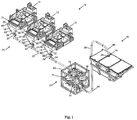
- Fig. 1 generally illustrates an embodiment of a solids control system 10.
- the solids control system 10 may be part of a larger system, such as a drilling system for on-shore oil drilling and/or off-shore oil drilling.
- a drilling system for on-shore oil drilling and/or off-shore oil drilling such as a drilling system for on-shore oil drilling and/or off-shore oil drilling.
- the disclosed embodiments are not limited to on-shore oil drilling and/or off-shore oil drilling.
- the disclosed embodiment may be used in conjunction with any system requiring cuttings to be transported.
- the solids control system 10 may have a filtration system 12, a continuous vacuum transport system 14 and/or a discharge collection system 15.
- the filtration system 12 may receive a mixture and may separate the mixture into a cuttings portion and a filtrate portion.
- the filtration system 12 may direct the filtrate portion into a filtrate storage container (17 in Fig. 2 ), such as a sump, a pan and/or a reservoir. Further, the filtration system 12 may direct the cuttings portion to an outlet 13 of the filtrate system 13.
- the filtration system 12 may be a shale shaker. In that embodiment, the filtration system 12 may separate a slurry of drill cuttings and drilling fluid and may output the drill cuttings as the cuttings portion at the outlet 13.
- the filtration system 12 may be a gyratory sifter. In that embodiment, the filtration system 12 may separate a mixture of different sized particles. The filtration system 12 may output particles that do not pass through a mesh screen as the cuttings portion.
- cuttings portion will refer to any particulate matter that does not pass through a filtering element, e.g., screen. In other words the “cuttings portion” will refer to a portion that is not a filtrate portion.
- the continuous vacuum transport system 14 may have a discharge manifold 18, a vacuum conduit 20, a vacuum hub 22, a control system (24 in Fig. 2 ), a transport conduit 26 and/or a discharge outlet 28.
- the discharge manifold 18 is in particulate communication with the outlet 13 of the filtrate system 12. In other words, the discharge manifold 18 may receive the cuttings portion from the filtration system 12.
- the term "in particulate communication with” is used to describe two components such that the cuttings portion is moved from the first component to the second component.
- the discharge manifold 18 connects the vacuum conduit 20 to the filtrate system 12.
- a partial vacuum may be applied to the vacuum conduit 20 so that the cuttings portion is drawn from the discharge manifold 18 though the vacuum conduit 20 into the vacuum hub 22.
- the cuttings portion may travel through the vacuum hub 22 into the transport conduit 26.
- Pressure may be applied to the transport conduit 26 and may push the cuttings portion from the vacuum hub 22 through the transport conduit 26 to the discharge outlet 28.
- the discharge outlet 28 may feed into the discharge collection system 15.
- the discharge collection system 15 may include a container 16. In other embodiments, the collection system 15 may include a pit, a ship, a cuttings blower, or other collection means known in the art.
- the discharge manifold 18 includes a manifold body 30, a manifold valve 32 and a manifold conduit 34.
- the manifold body 30 may have an opening 36 and an exit 38. Further, the manifold body 30 may have a top 40 and a bottom 42. The opening 36 may be wider than the exit 38 of the manifold body 30.
- the manifold body 30 may taper from the opening 36 at the top 40 to the exit 38 at the bottom 42.
- the cuttings portion from the filtration system 12 may be deposited into the opening 36 of the manifold body 30. In an embodiment, the cuttings portion from more than one filtration system 12 may be deposited into the opening 36 of the manifold body 30. The taper of the manifold body 30 may cause the cuttings portion to funnel to the exit 38 of the manifold body 30.
- the manifold valve 32 may be connected to the exit 38 of the manifold body 30.
- the manifold valve 32 may also be connected to the manifold conduit 34.
- the manifold conduit 34 may connect the manifold valve 32 to the vacuum conduit 20.
- a vacuum in the vacuum conduit 20 may cause a pressure differential to form at the opening 36 of the manifold body 30.
- the pressure differential may cause the cuttings portion to pass through the manifold valve 32 and the manifold conduit 34 and may cause the cuttings portion to enter the vacuum conduit 20.
- the manifold valve 32 may be shut by the control system 24 ( Fig. 2 ) to regulate the movement of the cuttings portion into the vacuum conduit 20.
- the vacuum transport system 14 includes a vacuum conduit 20 having a first end 44 and a second end 46.
- the first end 44 of the vacuum conduit 20 may be connected to the manifold conduit 34 of the discharge manifold 18.
- the continuous vacuum transport system 14 may have a plurality of discharge manifolds 18.
- a plurality of the filtration systems 12 may be connected to the plurality of the discharge manifolds 18.
- the plurality of the discharge manifolds 18 may be connected to the first end 44 of the vacuum conduit 20 through the manifold conduit 34 of the discharge manifolds 18.
- the second end 46 of the vacuum conduit 20 may be connected to the vacuum hub 22.
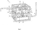
- Fig. 4 shows a detail view of vacuum hub 22.
- the vacuum hub 22 may have an inlet 48, an outlet 50, a plurality of holding tanks 52 and a vacuum pump 54.
- the inlet 48 of the vacuum hub 22 may be connected to the second end 46 of the vacuum conduit 20.
- the inlet 48 may also be connected to holding tanks 52 such that the vacuum conduit 20 is in particulate communication with the holding tanks 52 via the inlet 48.
- the plurality of holding tanks 52 may be connected to the inlet 48 of the vacuum hub 22 and the outlet 50 of the vacuum hub 22.
- the vacuum hub 22 may have a frame 58 that defines an interior portion 60 of the vacuum hub 22.
- the holding tanks 52 may be located within the interior portion 60 of the frame 58.
- the frame 58 may be configured to accommodate the holding tanks 52 in different positions.
- the holding tanks 52 may be positioned next to each other on a vertical plane.
- one or more of the holding tanks 52 may be elevated in the frame 58 relative to the rest of the holding tanks 52. Accordingly, the configuration of the holding tanks 52 within the frame is not intended to limit the scope of the present disclosure.
- each of the plurality of holding tanks 52 may have a pressure vessel 62, an inlet valve 64, an outlet valve 66 and a level sensor 68.
- the pressure vessel 62 may have a top 70 and a bottom 72.
- the inlet valve 64 may be connected to the top 70 of the pressure vessel 62.
- the inlet valve 64 may be connected to the inlet 48 of the vacuum hub 22.
- the cuttings portion may travel from the vacuum conduit 20, through the inlet 48 of the vacuum hub 22, through the inlet valve 64 and into the pressure vessel 62 of one of the holding tanks 52.
- the control system 24 may open and/or shut the inlet valves 64 of one or more of the holding tanks 52 to direct the flow of the cuttings portion.
- the outlet valve 66 may be connected to the bottom 72 of the pressure vessel 62.
- the outlet valve 66 may be connected to the outlet 50 of the vacuum hub 22.
- the control system 24 may open and/or shut the outlet valves 66 of one or more of the holding tanks 52 to direct the flow of the cuttings portion.
- the level sensor 68 may detect the level of the cuttings portion in the pressure vessel 62. In an embodiment, the level sensors 68 may communicate to the control system 24 whether the pressure vessels 62 are each empty or full. In another embodiment, the level sensors 68 may communicate a value representing an amount of the cuttings portion in each of the pressure vessels 62.
- each of the pressure vessels 62 may have a cylindrical portion 76 and a conical portion 78.
- the cylindrical portion 76 may be located at the top 70 of the pressure vessel 62, and the conical portion 78 may be located at the bottom 72 of the pressure vessel 62.
- the cylindrical portion 76 and the conical portion 78 may be joined at a junction point 80.
- the conical portion 78 may taper until connecting to the outlet valve 66.
- the pressure vessel 62 may have a plurality of tabs 82 to connect the pressure vessel 62 to the frame 58 of the vacuum hub 22.
- the plurality of tabs 82 may be spaced substantially equally around the junction point 80 of the pressure vessel 62.
- the pressure vessel 62 may be connected to the vacuum pump 54 of each of the holding tanks 52.
- the vacuum pump 54 may supply a vacuum to the holding tanks 52 when the inlet valve 64 of the holding tank 52 is open and the outlet valve 66 of the holding tank 52 is closed.
- the vacuum supplied to the holding tank 52 by the vacuum pump 54 creates a pressure differential between the first end 44 of the vacuum conduit 20 and the pressure vessel 62 of the holding tank 52.
- the cuttings portion may flow into the holding tank 52.
- the vacuum pump 54 may supply pressure to the top 70 of the pressure vessel 62 when the outlet valve 66 of the holding tank 52 is open and the inlet valve 64 of the holding tank 52 is closed. The pressure may cause the cuttings portion to flow from the holding tank 52 though the outlet valve 66.
- the vacuum hub 22 may have a first vacuum pump 54a and a second vacuum pump 54b to cause the cuttings portion to flow in and out of the pressure vessel 62.
- the first vacuum pump 54a may supply a vacuum to the pressure vessels 62 when the pressure vessels 62 are filling.
- the second vacuum pump 54b may supply a pressure to the holding tanks 52 when the pressure vessels 62 are emptying.
- the vacuum hub 22 may have a pressure tank 56.
- the pressure tank 56 may be connected to the top 70 of the pressure vessels 62 of each of the holding tanks 52.
- a plurality of pressure assist conduits 74 may connect the pressure tank 56 to the top 70 of the pressure vessels 62.
- the pressure tank 56 may supply pressure to the holding tank 52 to empty the cuttings portion from the holding tank 52. Additionally, as illustrated in Fig. 4 , the pressure tank 56 may be located within the interior portion 60 of the frame 58.
- the transport conduit 26 may have a first end 84 and a second end 86.
- the first end 84 of the transport conduit 26 may be connected to the outlet 50 of the vacuum hub 22.
- the second end 86 of the transport conduit 26 may be connected to the discharge outlet 28, which is connected to the collection system 15.
- the vacuum pump 54 through the outlet valve 66 of one of the holding tanks 52, may supply pressure to the first end 84 of the transport conduit 26 to push the cuttings portion from the first end 84 of the transport conduit 26 to the second end 86 of the transport conduit 26.
- the control system 24 may be connected to the manifold valve 32 of the discharge manifold 18.
- the control system 24 may open and/or close the manifold valve 32 to control the flow of the cuttings portion into the vacuum conduit 20. Additionally, the control system 24 may open and/or may close the manifold valve 32 to control the amount of vacuum pressure that may be used by the continuous vacuum transport system 14 from the vacuum pump 54.
- the control system 24 may close the manifold valve 32 of the discharge manifold 18 when the filtration system 12 that may be feeding the discharge manifold 18 is offline.
- the control system 24 may also be connected to the inlet valve 64, the outlet valve 66 and the level sensor 68 of each of the holding tanks 52 of the vacuum hub 22.
- the control system 24 may open the inlet valve 64 and may close the outlet valve 66 of the holding tank 52. Additionally, to empty one of the holding tanks 52, the control system 24 may close the inlet valve 64 and may open the outlet valve 66 of the holding tank 52. When one of the holding tanks 52 is not being emptied or filled, the control system 24 may close the inlet valve 64 and the outlet valve 66 of the holding tank 52. The control system 24 may determine whether one or more of the holding tanks 52 are full or empty by communicating with the level sensors 68 of the holding tanks 52.
- the control system 24 may be a computer system and/or discrete electronic hardware. Additionally, the control system 24 may be autonomous and/or may accept input by a user. In an embodiment, the control system 24 may be located at the vacuum hub 22. In another embodiment, the control system 24 may be located at a central control center. In an embodiment, the control system 24 may be part of a larger system to control the operation of an industrial process, such as a fluids control system in on-shore oil drilling and/or off-shore oil drilling.
- the vacuum hub 22 may have two holding tanks 52.
- the control system 24 may cause one of the holding tanks 52 to fill while causing the other holding tank 52 to empty.
- the pressure in the transport conduit 26 and/or vacuum in the vacuum conduit 20 that may be supplied by the vacuum pump 54 may be configured so that the time required to empty one of the holding tanks 52 is less than or equal to the time required to fill the other holding tank 52.
- the vacuum hub 22 may have three or more holding tanks 52.
- the control system 24 may fill one of the holding tanks 52 and may empty one of the holding tanks 52. Additionally, the control system 24 may hold one or more of the holding tanks 52 so that the holding tanks 52 are neither filling nor emptying. In this embodiment, the control system 24 may rotate (or change) transportation of the cuttings portion between the holding tanks 52.
- the discharge manifold 18 may receive the cuttings portion from the filtration system 12.
- the vacuum pump 54 may cause a pressure differential between the first end 44 of the vacuum conduit 20 and the second end 46 of the vacuum conduit 20.
- the cuttings portion may move from the discharge manifold 18 to the second end of the vacuum conduit 20.
- the cuttings portion may move from each of the discharge manifolds 18 to the second end 46 of the vacuum conduit 20.
- the cuttings portion may travel from the second end 46 of the vacuum conduit 20 into the inlet 48 of the vacuum hub 22.
- the control system 24 may control the inlet valves 64 of the holding tanks 52 to direct the cuttings portion into at least one of the holding tanks 52.
- the control system 24 may control the holding tanks 52a, 52b, 52c, and 52d so that the cuttings portion is filling at least one of the holding tanks 52a, 52b, 52c, and 52d and the cuttings portion is emptied from at least one of the holding tanks 52a, 52b, 52c, and 52d.
- the control system 24 may assign one of a plurality of states 88a, 88b, 88c and 88d to each of the holding tanks 52a, 52b, 52c, and 52d.
- the plurality of states may be defined as a filling state 88a, an emptying state 88b, a full state 88c and an empty state 88d.
- the control system 24 may manipulate the inlet valve 64 and/or outlet valve 66 of each of the holding tanks 52a, 52b, 52c, and 52d to create the plurality of states 88a, 88b, 88c and 88d.
- the inlet valve 64 of the holding tank 52 may be open, and the outlet valve 66 of the holding tank 52 may be closed.
- the emptying state 88b the inlet valve 64 of the holding tank 52 may be closed, and the outlet valve 66 of the holding tank 52 may be open.
- the full state 88c and the empty state 88d the inlet valve 64 of the holding tank 52 may be closed, and the outlet valve 66 of the holding tank 52 may be closed.
- the control system 24 may use the level sensors 68 of the holding tanks 52 to determine when the holding tanks 52 in the filling state 88a is full and may then put the holding tank 52 in the full state 88c. When the holding tank 52 transitions from the filling state 88a to the full state 88c, the control system 24 may select one of the holding tanks 52 to transition from the empty state 88d to the filling state 88a.
- control system 24 may use the level sensors 68 of the holding tanks 52 to determine when one of the holding tanks 52 in the emptying state 88b is empty and may transition the holding tank 52 into the empty state 88d. When the holding tank 52 transitions to the empty state 88d from the emptying state 88c, the control system 24 may select one of the holding tanks 52 in the full state 88c to transition to the emptying state 88b.
- the vacuum hub 22 may have two holding tanks 52.
- the holding tanks 52 may transition between the filling state 88a and the emptying state 88b.
- the vacuum hub 22 may have more than two of the holding tanks 52.
- the control system 24 may rotate which of the holding tanks 52 is placed in the filling state 88a and which of the holding tanks 52 is placed in the emptying state 88b.
- the holding tanks 52 may transition into the empty state 88d between the emptying state 88b and the filling state 88a.
- a flow diagram illustrates an embodiment of the solids control system incorporating a continuous vacuum transport system.
- Fig. 6 illustrates flows and connectivity between the holding tanks 52a, 52b, 52c, and 52d of the vacuum hub 22.
- a cuttings portion flow 90 is shown with directional arrows to indicate direction of travel of the cuttings portion.
- a pressure flow 91 is shown with directional arrows to indicate the application of pressure to the holding tanks 52.
- a vacuum flow 92 is shown with directional arrows to indicate the application of vacuum to the holding tanks 52.
- the pressure flow 91 may be controlled and/or directed by valves 94.
- the valves 94 may be connected in the pressure flow 91 to the holding tanks 52a, 52b, 52c, and 52d.
- the valves 94 may be controlled by the control system 24.
- the vacuum flow 92 may be controlled and/or directed by valves 93.
- the valves 93 may be connected in the vacuum flow 92 to the holding tanks 52a, 52b, 52c, and 52d.
- the valves 93 may be controlled by the control system 24.
- the cuttings portion flow 90 may supply the cuttings portion to the holding tanks 52 of the vacuum hub 22.
- the valves 64 may be connected in the supply of the cuttings portion flow 90 to the holding tanks 52a, 52b, 52c, and 52d.
- the valves 64 may be controlled by the control system 24.
- the valves 66 may be connected at the bottom 72 of the holding tanks 52a, 52b, 52c, and 52d.
- the valves 66 may be connected in the discharge of the cuttings portion flow 90 from the holding tanks 52a, 52b, 52c, and 52d to the outlet 50 of the vacuum hub 22.
- the directional arrows of the cuttings portion flow 90 indicate travel of the supply of the cuttings portion from right to left.
- the directional arrows of the cuttings portion flow 90 indicate travel of the discharge of the cuttings portion from left to right.
- the cuttings portion may be drawn from the discharge manifold 18 though the vacuum conduit 20 into the vacuum hub 22.
- the cuttings portion may enter through the inlet 48 of the vacuum hub 22 as shown in Fig. 4 .
- the cuttings portion may travel into one of the holding tanks 52a, 52b, 52c, and 52d of the vacuum hub 22.
- Fig. 6 also illustrates air bypass lines 95.
- the air bypass lines 95 may connect each holding tank 52 to another holding tank 52.
- the air bypass lines 95 may connect each holding tank 52 to an adjacent holding tank 52.
- the air bypass lines 95 may have valves 96.
- the valves 96 may be controlled by the control system 24.
- air bypass line 95a may be connected at the top 70 of holding tank 52a and at the top 70 of holding tank 52b to allow air flow between holding tank 52a and holding tank 52b.
- air bypass line 95b may be connected at the top 70 of holding tank 52b and at the top 70 of holding tank 52c to allow airflow between holding tank 52b and holding tank 52c.
- air bypass line 95c may be connected at the top 70 of holding tank 52c to the top 70 of holding tank 52d to allow airflow between holding tank 52c and holding tank 52d.
- air bypass line 95d may be connected at the top 70 of holding tank 52d to the top 70 of holding tank 52a to allow air flow between holding tank 52d and holding tank 52a.
- the air bypass lines 95a, 95b, 95c and 95d may have corresponding valves 96a, 96b, 96c and 96d.
- the valves 96 may be controlled by the control system 24.
- the cuttings portion of the cuttings portion flow 90 may begin flowing into holding tank 52a.
- the supply of the cuttings portion may enter the holding tank 52a when the valve 64a is open and the valve 66a at the bottom 72 of the holding tank 52a is closed.
- the cuttings portion may accumulate in the holding tank 52a and may fill the holding tank 52a.
- a vacuum may be applied to the holding tank 52a.
- the vacuum may be provided by the vacuum flow 92 when the valve 93b and valve 96a in the air bypass line 95a is also open. The vacuum may create suction within the holding tank 52a to draw the cuttings portion into the holding tank 52a as shown.
- the holding tank 52d may discharge the cuttings portion through the valve 66d into the discharge of the cuttings portion flow 90.
- a pressure may be applied to the holding tank 52d.
- the pressure may be provided by the pressure flow 91 when the valve 94d is open. The pressure may force the cuttings portion out of the holding tank 52d and into the discharge of the cuttings portion flow 90 as shown.
- the cuttings portion may move from the holding tank 52d, through the valve 66d to the outlet 50 of the vacuum hub 22.
- the control system 24 may control the holding tanks 52a, 52b, 52c, and 52d so that the cuttings portion is filling one of the holding tanks 52a, 52b, 52c, and 52d and the cuttings portion is emptied from one of the holding tanks 52a, 52b, 52c, and 52d.
- the control system 24 may rotate which of the holding tanks 52 is placed in the filling state and which of the holding tanks 52 is placed in the emptying state.
- Fig. 6 illustrates a particular state of the holding tanks 52.
- the holding tank 52a may be described as the suction tank.
- the cuttings portion flow 90 may be entering the holding tank 52a placing the holding tank 52a in the filling state.
- the holding tank 52b may be described as the ready tank to become the next in succession to be placed in the filling state.
- the holding tank 52c may be in an empty state.
- the holding tank 52d may be described as the discharge tank.
- the cuttings portion flow 90 may be discharging from the holding tank 52d placing the holding tank 52d in the emptying state.
- the vacuum flow 92 may pull air from the holding tank 52b with the valve 96a of the air bypass line 95a open. As a result, the vacuum in the holding tank 52a may be transferred to the holding tank 52b and the cuttings portion may enter the holding tank 52b. This operation may prevent the cutting portion from entering in the vacuum flow 92 which may cause vacuum pump damage.
- the process shifts, so that: 1) the discharge tank, the holding tank 52d, may become the empty tank; 2) the empty tank, the holding tank 52c may become the ready tank; 3) the ready tank, the holding tank 52b may become the suction tank; and 4) the suction tank, the holding tank 52a, may become the discharge tank.
- a constraint on the control system 24 may be that the discharging process for a particular holding tank 52 may be completed before the filling process of another holding tank 52 may be initiated.
- the valve that connects the empty tank to the vacuum flow 92 may open so that the control system 24 may start evacuating the tank and have the tank ready for the process shift.
- the flow of the cuttings portion from the filtration system 12 through the continuous vacuum transport system 14 to the vacuum hub 22 may be continuous.
- the vacuum in the manifold and vacuum conduit may be continuously applied.
- the cuttings portion may move from one of the holding tanks 52a, 52b, 52c, and 52d to the outlet 50 of the vacuum hub 22.
- the vacuum pump 54 may provide pressure to transport the discharge from the outlet 50 of the vacuum hub 22 through the transport conduit 26 to the discharge outlet 28.
- the discharge may be collected in a container 16 of collection system 15.
- the collection system 15 may include, for example, but not limited to a cuttings blower to transport the discharge further to a container, a pit, or a ship.
- a solids control system may include a filtration system that produces a cuttings portion and a filtrate portion, a vacuum transport system, and a collection system connected to the vacuum transport system.
- the vacuum transport system may include a discharge manifold connected to the filtration system.
- the discharge manifold may also be connected to a vacuum conduit.
- the vacuum conduit may be connected to a vacuum hub, which is connected to a transport conduit.
- the transport conduit may be connected to the collection system.
- a method in accordance with embodiments disclosed herein may include separating a mixture into a filtrate portion and a cuttings portion.
- a partial vacuum may be applied to a vacuum conduit, thereby drawing the cuttings portion into the vacuum conduit.
- a first holding tank may be filled with the cuttings portion from the vacuum by applying a vacuum to the first holding tank in particulate communication with the vacuum conduit.
- the first holding tank may be emptied of the cuttings portion to a transport conduit by applying pressure to a top of the holding tank.
- the cuttings portion may then be directed into a storage vessel.
- a vacuum transport system in accordance with embodiments disclosed herein may include a vacuum conduit connected to a vacuum hub. Specifically, an inlet of the vacuum hub may be in particulate communication with the vacuum conduit.
- the vacuum hub may include a plurality of holding tanks in particulate communication with the inlet of the vacuum hub.
- An outlet of the vacuum hub may be in particulate communication with the holding tank and a transport conduit.
Landscapes
- Engineering & Computer Science (AREA)
- Geology (AREA)
- Life Sciences & Earth Sciences (AREA)
- Mining & Mineral Resources (AREA)
- Physics & Mathematics (AREA)
- Environmental & Geological Engineering (AREA)
- Fluid Mechanics (AREA)
- Mechanical Engineering (AREA)
- General Life Sciences & Earth Sciences (AREA)
- Geochemistry & Mineralogy (AREA)
- Feeding, Discharge, Calcimining, Fusing, And Gas-Generation Devices (AREA)
- Auxiliary Devices For Machine Tools (AREA)
- Refuse Collection And Transfer (AREA)
- Air Transport Of Granular Materials (AREA)
Description
- Industrial processes produce mixtures of particles and/or fluids that are separated and/or filtered by filtration systems. To reduce waste and cost, one part of the mixture is recaptured and/or recycled. Due to space limitations, other parts of the mixture are stored and/or treated off-site. In one example, a gyratory sifter separates particles above a certain size from the mixture.
- In another example, a vibratory shaker separates drill cuttings and drill fluid from a slurry. The drill fluid is recaptured while the drill cuttings are collected. In some locations, such as off-shore oil rigs, space limitations do not allow storage of drill cuttings on-site for extended periods of time. Additionally, cuttings are often contaminated by the drilling fluid. To conform to environmental standards, cuttings are treated before disposal. However, cuttings are treated off site due to the space limitations of the drilling rig. The drill cuttings are temporarily stored and then removed for processing at a separate treatment facility and/or disposal facility. The drill cuttings are loaded into containers for transport by trucks or ships.
- The output of the filtration system may be a distance from the location of the cuttings storage area and/or transportation area. Accordingly, the cuttings are moved from the filtration system to the transportation location using, for example front end loaders. However, in some locales, such as a deep sea rig, front loaders are impractical and/or dangerous.
- One or more augers are also used to transport the cuttings to the storage system and/or transportation system. However, operating and/or maintaining the augers is hazardous. The augers have a rotating helical screw blade, known as the flight, that acts as a screw conveyor to move the cuttings through a trough from the filtration system to the storage system and/or transport system. The trough and flight are either covered or protected by fencing and/or railing. In locations with space limitations, the precautions required to safely operate the augers make their use impractical.
US 6179071 , disclosing a transport system for removing cuttings,US 6345672 ,US 2007/170118 andUS 2011/147087 A1 , also disclosing a transport system for removing cuttings, may be useful for understanding the background. - It is an object of the present invention to provide a system and method for vacuum transport. This object can be achieved by the features as defined by the independent claims 1 and 8. Further enhancements are characterised by the dependent claims.
-
-
Fig. 1 illustrates an isometric view of an exemplary embodiment of a solids control system incorporating a continuous vacuum transport system. -
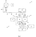
Fig. 2 illustrates a system view of an exemplary embodiment of the solids control system incorporating the vacuum cutting transport system. -
Fig. 3 illustrates a system view of another exemplary embodiment of the solids control system incorporating the vacuum cutting transport system. -
Fig. 4 illustrates an isometric view an exemplary embodiment of a vacuum hub of the continuous vacuum transport system. -
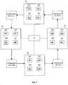
Fig. 5 illustrates a diagram of an exemplary embodiment of a control system of the continuous vacuum transport system. -
Fig. 6 illustrates a flow diagram of an embodiment of a solids control system incorporating a continuous vacuum transport system. - Exemplary embodiments disclosed herein relate to transporting cuttings discharged from a filtration system to a storage area. More specifically, the exemplary embodiments disclosed herein relate to a system and a method of transporting cuttings from an industrial filtration system to a storage area using continuous vacuum and/or continuous pressure. Cuttings, as used herein, refer to the residual portion of a mixture that does not pass through the filter media of a filtration system.
- Referring now to the drawings wherein like numerals refer to like parts,
Fig. 1 generally illustrates an embodiment of asolids control system 10. Thesolids control system 10 may be part of a larger system, such as a drilling system for on-shore oil drilling and/or off-shore oil drilling. However, the disclosed embodiments are not limited to on-shore oil drilling and/or off-shore oil drilling. The disclosed embodiment may be used in conjunction with any system requiring cuttings to be transported. - The
solids control system 10 may have afiltration system 12, a continuousvacuum transport system 14 and/or adischarge collection system 15. Thefiltration system 12 may receive a mixture and may separate the mixture into a cuttings portion and a filtrate portion. Thefiltration system 12 may direct the filtrate portion into a filtrate storage container (17 inFig. 2 ), such as a sump, a pan and/or a reservoir. Further, thefiltration system 12 may direct the cuttings portion to anoutlet 13 of thefiltrate system 13. In an embodiment, thefiltration system 12 may be a shale shaker. In that embodiment, thefiltration system 12 may separate a slurry of drill cuttings and drilling fluid and may output the drill cuttings as the cuttings portion at theoutlet 13. In another embodiment, thefiltration system 12 may be a gyratory sifter. In that embodiment, thefiltration system 12 may separate a mixture of different sized particles. Thefiltration system 12 may output particles that do not pass through a mesh screen as the cuttings portion. As used herein, the term "cuttings portion" will refer to any particulate matter that does not pass through a filtering element, e.g., screen. In other words the "cuttings portion" will refer to a portion that is not a filtrate portion. - As shown in
Fig. 1 , the continuousvacuum transport system 14 may have adischarge manifold 18, avacuum conduit 20, avacuum hub 22, a control system (24 inFig. 2 ), atransport conduit 26 and/or adischarge outlet 28. Thedischarge manifold 18 is in particulate communication with theoutlet 13 of thefiltrate system 12. In other words, thedischarge manifold 18 may receive the cuttings portion from thefiltration system 12. As used herein, the term "in particulate communication with" is used to describe two components such that the cuttings portion is moved from the first component to the second component. - The
discharge manifold 18 connects thevacuum conduit 20 to thefiltrate system 12. A partial vacuum may be applied to thevacuum conduit 20 so that the cuttings portion is drawn from thedischarge manifold 18 though the vacuum conduit 20 into thevacuum hub 22. The cuttings portion may travel through thevacuum hub 22 into thetransport conduit 26. Pressure may be applied to thetransport conduit 26 and may push the cuttings portion from thevacuum hub 22 through thetransport conduit 26 to thedischarge outlet 28. Thedischarge outlet 28 may feed into thedischarge collection system 15. Thedischarge collection system 15 may include acontainer 16. In other embodiments, thecollection system 15 may include a pit, a ship, a cuttings blower, or other collection means known in the art. - The
discharge manifold 18 includes amanifold body 30, amanifold valve 32 and amanifold conduit 34. Themanifold body 30 may have anopening 36 and anexit 38. Further, themanifold body 30 may have a top 40 and a bottom 42. Theopening 36 may be wider than theexit 38 of themanifold body 30. Themanifold body 30 may taper from theopening 36 at the top 40 to theexit 38 at the bottom 42. The cuttings portion from thefiltration system 12 may be deposited into theopening 36 of themanifold body 30. In an embodiment, the cuttings portion from more than onefiltration system 12 may be deposited into theopening 36 of themanifold body 30. The taper of themanifold body 30 may cause the cuttings portion to funnel to theexit 38 of themanifold body 30. - The
manifold valve 32 may be connected to theexit 38 of themanifold body 30. Themanifold valve 32 may also be connected to themanifold conduit 34. Themanifold conduit 34 may connect themanifold valve 32 to thevacuum conduit 20. A vacuum in thevacuum conduit 20 may cause a pressure differential to form at theopening 36 of themanifold body 30. The pressure differential may cause the cuttings portion to pass through themanifold valve 32 and themanifold conduit 34 and may cause the cuttings portion to enter thevacuum conduit 20. Themanifold valve 32 may be shut by the control system 24 (Fig. 2 ) to regulate the movement of the cuttings portion into thevacuum conduit 20. - Referring to
Figs. 1 and2 , a schematic of thesolids control system 10 is shown. Thevacuum transport system 14 includes avacuum conduit 20 having afirst end 44 and asecond end 46. Thefirst end 44 of thevacuum conduit 20 may be connected to themanifold conduit 34 of thedischarge manifold 18. In an embodiment, the continuousvacuum transport system 14 may have a plurality of discharge manifolds 18. As shown inFigs. 1 and3 , a plurality of thefiltration systems 12 may be connected to the plurality of the discharge manifolds 18. The plurality of the discharge manifolds 18 may be connected to thefirst end 44 of thevacuum conduit 20 through themanifold conduit 34 of the discharge manifolds 18. Thesecond end 46 of thevacuum conduit 20 may be connected to thevacuum hub 22. -
Fig. 4 shows a detail view ofvacuum hub 22. Thevacuum hub 22 may have aninlet 48, anoutlet 50, a plurality of holdingtanks 52 and avacuum pump 54. Theinlet 48 of thevacuum hub 22 may be connected to thesecond end 46 of thevacuum conduit 20. Theinlet 48 may also be connected to holdingtanks 52 such that thevacuum conduit 20 is in particulate communication with the holdingtanks 52 via theinlet 48. The plurality of holdingtanks 52 may be connected to theinlet 48 of thevacuum hub 22 and theoutlet 50 of thevacuum hub 22. - The
vacuum hub 22 may have aframe 58 that defines aninterior portion 60 of thevacuum hub 22. The holdingtanks 52 may be located within theinterior portion 60 of theframe 58. Theframe 58 may be configured to accommodate the holdingtanks 52 in different positions. In an embodiment, the holdingtanks 52 may be positioned next to each other on a vertical plane. In another embodiment, one or more of the holdingtanks 52 may be elevated in theframe 58 relative to the rest of the holdingtanks 52. Accordingly, the configuration of the holdingtanks 52 within the frame is not intended to limit the scope of the present disclosure. - Referring to
Figs. 2-4 , each of the plurality of holdingtanks 52 may have apressure vessel 62, aninlet valve 64, anoutlet valve 66 and alevel sensor 68. Thepressure vessel 62 may have a top 70 and a bottom 72. Theinlet valve 64 may be connected to the top 70 of thepressure vessel 62. Furthermore, theinlet valve 64 may be connected to theinlet 48 of thevacuum hub 22. The cuttings portion may travel from thevacuum conduit 20, through theinlet 48 of thevacuum hub 22, through theinlet valve 64 and into thepressure vessel 62 of one of the holdingtanks 52. Thecontrol system 24 may open and/or shut theinlet valves 64 of one or more of the holdingtanks 52 to direct the flow of the cuttings portion. Theoutlet valve 66 may be connected to the bottom 72 of thepressure vessel 62. - The
outlet valve 66 may be connected to theoutlet 50 of thevacuum hub 22. Thecontrol system 24 may open and/or shut theoutlet valves 66 of one or more of the holdingtanks 52 to direct the flow of the cuttings portion. Thelevel sensor 68 may detect the level of the cuttings portion in thepressure vessel 62. In an embodiment, thelevel sensors 68 may communicate to thecontrol system 24 whether thepressure vessels 62 are each empty or full. In another embodiment, thelevel sensors 68 may communicate a value representing an amount of the cuttings portion in each of thepressure vessels 62. - As shown in
Fig. 4 , in an embodiment, each of thepressure vessels 62 may have acylindrical portion 76 and aconical portion 78. Thecylindrical portion 76 may be located at the top 70 of thepressure vessel 62, and theconical portion 78 may be located at the bottom 72 of thepressure vessel 62. Thecylindrical portion 76 and theconical portion 78 may be joined at ajunction point 80. Theconical portion 78 may taper until connecting to theoutlet valve 66. In an embodiment, thepressure vessel 62 may have a plurality oftabs 82 to connect thepressure vessel 62 to theframe 58 of thevacuum hub 22. In a further embodiment, the plurality oftabs 82 may be spaced substantially equally around thejunction point 80 of thepressure vessel 62. - The
pressure vessel 62 may be connected to thevacuum pump 54 of each of the holdingtanks 52. Thevacuum pump 54 may supply a vacuum to the holdingtanks 52 when theinlet valve 64 of the holdingtank 52 is open and theoutlet valve 66 of the holdingtank 52 is closed. The vacuum supplied to the holdingtank 52 by thevacuum pump 54 creates a pressure differential between thefirst end 44 of thevacuum conduit 20 and thepressure vessel 62 of the holdingtank 52. The cuttings portion may flow into the holdingtank 52. Thevacuum pump 54 may supply pressure to the top 70 of thepressure vessel 62 when theoutlet valve 66 of the holdingtank 52 is open and theinlet valve 64 of the holdingtank 52 is closed. The pressure may cause the cuttings portion to flow from the holdingtank 52 though theoutlet valve 66. - As shown in
Fig. 3 , in another embodiment, thevacuum hub 22 may have afirst vacuum pump 54a and asecond vacuum pump 54b to cause the cuttings portion to flow in and out of thepressure vessel 62. Thefirst vacuum pump 54a may supply a vacuum to thepressure vessels 62 when thepressure vessels 62 are filling. Thesecond vacuum pump 54b may supply a pressure to the holdingtanks 52 when thepressure vessels 62 are emptying. - Referring to
Fig. 2 , in an embodiment, thevacuum hub 22 may have apressure tank 56. Thepressure tank 56 may be connected to the top 70 of thepressure vessels 62 of each of the holdingtanks 52. In an embodiment, a plurality of pressure assistconduits 74 may connect thepressure tank 56 to the top 70 of thepressure vessels 62. Thepressure tank 56 may supply pressure to the holdingtank 52 to empty the cuttings portion from the holdingtank 52. Additionally, as illustrated inFig. 4 , thepressure tank 56 may be located within theinterior portion 60 of theframe 58. - Referring to
Figures 1 and4 , thetransport conduit 26 may have afirst end 84 and asecond end 86. Thefirst end 84 of thetransport conduit 26 may be connected to theoutlet 50 of thevacuum hub 22. Thesecond end 86 of thetransport conduit 26 may be connected to thedischarge outlet 28, which is connected to thecollection system 15. During emptying one of the holdingtanks 52, thevacuum pump 54, through theoutlet valve 66 of one of the holdingtanks 52, may supply pressure to thefirst end 84 of thetransport conduit 26 to push the cuttings portion from thefirst end 84 of thetransport conduit 26 to thesecond end 86 of thetransport conduit 26. - Referring to
Figs. 1 and2 , thecontrol system 24 may be connected to themanifold valve 32 of thedischarge manifold 18. Thecontrol system 24 may open and/or close themanifold valve 32 to control the flow of the cuttings portion into thevacuum conduit 20. Additionally, thecontrol system 24 may open and/or may close themanifold valve 32 to control the amount of vacuum pressure that may be used by the continuousvacuum transport system 14 from thevacuum pump 54. Thecontrol system 24 may close themanifold valve 32 of thedischarge manifold 18 when thefiltration system 12 that may be feeding thedischarge manifold 18 is offline. Thecontrol system 24 may also be connected to theinlet valve 64, theoutlet valve 66 and thelevel sensor 68 of each of the holdingtanks 52 of thevacuum hub 22. - To fill one of the holding
tanks 52, thecontrol system 24 may open theinlet valve 64 and may close theoutlet valve 66 of the holdingtank 52. Additionally, to empty one of the holdingtanks 52, thecontrol system 24 may close theinlet valve 64 and may open theoutlet valve 66 of the holdingtank 52. When one of the holdingtanks 52 is not being emptied or filled, thecontrol system 24 may close theinlet valve 64 and theoutlet valve 66 of the holdingtank 52. Thecontrol system 24 may determine whether one or more of the holdingtanks 52 are full or empty by communicating with thelevel sensors 68 of the holdingtanks 52. - The
control system 24 may be a computer system and/or discrete electronic hardware. Additionally, thecontrol system 24 may be autonomous and/or may accept input by a user. In an embodiment, thecontrol system 24 may be located at thevacuum hub 22. In another embodiment, thecontrol system 24 may be located at a central control center. In an embodiment, thecontrol system 24 may be part of a larger system to control the operation of an industrial process, such as a fluids control system in on-shore oil drilling and/or off-shore oil drilling. - In the embodiment shown in
Fig. 2 , thevacuum hub 22 may have two holdingtanks 52. Thecontrol system 24 may cause one of the holdingtanks 52 to fill while causing theother holding tank 52 to empty. The pressure in thetransport conduit 26 and/or vacuum in thevacuum conduit 20 that may be supplied by thevacuum pump 54 may be configured so that the time required to empty one of the holdingtanks 52 is less than or equal to the time required to fill theother holding tank 52. - As illustrated in
Fig. 3 , in another embodiment, thevacuum hub 22 may have three ormore holding tanks 52. Thecontrol system 24 may fill one of the holdingtanks 52 and may empty one of the holdingtanks 52. Additionally, thecontrol system 24 may hold one or more of the holdingtanks 52 so that the holdingtanks 52 are neither filling nor emptying. In this embodiment, thecontrol system 24 may rotate (or change) transportation of the cuttings portion between the holdingtanks 52. - Referring collectively to
Figs. 1-4 , during operation, thedischarge manifold 18 may receive the cuttings portion from thefiltration system 12. Thevacuum pump 54 may cause a pressure differential between thefirst end 44 of thevacuum conduit 20 and thesecond end 46 of thevacuum conduit 20. The cuttings portion may move from thedischarge manifold 18 to the second end of thevacuum conduit 20. In an embodiment with the plurality ofdischarge manifolds 18, the cuttings portion may move from each of the discharge manifolds 18 to thesecond end 46 of thevacuum conduit 20. The cuttings portion may travel from thesecond end 46 of thevacuum conduit 20 into theinlet 48 of thevacuum hub 22. Thecontrol system 24 may control theinlet valves 64 of the holdingtanks 52 to direct the cuttings portion into at least one of the holdingtanks 52. - As shown in
Fig. 5 , thecontrol system 24 may control the holdingtanks tanks tanks control system 24 may assign one of a plurality ofstates tanks state 88a, an emptyingstate 88b, afull state 88c and anempty state 88d. Thecontrol system 24 may manipulate theinlet valve 64 and/oroutlet valve 66 of each of the holdingtanks states state 88a, theinlet valve 64 of the holdingtank 52 may be open, and theoutlet valve 66 of the holdingtank 52 may be closed. In the emptyingstate 88b, theinlet valve 64 of the holdingtank 52 may be closed, and theoutlet valve 66 of the holdingtank 52 may be open. In thefull state 88c and theempty state 88d, theinlet valve 64 of the holdingtank 52 may be closed, and theoutlet valve 66 of the holdingtank 52 may be closed. - Referring to
Figs. 2 and5 , thecontrol system 24 may use thelevel sensors 68 of the holdingtanks 52 to determine when the holdingtanks 52 in the fillingstate 88a is full and may then put the holdingtank 52 in thefull state 88c. When the holdingtank 52 transitions from the fillingstate 88a to thefull state 88c, thecontrol system 24 may select one of the holdingtanks 52 to transition from theempty state 88d to the fillingstate 88a. - Additionally, the
control system 24 may use thelevel sensors 68 of the holdingtanks 52 to determine when one of the holdingtanks 52 in the emptyingstate 88b is empty and may transition the holdingtank 52 into theempty state 88d. When the holdingtank 52 transitions to theempty state 88d from the emptyingstate 88c, thecontrol system 24 may select one of the holdingtanks 52 in thefull state 88c to transition to the emptyingstate 88b. - In an embodiment, the
vacuum hub 22 may have two holdingtanks 52. The holdingtanks 52 may transition between the fillingstate 88a and the emptyingstate 88b. In an embodiment, thevacuum hub 22 may have more than two of the holdingtanks 52. Thecontrol system 24 may rotate which of the holdingtanks 52 is placed in the fillingstate 88a and which of the holdingtanks 52 is placed in the emptyingstate 88b. In this embodiment, the holdingtanks 52 may transition into theempty state 88d between the emptyingstate 88b and the fillingstate 88a. - Referring now to
Fig. 6 , a flow diagram illustrates an embodiment of the solids control system incorporating a continuous vacuum transport system.Fig. 6 illustrates flows and connectivity between the holdingtanks vacuum hub 22. For example, acuttings portion flow 90 is shown with directional arrows to indicate direction of travel of the cuttings portion. Apressure flow 91 is shown with directional arrows to indicate the application of pressure to the holdingtanks 52. Further, avacuum flow 92 is shown with directional arrows to indicate the application of vacuum to the holdingtanks 52. Thepressure flow 91 may be controlled and/or directed by valves 94. The valves 94 may be connected in thepressure flow 91 to the holdingtanks control system 24. Thevacuum flow 92 may be controlled and/or directed by valves 93. The valves 93 may be connected in thevacuum flow 92 to the holdingtanks control system 24. - The
cuttings portion flow 90 may supply the cuttings portion to the holdingtanks 52 of thevacuum hub 22. Thevalves 64 may be connected in the supply of thecuttings portion flow 90 to the holdingtanks valves 64 may be controlled by thecontrol system 24. Thevalves 66 may be connected at the bottom 72 of the holdingtanks valves 66 may be connected in the discharge of the cuttings portion flow 90 from the holdingtanks outlet 50 of thevacuum hub 22. For example, as shown inFig. 6 , the directional arrows of thecuttings portion flow 90 indicate travel of the supply of the cuttings portion from right to left. Conversely, the directional arrows of thecuttings portion flow 90 indicate travel of the discharge of the cuttings portion from left to right. - Referring to
Figs. 1 and6 , the cuttings portion may be drawn from thedischarge manifold 18 though thevacuum conduit 20 into thevacuum hub 22. The cuttings portion may enter through theinlet 48 of thevacuum hub 22 as shown inFig. 4 . The cuttings portion may travel into one of the holdingtanks vacuum hub 22. -
Fig. 6 also illustrates air bypass lines 95. The air bypass lines 95 may connect each holdingtank 52 to another holdingtank 52. In some embodiments, the air bypass lines 95 may connect each holdingtank 52 to anadjacent holding tank 52. The air bypass lines 95 may have valves 96. The valves 96 may be controlled by thecontrol system 24. For example,air bypass line 95a may be connected at the top 70 of holdingtank 52a and at the top 70 of holdingtank 52b to allow air flow betweenholding tank 52a andholding tank 52b. Also,air bypass line 95b may be connected at the top 70 of holdingtank 52b and at the top 70 of holdingtank 52c to allow airflow betweenholding tank 52b and holdingtank 52c. Further,air bypass line 95c may be connected at the top 70 of holdingtank 52c to the top 70 of holdingtank 52d to allow airflow between holdingtank 52c andholding tank 52d. Finally,air bypass line 95d may be connected at the top 70 of holdingtank 52d to the top 70 of holdingtank 52a to allow air flow betweenholding tank 52d andholding tank 52a. Theair bypass lines valves control system 24. - The cuttings portion of the
cuttings portion flow 90 may begin flowing into holdingtank 52a. The supply of the cuttings portion may enter theholding tank 52a when thevalve 64a is open and thevalve 66a at the bottom 72 of theholding tank 52a is closed. Thus, the cuttings portion may accumulate in theholding tank 52a and may fill theholding tank 52a. To facilitate thecuttings portion flow 90 of the cuttings portion into theholding tank 52a, a vacuum may be applied to theholding tank 52a. For example, the vacuum may be provided by thevacuum flow 92 when thevalve 93b andvalve 96a in theair bypass line 95a is also open. The vacuum may create suction within theholding tank 52a to draw the cuttings portion into theholding tank 52a as shown. - Referring again to
Fig. 6 , theholding tank 52d may discharge the cuttings portion through thevalve 66d into the discharge of thecuttings portion flow 90. To facilitate thecuttings portion flow 90 of the cuttings portion out of theholding tank 52d, a pressure may be applied to theholding tank 52d. For example, the pressure may be provided by thepressure flow 91 when thevalve 94d is open. The pressure may force the cuttings portion out of theholding tank 52d and into the discharge of thecuttings portion flow 90 as shown. Thus, the cuttings portion may move from theholding tank 52d, through thevalve 66d to theoutlet 50 of thevacuum hub 22. - As shown in
Figs. 5 and6 , thecontrol system 24 may control the holdingtanks tanks tanks control system 24 may rotate which of the holdingtanks 52 is placed in the filling state and which of the holdingtanks 52 is placed in the emptying state. -
Fig. 6 illustrates a particular state of the holdingtanks 52. For example, theholding tank 52a may be described as the suction tank. Thecuttings portion flow 90 may be entering theholding tank 52a placing theholding tank 52a in the filling state. Theholding tank 52b may be described as the ready tank to become the next in succession to be placed in the filling state. The holdingtank 52c may be in an empty state. Theholding tank 52d may be described as the discharge tank. Thecuttings portion flow 90 may be discharging from theholding tank 52d placing theholding tank 52d in the emptying state. - During operation of the
control system 24, thevacuum flow 92 may pull air from theholding tank 52b with thevalve 96a of theair bypass line 95a open. As a result, the vacuum in theholding tank 52a may be transferred to theholding tank 52b and the cuttings portion may enter theholding tank 52b. This operation may prevent the cutting portion from entering in thevacuum flow 92 which may cause vacuum pump damage. - When the
control system 24 may detect that theholding tank 52a may be full (e.g. based on level sensor 68), the process shifts, so that: 1) the discharge tank, theholding tank 52d, may become the empty tank; 2) the empty tank, the holdingtank 52c may become the ready tank; 3) the ready tank, theholding tank 52b may become the suction tank; and 4) the suction tank, theholding tank 52a, may become the discharge tank. - Typically, a constraint on the
control system 24 may be that the discharging process for aparticular holding tank 52 may be completed before the filling process of another holdingtank 52 may be initiated. Upon completion of the discharging process of a particular holding tank may be empty, the valve that connects the empty tank to thevacuum flow 92 may open so that thecontrol system 24 may start evacuating the tank and have the tank ready for the process shift. The flow of the cuttings portion from thefiltration system 12 through the continuousvacuum transport system 14 to thevacuum hub 22 may be continuous. The vacuum in the manifold and vacuum conduit may be continuously applied. - The cuttings portion may move from one of the holding
tanks outlet 50 of thevacuum hub 22. Thevacuum pump 54 may provide pressure to transport the discharge from theoutlet 50 of thevacuum hub 22 through thetransport conduit 26 to thedischarge outlet 28. At thedischarge outlet 28, the discharge may be collected in acontainer 16 ofcollection system 15. In an embodiment, thecollection system 15 may include, for example, but not limited to a cuttings blower to transport the discharge further to a container, a pit, or a ship. - A solids control system according to embodiments disclosed herein may include a filtration system that produces a cuttings portion and a filtrate portion, a vacuum transport system, and a collection system connected to the vacuum transport system. The vacuum transport system may include a discharge manifold connected to the filtration system. The discharge manifold may also be connected to a vacuum conduit. The vacuum conduit may be connected to a vacuum hub, which is connected to a transport conduit. The transport conduit may be connected to the collection system.
- A method in accordance with embodiments disclosed herein may include separating a mixture into a filtrate portion and a cuttings portion. A partial vacuum may be applied to a vacuum conduit, thereby drawing the cuttings portion into the vacuum conduit. A first holding tank may be filled with the cuttings portion from the vacuum by applying a vacuum to the first holding tank in particulate communication with the vacuum conduit. The first holding tank may be emptied of the cuttings portion to a transport conduit by applying pressure to a top of the holding tank. The cuttings portion may then be directed into a storage vessel.
- A vacuum transport system in accordance with embodiments disclosed herein may include a vacuum conduit connected to a vacuum hub. Specifically, an inlet of the vacuum hub may be in particulate communication with the vacuum conduit. The vacuum hub may include a plurality of holding tanks in particulate communication with the inlet of the vacuum hub. An outlet of the vacuum hub may be in particulate communication with the holding tank and a transport conduit.
- While the present disclosure has been described with respect to a limited number of embodiments, those skilled in the art, having benefit of this disclosure, will appreciate that other embodiments may be devised which do not depart from the scope of the disclosure as described herein. Accordingly, the scope of the present disclosure should be limited only by the attached claims.
Claims (15)
- A system comprising:a filtration system (12) that produces a cuttings portion and a filtrate portion;a vacuum transport system for transporting the cuttings portion from the filtration system comprising:a discharge manifold (18) connected to an outlet (13) of the filtration system, the discharge manifold having a manifold body (30) with a top (40) and a bottom (42), an opening (36) at the top and an exit (38) at the bottom;a manifold valve (32) connected to the exit of the manifold body;a vacuum conduit (20) connected to the manifold valve, the discharge manifold (18) and manifold valve connecting the vacuum conduit (20) to the filtration system (12),a vacuum hub (22) connected to the vacuum conduit;a transport conduit (26) connected to the vacuum hub; anda collection system (15) connected to the transport conduit of the vacuum transport system, characterized in thatthe manifold valve may be shut by a control system (24) to regulate movement of the cuttings portion into the vacuum conduit.
- The system of claim 1, wherein the vacuum hub comprises:an inlet (48) in particulate communication with the vacuum conduit;at least one holding tank (52) in particulate communication with the inlet;a vacuum pump (54) operatively coupled to the at least one holding tank; andan outlet (50) in particulate communication with the holding tank.
- The system of claim 2, wherein the at least one holding tank comprises:a pressure vessel (62);a pressure vessel inlet valve (64) located at a top of the pressure vessel; anda pressure vessel outlet valve (66) located at a bottom of the pressure vessel.
- The system of claim 1, wherein the control system (24) is operatively coupled to the vacuum hub; and/or further comprising a fill sensor (68) operatively coupled to a pressure vessel of the vacuum hub.
- The system of claim 1, wherein the vacuum hub comprises:an inlet (48) connected to the vacuum conduit;a plurality of holding tanks (52) connected to the inlet, each holding tank having an inlet valve (64) and an outlet valve (66);a vacuum pump (54) operatively coupled to each of the plurality of holding tanks;an outlet (50) in particulate communication with the holding tank; andthe control system (24), being operatively coupled to the tank inlet valve, the tank outlet valve, and the vacuum pump, wherein the control system is configured to selectively open and close the tank inlet and outlet valves to supply a vacuum.
- A system according to claim 1, further comprising:an inlet (48) of the vacuum hub in particulate communication with the vacuum conduit;a plurality of holding tanks (52) in particulate communication with the inlet of the vacuum hub;an outlet (50) of the vacuum hub in particulate communication with the holding tank; andthe transport conduit in particulate communication with the outlet of the vacuum hub.
- The system of claim 6, further comprising an air bypass line (95) disposed between at least a first and second holding tank to provide fluid communication between the adjacent holding tanks; and/or
further comprising two vacuum pumps coupled to each holding tank, wherein a first vacuum pump provides a vacuum while filling a first holding tank and a second vacuum pump provides a vacuum while emptying the first holding tank. - A method comprising:separating, via a filtration system (12), a mixture into a filtrate portion and a cuttings portion;receiving, at a discharge manifold (18), the cuttings portion from an outlet (13) of the filtration system that is in particulate communication with the discharge manifold;applying a partial vacuum to a vacuum conduit (20), thereby drawing the cuttings portion from the discharge manifold into the vacuum conduit;connecting a manifold valve (32) to an exit of the discharge manifold, wherein the discharge manifold and manifold valve connect the vacuum conduit and the filtration system, wherein the manifold may be shut by a control system (24) to a closed position to regulate movement of the cuttings portion into the vacuum conduit;filling a first holding tank (52) with the cuttings portion from the vacuum conduit by applying a vacuum to the first holding tank in particulate communication with the vacuum conduit; andemptying the cuttings portion in the first holding tank to a transport conduit (26) by applying pressure to a top of the holding tank; anddirecting the cuttings portion into a storage vessel.
- The method of claim 8, further comprising depositing the cuttings portion into a discharge manifold (18), wherein the discharge manifold is in particulate communication with the vacuum conduit.
- The method of claim 8 or 9, further comprising opening a valve (64) disposed between the vacuum conduit and the holding tank to allow the first holding tank to fill; and/or further comprising closing a valve (64) disposed between the vacuum conduit and the holding tank to allow the first holding tank to empty.
- The method of claim 8, further comprising changing a first state of the first holding tank from at least one of a filling state, a emptying state, a full state, or an empty state, to a second state different from the first state, with the control system (24) operatively coupled to an inlet and outlet valve of the first holding tank.
- The method of any one of claims 8 to 11, further comprising emptying the cuttings portion from the first holding tank when a level sensor (68) signals the control system (24) that the first tank is full.
- The method of any one of claims 8 to 12, further comprising monitoring the first holding tank with the control system (24); and/or
further comprising filling the first holding tank while emptying a second holding tank (52). - The method of any one of claims 8 to 13, further comprising maintaining a continuous vacuum on the vacuum conduit.
- The method of any one of claims 8 to 14, further comprising:opening an air bypass valve (96a) between the first holding tank and a second holding tank;transferring the vacuum from the first holding tank to the second holding tank once the first holding tank is full; anddrawing the cuttings portion into the second holding tank, thereby preventing the cuttings portion from entering the vacuum flow.
Applications Claiming Priority (2)
| Application Number | Priority Date | Filing Date | Title |
|---|---|---|---|
| US201361909170P | 2013-11-26 | 2013-11-26 | |
| PCT/US2014/067554 WO2015081162A1 (en) | 2013-11-26 | 2014-11-26 | Continuous vacuum transport system and method |
Publications (3)
| Publication Number | Publication Date |
|---|---|
| EP3074587A1 EP3074587A1 (en) | 2016-10-05 |
| EP3074587A4 EP3074587A4 (en) | 2017-08-02 |
| EP3074587B1 true EP3074587B1 (en) | 2020-03-18 |
Family
ID=53199626
Family Applications (1)
| Application Number | Title | Priority Date | Filing Date |
|---|---|---|---|
| EP14866176.2A Active EP3074587B1 (en) | 2013-11-26 | 2014-11-26 | Continuous vacuum transport system and method |
Country Status (5)
| Country | Link |
|---|---|
| US (1) | US10358882B2 (en) |
| EP (1) | EP3074587B1 (en) |
| JP (1) | JP6681330B2 (en) |
| MX (1) | MX2016006871A (en) |
| WO (1) | WO2015081162A1 (en) |
Citations (1)
| Publication number | Priority date | Publication date | Assignee | Title |
|---|---|---|---|---|
| US20110147087A1 (en) * | 2008-05-15 | 2011-06-23 | M-I L.L.C. | Cuttings transfer system |
Family Cites Families (15)
| Publication number | Priority date | Publication date | Assignee | Title |
|---|---|---|---|---|
| US4085975A (en) * | 1976-07-29 | 1978-04-25 | Dundee Cement Company | Aerating barge unloading system |
| US4695205A (en) * | 1985-12-20 | 1987-09-22 | United Dc | Pneumatic conveying system |
| US6179071B1 (en) * | 1994-02-17 | 2001-01-30 | M-I L.L.C. | Method and apparatus for handling and disposal of oil and gas well drill cuttings |
| US6345672B1 (en) * | 1994-02-17 | 2002-02-12 | Gary Dietzen | Method and apparatus for handling and disposal of oil and gas well drill cuttings |
| JP3051326B2 (en) * | 1995-08-30 | 2000-06-12 | 株式会社 東京ピア | High-speed mud separation equipment |
| JPH09206759A (en) * | 1996-01-31 | 1997-08-12 | Kajima Corp | Muddy water and muddy water treatment method |
| GB9913909D0 (en) * | 1999-06-16 | 1999-08-18 | Clyde Pneumatic Conveying Limi | Pneumatic conveying |
| WO2004083597A1 (en) * | 2003-03-19 | 2004-09-30 | Varco I/P, Inc. | Apparatus and method for moving drilled cuttings |
| US7493969B2 (en) * | 2003-03-19 | 2009-02-24 | Varco I/P, Inc. | Drill cuttings conveyance systems and methods |
| US7207399B2 (en) * | 2004-10-04 | 2007-04-24 | M-L L.L.C. | Modular pressure control and drilling waste management apparatus for subterranean borehole operations |
| US7753126B2 (en) * | 2005-11-26 | 2010-07-13 | Reddoch Sr Jeffrey A | Method and apparatus for vacuum collecting and gravity depositing drill cuttings |
| US7514005B2 (en) | 2006-01-26 | 2009-04-07 | M-I L.L.C. | Method of processing drilling fluid |
| US8083935B2 (en) * | 2007-01-31 | 2011-12-27 | M-I Llc | Cuttings vessels for recycling oil based mud and water |
| WO2011140635A2 (en) | 2010-05-12 | 2011-11-17 | Daniel Guy Pomerleau | Systems and methods for drying drill cuttings |
| WO2015192245A1 (en) * | 2014-06-20 | 2015-12-23 | Fp Marangoni Inc. | Gravity induced separation of gases and fluids in a vacuum-based drilling fluid recovery system |
-
2014
- 2014-11-26 US US15/038,960 patent/US10358882B2/en active Active
- 2014-11-26 JP JP2016535154A patent/JP6681330B2/en active Active
- 2014-11-26 MX MX2016006871A patent/MX2016006871A/en active IP Right Grant
- 2014-11-26 WO PCT/US2014/067554 patent/WO2015081162A1/en not_active Ceased
- 2014-11-26 EP EP14866176.2A patent/EP3074587B1/en active Active
Patent Citations (1)
| Publication number | Priority date | Publication date | Assignee | Title |
|---|---|---|---|---|
| US20110147087A1 (en) * | 2008-05-15 | 2011-06-23 | M-I L.L.C. | Cuttings transfer system |
Also Published As
| Publication number | Publication date |
|---|---|
| EP3074587A4 (en) | 2017-08-02 |
| MX2016006871A (en) | 2017-01-11 |
| US10358882B2 (en) | 2019-07-23 |
| JP6681330B2 (en) | 2020-04-15 |
| WO2015081162A1 (en) | 2015-06-04 |
| JP2016539261A (en) | 2016-12-15 |
| EP3074587A1 (en) | 2016-10-05 |
| US20170022770A1 (en) | 2017-01-26 |
Similar Documents
| Publication | Publication Date | Title |
|---|---|---|
| EP2113050B1 (en) | Cuttings processing system | |
| EP1928769B1 (en) | Apparatus and method for conveying drill cuttings | |
| US8083935B2 (en) | Cuttings vessels for recycling oil based mud and water | |
| US6988567B2 (en) | Drilled cuttings movement systems and methods | |
| EP2481881A2 (en) | Vacuum assisted drill cuttings dryer and handling apparatus | |
| EA021969B1 (en) | System and method for proppant transfer | |
| EP2052127A1 (en) | Method and apparatus for preparing drill cuttings for reinjection into a well | |
| US20140246054A1 (en) | Use of cuttings vessel for tank cleaning | |
| WO2004083597A1 (en) | Apparatus and method for moving drilled cuttings | |
| NO327942B1 (en) | Device for pneumatic transmission of cuttings over a platform on an oil rig. | |
| EP2480748B1 (en) | Multiple process service vessel | |
| WO2007070150A3 (en) | Drill cuttings transfer system and related methods | |
| US20170291779A1 (en) | Dust control in pneumatic particulate handling applications | |
| US20030106713A1 (en) | Proppant recovery system | |
| CN106014306B (en) | Drilling well waste disposal system and method | |
| NO343443B1 (en) | MODULAR DRILLING SYSTEM AND METHOD OF USING IT | |
| US10358882B2 (en) | Continuous vacuum transport system and method | |
| WO2004005673A1 (en) | Sand transport system | |
| US20080128173A1 (en) | Drill Cuttings Transfer System and Related Methods | |
| RU2405731C2 (en) | Method and system of drilling slime transfer | |
| EP1603817B1 (en) | Apparatus and method for transferring settled or suspended solids from an open vessel into a closed vessel | |
| US20240359121A1 (en) | Dual inlet cyclonic separation apparatus for processing flowback from wellsite | |
| US9689218B1 (en) | Drill cuttings diverter system | |
| US20250163675A1 (en) | Floating Filtering Apparatus And Dredging System Therewith | |
| JPH0663260B2 (en) | Tank switching method in mud pressure feeder |
Legal Events
| Date | Code | Title | Description |
|---|---|---|---|
| PUAI | Public reference made under article 153(3) epc to a published international application that has entered the european phase |
Free format text: ORIGINAL CODE: 0009012 |
|
| 17P | Request for examination filed |
Effective date: 20160526 |
|
| AK | Designated contracting states |
Kind code of ref document: A1 Designated state(s): AL AT BE BG CH CY CZ DE DK EE ES FI FR GB GR HR HU IE IS IT LI LT LU LV MC MK MT NL NO PL PT RO RS SE SI SK SM TR |
|
| AX | Request for extension of the european patent |
Extension state: BA ME |
|
| DAX | Request for extension of the european patent (deleted) | ||
| A4 | Supplementary search report drawn up and despatched |
Effective date: 20170704 |
|
| RIC1 | Information provided on ipc code assigned before grant |
Ipc: B65G 53/24 20060101ALI20170628BHEP Ipc: E21B 21/06 20060101AFI20170628BHEP Ipc: E21B 43/02 20060101ALI20170628BHEP |
|
| STAA | Information on the status of an ep patent application or granted ep patent |
Free format text: STATUS: EXAMINATION IS IN PROGRESS |
|
| 17Q | First examination report despatched |
Effective date: 20180817 |
|
| GRAP | Despatch of communication of intention to grant a patent |
Free format text: ORIGINAL CODE: EPIDOSNIGR1 |
|
| STAA | Information on the status of an ep patent application or granted ep patent |
Free format text: STATUS: GRANT OF PATENT IS INTENDED |
|
| INTG | Intention to grant announced |
Effective date: 20191017 |
|
| RAP1 | Party data changed (applicant data changed or rights of an application transferred) |
Owner name: M-I L.L.C. Owner name: MANTOVANI & VICENTINI S.R.L. |
|
| RIN1 | Information on inventor provided before grant (corrected) |
Inventor name: BERGONZONI, MARCO Inventor name: VICENTINI, LEONARDO RENZO |
|
| GRAS | Grant fee paid |
Free format text: ORIGINAL CODE: EPIDOSNIGR3 |
|
| GRAA | (expected) grant |
Free format text: ORIGINAL CODE: 0009210 |
|
| STAA | Information on the status of an ep patent application or granted ep patent |
Free format text: STATUS: THE PATENT HAS BEEN GRANTED |
|
| AK | Designated contracting states |
Kind code of ref document: B1 Designated state(s): AL AT BE BG CH CY CZ DE DK EE ES FI FR GB GR HR HU IE IS IT LI LT LU LV MC MK MT NL NO PL PT RO RS SE SI SK SM TR |
|
| REG | Reference to a national code |
Ref country code: GB Ref legal event code: FG4D |
|
| REG | Reference to a national code |
Ref country code: DE Ref legal event code: R096 Ref document number: 602014062677 Country of ref document: DE |
|
| REG | Reference to a national code |
Ref country code: AT Ref legal event code: REF Ref document number: 1246088 Country of ref document: AT Kind code of ref document: T Effective date: 20200415 Ref country code: IE Ref legal event code: FG4D |
|
| PG25 | Lapsed in a contracting state [announced via postgrant information from national office to epo] |
Ref country code: NO Free format text: LAPSE BECAUSE OF FAILURE TO SUBMIT A TRANSLATION OF THE DESCRIPTION OR TO PAY THE FEE WITHIN THE PRESCRIBED TIME-LIMIT Effective date: 20200618 Ref country code: FI Free format text: LAPSE BECAUSE OF FAILURE TO SUBMIT A TRANSLATION OF THE DESCRIPTION OR TO PAY THE FEE WITHIN THE PRESCRIBED TIME-LIMIT Effective date: 20200318 Ref country code: RS Free format text: LAPSE BECAUSE OF FAILURE TO SUBMIT A TRANSLATION OF THE DESCRIPTION OR TO PAY THE FEE WITHIN THE PRESCRIBED TIME-LIMIT Effective date: 20200318 |
|
| REG | Reference to a national code |
Ref country code: NL Ref legal event code: MP Effective date: 20200318 |
|
| PG25 | Lapsed in a contracting state [announced via postgrant information from national office to epo] |
Ref country code: SE Free format text: LAPSE BECAUSE OF FAILURE TO SUBMIT A TRANSLATION OF THE DESCRIPTION OR TO PAY THE FEE WITHIN THE PRESCRIBED TIME-LIMIT Effective date: 20200318 Ref country code: LV Free format text: LAPSE BECAUSE OF FAILURE TO SUBMIT A TRANSLATION OF THE DESCRIPTION OR TO PAY THE FEE WITHIN THE PRESCRIBED TIME-LIMIT Effective date: 20200318 Ref country code: HR Free format text: LAPSE BECAUSE OF FAILURE TO SUBMIT A TRANSLATION OF THE DESCRIPTION OR TO PAY THE FEE WITHIN THE PRESCRIBED TIME-LIMIT Effective date: 20200318 Ref country code: GR Free format text: LAPSE BECAUSE OF FAILURE TO SUBMIT A TRANSLATION OF THE DESCRIPTION OR TO PAY THE FEE WITHIN THE PRESCRIBED TIME-LIMIT Effective date: 20200619 Ref country code: BG Free format text: LAPSE BECAUSE OF FAILURE TO SUBMIT A TRANSLATION OF THE DESCRIPTION OR TO PAY THE FEE WITHIN THE PRESCRIBED TIME-LIMIT Effective date: 20200618 |
|
| REG | Reference to a national code |
Ref country code: LT Ref legal event code: MG4D |
|
| PG25 | Lapsed in a contracting state [announced via postgrant information from national office to epo] |
Ref country code: NL Free format text: LAPSE BECAUSE OF FAILURE TO SUBMIT A TRANSLATION OF THE DESCRIPTION OR TO PAY THE FEE WITHIN THE PRESCRIBED TIME-LIMIT Effective date: 20200318 |
|
| PG25 | Lapsed in a contracting state [announced via postgrant information from national office to epo] |
Ref country code: SK Free format text: LAPSE BECAUSE OF FAILURE TO SUBMIT A TRANSLATION OF THE DESCRIPTION OR TO PAY THE FEE WITHIN THE PRESCRIBED TIME-LIMIT Effective date: 20200318 Ref country code: SM Free format text: LAPSE BECAUSE OF FAILURE TO SUBMIT A TRANSLATION OF THE DESCRIPTION OR TO PAY THE FEE WITHIN THE PRESCRIBED TIME-LIMIT Effective date: 20200318 Ref country code: EE Free format text: LAPSE BECAUSE OF FAILURE TO SUBMIT A TRANSLATION OF THE DESCRIPTION OR TO PAY THE FEE WITHIN THE PRESCRIBED TIME-LIMIT Effective date: 20200318 Ref country code: PT Free format text: LAPSE BECAUSE OF FAILURE TO SUBMIT A TRANSLATION OF THE DESCRIPTION OR TO PAY THE FEE WITHIN THE PRESCRIBED TIME-LIMIT Effective date: 20200812 Ref country code: LT Free format text: LAPSE BECAUSE OF FAILURE TO SUBMIT A TRANSLATION OF THE DESCRIPTION OR TO PAY THE FEE WITHIN THE PRESCRIBED TIME-LIMIT Effective date: 20200318 Ref country code: CZ Free format text: LAPSE BECAUSE OF FAILURE TO SUBMIT A TRANSLATION OF THE DESCRIPTION OR TO PAY THE FEE WITHIN THE PRESCRIBED TIME-LIMIT Effective date: 20200318 Ref country code: RO Free format text: LAPSE BECAUSE OF FAILURE TO SUBMIT A TRANSLATION OF THE DESCRIPTION OR TO PAY THE FEE WITHIN THE PRESCRIBED TIME-LIMIT Effective date: 20200318 Ref country code: IS Free format text: LAPSE BECAUSE OF FAILURE TO SUBMIT A TRANSLATION OF THE DESCRIPTION OR TO PAY THE FEE WITHIN THE PRESCRIBED TIME-LIMIT Effective date: 20200718 |
|
| REG | Reference to a national code |
Ref country code: AT Ref legal event code: MK05 Ref document number: 1246088 Country of ref document: AT Kind code of ref document: T Effective date: 20200318 |
|
| REG | Reference to a national code |
Ref country code: DE Ref legal event code: R097 Ref document number: 602014062677 Country of ref document: DE |
|
| PLBE | No opposition filed within time limit |
Free format text: ORIGINAL CODE: 0009261 |
|
| STAA | Information on the status of an ep patent application or granted ep patent |
Free format text: STATUS: NO OPPOSITION FILED WITHIN TIME LIMIT |
|
| PG25 | Lapsed in a contracting state [announced via postgrant information from national office to epo] |
Ref country code: ES Free format text: LAPSE BECAUSE OF FAILURE TO SUBMIT A TRANSLATION OF THE DESCRIPTION OR TO PAY THE FEE WITHIN THE PRESCRIBED TIME-LIMIT Effective date: 20200318 Ref country code: AT Free format text: LAPSE BECAUSE OF FAILURE TO SUBMIT A TRANSLATION OF THE DESCRIPTION OR TO PAY THE FEE WITHIN THE PRESCRIBED TIME-LIMIT Effective date: 20200318 Ref country code: IT Free format text: LAPSE BECAUSE OF FAILURE TO SUBMIT A TRANSLATION OF THE DESCRIPTION OR TO PAY THE FEE WITHIN THE PRESCRIBED TIME-LIMIT Effective date: 20200318 Ref country code: DK Free format text: LAPSE BECAUSE OF FAILURE TO SUBMIT A TRANSLATION OF THE DESCRIPTION OR TO PAY THE FEE WITHIN THE PRESCRIBED TIME-LIMIT Effective date: 20200318 |
|
| 26N | No opposition filed |
Effective date: 20201221 |
|
| PG25 | Lapsed in a contracting state [announced via postgrant information from national office to epo] |
Ref country code: PL Free format text: LAPSE BECAUSE OF FAILURE TO SUBMIT A TRANSLATION OF THE DESCRIPTION OR TO PAY THE FEE WITHIN THE PRESCRIBED TIME-LIMIT Effective date: 20200318 |
|
| PG25 | Lapsed in a contracting state [announced via postgrant information from national office to epo] |
Ref country code: SI Free format text: LAPSE BECAUSE OF FAILURE TO SUBMIT A TRANSLATION OF THE DESCRIPTION OR TO PAY THE FEE WITHIN THE PRESCRIBED TIME-LIMIT Effective date: 20200318 |
|
| REG | Reference to a national code |
Ref country code: DE Ref legal event code: R119 Ref document number: 602014062677 Country of ref document: DE |
|
| PG25 | Lapsed in a contracting state [announced via postgrant information from national office to epo] |
Ref country code: MC Free format text: LAPSE BECAUSE OF FAILURE TO SUBMIT A TRANSLATION OF THE DESCRIPTION OR TO PAY THE FEE WITHIN THE PRESCRIBED TIME-LIMIT Effective date: 20200318 |
|
| REG | Reference to a national code |
Ref country code: CH Ref legal event code: PL |
|
| GBPC | Gb: european patent ceased through non-payment of renewal fee |
Effective date: 20201126 |
|
| PG25 | Lapsed in a contracting state [announced via postgrant information from national office to epo] |
Ref country code: LU Free format text: LAPSE BECAUSE OF NON-PAYMENT OF DUE FEES Effective date: 20201126 |
|
| REG | Reference to a national code |
Ref country code: BE Ref legal event code: MM Effective date: 20201130 |
|
| PG25 | Lapsed in a contracting state [announced via postgrant information from national office to epo] |
Ref country code: LI Free format text: LAPSE BECAUSE OF NON-PAYMENT OF DUE FEES Effective date: 20201130 Ref country code: CH Free format text: LAPSE BECAUSE OF NON-PAYMENT OF DUE FEES Effective date: 20201130 |
|
| PG25 | Lapsed in a contracting state [announced via postgrant information from national office to epo] |
Ref country code: IE Free format text: LAPSE BECAUSE OF NON-PAYMENT OF DUE FEES Effective date: 20201126 Ref country code: FR Free format text: LAPSE BECAUSE OF NON-PAYMENT OF DUE FEES Effective date: 20201130 |
|
| PG25 | Lapsed in a contracting state [announced via postgrant information from national office to epo] |
Ref country code: DE Free format text: LAPSE BECAUSE OF NON-PAYMENT OF DUE FEES Effective date: 20210601 Ref country code: GB Free format text: LAPSE BECAUSE OF NON-PAYMENT OF DUE FEES Effective date: 20201126 |
|
| PG25 | Lapsed in a contracting state [announced via postgrant information from national office to epo] |
Ref country code: TR Free format text: LAPSE BECAUSE OF FAILURE TO SUBMIT A TRANSLATION OF THE DESCRIPTION OR TO PAY THE FEE WITHIN THE PRESCRIBED TIME-LIMIT Effective date: 20200318 Ref country code: MT Free format text: LAPSE BECAUSE OF FAILURE TO SUBMIT A TRANSLATION OF THE DESCRIPTION OR TO PAY THE FEE WITHIN THE PRESCRIBED TIME-LIMIT Effective date: 20200318 Ref country code: CY Free format text: LAPSE BECAUSE OF FAILURE TO SUBMIT A TRANSLATION OF THE DESCRIPTION OR TO PAY THE FEE WITHIN THE PRESCRIBED TIME-LIMIT Effective date: 20200318 |
|
| PG25 | Lapsed in a contracting state [announced via postgrant information from national office to epo] |
Ref country code: MK Free format text: LAPSE BECAUSE OF FAILURE TO SUBMIT A TRANSLATION OF THE DESCRIPTION OR TO PAY THE FEE WITHIN THE PRESCRIBED TIME-LIMIT Effective date: 20200318 Ref country code: AL Free format text: LAPSE BECAUSE OF FAILURE TO SUBMIT A TRANSLATION OF THE DESCRIPTION OR TO PAY THE FEE WITHIN THE PRESCRIBED TIME-LIMIT Effective date: 20200318 |
|
| PG25 | Lapsed in a contracting state [announced via postgrant information from national office to epo] |
Ref country code: BE Free format text: LAPSE BECAUSE OF NON-PAYMENT OF DUE FEES Effective date: 20201130 |
|
| PG25 | Lapsed in a contracting state [announced via postgrant information from national office to epo] |
Ref country code: IS Free format text: LAPSE BECAUSE OF NON-PAYMENT OF DUE FEES Effective date: 20200718 |