EP3073524A1 - High thermal conductivity joint utilizing continuous aligned carbon nanotubes - Google Patents
High thermal conductivity joint utilizing continuous aligned carbon nanotubes Download PDFInfo
- Publication number
- EP3073524A1 EP3073524A1 EP16157009.8A EP16157009A EP3073524A1 EP 3073524 A1 EP3073524 A1 EP 3073524A1 EP 16157009 A EP16157009 A EP 16157009A EP 3073524 A1 EP3073524 A1 EP 3073524A1
- Authority
- EP
- European Patent Office
- Prior art keywords
- heat
- sheet
- pipe
- face
- cnts
- Prior art date
- Legal status (The legal status is an assumption and is not a legal conclusion. Google has not performed a legal analysis and makes no representation as to the accuracy of the status listed.)
- Granted
Links
Images




Classifications
-
- H—ELECTRICITY
- H05—ELECTRIC TECHNIQUES NOT OTHERWISE PROVIDED FOR
- H05K—PRINTED CIRCUITS; CASINGS OR CONSTRUCTIONAL DETAILS OF ELECTRIC APPARATUS; MANUFACTURE OF ASSEMBLAGES OF ELECTRICAL COMPONENTS
- H05K7/00—Constructional details common to different types of electric apparatus
- H05K7/20—Modifications to facilitate cooling, ventilating, or heating
- H05K7/2029—Modifications to facilitate cooling, ventilating, or heating using a liquid coolant with phase change in electronic enclosures
- H05K7/20336—Heat pipes, e.g. wicks or capillary pumps
-
- H—ELECTRICITY
- H05—ELECTRIC TECHNIQUES NOT OTHERWISE PROVIDED FOR
- H05K—PRINTED CIRCUITS; CASINGS OR CONSTRUCTIONAL DETAILS OF ELECTRIC APPARATUS; MANUFACTURE OF ASSEMBLAGES OF ELECTRICAL COMPONENTS
- H05K7/00—Constructional details common to different types of electric apparatus
- H05K7/20—Modifications to facilitate cooling, ventilating, or heating
- H05K7/20218—Modifications to facilitate cooling, ventilating, or heating using a liquid coolant without phase change in electronic enclosures
-
- H—ELECTRICITY
- H10—SEMICONDUCTOR DEVICES; ELECTRIC SOLID-STATE DEVICES NOT OTHERWISE PROVIDED FOR
- H10W—GENERIC PACKAGES, INTERCONNECTIONS, CONNECTORS OR OTHER CONSTRUCTIONAL DETAILS OF DEVICES COVERED BY CLASS H10
- H10W40/00—Arrangements for thermal protection or thermal control
- H10W40/20—Arrangements for cooling
- H10W40/25—Arrangements for cooling characterised by their materials
-
- H—ELECTRICITY
- H10—SEMICONDUCTOR DEVICES; ELECTRIC SOLID-STATE DEVICES NOT OTHERWISE PROVIDED FOR
- H10W—GENERIC PACKAGES, INTERCONNECTIONS, CONNECTORS OR OTHER CONSTRUCTIONAL DETAILS OF DEVICES COVERED BY CLASS H10
- H10W40/00—Arrangements for thermal protection or thermal control
- H10W40/70—Fillings or auxiliary members in containers or in encapsulations for thermal protection or control
-
- H—ELECTRICITY
- H10—SEMICONDUCTOR DEVICES; ELECTRIC SOLID-STATE DEVICES NOT OTHERWISE PROVIDED FOR
- H10W—GENERIC PACKAGES, INTERCONNECTIONS, CONNECTORS OR OTHER CONSTRUCTIONAL DETAILS OF DEVICES COVERED BY CLASS H10
- H10W40/00—Arrangements for thermal protection or thermal control
- H10W40/70—Fillings or auxiliary members in containers or in encapsulations for thermal protection or control
- H10W40/73—Fillings or auxiliary members in containers or in encapsulations for thermal protection or control for cooling by change of state
-
- H—ELECTRICITY
- H10—SEMICONDUCTOR DEVICES; ELECTRIC SOLID-STATE DEVICES NOT OTHERWISE PROVIDED FOR
- H10W—GENERIC PACKAGES, INTERCONNECTIONS, CONNECTORS OR OTHER CONSTRUCTIONAL DETAILS OF DEVICES COVERED BY CLASS H10
- H10W40/00—Arrangements for thermal protection or thermal control
- H10W40/40—Arrangements for thermal protection or thermal control involving heat exchange by flowing fluids
- H10W40/47—Arrangements for thermal protection or thermal control involving heat exchange by flowing fluids by flowing liquids, e.g. forced water cooling
-
- H—ELECTRICITY
- H10—SEMICONDUCTOR DEVICES; ELECTRIC SOLID-STATE DEVICES NOT OTHERWISE PROVIDED FOR
- H10W—GENERIC PACKAGES, INTERCONNECTIONS, CONNECTORS OR OTHER CONSTRUCTIONAL DETAILS OF DEVICES COVERED BY CLASS H10
- H10W90/00—Package configurations
Definitions
- Various embodiments are related to spacecraft radiator panels and, more particularly, to radiator panels utilizing heat-pipes.
- Spacecraft include a plethora of equipment, such as electronic equipment, that generates heat. This heat must be dissipated, and because space is essentially void of air, the heat must be radiated to outer space.
- Spacecraft such as satellites, typically include radiator panels that draw the heat from electronics and other equipment to an outer surface of the spacecraft.
- FIG. 1 a front-view of a schematic diagram of an example of a typical known radiator panel 100 is shown.
- the radiator panel 100 may include an inside face-sheet 102 that faces the inside of the spacecraft, an outside face-sheet 104 that faces the outside of the spacecraft towards outer space, a honeycomb core 106 positioned between the inside and outside face-sheets 102 and 104 to give the radiator panel 100 structural support, and one or more heat-pipes 108 positioned between the inner and outside face-sheets 102 and 104 to transfer the heat generated by an electronics package 110 away from the electronics package 100 to the outside face-sheet 104 and ultimately to outer space.
- heat-pipes are heat transfer devices that combine the principles of both thermal conductivity and phase transition of a working fluid to transfer heat from one location to another, such as from an electronic device to a heat sink, or in the application of a spacecraft, ultimately to outer space.
- a fluid such as a liquid
- a fluid in contact with the thermally conductive solid surface of the hot interface 112 turns into a vapor by absorbing heat from that surface of the hot interface 112.
- the vapor then travels along the heat-pipe 108 to a cold interface (not shown) and condenses back into a liquid - releasing the latent heat in the process.
- the heat-pipe 108 may include grooved wicks (not shown) along an inner surface 114 and the axial length of the heat-pipe 108.
- the grooved wicks are utilized in spacecraft, instead of the screen or sintered wicks used for terrestrial heat-pipes, since the heat-pipe 108 does not have to operate against gravity in outer space. This allows the spacecraft heat-pipe 108 to be several meters long, in contrast to the roughly 25 cm of maximum length for a water heat-pipe operating on Earth.
- typically ammonia is the most common working fluid for spacecraft heat-pipes. Ethane may also be utilized when the heat-pipe 108 operate at temperatures below the ammonia freezing temperature.
- the heat flow 120 from the electronics package 110 to the heat-pipe 108 is shown.
- the electronics package 110 is shown attached to the top of the inside face-sheet 102 via a gasket 116 and two mechanical attachments devices 118 that may be bolts.
- a gasket 116 instead of a gasket 116 a layer of room-temperature vulcanizing ("RTV") silicone sealer may be utilized.
- RTV room-temperature vulcanizing
- FIG. 2 a block diagram of an example of an implementation of the enlarged portion 126 of the radiator panel 100 (of FIG. 1 ) is shown.
- the enlarged portion 126 includes the portions of the inside face-sheet 102, heat-pipe 108, electronics package 110, and the gasket 116.
- a thermal choke on the heat flow 200 between the inside face-sheet 102 and heat-pipe 108 because the thermal transfer characteristics of the impedance interface 202 between the inside face-sheet 102 and heat-pipe 108 is inefficient.
- the thermal conductive joint includes an adhesive layer attached between the face-sheet and the heat-pipe and a plurality of carbon nanotubes ("CNTs") within the adhesive layer.
- CNTs carbon nanotubes
- the plurality of CNTs may be oriented in an axial direction between the face-sheet and the heat-pipe. This axial direction may be perpendicular to the surface of the face-sheet and surface of the heat-pipe. Additionally, the plurality of CNTs may be continuous between the face-sheet and the heat-pipe to a point where the CNTs may be in physical contact with the face-sheet and heat-pipe. In this example, if the face-sheet and heat-pipe are constructed of metal, the plurality of CNTs may act as a thermal bridge from the metal of face-sheet to the metal of the heat-pipe. In this case, the plurality of CNTs may act as a substantial thermal bridge through the adhesive layer. In this configuration, the plurality of CNTs may form a parallel heat conduction path from the face-sheet to the heat-pipe.
- the thermal conductive joint includes an adhesive layer attached between the face-sheet and the heat-pipe and a plurality of carbon nanotubes ("CNTs") within the adhesive layer.
- CNTs carbon nanotubes
- the plurality of CNTs may be oriented in an axial direction between the face-sheet and the heat-pipe. This axial direction may be perpendicular to the surface of the face-sheet and surface of the heat-pipe. Additionally, the plurality of CNTs may be continuous between the face-sheet and the heat-pipe to a point where the CNTs may be in physical contact with the face-sheet and heat-pipe. In this example, if the face-sheet and heat-pipe are constructed of metal, the plurality of CNTs may act as a thermal bridge from the metal of face-sheet to the metal of the heat-pipe. In this case, the plurality of CNTs may act as a substantial thermal bridge through the adhesive layer. In this configuration, the plurality of CNTs may form a parallel heat conduction path from the face-sheet to the heat-pipe.
- CNTs are allotropes of carbon with a cylindrical nanostructure.
- CNTs have been constructed with length-to-diameter ratio of up to 132,000,000:1, significantly larger than for any other material.
- These cylindrical carbon molecules have unusual properties, which are valuable for nanotechnology, electronics, optics and other fields of materials science and technology.
- CNTs have very good thermal conductivity and mechanical and electrical properties.
- CNTs are members of the fullerene structural family. Their name is derived from their long, hollow structure with the walls formed by one-atom-thick sheets of carbon, called graphene. These sheets are rolled at specific and discrete ("chiral") angles, and the combination of the rolling angle and radius decides the CNT's properties; for example, whether the individual nanotube shell is a metal or semiconductor.
- CNTs are generally categorized as single-walled nanotubes ("SWNTs") and multi-walled nanotubes ("MWNTs"). Generally, individual CNTs naturally align themselves into “ropes” held together by van der Waals forces, more specifically, pi-stacking.
- Chemical bonding in CNTs is best described by applied quantum chemistry, specifically, orbital hybridization best describes chemical bonding in nanotubes.
- the chemical bonding of CNTs is composed entirely of sp 2 bonds, similar to those of graphite. These bonds, which are stronger than the sp 3 bonds found in alkanes and diamond, provide CNTs with unique strength.
- FIG. 3 an exploded assembly perspective-view of an example of an implementation of a thermal conductive joint 300 between an inside face-sheet 302 and a heat-pipe 304 embedded in a radiator panel 306 is shown in accordance with the present invention.
- the radiator panel 306 may also include an outside face-sheet 308 and secondary thermal conductive joint 310 between an outside face-sheet 308 and the heat-pipe 304.
- the radiator panel 306 may also include a honeycomb core 312 in which the heat-pipe 304 is embedded and which is interposed between the first thermal conductive joint 300 and second thermal conductive joint 310.
- the honeycomb core 312 may also have a first and second clipsert 314 and 316 embedded in the honeycomb core 312 adjacent to the heat-pipe 304 and also interposed between the first thermal conductive joint 300 and second thermal conductive joint 310.
- the clipserts 314 and 316 are generally metallic devices that are placed under the electronics package 318 so as to allow the electronics package 318 to be bolted onto the inside face-sheet 302 via bolts (not shown).
- the radiator panel 306 may have an electronics package 318 placed on a top face 320 of the inside face-sheet 302.
- the electronics package 318 may include two traveling wave tube amplifiers ("TWTAs") 322 and 324.
- a reference coordinate system is shown having an X -axis 326, Y -axis 328, and Z-axis 330.
- the heat-pipe 304 and TWTAs 322 and 324 extend along the X -axis 326.
- the inner-face sheet 302, first thermal conductive joint 300, honeycomb core 312, and second thermal conductive joint 310, and outside face-sheet 308 extend outward along the X -axis 326 and Y -axis 328 parallel to an X-Y plane 332.
- the radiator panel 306 When the exploded assembly of the radiator panel 306 is collapsed, the radiator panel 306 forms a sandwiched structure that has layers that are oriented in a perpendicular direction (i.e., along the Z-axis 326) to the X-Y plane 332.
- the honeycomb core 312, heat-pipe 304, and clipserts 314 and 316 may be between approximately 0.5 inches to 0.625 inches in thickness.
- the honeycomb core 312 may be made of metal such as, for example, aluminum.
- the inner and outside face-sheets 302 and 308 may also be made of metal such as, for example aluminum.
- the first thermal conductive joint 300 is composed of a film adhesive 331 (such as an epoxy film adhesive) and includes a portion 334 of the first thermal conductivity joint 300 that has a plurality of CNTs oriented and aligned perpendicular to the bond lines (i.e., in the Z-axis 330) locally under a portion 336 of the inside face-sheet 302.
- the portion 336 of the inside face-sheet 302 corresponds to an area of the inside face-sheet 302 located under a gasket 338 that is located under an underside 340 of the first TWTA 320.
- the gasket 338 has a top side 342 that is placed in contact with the underside 340 of the first TWTA 320 and a bottom side 344 that corresponds to the area of the portion 336 of the inside face-sheet 302 located under a gasket 338.
- the portion 336 of the inside face-sheet 302 corresponds to the area of the bottom side 344 of the gasket 338.
- the area of the portion 336 of the inside face-sheet 302 also corresponds to an area of the portion 334 of first thermal conductive joint 300.
- the second thermal conductive joint 310 may also include a film adhesive 345 (such as an epoxy film) having a portion 346 having a plurality of CNTs oriented and aligned perpendicular to the bond lines (i.e., in the Z-direction 330) locally under a portion of the outside face-sheet 308 that corresponds to the portion 334 of the inside face-sheet 302 having the CNTs.
- the gasket 338 may be constructed of graphite such as, for example, eGraf® graphite produced by GrafTech International Holdings Inc. of Lakewood, OH.
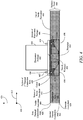
- FIG. 4 a front-view of a radiator panel 400 is shown in accordance with various embodiments.
- an electronics package 402 such as, for example, a TWTA
- a gasket 406 is shown interposed between the bottom 408 of the electronics package 402 and the top 410 of the inside face-sheet 404.
- the radiator panel 400 is shown to have a honeycomb core 412 and heat-pipe 414 embedded in the honeycomb core 412.
- first clipsert 416 and second clipsert 418 are embedded in the honeycomb core 412 .
- the first clipsert 416, first bolt 417, second clipsert 418, and second bolt 419 may be utilized to prevent the gasket 406 from "creeping" (i.e., moving) along the interface-space between the electronics package 402 and inside face-sheet 404.
- the electronics package 402 may be the same as the first electronics package 320 of FIG. 3 .
- the front-view of the radiator panel 400 is looking into the X- axis 410, where the inside face-sheet 404, gasket 406, honeycomb core 412 extend along the X -axis 410 and Y -axis 412 parallel to an X-Y plane.
- the radiator panel 400 forms a sandwiched structure that has layers (i.e., the inside face-sheet 404, honeycomb core 412, a first thermal conductive joint 420, second thermal conductive joint 422, and an outside face-sheet 424) that are oriented in a perpendicular direction (i.e., along a Z-axis 426) to the X-Y plane.
- a portion 428 of the first thermal conductive joint 420 is shown that corresponds to an area located under a portion 430 of the inside face-sheet 404 and the gasket 406.
- the portion 428 of the first thermal conductive joint 420 may have a plurality of CNTs within the adhesive layer that are aligned between the bottom 432 of the inside face-sheet 404 and the top 434 of the heat-pipe 414.
- a portion 436 of the second thermal conductive joint 422 is shown that corresponds to an area located under a portion 438 of the outside face-sheet 424. Both portions 436 and 438 of the second thermal conductive joint 422 and outside face-sheet 424, respectively, also correspond to the area located under the portion 430 of the inside face-sheet 404 and the gasket 406.
- FIG. 5 a cross-sectional view of an enlarged portion 440 of the portion 428 of the first thermal conductive joint 420 along a cutting plane looking into the front of the radiator panel 400 (i.e., the X -axis 410) is shown in FIG. 5 in accordance with the various embodiment.
- a plurality of CNTs 500 are shown extending longitudinally (i.e., along the Z-axis 426) from the inside face-sheet 404 to the heat-pipe 414 through an adhesive layer 502.
- the adhesive layer 502 is part of the first thermal conductive joint 420 corresponding to the portion 428 of the first thermal conductive joint 420 under the gasket 406.
- each CNT of the plurality of CNTs 500 may be oriented in a longitudinal direction (i.e., an axial along the length of the CNTs that correspond to the direction along the Z-axis 426) between the inside face-sheet 404 and the heat-pipe 414.
- This longitudinal direction is approximately perpendicular to the bottom 432 of the inside face-sheet 404 and top 434 of the heat-pipe 414 (i.e., along the Z -axis 426).
- the plurality of CNTs 500 may be continuous between the inside face-sheet 404 and the heat-pipe 414 to a point where the plurality of CNTs 500 may be in physical contact with the inside face-sheet 404 and the heat-pipe 414.
- the plurality of CNTs 500 may act as a thermal bridge from the metal of inside face-sheet 404 to the metal of the heat-pipe 414.
- the plurality of CNTs 500 may act as a substantial thermal bridge through the adhesive layer 502.
- the plurality of CNTs 500 may form a parallel heat conduction path from the inside face-sheet 404 to the heat-pipe 414. It is appreciated by those of ordinary skill in the art that CNTs have extremely high thermal conductivity along the CNT longitudinal axis as compared to an epoxy film adhesive. In general, the thermal conductivity is improved by two to five times with the use of the CNTs.
- the adhesive layer 502 may be an epoxy film disposed between the bottom surface 432 of the inside face-sheet 404 and the top surface 434 of the heat-pipe 414.
- the plurality of CNTs 500 and adhesive 504 in the adhesive layer 502 may be approximately 10 micrometers thick.
- the heat generated by the electronics package 402 is passed from the electronics package 502 through the gasket 406 and inside face-sheet 404 to the adhesive layer 502 having the adhesive 504 and the plurality of CNTs 500.
- the CNTs 500 in the adhesive layer 502 form a thermal bridge between the inside face-sheet 404 and heat-pipe 414 that allows a significantly higher amount of heat to be transferred from the inside face-sheet 404 to the heat-pipe 414 than the adhesive 504 in the adhesive layer 502 is capable of transferring without the presence of the plurality of CNTs 500.
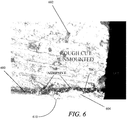
- FIG. 6 a microscopic front-view of an example of an implementation of a bond line 600 between the inside face-sheet 602 and heat-pipe 604 is shown with the plurality of CNTs 606 embedded in the adhesive layer 608 within the bond line 600 in accordance with the various embodiments.
- FIG. 7 a cross-sectional view of an enlarged portion 610 of the adhesive layer 608 is shown in FIG. 7 in accordance with various embodiments.
- the plurality of CNTs 700 are shown approximately parallel and extending approximately perpendicularly between the face-sheet and heat-pipe.
Landscapes
- Engineering & Computer Science (AREA)
- Microelectronics & Electronic Packaging (AREA)
- Physics & Mathematics (AREA)
- Thermal Sciences (AREA)
- Cooling Or The Like Of Semiconductors Or Solid State Devices (AREA)
- Cooling Or The Like Of Electrical Apparatus (AREA)
Abstract
Description
- Various embodiments are related to spacecraft radiator panels and, more particularly, to radiator panels utilizing heat-pipes.
- Spacecraft include a plethora of equipment, such as electronic equipment, that generates heat. This heat must be dissipated, and because space is essentially void of air, the heat must be radiated to outer space. Spacecraft, such as satellites, typically include radiator panels that draw the heat from electronics and other equipment to an outer surface of the spacecraft.
- In
FIG. 1 , a front-view of a schematic diagram of an example of a typical knownradiator panel 100 is shown. Theradiator panel 100 may include an inside face-sheet 102 that faces the inside of the spacecraft, an outside face-sheet 104 that faces the outside of the spacecraft towards outer space, ahoneycomb core 106 positioned between the inside and outside face-sheets 102 and 104 to give theradiator panel 100 structural support, and one or more heat-pipes 108 positioned between the inner and outside face-sheets 102 and 104 to transfer the heat generated by anelectronics package 110 away from theelectronics package 100 to the outside face-sheet 104 and ultimately to outer space. In general, heat-pipes (such as heat-pipe 108) are heat transfer devices that combine the principles of both thermal conductivity and phase transition of a working fluid to transfer heat from one location to another, such as from an electronic device to a heat sink, or in the application of a spacecraft, ultimately to outer space. In an example of operation of the heat-pipe 108, at thehot interface 112 of the heat-pipe 108 a fluid (such as a liquid) in contact with the thermally conductive solid surface of thehot interface 112 turns into a vapor by absorbing heat from that surface of thehot interface 112. The vapor then travels along the heat-pipe 108 to a cold interface (not shown) and condenses back into a liquid - releasing the latent heat in the process. The liquid then returns to thehot interface 112 through capillary action, centrifugal force, or gravity, and the process cycle repeats. In this example, the heat-pipe 108 may include grooved wicks (not shown) along aninner surface 114 and the axial length of the heat-pipe 108. In general, the grooved wicks are utilized in spacecraft, instead of the screen or sintered wicks used for terrestrial heat-pipes, since the heat-pipe 108 does not have to operate against gravity in outer space. This allows the spacecraft heat-pipe 108 to be several meters long, in contrast to the roughly 25 cm of maximum length for a water heat-pipe operating on Earth. In spacecraft applications, typically ammonia is the most common working fluid for spacecraft heat-pipes. Ethane may also be utilized when the heat-pipe 108 operate at temperatures below the ammonia freezing temperature. In this example, theheat flow 120 from theelectronics package 110 to the heat-pipe 108 is shown. - In this example, the
electronics package 110 is shown attached to the top of the inside face-sheet 102 via agasket 116 and twomechanical attachments devices 118 that may be bolts. Alternately, instead of a gasket 116 a layer of room-temperature vulcanizing ("RTV") silicone sealer may be utilized.
Unfortunately in this example, there is usually a thermal choke between the inner surface 122 of the inside face-sheet 102 and thetop surface 124 of the heat-pipe 108 caused by an interface impedance the results from the interface of these different elements. As such, there is an inefficient thermal transfer fromelectronics package 110 to the heat-pipe 108. To better describe the problem, a cross-sectional view of an enlargedview 126 of a portion of theradiator panel 100 along a cutting plane looking into the front of theradiator panel 100, which is perpendicular to heat-pipe 108, is shown. - In
FIG. 2 , a block diagram of an example of an implementation of the enlargedportion 126 of the radiator panel 100 (ofFIG. 1 ) is shown. As before, the enlargedportion 126 includes the portions of the inside face-sheet 102, heat-pipe 108,electronics package 110, and thegasket 116. In this example, a thermal choke on theheat flow 200 between the inside face-sheet 102 and heat-pipe 108 because the thermal transfer characteristics of theimpedance interface 202 between the inside face-sheet 102 and heat-pipe 108 is inefficient. As such, there is a need for new radiator panel structure that more efficiently transfers heat from the face-sheet to the heat-pipe. - Disclosed is a thermal conductive joint between a face-sheet and a heat-pipe on a radiator panel. The thermal conductive joint includes an adhesive layer attached between the face-sheet and the heat-pipe and a plurality of carbon nanotubes ("CNTs") within the adhesive layer.
- The plurality of CNTs may be oriented in an axial direction between the face-sheet and the heat-pipe. This axial direction may be perpendicular to the surface of the face-sheet and surface of the heat-pipe. Additionally, the plurality of CNTs may be continuous between the face-sheet and the heat-pipe to a point where the CNTs may be in physical contact with the face-sheet and heat-pipe. In this example, if the face-sheet and heat-pipe are constructed of metal, the plurality of CNTs may act as a thermal bridge from the metal of face-sheet to the metal of the heat-pipe. In this case, the plurality of CNTs may act as a substantial thermal bridge through the adhesive layer. In this configuration, the plurality of CNTs may form a parallel heat conduction path from the face-sheet to the heat-pipe.
- Other devices, apparatus, systems, methods, features and advantages of the disclosure will be or will become apparent to one with skill in the art upon examination of the following figures and detailed description. It is intended that all such additional systems, methods, features and advantages be included within this description, be within the scope of the disclosure, and be protected by the accompanying claims.
- The disclosure may be better understood by referring to the following figures. The components in the figures are not necessarily to scale, emphasis instead being placed upon illustrating the principles of the disclosure. In the figures, like reference numerals designate corresponding parts throughout the different views.
-
FIG. 1 is a front-view of schematic diagram of an example of a typical radiator panel. -
FIG. 2 is a cross-sectional view of an enlarged portion of the portion of the radiator panel shown inFIG. 1 along a cutting plane looking into the front of the radiator panel in accordance with various embodiments. -
FIG. 3 is an exploded assembly perspective-view of an example of an implementation of a thermal conductive joint between a face-sheet and a heat-pipe embedded in a radiator panel in accordance with various embodiments. -
FIG. 4 is a front view of the radiator panel shown inFIG. 3 in accordance with various embodiments. -
FIG. 5 is a cross-sectional view of an enlarged portion of the portion of the first thermal conductive joint shown inFIG. 4 along a cutting plane looking into the front of the radiator panel in accordance with various embodiments. -
FIG. 6 is a microscopic front-view of an example of an implementation of a bond line between the face-sheet and heat-pipe with a plurality of CNTs embedded in an adhesive layer within the bond line in accordance with various embodiments. -
FIG. 7 is a cross-sectional view of an enlarged portion of the adhesive layer is shown in FIG. 8 in accordance with various embodiments. - Disclosed is a thermal conductive joint between a face-sheet and a heat-pipe on a radiator panel. The thermal conductive joint includes an adhesive layer attached between the face-sheet and the heat-pipe and a plurality of carbon nanotubes ("CNTs") within the adhesive layer.
- The plurality of CNTs may be oriented in an axial direction between the face-sheet and the heat-pipe. This axial direction may be perpendicular to the surface of the face-sheet and surface of the heat-pipe. Additionally, the plurality of CNTs may be continuous between the face-sheet and the heat-pipe to a point where the CNTs may be in physical contact with the face-sheet and heat-pipe. In this example, if the face-sheet and heat-pipe are constructed of metal, the plurality of CNTs may act as a thermal bridge from the metal of face-sheet to the metal of the heat-pipe. In this case, the plurality of CNTs may act as a substantial thermal bridge through the adhesive layer. In this configuration, the plurality of CNTs may form a parallel heat conduction path from the face-sheet to the heat-pipe.
- For the purposes of this disclosure, CNTs are allotropes of carbon with a cylindrical nanostructure. CNTs have been constructed with length-to-diameter ratio of up to 132,000,000:1, significantly larger than for any other material. These cylindrical carbon molecules have unusual properties, which are valuable for nanotechnology, electronics, optics and other fields of materials science and technology. CNTs have very good thermal conductivity and mechanical and electrical properties.
- CNTs are members of the fullerene structural family. Their name is derived from their long, hollow structure with the walls formed by one-atom-thick sheets of carbon, called graphene. These sheets are rolled at specific and discrete ("chiral") angles, and the combination of the rolling angle and radius decides the CNT's properties; for example, whether the individual nanotube shell is a metal or semiconductor. CNTs are generally categorized as single-walled nanotubes ("SWNTs") and multi-walled nanotubes ("MWNTs"). Generally, individual CNTs naturally align themselves into "ropes" held together by van der Waals forces, more specifically, pi-stacking.
- Chemical bonding in CNTs is best described by applied quantum chemistry, specifically, orbital hybridization best describes chemical bonding in nanotubes. The chemical bonding of CNTs is composed entirely of sp2 bonds, similar to those of graphite. These bonds, which are stronger than the sp3 bonds found in alkanes and diamond, provide CNTs with unique strength.
- This unique strength makes CNTs the strongest and stiffest materials yet discovered in terms of tensile strength and elastic modulus respectively. This strength results from the covalent sp2 bonds formed between the individual carbon atoms.
- Turning to
FIG. 3 , an exploded assembly perspective-view of an example of an implementation of a thermal conductive joint 300 between an inside face-sheet 302 and a heat-pipe 304 embedded in aradiator panel 306 is shown in accordance with the present invention. Theradiator panel 306 may also include an outside face-sheet 308 and secondary thermal conductive joint 310 between an outside face-sheet 308 and the heat-pipe 304. Moreover, theradiator panel 306 may also include ahoneycomb core 312 in which the heat-pipe 304 is embedded and which is interposed between the first thermal conductive joint 300 and second thermal conductive joint 310. Thehoneycomb core 312 may also have a first andsecond clipsert honeycomb core 312 adjacent to the heat-pipe 304 and also interposed between the first thermal conductive joint 300 and second thermal conductive joint 310. In this example, theclipserts electronics package 318 so as to allow theelectronics package 318 to be bolted onto the inside face-sheet 302 via bolts (not shown). Similar to the examples shown inFIGs. 1 and2 , theradiator panel 306 may have anelectronics package 318 placed on atop face 320 of the inside face-sheet 302. In this example, theelectronics package 318 may include two traveling wave tube amplifiers ("TWTAs") 322 and 324. - To better understand the elements shown in
FIG. 3 , a reference coordinate system is shown having anX -axis 326, Y-axis 328, and Z-axis 330. In this example, the heat-pipe 304 and TWTAs 322 and 324 extend along theX -axis 326. The inner-face sheet 302, first thermal conductive joint 300,honeycomb core 312, and second thermal conductive joint 310, and outside face-sheet 308 extend outward along theX -axis 326 and Y-axis 328 parallel to anX-Y plane 332. When the exploded assembly of theradiator panel 306 is collapsed, theradiator panel 306 forms a sandwiched structure that has layers that are oriented in a perpendicular direction (i.e., along the Z-axis 326) to theX-Y plane 332. - In this example, the
honeycomb core 312, heat-pipe 304, and clipserts 314 and 316 may be between approximately 0.5 inches to 0.625 inches in thickness. Thehoneycomb core 312 may be made of metal such as, for example, aluminum. The inner and outside face-sheets 302 and 308 may also be made of metal such as, for example aluminum. The first thermal conductive joint 300 is composed of a film adhesive 331 (such as an epoxy film adhesive) and includes aportion 334 of the firstthermal conductivity joint 300 that has a plurality of CNTs oriented and aligned perpendicular to the bond lines (i.e., in the Z-axis 330) locally under aportion 336 of the inside face-sheet 302. Theportion 336 of the inside face-sheet 302 corresponds to an area of the inside face-sheet 302 located under agasket 338 that is located under anunderside 340 of thefirst TWTA 320. Thegasket 338 has atop side 342 that is placed in contact with theunderside 340 of thefirst TWTA 320 and abottom side 344 that corresponds to the area of theportion 336 of the inside face-sheet 302 located under agasket 338. As such, theportion 336 of the inside face-sheet 302 corresponds to the area of thebottom side 344 of thegasket 338. Additionally, the area of theportion 336 of the inside face-sheet 302 also corresponds to an area of theportion 334 of first thermal conductive joint 300. - In this example, the second thermal conductive joint 310 may also include a film adhesive 345 (such as an epoxy film) having a
portion 346 having a plurality of CNTs oriented and aligned perpendicular to the bond lines (i.e., in the Z-direction 330) locally under a portion of the outside face-sheet 308 that corresponds to theportion 334 of the inside face-sheet 302 having the CNTs. In this example, thegasket 338 may be constructed of graphite such as, for example, eGraf® graphite produced by GrafTech International Holdings Inc. of Lakewood, OH. - Turning to
FIG. 4 , a front-view of aradiator panel 400 is shown in accordance with various embodiments. In this example, an electronics package 402 (such as, for example, a TWTA) is shown placed on the inside face-sheet 404 of theradiator panel 400. Agasket 406 is shown interposed between the bottom 408 of theelectronics package 402 and the top 410 of the inside face-sheet 404. Theradiator panel 400 is shown to have ahoneycomb core 412 and heat-pipe 414 embedded in thehoneycomb core 412. Additionally embedded in thehoneycomb core 412 are a first clipsert 416 and second clipsert 418, which allow theelectronics package 402 to be bolted to the first and second clipserts 416 and 418 viabolts first bolt 417, second clipsert 418, andsecond bolt 419 may be utilized to prevent thegasket 406 from "creeping" (i.e., moving) along the interface-space between theelectronics package 402 and inside face-sheet 404.
In this example, theelectronics package 402 may be the same as thefirst electronics package 320 ofFIG. 3 . The front-view of theradiator panel 400 is looking into theX- axis 410, where the inside face-sheet 404,gasket 406,honeycomb core 412 extend along theX -axis 410 and Y-axis 412 parallel to an X-Y plane. Theradiator panel 400 forms a sandwiched structure that has layers (i.e., the inside face-sheet 404,honeycomb core 412, a first thermal conductive joint 420, second thermal conductive joint 422, and an outside face-sheet 424) that are oriented in a perpendicular direction (i.e., along a Z-axis 426) to the X-Y plane. - A
portion 428 of the first thermal conductive joint 420 is shown that corresponds to an area located under aportion 430 of the inside face-sheet 404 and thegasket 406. Theportion 428 of the first thermal conductive joint 420 may have a plurality of CNTs within the adhesive layer that are aligned between the bottom 432 of the inside face-sheet 404 and the top 434 of the heat-pipe 414. Similarly, aportion 436 of the second thermal conductive joint 422 is shown that corresponds to an area located under aportion 438 of the outside face-sheet 424. Bothportions sheet 424, respectively, also correspond to the area located under theportion 430 of the inside face-sheet 404 and thegasket 406. - To better describe the
portion 428 of the first thermal conductive joint 420, a cross-sectional view of anenlarged portion 440 of theportion 428 of the first thermal conductive joint 420 along a cutting plane looking into the front of the radiator panel 400 (i.e., the X-axis 410) is shown inFIG. 5 in accordance with the various embodiment. - From this
enlarged portion view 440, a plurality ofCNTs 500 are shown extending longitudinally (i.e., along the Z-axis 426) from the inside face-sheet 404 to the heat-pipe 414 through anadhesive layer 502. In this view, theadhesive layer 502 is part of the first thermal conductive joint 420 corresponding to theportion 428 of the first thermal conductive joint 420 under thegasket 406. - In this example, each CNT of the plurality of
CNTs 500 may be oriented in a longitudinal direction (i.e., an axial along the length of the CNTs that correspond to the direction along the Z-axis 426) between the inside face-sheet 404 and the heat-pipe 414. This longitudinal direction is approximately perpendicular to thebottom 432 of the inside face-sheet 404 and top 434 of the heat-pipe 414 (i.e., along the Z-axis 426). Additionally, the plurality ofCNTs 500 may be continuous between the inside face-sheet 404 and the heat-pipe 414 to a point where the plurality ofCNTs 500 may be in physical contact with the inside face-sheet 404 and the heat-pipe 414. In this example, if the inside face-sheet 404 and heat-pipe 414 are constructed of metal, the plurality ofCNTs 500 may act as a thermal bridge from the metal of inside face-sheet 404 to the metal of the heat-pipe 414. In this case, the plurality ofCNTs 500 may act as a substantial thermal bridge through theadhesive layer 502. In this configuration, the plurality ofCNTs 500 may form a parallel heat conduction path from the inside face-sheet 404 to the heat-pipe 414. It is appreciated by those of ordinary skill in the art that CNTs have extremely high thermal conductivity along the CNT longitudinal axis as compared to an epoxy film adhesive. In general, the thermal conductivity is improved by two to five times with the use of the CNTs. - In this example, the
adhesive layer 502 may be an epoxy film disposed between thebottom surface 432 of the inside face-sheet 404 and thetop surface 434 of the heat-pipe 414. As an example, the plurality ofCNTs 500 and adhesive 504 in theadhesive layer 502 may be approximately 10 micrometers thick. - In an example of operation, the heat generated by the
electronics package 402 is passed from theelectronics package 502 through thegasket 406 and inside face-sheet 404 to theadhesive layer 502 having the adhesive 504 and the plurality ofCNTs 500. TheCNTs 500 in theadhesive layer 502 form a thermal bridge between the inside face-sheet 404 and heat-pipe 414 that allows a significantly higher amount of heat to be transferred from the inside face-sheet 404 to the heat-pipe 414 than the adhesive 504 in theadhesive layer 502 is capable of transferring without the presence of the plurality ofCNTs 500. - In
FIG. 6 , a microscopic front-view of an example of an implementation of abond line 600 between the inside face-sheet 602 and heat-pipe 604 is shown with the plurality of CNTs 606 embedded in the adhesive layer 608 within thebond line 600 in accordance with the various embodiments. - To better understand how the plurality of
CNTs 600 are aligned parallel to the individual CNTs in the plurality ofCNTs 600 but perpendicularly between the inside face-sheet 602 and heat-pipe 604, a cross-sectional view of anenlarged portion 610 of the adhesive layer 608 is shown inFIG. 7 in accordance with various embodiments. InFIG. 7 , the plurality ofCNTs 700 are shown approximately parallel and extending approximately perpendicularly between the face-sheet and heat-pipe. - Further, the disclosure comprises embodiments according to the following clauses:
- Clause 1. A thermal conductive joint between a face-sheet and a heat-pipe on a radiator panel, the thermal conductive joint comprising:
- an adhesive layer attached between the face-sheet and the heat-pipe; and
- a plurality of carbon nanotubes ("CNTs") within the adhesive layer.
- Clause 2. The thermal conductive joint of Clause 1, wherein the plurality of CNTs are oriented in an axial direction between the face-sheet and the heat-pipe.
- Clause 3. The thermal conductive joint of Clause 2, wherein the plurality of CNTs are continuous between the face-sheet and the heat-pipe.
- Clause 4. The thermal conductive joint of Clause 3, wherein the plurality of CNTs are in physical contact with the face-sheet and heat-pipe creating a thermal bridge from the face-sheet and heat-pipe.
- Clause 5. The thermal conductive joint of Clause 4,
wherein the plurality of CNTs create a substantial thermal bridge through the adhesive layer and
wherein the plurality of CNTs are in physical contact with face-sheet and the heat-pipe. - Clause 6. The thermal conductive joint of Clause 5, wherein the plurality of CNTs form a parallel heat conduction path from the face-sheet to the heat-pipe.
- Clause 7. The thermal conductive joint of Clause 6, wherein the plurality of CNTs are arranged perpendicular to an inner surface of the face-sheet and an inner surface of the heat-pipe.
- Clause 8. The thermal conductive joint of Clause 7, wherein the adhesive layer is an epoxy film disposed between a bottom surface of the face-sheet and a top surface of the heat-pipe.
- Clause 9. The thermal conductive joint of Clause 8, wherein the adhesive layer is approximately 10 micrometers thick.
- Clause 10. The thermal conductive joint of Clause 8, wherein the plurality of CNTs are configured to transfer the maximum amount of heat from a heat source placed on the face-sheet.
- Clause 11. The thermal conductive joint of Clause 10, wherein the heat source is a traveling wave tube amplifier ("TWTA").
- Clause 12. A radiator assembly for a spacecraft, the radiator assembly comprising:
- a face-sheet;
- a heat-pipe; and
- an adhesive epoxy disposed between the face-sheet and the heat-pipe, the adhesive epoxy including a plurality of carbon nanotubes ("CNTs"), wherein the epoxy is configured to bond the face-sheet to the heat-pipe.
- Clause 13. The radiator assembly of Clause 12, wherein the plurality of CNTs are oriented in an axial direction between the face-sheet and the heat-pipe.
- Clause 14. The radiator assembly of Clause 13, wherein the plurality of CNTs are continuous between the face-sheet and the heat-pipe.
- Clause 15. The radiator assembly of Clause 14, wherein the plurality of CNTs are in physical contact with the face-sheet and heat-pipe creating a bridge from the face-sheet and heat-pipe.
- Clause 16. The radiator assembly of Clause 15, wherein the plurality of CNTs create a substantial bridge through the adhesive layer.
- Clause 17. The radiator assembly of Clause 16, wherein the plurality of CNTs form a parallel heat conduction path from the face-sheet to the heat-pipe.
- Clause 18. The radiator assembly of Clause 17, wherein the plurality of CNTs are arranged perpendicular to an inner surface of the face-sheet and an inner surface of the heat-pipe.
- Clause 19. The radiator assembly of Clause 18, wherein the adhesive layer is an epoxy film disposed between the inner surface of the face-sheet and the inner surface of the heat-pipe.
- Clause 20. The radiator assembly of Clause 19, wherein the adhesive layer is approximately 10 micrometers thick.
- It will be understood that various aspects or details of the disclosure may be changed without departing from the scope of the disclosure. It is not exhaustive and does not limit the claimed disclosures to the precise form disclosed. Furthermore, the foregoing description is for the purpose of illustration only, and not for the purpose of limitation. Modifications and variations are possible in light of the above description or may be acquired from practicing the disclosure. The claims and their equivalents define the scope of the disclosure.
Claims (15)
- A thermal conductive joint 420 between a face-sheet 404 and a heat-pipe 414 on a radiator panel 400, the thermal conductive joint comprising:an adhesive layer 502 attached between the face-sheet and the heat-pipe; anda plurality of carbon nanotubes ("CNTs") 500 within the adhesive layer.
- The thermal conductive 420 joint of claim 1, wherein the plurality of CNTs 500 are oriented in an axial direction between the face-sheet 404 and the heat-pipe 414.
- The thermal conductive joint 420 of any of claims 1 to 2, wherein the plurality of CNTs 500 are continuous between the face-sheet 404 and the heat-pipe 414.
- The thermal conductive joint 420 of any of claims 1 to 3, wherein the plurality of CNTs 500 are in physical contact with the face-sheet 404 and heat-pipe 414 creating a thermal bridge from the face-sheet and heat-pipe.
- The thermal conductive joint 420 of any of claims 1 to 4,
wherein the plurality of CNTs 500 create a substantial thermal bridge through the adhesive layer 502 and
wherein the plurality of CNTs 500 are in physical contact with the face-sheet 404 and the heat-pipe 414. - The thermal conductive joint 420 of any of claims 1 to 5, wherein the plurality of CNTs 500 form a parallel heat conduction path from the face-sheet 404 to the heat-pipe 414.
- The thermal conductive joint of any of claims 1 to 6, wherein the plurality of CNTs 500 are arranged perpendicular to an inner surface 432 of the face-sheet 404 and an inner surface of the heat-pipe 414.
- The thermal conductive joint 420 of any of claims 1 to 7, wherein the adhesive layer 502 is an epoxy film disposed between a bottom surface 432 of the face-sheet 404 and a top surface of the heat-pipe 414.
- The thermal conductive joint 420 of any of claims 1 to 8, wherein the plurality of CNTs 500 are configured to transfer the maximum amount of heat from a heat source 402 placed on the face-sheet 404.
- The thermal conductive joint 420 of any of claims 1 to 9, wherein the heat source 402 is a traveling wave tube amplifier ("TWTA").
- A radiator assembly 400 for a spacecraft, the radiator assembly comprising:a face-sheet 404;a heat-pipe 414; andan adhesive epoxy 502 disposed between the face-sheet and the heat-pipe, the adhesive epoxy including a plurality of carbon nanotubes ("CNTs") 500, wherein the epoxy is configured to bond the face-sheet to the heat-pipe.
- The radiator assembly of claim 11, wherein the plurality of CNTs 500 are oriented in an axial direction between the face-sheet 404 and the heat-pipe 414.
- The radiator assembly of any of claims 11-12, wherein the plurality of CNTs 500 are continuous between the face-sheet 404 and the heat-pipe 414.
- The radiator assembly of any of claims 11-13, wherein the plurality of CNTs 500 are in physical contact with the face-sheet 404 and the heat-pipe 414 creating a bridge from the face-sheet and the heat-pipe.
- The radiator assembly of any of claims 11-14, wherein the plurality of CNTs 500 create a substantial bridge through the adhesive layer 502.
Applications Claiming Priority (1)
| Application Number | Priority Date | Filing Date | Title |
|---|---|---|---|
| US14/666,254 US20160286692A1 (en) | 2015-03-23 | 2015-03-23 | High thermal conductivity joint utlizing continuous aligned carbon nanotubes |
Publications (2)
| Publication Number | Publication Date |
|---|---|
| EP3073524A1 true EP3073524A1 (en) | 2016-09-28 |
| EP3073524B1 EP3073524B1 (en) | 2020-11-04 |
Family
ID=55521446
Family Applications (1)
| Application Number | Title | Priority Date | Filing Date |
|---|---|---|---|
| EP16157009.8A Active EP3073524B1 (en) | 2015-03-23 | 2016-02-23 | High thermal conductivity joint utilizing continuous aligned carbon nanotubes |
Country Status (2)
| Country | Link |
|---|---|
| US (1) | US20160286692A1 (en) |
| EP (1) | EP3073524B1 (en) |
Families Citing this family (2)
| Publication number | Priority date | Publication date | Assignee | Title |
|---|---|---|---|---|
| FR3073978B1 (en) * | 2017-11-17 | 2022-10-28 | Inst Vedecom | POWER ELECTRONIC MODULE AND ELECTRONIC SYSTEM COMPRISING SUCH AN ELECTRONIC MODULE |
| CN119841625B (en) * | 2024-05-22 | 2025-12-09 | 钢铁研究总院有限公司 | High-orientation high-compactness ceramic and preparation method and application thereof |
Citations (4)
| Publication number | Priority date | Publication date | Assignee | Title |
|---|---|---|---|---|
| US20060234056A1 (en) * | 2005-04-14 | 2006-10-19 | Tsinghua University | Thermal interface material and method for making the same |
| US20080081176A1 (en) * | 2005-03-24 | 2008-04-03 | Tsinghua University | Thermal interface material and method for manufacturing same |
| US20090129011A1 (en) * | 2007-11-20 | 2009-05-21 | Basic Electronics, Inc. | Liquid cooled module |
| US20110012252A1 (en) * | 2009-07-20 | 2011-01-20 | Gao Shan | Power semiconductor module and method of manufacturing the same |
Family Cites Families (7)
| Publication number | Priority date | Publication date | Assignee | Title |
|---|---|---|---|---|
| US5806803A (en) * | 1995-11-30 | 1998-09-15 | Hughes Electronics Corporation | Spacecraft radiator cooling system |
| US6131646A (en) * | 1998-01-19 | 2000-10-17 | Trw Inc. | Heat conductive interface material |
| US20040009353A1 (en) * | 1999-06-14 | 2004-01-15 | Knowles Timothy R. | PCM/aligned fiber composite thermal interface |
| US6965513B2 (en) * | 2001-12-20 | 2005-11-15 | Intel Corporation | Carbon nanotube thermal interface structures |
| CN100454526C (en) * | 2005-06-30 | 2009-01-21 | 鸿富锦精密工业(深圳)有限公司 | Thermal interface material manufacturing method |
| US8890312B2 (en) * | 2006-05-26 | 2014-11-18 | The Hong Kong University Of Science And Technology | Heat dissipation structure with aligned carbon nanotube arrays and methods for manufacturing and use |
| US9403606B2 (en) * | 2012-03-06 | 2016-08-02 | The Boeing Company | Spacecraft radiator panels |
-
2015
- 2015-03-23 US US14/666,254 patent/US20160286692A1/en not_active Abandoned
-
2016
- 2016-02-23 EP EP16157009.8A patent/EP3073524B1/en active Active
Patent Citations (4)
| Publication number | Priority date | Publication date | Assignee | Title |
|---|---|---|---|---|
| US20080081176A1 (en) * | 2005-03-24 | 2008-04-03 | Tsinghua University | Thermal interface material and method for manufacturing same |
| US20060234056A1 (en) * | 2005-04-14 | 2006-10-19 | Tsinghua University | Thermal interface material and method for making the same |
| US20090129011A1 (en) * | 2007-11-20 | 2009-05-21 | Basic Electronics, Inc. | Liquid cooled module |
| US20110012252A1 (en) * | 2009-07-20 | 2011-01-20 | Gao Shan | Power semiconductor module and method of manufacturing the same |
Also Published As
| Publication number | Publication date |
|---|---|
| US20160286692A1 (en) | 2016-09-29 |
| EP3073524B1 (en) | 2020-11-04 |
Similar Documents
| Publication | Publication Date | Title |
|---|---|---|
| Bar-Cohen et al. | Two-phase thermal ground planes: technology development and parametric results | |
| Kundalwal et al. | Micromechanics modelling of the effective thermoelastic response of nano-tailored composites | |
| Huang et al. | Toward effective synergetic effects from graphene nanoplatelets and carbon nanotubes on thermal conductivity of ultrahigh volume fraction nanocarbon epoxy composites | |
| Sevik et al. | Phonon engineering in carbon nanotubes by controlling defect concentration | |
| Tullius et al. | A review of cooling in microchannels | |
| Ru | Degraded axial buckling strain of multiwalled carbon nanotubes due to interlayer slips | |
| Li et al. | Thermal boundary resistances of carbon nanotubes in contact with metals and polymers | |
| Yu et al. | Effect of an auxiliary plate on passive heat dissipation of carbon nanotube-based materials | |
| Zhang et al. | Thermal rectification at silicon/horizontally aligned carbon nanotube interfaces | |
| Zhang et al. | Influence of temperature change on column buckling of multiwalled carbon nanotubes | |
| NS et al. | Brinkman-Forchheimer flow of SWCNT and MWCNT magneto-nanoliquids in a microchannel with multiple slips and Joule heating aspects | |
| Sihn et al. | Enhancement of through-thickness thermal conductivity in adhesively bonded joints using aligned carbon nanotubes | |
| Zhang et al. | Enhancement of natural convection by carbon nanotube films covered microchannel-surface for passive electronic cooling devices | |
| Xiao et al. | Mechanics of buckled carbon nanotubes on elastomeric substrates | |
| US8776870B2 (en) | Tunable thermal link | |
| Lee et al. | Thermal resistance of CNTs-based thermal interface material for high power solid state device packages | |
| US20110186270A1 (en) | Heat transfer device with anisotropic heat dissipating and absorption structures | |
| US20160282067A1 (en) | High thermal conductivity composite base plate | |
| EP3073524A1 (en) | High thermal conductivity joint utilizing continuous aligned carbon nanotubes | |
| Norris et al. | Prediction and measurement of thermal transport across interfaces between isotropic solids and graphitic materials | |
| Wong et al. | Grooving the carbon nanotube oscillators | |
| Fan et al. | The interfacial thermal conductance between a vertical single-wall carbon nanotube and a silicon substrate | |
| Zhong et al. | A study of CFD simulation for on-chip cooling with 2D CNT micro-fin array | |
| Gharib-Zahedi et al. | Transversal thermal transport in single-walled carbon nanotube bundles: Influence of axial stretching and intertube bonding | |
| Ismail et al. | Cfd analysis for optimum thermal design of carbon nanotube based micro-channel heatsink |
Legal Events
| Date | Code | Title | Description |
|---|---|---|---|
| PUAI | Public reference made under article 153(3) epc to a published international application that has entered the european phase |
Free format text: ORIGINAL CODE: 0009012 |
|
| AK | Designated contracting states |
Kind code of ref document: A1 Designated state(s): AL AT BE BG CH CY CZ DE DK EE ES FI FR GB GR HR HU IE IS IT LI LT LU LV MC MK MT NL NO PL PT RO RS SE SI SK SM TR |
|
| AX | Request for extension of the european patent |
Extension state: BA ME |
|
| STAA | Information on the status of an ep patent application or granted ep patent |
Free format text: STATUS: REQUEST FOR EXAMINATION WAS MADE |
|
| 17P | Request for examination filed |
Effective date: 20170328 |
|
| RBV | Designated contracting states (corrected) |
Designated state(s): AL AT BE BG CH CY CZ DE DK EE ES FI FR GB GR HR HU IE IS IT LI LT LU LV MC MK MT NL NO PL PT RO RS SE SI SK SM TR |
|
| STAA | Information on the status of an ep patent application or granted ep patent |
Free format text: STATUS: EXAMINATION IS IN PROGRESS |
|
| 17Q | First examination report despatched |
Effective date: 20180323 |
|
| GRAP | Despatch of communication of intention to grant a patent |
Free format text: ORIGINAL CODE: EPIDOSNIGR1 |
|
| STAA | Information on the status of an ep patent application or granted ep patent |
Free format text: STATUS: GRANT OF PATENT IS INTENDED |
|
| RIC1 | Information provided on ipc code assigned before grant |
Ipc: H01L 23/42 20060101ALI20200504BHEP Ipc: H01L 25/07 20060101ALI20200504BHEP Ipc: H01L 23/473 20060101ALN20200504BHEP Ipc: H05K 7/20 20060101ALI20200504BHEP Ipc: H01L 23/427 20060101ALI20200504BHEP Ipc: H01L 23/373 20060101AFI20200504BHEP |
|
| RIC1 | Information provided on ipc code assigned before grant |
Ipc: H01L 23/373 20060101AFI20200511BHEP Ipc: H01L 23/42 20060101ALI20200511BHEP Ipc: H01L 23/427 20060101ALI20200511BHEP Ipc: H05K 7/20 20060101ALI20200511BHEP Ipc: H01L 25/07 20060101ALI20200511BHEP Ipc: H01L 23/473 20060101ALN20200511BHEP |
|
| INTG | Intention to grant announced |
Effective date: 20200528 |
|
| GRAS | Grant fee paid |
Free format text: ORIGINAL CODE: EPIDOSNIGR3 |
|
| GRAA | (expected) grant |
Free format text: ORIGINAL CODE: 0009210 |
|
| STAA | Information on the status of an ep patent application or granted ep patent |
Free format text: STATUS: THE PATENT HAS BEEN GRANTED |
|
| AK | Designated contracting states |
Kind code of ref document: B1 Designated state(s): AL AT BE BG CH CY CZ DE DK EE ES FI FR GB GR HR HU IE IS IT LI LT LU LV MC MK MT NL NO PL PT RO RS SE SI SK SM TR |
|
| REG | Reference to a national code |
Ref country code: GB Ref legal event code: FG4D |
|
| REG | Reference to a national code |
Ref country code: CH Ref legal event code: EP |
|
| REG | Reference to a national code |
Ref country code: AT Ref legal event code: REF Ref document number: 1331918 Country of ref document: AT Kind code of ref document: T Effective date: 20201115 |
|
| REG | Reference to a national code |
Ref country code: IE Ref legal event code: FG4D |
|
| REG | Reference to a national code |
Ref country code: DE Ref legal event code: R096 Ref document number: 602016046980 Country of ref document: DE |
|
| REG | Reference to a national code |
Ref country code: NL Ref legal event code: MP Effective date: 20201104 |
|
| REG | Reference to a national code |
Ref country code: AT Ref legal event code: MK05 Ref document number: 1331918 Country of ref document: AT Kind code of ref document: T Effective date: 20201104 |
|
| PG25 | Lapsed in a contracting state [announced via postgrant information from national office to epo] |
Ref country code: PT Free format text: LAPSE BECAUSE OF FAILURE TO SUBMIT A TRANSLATION OF THE DESCRIPTION OR TO PAY THE FEE WITHIN THE PRESCRIBED TIME-LIMIT Effective date: 20210304 Ref country code: RS Free format text: LAPSE BECAUSE OF FAILURE TO SUBMIT A TRANSLATION OF THE DESCRIPTION OR TO PAY THE FEE WITHIN THE PRESCRIBED TIME-LIMIT Effective date: 20201104 Ref country code: FI Free format text: LAPSE BECAUSE OF FAILURE TO SUBMIT A TRANSLATION OF THE DESCRIPTION OR TO PAY THE FEE WITHIN THE PRESCRIBED TIME-LIMIT Effective date: 20201104 Ref country code: NO Free format text: LAPSE BECAUSE OF FAILURE TO SUBMIT A TRANSLATION OF THE DESCRIPTION OR TO PAY THE FEE WITHIN THE PRESCRIBED TIME-LIMIT Effective date: 20210204 Ref country code: GR Free format text: LAPSE BECAUSE OF FAILURE TO SUBMIT A TRANSLATION OF THE DESCRIPTION OR TO PAY THE FEE WITHIN THE PRESCRIBED TIME-LIMIT Effective date: 20210205 |
|
| PG25 | Lapsed in a contracting state [announced via postgrant information from national office to epo] |
Ref country code: AT Free format text: LAPSE BECAUSE OF FAILURE TO SUBMIT A TRANSLATION OF THE DESCRIPTION OR TO PAY THE FEE WITHIN THE PRESCRIBED TIME-LIMIT Effective date: 20201104 Ref country code: ES Free format text: LAPSE BECAUSE OF FAILURE TO SUBMIT A TRANSLATION OF THE DESCRIPTION OR TO PAY THE FEE WITHIN THE PRESCRIBED TIME-LIMIT Effective date: 20201104 Ref country code: BG Free format text: LAPSE BECAUSE OF FAILURE TO SUBMIT A TRANSLATION OF THE DESCRIPTION OR TO PAY THE FEE WITHIN THE PRESCRIBED TIME-LIMIT Effective date: 20210204 Ref country code: PL Free format text: LAPSE BECAUSE OF FAILURE TO SUBMIT A TRANSLATION OF THE DESCRIPTION OR TO PAY THE FEE WITHIN THE PRESCRIBED TIME-LIMIT Effective date: 20201104 Ref country code: LV Free format text: LAPSE BECAUSE OF FAILURE TO SUBMIT A TRANSLATION OF THE DESCRIPTION OR TO PAY THE FEE WITHIN THE PRESCRIBED TIME-LIMIT Effective date: 20201104 Ref country code: SE Free format text: LAPSE BECAUSE OF FAILURE TO SUBMIT A TRANSLATION OF THE DESCRIPTION OR TO PAY THE FEE WITHIN THE PRESCRIBED TIME-LIMIT Effective date: 20201104 Ref country code: IS Free format text: LAPSE BECAUSE OF FAILURE TO SUBMIT A TRANSLATION OF THE DESCRIPTION OR TO PAY THE FEE WITHIN THE PRESCRIBED TIME-LIMIT Effective date: 20210304 |
|
| REG | Reference to a national code |
Ref country code: LT Ref legal event code: MG9D |
|
| PG25 | Lapsed in a contracting state [announced via postgrant information from national office to epo] |
Ref country code: HR Free format text: LAPSE BECAUSE OF FAILURE TO SUBMIT A TRANSLATION OF THE DESCRIPTION OR TO PAY THE FEE WITHIN THE PRESCRIBED TIME-LIMIT Effective date: 20201104 |
|
| PG25 | Lapsed in a contracting state [announced via postgrant information from national office to epo] |
Ref country code: SK Free format text: LAPSE BECAUSE OF FAILURE TO SUBMIT A TRANSLATION OF THE DESCRIPTION OR TO PAY THE FEE WITHIN THE PRESCRIBED TIME-LIMIT Effective date: 20201104 Ref country code: RO Free format text: LAPSE BECAUSE OF FAILURE TO SUBMIT A TRANSLATION OF THE DESCRIPTION OR TO PAY THE FEE WITHIN THE PRESCRIBED TIME-LIMIT Effective date: 20201104 Ref country code: EE Free format text: LAPSE BECAUSE OF FAILURE TO SUBMIT A TRANSLATION OF THE DESCRIPTION OR TO PAY THE FEE WITHIN THE PRESCRIBED TIME-LIMIT Effective date: 20201104 Ref country code: CZ Free format text: LAPSE BECAUSE OF FAILURE TO SUBMIT A TRANSLATION OF THE DESCRIPTION OR TO PAY THE FEE WITHIN THE PRESCRIBED TIME-LIMIT Effective date: 20201104 Ref country code: SM Free format text: LAPSE BECAUSE OF FAILURE TO SUBMIT A TRANSLATION OF THE DESCRIPTION OR TO PAY THE FEE WITHIN THE PRESCRIBED TIME-LIMIT Effective date: 20201104 Ref country code: LT Free format text: LAPSE BECAUSE OF FAILURE TO SUBMIT A TRANSLATION OF THE DESCRIPTION OR TO PAY THE FEE WITHIN THE PRESCRIBED TIME-LIMIT Effective date: 20201104 |
|
| REG | Reference to a national code |
Ref country code: DE Ref legal event code: R097 Ref document number: 602016046980 Country of ref document: DE |
|
| PG25 | Lapsed in a contracting state [announced via postgrant information from national office to epo] |
Ref country code: DK Free format text: LAPSE BECAUSE OF FAILURE TO SUBMIT A TRANSLATION OF THE DESCRIPTION OR TO PAY THE FEE WITHIN THE PRESCRIBED TIME-LIMIT Effective date: 20201104 |
|
| PLBE | No opposition filed within time limit |
Free format text: ORIGINAL CODE: 0009261 |
|
| STAA | Information on the status of an ep patent application or granted ep patent |
Free format text: STATUS: NO OPPOSITION FILED WITHIN TIME LIMIT |
|
| PG25 | Lapsed in a contracting state [announced via postgrant information from national office to epo] |
Ref country code: MC Free format text: LAPSE BECAUSE OF FAILURE TO SUBMIT A TRANSLATION OF THE DESCRIPTION OR TO PAY THE FEE WITHIN THE PRESCRIBED TIME-LIMIT Effective date: 20201104 |
|
| 26N | No opposition filed |
Effective date: 20210805 |
|
| REG | Reference to a national code |
Ref country code: BE Ref legal event code: MM Effective date: 20210228 |
|
| PG25 | Lapsed in a contracting state [announced via postgrant information from national office to epo] |
Ref country code: IT Free format text: LAPSE BECAUSE OF FAILURE TO SUBMIT A TRANSLATION OF THE DESCRIPTION OR TO PAY THE FEE WITHIN THE PRESCRIBED TIME-LIMIT Effective date: 20201104 Ref country code: AL Free format text: LAPSE BECAUSE OF FAILURE TO SUBMIT A TRANSLATION OF THE DESCRIPTION OR TO PAY THE FEE WITHIN THE PRESCRIBED TIME-LIMIT Effective date: 20201104 Ref country code: CH Free format text: LAPSE BECAUSE OF NON-PAYMENT OF DUE FEES Effective date: 20210228 Ref country code: NL Free format text: LAPSE BECAUSE OF FAILURE TO SUBMIT A TRANSLATION OF THE DESCRIPTION OR TO PAY THE FEE WITHIN THE PRESCRIBED TIME-LIMIT Effective date: 20201104 Ref country code: LU Free format text: LAPSE BECAUSE OF NON-PAYMENT OF DUE FEES Effective date: 20210223 Ref country code: LI Free format text: LAPSE BECAUSE OF NON-PAYMENT OF DUE FEES Effective date: 20210228 |
|
| PG25 | Lapsed in a contracting state [announced via postgrant information from national office to epo] |
Ref country code: SI Free format text: LAPSE BECAUSE OF FAILURE TO SUBMIT A TRANSLATION OF THE DESCRIPTION OR TO PAY THE FEE WITHIN THE PRESCRIBED TIME-LIMIT Effective date: 20201104 |
|
| PG25 | Lapsed in a contracting state [announced via postgrant information from national office to epo] |
Ref country code: IE Free format text: LAPSE BECAUSE OF NON-PAYMENT OF DUE FEES Effective date: 20210223 |
|
| PG25 | Lapsed in a contracting state [announced via postgrant information from national office to epo] |
Ref country code: IS Free format text: LAPSE BECAUSE OF FAILURE TO SUBMIT A TRANSLATION OF THE DESCRIPTION OR TO PAY THE FEE WITHIN THE PRESCRIBED TIME-LIMIT Effective date: 20210304 |
|
| PG25 | Lapsed in a contracting state [announced via postgrant information from national office to epo] |
Ref country code: BE Free format text: LAPSE BECAUSE OF NON-PAYMENT OF DUE FEES Effective date: 20210228 |
|
| PG25 | Lapsed in a contracting state [announced via postgrant information from national office to epo] |
Ref country code: HU Free format text: LAPSE BECAUSE OF FAILURE TO SUBMIT A TRANSLATION OF THE DESCRIPTION OR TO PAY THE FEE WITHIN THE PRESCRIBED TIME-LIMIT; INVALID AB INITIO Effective date: 20160223 |
|
| P01 | Opt-out of the competence of the unified patent court (upc) registered |
Effective date: 20230516 |
|
| PG25 | Lapsed in a contracting state [announced via postgrant information from national office to epo] |
Ref country code: CY Free format text: LAPSE BECAUSE OF FAILURE TO SUBMIT A TRANSLATION OF THE DESCRIPTION OR TO PAY THE FEE WITHIN THE PRESCRIBED TIME-LIMIT Effective date: 20201104 |
|
| PG25 | Lapsed in a contracting state [announced via postgrant information from national office to epo] |
Ref country code: MK Free format text: LAPSE BECAUSE OF FAILURE TO SUBMIT A TRANSLATION OF THE DESCRIPTION OR TO PAY THE FEE WITHIN THE PRESCRIBED TIME-LIMIT Effective date: 20201104 |
|
| PG25 | Lapsed in a contracting state [announced via postgrant information from national office to epo] |
Ref country code: TR Free format text: LAPSE BECAUSE OF FAILURE TO SUBMIT A TRANSLATION OF THE DESCRIPTION OR TO PAY THE FEE WITHIN THE PRESCRIBED TIME-LIMIT Effective date: 20201104 |
|
| PG25 | Lapsed in a contracting state [announced via postgrant information from national office to epo] |
Ref country code: MT Free format text: LAPSE BECAUSE OF FAILURE TO SUBMIT A TRANSLATION OF THE DESCRIPTION OR TO PAY THE FEE WITHIN THE PRESCRIBED TIME-LIMIT Effective date: 20201104 |
|
| REG | Reference to a national code |
Ref country code: DE Ref legal event code: R079 Ref document number: 602016046980 Country of ref document: DE Free format text: PREVIOUS MAIN CLASS: H01L0023373000 Ipc: H10W0040250000 |
|
| PGFP | Annual fee paid to national office [announced via postgrant information from national office to epo] |
Ref country code: GB Payment date: 20260227 Year of fee payment: 11 |
|
| PGFP | Annual fee paid to national office [announced via postgrant information from national office to epo] |
Ref country code: DE Payment date: 20260227 Year of fee payment: 11 |
|
| PGFP | Annual fee paid to national office [announced via postgrant information from national office to epo] |
Ref country code: FR Payment date: 20260225 Year of fee payment: 11 |