EP3073507A1 - Apparatus for auxiliary contact of circuit breaker - Google Patents
Apparatus for auxiliary contact of circuit breaker Download PDFInfo
- Publication number
- EP3073507A1 EP3073507A1 EP15203040.9A EP15203040A EP3073507A1 EP 3073507 A1 EP3073507 A1 EP 3073507A1 EP 15203040 A EP15203040 A EP 15203040A EP 3073507 A1 EP3073507 A1 EP 3073507A1
- Authority
- EP
- European Patent Office
- Prior art keywords
- contactor
- movable contactor
- fixed
- circuit breaker
- movable
- Prior art date
- Legal status (The legal status is an assumption and is not a legal conclusion. Google has not performed a legal analysis and makes no representation as to the accuracy of the status listed.)
- Granted
Links
Images


Classifications
-
- H—ELECTRICITY
- H01—ELECTRIC ELEMENTS
- H01H—ELECTRIC SWITCHES; RELAYS; SELECTORS; EMERGENCY PROTECTIVE DEVICES
- H01H71/00—Details of the protective switches or relays covered by groups H01H73/00 - H01H83/00
- H01H71/10—Operating or release mechanisms
- H01H71/12—Automatic release mechanisms with or without manual release
- H01H71/46—Automatic release mechanisms with or without manual release having means for operating auxiliary contacts additional to the main contacts
-
- H—ELECTRICITY
- H01—ELECTRIC ELEMENTS
- H01H—ELECTRIC SWITCHES; RELAYS; SELECTORS; EMERGENCY PROTECTIVE DEVICES
- H01H71/00—Details of the protective switches or relays covered by groups H01H73/00 - H01H83/00
- H01H71/10—Operating or release mechanisms
-
- H—ELECTRICITY
- H01—ELECTRIC ELEMENTS
- H01H—ELECTRIC SWITCHES; RELAYS; SELECTORS; EMERGENCY PROTECTIVE DEVICES
- H01H1/00—Contacts
- H01H1/12—Contacts characterised by the manner in which co-operating contacts engage
- H01H1/14—Contacts characterised by the manner in which co-operating contacts engage by abutting
- H01H1/24—Contacts characterised by the manner in which co-operating contacts engage by abutting with resilient mounting
- H01H1/26—Contacts characterised by the manner in which co-operating contacts engage by abutting with resilient mounting with spring blade support
-
- H—ELECTRICITY
- H01—ELECTRIC ELEMENTS
- H01H—ELECTRIC SWITCHES; RELAYS; SELECTORS; EMERGENCY PROTECTIVE DEVICES
- H01H13/00—Switches having rectilinearly-movable operating part or parts adapted for pushing or pulling in one direction only, e.g. push-button switch
- H01H13/50—Switches having rectilinearly-movable operating part or parts adapted for pushing or pulling in one direction only, e.g. push-button switch having a single operating member
- H01H13/52—Switches having rectilinearly-movable operating part or parts adapted for pushing or pulling in one direction only, e.g. push-button switch having a single operating member the contact returning to its original state immediately upon removal of operating force, e.g. bell-push switch
-
- H—ELECTRICITY
- H01—ELECTRIC ELEMENTS
- H01H—ELECTRIC SWITCHES; RELAYS; SELECTORS; EMERGENCY PROTECTIVE DEVICES
- H01H71/00—Details of the protective switches or relays covered by groups H01H73/00 - H01H83/00
- H01H71/10—Operating or release mechanisms
- H01H71/12—Automatic release mechanisms with or without manual release
- H01H71/46—Automatic release mechanisms with or without manual release having means for operating auxiliary contacts additional to the main contacts
- H01H71/465—Self-contained, easily replaceable microswitches
-
- H—ELECTRICITY
- H01—ELECTRIC ELEMENTS
- H01H—ELECTRIC SWITCHES; RELAYS; SELECTORS; EMERGENCY PROTECTIVE DEVICES
- H01H2205/00—Movable contacts
- H01H2205/002—Movable contacts fixed to operating part
Definitions
- the present disclosure relates to an apparatus for auxiliary contact of a circuit breaker, and more particularly, to an apparatus for auxiliary contact of a circuit breaker, which can improve the reliability in displaying, to the outside, a normal or overcurrent state of the circuit breaker through the apparatus, reduce the manufacturing cost of the apparatus and simplify the entire structure of the apparatus by reducing the number of components used in the apparatus, and prevent components from being easily broken in the use of the apparatus.
- a circuit breaker refers to a device for opening/closing a load or interrupting current when there occurs an accident such as earthing or short circuit in a transmission & sub-station system or an electrical circuit.
- a circuit breaker in which a circuit breaking part is insulated by an insulator and assembled, may generally manually open or close a line in use or may open or close the line from a remote area through an electrical manipulator, or the like, outside a metal container. Also, when there occurs an overload or short-circuit, the circuit breaker automatically cuts off the line to protect an electric power system and a load device.
- a fixed contactor and a movable contactor are installed in a circuit breaking part.
- the fixed contactor and the movable contactor are contacted with each other to allow current to flow therethrough.
- the movable contactor is rapidly separated from the fixed contactor, thereby interrupting current.
- a circuit breaker may be classified into an air operation method, a hydraulic operating method, a spring operation method, and the like according to the way in which a circuit breaking part is operated.
- a circuit breaker may also be classified into an air circuit breaker (ACB) that extinguishes arc by blowing air, a gas circuit breaker (GCB) that extinguishes arc by blowing gas, and the like, according to the way in which arc generated when a movable contactor is separated from a fixed contactor by manipulating a circuit breaking part is extinguished.
- a circuit breaker may also be classified into an air circuit breaker (ACB) that extinguishes arc by blowing air, a gas circuit breaker (GCB) that extinguishes arc by blowing gas, and the like, according to the way in which arc generated when a movable contactor is separated from a fixed contactor by manipulating a circuit breaking part is extinguished.
- ACB air circuit breaker
- a separate apparatus for auxiliary contact is generally installed in a circuit breaking part.
- the apparatus refers to an apparatus that transmits signals to the outside according to opening/closing of a circuit breaking part, i.e., connection and interruption between a fixed contactor and a movable contactor.
- FIG. 1 is a configuration view showing a conventional apparatus for auxiliary contact of a circuit breaker.
- FIG. 2 is a configuration view showing a state in which a state of the apparatus when the circuit breaker is in a normal state.
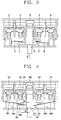
- FIG. 3 is a configuration view showing a state in which the apparatus is pressurized as an overcurrent is applied to the circuit breaker.
- the apparatus is configured to include a fixed contactor 12, a screw portion 11 fixing the fixed contactor 12, a movable contactor 13 contacted with or separated from the fixed contactor 12, a crossbar 14 moving upward the movable contactor 13, the crossbar 14 having a spring 16 provided therein, a lever 15 formed under the crossbar 14.
- the movable contactor 13 is contacted with or separated from the fixed contactor 12 as the lever 15 and the crossbar 14 move upward, thereby displaying a state of the circuit breaker to the outside.
- the movable contactor 13 is provided inside the frame 10 in a state in which the movable contactor 13 is bent to a predetermined angle.
- a restoring force corresponding to bending of the movable contactor 13 through the crossbar 14 in addition to self-bending of the movable contactor 13, has influence on the movable contactor 13.
- the crossbar 14 and the lever 15 which move upward the movable contactor 13 are not formed as one component but separately formed, and hence the number of components is increased. Therefore, the manufacturing cost of the apparatus is increased, and the structure of the apparatus is complicated.
- a separate crossbar 14 should be manufactured and used according to the structure of the movable contactor 13 and the fixed contactor 12.
- an aspect of the detailed description is to provide an apparatus for auxiliary contact of a circuit breaker, which can improve the reliability in displaying, to the outside, a normal or overcurrent state of the circuit breaker through the apparatus, reduce the manufacturing cost of the apparatus and simplify the entire structure of the apparatus by reducing the number of components used in the apparatus, and prevent components from being easily broken in the use of the apparatus.
- an apparatus for auxiliary contact of a circuit breaker includes: a frame; a fixed contactor fixed to the frame inside the frame; a movable contactor installed inside the frame to be contacted with or separated from the fixed contactor; and a contact control member installed inside the frame, the contact control member being formed in a straight line shape, the contact control member being pressurized upward as an overcurrent is applied to the circuit breaker to allow the movable contactor to be contacted with or separated from the fixed contactor.
- the movable contactor may be located to be inclined inside the frame.
- the fixed contactor may include a first fixed contactor and a second fixed contactor
- the movable contactor may include a first movable contactor located over the first fixed contactor and a second movable contactor located under the second fixed contactor, so that when the circuit breaker is in a normal state, the first movable contactor is contacted with the first fixed contactor and the second movable contactor is separated from the second fixed contactor, and when an overcurrent is applied to the circuit breaker, the first movable contactor is separated from the first fixed contactor and the second movable contactor is contacted with the second fixed contactor.
- the contact control member may include a body portion located inside the circuit breaker to move up/down, and a moving plate provided at both sides of the body portion to allow the movable contactor to be contacted with or separated from the fixed contactor by moving the movable contactor as the body portion moves.
- the length of one side of the moving plate in a direction perpendicular to the moving direction of the body portion may be shorter than the length between the outer side surface of the body portion and the fixed contactor.
- the moving plate may be located to be adhered closely to an inner surface of the frame before the body portion is pressurized upward.
- the movable contactor is formed in the straight line shape and located to be inclined inside the auxiliary contact, so that when the movable contactor is contacted with or separated from the fixed contactor through the contact control member, the movable contactor is influenced by only self-bending thereof without any influence of other components, thereby minimizing factors having influence on operational characteristics in contact or separation between the movable contactor and the fixed contactor.
- the movable contactor is formed in the straight line shape and located to be inclined inside the auxiliary contact, so that when the movable contactor is contacted with or separated from the fixed contactor through the contact control member, the movable contactor is influenced by only self-bending thereof without any influence of other components, thereby minimizing factors having influence on operational characteristics in contact or separation between the movable contactor and the fixed contactor.
- the movable contactor is formed in the straight line shape, the movable contactor can be easily manufactured as compared with when the movable contactor is used in its bent state. Thus, it is possible to prevent inferior products from being mass-produced in manufacturing of the movable contactor and simplify the manufacturing process of the movable contactor.
- the contact control member moving the movable contactor is integrally formed as one component, so that the number of components is decreased. Thus, it is possible to reduce the manufacturing cost of the apparatus and simplify the structure of the apparatus.
- the contact control member is formed as one component, and the moving plate is also formed at a lower portion of the contact control member.
- one contact control member can be used in various structures without separately manufacturing contact control members according to structures of the movable contactor and the fixed contactor.
- FIG. 4 is a configuration view showing a state of an apparatus for auxiliary contact of a circuit breaker when the circuit breaker is in a normal state according to an exemplary embodiment.
- FIG. 5 is a configuration view showing a state in which the apparatus is pressurized as an overcurrent is applied to the circuit beaker according to the exemplary embodiment.
- components are provided inside a frame 100.
- a fixed contactor 120 a movable contactor 130, a screw portion 110, a contact control member 140, and the like are provided inside the frame 100.
- the fixed contactor 120 is integrally formed with a fixing plate 150 inside the frame 100 to be fixed to the fixing plate 150 through the screw portion 110 passing through the fixing plate 150.
- the fixed contactor 120 is contacted with or separated from the movable contactor 130, thereby displaying a state of the circuit breaker to the outside.
- the fixed contactor 120 includes a first fixed contactor 120a and a second fixed contactor 120b.
- the first fixed contactor 120a and the second fixed contactor 120b are located both sides of the contact control member 140.
- the movable contactor 130 is formed in a straight line shape, and located to be inclined in a state in which one side of the movable contactor 130 is fixed to an inner surface of the frame 100. Thus, the movable contactor 130 is contacted with or separated from the fixed contactor 120 as the contact control member 140 moves up/down, thereby displaying a state of the circuit breaker to the outside.
- the movable contactor 130 includes a first movable contactor 130a and a second movable contactor 130b.
- the first movable contactor 130a is located over the first fixed contactor 120a
- the second movable contactor 130b is located under the second fixed contactor 120b.
- the first movable contactor 130a is contacted with or separated from the first fixed contactor 120a through the contact control member 140
- the second movable contactor 130b is contacted with or separated from the second fixed contactor 120 through the contact control member 140.
- the movable contactor 130 is contacted with or separated from the fixed contactor 120 as the contact control member 140 moves up/down in a state in which the movable stator 130 is provided in the apparatus to be bent to a predetermined angle.
- the movable contactor 130 is contacted with or separated from the fixed contactor 120 as the contact control member moves in a state in which the movable contactor 130 is bent to an extent.
- the movable contactor 130 is easily deformed, and therefore, operational characteristics of the movable contactor 130 and the fixed contactor 120 are easily changed.
- the movable contactor 130 is formed in a straight line shape so as not to be bent, so that it is possible to prevent an error from occurring in manufacturing of the apparatus.
- the movable contactor 130 is not only formed to have the straight line shape but also located to be inclined.
- the movable contactor 130 is influenced by only self-bending thereof, so that it is possible to prevent operational characteristics of the apparatus from being easily changed when the movable contactor 130 and the fixed contactor 120 are contacted with or separated from each other.
- the contact control member 140 is provided inside the frame 100. Thus, if an overcurrent is applied to the circuit breaker, the contact control member 140 is pressurized to push the movable contactor 130 while moving upward, so that the movable contactor 130 is contacted with or separated from the fixed contactor 120.
- the contact control member 140 includes a body portion 141 and a moving plate 143.
- the body portion 141 is provided inside the frame 100 to move up/down inside the frame 100, and the moving plate 143 is integrally formed with the body portion 141 at both sides of the body portion 141, to allow the movable contactor 130 to be contacted with or separated from the fixed contactor 120 while moving up/down as the body portion 141 moves.
- a front lower surface of the second movable contactor 130b is contacted with one upper end of the moving plate 143, and a front end of the first movable contactor 130a is located at the other side of the moving plate 143 to be upwardly spaced apart from the moving plate 143.
- the first movable contactor 130a is contacted with the first fixed contactor 120a, and the second movable contactor 130b is separated from the second fixed contactor 120b.
- the contact control member 140 is pressurized to move upward as an overcurrent is applied to the circuit breaker, the first movable contactor 130a and the second movable contactor 130b are moved upward by the moving plate 143.
- the first movable contactor 130a is separated from the first fixed contactor 120a, and the second movable contactor 130b is contacted with the second fixed contactor 120b, thereby displaying, to the outside, whether the overcurrent has been applied to the circuit breaker.
- the moving plate 143 is located to be adhered closely to a bottom surface of the frame 100 before the contact control member 140 is pressurized upward.
- the length L2 of one side of the moving plate 143 in a direction perpendicular to the moving direction of the body portion 141 is formed shorter than the length L1 between the outer side surface of the body portion 141 and the fixed contactor 120.
- the apparatus is configured such that the movable contactor is moved in the state in which the lever is inserted into the crossbar at a lower portion of the crossbar, and therefore, a plurality of components are used to move the movable contactor.
- the contact control member is not formed with a plurality of components but integrally formed as one component. Thus, it is possible to decrease the number of components used in the apparatus and simplify the structure of the apparatus.
- the moving plate 143 is located to be adhered closely to the bottom surface of the frame 100 before the moving plate 143 is pressurized, and the length L2 of one side of the moving plate 143 in a direction perpendicular to the moving direction of the body portion 141 is formed shorter than the length L1 between the outer side surface of the body portion 141 and the fixed contactor 120.
- the one contact control member 140 can be used in various structures without using contact control members separately formed according to structures of the movable contactor 130 and the fixed contactor 120, thereby reducing the manufacturing cost of the apparatus.
- the moving plate 143 when the circuit breaker is in a normal state, the moving plate 143 is adhered closely to the bottom surface of the frame 100 in the state in which the contact control member 140 is not pressurized. If an overcurrent is applied to the circuit breaker, the contact control member 140 is pressurized upward, so that the movable contactors 130a and 130b located at both the sides of contact control member 140 are moved through the moving plate 143 to be contacted with or separated from the fixed contactors 120a and 120b.
Landscapes
- Breakers (AREA)
- Thermally Actuated Switches (AREA)
- Physics & Mathematics (AREA)
- Electromagnetism (AREA)
Abstract
Description
- The present disclosure relates to an apparatus for auxiliary contact of a circuit breaker, and more particularly, to an apparatus for auxiliary contact of a circuit breaker, which can improve the reliability in displaying, to the outside, a normal or overcurrent state of the circuit breaker through the apparatus, reduce the manufacturing cost of the apparatus and simplify the entire structure of the apparatus by reducing the number of components used in the apparatus, and prevent components from being easily broken in the use of the apparatus.
- In general, a circuit breaker refers to a device for opening/closing a load or interrupting current when there occurs an accident such as earthing or short circuit in a transmission & sub-station system or an electrical circuit. Also, a circuit breaker, in which a circuit breaking part is insulated by an insulator and assembled, may generally manually open or close a line in use or may open or close the line from a remote area through an electrical manipulator, or the like, outside a metal container. Also, when there occurs an overload or short-circuit, the circuit breaker automatically cuts off the line to protect an electric power system and a load device.
- In a circuit breaker as described above, a fixed contactor and a movable contactor are installed in a circuit breaking part. The fixed contactor and the movable contactor are contacted with each other to allow current to flow therethrough. In addition, when a large current flows due to a defect of the circuit breaker, the movable contactor is rapidly separated from the fixed contactor, thereby interrupting current.
- Meanwhile, a circuit breaker may be classified into an air operation method, a hydraulic operating method, a spring operation method, and the like according to the way in which a circuit breaking part is operated. A circuit breaker may also be classified into an air circuit breaker (ACB) that extinguishes arc by blowing air, a gas circuit breaker (GCB) that extinguishes arc by blowing gas, and the like, according to the way in which arc generated when a movable contactor is separated from a fixed contactor by manipulating a circuit breaking part is extinguished.
- In a circuit breaker as described above, a separate apparatus for auxiliary contact is generally installed in a circuit breaking part. The apparatus refers to an apparatus that transmits signals to the outside according to opening/closing of a circuit breaking part, i.e., connection and interruption between a fixed contactor and a movable contactor.
- Meanwhile,
FIG. 1 is a configuration view showing a conventional apparatus for auxiliary contact of a circuit breaker.FIG. 2 is a configuration view showing a state in which a state of the apparatus when the circuit breaker is in a normal state.FIG. 3 is a configuration view showing a state in which the apparatus is pressurized as an overcurrent is applied to the circuit breaker. - As shown in
FIGS. 1 to 3 , components of the apparatus are provided inside aframe 10. The apparatus is configured to include afixed contactor 12, ascrew portion 11 fixing thefixed contactor 12, amovable contactor 13 contacted with or separated from thefixed contactor 12, acrossbar 14 moving upward themovable contactor 13, thecrossbar 14 having aspring 16 provided therein, alever 15 formed under thecrossbar 14. - According to the configuration described above, if an overcurrent is applied to the circuit breaker, the
movable contactor 13 is contacted with or separated from thefixed contactor 12 as thelever 15 and thecrossbar 14 move upward, thereby displaying a state of the circuit breaker to the outside. - However, in the conventional apparatus, the
movable contactor 13 is provided inside theframe 10 in a state in which themovable contactor 13 is bent to a predetermined angle. Hence, when themovable contactor 13 returns to the original position in the state in which themovable contactor 13 moves upward through thecrossbar 14, a restoring force corresponding to bending of themovable contactor 13 through thecrossbar 14, in addition to self-bending of themovable contactor 13, has influence on themovable contactor 13. As such, there exist many factors having influence on contact or separation between themovable contactor 13 and thefixed contactor 12. Therefore, if the conventional apparatus is used for a long time, operational characteristics of the apparatus are changed, and as a result, a malfunction of the apparatus frequently occurs. - Also, the
crossbar 14 and thelever 15 which move upward themovable contactor 13 are not formed as one component but separately formed, and hence the number of components is increased. Therefore, the manufacturing cost of the apparatus is increased, and the structure of the apparatus is complicated. - Also, a
separate crossbar 14 should be manufactured and used according to the structure of themovable contactor 13 and thefixed contactor 12. - Therefore, an aspect of the detailed description is to provide an apparatus for auxiliary contact of a circuit breaker, which can improve the reliability in displaying, to the outside, a normal or overcurrent state of the circuit breaker through the apparatus, reduce the manufacturing cost of the apparatus and simplify the entire structure of the apparatus by reducing the number of components used in the apparatus, and prevent components from being easily broken in the use of the apparatus.
- To achieve these and other advantages and in accordance with the purpose of this specification, as embodied and broadly described herein, an apparatus for auxiliary contact of a circuit breaker includes: a frame; a fixed contactor fixed to the frame inside the frame; a movable contactor installed inside the frame to be contacted with or separated from the fixed contactor; and a contact control member installed inside the frame, the contact control member being formed in a straight line shape, the contact control member being pressurized upward as an overcurrent is applied to the circuit breaker to allow the movable contactor to be contacted with or separated from the fixed contactor.
- In one exemplary embodiment, the movable contactor may be located to be inclined inside the frame.
- In one exemplary embodiment, the fixed contactor may include a first fixed contactor and a second fixed contactor, and the movable contactor may include a first movable contactor located over the first fixed contactor and a second movable contactor located under the second fixed contactor, so that when the circuit breaker is in a normal state, the first movable contactor is contacted with the first fixed contactor and the second movable contactor is separated from the second fixed contactor, and when an overcurrent is applied to the circuit breaker, the first movable contactor is separated from the first fixed contactor and the second movable contactor is contacted with the second fixed contactor.
- In one exemplary embodiment, the contact control member may include a body portion located inside the circuit breaker to move up/down, and a moving plate provided at both sides of the body portion to allow the movable contactor to be contacted with or separated from the fixed contactor by moving the movable contactor as the body portion moves. The length of one side of the moving plate in a direction perpendicular to the moving direction of the body portion may be shorter than the length between the outer side surface of the body portion and the fixed contactor.
- In one exemplary embodiment, the moving plate may be located to be adhered closely to an inner surface of the frame before the body portion is pressurized upward.
- According to the apparatus of the present disclosure, the movable contactor is formed in the straight line shape and located to be inclined inside the auxiliary contact, so that when the movable contactor is contacted with or separated from the fixed contactor through the contact control member, the movable contactor is influenced by only self-bending thereof without any influence of other components, thereby minimizing factors having influence on operational characteristics in contact or separation between the movable contactor and the fixed contactor. Thus, it is possible to prevent a state of the circuit breaker from being differently displayed to the outside due to a malfunction of the apparatus.
- Also, since the movable contactor is formed in the straight line shape, the movable contactor can be easily manufactured as compared with when the movable contactor is used in its bent state. Thus, it is possible to prevent inferior products from being mass-produced in manufacturing of the movable contactor and simplify the manufacturing process of the movable contactor.
- Also, the contact control member moving the movable contactor is integrally formed as one component, so that the number of components is decreased. Thus, it is possible to reduce the manufacturing cost of the apparatus and simplify the structure of the apparatus.
- Also, the contact control member is formed as one component, and the moving plate is also formed at a lower portion of the contact control member. Thus, one contact control member can be used in various structures without separately manufacturing contact control members according to structures of the movable contactor and the fixed contactor.
- Further scope of applicability of the present application will become more apparent from the detailed description given hereinafter. However, it should be understood that the detailed description and specific examples, while indicating preferred embodiments of the disclosure, are given by way of illustration only, since various changes and modifications within the spirit and scope of the disclosure will become apparent to those skilled in the art from the detailed description.
- The accompanying drawings, which are included to provide a further understanding of the disclosure and are incorporated in and constitute a part of this specification, illustrate exemplary embodiments and together with the description serve to explain the principles of the disclosure.
- In the drawings:
-
FIG. 1 is a configuration view showing a conventional apparatus for auxiliary contact of a circuit breaker; -
FIG. 2 is a configuration view showing a state in which a state of the apparatus when the circuit breaker is in a normal state; -
FIG. 3 is a configuration view showing a state in which the apparatus is pressurized as an overcurrent is applied to the circuit breaker; -
FIG. 4 is a configuration view showing a state of an apparatus for auxiliary contact of a circuit breaker when the circuit breaker is in a normal state according to an exemplary embodiment; and -
FIG. 5 is a configuration view showing a state in which the apparatus is pressurized as an overcurrent is applied to the circuit beaker according to the exemplary embodiment. - Description will now be given in detail of the exemplary embodiments, with reference to the accompanying drawings. For the sake of brief description with reference to the drawings, the same or equivalent components will be provided with the same reference numbers, and description thereof will not be repeated.
-
FIG. 4 is a configuration view showing a state of an apparatus for auxiliary contact of a circuit breaker when the circuit breaker is in a normal state according to an exemplary embodiment.FIG. 5 is a configuration view showing a state in which the apparatus is pressurized as an overcurrent is applied to the circuit beaker according to the exemplary embodiment. - As shown in
FIGS. 4 and5 , in the apparatus according to the exemplary embodiment, components are provided inside aframe 100. - In this case, a
fixed contactor 120, amovable contactor 130, ascrew portion 110, acontact control member 140, and the like are provided inside theframe 100. - The
fixed contactor 120 is integrally formed with afixing plate 150 inside theframe 100 to be fixed to thefixing plate 150 through thescrew portion 110 passing through thefixing plate 150. Thus, thefixed contactor 120 is contacted with or separated from themovable contactor 130, thereby displaying a state of the circuit breaker to the outside. - In this case, the
fixed contactor 120 includes a firstfixed contactor 120a and a secondfixed contactor 120b. The firstfixed contactor 120a and the secondfixed contactor 120b are located both sides of thecontact control member 140. - The
movable contactor 130 is formed in a straight line shape, and located to be inclined in a state in which one side of themovable contactor 130 is fixed to an inner surface of theframe 100. Thus, themovable contactor 130 is contacted with or separated from the fixedcontactor 120 as thecontact control member 140 moves up/down, thereby displaying a state of the circuit breaker to the outside. - In this case, the
movable contactor 130 includes a firstmovable contactor 130a and a secondmovable contactor 130b. The firstmovable contactor 130a is located over the firstfixed contactor 120a, and the secondmovable contactor 130b is located under the secondfixed contactor 120b. Thus, the firstmovable contactor 130a is contacted with or separated from the firstfixed contactor 120a through thecontact control member 140, and the secondmovable contactor 130b is contacted with or separated from the secondfixed contactor 120 through thecontact control member 140. - In the conventional art, the
movable contactor 130 is contacted with or separated from the fixedcontactor 120 as thecontact control member 140 moves up/down in a state in which themovable stator 130 is provided in the apparatus to be bent to a predetermined angle. Hence, it is difficult to manufacture the apparatus by adjusting the bending of themovable contactor 130 without any error such that the operation of the auxiliary contact is smoothly performed. Also, themovable contactor 130 is contacted with or separated from the fixedcontactor 120 as the contact control member moves in a state in which themovable contactor 130 is bent to an extent. Hence, if the apparatus is used for a long time, themovable contactor 130 is easily deformed, and therefore, operational characteristics of themovable contactor 130 and the fixedcontactor 120 are easily changed. However, in the present disclosure, themovable contactor 130 is formed in a straight line shape so as not to be bent, so that it is possible to prevent an error from occurring in manufacturing of the apparatus. - Also, the
movable contactor 130 is not only formed to have the straight line shape but also located to be inclined. Thus, when themovable contactor 130 returns to the original position in a state in which themovable contactor 130 is bent upward by being pressurized through thecontact control member 140, themovable contactor 130 is influenced by only self-bending thereof, so that it is possible to prevent operational characteristics of the apparatus from being easily changed when themovable contactor 130 and the fixedcontactor 120 are contacted with or separated from each other. - Meanwhile, the
contact control member 140 is provided inside theframe 100. Thus, if an overcurrent is applied to the circuit breaker, thecontact control member 140 is pressurized to push themovable contactor 130 while moving upward, so that themovable contactor 130 is contacted with or separated from the fixedcontactor 120. - In this case, the
contact control member 140 includes abody portion 141 and a movingplate 143. Thebody portion 141 is provided inside theframe 100 to move up/down inside theframe 100, and the movingplate 143 is integrally formed with thebody portion 141 at both sides of thebody portion 141, to allow themovable contactor 130 to be contacted with or separated from the fixedcontactor 120 while moving up/down as thebody portion 141 moves. - More specifically, before an overcurrent is applied to the circuit breaker, a front lower surface of the second
movable contactor 130b is contacted with one upper end of the movingplate 143, and a front end of the firstmovable contactor 130a is located at the other side of the movingplate 143 to be upwardly spaced apart from the movingplate 143. - In this state, the first
movable contactor 130a is contacted with the firstfixed contactor 120a, and the secondmovable contactor 130b is separated from the secondfixed contactor 120b. - After that, if the
contact control member 140 is pressurized to move upward as an overcurrent is applied to the circuit breaker, the firstmovable contactor 130a and the secondmovable contactor 130b are moved upward by the movingplate 143. Thus, the firstmovable contactor 130a is separated from the firstfixed contactor 120a, and the secondmovable contactor 130b is contacted with the secondfixed contactor 120b, thereby displaying, to the outside, whether the overcurrent has been applied to the circuit breaker. - Meanwhile, the moving
plate 143 is located to be adhered closely to a bottom surface of theframe 100 before thecontact control member 140 is pressurized upward. The length L2 of one side of the movingplate 143 in a direction perpendicular to the moving direction of thebody portion 141 is formed shorter than the length L1 between the outer side surface of thebody portion 141 and the fixedcontactor 120. - In the conventional art, the apparatus is configured such that the movable contactor is moved in the state in which the lever is inserted into the crossbar at a lower portion of the crossbar, and therefore, a plurality of components are used to move the movable contactor. However, in the present disclosure, the contact control member is not formed with a plurality of components but integrally formed as one component. Thus, it is possible to decrease the number of components used in the apparatus and simplify the structure of the apparatus.
- The moving
plate 143 is located to be adhered closely to the bottom surface of theframe 100 before the movingplate 143 is pressurized, and the length L2 of one side of the movingplate 143 in a direction perpendicular to the moving direction of thebody portion 141 is formed shorter than the length L1 between the outer side surface of thebody portion 141 and the fixedcontactor 120. Thus, the onecontact control member 140 can be used in various structures without using contact control members separately formed according to structures of themovable contactor 130 and the fixedcontactor 120, thereby reducing the manufacturing cost of the apparatus. - In the present disclosure configured as described above, when the circuit breaker is in a normal state, the moving
plate 143 is adhered closely to the bottom surface of theframe 100 in the state in which thecontact control member 140 is not pressurized. If an overcurrent is applied to the circuit breaker, thecontact control member 140 is pressurized upward, so that themovable contactors contact control member 140 are moved through the movingplate 143 to be contacted with or separated from the fixedcontactors - The foregoing embodiments and advantages are merely exemplary and are not to be construed as limiting the present disclosure. The present teachings can be readily applied to other types of apparatuses. This description is intended to be illustrative, and not to limit the scope of the claims. Many alternatives, modifications, and variations will be apparent to those skilled in the art. The features, structures, methods, and other characteristics of the exemplary embodiments described herein may be combined in various ways to obtain additional and/or alternative exemplary embodiments.
- As the present features may be embodied in several forms without departing from the characteristics thereof, it should also be understood that the above-described embodiments are not limited by any of the details of the foregoing description, unless otherwise specified, but rather should be construed broadly within its scope as defined in the appended claims, and therefore all changes and modifications that fall within the metes and bounds of the claims, or equivalents of such metes and bounds are therefore intended to be embraced by the appended claims.
Claims (5)
- An apparatus for auxiliary contact of a circuit breaker, the apparatus comprising:a frame (100);a fixed contactor (120) fixed to the frame (100) inside the frame (100);a movable contactor (130) installed inside the frame (100) to be contacted with or separated from the fixed contactor (120); anda contact control member (140) installed inside the frame (100), the contact control member (140) being formed in a straight line shape, the contact control member (140) being pressurized upward as an overcurrent is applied to the circuit breaker to allow the movable contactor (130) to be contacted with or separated from the fixed contactor (120).
- The apparatus of claim 1, wherein the movable contactor (130) is located to be inclined inside the frame (100).
- The apparatus of claim 1 or 2, wherein the fixed contactor (120) includes a first fixed contactor (120a) and a second fixed contactor (120b), and the movable contactor (130) includes a first movable contactor (130a) located over the first fixed contactor (120a) and a second movable contactor (130b) located under the second fixed contactor (120b), so that when the circuit breaker is in a normal state, the first movable contactor (130a) is contacted with the first fixed contactor (120a) and the second movable contactor (130b) is separated from the second fixed contactor (120b), and when an overcurrent is applied to the circuit breaker, the first movable contactor (130a) is separated from the first fixed contactor (120a) and the second movable contactor (130b) is contacted with the second fixed contactor (120b).
- The apparatus of claim 1 or 2, wherein the contact control member (140) includes a body portion (141) located inside the circuit breaker to move up/down, and a moving plate (143) provided at both sides of the body portion (141) to allow the movable contactor (130) to be contacted with or separated from the fixed contactor (120) by moving the movable contactor (130) as the body portion (141) moves, and
wherein the length of one side of the moving plate (143) in a direction perpendicular to the moving direction of the body portion (141) is shorter than the length between the outer side surface of the body portion (141) and the fixed contactor (120). - The apparatus of claim 4, wherein the moving plate (143) is located to be adhered closely to an inner surface of the frame (100) before the body portion (141) is pressurized upward.
Applications Claiming Priority (1)
| Application Number | Priority Date | Filing Date | Title |
|---|---|---|---|
| KR1020150040873A KR20160114405A (en) | 2015-03-24 | 2015-03-24 | Apparatus for auxiliary contact of circuit braker |
Publications (2)
| Publication Number | Publication Date |
|---|---|
| EP3073507A1 true EP3073507A1 (en) | 2016-09-28 |
| EP3073507B1 EP3073507B1 (en) | 2020-08-26 |
Family
ID=55027559
Family Applications (1)
| Application Number | Title | Priority Date | Filing Date |
|---|---|---|---|
| EP15203040.9A Active EP3073507B1 (en) | 2015-03-24 | 2015-12-30 | Apparatus for auxiliary contact of circuit breaker |
Country Status (5)
| Country | Link |
|---|---|
| US (1) | US9761400B2 (en) |
| EP (1) | EP3073507B1 (en) |
| KR (1) | KR20160114405A (en) |
| CN (1) | CN106024542A (en) |
| ES (1) | ES2829508T3 (en) |
Families Citing this family (1)
| Publication number | Priority date | Publication date | Assignee | Title |
|---|---|---|---|---|
| KR102229837B1 (en) | 2019-08-05 | 2021-03-18 | 이재윤 | Circuit protector with Auxiliary circuit |
Citations (3)
| Publication number | Priority date | Publication date | Assignee | Title |
|---|---|---|---|---|
| DE29508610U1 (en) * | 1995-05-24 | 1995-08-03 | Moeller GmbH, 53115 Bonn | Auxiliary switch module of narrow construction |
| EP1998352A1 (en) * | 2007-06-01 | 2008-12-03 | Schneider Electric Industries SAS | Contact device for an electrical appliance and auxiliary signalling comprising such a device |
| KR200467568Y1 (en) * | 2012-01-02 | 2013-06-19 | 엘에스산전 주식회사 | Appratus for auxiliary contact of circuit braker |
Family Cites Families (2)
| Publication number | Priority date | Publication date | Assignee | Title |
|---|---|---|---|---|
| KR20040067568A (en) * | 2003-01-24 | 2004-07-30 | 삼성전자주식회사 | Wafer Wet Etching Apparatus With Improved Chemical Mixing Ratio |
| KR200460096Y1 (en) * | 2010-10-05 | 2012-05-04 | 엘에스산전 주식회사 | Structure for preventing malfuction at thermal overroad relay |
-
2015
- 2015-03-24 KR KR1020150040873A patent/KR20160114405A/en not_active Ceased
- 2015-12-30 EP EP15203040.9A patent/EP3073507B1/en active Active
- 2015-12-30 ES ES15203040T patent/ES2829508T3/en active Active
-
2016
- 2016-01-15 US US14/997,398 patent/US9761400B2/en active Active
- 2016-02-24 CN CN201610102710.4A patent/CN106024542A/en active Pending
Patent Citations (3)
| Publication number | Priority date | Publication date | Assignee | Title |
|---|---|---|---|---|
| DE29508610U1 (en) * | 1995-05-24 | 1995-08-03 | Moeller GmbH, 53115 Bonn | Auxiliary switch module of narrow construction |
| EP1998352A1 (en) * | 2007-06-01 | 2008-12-03 | Schneider Electric Industries SAS | Contact device for an electrical appliance and auxiliary signalling comprising such a device |
| KR200467568Y1 (en) * | 2012-01-02 | 2013-06-19 | 엘에스산전 주식회사 | Appratus for auxiliary contact of circuit braker |
Also Published As
| Publication number | Publication date |
|---|---|
| US20160284500A1 (en) | 2016-09-29 |
| ES2829508T3 (en) | 2021-06-01 |
| US9761400B2 (en) | 2017-09-12 |
| KR20160114405A (en) | 2016-10-05 |
| EP3073507B1 (en) | 2020-08-26 |
| CN106024542A (en) | 2016-10-12 |
Similar Documents
| Publication | Publication Date | Title |
|---|---|---|
| KR101704807B1 (en) | operation device using electromagnetic repulsion force for circuit breaker | |
| EP2608240A1 (en) | Arc extinguishing apparatus for ring main unit | |
| CN111433877B (en) | Fusible safety disconnects in solid state circuit breakers and combination motor starters | |
| EP2442339B1 (en) | Contact assembly for vacuum interrupter | |
| US10770255B2 (en) | Self-resetting current limiter | |
| US10460898B2 (en) | Circuit breakers | |
| KR101689180B1 (en) | Vacuum interrupter and operating method thereof | |
| EP3987558B1 (en) | Switch-disconnector with current detection | |
| CN108346533A (en) | D-c circuit breaker | |
| US9761400B2 (en) | Apparatus for auxiliary contact of circuit breaker | |
| KR100911968B1 (en) | Operation contactor of lift breaker | |
| CN102820173B (en) | Electrical contactor | |
| CN102623265A (en) | Circuit interruption device and method of assembly | |
| KR101704989B1 (en) | Movable contact of circuit breaker | |
| KR200490680Y1 (en) | Arc extinguishing apparatus of molded-case circuit breaker | |
| KR20110130914A (en) | Disconnector for gas insulation switchgear | |
| KR101252409B1 (en) | Base assembly having a heater combination portion and circuit breaker for electric wiring having the same | |
| KR200313968Y1 (en) | Structure of main circuit in vacuum circuit breaker | |
| KR101419008B1 (en) | Molded case circuit breaker | |
| EP2779193B1 (en) | Circuit interruption device with constrictive arc extinguishing feature | |
| JP5896532B2 (en) | Contact mechanism of small switch for DC current interruption | |
| KR101704991B1 (en) | Vacuum interrupter for circuit breaker | |
| KR101605138B1 (en) | Disconnecting switch | |
| EP2804196B1 (en) | Molded case circuit breaker | |
| KR20150001193U (en) | Disconnector contact in Gas Insulated Switchgear |
Legal Events
| Date | Code | Title | Description |
|---|---|---|---|
| PUAI | Public reference made under article 153(3) epc to a published international application that has entered the european phase |
Free format text: ORIGINAL CODE: 0009012 |
|
| AK | Designated contracting states |
Kind code of ref document: A1 Designated state(s): AL AT BE BG CH CY CZ DE DK EE ES FI FR GB GR HR HU IE IS IT LI LT LU LV MC MK MT NL NO PL PT RO RS SE SI SK SM TR |
|
| AX | Request for extension of the european patent |
Extension state: BA ME |
|
| STAA | Information on the status of an ep patent application or granted ep patent |
Free format text: STATUS: REQUEST FOR EXAMINATION WAS MADE |
|
| 17P | Request for examination filed |
Effective date: 20170328 |
|
| RBV | Designated contracting states (corrected) |
Designated state(s): AL AT BE BG CH CY CZ DE DK EE ES FI FR GB GR HR HU IE IS IT LI LT LU LV MC MK MT NL NO PL PT RO RS SE SI SK SM TR |
|
| GRAP | Despatch of communication of intention to grant a patent |
Free format text: ORIGINAL CODE: EPIDOSNIGR1 |
|
| STAA | Information on the status of an ep patent application or granted ep patent |
Free format text: STATUS: GRANT OF PATENT IS INTENDED |
|
| INTG | Intention to grant announced |
Effective date: 20200508 |
|
| GRAS | Grant fee paid |
Free format text: ORIGINAL CODE: EPIDOSNIGR3 |
|
| GRAA | (expected) grant |
Free format text: ORIGINAL CODE: 0009210 |
|
| STAA | Information on the status of an ep patent application or granted ep patent |
Free format text: STATUS: THE PATENT HAS BEEN GRANTED |
|
| AK | Designated contracting states |
Kind code of ref document: B1 Designated state(s): AL AT BE BG CH CY CZ DE DK EE ES FI FR GB GR HR HU IE IS IT LI LT LU LV MC MK MT NL NO PL PT RO RS SE SI SK SM TR |
|
| REG | Reference to a national code |
Ref country code: GB Ref legal event code: FG4D |
|
| REG | Reference to a national code |
Ref country code: CH Ref legal event code: EP |
|
| REG | Reference to a national code |
Ref country code: AT Ref legal event code: REF Ref document number: 1307176 Country of ref document: AT Kind code of ref document: T Effective date: 20200915 |
|
| REG | Reference to a national code |
Ref country code: IE Ref legal event code: FG4D |
|
| REG | Reference to a national code |
Ref country code: DE Ref legal event code: R096 Ref document number: 602015057976 Country of ref document: DE |
|
| REG | Reference to a national code |
Ref country code: LT Ref legal event code: MG4D |
|
| PG25 | Lapsed in a contracting state [announced via postgrant information from national office to epo] |
Ref country code: LT Free format text: LAPSE BECAUSE OF FAILURE TO SUBMIT A TRANSLATION OF THE DESCRIPTION OR TO PAY THE FEE WITHIN THE PRESCRIBED TIME-LIMIT Effective date: 20200826 Ref country code: PT Free format text: LAPSE BECAUSE OF FAILURE TO SUBMIT A TRANSLATION OF THE DESCRIPTION OR TO PAY THE FEE WITHIN THE PRESCRIBED TIME-LIMIT Effective date: 20201228 Ref country code: FI Free format text: LAPSE BECAUSE OF FAILURE TO SUBMIT A TRANSLATION OF THE DESCRIPTION OR TO PAY THE FEE WITHIN THE PRESCRIBED TIME-LIMIT Effective date: 20200826 Ref country code: NO Free format text: LAPSE BECAUSE OF FAILURE TO SUBMIT A TRANSLATION OF THE DESCRIPTION OR TO PAY THE FEE WITHIN THE PRESCRIBED TIME-LIMIT Effective date: 20201126 Ref country code: GR Free format text: LAPSE BECAUSE OF FAILURE TO SUBMIT A TRANSLATION OF THE DESCRIPTION OR TO PAY THE FEE WITHIN THE PRESCRIBED TIME-LIMIT Effective date: 20201127 Ref country code: BG Free format text: LAPSE BECAUSE OF FAILURE TO SUBMIT A TRANSLATION OF THE DESCRIPTION OR TO PAY THE FEE WITHIN THE PRESCRIBED TIME-LIMIT Effective date: 20201126 Ref country code: HR Free format text: LAPSE BECAUSE OF FAILURE TO SUBMIT A TRANSLATION OF THE DESCRIPTION OR TO PAY THE FEE WITHIN THE PRESCRIBED TIME-LIMIT Effective date: 20200826 Ref country code: SE Free format text: LAPSE BECAUSE OF FAILURE TO SUBMIT A TRANSLATION OF THE DESCRIPTION OR TO PAY THE FEE WITHIN THE PRESCRIBED TIME-LIMIT Effective date: 20200826 |
|
| PGFP | Annual fee paid to national office [announced via postgrant information from national office to epo] |
Ref country code: IT Payment date: 20201210 Year of fee payment: 6 |
|
| REG | Reference to a national code |
Ref country code: NL Ref legal event code: MP Effective date: 20200826 |
|
| REG | Reference to a national code |
Ref country code: AT Ref legal event code: MK05 Ref document number: 1307176 Country of ref document: AT Kind code of ref document: T Effective date: 20200826 |
|
| PG25 | Lapsed in a contracting state [announced via postgrant information from national office to epo] |
Ref country code: IS Free format text: LAPSE BECAUSE OF FAILURE TO SUBMIT A TRANSLATION OF THE DESCRIPTION OR TO PAY THE FEE WITHIN THE PRESCRIBED TIME-LIMIT Effective date: 20201226 Ref country code: RS Free format text: LAPSE BECAUSE OF FAILURE TO SUBMIT A TRANSLATION OF THE DESCRIPTION OR TO PAY THE FEE WITHIN THE PRESCRIBED TIME-LIMIT Effective date: 20200826 Ref country code: PL Free format text: LAPSE BECAUSE OF FAILURE TO SUBMIT A TRANSLATION OF THE DESCRIPTION OR TO PAY THE FEE WITHIN THE PRESCRIBED TIME-LIMIT Effective date: 20200826 Ref country code: NL Free format text: LAPSE BECAUSE OF FAILURE TO SUBMIT A TRANSLATION OF THE DESCRIPTION OR TO PAY THE FEE WITHIN THE PRESCRIBED TIME-LIMIT Effective date: 20200826 Ref country code: LV Free format text: LAPSE BECAUSE OF FAILURE TO SUBMIT A TRANSLATION OF THE DESCRIPTION OR TO PAY THE FEE WITHIN THE PRESCRIBED TIME-LIMIT Effective date: 20200826 |
|
| PG25 | Lapsed in a contracting state [announced via postgrant information from national office to epo] |
Ref country code: DK Free format text: LAPSE BECAUSE OF FAILURE TO SUBMIT A TRANSLATION OF THE DESCRIPTION OR TO PAY THE FEE WITHIN THE PRESCRIBED TIME-LIMIT Effective date: 20200826 Ref country code: CZ Free format text: LAPSE BECAUSE OF FAILURE TO SUBMIT A TRANSLATION OF THE DESCRIPTION OR TO PAY THE FEE WITHIN THE PRESCRIBED TIME-LIMIT Effective date: 20200826 Ref country code: EE Free format text: LAPSE BECAUSE OF FAILURE TO SUBMIT A TRANSLATION OF THE DESCRIPTION OR TO PAY THE FEE WITHIN THE PRESCRIBED TIME-LIMIT Effective date: 20200826 Ref country code: RO Free format text: LAPSE BECAUSE OF FAILURE TO SUBMIT A TRANSLATION OF THE DESCRIPTION OR TO PAY THE FEE WITHIN THE PRESCRIBED TIME-LIMIT Effective date: 20200826 Ref country code: SM Free format text: LAPSE BECAUSE OF FAILURE TO SUBMIT A TRANSLATION OF THE DESCRIPTION OR TO PAY THE FEE WITHIN THE PRESCRIBED TIME-LIMIT Effective date: 20200826 |
|
| REG | Reference to a national code |
Ref country code: DE Ref legal event code: R097 Ref document number: 602015057976 Country of ref document: DE |
|
| PG25 | Lapsed in a contracting state [announced via postgrant information from national office to epo] |
Ref country code: AT Free format text: LAPSE BECAUSE OF FAILURE TO SUBMIT A TRANSLATION OF THE DESCRIPTION OR TO PAY THE FEE WITHIN THE PRESCRIBED TIME-LIMIT Effective date: 20200826 Ref country code: AL Free format text: LAPSE BECAUSE OF FAILURE TO SUBMIT A TRANSLATION OF THE DESCRIPTION OR TO PAY THE FEE WITHIN THE PRESCRIBED TIME-LIMIT Effective date: 20200826 |
|
| PGFP | Annual fee paid to national office [announced via postgrant information from national office to epo] |
Ref country code: ES Payment date: 20210113 Year of fee payment: 6 Ref country code: DE Payment date: 20201221 Year of fee payment: 6 |
|
| REG | Reference to a national code |
Ref country code: ES Ref legal event code: FG2A Ref document number: 2829508 Country of ref document: ES Kind code of ref document: T3 Effective date: 20210601 |
|
| PG25 | Lapsed in a contracting state [announced via postgrant information from national office to epo] |
Ref country code: SK Free format text: LAPSE BECAUSE OF FAILURE TO SUBMIT A TRANSLATION OF THE DESCRIPTION OR TO PAY THE FEE WITHIN THE PRESCRIBED TIME-LIMIT Effective date: 20200826 |
|
| PLBE | No opposition filed within time limit |
Free format text: ORIGINAL CODE: 0009261 |
|
| STAA | Information on the status of an ep patent application or granted ep patent |
Free format text: STATUS: NO OPPOSITION FILED WITHIN TIME LIMIT |
|
| REG | Reference to a national code |
Ref country code: CH Ref legal event code: PL |
|
| 26N | No opposition filed |
Effective date: 20210527 |
|
| PG25 | Lapsed in a contracting state [announced via postgrant information from national office to epo] |
Ref country code: SI Free format text: LAPSE BECAUSE OF FAILURE TO SUBMIT A TRANSLATION OF THE DESCRIPTION OR TO PAY THE FEE WITHIN THE PRESCRIBED TIME-LIMIT Effective date: 20200826 Ref country code: MC Free format text: LAPSE BECAUSE OF FAILURE TO SUBMIT A TRANSLATION OF THE DESCRIPTION OR TO PAY THE FEE WITHIN THE PRESCRIBED TIME-LIMIT Effective date: 20200826 |
|
| REG | Reference to a national code |
Ref country code: BE Ref legal event code: MM Effective date: 20201231 |
|
| PG25 | Lapsed in a contracting state [announced via postgrant information from national office to epo] |
Ref country code: LU Free format text: LAPSE BECAUSE OF NON-PAYMENT OF DUE FEES Effective date: 20201230 Ref country code: IE Free format text: LAPSE BECAUSE OF NON-PAYMENT OF DUE FEES Effective date: 20201230 |
|
| PG25 | Lapsed in a contracting state [announced via postgrant information from national office to epo] |
Ref country code: LI Free format text: LAPSE BECAUSE OF NON-PAYMENT OF DUE FEES Effective date: 20201231 Ref country code: CH Free format text: LAPSE BECAUSE OF NON-PAYMENT OF DUE FEES Effective date: 20201231 |
|
| PG25 | Lapsed in a contracting state [announced via postgrant information from national office to epo] |
Ref country code: TR Free format text: LAPSE BECAUSE OF FAILURE TO SUBMIT A TRANSLATION OF THE DESCRIPTION OR TO PAY THE FEE WITHIN THE PRESCRIBED TIME-LIMIT Effective date: 20200826 Ref country code: MT Free format text: LAPSE BECAUSE OF FAILURE TO SUBMIT A TRANSLATION OF THE DESCRIPTION OR TO PAY THE FEE WITHIN THE PRESCRIBED TIME-LIMIT Effective date: 20200826 Ref country code: CY Free format text: LAPSE BECAUSE OF FAILURE TO SUBMIT A TRANSLATION OF THE DESCRIPTION OR TO PAY THE FEE WITHIN THE PRESCRIBED TIME-LIMIT Effective date: 20200826 |
|
| PG25 | Lapsed in a contracting state [announced via postgrant information from national office to epo] |
Ref country code: MK Free format text: LAPSE BECAUSE OF FAILURE TO SUBMIT A TRANSLATION OF THE DESCRIPTION OR TO PAY THE FEE WITHIN THE PRESCRIBED TIME-LIMIT Effective date: 20200826 |
|
| REG | Reference to a national code |
Ref country code: DE Ref legal event code: R119 Ref document number: 602015057976 Country of ref document: DE |
|
| PG25 | Lapsed in a contracting state [announced via postgrant information from national office to epo] |
Ref country code: BE Free format text: LAPSE BECAUSE OF NON-PAYMENT OF DUE FEES Effective date: 20201231 |
|
| PG25 | Lapsed in a contracting state [announced via postgrant information from national office to epo] |
Ref country code: DE Free format text: LAPSE BECAUSE OF NON-PAYMENT OF DUE FEES Effective date: 20220701 |
|
| PG25 | Lapsed in a contracting state [announced via postgrant information from national office to epo] |
Ref country code: IT Free format text: LAPSE BECAUSE OF NON-PAYMENT OF DUE FEES Effective date: 20211230 |
|
| REG | Reference to a national code |
Ref country code: ES Ref legal event code: FD2A Effective date: 20230227 |
|
| PG25 | Lapsed in a contracting state [announced via postgrant information from national office to epo] |
Ref country code: ES Free format text: LAPSE BECAUSE OF NON-PAYMENT OF DUE FEES Effective date: 20211231 |
|
| P01 | Opt-out of the competence of the unified patent court (upc) registered |
Effective date: 20230625 |
|
| PGFP | Annual fee paid to national office [announced via postgrant information from national office to epo] |
Ref country code: FR Payment date: 20250909 Year of fee payment: 11 |
|
| PGFP | Annual fee paid to national office [announced via postgrant information from national office to epo] |
Ref country code: GB Payment date: 20251001 Year of fee payment: 11 |