EP3073079A1 - Engine exhaust aftertreatment device - Google Patents
Engine exhaust aftertreatment device Download PDFInfo
- Publication number
- EP3073079A1 EP3073079A1 EP15198029.9A EP15198029A EP3073079A1 EP 3073079 A1 EP3073079 A1 EP 3073079A1 EP 15198029 A EP15198029 A EP 15198029A EP 3073079 A1 EP3073079 A1 EP 3073079A1
- Authority
- EP
- European Patent Office
- Prior art keywords
- exhaust
- scr
- urea water
- inlet pipe
- case
- Prior art date
- Legal status (The legal status is an assumption and is not a legal conclusion. Google has not performed a legal analysis and makes no representation as to the accuracy of the status listed.)
- Granted
Links
Images







Classifications
-
- F—MECHANICAL ENGINEERING; LIGHTING; HEATING; WEAPONS; BLASTING
- F01—MACHINES OR ENGINES IN GENERAL; ENGINE PLANTS IN GENERAL; STEAM ENGINES
- F01N—GAS-FLOW SILENCERS OR EXHAUST APPARATUS FOR MACHINES OR ENGINES IN GENERAL; GAS-FLOW SILENCERS OR EXHAUST APPARATUS FOR INTERNAL-COMBUSTION ENGINES
- F01N3/00—Exhaust or silencing apparatus having means for purifying, rendering innocuous, or otherwise treating exhaust
- F01N3/08—Exhaust or silencing apparatus having means for purifying, rendering innocuous, or otherwise treating exhaust for rendering innocuous
- F01N3/0807—Exhaust or silencing apparatus having means for purifying, rendering innocuous, or otherwise treating exhaust for rendering innocuous by using absorbents or adsorbents
- F01N3/0814—Exhaust or silencing apparatus having means for purifying, rendering innocuous, or otherwise treating exhaust for rendering innocuous by using absorbents or adsorbents combined with catalytic converters, e.g. NOx absorption/storage reduction catalysts
-
- F—MECHANICAL ENGINEERING; LIGHTING; HEATING; WEAPONS; BLASTING
- F01—MACHINES OR ENGINES IN GENERAL; ENGINE PLANTS IN GENERAL; STEAM ENGINES
- F01N—GAS-FLOW SILENCERS OR EXHAUST APPARATUS FOR MACHINES OR ENGINES IN GENERAL; GAS-FLOW SILENCERS OR EXHAUST APPARATUS FOR INTERNAL-COMBUSTION ENGINES
- F01N13/00—Exhaust or silencing apparatus characterised by constructional features
- F01N13/009—Exhaust or silencing apparatus characterised by constructional features having two or more separate purifying devices arranged in series
-
- F—MECHANICAL ENGINEERING; LIGHTING; HEATING; WEAPONS; BLASTING
- F01—MACHINES OR ENGINES IN GENERAL; ENGINE PLANTS IN GENERAL; STEAM ENGINES
- F01N—GAS-FLOW SILENCERS OR EXHAUST APPARATUS FOR MACHINES OR ENGINES IN GENERAL; GAS-FLOW SILENCERS OR EXHAUST APPARATUS FOR INTERNAL-COMBUSTION ENGINES
- F01N13/00—Exhaust or silencing apparatus characterised by constructional features
- F01N13/08—Other arrangements or adaptations of exhaust conduits
-
- F—MECHANICAL ENGINEERING; LIGHTING; HEATING; WEAPONS; BLASTING
- F01—MACHINES OR ENGINES IN GENERAL; ENGINE PLANTS IN GENERAL; STEAM ENGINES
- F01N—GAS-FLOW SILENCERS OR EXHAUST APPARATUS FOR MACHINES OR ENGINES IN GENERAL; GAS-FLOW SILENCERS OR EXHAUST APPARATUS FOR INTERNAL-COMBUSTION ENGINES
- F01N3/00—Exhaust or silencing apparatus having means for purifying, rendering innocuous, or otherwise treating exhaust
- F01N3/08—Exhaust or silencing apparatus having means for purifying, rendering innocuous, or otherwise treating exhaust for rendering innocuous
- F01N3/10—Exhaust or silencing apparatus having means for purifying, rendering innocuous, or otherwise treating exhaust for rendering innocuous by thermal or catalytic conversion of noxious components of exhaust
- F01N3/103—Oxidation catalysts for HC and CO only
-
- F—MECHANICAL ENGINEERING; LIGHTING; HEATING; WEAPONS; BLASTING
- F01—MACHINES OR ENGINES IN GENERAL; ENGINE PLANTS IN GENERAL; STEAM ENGINES
- F01N—GAS-FLOW SILENCERS OR EXHAUST APPARATUS FOR MACHINES OR ENGINES IN GENERAL; GAS-FLOW SILENCERS OR EXHAUST APPARATUS FOR INTERNAL-COMBUSTION ENGINES
- F01N3/00—Exhaust or silencing apparatus having means for purifying, rendering innocuous, or otherwise treating exhaust
- F01N3/08—Exhaust or silencing apparatus having means for purifying, rendering innocuous, or otherwise treating exhaust for rendering innocuous
- F01N3/10—Exhaust or silencing apparatus having means for purifying, rendering innocuous, or otherwise treating exhaust for rendering innocuous by thermal or catalytic conversion of noxious components of exhaust
- F01N3/18—Exhaust or silencing apparatus having means for purifying, rendering innocuous, or otherwise treating exhaust for rendering innocuous by thermal or catalytic conversion of noxious components of exhaust characterised by methods of operation; Control
- F01N3/20—Exhaust or silencing apparatus having means for purifying, rendering innocuous, or otherwise treating exhaust for rendering innocuous by thermal or catalytic conversion of noxious components of exhaust characterised by methods of operation; Control specially adapted for catalytic conversion
- F01N3/206—Adding periodically or continuously substances to exhaust gases for promoting purification, e.g. catalytic material in liquid form, NOx reducing agents
- F01N3/2066—Selective catalytic reduction [SCR]
-
- F—MECHANICAL ENGINEERING; LIGHTING; HEATING; WEAPONS; BLASTING
- F01—MACHINES OR ENGINES IN GENERAL; ENGINE PLANTS IN GENERAL; STEAM ENGINES
- F01N—GAS-FLOW SILENCERS OR EXHAUST APPARATUS FOR MACHINES OR ENGINES IN GENERAL; GAS-FLOW SILENCERS OR EXHAUST APPARATUS FOR INTERNAL-COMBUSTION ENGINES
- F01N3/00—Exhaust or silencing apparatus having means for purifying, rendering innocuous, or otherwise treating exhaust
- F01N3/08—Exhaust or silencing apparatus having means for purifying, rendering innocuous, or otherwise treating exhaust for rendering innocuous
- F01N3/10—Exhaust or silencing apparatus having means for purifying, rendering innocuous, or otherwise treating exhaust for rendering innocuous by thermal or catalytic conversion of noxious components of exhaust
- F01N3/24—Exhaust or silencing apparatus having means for purifying, rendering innocuous, or otherwise treating exhaust for rendering innocuous by thermal or catalytic conversion of noxious components of exhaust characterised by constructional aspects of converting apparatus
- F01N3/28—Construction of catalytic reactors
- F01N3/2892—Exhaust flow directors or the like, e.g. upstream of catalytic device
-
- F—MECHANICAL ENGINEERING; LIGHTING; HEATING; WEAPONS; BLASTING
- F01—MACHINES OR ENGINES IN GENERAL; ENGINE PLANTS IN GENERAL; STEAM ENGINES
- F01N—GAS-FLOW SILENCERS OR EXHAUST APPARATUS FOR MACHINES OR ENGINES IN GENERAL; GAS-FLOW SILENCERS OR EXHAUST APPARATUS FOR INTERNAL-COMBUSTION ENGINES
- F01N2240/00—Combination or association of two or more different exhaust treating devices, or of at least one such device with an auxiliary device, not covered by indexing codes F01N2230/00 or F01N2250/00, one of the devices being
- F01N2240/20—Combination or association of two or more different exhaust treating devices, or of at least one such device with an auxiliary device, not covered by indexing codes F01N2230/00 or F01N2250/00, one of the devices being a flow director or deflector
-
- F—MECHANICAL ENGINEERING; LIGHTING; HEATING; WEAPONS; BLASTING
- F01—MACHINES OR ENGINES IN GENERAL; ENGINE PLANTS IN GENERAL; STEAM ENGINES
- F01N—GAS-FLOW SILENCERS OR EXHAUST APPARATUS FOR MACHINES OR ENGINES IN GENERAL; GAS-FLOW SILENCERS OR EXHAUST APPARATUS FOR INTERNAL-COMBUSTION ENGINES
- F01N2260/00—Exhaust treating devices having provisions not otherwise provided for
- F01N2260/14—Exhaust treating devices having provisions not otherwise provided for for modifying or adapting flow area or back-pressure
-
- F—MECHANICAL ENGINEERING; LIGHTING; HEATING; WEAPONS; BLASTING
- F01—MACHINES OR ENGINES IN GENERAL; ENGINE PLANTS IN GENERAL; STEAM ENGINES
- F01N—GAS-FLOW SILENCERS OR EXHAUST APPARATUS FOR MACHINES OR ENGINES IN GENERAL; GAS-FLOW SILENCERS OR EXHAUST APPARATUS FOR INTERNAL-COMBUSTION ENGINES
- F01N2610/00—Adding substances to exhaust gases
- F01N2610/02—Adding substances to exhaust gases the substance being ammonia or urea
-
- F—MECHANICAL ENGINEERING; LIGHTING; HEATING; WEAPONS; BLASTING
- F01—MACHINES OR ENGINES IN GENERAL; ENGINE PLANTS IN GENERAL; STEAM ENGINES
- F01N—GAS-FLOW SILENCERS OR EXHAUST APPARATUS FOR MACHINES OR ENGINES IN GENERAL; GAS-FLOW SILENCERS OR EXHAUST APPARATUS FOR INTERNAL-COMBUSTION ENGINES
- F01N2610/00—Adding substances to exhaust gases
- F01N2610/14—Arrangements for the supply of substances, e.g. conduits
- F01N2610/1453—Sprayers or atomisers; Arrangement thereof in the exhaust apparatus
-
- F—MECHANICAL ENGINEERING; LIGHTING; HEATING; WEAPONS; BLASTING
- F01—MACHINES OR ENGINES IN GENERAL; ENGINE PLANTS IN GENERAL; STEAM ENGINES
- F01N—GAS-FLOW SILENCERS OR EXHAUST APPARATUS FOR MACHINES OR ENGINES IN GENERAL; GAS-FLOW SILENCERS OR EXHAUST APPARATUS FOR INTERNAL-COMBUSTION ENGINES
- F01N3/00—Exhaust or silencing apparatus having means for purifying, rendering innocuous, or otherwise treating exhaust
- F01N3/08—Exhaust or silencing apparatus having means for purifying, rendering innocuous, or otherwise treating exhaust for rendering innocuous
- F01N3/10—Exhaust or silencing apparatus having means for purifying, rendering innocuous, or otherwise treating exhaust for rendering innocuous by thermal or catalytic conversion of noxious components of exhaust
- F01N3/105—General auxiliary catalysts, e.g. upstream or downstream of the main catalyst
- F01N3/106—Auxiliary oxidation catalysts
-
- Y—GENERAL TAGGING OF NEW TECHNOLOGICAL DEVELOPMENTS; GENERAL TAGGING OF CROSS-SECTIONAL TECHNOLOGIES SPANNING OVER SEVERAL SECTIONS OF THE IPC; TECHNICAL SUBJECTS COVERED BY FORMER USPC CROSS-REFERENCE ART COLLECTIONS [XRACs] AND DIGESTS
- Y02—TECHNOLOGIES OR APPLICATIONS FOR MITIGATION OR ADAPTATION AGAINST CLIMATE CHANGE
- Y02T—CLIMATE CHANGE MITIGATION TECHNOLOGIES RELATED TO TRANSPORTATION
- Y02T10/00—Road transport of goods or passengers
- Y02T10/10—Internal combustion engine [ICE] based vehicles
- Y02T10/12—Improving ICE efficiencies
Definitions
- the present invention relates to an engine exhaust treatment device and particularly to an engine exhaust treatment device in which stick of a nozzle portion of a urea water injector can be suppressed.
- an engine exhaust treatment device there is a device including an SCR catalyst case housing an SCR catalyst, an SCR exhaust inlet pipe, and a urea water injector, wherein a nozzle portion of the urea water injector is directed toward an inside of the SCR exhaust inlet pipe (see Fig. 1 of Japanese Patent Application Laid-open No. 2014-148960 , for example).
- This type of device is advantageous in that reduction of NOx in exhaust can be carried out by the SCR catalyst.
- the nozzle portion of the urea water injector is exposed in the SCR exhaust inlet pipe and takes the direct hit from the exhaust. As a result, the nozzle portion is overheated by heat of the exhaust and urea resinifies to easily cause the stick of the nozzle portion.
- An object of the present invention is to provide an engine exhaust treatment device in which stick of a nozzle portion of a urea water injector can be suppressed.
- An inventor of the present invention has found that a nozzle portion is less likely to take a direct hit from exhaust and that stick of the nozzle portion can be suppressed when an exhaust deflector is provided to an inner peripheral face of an SCR exhaust inlet pipe on an exhaust upstream side of an urea injector to deflect the exhaust flowing toward the nozzle portion of the urea water injector by use of the exhaust deflector to divert the exhaust from the nozzle portion and has achieved the invention.
- Matters specifying an invention according to claim 1 are as follows.
- an engine exhaust treatment device includes: an SCR catalyst case (3) housing an SCR catalyst (5); an SCR exhaust inlet pipe (14); and a urea water injector (16), with a nozzle portion (16a) of the urea water injector (16) directed toward an inside of the SCR exhaust inlet pipe (14).
- an exhaust deflector (36) is provided in the SCR exhaust inlet pipe (14) and the exhaust deflector (36) is mounted to an inner peripheral face (37) of the SCR exhaust inlet pipe (14) on an exhaust upstream side of the urea water injector (16) so that exhaust (15) flowing toward the nozzle portion (16a) of the urea water injector (16) is deflected by the exhaust deflector (36) and diverted from the nozzle portion (16a).
- the exhaust deflector (36) may comprise an exhaust deflecting plate (36b), which may be substantially planar.
- the exhaust deflecting plate (36b) is preferably separated from the inner peripheral face (37) of the SCR exhaust inlet pipe (14), such that an exhaust passing clearance (38) is provided between the exhaust deflecting plate 36b and the inner peripheral face (37) of the SCR exhaust inlet pipe (14).
- the exhaust deflector (36) may comprise the exhaust deflecting plate (36b) and paired side plates (36c), (36c), which may be bent from opposite side end edges of the exhaust deflecting plate (36b) toward the inner peripheral face (37) of the SCR exhaust inlet pipe (14).
- the exhaust deflector (36) may be formed in an angular U shape (from a view parallel to a passing direction of the exhaust (15)).
- the invention according to claim 1 exerts the following effects.
- the exhaust deflector (36) is provided in the SCR exhaust inlet pipe (14) and the exhaust deflector (36) is mounted to the inner peripheral face (37) of the SCR exhaust inlet pipe (14) on the exhaust upstream side of the urea water injector (16) so that exhaust (15) flowing toward the nozzle portion (16a) of the urea water injector (16) is deflected by the exhaust deflector (36) and diverted from the nozzle portion (16a). Therefore, the nozzle portion (16a) is less likely to take a direct hit from the exhaust (15) and the stick of the nozzle portion (16a) of the urea water injector (16) due to overheating can be suppressed.
- the exhaust deflector (36) is mounted to the inner peripheral face (37) of the SCR exhaust inlet pipe (14) on the exhaust upstream side of the urea water injector (16) so that exhaust (15) flowing toward the nozzle portion (16a) of the urea water injector (16) is deflected by the exhaust deflector (36) and diverted from the nozzle portion (16a). Therefore, the nozzle portion (16a) can be disposed in the SCR exhaust inlet pipe (14) or disposed closer to the inside of the SCR exhaust inlet pipe (14), which improves penetration of the urea water (18) in the SCR exhaust inlet pipe (14) to improve ease of mixing of the urea water (18) and the exhaust (15).
- a urea water injection passage needs to be led radially outward from an SCR exhaust inlet pipe and a nozzle portion needs to be disposed at a led-out end.
- the nozzle portion is far from the SCR exhaust inlet pipe, which reduces penetration of urea water in the SCR exhaust inlet pipe to reduce ease of mixing of the urea water and exhaust.
- the nozzle portion (16a) can be disposed in the SCR exhaust inlet pipe (14) or disposed closer to the inside of the SCR exhaust inlet pipe (14), which prevents such problems.
- An invention according to claim 2 exerts the following effect in addition to the effects of the invention according to claim 1.
- the exhaust deflector (36) includes an exhaust deflecting face (36a) and the exhaust deflecting face (36a) is formed so as to gradually separate from the inner peripheral face (37) of the SCR exhaust inlet pipe (14) as the exhaust deflecting face (36a) extends from the exhaust upstream side toward an exhaust downstream side. Therefore, the exhaust deflecting face (36a) gently deflects the exhaust (15) to thereby suppress the increase in the back pressure.
- the exhaust deflecting face is orthogonal to a direction of the exhaust, the exhaust inverts on the exhaust deflecting face toward the exhaust upstream side and the increase in the back pressure cannot be suppressed.
- the exhaust deflecting face (36a) gently deflects the exhaust (15), which suppresses occurrence of inversion of the exhaust (15) and the above-described problem.
- An invention according to claim 3 exerts the following effect in addition to the effect of the invention according to claim 2.
- an exhaust passing clearance (38) is provided between the exhaust deflecting plate (36b) and the inner peripheral face (37) of the SCR exhaust inlet pipe (14). Therefore, the exhaust (15) passes through the exhaust passing clearance (38) to thereby suppress the problem of the accumulation of the urea crystal between the exhaust deflecting plate (36b) and the inner peripheral face (37) of the SCR exhaust inlet pipe (14).
- An invention according to claim 4 exerts the following effect in addition to the effect of the invention according to claim 3.
- the exhaust passing clearance (38) is formed so that an opening area of a start opening portion (38a) on the exhaust upstream side is smaller than an opening area of an end opening portion (38b) on the exhaust downstream side. Therefore, it is possible to limit an amount of the exhaust (15) passing through the exhaust passing clearance (38) to thereby suppress the problem of occurrence of the stick of the nozzle portion (16a) of the urea water injector (16) due to the heat of the exhaust (15) passing through the exhaust passing clearance (38).
- the opening area of the start opening portion (38a) of the exhaust passing clearance (38) is smaller and therefore, it is possible to limit the amount of the exhaust passing through the exhaust passing clearance (38) to thereby suppress the above-described problem.
- An invention according to claim 5 exerts the following effect in addition to the effect(s) of the invention according to any one of claims 1 to 4.
- the SCR catalyst case (3) is at a position displaced diagonally forward and upward from the DOC case (2).
- the urea water mixing pipe portion (14a) is formed straight in an orientation along longitudinal directions of central axes (2e) and (3d) of the DOC case (2) and the SCR catalyst case (3) and disposed behind the SCR catalyst case (3) and above the DOC case (2). Therefore, the DOC case (2), the SCR catalyst case (3), and the urea water mixing pipe portion (14a) do not cross each other and the DOC case (2), the SCR catalyst case (3), and the urea water mixing pipe portion (14a) can be disposed in the small space.
- An invention according to claim 6 exerts the following effect in addition to the effect of the invention according to claim 5.
- a highest portion (2b) of a peripheral face of the DOC case (2) is disposed at a lower position than a lowest portion (3b) of a peripheral face of the SCR catalyst case (3) and the urea water mixing pipe portion (14a) is disposed at a position overlapping a highest portion (3c) of the peripheral face of the SCR catalyst case (3) from a view parallel to a front-back direction. Therefore, the urea water mixing pipe portion (14a) is disposed at a sufficient upward distance from the highest portion (2b) of the peripheral face of the DOC case (2), which suppresses the overheating of the urea water mixing pipe portion (14a) by the heat generation of the DOC (26). If the urea water mixing pipe portion (14a) is overheated, the accumulation of the urea crystal may be caused in the urea water mixing pipe portion (14a).
- Figs. 1 to 9 are drawings for explaining a diesel engine according to a first embodiment of the present invention and Figs. 10 to 16 are drawings for explaining a diesel engine according to a second embodiment of the invention. In each of the embodiments, a vertical straight multicylinder diesel engine will be described.
- a general outline of the engine according to the first embodiment is as follows.
- the engine is mounted with an exhaust treatment device.
- the exhaust treatment device includes an SCR catalyst case (3) housing an SCR catalyst (5), an SCR exhaust inlet pipe (14), and a urea water injector (16) and the urea water injector (16) is directed toward an inside of the SCR exhaust inlet pipe (14).
- the exhaust treatment device can carry out reduction of NOx in exhaust (15) by use of the SCR catalyst (5).
- NOx is an abbreviation of nitrogen oxides.
- the SCR catalyst (5) is housed on an exhaust upstream side and an ammonia purification oxidation catalyst (27) is housed on an exhaust downstream side to thereby prevent ammonia slip.
- SCR is an abbreviation of selective catalytic reduction.
- an exhaust deflector (36) is provided in the SCR exhaust inlet pipe (14) and the exhaust deflector (36) is mounted to an inner peripheral face (37) of the SCR exhaust inlet pipe (14) on the exhaust upstream side of the urea water injector (16) so that the exhaust (15) flowing toward a nozzle portion (16a) of the urea water injector (16) is deflected by the exhaust deflector (36) and diverted from the nozzle portion (16a).
- the nozzle portion (16a) is less likely to take a direct hit from the exhaust (15) and stick of the nozzle portion (16a) of the urea water injector (16) due to overheating can be suppressed.
- the nozzle portion (16a) can be disposed in the SCR exhaust inlet pipe (14) or disposed closer to the inside of the SCR exhaust inlet pipe (14), which improves penetration of urea water (18) in the SCR exhaust inlet pipe (14) to increase ease of mixing of the urea water (18) and the exhaust (15).
- the exhaust deflector (36) has an exhaust deflecting face (36a) and the exhaust deflecting face (36a) is formed to gradually separate from the inner peripheral face (37) of the SCR exhaust inlet pipe (14) as it extends from the exhaust upstream side toward the exhaust downstream side.
- the exhaust deflecting face (36a) gently deflects the exhaust (15) to thereby suppress increase in back pressure.
- the exhaust deflector (36) has an exhaust deflecting plate (36b), the exhaust deflecting plate (36b) is separated from the inner peripheral face (37) of the SCR exhaust inlet pipe (14), and one of front and back faces of the exhaust deflecting plate (36b) and not facing the inner peripheral face (37) of the SCR exhaust inlet pipe (14) serves as the exhaust deflecting face (36a).
- an exhaust passing clearance (38) is provided between the exhaust deflecting plate (36b) and the inner peripheral face (37) of the SCR exhaust inlet pipe (14).
- the exhaust (15) passes through the exhaust passing clearance (38) and it is possible to suppress a problem of accumulation of urea crystal between the exhaust deflecting plate (36b) and the inner peripheral face (37) of the SCR exhaust inlet pipe (14).
- the exhaust passing clearance (38) is formed so that an opening area of a start opening portion (38a) on the exhaust upstream side is smaller than an opening area of an end opening portion (38b) on the exhaust downstream side.
- the exhaust deflector (36) has the exhaust deflecting plate (36b) and paired side plates (36c), (36c) and the side plates (36c), (36c) are bent from opposite side end edges of the exhaust deflecting plate (36b) toward the inner peripheral face (37) of the SCR exhaust inlet pipe (14).
- the exhaust deflector (36) is formed in an angular U shape from a view parallel to a passing direction of the exhaust (15).
- Bent end portions (36d), (36d) of the side plates (36c), (36c) pass through a pipe wall of the SCR exhaust inlet pipe (14) to be welded on an outer peripheral face of the SCR exhaust inlet pipe (14) so that the exhaust deflector (36) is supported on the SCR exhaust inlet pipe (14).
- An outer peripheral face of the SCR exhaust inlet pipe (14) and the bent end portions (36d), (36d) of the side plates (36c), (36c) are covered with a protective cover (39) and heat insulating material (not shown) is filled inside the protective cover (39).
- Stainless steel plates are used for the SCR exhaust inlet pipe (14) and the exhaust deflector (36), an iron plate is used for the protective cover (39), and glass wool is used for the heat insulating material.
- the exhaust treatment device has a DOC case (2) housing a DOC (26) and the SCR catalyst case (3) is disposed in an orientation along a longitudinal direction of a central axis (2e) of the DOC case (2).
- the SCR catalyst case (3) is disposed at a position displaced diagonally forward and upward from the DOC case (2).
- the SCR exhaust inlet pipe (14) has a urea water mixing pipe portion (14a), the urea water mixing pipe portion (14a) is a pipe portion, where the exhaust (15) led out from the DOC case (2) and the urea water (18) injected from the nozzle portion (16a) of the urea water injector (16) are mixed, and is formed straight in an orientation along the central axis (2e) of the DOC case (2) and a central axis (3d) of the SCR catalyst case (3).
- the urea water mixing pipe portion (14a) is disposed behind the SCR catalyst case (3) and above the DOC case (2).
- the DOC case (2), the SCR catalyst case (3), and the urea water mixing pipe portion (14a) do not cross each other and the DOC case (2), the SCR catalyst case (3), and the urea water mixing pipe portion (14a) can be disposed in a small space.
- the urea water mixing pipe portion (14a) is disposed directly above the DOC case (2).
- the urea water mixing pipe portion (14a) is disposed at a position overlapping an upper face of the DOC case (2) when seen in a direction parallel to a vertical direction in a plan view.
- the DOC (26) is housed on the exhaust upstream side and a DPF (4) is housed on the exhaust downstream side in the DOC case (2).
- DOC is an abbreviation of a diesel oxidation catalyst and DPF is an abbreviation of a diesel particulate filter.
- a different DOC from the DOC (26) on the exhaust upstream side may be used in place of the DPF (4) so that the plurality of DOCs are arranged and housed in series.
- each of the DOC case (2) and the SCR catalyst case (3) has a cylindrical peripheral wall and opposite end walls closing opposite ends of the cylindrical peripheral wall and the central axis (2e) or (3d) is oriented in a longitudinal direction of the DOC case (2) or the SCR catalyst case (3).
- the cylindrical peripheral wall of the DOC case (2) is in an elongated circular cylindrical shape having a greater diameter in the vertical direction than a diameter in the front-back direction and the cylindrical peripheral wall of the SCR catalyst case (3) is in a circular cylindrical shape with a uniform diameter.
- a highest portion (2b) of a peripheral face of the DOC case (2) is disposed at a lower position than a lowest portion (3b) of a peripheral face of the SCR catalyst case (3).
- the urea water mixing pipe portion (14a) is disposed at a position overlapping a highest portion (3c) of the peripheral face of the SCR catalyst case (3) from a view parallel to the front-back direction.
- the urea water mixing pipe portion (14a) is disposed at a sufficient upward distance from the highest portion (2b) of the peripheral face of the DOC case (2), which suppresses a problem of overheating of the urea water mixing pipe portion (14a) by heat generation of the DOC (26).
- the urea water injector (16) is mounted to a middle portion of a curved pipe portion (14b) forming the SCR exhaust inlet pipe (14).
- the nozzle portion (16a) is slightly oriented toward the urea water mixing pipe portion (14a) rather than oriented in a radial direction of the curved pipe portion (14b).
- a mixer plate (30) is provided in the urea water mixing pipe portion (14a) of the SCR exhaust inlet pipe (14) to facilitate mixing of the exhaust (15) and the urea water (18).
- the exhaust deflector (36) is mounted to a start portion on the exhaust upstream side of the curved pipe portion (14b) forming the SCR exhaust inlet pipe (14).
- An outline of the engine mounted with the exhaust treatment device is as follows.
- a longitudinal direction of a crankshaft central axis (19) of an engine main body (1) is defined as a front-back direction with one side of the front-back direction being a front side and the other side being a back side.
- a width direction of the engine main body (1) which is a horizontal direction is defined as a lateral direction.
- a cylinder head (20) is mounted to an upper portion of a cylinder block (12)
- a cylinder head cover (7) is mounted to an upper portion of the cylinder head (20)
- a water pump case (21) is mounted to a front portion of the cylinder block (12)
- an engine cooling fan (22) is disposed in front of the water pump case (21)
- a flywheel housing (6) is disposed behind the cylinder block (12)
- an oil pan (23) is mounted to a lower portion of the cylinder block (12).
- an intake manifold (24) is mounted to one side in the lateral direction of the cylinder head (20).
- an exhaust manifold (25) is mounted to the other side in the lateral direction of the cylinder head (20).
- the DOC case (2) and the SCR catalyst case (3) are mounted to the engine main body (1), the engine main body (1), the DOC case (2), and the SCR catalyst case (3) can be disposed compactly. If the engine main body (1) is mounted to a machine to be mounted with the engine, the DOC case (2) and the SCR catalyst case (3) are mounted at the same time to the machine to be mounted with the engine, which facilitates mounting to the machine to be mounted with the engine.
- the DOC case (2) is disposed at a position displaced diagonally backward and upward from the flywheel housing (6).
- the DOC case (2) is disposed directly behind the cylinder head cover (7).
- the DOC case (2) is disposed at the position overlapping a back face of the cylinder head cover (7) when seen in the direction parallel to the front-back direction in a back view.
- the SCR catalyst case (3) is disposed directly above the cylinder head cover (7).
- the SCR catalyst case (3) is disposed at a position overlapping an upper face of the cylinder head cover (7) when seen in the direction parallel to the vertical direction in a plan view.
- the engine main body (1) includes a DOC base bracket (8), an SCR base bracket (9), a DOC support base (10), and an SCR support stay (11).
- the DOC support base (10) is provided to an upper portion of the flywheel housing (6), the flywheel housing (6) is a cast disposed at a back end portion of the cylinder block (12), the DOC support base (10) is formed by a protruding portion of the flywheel housing (6) by casting, and the DOC base bracket (8) is placed and mounted onto the DOC support base (10).
- the flywheel housing (6) and a transmission case (not shown) connected to the flywheel housing (6) are used together as a main frame of a traveling machine body such as a tractor.
- the SCR support stay (11) has an upper end portion fixed to the SCR base bracket (9) and a lower end portion fixed to an engine main body part (13) at a higher position than the cylinder block (12).
- the DOC case (2) can be firmly supported onto the engine main body (1) by the DOC support base (10) with high rigidity.
- the SCR support stay (11) has the upper end portion fixed to the SCR base bracket (9) and the lower end portion fixed to the engine main body part (13) at the higher position than the cylinder block (12), a vertical length of the SCR support stay (11) can be reduced and the SCR catalyst case (3) can be firmly supported onto the engine main body (1) by the SCR support stay (11) with high rigidity.
- the engine main body part (13) includes the intake manifold (24) shown in Fig. 2 and an exhaust flange pipe (28) shown in Fig. 3 .
- the exhaust flange pipe (28) is a pipe connecting an exhaust turbine (29a) of a supercharger (29) mounted to an upper portion of the exhaust manifold (25) and an exhaust inlet pipe (2d) of the DOC case (2).
- the SCR base bracket (9) has a front extension portion (9a) led out forward and the front extension portion (9a) is supported on the intake manifold (24) and an engine lifting plate (31) with a front support stay (9b) interposed therebetween. In this way, forward and backward swing of the SCR base bracket (9) is suppressed.
- the SCR exhaust inlet pipe (14) has slip joint portions (17) at opposite end portions.
- a slip joint portion (17) is formed so that pipe portions (17a), (17b) are fitted with each other to be able to slide for extension and contraction in a longitudinal direction and fixed at a predetermined sliding position of the extension and contraction by a fastening portion (17c).
- the fastening portion (17c) is a fastening band and fixes the pipe portions (17a), (17b) by fastening. A clearance between the pipe portions (17a), (17b) is sealed with a gasket (17d).
- an exhaust outlet pipe (2a) of the DOC case (2) is led out in a radial direction from a peripheral wall on one end side of the DOC case (2).
- an exhaust inlet pipe (3a) of the SCR catalyst case (3) is led out from a peripheral wall on the other end side to curve toward the one end side.
- the SCR exhaust inlet pipe (14) includes the curved pipe portion (14b) and the urea water mixing pipe portion (14a), the curved pipe portion (14b) is connected to an outlet end portion (2c) of the exhaust outlet pipe (2a) of the DOC case (2) and led out from the outlet end portion (2c) of the exhaust outlet pipe (2a) to curve toward the exhaust inlet pipe (3a) of the SCR catalyst case (3), the urea water mixing pipe portion (14a) is led out straight from an outlet end portion (14c) of the curved pipe portion (14b) toward the exhaust inlet pipe (3a) of the SCR catalyst case (3), and an outlet end portion (14d) of the urea water mixing pipe portion (14a) is connected to the exhaust inlet pipe (3a) of the SCR catalyst case (3).
- the exhaust (15) does not invert in the exhaust outlet pipe (2a) of the DOC case (2), the exhaust inlet pipe (3a) of the SCR catalyst case (3), and the SCR exhaust inlet pipe (14), which reduces passing resistance of the exhaust (15) from the DOC case (2) into the SCR catalyst case (3) to thereby suppress increase in back pressure.
- the second embodiment is different from the first embodiment in the following respects.
- an engine main body (1) includes a DOC base bracket (8), an SCR base bracket (9), a DOC support base (10), and an SCR support stay (11).
- a DOC case (2) is placed and mounted.
- the DOC support base (10) is provided to an upper portion of a flywheel housing (6), the flywheel housing (6) is a cast disposed at a back end portion of a cylinder block (12), the DOC support base (10) is formed by a protruding portion of the flywheel housing (6) by casting, and the DOC base bracket (8) is placed and mounted onto the DOC support base (10).
- the SCR support stay (11) has a lower portion fixed to the flywheel housing (6) and the DOC base bracket (8) and the SCR base bracket (9) is fixed to an upper end portion of the SCR support stay (11).
- the DOC case (2) can be firmly supported onto the engine main body (1) by the DOC support base (10) with high rigidity.
- the SCR support stay (11) has a lower portion fixed to the flywheel housing (6) and the DOC base bracket (8) and the SCR base bracket (9) is fixed to the upper end portion of the SCR support stay (11)
- the SCR catalyst case (3) can be supported on the flywheel housing (6) with high rigidity by the SCR support stay (11) and also on the DOC support base (10) with high rigidity by the SCR support stay (11) and the DOC base bracket (8). Therefore, the DOC case (2) can be firmly supported onto the engine main body (1).
- an engine has a connector mounting plate (28), the connector mounting plate (28) is mounted to an SCR support stay (11), and connectors (32) for electronic components are mounted to the connector mounting plate (28). Therefore, the connector mounting plate (28) is less likely to vibrate and damage to the connectors (32) due to vibrations can be suppressed.
- All of the connectors (32) mounted to the connector mounting plate (28) are for the SCR catalyst (5) and are connectors for a urea water injector (16), an inlet NOx sensor (33), an outlet NOx sensor (34), and an exhaust temperature sensor (35) shown in Fig. 10 .
Landscapes
- Engineering & Computer Science (AREA)
- Chemical & Material Sciences (AREA)
- Chemical Kinetics & Catalysis (AREA)
- Combustion & Propulsion (AREA)
- Mechanical Engineering (AREA)
- General Engineering & Computer Science (AREA)
- Health & Medical Sciences (AREA)
- Toxicology (AREA)
- Materials Engineering (AREA)
- Exhaust Gas After Treatment (AREA)
Abstract
An exhaust deflector (36) is provided in the SCR exhaust inlet pipe (14) and the exhaust deflector (36) is mounted to an inner peripheral face (37) of the SCR exhaust inlet pipe (14) on an exhaust upstream side of the urea water injector (16) so that exhaust (15) flowing toward the nozzle portion (16a) of the urea water injector (16) is deflected by the exhaust deflector (36) and diverted from the nozzle portion (16a).
Description
- The present invention relates to an engine exhaust treatment device and particularly to an engine exhaust treatment device in which stick of a nozzle portion of a urea water injector can be suppressed.
- Conventionally, as an engine exhaust treatment device, there is a device including an SCR catalyst case housing an SCR catalyst, an SCR exhaust inlet pipe, and a urea water injector, wherein a nozzle portion of the urea water injector is directed toward an inside of the SCR exhaust inlet pipe (see
Fig. 1 ofJapanese Patent Application Laid-open No. 2014-148960 - This type of device is advantageous in that reduction of NOx in exhaust can be carried out by the SCR catalyst.
- However, in the device in
Japanese Patent Application Laid-open No. 2014-148960 - Stick of the nozzle portion of the urea injector is likely to occur.
- In the device in
Japanese Patent Application Laid-open No. 2014-148960 - An object of the present invention is to provide an engine exhaust treatment device in which stick of a nozzle portion of a urea water injector can be suppressed.
- An inventor of the present invention has found that a nozzle portion is less likely to take a direct hit from exhaust and that stick of the nozzle portion can be suppressed when an exhaust deflector is provided to an inner peripheral face of an SCR exhaust inlet pipe on an exhaust upstream side of an urea injector to deflect the exhaust flowing toward the nozzle portion of the urea water injector by use of the exhaust deflector to divert the exhaust from the nozzle portion and has achieved the invention.
- Matters specifying an invention according to
claim 1 are as follows. - As shown as an example in
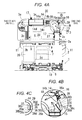
Fig. 4A or13A , an engine exhaust treatment device includes: an SCR catalyst case (3) housing an SCR catalyst (5); an SCR exhaust inlet pipe (14); and a urea water injector (16), with a nozzle portion (16a) of the urea water injector (16) directed toward an inside of the SCR exhaust inlet pipe (14). - As shown as an example in
Fig. 4B or13B , an exhaust deflector (36) is provided in the SCR exhaust inlet pipe (14) and the exhaust deflector (36) is mounted to an inner peripheral face (37) of the SCR exhaust inlet pipe (14) on an exhaust upstream side of the urea water injector (16) so that exhaust (15) flowing toward the nozzle portion (16a) of the urea water injector (16) is deflected by the exhaust deflector (36) and diverted from the nozzle portion (16a). - The exhaust deflector (36) may comprise an exhaust deflecting plate (36b), which may be substantially planar. The exhaust deflecting plate (36b) is preferably separated from the inner peripheral face (37) of the SCR exhaust inlet pipe (14), such that an exhaust passing clearance (38) is provided between the
exhaust deflecting plate 36b and the inner peripheral face (37) of the SCR exhaust inlet pipe (14). The exhaust deflector (36) may comprise the exhaust deflecting plate (36b) and paired side plates (36c), (36c), which may be bent from opposite side end edges of the exhaust deflecting plate (36b) toward the inner peripheral face (37) of the SCR exhaust inlet pipe (14). The exhaust deflector (36) may be formed in an angular U shape (from a view parallel to a passing direction of the exhaust (15)). - The invention according to
claim 1 exerts the following effects. - As shown as the example in
Fig. 4B or13B , the exhaust deflector (36) is provided in the SCR exhaust inlet pipe (14) and the exhaust deflector (36) is mounted to the inner peripheral face (37) of the SCR exhaust inlet pipe (14) on the exhaust upstream side of the urea water injector (16) so that exhaust (15) flowing toward the nozzle portion (16a) of the urea water injector (16) is deflected by the exhaust deflector (36) and diverted from the nozzle portion (16a). Therefore, the nozzle portion (16a) is less likely to take a direct hit from the exhaust (15) and the stick of the nozzle portion (16a) of the urea water injector (16) due to overheating can be suppressed. - As shown in
Fig. 4B or13B , the exhaust deflector (36) is mounted to the inner peripheral face (37) of the SCR exhaust inlet pipe (14) on the exhaust upstream side of the urea water injector (16) so that exhaust (15) flowing toward the nozzle portion (16a) of the urea water injector (16) is deflected by the exhaust deflector (36) and diverted from the nozzle portion (16a). Therefore, the nozzle portion (16a) can be disposed in the SCR exhaust inlet pipe (14) or disposed closer to the inside of the SCR exhaust inlet pipe (14), which improves penetration of the urea water (18) in the SCR exhaust inlet pipe (14) to improve ease of mixing of the urea water (18) and the exhaust (15). - In other words, in order to prevent the exhaust from directly hitting the nozzle portion of the urea water injector without mounting the exhaust deflector to the inner peripheral face of the SCR exhaust inlet pipe, a urea water injection passage needs to be led radially outward from an SCR exhaust inlet pipe and a nozzle portion needs to be disposed at a led-out end. In this case, however, the nozzle portion is far from the SCR exhaust inlet pipe, which reduces penetration of urea water in the SCR exhaust inlet pipe to reduce ease of mixing of the urea water and exhaust. In the invention, on the other hand, the nozzle portion (16a) can be disposed in the SCR exhaust inlet pipe (14) or disposed closer to the inside of the SCR exhaust inlet pipe (14), which prevents such problems.
- An invention according to
claim 2 exerts the following effect in addition to the effects of the invention according toclaim 1. - As shown as the example in
Fig. 4B or13B , the exhaust deflector (36) includes an exhaust deflecting face (36a) and the exhaust deflecting face (36a) is formed so as to gradually separate from the inner peripheral face (37) of the SCR exhaust inlet pipe (14) as the exhaust deflecting face (36a) extends from the exhaust upstream side toward an exhaust downstream side. Therefore, the exhaust deflecting face (36a) gently deflects the exhaust (15) to thereby suppress the increase in the back pressure. - In other words, if the exhaust deflecting face is orthogonal to a direction of the exhaust, the exhaust inverts on the exhaust deflecting face toward the exhaust upstream side and the increase in the back pressure cannot be suppressed. In the invention, on the other hand, the exhaust deflecting face (36a) gently deflects the exhaust (15), which suppresses occurrence of inversion of the exhaust (15) and the above-described problem.
- An invention according to
claim 3 exerts the following effect in addition to the effect of the invention according toclaim 2. - As shown as the example in
Fig. 4B or13B , an exhaust passing clearance (38) is provided between the exhaust deflecting plate (36b) and the inner peripheral face (37) of the SCR exhaust inlet pipe (14). Therefore, the exhaust (15) passes through the exhaust passing clearance (38) to thereby suppress the problem of the accumulation of the urea crystal between the exhaust deflecting plate (36b) and the inner peripheral face (37) of the SCR exhaust inlet pipe (14). - In other words, if exhaust does not pass between an exhaust guide plate and an inner peripheral face of an SCR exhaust inlet pipe, the exhaust stagnates to cause accumulation of urea crystal between the exhaust guide plate and the inner peripheral face. In the invention, on the other hand, the exhaust (15) passes through the exhaust passing clearance (38) and does not stagnate, which suppresses the above-described problem.
- An invention according to
claim 4 exerts the following effect in addition to the effect of the invention according toclaim 3. - As shown as the example in
Fig. 4B or13B , the exhaust passing clearance (38) is formed so that an opening area of a start opening portion (38a) on the exhaust upstream side is smaller than an opening area of an end opening portion (38b) on the exhaust downstream side. Therefore, it is possible to limit an amount of the exhaust (15) passing through the exhaust passing clearance (38) to thereby suppress the problem of occurrence of the stick of the nozzle portion (16a) of the urea water injector (16) due to the heat of the exhaust (15) passing through the exhaust passing clearance (38). - In other words, if an excessive amount of exhaust passes through an exhaust passing clearance, surplus exhaust passing through the exhaust passing clearance collides with a nozzle portion of a urea water injector to thereby cause stick of the nozzle portion due to overheating. In the invention, on the other hand, the opening area of the start opening portion (38a) of the exhaust passing clearance (38) is smaller and therefore, it is possible to limit the amount of the exhaust passing through the exhaust passing clearance (38) to thereby suppress the above-described problem.
- An invention according to
claim 5 exerts the following effect in addition to the effect(s) of the invention according to any one ofclaims 1 to 4. - As shown as an example in
Fig. 2 or11 , the SCR catalyst case (3) is at a position displaced diagonally forward and upward from the DOC case (2). As shown as an example inFig. 1 or10 , the urea water mixing pipe portion (14a) is formed straight in an orientation along longitudinal directions of central axes (2e) and (3d) of the DOC case (2) and the SCR catalyst case (3) and disposed behind the SCR catalyst case (3) and above the DOC case (2). Therefore, the DOC case (2), the SCR catalyst case (3), and the urea water mixing pipe portion (14a) do not cross each other and the DOC case (2), the SCR catalyst case (3), and the urea water mixing pipe portion (14a) can be disposed in the small space. - An invention according to
claim 6 exerts the following effect in addition to the effect of the invention according toclaim 5. - As shown as the example in
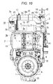
Fig. 1 or10 , a highest portion (2b) of a peripheral face of the DOC case (2) is disposed at a lower position than a lowest portion (3b) of a peripheral face of the SCR catalyst case (3) and the urea water mixing pipe portion (14a) is disposed at a position overlapping a highest portion (3c) of the peripheral face of the SCR catalyst case (3) from a view parallel to a front-back direction. Therefore, the urea water mixing pipe portion (14a) is disposed at a sufficient upward distance from the highest portion (2b) of the peripheral face of the DOC case (2), which suppresses the overheating of the urea water mixing pipe portion (14a) by the heat generation of the DOC (26). If the urea water mixing pipe portion (14a) is overheated, the accumulation of the urea crystal may be caused in the urea water mixing pipe portion (14a). -
-
Fig. 1 is a back view of a diesel engine according to a first embodiment of the present invention; -
Fig. 2 is a right side view of the engine inFig. 1 ; -
Fig. 3 is a left side view of the engine inFig. 1 ; -
Figs. 4 A to 4C are drawings for explaining a main part of the engine inFig. 1 , whereinFig. 4A is a back view of an upper portion of the engine inFig. 1 with a part of piping shown in a vertical sectional view,Fig. 4B is an enlarged view of part B ofFig. 4A, and Fig. 4C is a sectional view taken along line C-C inFig. 4B ; -
Fig. 5 is a left side view of the upper portion of the engine inFig. 1 with parts of an SCR catalyst case and an exhaust inlet pipe shown in vertical sectional views; -
Fig. 6 is a sectional back view of the engine inFig. 1 taken at a position of the SCR catalyst case; -
Fig. 7 is a plan view of the engine inFig. 1 ; -
Fig. 8 is a front view of the engine inFig. 1 ; -
Fig. 9 is a diagram for explaining a principle of a slip joint portion used in the engine inFig. 1 ; -
Fig. 10 is a back view of a diesel engine according to a second embodiment of the invention; -
Fig. 11 is a right side view of the engine inFig. 10 ; -
Fig. 12 is a left side view of the engine inFig. 10 ; -
Figs. 13A to 13C are drawings for explaining a main part of the engine inFig. 10 , whereinFig. 13A is a back view of an upper portion of the engine inFig. 10 with a part of piping shown in a vertical sectional view,Fig. 13B is an enlarged view of part B ofFig. 13A, and Fig. 13C is a sectional view taken along line C-C inFig. 13B ; -
Fig. 14 is a plan view of the engine inFig. 10 ; -
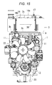
Fig. 15 is a front view of the engine inFig. 10 ; and -
Fig. 16 is a right side view of a variation of the engine inFig. 10 . -
Figs. 1 to 9 are drawings for explaining a diesel engine according to a first embodiment of the present invention andFigs. 10 to 16 are drawings for explaining a diesel engine according to a second embodiment of the invention. In each of the embodiments, a vertical straight multicylinder diesel engine will be described. - A general outline of the engine according to the first embodiment is as follows. The engine is mounted with an exhaust treatment device.
- As shown in
Fig. 4A , the exhaust treatment device includes an SCR catalyst case (3) housing an SCR catalyst (5), an SCR exhaust inlet pipe (14), and a urea water injector (16) and the urea water injector (16) is directed toward an inside of the SCR exhaust inlet pipe (14). - The exhaust treatment device can carry out reduction of NOx in exhaust (15) by use of the SCR catalyst (5). NOx is an abbreviation of nitrogen oxides.
- As shown in
Fig. 4A , in the SCR catalyst case (3), the SCR catalyst (5) is housed on an exhaust upstream side and an ammonia purification oxidation catalyst (27) is housed on an exhaust downstream side to thereby prevent ammonia slip. SCR is an abbreviation of selective catalytic reduction. - As shown in
Fig. 4B , an exhaust deflector (36) is provided in the SCR exhaust inlet pipe (14) and the exhaust deflector (36) is mounted to an inner peripheral face (37) of the SCR exhaust inlet pipe (14) on the exhaust upstream side of the urea water injector (16) so that the exhaust (15) flowing toward a nozzle portion (16a) of the urea water injector (16) is deflected by the exhaust deflector (36) and diverted from the nozzle portion (16a). - Therefore, the nozzle portion (16a) is less likely to take a direct hit from the exhaust (15) and stick of the nozzle portion (16a) of the urea water injector (16) due to overheating can be suppressed.
- Moreover, the nozzle portion (16a) can be disposed in the SCR exhaust inlet pipe (14) or disposed closer to the inside of the SCR exhaust inlet pipe (14), which improves penetration of urea water (18) in the SCR exhaust inlet pipe (14) to increase ease of mixing of the urea water (18) and the exhaust (15).
- As shown as an example in
Fig. 4B , the exhaust deflector (36) has an exhaust deflecting face (36a) and the exhaust deflecting face (36a) is formed to gradually separate from the inner peripheral face (37) of the SCR exhaust inlet pipe (14) as it extends from the exhaust upstream side toward the exhaust downstream side. - Therefore, the exhaust deflecting face (36a) gently deflects the exhaust (15) to thereby suppress increase in back pressure.
- As shown in
Fig. 4B , the exhaust deflector (36) has an exhaust deflecting plate (36b), the exhaust deflecting plate (36b) is separated from the inner peripheral face (37) of the SCR exhaust inlet pipe (14), and one of front and back faces of the exhaust deflecting plate (36b) and not facing the inner peripheral face (37) of the SCR exhaust inlet pipe (14) serves as the exhaust deflecting face (36a). - Between the exhaust deflecting plate (36b) and the inner peripheral face (37) of the SCR exhaust inlet pipe (14), an exhaust passing clearance (38) is provided.
- Therefore, the exhaust (15) passes through the exhaust passing clearance (38) and it is possible to suppress a problem of accumulation of urea crystal between the exhaust deflecting plate (36b) and the inner peripheral face (37) of the SCR exhaust inlet pipe (14).
- Moreover, the exhaust passing clearance (38) is formed so that an opening area of a start opening portion (38a) on the exhaust upstream side is smaller than an opening area of an end opening portion (38b) on the exhaust downstream side.
- Therefore, it is possible to limit an amount of the exhaust (15) passing through the exhaust passing clearance (38) with the start opening portion (38a) to thereby suppress a problem of occurrence of stick of the nozzle portion (16a) of the urea water injector (16) due to the exhaust (15) passing through the exhaust passing clearance (38).
- As shown in
Figs. 4B and 4C , the exhaust deflector (36) has the exhaust deflecting plate (36b) and paired side plates (36c), (36c) and the side plates (36c), (36c) are bent from opposite side end edges of the exhaust deflecting plate (36b) toward the inner peripheral face (37) of the SCR exhaust inlet pipe (14). As shown inFig. 4C , the exhaust deflector (36) is formed in an angular U shape from a view parallel to a passing direction of the exhaust (15). Bent end portions (36d), (36d) of the side plates (36c), (36c) pass through a pipe wall of the SCR exhaust inlet pipe (14) to be welded on an outer peripheral face of the SCR exhaust inlet pipe (14) so that the exhaust deflector (36) is supported on the SCR exhaust inlet pipe (14). An outer peripheral face of the SCR exhaust inlet pipe (14) and the bent end portions (36d), (36d) of the side plates (36c), (36c) are covered with a protective cover (39) and heat insulating material (not shown) is filled inside the protective cover (39). - Stainless steel plates are used for the SCR exhaust inlet pipe (14) and the exhaust deflector (36), an iron plate is used for the protective cover (39), and glass wool is used for the heat insulating material.
- As shown in
Fig. 1 , the exhaust treatment device has a DOC case (2) housing a DOC (26) and the SCR catalyst case (3) is disposed in an orientation along a longitudinal direction of a central axis (2e) of the DOC case (2). - As shown in
Fig. 2 , if a horizontal direction is a front-back direction with one side of the front-back direction being a front side and the other side being a back side from a view parallel to the longitudinal direction of the central axis (2e) of the DOC case (2), the SCR catalyst case (3) is disposed at a position displaced diagonally forward and upward from the DOC case (2). - As shown in
Fig. 4A , the SCR exhaust inlet pipe (14) has a urea water mixing pipe portion (14a), the urea water mixing pipe portion (14a) is a pipe portion, where the exhaust (15) led out from the DOC case (2) and the urea water (18) injected from the nozzle portion (16a) of the urea water injector (16) are mixed, and is formed straight in an orientation along the central axis (2e) of the DOC case (2) and a central axis (3d) of the SCR catalyst case (3). - As shown in
Figs. 1 and2 , the urea water mixing pipe portion (14a) is disposed behind the SCR catalyst case (3) and above the DOC case (2). - Therefore, the DOC case (2), the SCR catalyst case (3), and the urea water mixing pipe portion (14a) do not cross each other and the DOC case (2), the SCR catalyst case (3), and the urea water mixing pipe portion (14a) can be disposed in a small space.
- As shown in
Fig. 7 , the urea water mixing pipe portion (14a) is disposed directly above the DOC case (2). In other words, the urea water mixing pipe portion (14a) is disposed at a position overlapping an upper face of the DOC case (2) when seen in a direction parallel to a vertical direction in a plan view. - As shown in
Fig. 1 , the DOC (26) is housed on the exhaust upstream side and a DPF (4) is housed on the exhaust downstream side in the DOC case (2). DOC is an abbreviation of a diesel oxidation catalyst and DPF is an abbreviation of a diesel particulate filter. A different DOC from the DOC (26) on the exhaust upstream side may be used in place of the DPF (4) so that the plurality of DOCs are arranged and housed in series. - As shown in
Figs. 1 and2 , each of the DOC case (2) and the SCR catalyst case (3) has a cylindrical peripheral wall and opposite end walls closing opposite ends of the cylindrical peripheral wall and the central axis (2e) or (3d) is oriented in a longitudinal direction of the DOC case (2) or the SCR catalyst case (3). The cylindrical peripheral wall of the DOC case (2) is in an elongated circular cylindrical shape having a greater diameter in the vertical direction than a diameter in the front-back direction and the cylindrical peripheral wall of the SCR catalyst case (3) is in a circular cylindrical shape with a uniform diameter. - As shown in
Fig. 1 , a highest portion (2b) of a peripheral face of the DOC case (2) is disposed at a lower position than a lowest portion (3b) of a peripheral face of the SCR catalyst case (3). The urea water mixing pipe portion (14a) is disposed at a position overlapping a highest portion (3c) of the peripheral face of the SCR catalyst case (3) from a view parallel to the front-back direction. - Therefore, the urea water mixing pipe portion (14a) is disposed at a sufficient upward distance from the highest portion (2b) of the peripheral face of the DOC case (2), which suppresses a problem of overheating of the urea water mixing pipe portion (14a) by heat generation of the DOC (26).
- As shown in
Fig. 4B , the urea water injector (16) is mounted to a middle portion of a curved pipe portion (14b) forming the SCR exhaust inlet pipe (14). As shown inFig. 4A , the nozzle portion (16a) is slightly oriented toward the urea water mixing pipe portion (14a) rather than oriented in a radial direction of the curved pipe portion (14b). - As shown in
Fig. 4A , a mixer plate (30) is provided in the urea water mixing pipe portion (14a) of the SCR exhaust inlet pipe (14) to facilitate mixing of the exhaust (15) and the urea water (18). - As shown in
Figs. 4A and 4B , the exhaust deflector (36) is mounted to a start portion on the exhaust upstream side of the curved pipe portion (14b) forming the SCR exhaust inlet pipe (14). - An outline of the engine mounted with the exhaust treatment device is as follows.
- As shown in
Fig. 2 , a longitudinal direction of a crankshaft central axis (19) of an engine main body (1) is defined as a front-back direction with one side of the front-back direction being a front side and the other side being a back side. As shown inFig. 1 , from a view parallel to the front-back direction, a width direction of the engine main body (1) which is a horizontal direction is defined as a lateral direction. - As shown in
Fig. 2 , a cylinder head (20) is mounted to an upper portion of a cylinder block (12), a cylinder head cover (7) is mounted to an upper portion of the cylinder head (20), a water pump case (21) is mounted to a front portion of the cylinder block (12), an engine cooling fan (22) is disposed in front of the water pump case (21), a flywheel housing (6) is disposed behind the cylinder block (12), and an oil pan (23) is mounted to a lower portion of the cylinder block (12). - As shown in
Fig. 2 , an intake manifold (24) is mounted to one side in the lateral direction of the cylinder head (20). As shown inFig. 3 , an exhaust manifold (25) is mounted to the other side in the lateral direction of the cylinder head (20). - As shown as the example in
Figs. 1 to 3 , because the DOC case (2) and the SCR catalyst case (3) are mounted to the engine main body (1), the engine main body (1), the DOC case (2), and the SCR catalyst case (3) can be disposed compactly. If the engine main body (1) is mounted to a machine to be mounted with the engine, the DOC case (2) and the SCR catalyst case (3) are mounted at the same time to the machine to be mounted with the engine, which facilitates mounting to the machine to be mounted with the engine. - As shown in
Fig. 2 , the DOC case (2) is disposed at a position displaced diagonally backward and upward from the flywheel housing (6). - The DOC case (2) is disposed directly behind the cylinder head cover (7). In other words, as shown in
Fig. 1 , the DOC case (2) is disposed at the position overlapping a back face of the cylinder head cover (7) when seen in the direction parallel to the front-back direction in a back view. - As shown in
Fig. 2 , the SCR catalyst case (3) is disposed directly above the cylinder head cover (7). In other words, as shown inFig. 7 , the SCR catalyst case (3) is disposed at a position overlapping an upper face of the cylinder head cover (7) when seen in the direction parallel to the vertical direction in a plan view. - As shown in
Figs. 1 to 3 , the engine main body (1) includes a DOC base bracket (8), an SCR base bracket (9), a DOC support base (10), and an SCR support stay (11). - Onto the DOC base bracket (8), the DOC case (2) is placed and mounted.
- Onto the SCR base bracket (9), the SCR catalyst case (3) is placed and mounted.
- The DOC support base (10) is provided to an upper portion of the flywheel housing (6), the flywheel housing (6) is a cast disposed at a back end portion of the cylinder block (12), the DOC support base (10) is formed by a protruding portion of the flywheel housing (6) by casting, and the DOC base bracket (8) is placed and mounted onto the DOC support base (10).
- The flywheel housing (6) and a transmission case (not shown) connected to the flywheel housing (6) are used together as a main frame of a traveling machine body such as a tractor.
- The SCR support stay (11) has an upper end portion fixed to the SCR base bracket (9) and a lower end portion fixed to an engine main body part (13) at a higher position than the cylinder block (12).
- With this structure, the DOC case (2) can be firmly supported onto the engine main body (1) by the DOC support base (10) with high rigidity.
- Moreover, because the SCR support stay (11) has the upper end portion fixed to the SCR base bracket (9) and the lower end portion fixed to the engine main body part (13) at the higher position than the cylinder block (12), a vertical length of the SCR support stay (11) can be reduced and the SCR catalyst case (3) can be firmly supported onto the engine main body (1) by the SCR support stay (11) with high rigidity.
- The engine main body part (13) includes the intake manifold (24) shown in
Fig. 2 and an exhaust flange pipe (28) shown inFig. 3 . The exhaust flange pipe (28) is a pipe connecting an exhaust turbine (29a) of a supercharger (29) mounted to an upper portion of the exhaust manifold (25) and an exhaust inlet pipe (2d) of the DOC case (2). - As shown in
Fig. 7 , the SCR base bracket (9) has a front extension portion (9a) led out forward and the front extension portion (9a) is supported on the intake manifold (24) and an engine lifting plate (31) with a front support stay (9b) interposed therebetween. In this way, forward and backward swing of the SCR base bracket (9) is suppressed. - As shown in
Fig. 1 , the SCR exhaust inlet pipe (14) has slip joint portions (17) at opposite end portions. - As shown in
Fig. 9 , in principle, a slip joint portion (17) is formed so that pipe portions (17a), (17b) are fitted with each other to be able to slide for extension and contraction in a longitudinal direction and fixed at a predetermined sliding position of the extension and contraction by a fastening portion (17c). - The fastening portion (17c) is a fastening band and fixes the pipe portions (17a), (17b) by fastening. A clearance between the pipe portions (17a), (17b) is sealed with a gasket (17d).
- With this structure, by temporarily loosening the fastening by the slip joint portions (17) after the DOC case (2) and the SCR catalyst case (3) are mounted to the engine main body (1), stress caused at each portion of piping and the like by torsion or displacement is released and distortion of each portion of the piping and the like can be prevented.
- As shown in
Fig. 4A , an exhaust outlet pipe (2a) of the DOC case (2) is led out in a radial direction from a peripheral wall on one end side of the DOC case (2). - If one of the opposite end sides of the SCR catalyst case (3) and on the same side as the exhaust outlet pipe (2a) of the DOC case (2) is defined as one end side and an opposite side is defined as the other end side, an exhaust inlet pipe (3a) of the SCR catalyst case (3) is led out from a peripheral wall on the other end side to curve toward the one end side.
- The SCR exhaust inlet pipe (14) includes the curved pipe portion (14b) and the urea water mixing pipe portion (14a), the curved pipe portion (14b) is connected to an outlet end portion (2c) of the exhaust outlet pipe (2a) of the DOC case (2) and led out from the outlet end portion (2c) of the exhaust outlet pipe (2a) to curve toward the exhaust inlet pipe (3a) of the SCR catalyst case (3), the urea water mixing pipe portion (14a) is led out straight from an outlet end portion (14c) of the curved pipe portion (14b) toward the exhaust inlet pipe (3a) of the SCR catalyst case (3), and an outlet end portion (14d) of the urea water mixing pipe portion (14a) is connected to the exhaust inlet pipe (3a) of the SCR catalyst case (3).
- Therefore, the exhaust (15) does not invert in the exhaust outlet pipe (2a) of the DOC case (2), the exhaust inlet pipe (3a) of the SCR catalyst case (3), and the SCR exhaust inlet pipe (14), which reduces passing resistance of the exhaust (15) from the DOC case (2) into the SCR catalyst case (3) to thereby suppress increase in back pressure.
- Next, the second embodiment will be described.
- The second embodiment is different from the first embodiment in the following respects.
- As shown in
Figs. 10 to 12 , an engine main body (1) includes a DOC base bracket (8), an SCR base bracket (9), a DOC support base (10), and an SCR support stay (11). - Onto the DOC base bracket (8), a DOC case (2) is placed and mounted.
- Onto the SCR base bracket (9), an SCR catalyst case (3) is placed and mounted.
- The DOC support base (10) is provided to an upper portion of a flywheel housing (6), the flywheel housing (6) is a cast disposed at a back end portion of a cylinder block (12), the DOC support base (10) is formed by a protruding portion of the flywheel housing (6) by casting, and the DOC base bracket (8) is placed and mounted onto the DOC support base (10).
- The SCR support stay (11) has a lower portion fixed to the flywheel housing (6) and the DOC base bracket (8) and the SCR base bracket (9) is fixed to an upper end portion of the SCR support stay (11).
- In this way, the DOC case (2) can be firmly supported onto the engine main body (1) by the DOC support base (10) with high rigidity.
- Moreover, because the SCR support stay (11) has a lower portion fixed to the flywheel housing (6) and the DOC base bracket (8) and the SCR base bracket (9) is fixed to the upper end portion of the SCR support stay (11), the SCR catalyst case (3) can be supported on the flywheel housing (6) with high rigidity by the SCR support stay (11) and also on the DOC support base (10) with high rigidity by the SCR support stay (11) and the DOC base bracket (8). Therefore, the DOC case (2) can be firmly supported onto the engine main body (1).
- In a variation of the second embodiment shown in
Fig. 16 , the following structure is added to the basic example of the second embodiment shown inFigs. 10 to 15 . - In other words, an engine has a connector mounting plate (28), the connector mounting plate (28) is mounted to an SCR support stay (11), and connectors (32) for electronic components are mounted to the connector mounting plate (28). Therefore, the connector mounting plate (28) is less likely to vibrate and damage to the connectors (32) due to vibrations can be suppressed.
- All of the connectors (32) mounted to the connector mounting plate (28) are for the SCR catalyst (5) and are connectors for a urea water injector (16), an inlet NOx sensor (33), an outlet NOx sensor (34), and an exhaust temperature sensor (35) shown in
Fig. 10 . - Other structures of the basic example and the variation of the second embodiment are the same as those of the first embodiment and the same components in
Figs. 10 to 16 as those of the first embodiment are provided with the same reference numerals as inFigs. 1 to 9 .
Claims (6)
- An engine exhaust treatment device comprising: an SCR catalyst case (3) housing an SCR catalyst (5); an SCR exhaust inlet pipe (14); and a urea water injector (16), with a nozzle portion (16a) of the urea water injector (16) directed toward an inside of the SCR exhaust inlet pipe (14),
wherein, an exhaust deflector (36) is provided in the SCR exhaust inlet pipe (14) and the exhaust deflector (36) is mounted to an inner peripheral face (37) of the SCR exhaust inlet pipe (14) on an exhaust upstream side of the urea water injector (16) so that exhaust (15) flowing toward the nozzle portion (16a) of the urea water injector (16) is deflected by the exhaust deflector (36) and diverted from the nozzle portion (16a). - The engine exhaust treatment device according to claim 1,
wherein the exhaust deflector (36) includes an exhaust deflecting face (36a) and the exhaust deflecting face (36a) is formed so that its separation from the inner peripheral face (37) of the SCR exhaust inlet pipe (14) gradually increases as the exhaust deflecting face (36a) extends from the exhaust upstream side toward an exhaust downstream side. - The engine exhaust treatment device according to claim 2,
wherein the exhaust deflector (36) includes an exhaust deflecting plate (36b), the exhaust deflecting plate (36b) is separated from the inner peripheral face (37) of the SCR exhaust inlet pipe (14), and one of front and back faces of the exhaust deflecting plate (36b) not facing the inner peripheral face (37) of the SCR exhaust inlet pipe (14) is formed as the exhaust deflecting face (36a), and
an exhaust passing clearance (38) is provided between the exhaust deflecting plate (36b) and the inner peripheral face (37) of the SCR exhaust inlet pipe (14). - The engine exhaust treatment device according to claim 3,
wherein the exhaust passing clearance (38) is formed so that an opening area of a start opening portion (38a) on the exhaust upstream side is smaller than an opening area of an end opening portion (38b) on the exhaust downstream side. - The engine exhaust treatment device according to any one of claims 1 to 4 further comprising a DOC case (2) housing a DOC (26),
wherein the SCR catalyst case (3) is disposed in an orientation along a longitudinal direction of a central axis (2e) of the DOC case (2),
the SCR catalyst case (3) is disposed at a position displaced diagonally forward and upward from the DOC case (2), if a horizontal direction is a front-back direction with one side of the front-back direction being a front side and the other side being a back side from a view parallel to the longitudinal direction of the central axis (2e) of the DOC case (2),
the SCR exhaust inlet pipe (14) includes a urea water mixing pipe portion (14a), the urea water mixing pipe portion (14a) is a pipe portion where the exhaust (15) led out from the DOC case (2) and urea water (18) injected from the nozzle portion (16a) of the urea water injector (16) are mixed, and is formed straight in an orientation along longitudinal directions of the central axis (2e) of the DOC case (2) and a central axis (3d) of the SCR catalyst case (3), and
the urea water mixing pipe portion (14a) is disposed behind the SCR catalyst case (3) and above the DOC case (2). - The engine exhaust treatment device according to claim 5,
wherein a highest portion (2b) of a peripheral face of the DOC case (2) is disposed at a lower position than a lowest portion (3b) of a peripheral face of the SCR catalyst case (3) and the urea water mixing pipe portion (14a) is disposed at a position overlapping a highest portion (3c) of the peripheral face of the SCR catalyst case (3) from a view parallel to the front-back direction.
Applications Claiming Priority (1)
| Application Number | Priority Date | Filing Date | Title |
|---|---|---|---|
| JP2015067481A JP6423302B2 (en) | 2015-03-27 | 2015-03-27 | Engine exhaust treatment equipment |
Publications (2)
| Publication Number | Publication Date |
|---|---|
| EP3073079A1 true EP3073079A1 (en) | 2016-09-28 |
| EP3073079B1 EP3073079B1 (en) | 2018-03-14 |
Family
ID=54782614
Family Applications (1)
| Application Number | Title | Priority Date | Filing Date |
|---|---|---|---|
| EP15198029.9A Active EP3073079B1 (en) | 2015-03-27 | 2015-12-04 | Engine exhaust aftertreatment device |
Country Status (3)
| Country | Link |
|---|---|
| US (1) | US9863299B2 (en) |
| EP (1) | EP3073079B1 (en) |
| JP (1) | JP6423302B2 (en) |
Cited By (1)
| Publication number | Priority date | Publication date | Assignee | Title |
|---|---|---|---|---|
| EP4306779A1 (en) * | 2022-07-13 | 2024-01-17 | Yanmar Holdings Co., Ltd. | Exhaust gas rectifier and exhaust gas purification system |
Families Citing this family (2)
| Publication number | Priority date | Publication date | Assignee | Title |
|---|---|---|---|---|
| JP7086333B2 (en) * | 2018-01-30 | 2022-06-20 | 三菱ふそうトラック・バス株式会社 | Exhaust gas purification device |
| CN115419487B (en) * | 2022-11-07 | 2023-01-06 | 烟台鲁吉汽车科技有限公司 | Urea atomization equipment |
Citations (6)
| Publication number | Priority date | Publication date | Assignee | Title |
|---|---|---|---|---|
| US20090313979A1 (en) * | 2007-02-23 | 2009-12-24 | Hino Motors, Ltd. | Exhaust emission control device |
| US20100083641A1 (en) * | 2008-10-07 | 2010-04-08 | International Engine Intellectual Property Company, Llc | System and Method of LIquid Injection into a Gas Stream |
| DE102009046280A1 (en) * | 2009-11-02 | 2011-05-12 | Ford Global Technologies, LLC, Dearborn | Method for injecting liquid reducing agent into engine exhaust gas flow, involves injecting liquid reducing agent into exhaust gas flow by injection nozzle |
| WO2012047159A1 (en) * | 2010-10-06 | 2012-04-12 | Scania Cv Ab (Publ) | Arrangement for introducing a liquid medium into exhaust gases from a combustion engine |
| DE102012216676A1 (en) * | 2012-09-18 | 2014-03-20 | Robert Bosch Gmbh | Exhaust aftertreatment device for internal combustion engine, has baffle plate comprising jet impact surface that impinges liquid upon actuation of injection valve, where surface tapers in flow direction of exhaust gas in exhaust passage |
| JP2014148960A (en) | 2013-02-04 | 2014-08-21 | Mitsubishi Motors Corp | Vehicle exhaust purification device |
Family Cites Families (13)
| Publication number | Priority date | Publication date | Assignee | Title |
|---|---|---|---|---|
| JPH0621555B2 (en) * | 1989-02-27 | 1994-03-23 | 神鋼電機株式会社 | Ammonia mixing device in denitration device |
| JPH10511038A (en) * | 1995-06-28 | 1998-10-27 | シーメンス アクチエンゲゼルシヤフト | Method and apparatus for purifying catalyst from exhaust gas from combustion equipment |
| JP2006329010A (en) * | 2005-05-24 | 2006-12-07 | Toyota Motor Corp | Exhaust gas purification device for internal combustion engine |
| JP4785766B2 (en) * | 2007-02-09 | 2011-10-05 | 日野自動車株式会社 | Exhaust purification device |
| US8033104B2 (en) * | 2008-07-09 | 2011-10-11 | Ford Global Technologies, Llc | Selective catalytic reduction (SCR) catalyst injection systems |
| US20100186381A1 (en) * | 2009-01-26 | 2010-07-29 | Caterpillar Inc | Exhaust system thermal enclosure |
| US8460610B2 (en) * | 2009-12-22 | 2013-06-11 | Caterpillar Inc. | Canister aftertreatment module |
| US8621846B2 (en) * | 2010-03-02 | 2014-01-07 | GM Global Technology Operations LLC | Gas/liquid mixing device for diesel exhaust aftertreatment |
| JP5714844B2 (en) * | 2010-07-16 | 2015-05-07 | いすゞ自動車株式会社 | Exhaust gas purification device |
| US20120124983A1 (en) * | 2010-11-23 | 2012-05-24 | Haiping Hong | Exhaust system having reductant nozzle flow diverter |
| DE102011077155C5 (en) * | 2011-06-07 | 2022-04-14 | Robert Bosch Gmbh | exhaust system |
| JP6343119B2 (en) * | 2013-03-15 | 2018-06-13 | ヤンマー株式会社 | Combine engine equipment |
| JP2015086813A (en) * | 2013-10-31 | 2015-05-07 | 井関農機株式会社 | Tractor |
-
2015
- 2015-03-27 JP JP2015067481A patent/JP6423302B2/en active Active
- 2015-12-04 EP EP15198029.9A patent/EP3073079B1/en active Active
- 2015-12-09 US US14/963,316 patent/US9863299B2/en not_active Expired - Fee Related
Patent Citations (6)
| Publication number | Priority date | Publication date | Assignee | Title |
|---|---|---|---|---|
| US20090313979A1 (en) * | 2007-02-23 | 2009-12-24 | Hino Motors, Ltd. | Exhaust emission control device |
| US20100083641A1 (en) * | 2008-10-07 | 2010-04-08 | International Engine Intellectual Property Company, Llc | System and Method of LIquid Injection into a Gas Stream |
| DE102009046280A1 (en) * | 2009-11-02 | 2011-05-12 | Ford Global Technologies, LLC, Dearborn | Method for injecting liquid reducing agent into engine exhaust gas flow, involves injecting liquid reducing agent into exhaust gas flow by injection nozzle |
| WO2012047159A1 (en) * | 2010-10-06 | 2012-04-12 | Scania Cv Ab (Publ) | Arrangement for introducing a liquid medium into exhaust gases from a combustion engine |
| DE102012216676A1 (en) * | 2012-09-18 | 2014-03-20 | Robert Bosch Gmbh | Exhaust aftertreatment device for internal combustion engine, has baffle plate comprising jet impact surface that impinges liquid upon actuation of injection valve, where surface tapers in flow direction of exhaust gas in exhaust passage |
| JP2014148960A (en) | 2013-02-04 | 2014-08-21 | Mitsubishi Motors Corp | Vehicle exhaust purification device |
Cited By (1)
| Publication number | Priority date | Publication date | Assignee | Title |
|---|---|---|---|---|
| EP4306779A1 (en) * | 2022-07-13 | 2024-01-17 | Yanmar Holdings Co., Ltd. | Exhaust gas rectifier and exhaust gas purification system |
Also Published As
| Publication number | Publication date |
|---|---|
| JP2016186291A (en) | 2016-10-27 |
| JP6423302B2 (en) | 2018-11-14 |
| US9863299B2 (en) | 2018-01-09 |
| EP3073079B1 (en) | 2018-03-14 |
| US20160281564A1 (en) | 2016-09-29 |
Similar Documents
| Publication | Publication Date | Title |
|---|---|---|
| US9441514B2 (en) | Diesel engine | |
| US9718037B2 (en) | Mixing system for aftertreatment system | |
| US9920676B2 (en) | Mixer and emissions cleaning module | |
| US20150233276A1 (en) | Modular assembly for aftertreatment system | |
| EP2853704B1 (en) | Diesel engine | |
| EP2984313B1 (en) | Emissions cleaning module and mounting mechanism | |
| EP2984309B1 (en) | Support structure for mounting an emissions cleaning module | |
| CN110088443A (en) | Water conservancy diversion shade assembly | |
| EP3073079B1 (en) | Engine exhaust aftertreatment device | |
| US20150285200A1 (en) | Injector Mount | |
| WO2013112170A1 (en) | Cross style (4 port) ammonia gas injector | |
| WO2013154573A1 (en) | Mixing plate as stabilizer for ammonia gas injector | |
| JP6051154B2 (en) | diesel engine | |
| JP6391406B2 (en) | Exhaust gas purification device | |
| WO2014040701A8 (en) | Scr module | |
| JP2016186293A (en) | Exhaust treatment device of engine | |
| JP2016186292A (en) | Engine exhaust treatment equipment | |
| US20210164374A1 (en) | Exhaust aftertreatment component with bypass valve | |
| US11247173B1 (en) | Two-stage mixer | |
| JP7086333B2 (en) | Exhaust gas purification device | |
| US11300027B2 (en) | Mixer device, a use thereof and a method for mixing | |
| WO2013154571A1 (en) | Shrouded/downstream-pointing ammonia gas injector |
Legal Events
| Date | Code | Title | Description |
|---|---|---|---|
| PUAI | Public reference made under article 153(3) epc to a published international application that has entered the european phase |
Free format text: ORIGINAL CODE: 0009012 |
|
| AK | Designated contracting states |
Kind code of ref document: A1 Designated state(s): AL AT BE BG CH CY CZ DE DK EE ES FI FR GB GR HR HU IE IS IT LI LT LU LV MC MK MT NL NO PL PT RO RS SE SI SK SM TR |
|
| AX | Request for extension of the european patent |
Extension state: BA ME |
|
| 17P | Request for examination filed |
Effective date: 20170317 |
|
| RBV | Designated contracting states (corrected) |
Designated state(s): AL AT BE BG CH CY CZ DE DK EE ES FI FR GB GR HR HU IE IS IT LI LT LU LV MC MK MT NL NO PL PT RO RS SE SI SK SM TR |
|
| 17Q | First examination report despatched |
Effective date: 20170419 |
|
| REG | Reference to a national code |
Ref country code: DE Ref legal event code: R079 Ref document number: 602015008730 Country of ref document: DE Free format text: PREVIOUS MAIN CLASS: F01N0003200000 Ipc: F01N0003080000 |
|
| RIC1 | Information provided on ipc code assigned before grant |
Ipc: F01N 3/20 20060101ALI20170904BHEP Ipc: F01N 3/10 20060101ALI20170904BHEP Ipc: F01N 13/08 20100101ALI20170904BHEP Ipc: F01N 3/08 20060101AFI20170904BHEP Ipc: F01N 3/28 20060101ALI20170904BHEP Ipc: F01N 13/00 20100101ALI20170904BHEP |
|
| GRAP | Despatch of communication of intention to grant a patent |
Free format text: ORIGINAL CODE: EPIDOSNIGR1 |
|
| INTG | Intention to grant announced |
Effective date: 20171016 |
|
| GRAS | Grant fee paid |
Free format text: ORIGINAL CODE: EPIDOSNIGR3 |
|
| GRAA | (expected) grant |
Free format text: ORIGINAL CODE: 0009210 |
|
| AK | Designated contracting states |
Kind code of ref document: B1 Designated state(s): AL AT BE BG CH CY CZ DE DK EE ES FI FR GB GR HR HU IE IS IT LI LT LU LV MC MK MT NL NO PL PT RO RS SE SI SK SM TR |
|
| REG | Reference to a national code |
Ref country code: GB Ref legal event code: FG4D |
|
| REG | Reference to a national code |
Ref country code: CH Ref legal event code: EP Ref country code: AT Ref legal event code: REF Ref document number: 979100 Country of ref document: AT Kind code of ref document: T Effective date: 20180315 |
|
| REG | Reference to a national code |
Ref country code: IE Ref legal event code: FG4D |
|
| REG | Reference to a national code |
Ref country code: DE Ref legal event code: R096 Ref document number: 602015008730 Country of ref document: DE |
|
| REG | Reference to a national code |
Ref country code: NL Ref legal event code: MP Effective date: 20180314 |
|
| REG | Reference to a national code |
Ref country code: LT Ref legal event code: MG4D |
|
| PG25 | Lapsed in a contracting state [announced via postgrant information from national office to epo] |
Ref country code: HR Free format text: LAPSE BECAUSE OF FAILURE TO SUBMIT A TRANSLATION OF THE DESCRIPTION OR TO PAY THE FEE WITHIN THE PRESCRIBED TIME-LIMIT Effective date: 20180314 Ref country code: FI Free format text: LAPSE BECAUSE OF FAILURE TO SUBMIT A TRANSLATION OF THE DESCRIPTION OR TO PAY THE FEE WITHIN THE PRESCRIBED TIME-LIMIT Effective date: 20180314 Ref country code: NO Free format text: LAPSE BECAUSE OF FAILURE TO SUBMIT A TRANSLATION OF THE DESCRIPTION OR TO PAY THE FEE WITHIN THE PRESCRIBED TIME-LIMIT Effective date: 20180614 Ref country code: CY Free format text: LAPSE BECAUSE OF FAILURE TO SUBMIT A TRANSLATION OF THE DESCRIPTION OR TO PAY THE FEE WITHIN THE PRESCRIBED TIME-LIMIT Effective date: 20180314 Ref country code: LT Free format text: LAPSE BECAUSE OF FAILURE TO SUBMIT A TRANSLATION OF THE DESCRIPTION OR TO PAY THE FEE WITHIN THE PRESCRIBED TIME-LIMIT Effective date: 20180314 |
|
| REG | Reference to a national code |
Ref country code: AT Ref legal event code: MK05 Ref document number: 979100 Country of ref document: AT Kind code of ref document: T Effective date: 20180314 |
|
| PG25 | Lapsed in a contracting state [announced via postgrant information from national office to epo] |
Ref country code: RS Free format text: LAPSE BECAUSE OF FAILURE TO SUBMIT A TRANSLATION OF THE DESCRIPTION OR TO PAY THE FEE WITHIN THE PRESCRIBED TIME-LIMIT Effective date: 20180314 Ref country code: SE Free format text: LAPSE BECAUSE OF FAILURE TO SUBMIT A TRANSLATION OF THE DESCRIPTION OR TO PAY THE FEE WITHIN THE PRESCRIBED TIME-LIMIT Effective date: 20180314 Ref country code: LV Free format text: LAPSE BECAUSE OF FAILURE TO SUBMIT A TRANSLATION OF THE DESCRIPTION OR TO PAY THE FEE WITHIN THE PRESCRIBED TIME-LIMIT Effective date: 20180314 Ref country code: BG Free format text: LAPSE BECAUSE OF FAILURE TO SUBMIT A TRANSLATION OF THE DESCRIPTION OR TO PAY THE FEE WITHIN THE PRESCRIBED TIME-LIMIT Effective date: 20180614 Ref country code: GR Free format text: LAPSE BECAUSE OF FAILURE TO SUBMIT A TRANSLATION OF THE DESCRIPTION OR TO PAY THE FEE WITHIN THE PRESCRIBED TIME-LIMIT Effective date: 20180615 |
|
| PG25 | Lapsed in a contracting state [announced via postgrant information from national office to epo] |
Ref country code: RO Free format text: LAPSE BECAUSE OF FAILURE TO SUBMIT A TRANSLATION OF THE DESCRIPTION OR TO PAY THE FEE WITHIN THE PRESCRIBED TIME-LIMIT Effective date: 20180314 Ref country code: AL Free format text: LAPSE BECAUSE OF FAILURE TO SUBMIT A TRANSLATION OF THE DESCRIPTION OR TO PAY THE FEE WITHIN THE PRESCRIBED TIME-LIMIT Effective date: 20180314 Ref country code: IT Free format text: LAPSE BECAUSE OF FAILURE TO SUBMIT A TRANSLATION OF THE DESCRIPTION OR TO PAY THE FEE WITHIN THE PRESCRIBED TIME-LIMIT Effective date: 20180314 Ref country code: PL Free format text: LAPSE BECAUSE OF FAILURE TO SUBMIT A TRANSLATION OF THE DESCRIPTION OR TO PAY THE FEE WITHIN THE PRESCRIBED TIME-LIMIT Effective date: 20180314 Ref country code: EE Free format text: LAPSE BECAUSE OF FAILURE TO SUBMIT A TRANSLATION OF THE DESCRIPTION OR TO PAY THE FEE WITHIN THE PRESCRIBED TIME-LIMIT Effective date: 20180314 Ref country code: NL Free format text: LAPSE BECAUSE OF FAILURE TO SUBMIT A TRANSLATION OF THE DESCRIPTION OR TO PAY THE FEE WITHIN THE PRESCRIBED TIME-LIMIT Effective date: 20180314 Ref country code: ES Free format text: LAPSE BECAUSE OF FAILURE TO SUBMIT A TRANSLATION OF THE DESCRIPTION OR TO PAY THE FEE WITHIN THE PRESCRIBED TIME-LIMIT Effective date: 20180314 |
|
| PG25 | Lapsed in a contracting state [announced via postgrant information from national office to epo] |
Ref country code: SK Free format text: LAPSE BECAUSE OF FAILURE TO SUBMIT A TRANSLATION OF THE DESCRIPTION OR TO PAY THE FEE WITHIN THE PRESCRIBED TIME-LIMIT Effective date: 20180314 Ref country code: CZ Free format text: LAPSE BECAUSE OF FAILURE TO SUBMIT A TRANSLATION OF THE DESCRIPTION OR TO PAY THE FEE WITHIN THE PRESCRIBED TIME-LIMIT Effective date: 20180314 Ref country code: AT Free format text: LAPSE BECAUSE OF FAILURE TO SUBMIT A TRANSLATION OF THE DESCRIPTION OR TO PAY THE FEE WITHIN THE PRESCRIBED TIME-LIMIT Effective date: 20180314 Ref country code: SM Free format text: LAPSE BECAUSE OF FAILURE TO SUBMIT A TRANSLATION OF THE DESCRIPTION OR TO PAY THE FEE WITHIN THE PRESCRIBED TIME-LIMIT Effective date: 20180314 |
|
| REG | Reference to a national code |
Ref country code: DE Ref legal event code: R097 Ref document number: 602015008730 Country of ref document: DE |
|
| PG25 | Lapsed in a contracting state [announced via postgrant information from national office to epo] |
Ref country code: PT Free format text: LAPSE BECAUSE OF FAILURE TO SUBMIT A TRANSLATION OF THE DESCRIPTION OR TO PAY THE FEE WITHIN THE PRESCRIBED TIME-LIMIT Effective date: 20180716 |
|
| PLBE | No opposition filed within time limit |
Free format text: ORIGINAL CODE: 0009261 |
|
| STAA | Information on the status of an ep patent application or granted ep patent |
Free format text: STATUS: NO OPPOSITION FILED WITHIN TIME LIMIT |
|
| PG25 | Lapsed in a contracting state [announced via postgrant information from national office to epo] |
Ref country code: DK Free format text: LAPSE BECAUSE OF FAILURE TO SUBMIT A TRANSLATION OF THE DESCRIPTION OR TO PAY THE FEE WITHIN THE PRESCRIBED TIME-LIMIT Effective date: 20180314 |
|
| 26N | No opposition filed |
Effective date: 20181217 |
|
| PG25 | Lapsed in a contracting state [announced via postgrant information from national office to epo] |
Ref country code: SI Free format text: LAPSE BECAUSE OF FAILURE TO SUBMIT A TRANSLATION OF THE DESCRIPTION OR TO PAY THE FEE WITHIN THE PRESCRIBED TIME-LIMIT Effective date: 20180314 |
|
| REG | Reference to a national code |
Ref country code: CH Ref legal event code: PL |
|
| PG25 | Lapsed in a contracting state [announced via postgrant information from national office to epo] |
Ref country code: LU Free format text: LAPSE BECAUSE OF NON-PAYMENT OF DUE FEES Effective date: 20181204 Ref country code: MC Free format text: LAPSE BECAUSE OF FAILURE TO SUBMIT A TRANSLATION OF THE DESCRIPTION OR TO PAY THE FEE WITHIN THE PRESCRIBED TIME-LIMIT Effective date: 20180314 |
|
| REG | Reference to a national code |
Ref country code: IE Ref legal event code: MM4A |
|
| REG | Reference to a national code |
Ref country code: BE Ref legal event code: MM Effective date: 20181231 |
|
| PG25 | Lapsed in a contracting state [announced via postgrant information from national office to epo] |
Ref country code: IE Free format text: LAPSE BECAUSE OF NON-PAYMENT OF DUE FEES Effective date: 20181204 |
|
| PG25 | Lapsed in a contracting state [announced via postgrant information from national office to epo] |
Ref country code: BE Free format text: LAPSE BECAUSE OF NON-PAYMENT OF DUE FEES Effective date: 20181231 |
|
| PG25 | Lapsed in a contracting state [announced via postgrant information from national office to epo] |
Ref country code: LI Free format text: LAPSE BECAUSE OF NON-PAYMENT OF DUE FEES Effective date: 20181231 Ref country code: CH Free format text: LAPSE BECAUSE OF NON-PAYMENT OF DUE FEES Effective date: 20181231 |
|
| PG25 | Lapsed in a contracting state [announced via postgrant information from national office to epo] |
Ref country code: MT Free format text: LAPSE BECAUSE OF NON-PAYMENT OF DUE FEES Effective date: 20181204 |
|
| PG25 | Lapsed in a contracting state [announced via postgrant information from national office to epo] |
Ref country code: TR Free format text: LAPSE BECAUSE OF FAILURE TO SUBMIT A TRANSLATION OF THE DESCRIPTION OR TO PAY THE FEE WITHIN THE PRESCRIBED TIME-LIMIT Effective date: 20180314 |
|
| PG25 | Lapsed in a contracting state [announced via postgrant information from national office to epo] |
Ref country code: HU Free format text: LAPSE BECAUSE OF FAILURE TO SUBMIT A TRANSLATION OF THE DESCRIPTION OR TO PAY THE FEE WITHIN THE PRESCRIBED TIME-LIMIT; INVALID AB INITIO Effective date: 20151204 Ref country code: MK Free format text: LAPSE BECAUSE OF NON-PAYMENT OF DUE FEES Effective date: 20180314 |
|
| PG25 | Lapsed in a contracting state [announced via postgrant information from national office to epo] |
Ref country code: IS Free format text: LAPSE BECAUSE OF FAILURE TO SUBMIT A TRANSLATION OF THE DESCRIPTION OR TO PAY THE FEE WITHIN THE PRESCRIBED TIME-LIMIT Effective date: 20180714 |
|
| PGFP | Annual fee paid to national office [announced via postgrant information from national office to epo] |
Ref country code: DE Payment date: 20251028 Year of fee payment: 11 |
|
| PGFP | Annual fee paid to national office [announced via postgrant information from national office to epo] |
Ref country code: GB Payment date: 20251030 Year of fee payment: 11 |
|
| PGFP | Annual fee paid to national office [announced via postgrant information from national office to epo] |
Ref country code: FR Payment date: 20251110 Year of fee payment: 11 |