EP3072822A1 - Debris separator for label tape - Google Patents
Debris separator for label tape Download PDFInfo
- Publication number
- EP3072822A1 EP3072822A1 EP15200092.3A EP15200092A EP3072822A1 EP 3072822 A1 EP3072822 A1 EP 3072822A1 EP 15200092 A EP15200092 A EP 15200092A EP 3072822 A1 EP3072822 A1 EP 3072822A1
- Authority
- EP
- European Patent Office
- Prior art keywords
- debris
- label
- label tape
- circumferential surface
- web
- Prior art date
- Legal status (The legal status is an assumption and is not a legal conclusion. Google has not performed a legal analysis and makes no representation as to the accuracy of the status listed.)
- Withdrawn
Links
- 239000000463 material Substances 0.000 claims abstract description 22
- 238000001514 detection method Methods 0.000 claims description 12
- 239000000853 adhesive Substances 0.000 claims description 7
- 230000001070 adhesive effect Effects 0.000 claims description 7
- 238000000926 separation method Methods 0.000 description 15
- 238000011144 upstream manufacturing Methods 0.000 description 14
- 230000000712 assembly Effects 0.000 description 7
- 238000000429 assembly Methods 0.000 description 7
- 230000004048 modification Effects 0.000 description 3
- 238000012986 modification Methods 0.000 description 3
- 239000011248 coating agent Substances 0.000 description 1
- 238000000576 coating method Methods 0.000 description 1
- 239000002131 composite material Substances 0.000 description 1
- 239000003550 marker Substances 0.000 description 1
- 230000002093 peripheral effect Effects 0.000 description 1
- 238000005096 rolling process Methods 0.000 description 1
Images







Classifications
-
- B—PERFORMING OPERATIONS; TRANSPORTING
- B32—LAYERED PRODUCTS
- B32B—LAYERED PRODUCTS, i.e. PRODUCTS BUILT-UP OF STRATA OF FLAT OR NON-FLAT, e.g. CELLULAR OR HONEYCOMB, FORM
- B32B43/00—Operations specially adapted for layered products and not otherwise provided for, e.g. repairing; Apparatus therefor
- B32B43/006—Delaminating
-
- B—PERFORMING OPERATIONS; TRANSPORTING
- B65—CONVEYING; PACKING; STORING; HANDLING THIN OR FILAMENTARY MATERIAL
- B65C—LABELLING OR TAGGING MACHINES, APPARATUS, OR PROCESSES
- B65C9/00—Details of labelling machines or apparatus
- B65C9/0006—Removing backing sheets
-
- B—PERFORMING OPERATIONS; TRANSPORTING
- B65—CONVEYING; PACKING; STORING; HANDLING THIN OR FILAMENTARY MATERIAL
- B65C—LABELLING OR TAGGING MACHINES, APPARATUS, OR PROCESSES
- B65C9/00—Details of labelling machines or apparatus
- B65C9/0015—Preparing the labels or articles, e.g. smoothing, removing air bubbles
-
- B—PERFORMING OPERATIONS; TRANSPORTING
- B31—MAKING ARTICLES OF PAPER, CARDBOARD OR MATERIAL WORKED IN A MANNER ANALOGOUS TO PAPER; WORKING PAPER, CARDBOARD OR MATERIAL WORKED IN A MANNER ANALOGOUS TO PAPER
- B31D—MAKING ARTICLES OF PAPER, CARDBOARD OR MATERIAL WORKED IN A MANNER ANALOGOUS TO PAPER, NOT PROVIDED FOR IN SUBCLASSES B31B OR B31C
- B31D1/00—Multiple-step processes for making flat articles ; Making flat articles
- B31D1/02—Multiple-step processes for making flat articles ; Making flat articles the articles being labels or tags
- B31D1/021—Making adhesive labels having a multilayered structure, e.g. provided on carrier webs
Definitions
- the present invention generally relates to a label separator and a label printing system.
- a composite label tape is comprised of a carrier web and label material releasably adhered by an adhesive to the carrier web.
- the label material includes labels and residues or debris that surround each label.
- Each label is removed from the carrier web, leaving the surrounding residues on the web, and is applied to a product surface.
- Japanese Patent Publication No. 2006-181860 discloses one type of residue separator configured to separate the residue material from the carrier web.
- the apparatus comprises a mechanism which includes a separator member that peels the residues of the label material from the web. The separator member is effective in preventing the labels from being peeled together with the residue material.
- Fig. 14 illustrates the label tape when the residues are peeled.
- the label tape includes a web 9, half cut labels 10 and a residue 11, which are attached on surface of the web 9 by means of an adhesive.
- the residues include a portion 11a that extends in a direction parallel to a direction in which the label tape is paid out.
- the portion 11a is first peeled substantially in the direction in which the label tape is paid out.
- a portion 11b extends substantially in a direction perpendicular to the residue 11a and begins to be peeled off at its longitudinal ends. When the portion 11b leaves the web 9, unpleasant noise occurs. If the portion 11 is strongly adheres to the web 9, the portion 11b may break at its middle portion 11c.
- the present invention was made to solve the drawbacks of conventional apparatus for removing residues of the label material of a half cut label tape.
- An object of the invention is to provide a label separator and a label printing system that do not make unpleasant noise.
- a debris separator pre-separates debris from a label tape (8), the label tape including a carrier web (9) and a label material, the label material being half cut into labels and debris (11) that surround all around individual labels (10).
- the label tape (8) is transported in a path (36).
- a first roller is disposed in the path (36), extends in a direction, and is covered with an elastic member.
- a second roller is disposed in the path (36), extends parallel to the first roller, and includes elastic members (35) angularly disposed on the second roller.
- the elastic members have circumferential surfaces.
- a controller controls the first and second rotatable bodies. The first and second rollers rotate with the label tape (8) sandwiched between their circumferential surfaces, the second circumferential surface digging into the first circumferential surface and the first circumferential surface pushing back the debris to detach the debris at least partially from the web.
- the label tape according to the invention includes a web, a label material, and an adhesive in a laminated structure, the label material being adhered to the web by the adhesive.
- the label material is a sheet, which is half cut to define labels and residues or peripheral portions, the residue surrounding each label.
- the residue includes portions 11a that extend in directions parallel to the direction in which the label tape advances, and portions 11b that extend in directions perpendicular to the portions 11a.
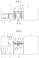
- Fig. 1 is a perspective view of a label printing system 100 when the continuous label tape roll has not been loaded yet.
- Fig. 2 is a top view as seen in a direction shown by arrow A of Fig. 1 .
- Fig. 3 is a front view as seen in a direction shown by arrow B. The label tape advances or is paid out in a direction shown by arrow C as shown in Fig. 1 .
- Fig. 4 is a perspective view of the label printing system 100 when the label tape 8 has been loaded.
- Fig. 5 is a top view as seen in a direction shown by arrow D of Fig. 4 .
- Fig. 6 is a side view as seen in a direction shown by arrow E in Fig. 4 .
- the label printing system 100 constitutes of a label printer 1 as a printing device, a pre-separation mechanism 19, and a post-separator 2.
- the label printing system 100 is configured to print on the label material releasably adhered to one side of the web by an adhesive ( Fig. 8C ).
- the roll of label tape 8 is rotatably supported on the label printer 1 via a supporting mechanism (not shown).
- the label tape 8 is paid out from the roll, and information is then printed on the label material.
- the label printer 1 pays out the printed label tape 8 through an exist 14 ( Figs. 1 and 4 ) to the pre-separation mechanism 19.
- the pre-separation mechanism 19 is located between the label printer 1 and the post-separator 2, and is fixed to the printer 1 and the post-separator 2 by means of an appropriate means (not shown).
- the pre-separation mechanism 19 detaches the residues or debris 11b from the label tape 8, leaving the labels 10 behind and allowing the labels 10 to remain attached to the web 9 until the label tape 8 arrives at the post-separator 2.
- a controller (not shown) sends command signals to the label printer 1 and the pre-separation mechanism 19 over cables, thereby driving the label printer 1 and the pre-separation mechanism 19 in synchronism.
- the pre-separation mechanism 19 drives its mechanical elements in accordance with the command signals, thereby properly transporting the label tape 8.
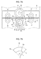
- Fig. 7A illustrates the pertinent portions of the pre-separation mechanism 19.
- Fig. 7B illustrates an annulus sector.
- An upper guide 24 and a lower guide 25 are substantially in the shape of a narrow plate, and extend straightly from the printer 1 to the post-separator 2.
- the upper and lower guides 24 and 25 are supported on a frame (not shown) with a predetermined space therebetween to define a label path 36 through which the label tape 8 advances.
- the label path 36 has an entrance that opens to the label printer 1 and an exit that opens to the post-separator 2.
- Each of the upper and lower guides 24 and 25 has an opening 24a or 25a through which the upper or lower feed roller 23 or 21 partially enters the path 36. The opening is located upstream of the upper and lower roller assemblies 30 and 33.
- a lower feed roller 21 and an upper feed roller 23 are disposed upstream of the upper and lower roller assemblies 30 and 33, and cooperate with each other to transport the label tape 8 sandwiched therebween toward the upper and lower roller assemblies 30 and 33.
- the lower feed roller 21 and the upper feed roller 23 partially enter the label path 36, and rotate each other to feed the label tape 8 to the upper and lower roller assemblies 30 and 33.
- the upper and lower feed rollers 23 and 21 each have a plurality of sub rollers as shown in Fig. 4 .
- the lower feed roller 21 and upper feed roller 23 constitute an upstream feed roller pair.
- An upper feed roller 22 and a lower feed roller 20 are disposed downstream of the upper and lower roller assemblies 30 and 33, and cooperate with each other to transport the label tape 8 sandwiched therebetween.
- the upper and lower feed rollers 22 and 20 each have a plurality of sub rollers as shown in Fig. 4 .
- the upper feed roller 22 and lower feed roller 20 constitute a downstream feed roller pair.
- Each of the upper and lower guides 24 and 25 has an opening 24b or 25b through which the upper or lower feed roller 23 or 21 partially enters the path 36, the opening 24b or 25b being located downstream of the upper and lower roller assemblies 30 and 33.
- the upper feed roller 22 and the lower feed roller 20 partially enter the label path 36 and rotate to feed the label tape 8.
- the upper feed roller 22 and the lower feed roller 20 hold the label tape 8 therebetween and rotate to further transport the label tape 8.
- the debris 11b will not adhere to the web again even though the upper feed roller 22 and the lower feed roller 20 hold the label tape 8 therebetween in a sandwiched relation.
- the upstream and downstream feed roller pairs are rotatably supported on a frame (not shown), and are driven in rotation by a drive source, e.g., a motor so that the upstream and downstream feed roller pairs cooperate with each other to transport the label tape 8 in accordance with the control commands from the controller.
- a drive source e.g., a motor
- An upper roller assembly 30 and a lower roller assembly 33 are disposed between the upstream and downstream feed roller pairs.
- a mark detector 26 is located under the lower guide 25 immediately upstream of the lower roller assembly 33.
- the upper roller assembly 30 is rotatably supported on a side frame (not shown) above the upper guide 24, and is mechanically coupled to the upstream feed roller pair and the downstream feed roller pair, so that the upper roller assembly 30 rotates in synchronism with the upstream and downstream feed roller pairs.
- the lower roller assembly 33 is rotatably supported on a side frame (not shown) under the lower guide 25, and is mechanically coupled to a drive mechanism different from that of the upper roller assembly 30, so that the lower roller assembly 33 rotates independently of the upper roller assembly 33.
- the upper roller assembly 30 and the lower roller assembly 33 have their rotational axes that lie in the same vertical plane.
- the mark detector 26 detects a black marker line 12, which is printed on a side of the web 9 opposite the labels 10 and indicates the position of the information printed on a corresponding label 10.
- the detection signal of the mark detector 26 is sent to the controller, and is used to controllably drive the pre-separation mechanism 19.
- the mark detector 26 may be disposed at any location as long as it is located upstream of the lower roller assembly 33, and downstream of the label printer 1.
- Figs. 8A and 8B illustrate the configuration of the label tape 8.
- Fig. 8C is a cross-sectional view taken along lines 8C-8C of Fig. 8A.
- Fig. 8A is a top view of the label tape 8.
- Fig. 8B is a side view of the label tape 8 when the label tape 8 has been partially paid out.
- the label tape 8 includes the web 9, labels 10, an adhesive coating 15, and the debris or residue 11.
- the label tape 8 is paid out in a direction shown by arrow H. As shown in Fig.
- the label material is half cut at boundaries 13, which surround each label 10, into the labels 10 and the debris 11 surrounding the labels 10, so that the labels 10 and the debris 11 still adhere to the web 9 but the labels 10 can be separated from the web 9 without difficulty at a later stage.
- the debris 11 can be peeled off from the web 9 while the labels 10 remain releasably adhered to the web 9.
- the mark line 12 is printed in a projected area, which is defined by projecting the label 10 onto a side of the web 9 opposite the label 10.
- the mark line 12 is in the vicinity of the trailing end of the label 10 with respect to the advance direction C of the label tape 8.
- the mark line 12 indicates a position where the information is printed on the label 10.
- the upper roller assembly 30 includes an upper roller shaft 31 rotatably supported on the side frame (not shown), and an elastic member 32 that covers the circumferential surface of the upper roller assembly 30.
- the elastic member 32 is formed of, for example, sponge.
- the lower roller assembly 33 includes a slit disc 28, a lower roller shaft 34, and four elastic members 35.
- the slit disc 28 has four slits 29 angularly equally spaced by 90°, the slits radially extending and having an identical shape.
- Each of the elastic members 35 has a cross-section in the shape of an annulus sector, and extends in a direction parallel to the lower roller shaft 34 ( Fig. 12 ), and a leading edge 35a and a trailing edge 35b with respect to the rotation of the lower roller assembly 33.
- Annulus sector is a shape ( Fig. 7B ) that has a center C, the opening angle ⁇ , and the radii 0 ⁇ r ⁇ R of the two circular arcs bounding it.
- the elastic members 35 are formed of, for example, a rubber material.
- the slits 29 are angularly equally spaced such that each slit is shifted by 90° in phase relative to the elastic member 35. In other words, each slit 29 is positioned angularly in the middle of adjacent elastic members 35.
- Fig. 7C is a perspective view of the slit disc 28 and a slit detector 27.
- Fig. 7D is a top view as seen in a direction shown by arrow F in Fig. 7C .
- the slit detector 27 is mounted on a frame (not shown), and includes a light source 27a and a light receiving section 27b.
- the slit detector 27 detects the slits 29 formed in the slit disc 28 when the slit disc 28 rotates.
- the detection signal of the slit detector 27 is sent to the controller over a cable. In response to the detection signal, the controller sends a command to stop the rotation of the lower roller assembly 33.
- Fig. 9 illustrates the positional relationship between the upper roller assembly 30 and the lower roller assembly 33 when the mark line 12 has not been detected by the mark detector 26 yet.
- the elastic member 35 of the lower roller assembly 33 has a hardness of A and the elastic member 32 of the upper roller assembly 30 has a hardness of B.
- the hardness are selected such that A is greater than B.
- Reference character D denotes an amount of dig by which the elastic member 35 is pushed into the elastic member 32 ( Fig. 9 ).
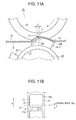
- the label 10 When the elastic member 35 digs strongly into the elastic member 32, the label 10 is pushed downward by the elastic member 32 while the label tape 8 is pushed upward by the leading edge 35a ( Fig. 11A ) of the circumferential surface of the elastic member 35. This causes the debris 11b to separate from the web 9, creating a small area S ( Fig. 11B ) between the debris 11b and the web 9. As a result, the debris 11 in the vicinity of the half cut line 13 is detached from the web 9.
- the circumferential dimension of the elastic member 35 should be at least as long as the width of the debris 11b.
- the post-separator 2 is located downstream of the pre-separation mechanism 19, and receives the label tape 8 whose debris 11 has been detached from the web 9 in the vicinity of the half cut line 13. The post-separator 2 separates the debris 11 from the web 9, leaving only the labels 10 adhered to the web 9.
- a guide roller 6 receives the label tape 8, and cooperates with a separator bar 7 to separate the debris 11 from the web 9.
- the guide roller 6 and the separator bar 7 are rotatably supported on a frame (not shown), and are configured to rotate freely.
- the debris 11 is then wound on a debris take-up spool 5.
- the web 9 on which the labels 10 remain attached is further advanced by the guide roller 6 and is wound on a web take-up spool 3, which is at a downstream end of the label advance direction.
- the web take-up spool 3 includes flanges 4 that are disposed at longitudinal end portions of the web take-up spool and guide the web 9 so that the web 9 is wound on the web stake-up pool 3 smoothly without misalignment.
- the web take-up spool 3 and the debris take-up spool 5 are driven in synchronism by a drive mechanism (bot shown).
- Figs. 7A-7D and 10-13 illustrate the operation of the pre-separation mechanism 19.
- the label printer 1 prints on the labels 10 of the label tape 8.
- the label tape 8 is then paid out through the exit 14 into the label path 36 defined by the upper guide 24 and the lower guide 25.
- the label tape 8 is transported by the upstream feed roller pair constituted of the upper and lower feed rollers 23 and 21, which rotate at a circumferential speed equivalent to the speed at which the label tape 8 is paid out.
- the label tape 8 enters the pre-separation mechanism 19 defined between the upper roller assembly 30 and the lower roller assembly 33.
- the upper roller assembly 30 is mechanically coupled to the upstream roller pair and the downstream roller pair.
- the upper roller assembly 30 rotates in synchronism with the upstream and downstream roller pairs.
- the lower roller assembly 33 is not mechanically coupled to the upstream and downstream roller pairs. Therefore, the lower roller assembly 33 in Fig. 9 is at rest.
- the four elastic members 35 slightly extend into the label path 36 or are completely out of the label path 36.
- the leading edge 35a of the elastic member 35-2 may or may not come in slight contact with the back surface of the web 9, so that the elastic member 35-2 will not interfere with the label tape 8 that advances through the label path 36.
- the mark detector 26 detects the black mark line 12 printed on the back side of the web 9, and sends the detection signal to the controller upon detection of the mark line 12.
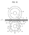
- the label tape 8 is further advanced a distance Y ( Fig. 10 ) for a short period of time t shortly after detection of the mark line 12.
- the controller drives the lower roller assembly 33 into rotation.
- the distance Y may be selected in accordance with the dimension L ( Fig. 8A ) of the label 10 extending in the advance direction of the label tape 8.
- the elastic member 35 comes into rolling pressure contact with the elastic member 32 of the upper roller assembly 30, and then digs into the elastic member 32.
- Figs. 12 and 13 illustrate the elastic members 32 and 35 when the elastic member 35 is pushed into the elastic member 32.
- Fig. 13 is an expanded view of a pertinent portion in the vicinity of the half cut line 13.
- the elastic member 35 and elastic member 32 are positioned relative to each other such that the half cut line 13 is a distance Z downstream of the leading edge 35a of the elastic member 35.
- the distance Z is a distance between the leading edge 35a and the half cut line 13.
- the debris 11 sits on the circumferential surface of the elastic member 35 while the label 10 and web 9 is pressed downward by the elastic member 32 at an area immediately downstream of the leading edge 35a of the elastic member 35 with respect to the advance direction of the label tape 8. Therefore, the debris 11 is separated from the web 9 at the half cut line 3. In this manner, portions 11b of the debris 11, which would otherwise make unpleasant sounds at the post-separator 2, are separated from the web 9 before the label tape 8 arrives at the post-separator 2.
- the upper and lower feed roller pairs continue to rotate so that the label tape 8 further advances as shown in Fig. 10 .
- the sensor 27 detects the slit 29 and sends the detection signal to the controller.
- the controller drives the drive mechanism to stop the rotation of the lower roller assembly 33, so that the lower roller assembly 33 comes to rest.
- the post-separator 2 receives the label tape 8 whose debris portions 11b have been detached, and removes only the entire debris 11 is from the web 9, leaving only the labels 10 on the web 9.
- Pre-separating the debris portions 11b which extends in a direction perpendicular to the direction in which the label tape 8 advances, provides smooth, quiet debris-separating operation at the post-separator 2, reducing unpleasant noise or sounds as well as preventing cutting off of the debris 11 in the middle of the removal operation of the debris 11 at the post separator 2.
- the present invention is not limited to the above-described embodiment, and may be modified in a variety of ways.
- the present invention may be applied to an apparatus configured to partially separate the leading edge portions of the labels on a label tape whose debris have been completely removed, so that the labels can be easily separated from the web of the label tape when the label is actually affixed to a product at a later stage.
- the four elastic members 35 have been described as having a cross section in the shape of an annulus sector, and the corner of the leading edge 35a of the elastic member 35 pushes up the label material in the vicinity of the half cut line 13.
- the number of the elastic members 35 may be increased as long as the corner of the leading edge 35a pushes up the label material in the vicinity of the half cut line 13.
- the sensor 27 has been described as detecting the slit 29 to stop the rotation of the lower roller assembly 33.
- the sensor 27 may be configured to detect other type of mark e.g., a line instead of the slit 29, as long as the mark properly indicates a position or timing to stop the lower roller assembly 33 and is detected reliably.
Landscapes
- Labeling Devices (AREA)
- Making Paper Articles (AREA)
- Winding Of Webs (AREA)
- Folding Of Thin Sheet-Like Materials, Special Discharging Devices, And Others (AREA)
Abstract
Description
- The present invention generally relates to a label separator and a label printing system.
- A composite label tape is comprised of a carrier web and label material releasably adhered by an adhesive to the carrier web. The label material includes labels and residues or debris that surround each label. Each label is removed from the carrier web, leaving the surrounding residues on the web, and is applied to a product surface.
Japanese Patent Publication No. 2006-181860 -
Fig. 14 illustrates the label tape when the residues are peeled. However, the apparatus suffers from the following drawbacks. The label tape includes aweb 9,half cut labels 10 and aresidue 11, which are attached on surface of theweb 9 by means of an adhesive. The residues include aportion 11a that extends in a direction parallel to a direction in which the label tape is paid out. When the residues begin to be peeled off from theweb 9, theportion 11a is first peeled substantially in the direction in which the label tape is paid out. Aportion 11b extends substantially in a direction perpendicular to theresidue 11a and begins to be peeled off at its longitudinal ends. When theportion 11b leaves theweb 9, unpleasant noise occurs. If theportion 11 is strongly adheres to theweb 9, theportion 11b may break at itsmiddle portion 11c. - The present invention was made to solve the drawbacks of conventional apparatus for removing residues of the label material of a half cut label tape.
- An object of the invention is to provide a label separator and a label printing system that do not make unpleasant noise.
- A debris separator pre-separates debris from a label tape (8), the label tape including a carrier web (9) and a label material, the label material being half cut into labels and debris (11) that surround all around individual labels (10). The label tape (8) is transported in a path (36). A first roller is disposed in the path (36), extends in a direction, and is covered with an elastic member. A second roller is disposed in the path (36), extends parallel to the first roller, and includes elastic members (35) angularly disposed on the second roller. The elastic members have circumferential surfaces. A controller controls the first and second rotatable bodies. The first and second rollers rotate with the label tape (8) sandwiched between their circumferential surfaces, the second circumferential surface digging into the first circumferential surface and the first circumferential surface pushing back the debris to detach the debris at least partially from the web.
- Further scope of applicability of the present invention will become apparent from the detailed description given hereinafter. However, it should be understood that the detailed description and specific examples, while indicating preferred embodiments of the invention, are given by way of illustration only, since various changes and modifications within the scope of the invention will become apparent to those skilled in the art from this detailed description.
- The present invention will become more fully understood from the detailed description given hereinbelow and the accompanying drawings which are given by way of illustration only, and wherein:
-
Fig. 1 is a perspective view of a label printing system according to the present invention when a continuous label tape roll has not been loaded yet; -
Fig. 2 is a top view as seen in a direction shown by arrow A inFig. 1 ; -
Fig. 3 is a front view as seen in a direction shown by arrow B inFig. 1 ; -
Fig. 4 is a perspective view of the label printing system when the label tape has been loaded; -
Fig. 5 is a top view as seen in a direction shown by arrow D inFig. 4 ; -
Fig. 6 is a side view as seen in a direction shown by arrow E inFig. 4 ; -
Fig. 7A illustrates the pertinent portions of a pre-separation mechanism; -
Fig. 7B illustrates an annulus sector; -
Fig. 7C is a perspective view of a slit disc and a slit detector; -
Fig. 7D is a top view as seen in a direction shown by arrow F inFig. 7C ; -
Fig. 8A is a top view of the label tape; -
Fig. 8B is a side view of the label tape when the label tape has been partially paid out; -
Fig. 8C is a cross-sectional view taken alonglines 8C-8C inFig. 8A ; -
Fig. 9 illustrates the positional relationship between an upper roller assembly and a lower roller assembly when a mark line on the label tape has not been detected by the mark detector yet; -
Fig. 10 illustrates the operation of the pre-separation mechanism; -
Figs. 11A, 11B , and12 illustrate elastic members of the lower roller assembly when the elastic member is pushed into the elastic member of the upper roller assembly; -
Fig. 13 is an expanded view of a pertinent portion in the vicinity of a half cut line printed on the label tape; and -
Fig. 14 illustrates a prior art label tape when residues are peeled from the label tape. - By way of preferred embodiments, the present invention will be described in detail with reference to the accompanying drawings.
- The label tape according to the invention includes a web, a label material, and an adhesive in a laminated structure, the label material being adhered to the web by the adhesive.
- The label material is a sheet, which is half cut to define labels and residues or peripheral portions, the residue surrounding each label. The residue includes
portions 11a that extend in directions parallel to the direction in which the label tape advances, andportions 11b that extend in directions perpendicular to theportions 11a. -
Fig. 1 is a perspective view of alabel printing system 100 when the continuous label tape roll has not been loaded yet.Fig. 2 is a top view as seen in a direction shown by arrow A ofFig. 1 .Fig. 3 is a front view as seen in a direction shown by arrow B. The label tape advances or is paid out in a direction shown by arrow C as shown inFig. 1 . -
Fig. 4 is a perspective view of thelabel printing system 100 when thelabel tape 8 has been loaded.Fig. 5 is a top view as seen in a direction shown by arrow D ofFig. 4 .Fig. 6 is a side view as seen in a direction shown by arrow E inFig. 4 . - Referring to
Figs. 1 and 2-6 , thelabel printing system 100 constitutes of alabel printer 1 as a printing device, apre-separation mechanism 19, and apost-separator 2. - The
label printing system 100 is configured to print on the label material releasably adhered to one side of the web by an adhesive (Fig. 8C ). - The roll of
label tape 8 is rotatably supported on thelabel printer 1 via a supporting mechanism (not shown). Thelabel tape 8 is paid out from the roll, and information is then printed on the label material. Thelabel printer 1 pays out the printedlabel tape 8 through an exist 14 (Figs. 1 and4 ) to thepre-separation mechanism 19. - The
pre-separation mechanism 19 is located between thelabel printer 1 and thepost-separator 2, and is fixed to theprinter 1 and the post-separator 2 by means of an appropriate means (not shown). Thepre-separation mechanism 19 detaches the residues ordebris 11b from thelabel tape 8, leaving thelabels 10 behind and allowing thelabels 10 to remain attached to theweb 9 until thelabel tape 8 arrives at thepost-separator 2. - A controller (not shown) sends command signals to the
label printer 1 and thepre-separation mechanism 19 over cables, thereby driving thelabel printer 1 and thepre-separation mechanism 19 in synchronism. Thepre-separation mechanism 19 drives its mechanical elements in accordance with the command signals, thereby properly transporting thelabel tape 8. -
Fig. 7A illustrates the pertinent portions of thepre-separation mechanism 19.Fig. 7B illustrates an annulus sector. Anupper guide 24 and alower guide 25 are substantially in the shape of a narrow plate, and extend straightly from theprinter 1 to thepost-separator 2. The upper andlower guides label path 36 through which thelabel tape 8 advances. Thelabel path 36 has an entrance that opens to thelabel printer 1 and an exit that opens to thepost-separator 2. Each of the upper andlower guides opening lower feed roller path 36. The opening is located upstream of the upper andlower roller assemblies - A
lower feed roller 21 and anupper feed roller 23 are disposed upstream of the upper andlower roller assemblies label tape 8 sandwiched therebween toward the upper andlower roller assemblies lower feed roller 21 and theupper feed roller 23 partially enter thelabel path 36, and rotate each other to feed thelabel tape 8 to the upper andlower roller assemblies lower feed rollers Fig. 4 . Thelower feed roller 21 andupper feed roller 23 constitute an upstream feed roller pair. Anupper feed roller 22 and alower feed roller 20 are disposed downstream of the upper andlower roller assemblies label tape 8 sandwiched therebetween. The upper andlower feed rollers Fig. 4 . Theupper feed roller 22 andlower feed roller 20 constitute a downstream feed roller pair. Each of the upper andlower guides opening lower feed roller path 36, theopening lower roller assemblies upper feed roller 22 and thelower feed roller 20 partially enter thelabel path 36 and rotate to feed thelabel tape 8. When thelabel tape 8 passes through the gap between the upper andlower feed rollers debris 11b has been peeled off theweb 9, theupper feed roller 22 and thelower feed roller 20 hold thelabel tape 8 therebetween and rotate to further transport thelabel tape 8. Once thedebris 11b has been peeled off theweb 9, thedebris 11b will not adhere to the web again even though theupper feed roller 22 and thelower feed roller 20 hold thelabel tape 8 therebetween in a sandwiched relation. - The upstream and downstream feed roller pairs are rotatably supported on a frame (not shown), and are driven in rotation by a drive source, e.g., a motor so that the upstream and downstream feed roller pairs cooperate with each other to transport the
label tape 8 in accordance with the control commands from the controller. - An
upper roller assembly 30 and alower roller assembly 33 are disposed between the upstream and downstream feed roller pairs. Amark detector 26 is located under thelower guide 25 immediately upstream of thelower roller assembly 33. - The
upper roller assembly 30 is rotatably supported on a side frame (not shown) above theupper guide 24, and is mechanically coupled to the upstream feed roller pair and the downstream feed roller pair, so that theupper roller assembly 30 rotates in synchronism with the upstream and downstream feed roller pairs. - The
lower roller assembly 33 is rotatably supported on a side frame (not shown) under thelower guide 25, and is mechanically coupled to a drive mechanism different from that of theupper roller assembly 30, so that thelower roller assembly 33 rotates independently of theupper roller assembly 33. Theupper roller assembly 30 and thelower roller assembly 33 have their rotational axes that lie in the same vertical plane. - The
mark detector 26 detects ablack marker line 12, which is printed on a side of theweb 9 opposite thelabels 10 and indicates the position of the information printed on acorresponding label 10. The detection signal of themark detector 26 is sent to the controller, and is used to controllably drive thepre-separation mechanism 19. Themark detector 26 may be disposed at any location as long as it is located upstream of thelower roller assembly 33, and downstream of thelabel printer 1. -
Figs. 8A and 8B illustrate the configuration of thelabel tape 8.Fig. 8C is a cross-sectional view taken alonglines 8C-8C ofFig. 8A. Fig. 8A is a top view of thelabel tape 8.Fig. 8B is a side view of thelabel tape 8 when thelabel tape 8 has been partially paid out. Referring toFig. 8C , thelabel tape 8 includes theweb 9, labels 10, anadhesive coating 15, and the debris orresidue 11. Thelabel tape 8 is paid out in a direction shown by arrow H. As shown inFig. 8C , the label material is half cut atboundaries 13, which surround eachlabel 10, into thelabels 10 and thedebris 11 surrounding thelabels 10, so that thelabels 10 and thedebris 11 still adhere to theweb 9 but thelabels 10 can be separated from theweb 9 without difficulty at a later stage. Thus, thedebris 11 can be peeled off from theweb 9 while thelabels 10 remain releasably adhered to theweb 9. - The
mark line 12 is printed in a projected area, which is defined by projecting thelabel 10 onto a side of theweb 9 opposite thelabel 10. Themark line 12 is in the vicinity of the trailing end of thelabel 10 with respect to the advance direction C of thelabel tape 8. Themark line 12 indicates a position where the information is printed on thelabel 10. - Referring to
Fig. 7A , theupper roller assembly 30 includes anupper roller shaft 31 rotatably supported on the side frame (not shown), and anelastic member 32 that covers the circumferential surface of theupper roller assembly 30. Theelastic member 32 is formed of, for example, sponge. - The
lower roller assembly 33 includes aslit disc 28, alower roller shaft 34, and fourelastic members 35. Theslit disc 28 has fourslits 29 angularly equally spaced by 90°, the slits radially extending and having an identical shape. Each of theelastic members 35 has a cross-section in the shape of an annulus sector, and extends in a direction parallel to the lower roller shaft 34 (Fig. 12 ), and aleading edge 35a and a trailingedge 35b with respect to the rotation of thelower roller assembly 33. Annulus sector is a shape (Fig. 7B ) that has a center C, the opening angle θ, and the radii 0<r<R of the two circular arcs bounding it. Theelastic members 35 are formed of, for example, a rubber material. - The
slits 29 are angularly equally spaced such that each slit is shifted by 90° in phase relative to theelastic member 35. In other words, each slit 29 is positioned angularly in the middle of adjacentelastic members 35. -
Fig. 7C is a perspective view of theslit disc 28 and aslit detector 27.Fig. 7D is a top view as seen in a direction shown by arrow F inFig. 7C . Theslit detector 27 is mounted on a frame (not shown), and includes alight source 27a and alight receiving section 27b. Theslit detector 27 detects theslits 29 formed in theslit disc 28 when theslit disc 28 rotates. The detection signal of theslit detector 27 is sent to the controller over a cable. In response to the detection signal, the controller sends a command to stop the rotation of thelower roller assembly 33. -
Fig. 9 illustrates the positional relationship between theupper roller assembly 30 and thelower roller assembly 33 when themark line 12 has not been detected by themark detector 26 yet. - The
elastic member 35 of thelower roller assembly 33 has a hardness of A and theelastic member 32 of theupper roller assembly 30 has a hardness of B. The hardness are selected such that A is greater than B. - When the upper and
lower roller assemblies elastic member 35 is brought into contact with theelastic member 32 of theupper roller assembly 30, so that theelastic member 35 is pushed or dug into theelastic member 32. Reference character D denotes an amount of dig by which theelastic member 35 is pushed into the elastic member 32 (Fig. 9 ). - When the
elastic member 35 digs strongly into theelastic member 32, thelabel 10 is pushed downward by theelastic member 32 while thelabel tape 8 is pushed upward by theleading edge 35a (Fig. 11A ) of the circumferential surface of theelastic member 35. This causes thedebris 11b to separate from theweb 9, creating a small area S (Fig. 11B ) between thedebris 11b and theweb 9. As a result, thedebris 11 in the vicinity of thehalf cut line 13 is detached from theweb 9. The circumferential dimension of theelastic member 35 should be at least as long as the width of thedebris 11b. - The
post-separator 2 is located downstream of thepre-separation mechanism 19, and receives thelabel tape 8 whosedebris 11 has been detached from theweb 9 in the vicinity of thehalf cut line 13. Thepost-separator 2 separates thedebris 11 from theweb 9, leaving only thelabels 10 adhered to theweb 9. - Referring to
Figs. 2 and6 , aguide roller 6 receives thelabel tape 8, and cooperates with aseparator bar 7 to separate thedebris 11 from theweb 9. Theguide roller 6 and theseparator bar 7 are rotatably supported on a frame (not shown), and are configured to rotate freely. Thedebris 11 is then wound on a debris take-upspool 5. Theweb 9 on which thelabels 10 remain attached is further advanced by theguide roller 6 and is wound on a web take-upspool 3, which is at a downstream end of the label advance direction. The web take-upspool 3 includesflanges 4 that are disposed at longitudinal end portions of the web take-up spool and guide theweb 9 so that theweb 9 is wound on the web stake-uppool 3 smoothly without misalignment. The web take-upspool 3 and the debris take-upspool 5 are driven in synchronism by a drive mechanism (bot shown). - The operation of the
label printing system 100 will be described in detail with reference toFigs. 10-13 . -
Figs. 7A-7D and 10-13 illustrate the operation of thepre-separation mechanism 19. - The
label printer 1 prints on thelabels 10 of thelabel tape 8. Thelabel tape 8 is then paid out through theexit 14 into thelabel path 36 defined by theupper guide 24 and thelower guide 25. - The
label tape 8 is transported by the upstream feed roller pair constituted of the upper andlower feed rollers label tape 8 is paid out. Thelabel tape 8 enters thepre-separation mechanism 19 defined between theupper roller assembly 30 and thelower roller assembly 33. - The
upper roller assembly 30 is mechanically coupled to the upstream roller pair and the downstream roller pair. Thus, theupper roller assembly 30 rotates in synchronism with the upstream and downstream roller pairs. On the other hand, thelower roller assembly 33 is not mechanically coupled to the upstream and downstream roller pairs. Therefore, thelower roller assembly 33 inFig. 9 is at rest. - When the
lower roller assembly 33 is at rest, the fourelastic members 35 slightly extend into thelabel path 36 or are completely out of thelabel path 36. At this moment, theleading edge 35a of the elastic member 35-2 may or may not come in slight contact with the back surface of theweb 9, so that the elastic member 35-2 will not interfere with thelabel tape 8 that advances through thelabel path 36. - Referring to
Fig. 9 , themark detector 26 detects theblack mark line 12 printed on the back side of theweb 9, and sends the detection signal to the controller upon detection of themark line 12. - The
label tape 8 is further advanced a distance Y (Fig. 10 ) for a short period of time t shortly after detection of themark line 12. At the end of the short period of time t , the controller drives thelower roller assembly 33 into rotation. - It is desirable that the
lower roller assembly 33 starts to rotate when themark line 12 arrives substantially at theleading edge 35a of the elastic member 35-2. The distance Y (Fig. 10 ) may be selected in accordance with the dimension L (Fig. 8A ) of thelabel 10 extending in the advance direction of thelabel tape 8. - As shown in
Fig. 11A and 11B , theelastic member 35 comes into rolling pressure contact with theelastic member 32 of theupper roller assembly 30, and then digs into theelastic member 32. -
Figs. 12 and 13 illustrate theelastic members elastic member 35 is pushed into theelastic member 32.Fig. 13 is an expanded view of a pertinent portion in the vicinity of thehalf cut line 13. - Referring to
Fig. 13 , when theelastic member 35 is pushed into theelastic member 32, theelastic member 35 andelastic member 32 are positioned relative to each other such that thehalf cut line 13 is a distance Z downstream of theleading edge 35a of theelastic member 35. Referring back toFigs. 11A and 11B , the distance Z is a distance between theleading edge 35a and thehalf cut line 13. - When the
label tape 8 is sandwiched between theelastic member 32 and theelastic member 35, thedebris 11 sits on the circumferential surface of theelastic member 35 while thelabel 10 andweb 9 is pressed downward by theelastic member 32 at an area immediately downstream of theleading edge 35a of theelastic member 35 with respect to the advance direction of thelabel tape 8. Therefore, thedebris 11 is separated from theweb 9 at thehalf cut line 3. In this manner,portions 11b of thedebris 11, which would otherwise make unpleasant sounds at the post-separator 2, are separated from theweb 9 before thelabel tape 8 arrives at thepost-separator 2. - The upper and lower feed roller pairs continue to rotate so that the
label tape 8 further advances as shown inFig. 10 . When theslit 29 passes thesensor 27, thesensor 27 detects theslit 29 and sends the detection signal to the controller. In response to the detection signal, the controller drives the drive mechanism to stop the rotation of thelower roller assembly 33, so that thelower roller assembly 33 comes to rest. - As described above, the operation of the
pre-separation mechanism 19 illustrated inFigs. 9 ,11A and 11B is repeated for eachdebris portion 11b, so that thedebris portions 11b are detached from theweb 9 beforelabel tape 8 arrives at thepost-separator 2. - The
post-separator 2 receives thelabel tape 8 whosedebris portions 11b have been detached, and removes only theentire debris 11 is from theweb 9, leaving only thelabels 10 on theweb 9. - Pre-separating the
debris portions 11b, which extends in a direction perpendicular to the direction in which thelabel tape 8 advances, provides smooth, quiet debris-separating operation at the post-separator 2, reducing unpleasant noise or sounds as well as preventing cutting off of thedebris 11 in the middle of the removal operation of thedebris 11 at thepost separator 2. - The present invention is not limited to the above-described embodiment, and may be modified in a variety of ways. For example, the present invention may be applied to an apparatus configured to partially separate the leading edge portions of the labels on a label tape whose debris have been completely removed, so that the labels can be easily separated from the web of the label tape when the label is actually affixed to a product at a later stage.
- The four
elastic members 35 have been described as having a cross section in the shape of an annulus sector, and the corner of theleading edge 35a of theelastic member 35 pushes up the label material in the vicinity of thehalf cut line 13. Alternatively, the number of theelastic members 35 may be increased as long as the corner of theleading edge 35a pushes up the label material in the vicinity of thehalf cut line 13. - The
sensor 27 has been described as detecting theslit 29 to stop the rotation of thelower roller assembly 33. Alternatively, thesensor 27 may be configured to detect other type of mark e.g., a line instead of theslit 29, as long as the mark properly indicates a position or timing to stop thelower roller assembly 33 and is detected reliably. - The invention being thus described, it will be obvious that the same may be varied in many ways. Such variations are not to be regarded as a departure from the scope of the invention, and all such modifications as would be obvious to one skilled in the art are intended to be included within the scope of the following claims.
Claims (7)
- A debris separator for pre-separating debris from a label tape (8), the label tape including a carrier web (9) and a label material releasably adhered to the carrier web by an adhesive, the label material being half cut into labels and debris (11) that surround all around individual label (10), the separator comprising:a transport path (36) through which the label tape (8) is transported;a first rotatable body disposed in the transport path (36) and extending in a first longitudinal direction thereof;a first elastic member (32) that covers the first rotatable body, the first elastic member including a first circumferential surface rotatable in contact with a surface of the label material;a second rotatable body disposed in the transport path (36) and extending in a second longitudinal direction thereof parallel to the first longitudinal direction;a plurality of second elastic members (35) angularly disposed on the second rotatable body, each of the second elastic members including a second circumferential surface rotatable in contact with a side of the carrier web (9) opposite the labels (10); anda controller configured to control the first rotatable body and the second rotatable body;wherein, when in use, the first and second rotatable bodies rotate with the label tape (8) sandwiched between the first circumferential surface and the second circumferential surface, the second circumferential surface digging into the first circumferential surface, so that the first circumferential surface pushes back the debris to detach the debris at least partially from the web.
- The debris separator according to claim 1, wherein the second circumferential surface is a circumferential surface of an annulus sector, wherein the debris separator further comprises:a plurality of angularly spaced first marks; anda first detector (27) configured to detect the first marks and output a first detection signal.
- The debris separator according to claim 1 further comprising:a second detector (26) configured to detect a second mark on the label tape (8) and output a second detection signal;wherein the controller drives the second rotatable body into rotation when the label tape (8) has advanced a distance (Y) after the second detector outputs the second detection signal.
- The debris separator according to claim 2 or claim 3, wherein the controller causes the second rotatable body to stop rotation thereof in response to the first detection signal.
- The debris separator according to any one of claims 1 to 4, wherein the second elastic member (35) has a higher hardness than the first elastic member (32).
- The debris separator according to claim 2, wherein each of the first marks is located between adjacent ones of the second elastic members.
- The debris separator according to claim 6, wherein the plurality of second elastic members include four second elastic members angularly equally spaced, and four first marks are shifted by 45 degrees in phase relative to the four second elastic members.
Applications Claiming Priority (1)
| Application Number | Priority Date | Filing Date | Title |
|---|---|---|---|
| JP2015065012A JP2016182777A (en) | 2015-03-26 | 2015-03-26 | Waste peeling apparatus and label printing system |
Publications (1)
| Publication Number | Publication Date |
|---|---|
| EP3072822A1 true EP3072822A1 (en) | 2016-09-28 |
Family
ID=55024794
Family Applications (1)
| Application Number | Title | Priority Date | Filing Date |
|---|---|---|---|
| EP15200092.3A Withdrawn EP3072822A1 (en) | 2015-03-26 | 2015-12-15 | Debris separator for label tape |
Country Status (4)
| Country | Link |
|---|---|
| US (1) | US20160279924A1 (en) |
| EP (1) | EP3072822A1 (en) |
| JP (1) | JP2016182777A (en) |
| CN (1) | CN106004079A (en) |
Cited By (1)
| Publication number | Priority date | Publication date | Assignee | Title |
|---|---|---|---|---|
| CN110002070A (en) * | 2019-04-30 | 2019-07-12 | 深圳格兰达智能装备股份有限公司 | A kind of full-automatic labeling device of electronic component of view-based access control model correction |
Families Citing this family (4)
| Publication number | Priority date | Publication date | Assignee | Title |
|---|---|---|---|---|
| JP2018147058A (en) * | 2017-03-01 | 2018-09-20 | ブラザー工業株式会社 | Label creation processing program, label creation processing method, and label printer |
| CN108501503B (en) * | 2018-05-25 | 2024-04-23 | 安徽佳通乘用子午线轮胎有限公司 | Online stripping device for film and PE paper |
| EP4124449B1 (en) * | 2021-07-28 | 2025-10-15 | S+P Samson GmbH | Label, labelstrip and method for manufacturing labels |
| NL2035620B1 (en) * | 2023-08-17 | 2025-02-28 | Vmi Holland Bv | Peeler, let-off station and method for peeling off a liner and a stock material from each other |
Citations (3)
| Publication number | Priority date | Publication date | Assignee | Title |
|---|---|---|---|---|
| US5824184A (en) * | 1994-08-10 | 1998-10-20 | Seiko Epson Corporation | Structure for removing a peel-off backing from an adhesive tape |
| JP2006181860A (en) | 2004-12-27 | 2006-07-13 | Sato Corp | Waste peeling device |
| EP2703152A1 (en) * | 2011-04-28 | 2014-03-05 | Sato Holdings Kabushiki Kaisha | Label-producing method and label |
Family Cites Families (18)
| Publication number | Priority date | Publication date | Assignee | Title |
|---|---|---|---|---|
| US2304787A (en) * | 1939-04-12 | 1942-12-15 | Avery Ray Stanton | Nondrying adhesive label and method and apparatus for making same |
| US4165251A (en) * | 1976-11-22 | 1979-08-21 | Fuji Photo Film Co., Ltd. | Stripping and developing device |
| US4282056A (en) * | 1979-01-04 | 1981-08-04 | Tokujiro Okui | Both-surface adhesive tape producing apparatus |
| US4405401A (en) * | 1981-07-15 | 1983-09-20 | Stahl Ted A | Thermoplastic labeling and method of making same |
| JPH0688237B2 (en) * | 1988-12-21 | 1994-11-09 | 新王子製紙株式会社 | Control device for stopping the sheet cutter |
| JP2555494Y2 (en) * | 1992-01-31 | 1997-11-26 | 株式会社丸善 | Embossing equipment such as paper towels |
| JP3156419B2 (en) * | 1993-02-15 | 2001-04-16 | 松下電器産業株式会社 | Method of removing separator for protecting anisotropic conductive film |
| US5466321A (en) * | 1993-12-17 | 1995-11-14 | Sanki Machinery Co., Ltd. | Method of and apparatus for superposing strip members |
| JPH0872837A (en) * | 1994-09-06 | 1996-03-19 | King Jim Co Ltd | Edge peeling device for sheet with release paper |
| JP2639900B2 (en) * | 1995-03-07 | 1997-08-13 | エーアールシー株式会社 | Label continuum and method for producing the same |
| US6786266B2 (en) * | 2000-05-26 | 2004-09-07 | K. K. Mashintex | Waste peeling apparatus |
| US6592693B1 (en) * | 2000-08-11 | 2003-07-15 | Greydon Wesley Nedblake | Method and apparatus for laser cutting of adhesive-bearing webs separate from liner webs |
| US6547913B1 (en) * | 2000-09-07 | 2003-04-15 | Airtrim, Inc. | Apparatus for conveying an adhesively coated scrap lattice web |
| JP3990264B2 (en) * | 2002-12-10 | 2007-10-10 | 富士フイルム株式会社 | Protective sheet peeling device |
| CN102149521A (en) * | 2008-07-14 | 2011-08-10 | 艾利丹尼森公司 | Apparatus and method for cutting glued labels |
| JP5039805B2 (en) * | 2010-03-05 | 2012-10-03 | 株式会社沖データ | Label printer |
| JP5801811B2 (en) * | 2010-08-10 | 2015-10-28 | リンテック株式会社 | Sheet peeling apparatus and peeling method, sheet sticking apparatus and sticking method |
| DE102012019372B4 (en) * | 2011-10-26 | 2025-03-13 | Masterwork Machinery Co., Ltd. | Method for embossing products with a rotary embossing device |
-
2015
- 2015-03-26 JP JP2015065012A patent/JP2016182777A/en active Pending
- 2015-12-15 EP EP15200092.3A patent/EP3072822A1/en not_active Withdrawn
- 2015-12-17 US US14/972,203 patent/US20160279924A1/en not_active Abandoned
- 2015-12-18 CN CN201510949736.8A patent/CN106004079A/en active Pending
Patent Citations (3)
| Publication number | Priority date | Publication date | Assignee | Title |
|---|---|---|---|---|
| US5824184A (en) * | 1994-08-10 | 1998-10-20 | Seiko Epson Corporation | Structure for removing a peel-off backing from an adhesive tape |
| JP2006181860A (en) | 2004-12-27 | 2006-07-13 | Sato Corp | Waste peeling device |
| EP2703152A1 (en) * | 2011-04-28 | 2014-03-05 | Sato Holdings Kabushiki Kaisha | Label-producing method and label |
Cited By (1)
| Publication number | Priority date | Publication date | Assignee | Title |
|---|---|---|---|---|
| CN110002070A (en) * | 2019-04-30 | 2019-07-12 | 深圳格兰达智能装备股份有限公司 | A kind of full-automatic labeling device of electronic component of view-based access control model correction |
Also Published As
| Publication number | Publication date |
|---|---|
| JP2016182777A (en) | 2016-10-20 |
| US20160279924A1 (en) | 2016-09-29 |
| CN106004079A (en) | 2016-10-12 |
Similar Documents
| Publication | Publication Date | Title |
|---|---|---|
| US20160279924A1 (en) | Label separator and label printing system | |
| EP2634104B1 (en) | Labeling device | |
| JP4938927B2 (en) | Adhesive sheet cutting device | |
| US6146728A (en) | Binder strips on a carrier film, and method and apparatus for applying binder strips onto sheet goods | |
| US10766658B2 (en) | Label peeling device | |
| US5947408A (en) | Recording device using continuous paper and method of feeding continuous paper | |
| US5520776A (en) | Method and apparatus for delaminating a laminate | |
| JP4968835B2 (en) | Multiple sheet production equipment | |
| CN108724981B (en) | Self-Peeling Media Module | |
| JP2015071476A (en) | Printer | |
| JPH11221948A (en) | Mechanism preventing linerless label from being caught and printer provided there with | |
| JP2005213026A (en) | Label printer and label peeling method | |
| KR101759404B1 (en) | Printing paper cutting device and printing device | |
| JP3349171B2 (en) | Laminated sheet cutter construction | |
| JP3753460B2 (en) | Print cutting device for label without mount | |
| US20040163751A1 (en) | Method of and apparatus for affixing backing to plates | |
| JP2009234595A (en) | Label guiding device for automatic labeling machine | |
| CN206306616U (en) | Hole plate print device | |
| JP3408055B2 (en) | Fixing device | |
| EP3162580B1 (en) | Printer device | |
| JPH0919888A (en) | Paper sheet cutting device | |
| US6499733B1 (en) | Method and apparatus for feeding sheet material into a printer or copier | |
| EP1312570A2 (en) | Apparatus and method for affixing cards to a web | |
| US6475322B1 (en) | Sheet lamination with transverse sheet bias to eliminate trailing edge coating debris | |
| JP2000281029A (en) | Print cutting device for label without mount |
Legal Events
| Date | Code | Title | Description |
|---|---|---|---|
| PUAI | Public reference made under article 153(3) epc to a published international application that has entered the european phase |
Free format text: ORIGINAL CODE: 0009012 |
|
| AK | Designated contracting states |
Kind code of ref document: A1 Designated state(s): AL AT BE BG CH CY CZ DE DK EE ES FI FR GB GR HR HU IE IS IT LI LT LU LV MC MK MT NL NO PL PT RO RS SE SI SK SM TR |
|
| AX | Request for extension of the european patent |
Extension state: BA ME |
|
| STAA | Information on the status of an ep patent application or granted ep patent |
Free format text: STATUS: REQUEST FOR EXAMINATION WAS MADE |
|
| 17P | Request for examination filed |
Effective date: 20170303 |
|
| RBV | Designated contracting states (corrected) |
Designated state(s): AL AT BE BG CH CY CZ DE DK EE ES FI FR GB GR HR HU IE IS IT LI LT LU LV MC MK MT NL NO PL PT RO RS SE SI SK SM TR |
|
| GRAP | Despatch of communication of intention to grant a patent |
Free format text: ORIGINAL CODE: EPIDOSNIGR1 |
|
| STAA | Information on the status of an ep patent application or granted ep patent |
Free format text: STATUS: GRANT OF PATENT IS INTENDED |
|
| INTG | Intention to grant announced |
Effective date: 20170418 |
|
| STAA | Information on the status of an ep patent application or granted ep patent |
Free format text: STATUS: THE APPLICATION IS DEEMED TO BE WITHDRAWN |
|
| 18D | Application deemed to be withdrawn |
Effective date: 20170829 |