EP3072746A1 - Exterior component for a vehicle - Google Patents
Exterior component for a vehicle Download PDFInfo
- Publication number
- EP3072746A1 EP3072746A1 EP16159184.7A EP16159184A EP3072746A1 EP 3072746 A1 EP3072746 A1 EP 3072746A1 EP 16159184 A EP16159184 A EP 16159184A EP 3072746 A1 EP3072746 A1 EP 3072746A1
- Authority
- EP
- European Patent Office
- Prior art keywords
- recessed portion
- exterior component
- annular
- joint portion
- vehicle
- Prior art date
- Legal status (The legal status is an assumption and is not a legal conclusion. Google has not performed a legal analysis and makes no representation as to the accuracy of the status listed.)
- Granted
Links
- 239000000853 adhesive Substances 0.000 claims abstract description 38
- 230000001070 adhesive effect Effects 0.000 claims abstract description 38
- 239000007788 liquid Substances 0.000 claims abstract description 8
- 238000006073 displacement reaction Methods 0.000 claims description 11
- 238000009434 installation Methods 0.000 claims description 9
- 239000002390 adhesive tape Substances 0.000 claims description 7
- 238000011417 postcuring Methods 0.000 claims description 4
- 230000002093 peripheral effect Effects 0.000 claims description 3
- XLYOFNOQVPJJNP-UHFFFAOYSA-N water Substances O XLYOFNOQVPJJNP-UHFFFAOYSA-N 0.000 description 10
- 239000011347 resin Substances 0.000 description 6
- 229920005989 resin Polymers 0.000 description 6
- 239000000463 material Substances 0.000 description 5
- 230000008901 benefit Effects 0.000 description 3
- 230000006872 improvement Effects 0.000 description 3
- 230000035515 penetration Effects 0.000 description 3
- 239000000758 substrate Substances 0.000 description 3
- 230000035945 sensitivity Effects 0.000 description 2
- 239000011248 coating agent Substances 0.000 description 1
- 238000000576 coating method Methods 0.000 description 1
- 230000000694 effects Effects 0.000 description 1
- 239000013013 elastic material Substances 0.000 description 1
- 235000012907 honey Nutrition 0.000 description 1
- 230000009191 jumping Effects 0.000 description 1
- 238000000034 method Methods 0.000 description 1
- 230000009467 reduction Effects 0.000 description 1
- 230000007480 spreading Effects 0.000 description 1
- 238000005406 washing Methods 0.000 description 1
- 238000003466 welding Methods 0.000 description 1
Images

Classifications
-
- B—PERFORMING OPERATIONS; TRANSPORTING
- B60—VEHICLES IN GENERAL
- B60R—VEHICLES, VEHICLE FITTINGS, OR VEHICLE PARTS, NOT OTHERWISE PROVIDED FOR
- B60R13/00—Elements for body-finishing, identifying, or decorating; Arrangements or adaptations for advertising purposes
- B60R13/06—Sealing strips
-
- B—PERFORMING OPERATIONS; TRANSPORTING
- B60—VEHICLES IN GENERAL
- B60R—VEHICLES, VEHICLE FITTINGS, OR VEHICLE PARTS, NOT OTHERWISE PROVIDED FOR
- B60R13/00—Elements for body-finishing, identifying, or decorating; Arrangements or adaptations for advertising purposes
- B60R13/005—Manufacturers' emblems, name plates, bonnet ornaments, mascots or the like; Mounting means therefor
Definitions
- This disclosure relates to an exterior component for a vehicle.
- a method of using an O-ring made of an elastic material such as rubber is generally used (for example, see JP2009-282068A (Reference 1)). That is, it is possible to fill a gap of the joint portion by squeezing the O-ring by using a fastening force between the two members. Thus, it is possible to secure waterproofness.
- An aspect of this disclosure is directed to an exterior component for a vehicle preferably including a first member that has a design surface disposed on a vehicle surface; and a second member that forms a housing space which is sealed between the first member and the second member in a liquid tight manner by being joined to the first member on a rear side of the design surface, in which a joint portion between the first member and the second member is configured of an annular recessed portion that is provided on one side of the first member and the second member, an annular protrusion portion that is provided on the other side of the first member and the second member, and elastic adhesive with which an inside of the annular recessed portion is filled thereby fixing the annular protrusion portion inserted into the inside of the annular recessed portion over the entire peripheries of the annular protrusion portion and the annular recessed portion.
- the first member and the second member are evenly joined over the entire peripheries of the annular protrusion portion and the annular recessed portion.
- a labyrinth structure in which the annular recessed portion and the annular protrusion portion inserted into the inside of the annular recessed portion are entangled with each other, is formed.
- the applied elastic adhesive is held on the inside of the annular recessed portion by the labyrinth structure.
- dimensions of an external shape are enlarged by increasing fastening portions so as to reduce squeeze unevenness of an O-ring.
- the first member includes a peripheral wall portion surrounding an outside of the joint portion on the rear side of the design surface.
- the joint portion is unlikely to be wet by water.
- the second member is disposed on an inside of an installation recessed portion formed on the vehicle surface, and the first member has a flange portion whose leading end faces an inner wall surface of the installation recessed portion by being continuous to the design surface and extending further to an outer side than the joint portion.
- the exterior component for a vehicle described above further includes a holding portion of a housed body further on an inner side than the joint portion.
- the joint portion between the first member and the second member which is formed of the annular recessed portion, the annular protrusion portion, and the elastic adhesive, has the structure to allow penetration of water to the outside of the elastic adhesive applied to the inside of the annular recessed portion.
- the housed body held on the inside of the housing space does not overlap with the joint portion when viewed from the design surface side.
- the elastic adhesive has elasticity capable of allowing relative displacement based on a difference in thermal expansion coefficient between the first member and the second member, even in a post-curing state to fix the annular protrusion portion inserted into the inside of the annular recessed portion.
- the joint portion has a ring shape.
- the exterior component for a vehicle described above further includes a second joint portion joining the first member and the second member.
- the second joint portion joins the first member and the second member within the housing space on an inner side than the annular recessed portion.
- the second joint portion is a double-sided adhesive tape.
- the emblem switch 1 of the embodiment is fixed to the inside of the installation recessed portion 15 using the screw stop portion 28 formed in the second member 12.
- the second member 12 is disposed on the inside of the installation recessed portion 15 and then the surface portion 11 a of the first member 11 configuring the design surface 2s is configured to be disposed in a position in which the surface portion 11a slightly protrudes from the vehicle surface S.
Landscapes
- Engineering & Computer Science (AREA)
- Mechanical Engineering (AREA)
- Casings For Electric Apparatus (AREA)
- Vehicle Interior And Exterior Ornaments, Soundproofing, And Insulation (AREA)
- Vehicle Waterproofing, Decoration, And Sanitation Devices (AREA)
- Push-Button Switches (AREA)
Abstract
Description
- This disclosure relates to an exterior component for a vehicle.
- In the related art, as a waterproof structure to seal a joint portion between two members in a liquid tight manner, a method of using an O-ring made of an elastic material such as rubber is generally used (for example, see
JP2009-282068A - However, if such a waterproof structure is applied to, for example, an exterior component of a vehicle such as an emblem part, squeeze unevenness of the O-ring becomes a problem. That is, a squeeze amount of the O-ring is reduced in a position separated from a fastening portion by a bolt, a screw, and the like. Then, in a case of the exterior component disposed on a vehicle surface, penetration of water may be allowed from a portion in which the squeeze amount of the O-ring is small by a water pressure at the time of high-pressure washing. Thus, in this respect, there is still room for improvement.
- Thus, a need exists for an exterior component for a vehicle that is further excellent in waterproofness.
- An aspect of this disclosure is directed to an exterior component for a vehicle preferably including a first member that has a design surface disposed on a vehicle surface; and a second member that forms a housing space which is sealed between the first member and the second member in a liquid tight manner by being joined to the first member on a rear side of the design surface, in which a joint portion between the first member and the second member is configured of an annular recessed portion that is provided on one side of the first member and the second member, an annular protrusion portion that is provided on the other side of the first member and the second member, and elastic adhesive with which an inside of the annular recessed portion is filled thereby fixing the annular protrusion portion inserted into the inside of the annular recessed portion over the entire peripheries of the annular protrusion portion and the annular recessed portion.
- According to the configuration described above, the first member and the second member are evenly joined over the entire peripheries of the annular protrusion portion and the annular recessed portion. In addition, a labyrinth structure, in which the annular recessed portion and the annular protrusion portion inserted into the inside of the annular recessed portion are entangled with each other, is formed. Furthermore, the applied elastic adhesive is held on the inside of the annular recessed portion by the labyrinth structure. Thus, it is possible to secure high waterproofness. In addition, in a case of the related art, dimensions of an external shape are enlarged by increasing fastening portions so as to reduce squeeze unevenness of an O-ring. However, it is possible to avoid the occurrence of such a problem by employing the configuration described above. As a result, it is possible to secure a larger housing space or to achieve reduction of an external size.
- In the exterior component for a vehicle described above, it is preferable that the first member includes a peripheral wall portion surrounding an outside of the joint portion on the rear side of the design surface.
- According to the configuration described above, the joint portion is unlikely to be wet by water. In addition, it is possible to form a further complicated labyrinth structure between wall portions of the annular protrusion portion and the annular recessed portion configuring the joint portion and the peripheral wall portion. Thus, it is possible to secure higher waterproofness.
- In the exterior component for a vehicle described above, it is preferable that the second member is disposed on an inside of an installation recessed portion formed on the vehicle surface, and the first member has a flange portion whose leading end faces an inner wall surface of the installation recessed portion by being continuous to the design surface and extending further to an outer side than the joint portion.
- According to the configuration described above, water is unlikely to penetrate to the rear side of the design surface. Thus, it is possible to secure higher waterproofness.
- It is preferable that the exterior component for a vehicle described above further includes a holding portion of a housed body further on an inner side than the joint portion.
- That is, the joint portion between the first member and the second member, which is formed of the annular recessed portion, the annular protrusion portion, and the elastic adhesive, has the structure to allow penetration of water to the outside of the elastic adhesive applied to the inside of the annular recessed portion. However, according to the configuration described above, the housed body held on the inside of the housing space does not overlap with the joint portion when viewed from the design surface side. Thus, it is possible to avoid electric and electromagnetic interference between the joint portion and the housed body, even if water penetrates to the outside of the elastic adhesive. As a result, it is possible to secure higher sensitivity, even in a case of a configuration in which a sensor electrode, an antenna, and the like as the housed body are held on the inside of the housing space.
- In the exterior component for a vehicle described above, it is preferable that the elastic adhesive has elasticity capable of allowing relative displacement based on a difference in thermal expansion coefficient between the first member and the second member, even in a post-curing state to fix the annular protrusion portion inserted into the inside of the annular recessed portion.
- In the exterior component for a vehicle described above, it is preferable that the joint portion has a ring shape.
- It is preferable that the exterior component for a vehicle described above further includes a second joint portion joining the first member and the second member.
- According to the configuration described above, it is possible to further firmly join the first member and the second member. In addition, accordingly, position deviation between the first member and the second member is unlikely to occur before the elastic adhesive is cured on the inside of the annular recessed portion by performing positioning during assembling. As a result, it is possible to handle the exterior component for a vehicle in a temporary assembled state. Thus, it is possible to achieve improvement of working efficiency.
- In the exterior component for a vehicle described above, it is preferable that the second joint portion joins the first member and the second member within the housing space on an inner side than the annular recessed portion.
- According to the configuration described above, it is possible to join the first member and the second member more reliably and in a well-balanced manner while avoiding electric and electromagnetic interference between the second joint portion and the housed body.
- In the exterior component for a vehicle described above, it is preferable that the second joint portion is a double-sided adhesive tape.
- According to the aspect of this disclosure, it is possible to secure higher waterproofness.
- The foregoing and additional features and characteristics of this disclosure will become more apparent from the following detailed description considered with the reference to the accompanying drawings, wherein:
-
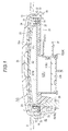
Fig. 1 is a sectional view of an emblem switch; -
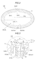
Fig. 2 is a plan view of the emblem switch; -
Fig. 3 is an enlarged sectional view of the vicinity of a joint portion between a first member and a second member configuring an emblem part; and -
Fig. 4 is an enlarged sectional view of the vicinity of a joint portion between a first member and a second member illustrating a waterproof structure of another example. - Hereinafter, an embodiment that is embodied in an emblem switch for a vehicle will be described with reference to the drawings. As illustrated in
Fig. 1 , anemblem switch 1 provided on a vehicle surface S includes anemblem part 2 as an exterior component for a vehicle and an electrostaticcapacitive sensor 3 that is housed on an inside of theemblem part 2. That is, in theemblem switch 1 of the embodiment, the electrostaticcapacitive sensor 3 built in theemblem part 2 detects an object adjacent to adesign surface 2s of theemblem part 2. Thus, a configuration, which functions as a non-contact type sensor switch capable of applying to a door opening and closing device which is able to automatically open and close a vehicle door, a door lock device which is able to perform lock and unlock operations of the vehicle door, and the like by detecting an operation input of a user, is provided. - In addition, as illustrated in
Fig. 2 , theemblem part 2 of the embodiment has the substantially elliptical-shaped design surface 2s. Then, an emblem mark (not illustrated) is three-dimensionally formed in thedesign surface 2s. - As illustrated in
Fig. 1 , in theemblem switch 1 of the embodiment, theemblem part 2 includes a first member (first case member) 11 having thedesign surface 2s and a second member (second case member) 12 forming a housing space X that is sealed between thefirst member 11 and thesecond member 12 in a liquid tight manner by causing thesecond member 12 to be joined to a rear side of thefirst member 11. Then, theemblem part 2 is configured to be installed to an installation recessed portion (hole portion) 15 formed on the vehicle surface S in a state (substantially flush) where thedesign surface 2s slightly protrudes from the vehicle surface S. - In detail, in the
emblem switch 1 of the embodiment, both thefirst member 11 and thesecond member 12 configuring theemblem part 2 are formed by using resin. Thefirst member 11 of the embodiment has a two-layered structure formed of asurface portion 11 a configuring thedesign surface 2s thereof and arear surface portion 11b joined to thesecond member 12. In addition, thesecond member 12 of the embodiment has abody portion 21 having a housing recessedportion 20 and aninner cover member 22 fixed to an opening end of the housing recessedportion 20. In addition, in the embodiment, theinner cover member 22 is fixed to the opening end of the housing recessedportion 20 by adhering, welding, or the like after assembling a housed body within the housing recessedportion 20. Then, theemblem switch 1 of the embodiment is configured to hold asensor electrode 3a and acircuit substrate 3b configuring the electrostaticcapacitive sensor 3 on the inside of the housing recessedportion 20 formed in the housing space X. - Specifically, in the
second member 12 of the embodiment, the housing recessedportion 20 of thebody portion 21 is configured to include a first recessedportion 20a having aside wall portion 24 that forms the opening end of the housing recessedportion 20 and a second recessedportion 20b provided in abottom surface 25 of the first recessedportion 20a to be recessed. Then, thesecond member 12 of the embodiment is configured to hold thesensor electrode 3a of the electrostaticcapacitive sensor 3 on an inside of the first recessedportion 20a and to hold thecircuit substrate 3b of the electrostaticcapacitive sensor 3 on an inside of the second recessedportion 20b. - In addition, in the
second member 12 of the embodiment, a forming portion of the second recessedportion 20b has a shape to protrude substantially in a box shape when viewing thebody portion 21 of thesecond member 12 from a rear side (rear side of thedesign surface 2s and a lower side inFig. 1 ). Furthermore, aconnector portion 27 of theelectrostatic capacitive sensor 3 housed on the inside of theemblem part 2 is formed in a box-shapedportion 26. Then, thesecond member 12 of the embodiment has ascrew stop portion 28 on a side portion of theconnector portion 27. - That is, the
emblem switch 1 of the embodiment is fixed to the inside of the installation recessedportion 15 using thescrew stop portion 28 formed in thesecond member 12. Thus, thesecond member 12 is disposed on the inside of the installation recessedportion 15 and then thesurface portion 11 a of thefirst member 11 configuring thedesign surface 2s is configured to be disposed in a position in which thesurface portion 11a slightly protrudes from the vehicle surface S. - As illustrated in
Figs. 1 to 3 , thesecond member 12 of the embodiment has an annular recessedportion 31 extending over the entire periphery of thesecond member 12 on an outside of the housing recessedportion 20. In the embodiment, the annular recessedportion 31 is formed on an outside of theside wall portion 24 forming the opening end of the housing recessedportion 20 by extending anouter wall portion 32 along theside wall portion 24. In addition, thefirst member 11 of the embodiment has anannular protrusion portion 33 that is extended over the entire periphery of thefirst member 11 along an outer edge of therear surface portion 11 b. Then, theemblem part 2 of the embodiment has a configuration in which thefirst member 11 and thesecond member 12 are assembled in a mode in which theannular protrusion portion 33 on thefirst member 11 side is inserted between theside wall portion 24 and theouter wall portion 32 of the housing recessedportion 20 configuring the annular recessedportion 31 on thesecond member 12 side. - In addition, in the embodiment, the inside of the annular recessed
portion 31 on thesecond member 12 side is filled with elastic adhesive 35 during assembling thefirst member 11 and thesecond member 12. Then, theemblem part 2 of the embodiment has a configuration in which thefirst member 11 and thesecond member 12 are joined based on an adhesive force of theelastic adhesive 35. - That is, in the
emblem part 2 of the embodiment, theelastic adhesive 35 with which the inside of the annular recessedportion 31 is filled fixes theannular protrusion portion 33 inserted into the inside of the annular recessedportion 31 over the entire peripheries of theannular protrusion portion 33 and the annular recessedportion 31. Then, theemblem part 2 of the embodiment is configured to seal the housing space X further on the inner side than ajoint portion 40 between thefirst member 11 and thesecond member 12 formed, as described above, in a liquid tight manner. - More specifically, as illustrated in
Fig. 2 , in the embodiment, theannular protrusion portion 33 on thefirst member 11 side and theside wall portion 24, and theouter wall portion 32 of the housing recessedportion 20 configuring the annular recessedportion 31 on thesecond member 12 side have a substantially elliptical ring shape in accordance with the elliptical shape of thedesign surface 2s. In addition, in the embodiment, therear surface portion 11b of thefirst member 11 and thebody portion 21 of thesecond member 12 are formed by using resin materials different from each other. Then, theelastic adhesive 35 of the embodiment has elasticity so as to allow relative displacement between thefirst member 11 and thesecond member 12 based on a difference in thermal expansion coefficient, even in a post-curing state of theelastic adhesive 35 to fix theannular protrusion portion 33 inserted into the inside of the annular recessedportion 31 as described above. - In addition, in the embodiment, as the
elastic adhesive 35, modified silicon-based adhesive is used. Then, viscosity during coating is set to be a certain degree (for example, substantially 10 to 20 [Pa·s] and substantially that of honey) in which the adhesive evenly spreads over the entire periphery of the annular recessedportion 31 which is filled with the adhesive and jumping thereof does not occur. - In addition, as illustrated in
Fig. 1 , when assembling theemblem switch 1 of the embodiment, therear surface portion 11 b of thefirst member 11 and theinner cover member 22 of thesecond member 12 are fixed by using a double-sidedadhesive tape 42. Thus, it is configured to perform positioning between thefirst member 11 and thesecond member 12, and to enhance the adhesive force. - Furthermore, as illustrated in
Figs. 2 and 3 , in theemblem part 2 of the embodiment, aperiphery wall portion 50 surrounding an outside of thejoint portion 40 joined to thesecond member 12 is formed in therear surface portion 11 b of thefirst member 11. In the embodiment, theperiphery wall portion 50 is formed in a substantially elliptical ring shape extending over the entire periphery of thefirst member 11 in the outermost edge of therear surface portion 11 b. Then, aleading end 50a of theperiphery wall portion 50 extends in a direction (direction from an upper side to a lower side inFigs. 1 and3 ) opposite to the design surface than aleading end 32a of theouter wall portion 32 on thesecond member 12 side. - That is, the
emblem part 2 of the embodiment forms a labyrinth structure in which theannular protrusion portion 33 and theperiphery wall portion 50 on thefirst member 11 side, and theside wall portion 24 and theouter wall portion 32 of the housing recessedportion 20 configuring the annular recessedportion 31 on thesecond member 12 side are entangled with each other. Thus, it becomes a structure ensuring high waterproofness. - As described above, according to the embodiment, it is possible to obtain the following effects.
- (1) the
emblem part 2 as the exterior component for a vehicle includes thefirst member 11 that has thedesign surface 2s disposed on the vehicle surface S and thesecond member 12 that forms the housing space X sealed between thefirst member 11 and thesecond member 12 in a liquid tight manner by being joining to a portion of thefirst member 11 on the rear side. Thesecond member 12 has the annular recessedportion 31 extending over the entire periphery of thesecond member 12. In addition, thefirst member 11 has theannular protrusion portion 33 extending over the entire periphery of thefirst member 11. Furthermore, the inside of the annular recessedportion 31 on thesecond member 12 side is filled with theelastic adhesive 35 during assembling thefirst member 11 and thesecond member 12. Then, theelastic adhesive 35 fixes theannular protrusion portion 33 inserted into the inside of the annular recessedportion 31 over the entire peripheries of theannular protrusion portion 33 and the annular recessedportion 31, and thereby thejoint portion 40 between thefirst member 11 and thesecond member 12 is formed.
According to the configuration described above, thefirst member 11 and thesecond member 12 are evenly joined over the entire peripheries of theannular protrusion portion 33 and the annular recessedportion 31. In addition, the labyrinth structure, in which the annular recessedportion 31 and theannular protrusion portion 33 inserted into the inside of the annular recessedportion 31 are entangled with each other, is formed. Furthermore, the appliedelastic adhesive 35 is held on the inside of the annular recessedportion 31 by the labyrinth structure. Thus, it is possible to secure high waterproofness. In addition, in a case of the related art, dimensions of an external shape are enlarged by increasing fastening portions so as to reduce squeeze unevenness of the O-ring. However, it is possible to avoid the occurrence of such a problem by employing the configuration described above. As a result, it is possible to secure the larger housing space X. Then, for example, it is also possible to apply the configuration to a smaller exterior component for a vehicle such as a button type switch disposed on the vehicle surface S. - (2) The
joint portion 40 between thefirst member 11 and thesecond member 12 has a substantially elliptical ring shape. According to the configuration described above, it is possible to evenly apply theelastic adhesive 35 over the entire periphery of the annular recessedportion 31 configuring thejoint portion 40. In addition, there is an advantage that stress concentration is unlikely to occur when compared to a case where thejoint portion 40 is formed in a polygonal ring shape. Thus, it is possible to secure higher strength. - (3) The
elastic adhesive 35 has elasticity capable of allowing the relative displacement based on the difference in thermal expansion coefficient between thefirst member 11 and thesecond member 12, even in the post-curing state to fix theannular protrusion portion 33 inserted into the inside of the annular recessedportion 31.
That is, if thefirst member 11 and thesecond member 12 configuring theemblem part 2 are formed by using different resin, the relative displacement between the both is likely to occur based on the difference in the thermal expansion coefficient. Thus, the relative displacement based on the difference in the thermal expansion coefficient is likely to occur also by, for example, a temperature difference between an inside and an outside of the vehicle surface S due to direct sunlight and the like in addition to a case where a material-specific thermal expansion coefficient is different. However, according to the configuration described above, theelastic adhesive 35 configuring thejoint portion 40 between thefirst member 11 and thesecond member 12 is elastically deformed, and thereby it is possible to absorb the relative displacement between thefirst member 11 and thesecond member 12. In addition, even if an external force is applied to theemblem part 2, it is possible to absorb the external force. Thus, it is possible to secure high reliability by reducing a load of thefirst member 11 and thesecond member 12 configuring theemblem part 2. - (4) The
periphery wall portion 50 surrounding the outside of thejoint portion 40 between thefirst member 11 and thesecond member 12 is formed in therear surface portion 11 b of thefirst member 11.
According to the configuration described above, thejoint portion 40 is unlikely to be wet by water. In addition, it is possible to form a further complicated labyrinth structure between the wall portions configuring thejoint portion 40, that is, theannular protrusion portion 33 provided on thefirst member 11 side and theside wall portion 24 and theouter wall portion 32 of the housing recessedportion 20 configuring the annular recessedportion 31 provided on thesecond member 12 and theperiphery wall portion 50. Thus, it is possible to secure higher waterproofness. - (5) The
second member 12 includes the housing recessedportion 20 as a holding portion that holds thesensor electrode 3a and thecircuit substrate 3b of theelectrostatic capacitive sensor 3 as the housed body on the inner side than thejoint portion 40 at which thesecond member 12 is joined to thefirst member 11 having an annular shape.
That is, thejoint portion 40 has the structure to allow penetration of water to the outside of theelastic adhesive 35 applied to the inside of the annular recessedportion 31. However, according to the configuration described above, thesensor electrode 3a as the housed body does not overlap with thejoint portion 40 when viewing theemblem switch 1 from thedesign surface 2s side of the emblem part 2 (seeFig. 2 ). Thus, it is possible to secure higher sensor sensitivity by avoiding electric and electromagnetic interference between thesensor electrode 3a and thejoint portion 40. - (6) The
second member 12 has theinner cover member 22 that closes the housing recessedportion 20 by being fixed to the opening end of the housing recessedportion 20. Then, in theemblem part 2, theinner cover member 22 of thesecond member 12 and therear surface portion 11 b of thefirst member 11 are fixed (adhered) by using the double-sidedadhesive tape 42. - According to the configuration described above, the double-sided
adhesive tape 42 functions as a second joint portion. Thus, it is possible to further firmly join thefirst member 11 and thesecond member 12. In addition, accordingly, position deviation between thefirst member 11 and thesecond member 12 is unlikely to occur before theelastic adhesive 35 is cured on the inside of the annular recessedportion 31 by performing positioning during assembling. As a result, it is possible to handle theemblem switch 1 in a temporary assembled state. Thus, it is possible to achieve improvement of working efficiency. - Moreover, the embodiment described above may be changed as below.
- · The embodiment described above is embodied in the
emblem switch 1 in which theelectrostatic capacitive sensor 3 as the housed body is housed on the inside of theemblem part 2 as the exterior component for a vehicle. However, it is not limited to the embodiment and if an exterior component is provided on the vehicle surface S, the embodiment disclosed here may be also applied to the exterior component having any shape, size, and the like. Furthermore, the housed body may be also changed arbitrarily to, for example, an electronic apparatus having a wireless communication antenna and the like. Furthermore, also in this case, it is preferable that a holding portion of the housed body is set further on the inner side than thejoint portion 40 between thefirst member 11 and thesecond member 12 having the annular shapes. Thus, similar to the embodiment described above, even if water penetrates to the outside of theelastic adhesive 35 applied to the inside of the annular recessedportion 31, it is possible to avoid electric and electromagnetic interference between the housed body and the joint portion. Then, the housed body may be other than the electronic apparatus. - · In the embodiment described above, the annular recessed
portion 31 is provided on thesecond member 12 side and theannular protrusion portion 33 is provided on thefirst member 11 side. However, it is not limited to the embodiment. It may be configured to provide the annular recessedportion 31 on thefirst member 11 side, and to provide theannular protrusion portion 33 on thesecond member 12 side. - · In the embodiment described above, the
periphery wall portion 50 provided in therear surface portion 11 b of thefirst member 11 surrounds the outside of thejoint portion 40 between thefirst member 11 and thesecond member 12 in the outermost edge of therear surface portion 11 b. However, it is not limited to the embodiment and it may be configured to provide a plurality of theperiphery wall portions 50. Then, it may also be configured not to have theperiphery wall portion 50. - · In addition, as an
emblem switch 1B (emblem part 2B) illustrated inFig. 4 , afirst member 11B has aflange portion 51 that is continuous to thedesign surface 2s and extends further to the outside (left side inFig. 4 ) than theperiphery wall portion 50. Then, a leadingend 51 a of theflange portion 51 may be configured to face aninner wall surface 15s of the installation recessedportion 15. Water is unlikely to penetrate to the rear side of thedesign surface 2s by providing such a configuration. Thus, it is possible to secure higher waterproofness. In addition, similar to theperiphery wall portion 50, it is preferable that theflange portion 51 is also extended over the entire periphery of thefirst member 11B. In addition, it is preferable that theflange portion 51 is configured such that theleading end 51a faces theinner wall surface 15s of the installation recessedportion 15 in a closer position. Then, in a case where a configuration that does not have theperiphery wall portion 50 is employed, it may be configured to form theflange portion 51 extending further to the outer side than thejoint portion 40 between thefirst member 11 and thesecond member 12. - · In the embodiment described above, the
annular protrusion portion 33 on thefirst member 11 side and theside wall portion 24, and theouter wall portion 32 of the housing recessedportion 20 configuring the annular recessedportion 31 on thesecond member 12 side have substantially elliptical ring shapes in accordance with the elliptical shape of thedesign surface 2s. However, it is not limited to the embodiment and, for example, the ring shape of thejoint portion 40 may be changed arbitrarily such as the polygonal ring shape. However, if spreading when applying theelastic adhesive 35 to the inside of the annular recessedportion 31 and strength of thejoint portion 40, are considered, it is preferable that it is the ring shape. - · The resin material of the
first member 11 and thesecond member 12 configuring theemblem part 2 may be selected arbitrarily. For example, the same resin material may be used. Then, also for composition of theelastic adhesive 35, it is not limited to modified silicon-based adhesive and it may be selected arbitrarily. - · In the embodiment described above, the double-sided
adhesive tape 42 interposed between theinner cover member 22 of thesecond member 12 and therear surface portion 11 b of thefirst member 11 functions as the second joint portion. However, it is not limited to the embodiment and, for example, a member configuring the second joint portion may be changed arbitrarily such as using adhesive capable of attaching or detaching thefirst member 11 and thesecond member 12 at least during curing, or employing a fit structure such as snap fit. In addition, a joint part between thefirst member 11 and thesecond member 12 by the second joint portion may also be changed arbitrarily. For example, the second joint portion may be configured to be set on the outer side than thejoint portion 40 which forms the annular shape. Then, the configuration is not excluded in a configuration in which the second joint portion uses a fastening member. - However, as the embodiment described above, in a case of a configuration in which the electronic apparatus is housed on the inside of the housing space X, it is preferable that the housed body and the second joint portion are configured to have no electric and electromagnetic interference therebetween.
- Next, technical idea which can be grasped from the embodiment described above will be described as advantages.
- (A) The exterior component for a vehicle characterized in that the elastic adhesive has elasticity capable of allowing the relative displacement based on the difference in thermal expansion coefficient between the first member and the second member, even in the after curing state to fix the annular protrusion portion inserted into the inside of the annular recessed portion.
That is, if the first member and the second member are formed by using different resin, the relative displacement between the both is likely to occur based on the difference in the thermal expansion coefficient. Thus, the relative displacement based on the difference in the thermal expansion coefficient is likely to occur also by, for example, a temperature difference between the inside and the outside of the vehicle surface due to direct sunlight and the like in addition to a case where the material-specific thermal expansion coefficient is different. However, according to the configuration described above, the elastic adhesive configuring the joint portion between the first member and the second member is elastically deformed, and thereby it is possible to absorb the relative displacement between the first member and the second member. In addition, even if the external force is applied to the exterior component for a vehicle, it is possible to absorb the external force. Thus, it is possible to secure high reliability by reducing a load of the first member and the second member. - (B) The exterior component for a vehicle characterized in that the joint portion has the ring shape.
According to the configuration described above, it is possible to apply the elastic adhesive evenly over the entire periphery of the annular recessed portion configuring the joint portion. In addition, there is an advantage that stress concentration is unlikely to occur when compared to a case where the joint portion is formed in a polygonal ring shape. Thus, it is possible to secure higher strength. - (C) The exterior component for a vehicle characterized in that the second joint portion is configured of the double-sided adhesive tape. Thus, it is possible to form the second joint portion having a simple configuration and that is easy to handle.
The principles, preferred embodiment and mode of operation of the present invention have been described in the foregoing specification. However, the invention which is intended to be protected is not to be construed as limited to the particular embodiments disclosed. Further, the embodiments described herein are to be regarded as illustrative rather than restrictive. Variations and changes may be made by others, and equivalents employed, without departing from the spirit of the present invention. Accordingly, it is expressly intended that all such variations, changes and equivalents which fall within the spirit and scope of the present invention as defined in the claims, be embraced thereby. - An exterior component (2) for a vehicle includes: a first member (11, 11 B) having a design surface (2s) disposed on a vehicle surface; and a second member (12) forming a housing space (20) sealed between the first and second members in a liquid tight manner by being joined to the first member on a rear side of the design surface, wherein a joint portion (40) between the first member and the second member is configured of an annular recessed portion (31) provided on one side of the first and second members, an annular protrusion portion (33) provided on the other side of the first and second members, and elastic adhesive (35) with which an inside of the annular recessed portion is filled thereby fixing the annular protrusion portion inserted into the inside of the annular recessed portion over the entire peripheries of the annular protrusion and annular recessed portions.
Claims (9)
- An exterior component (2) for a vehicle comprising:a first member (11, 11 B) that has a design surface (2s) disposed on a vehicle surface; anda second member (12) that forms a housing space (20) which is sealed between the first member and the second member in a liquid tight manner by being joined to the first member on a rear side of the design surface,wherein a joint portion (40) between the first member and the second member is configured ofan annular recessed portion (31) that is provided on one side of the first member and the second member,an annular protrusion portion (33) that is provided on the other side of the first member and the second member, andelastic adhesive (35) with which an inside of the annular recessed portion is filled thereby fixing the annular protrusion portion inserted into the inside of the annular recessed portion over the entire peripheries of the annular protrusion portion and the annular recessed portion.
- The exterior component for a vehicle according to claim 1,
wherein the first member includes a peripheral wall portion (50) surrounding an outside of the joint portion on the rear side of the design surface. - The exterior component for a vehicle according to claim 1 or 2,
wherein the second member is disposed on an inside of an installation recessed portion (15) formed on the vehicle surface, and
wherein the first member has a flange portion (51) whose leading end (51 a) faces an inner wall surface (15s) of the installation recessed portion by being continuous to the design surface and extending further to an outer side than the joint portion. - The exterior component for a vehicle according to any one of claims 1 to 3, further comprising:a holding portion (20) of a housed body (3, 3a) further on an inner side than the joint portion.
- The exterior component for a vehicle according to any one of claims 1 to 4,
wherein the elastic adhesive has elasticity capable of allowing relative displacement based on a difference in thermal expansion coefficient between the first member and the second member, even in a post-curing state to fix the annular protrusion portion inserted into the inside of the annular recessed portion. - The exterior component for a vehicle according to any one of claims 1 to 5,
wherein the joint portion has a ring shape. - The exterior component for a vehicle according to any one of claims 1 to 6, further comprising
a second joint portion (42) joining the first member and the second member. - The exterior component for a vehicle according to claim 7,
wherein the second joint portion joins the first member and the second member within the housing space on an inner side than the annular recessed portion. - The exterior component for a vehicle according to claim 7 or 8,
wherein the second joint portion is a double-sided adhesive tape (42).
Applications Claiming Priority (1)
| Application Number | Priority Date | Filing Date | Title |
|---|---|---|---|
| JP2015065165A JP2016182922A (en) | 2015-03-26 | 2015-03-26 | Exterior parts for vehicles |
Publications (2)
| Publication Number | Publication Date |
|---|---|
| EP3072746A1 true EP3072746A1 (en) | 2016-09-28 |
| EP3072746B1 EP3072746B1 (en) | 2020-04-22 |
Family
ID=55527314
Family Applications (1)
| Application Number | Title | Priority Date | Filing Date |
|---|---|---|---|
| EP16159184.7A Not-in-force EP3072746B1 (en) | 2015-03-26 | 2016-03-08 | Exterior component for a vehicle |
Country Status (4)
| Country | Link |
|---|---|
| US (1) | US9630574B2 (en) |
| EP (1) | EP3072746B1 (en) |
| JP (1) | JP2016182922A (en) |
| CN (1) | CN205554077U (en) |
Cited By (1)
| Publication number | Priority date | Publication date | Assignee | Title |
|---|---|---|---|---|
| DE102021209609B3 (en) | 2021-09-01 | 2023-01-12 | Volkswagen Aktiengesellschaft | Functional arrangement for a motor vehicle |
Families Citing this family (9)
| Publication number | Priority date | Publication date | Assignee | Title |
|---|---|---|---|---|
| US9860430B1 (en) * | 2017-03-10 | 2018-01-02 | Honda Motor Co., Ltd. | Emblem cover assembly |
| JP2019077263A (en) * | 2017-10-23 | 2019-05-23 | 株式会社ユーシン | Vehicle rear module device |
| JP6704025B2 (en) * | 2018-09-27 | 2020-06-03 | 本田技研工業株式会社 | Body front structure |
| CN111071165B (en) * | 2018-10-22 | 2023-04-21 | 丰田合成株式会社 | Millimeter wave radar unit and installation method thereof |
| JP7070323B2 (en) * | 2018-10-22 | 2022-05-18 | 豊田合成株式会社 | Millimeter wave radar unit |
| US12270912B2 (en) * | 2019-03-27 | 2025-04-08 | Toyoda Gosei Co., Ltd. | Structure for mounting near infrared sensor and sensor cover to vehicle |
| JP7243681B2 (en) * | 2020-05-26 | 2023-03-22 | 豊田合成株式会社 | Exterior parts for vehicles |
| CN116331138A (en) * | 2021-12-23 | 2023-06-27 | 本田技研工业株式会社 | Body structure |
| JP7812735B2 (en) * | 2022-05-20 | 2026-02-10 | トヨタ自動車株式会社 | Waterproof structure of exterior display |
Citations (3)
| Publication number | Priority date | Publication date | Assignee | Title |
|---|---|---|---|---|
| JP2009282068A (en) | 2008-05-19 | 2009-12-03 | Fujinon Corp | Lens assembly and imaging apparatus |
| US20130196089A1 (en) * | 2012-01-30 | 2013-08-01 | GM Global Technology Operations LLC | Emblem assembly and method of forming same |
| DE102013001321A1 (en) * | 2013-01-25 | 2014-07-31 | Audi Ag | Arrangement for attaching decorative element to bodywork of motor vehicle, has cylindrical connection elements, where decorative element is insertable in recesses formed in cylindrical connection elements |
Family Cites Families (15)
| Publication number | Priority date | Publication date | Assignee | Title |
|---|---|---|---|---|
| CN101137484B (en) * | 2005-03-15 | 2010-09-29 | 株式会社美姿把 | Film-forming article, film-forming method, and film-forming apparatus |
| US8530028B2 (en) * | 2007-01-05 | 2013-09-10 | Johnson Controls Technology Company | Localized deep soft area of a trim panel |
| JP5040607B2 (en) * | 2007-11-16 | 2012-10-03 | 豊田合成株式会社 | Emblem and its mounting structure |
| US7815237B2 (en) * | 2008-01-09 | 2010-10-19 | Toyota Motor Engineering & Manufacturing North America, Inc. | Covers for vehicle instrument panels |
| JP4983756B2 (en) * | 2008-09-17 | 2012-07-25 | アイシン・エィ・ダブリュ株式会社 | Electronic circuit equipment |
| JP2010108829A (en) | 2008-10-31 | 2010-05-13 | Furukawa Electric Co Ltd:The | Connecting part and connecting method of conductor and terminal |
| US8205923B2 (en) * | 2010-09-20 | 2012-06-26 | GM Global Technology Operations LLC | Retaining clip for ditch molding |
| US8816586B2 (en) * | 2011-04-11 | 2014-08-26 | Cmarlite, Llc | Illuminated devices attached to vehicles |
| US8922655B2 (en) * | 2011-10-28 | 2014-12-30 | Nissan North America, Inc. | Vehicle front grille assembly |
| WO2014120757A1 (en) * | 2013-01-29 | 2014-08-07 | Tk Holdings Inc. | Illuminated emblem assembly for connection to an airbag cover |
| US9376055B2 (en) * | 2014-02-24 | 2016-06-28 | Nissan North America, Inc. | Illuminated emblem |
| US20150241015A1 (en) * | 2014-02-24 | 2015-08-27 | Nissan North America, Inc. | Illuminated Emblem |
| US9358935B2 (en) * | 2014-09-23 | 2016-06-07 | Toyota Motor Engineering & Manufacturing North America, Inc. | Roof drip molding attachment |
| DE102015000465A1 (en) * | 2015-01-15 | 2016-07-21 | GM Global Technology Operations LLC (n. d. Ges. d. Staates Delaware) | SWITCHING DEVICE AND MOTOR VEHICLE |
| KR101745091B1 (en) * | 2015-05-22 | 2017-06-08 | 현대자동차주식회사 | Emblem integrated trunk switch module |
-
2015
- 2015-03-26 JP JP2015065165A patent/JP2016182922A/en active Pending
-
2016
- 2016-03-08 EP EP16159184.7A patent/EP3072746B1/en not_active Not-in-force
- 2016-03-15 US US15/070,552 patent/US9630574B2/en not_active Expired - Fee Related
- 2016-03-24 CN CN201620232376.XU patent/CN205554077U/en not_active Expired - Fee Related
Patent Citations (3)
| Publication number | Priority date | Publication date | Assignee | Title |
|---|---|---|---|---|
| JP2009282068A (en) | 2008-05-19 | 2009-12-03 | Fujinon Corp | Lens assembly and imaging apparatus |
| US20130196089A1 (en) * | 2012-01-30 | 2013-08-01 | GM Global Technology Operations LLC | Emblem assembly and method of forming same |
| DE102013001321A1 (en) * | 2013-01-25 | 2014-07-31 | Audi Ag | Arrangement for attaching decorative element to bodywork of motor vehicle, has cylindrical connection elements, where decorative element is insertable in recesses formed in cylindrical connection elements |
Cited By (1)
| Publication number | Priority date | Publication date | Assignee | Title |
|---|---|---|---|---|
| DE102021209609B3 (en) | 2021-09-01 | 2023-01-12 | Volkswagen Aktiengesellschaft | Functional arrangement for a motor vehicle |
Also Published As
| Publication number | Publication date |
|---|---|
| JP2016182922A (en) | 2016-10-20 |
| US9630574B2 (en) | 2017-04-25 |
| CN205554077U (en) | 2016-09-07 |
| EP3072746B1 (en) | 2020-04-22 |
| US20160280154A1 (en) | 2016-09-29 |
Similar Documents
| Publication | Publication Date | Title |
|---|---|---|
| EP3072746B1 (en) | Exterior component for a vehicle | |
| US9013889B2 (en) | Electronic controller | |
| JP2011204974A (en) | Electronic controller | |
| US20130020747A1 (en) | Cushion of folding portable electronic device and waterproof structure of folding portable electronic device | |
| KR20210012237A (en) | Battery case | |
| CN109392260B (en) | Electronic device mounted on industrial equipment | |
| US20150145384A1 (en) | Apparatus and method for providing a seal around a perimeter of a bi-material enclosure | |
| JP2018160538A (en) | Electronics | |
| WO2016167109A1 (en) | Waterproofing structure for electronic control unit | |
| JP2008215959A (en) | Radio equipment for water meter | |
| CN210515974U (en) | Screen protection structure of electronic equipment and electronic equipment | |
| JP5258031B2 (en) | Connection flexible wiring board, waterproof mounting structure and waterproof mounting method for the wiring board, and waterproof portable electronic terminal | |
| JP2012200061A (en) | Method for fabricating watertight case, watertight case and on-vehicle electronic apparatus | |
| CN103096659A (en) | Front unit of display device | |
| KR101589174B1 (en) | Wire Harness Connector with Waterproof Function and a Method of Manufacturing | |
| KR102371489B1 (en) | Remote controller with waterproof structure | |
| KR200496947Y1 (en) | Charging connector having a structure for fixing thermocouple | |
| US10618245B2 (en) | Flexible laminated structure and display | |
| KR102352707B1 (en) | Wiring harness | |
| JP2014184897A (en) | Grommet | |
| CN205179115U (en) | Communication device | |
| JP2019097339A (en) | Protection component and protection method | |
| JP2017028109A (en) | Seal member and seal structure | |
| JP2016035803A (en) | Electronic device connector having a single-layer thermosetting resin waterproofing member | |
| WO2018105311A1 (en) | Electronic key |
Legal Events
| Date | Code | Title | Description |
|---|---|---|---|
| PUAI | Public reference made under article 153(3) epc to a published international application that has entered the european phase |
Free format text: ORIGINAL CODE: 0009012 |
|
| AK | Designated contracting states |
Kind code of ref document: A1 Designated state(s): AL AT BE BG CH CY CZ DE DK EE ES FI FR GB GR HR HU IE IS IT LI LT LU LV MC MK MT NL NO PL PT RO RS SE SI SK SM TR |
|
| AX | Request for extension of the european patent |
Extension state: BA ME |
|
| STAA | Information on the status of an ep patent application or granted ep patent |
Free format text: STATUS: REQUEST FOR EXAMINATION WAS MADE |
|
| 17P | Request for examination filed |
Effective date: 20170324 |
|
| RBV | Designated contracting states (corrected) |
Designated state(s): AL AT BE BG CH CY CZ DE DK EE ES FI FR GB GR HR HU IE IS IT LI LT LU LV MC MK MT NL NO PL PT RO RS SE SI SK SM TR |
|
| STAA | Information on the status of an ep patent application or granted ep patent |
Free format text: STATUS: EXAMINATION IS IN PROGRESS |
|
| 17Q | First examination report despatched |
Effective date: 20180315 |
|
| GRAP | Despatch of communication of intention to grant a patent |
Free format text: ORIGINAL CODE: EPIDOSNIGR1 |
|
| STAA | Information on the status of an ep patent application or granted ep patent |
Free format text: STATUS: GRANT OF PATENT IS INTENDED |
|
| INTG | Intention to grant announced |
Effective date: 20191024 |
|
| GRAS | Grant fee paid |
Free format text: ORIGINAL CODE: EPIDOSNIGR3 |
|
| GRAA | (expected) grant |
Free format text: ORIGINAL CODE: 0009210 |
|
| STAA | Information on the status of an ep patent application or granted ep patent |
Free format text: STATUS: THE PATENT HAS BEEN GRANTED |
|
| AK | Designated contracting states |
Kind code of ref document: B1 Designated state(s): AL AT BE BG CH CY CZ DE DK EE ES FI FR GB GR HR HU IE IS IT LI LT LU LV MC MK MT NL NO PL PT RO RS SE SI SK SM TR |
|
| REG | Reference to a national code |
Ref country code: CH Ref legal event code: EP |
|
| REG | Reference to a national code |
Ref country code: IE Ref legal event code: FG4D |
|
| REG | Reference to a national code |
Ref country code: DE Ref legal event code: R096 Ref document number: 602016034353 Country of ref document: DE |
|
| REG | Reference to a national code |
Ref country code: AT Ref legal event code: REF Ref document number: 1259675 Country of ref document: AT Kind code of ref document: T Effective date: 20200515 |
|
| REG | Reference to a national code |
Ref country code: LT Ref legal event code: MG4D |
|
| REG | Reference to a national code |
Ref country code: NL Ref legal event code: MP Effective date: 20200422 |
|
| PG25 | Lapsed in a contracting state [announced via postgrant information from national office to epo] |
Ref country code: NO Free format text: LAPSE BECAUSE OF FAILURE TO SUBMIT A TRANSLATION OF THE DESCRIPTION OR TO PAY THE FEE WITHIN THE PRESCRIBED TIME-LIMIT Effective date: 20200722 Ref country code: PT Free format text: LAPSE BECAUSE OF FAILURE TO SUBMIT A TRANSLATION OF THE DESCRIPTION OR TO PAY THE FEE WITHIN THE PRESCRIBED TIME-LIMIT Effective date: 20200824 Ref country code: FI Free format text: LAPSE BECAUSE OF FAILURE TO SUBMIT A TRANSLATION OF THE DESCRIPTION OR TO PAY THE FEE WITHIN THE PRESCRIBED TIME-LIMIT Effective date: 20200422 Ref country code: LT Free format text: LAPSE BECAUSE OF FAILURE TO SUBMIT A TRANSLATION OF THE DESCRIPTION OR TO PAY THE FEE WITHIN THE PRESCRIBED TIME-LIMIT Effective date: 20200422 Ref country code: IS Free format text: LAPSE BECAUSE OF FAILURE TO SUBMIT A TRANSLATION OF THE DESCRIPTION OR TO PAY THE FEE WITHIN THE PRESCRIBED TIME-LIMIT Effective date: 20200822 Ref country code: SE Free format text: LAPSE BECAUSE OF FAILURE TO SUBMIT A TRANSLATION OF THE DESCRIPTION OR TO PAY THE FEE WITHIN THE PRESCRIBED TIME-LIMIT Effective date: 20200422 Ref country code: GR Free format text: LAPSE BECAUSE OF FAILURE TO SUBMIT A TRANSLATION OF THE DESCRIPTION OR TO PAY THE FEE WITHIN THE PRESCRIBED TIME-LIMIT Effective date: 20200723 Ref country code: NL Free format text: LAPSE BECAUSE OF FAILURE TO SUBMIT A TRANSLATION OF THE DESCRIPTION OR TO PAY THE FEE WITHIN THE PRESCRIBED TIME-LIMIT Effective date: 20200422 |
|
| REG | Reference to a national code |
Ref country code: AT Ref legal event code: MK05 Ref document number: 1259675 Country of ref document: AT Kind code of ref document: T Effective date: 20200422 |
|
| PG25 | Lapsed in a contracting state [announced via postgrant information from national office to epo] |
Ref country code: RS Free format text: LAPSE BECAUSE OF FAILURE TO SUBMIT A TRANSLATION OF THE DESCRIPTION OR TO PAY THE FEE WITHIN THE PRESCRIBED TIME-LIMIT Effective date: 20200422 Ref country code: LV Free format text: LAPSE BECAUSE OF FAILURE TO SUBMIT A TRANSLATION OF THE DESCRIPTION OR TO PAY THE FEE WITHIN THE PRESCRIBED TIME-LIMIT Effective date: 20200422 Ref country code: HR Free format text: LAPSE BECAUSE OF FAILURE TO SUBMIT A TRANSLATION OF THE DESCRIPTION OR TO PAY THE FEE WITHIN THE PRESCRIBED TIME-LIMIT Effective date: 20200422 Ref country code: BG Free format text: LAPSE BECAUSE OF FAILURE TO SUBMIT A TRANSLATION OF THE DESCRIPTION OR TO PAY THE FEE WITHIN THE PRESCRIBED TIME-LIMIT Effective date: 20200722 |
|
| PG25 | Lapsed in a contracting state [announced via postgrant information from national office to epo] |
Ref country code: AL Free format text: LAPSE BECAUSE OF FAILURE TO SUBMIT A TRANSLATION OF THE DESCRIPTION OR TO PAY THE FEE WITHIN THE PRESCRIBED TIME-LIMIT Effective date: 20200422 |
|
| REG | Reference to a national code |
Ref country code: DE Ref legal event code: R097 Ref document number: 602016034353 Country of ref document: DE |
|
| PG25 | Lapsed in a contracting state [announced via postgrant information from national office to epo] |
Ref country code: ES Free format text: LAPSE BECAUSE OF FAILURE TO SUBMIT A TRANSLATION OF THE DESCRIPTION OR TO PAY THE FEE WITHIN THE PRESCRIBED TIME-LIMIT Effective date: 20200422 Ref country code: DK Free format text: LAPSE BECAUSE OF FAILURE TO SUBMIT A TRANSLATION OF THE DESCRIPTION OR TO PAY THE FEE WITHIN THE PRESCRIBED TIME-LIMIT Effective date: 20200422 Ref country code: SM Free format text: LAPSE BECAUSE OF FAILURE TO SUBMIT A TRANSLATION OF THE DESCRIPTION OR TO PAY THE FEE WITHIN THE PRESCRIBED TIME-LIMIT Effective date: 20200422 Ref country code: CZ Free format text: LAPSE BECAUSE OF FAILURE TO SUBMIT A TRANSLATION OF THE DESCRIPTION OR TO PAY THE FEE WITHIN THE PRESCRIBED TIME-LIMIT Effective date: 20200422 Ref country code: AT Free format text: LAPSE BECAUSE OF FAILURE TO SUBMIT A TRANSLATION OF THE DESCRIPTION OR TO PAY THE FEE WITHIN THE PRESCRIBED TIME-LIMIT Effective date: 20200422 Ref country code: IT Free format text: LAPSE BECAUSE OF FAILURE TO SUBMIT A TRANSLATION OF THE DESCRIPTION OR TO PAY THE FEE WITHIN THE PRESCRIBED TIME-LIMIT Effective date: 20200422 Ref country code: EE Free format text: LAPSE BECAUSE OF FAILURE TO SUBMIT A TRANSLATION OF THE DESCRIPTION OR TO PAY THE FEE WITHIN THE PRESCRIBED TIME-LIMIT Effective date: 20200422 Ref country code: RO Free format text: LAPSE BECAUSE OF FAILURE TO SUBMIT A TRANSLATION OF THE DESCRIPTION OR TO PAY THE FEE WITHIN THE PRESCRIBED TIME-LIMIT Effective date: 20200422 |
|
| PG25 | Lapsed in a contracting state [announced via postgrant information from national office to epo] |
Ref country code: PL Free format text: LAPSE BECAUSE OF FAILURE TO SUBMIT A TRANSLATION OF THE DESCRIPTION OR TO PAY THE FEE WITHIN THE PRESCRIBED TIME-LIMIT Effective date: 20200422 Ref country code: SK Free format text: LAPSE BECAUSE OF FAILURE TO SUBMIT A TRANSLATION OF THE DESCRIPTION OR TO PAY THE FEE WITHIN THE PRESCRIBED TIME-LIMIT Effective date: 20200422 |
|
| PLBE | No opposition filed within time limit |
Free format text: ORIGINAL CODE: 0009261 |
|
| STAA | Information on the status of an ep patent application or granted ep patent |
Free format text: STATUS: NO OPPOSITION FILED WITHIN TIME LIMIT |
|
| 26N | No opposition filed |
Effective date: 20210125 |
|
| PGFP | Annual fee paid to national office [announced via postgrant information from national office to epo] |
Ref country code: FR Payment date: 20210210 Year of fee payment: 6 |
|
| PG25 | Lapsed in a contracting state [announced via postgrant information from national office to epo] |
Ref country code: SI Free format text: LAPSE BECAUSE OF FAILURE TO SUBMIT A TRANSLATION OF THE DESCRIPTION OR TO PAY THE FEE WITHIN THE PRESCRIBED TIME-LIMIT Effective date: 20200422 |
|
| REG | Reference to a national code |
Ref country code: DE Ref legal event code: R119 Ref document number: 602016034353 Country of ref document: DE |
|
| PG25 | Lapsed in a contracting state [announced via postgrant information from national office to epo] |
Ref country code: MC Free format text: LAPSE BECAUSE OF FAILURE TO SUBMIT A TRANSLATION OF THE DESCRIPTION OR TO PAY THE FEE WITHIN THE PRESCRIBED TIME-LIMIT Effective date: 20200422 |
|
| REG | Reference to a national code |
Ref country code: CH Ref legal event code: PL |
|
| GBPC | Gb: european patent ceased through non-payment of renewal fee |
Effective date: 20210308 |
|
| REG | Reference to a national code |
Ref country code: BE Ref legal event code: MM Effective date: 20210331 |
|
| PG25 | Lapsed in a contracting state [announced via postgrant information from national office to epo] |
Ref country code: LU Free format text: LAPSE BECAUSE OF NON-PAYMENT OF DUE FEES Effective date: 20210308 Ref country code: LI Free format text: LAPSE BECAUSE OF NON-PAYMENT OF DUE FEES Effective date: 20210331 Ref country code: CH Free format text: LAPSE BECAUSE OF NON-PAYMENT OF DUE FEES Effective date: 20210331 Ref country code: DE Free format text: LAPSE BECAUSE OF NON-PAYMENT OF DUE FEES Effective date: 20211001 Ref country code: IE Free format text: LAPSE BECAUSE OF NON-PAYMENT OF DUE FEES Effective date: 20210308 Ref country code: GB Free format text: LAPSE BECAUSE OF NON-PAYMENT OF DUE FEES Effective date: 20210308 |
|
| PG25 | Lapsed in a contracting state [announced via postgrant information from national office to epo] |
Ref country code: BE Free format text: LAPSE BECAUSE OF NON-PAYMENT OF DUE FEES Effective date: 20210331 |
|
| PG25 | Lapsed in a contracting state [announced via postgrant information from national office to epo] |
Ref country code: FR Free format text: LAPSE BECAUSE OF NON-PAYMENT OF DUE FEES Effective date: 20220331 |
|
| PG25 | Lapsed in a contracting state [announced via postgrant information from national office to epo] |
Ref country code: HU Free format text: LAPSE BECAUSE OF FAILURE TO SUBMIT A TRANSLATION OF THE DESCRIPTION OR TO PAY THE FEE WITHIN THE PRESCRIBED TIME-LIMIT; INVALID AB INITIO Effective date: 20160308 |
|
| PG25 | Lapsed in a contracting state [announced via postgrant information from national office to epo] |
Ref country code: CY Free format text: LAPSE BECAUSE OF FAILURE TO SUBMIT A TRANSLATION OF THE DESCRIPTION OR TO PAY THE FEE WITHIN THE PRESCRIBED TIME-LIMIT Effective date: 20200422 |
|
| PG25 | Lapsed in a contracting state [announced via postgrant information from national office to epo] |
Ref country code: MK Free format text: LAPSE BECAUSE OF FAILURE TO SUBMIT A TRANSLATION OF THE DESCRIPTION OR TO PAY THE FEE WITHIN THE PRESCRIBED TIME-LIMIT Effective date: 20200422 |
|
| PG25 | Lapsed in a contracting state [announced via postgrant information from national office to epo] |
Ref country code: TR Free format text: LAPSE BECAUSE OF FAILURE TO SUBMIT A TRANSLATION OF THE DESCRIPTION OR TO PAY THE FEE WITHIN THE PRESCRIBED TIME-LIMIT Effective date: 20200422 |
|
| PG25 | Lapsed in a contracting state [announced via postgrant information from national office to epo] |
Ref country code: MT Free format text: LAPSE BECAUSE OF FAILURE TO SUBMIT A TRANSLATION OF THE DESCRIPTION OR TO PAY THE FEE WITHIN THE PRESCRIBED TIME-LIMIT Effective date: 20200422 |