EP3072025B1 - System and method for automatically generating vehicle guidance waypoints and waylines - Google Patents
System and method for automatically generating vehicle guidance waypoints and waylines Download PDFInfo
- Publication number
- EP3072025B1 EP3072025B1 EP14810062.1A EP14810062A EP3072025B1 EP 3072025 B1 EP3072025 B1 EP 3072025B1 EP 14810062 A EP14810062 A EP 14810062A EP 3072025 B1 EP3072025 B1 EP 3072025B1
- Authority
- EP
- European Patent Office
- Prior art keywords
- waypoints
- path
- controller
- wayline
- guidance system
- Prior art date
- Legal status (The legal status is an assumption and is not a legal conclusion. Google has not performed a legal analysis and makes no representation as to the accuracy of the status listed.)
- Active
Links
Images




Classifications
-
- A—HUMAN NECESSITIES
- A01—AGRICULTURE; FORESTRY; ANIMAL HUSBANDRY; HUNTING; TRAPPING; FISHING
- A01B—SOIL WORKING IN AGRICULTURE OR FORESTRY; PARTS, DETAILS, OR ACCESSORIES OF AGRICULTURAL MACHINES OR IMPLEMENTS, IN GENERAL
- A01B69/00—Steering of agricultural machines or implements; Guiding agricultural machines or implements on a desired track
- A01B69/007—Steering or guiding of agricultural vehicles, e.g. steering of the tractor to keep the plough in the furrow
- A01B69/008—Steering or guiding of agricultural vehicles, e.g. steering of the tractor to keep the plough in the furrow automatic
-
- A—HUMAN NECESSITIES
- A01—AGRICULTURE; FORESTRY; ANIMAL HUSBANDRY; HUNTING; TRAPPING; FISHING
- A01B—SOIL WORKING IN AGRICULTURE OR FORESTRY; PARTS, DETAILS, OR ACCESSORIES OF AGRICULTURAL MACHINES OR IMPLEMENTS, IN GENERAL
- A01B69/00—Steering of agricultural machines or implements; Guiding agricultural machines or implements on a desired track
-
- B—PERFORMING OPERATIONS; TRANSPORTING
- B60—VEHICLES IN GENERAL
- B60K—ARRANGEMENT OR MOUNTING OF PROPULSION UNITS OR OF TRANSMISSIONS IN VEHICLES; ARRANGEMENT OR MOUNTING OF PLURAL DIVERSE PRIME-MOVERS IN VEHICLES; AUXILIARY DRIVES FOR VEHICLES; INSTRUMENTATION OR DASHBOARDS FOR VEHICLES; ARRANGEMENTS IN CONNECTION WITH COOLING, AIR INTAKE, GAS EXHAUST OR FUEL SUPPLY OF PROPULSION UNITS IN VEHICLES
- B60K35/00—Instruments specially adapted for vehicles; Arrangement of instruments in or on vehicles
- B60K35/10—Input arrangements, i.e. from user to vehicle, associated with vehicle functions or specially adapted therefor
-
- B—PERFORMING OPERATIONS; TRANSPORTING
- B60—VEHICLES IN GENERAL
- B60K—ARRANGEMENT OR MOUNTING OF PROPULSION UNITS OR OF TRANSMISSIONS IN VEHICLES; ARRANGEMENT OR MOUNTING OF PLURAL DIVERSE PRIME-MOVERS IN VEHICLES; AUXILIARY DRIVES FOR VEHICLES; INSTRUMENTATION OR DASHBOARDS FOR VEHICLES; ARRANGEMENTS IN CONNECTION WITH COOLING, AIR INTAKE, GAS EXHAUST OR FUEL SUPPLY OF PROPULSION UNITS IN VEHICLES
- B60K35/00—Instruments specially adapted for vehicles; Arrangement of instruments in or on vehicles
- B60K35/20—Output arrangements, i.e. from vehicle to user, associated with vehicle functions or specially adapted therefor
- B60K35/21—Output arrangements, i.e. from vehicle to user, associated with vehicle functions or specially adapted therefor using visual output, e.g. blinking lights or matrix displays
- B60K35/22—Display screens
-
- B—PERFORMING OPERATIONS; TRANSPORTING
- B60—VEHICLES IN GENERAL
- B60K—ARRANGEMENT OR MOUNTING OF PROPULSION UNITS OR OF TRANSMISSIONS IN VEHICLES; ARRANGEMENT OR MOUNTING OF PLURAL DIVERSE PRIME-MOVERS IN VEHICLES; AUXILIARY DRIVES FOR VEHICLES; INSTRUMENTATION OR DASHBOARDS FOR VEHICLES; ARRANGEMENTS IN CONNECTION WITH COOLING, AIR INTAKE, GAS EXHAUST OR FUEL SUPPLY OF PROPULSION UNITS IN VEHICLES
- B60K35/00—Instruments specially adapted for vehicles; Arrangement of instruments in or on vehicles
- B60K35/65—Instruments specially adapted for specific vehicle types or users, e.g. for left- or right-hand drive
-
- G—PHYSICS
- G01—MEASURING; TESTING
- G01C—MEASURING DISTANCES, LEVELS OR BEARINGS; SURVEYING; NAVIGATION; GYROSCOPIC INSTRUMENTS; PHOTOGRAMMETRY OR VIDEOGRAMMETRY
- G01C21/00—Navigation; Navigational instruments not provided for in groups G01C1/00 - G01C19/00
- G01C21/26—Navigation; Navigational instruments not provided for in groups G01C1/00 - G01C19/00 specially adapted for navigation in a road network
- G01C21/34—Route searching; Route guidance
- G01C21/3407—Route searching; Route guidance specially adapted for specific applications
- G01C21/343—Calculating itineraries
-
- G—PHYSICS
- G01—MEASURING; TESTING
- G01C—MEASURING DISTANCES, LEVELS OR BEARINGS; SURVEYING; NAVIGATION; GYROSCOPIC INSTRUMENTS; PHOTOGRAMMETRY OR VIDEOGRAMMETRY
- G01C21/00—Navigation; Navigational instruments not provided for in groups G01C1/00 - G01C19/00
- G01C21/26—Navigation; Navigational instruments not provided for in groups G01C1/00 - G01C19/00 specially adapted for navigation in a road network
- G01C21/34—Route searching; Route guidance
- G01C21/36—Input/output arrangements for on-board computers
- G01C21/3626—Details of the output of route guidance instructions
-
- G—PHYSICS
- G01—MEASURING; TESTING
- G01C—MEASURING DISTANCES, LEVELS OR BEARINGS; SURVEYING; NAVIGATION; GYROSCOPIC INSTRUMENTS; PHOTOGRAMMETRY OR VIDEOGRAMMETRY
- G01C21/00—Navigation; Navigational instruments not provided for in groups G01C1/00 - G01C19/00
- G01C21/26—Navigation; Navigational instruments not provided for in groups G01C1/00 - G01C19/00 specially adapted for navigation in a road network
- G01C21/34—Route searching; Route guidance
- G01C21/36—Input/output arrangements for on-board computers
- G01C21/3664—Details of the user input interface, e.g. buttons, knobs or sliders, including those provided on a touch screen; remote controllers; input using gestures
-
- G—PHYSICS
- G05—CONTROLLING; REGULATING
- G05D—SYSTEMS FOR CONTROLLING OR REGULATING NON-ELECTRIC VARIABLES
- G05D1/00—Control of position, course, altitude or attitude of land, water, air or space vehicles, e.g. using automatic pilots
- G05D1/02—Control of position or course in two dimensions
- G05D1/021—Control of position or course in two dimensions specially adapted to land vehicles
- G05D1/0212—Control of position or course in two dimensions specially adapted to land vehicles with means for defining a desired trajectory
- G05D1/0219—Control of position or course in two dimensions specially adapted to land vehicles with means for defining a desired trajectory ensuring the processing of the whole working surface
-
- G—PHYSICS
- G05—CONTROLLING; REGULATING
- G05D—SYSTEMS FOR CONTROLLING OR REGULATING NON-ELECTRIC VARIABLES
- G05D1/00—Control of position, course, altitude or attitude of land, water, air or space vehicles, e.g. using automatic pilots
- G05D1/02—Control of position or course in two dimensions
- G05D1/021—Control of position or course in two dimensions specially adapted to land vehicles
- G05D1/0268—Control of position or course in two dimensions specially adapted to land vehicles using internal positioning means
- G05D1/0274—Control of position or course in two dimensions specially adapted to land vehicles using internal positioning means using mapping information stored in a memory device
-
- G—PHYSICS
- G05—CONTROLLING; REGULATING
- G05D—SYSTEMS FOR CONTROLLING OR REGULATING NON-ELECTRIC VARIABLES
- G05D1/00—Control of position, course, altitude or attitude of land, water, air or space vehicles, e.g. using automatic pilots
- G05D1/02—Control of position or course in two dimensions
- G05D1/021—Control of position or course in two dimensions specially adapted to land vehicles
- G05D1/0276—Control of position or course in two dimensions specially adapted to land vehicles using signals provided by a source external to the vehicle
- G05D1/0278—Control of position or course in two dimensions specially adapted to land vehicles using signals provided by a source external to the vehicle using satellite positioning signals, e.g. GPS
-
- G—PHYSICS
- G06—COMPUTING OR CALCULATING; COUNTING
- G06F—ELECTRIC DIGITAL DATA PROCESSING
- G06F3/00—Input arrangements for transferring data to be processed into a form capable of being handled by the computer; Output arrangements for transferring data from processing unit to output unit, e.g. interface arrangements
- G06F3/01—Input arrangements or combined input and output arrangements for interaction between user and computer
- G06F3/048—Interaction techniques based on graphical user interfaces [GUI]
- G06F3/0487—Interaction techniques based on graphical user interfaces [GUI] using specific features provided by the input device, e.g. functions controlled by the rotation of a mouse with dual sensing arrangements, or of the nature of the input device, e.g. tap gestures based on pressure sensed by a digitiser
- G06F3/0488—Interaction techniques based on graphical user interfaces [GUI] using specific features provided by the input device, e.g. functions controlled by the rotation of a mouse with dual sensing arrangements, or of the nature of the input device, e.g. tap gestures based on pressure sensed by a digitiser using a touch-screen or digitiser, e.g. input of commands through traced gestures
-
- B—PERFORMING OPERATIONS; TRANSPORTING
- B60—VEHICLES IN GENERAL
- B60K—ARRANGEMENT OR MOUNTING OF PROPULSION UNITS OR OF TRANSMISSIONS IN VEHICLES; ARRANGEMENT OR MOUNTING OF PLURAL DIVERSE PRIME-MOVERS IN VEHICLES; AUXILIARY DRIVES FOR VEHICLES; INSTRUMENTATION OR DASHBOARDS FOR VEHICLES; ARRANGEMENTS IN CONNECTION WITH COOLING, AIR INTAKE, GAS EXHAUST OR FUEL SUPPLY OF PROPULSION UNITS IN VEHICLES
- B60K2360/00—Indexing scheme associated with groups B60K35/00 or B60K37/00 relating to details of instruments or dashboards
- B60K2360/11—Instrument graphical user interfaces or menu aspects
-
- B—PERFORMING OPERATIONS; TRANSPORTING
- B62—LAND VEHICLES FOR TRAVELLING OTHERWISE THAN ON RAILS
- B62D—MOTOR VEHICLES; TRAILERS
- B62D49/00—Tractors
- B62D49/06—Tractors adapted for multi-purpose use
-
- G—PHYSICS
- G06—COMPUTING OR CALCULATING; COUNTING
- G06F—ELECTRIC DIGITAL DATA PROCESSING
- G06F3/00—Input arrangements for transferring data to be processed into a form capable of being handled by the computer; Output arrangements for transferring data from processing unit to output unit, e.g. interface arrangements
- G06F3/01—Input arrangements or combined input and output arrangements for interaction between user and computer
- G06F3/048—Interaction techniques based on graphical user interfaces [GUI]
- G06F3/0481—Interaction techniques based on graphical user interfaces [GUI] based on specific properties of the displayed interaction object or a metaphor-based environment, e.g. interaction with desktop elements like windows or icons, or assisted by a cursor's changing behaviour or appearance
- G06F3/0482—Interaction with lists of selectable items, e.g. menus
Definitions
- Embodiments of the present invention relate to automated vehicle guidance. More specifically, embodiments of the invention relate to the use of waypoints and waylines in automated vehicle guidance.
- Mobile machinery such as agricultural and construction machinery, commonly use automated guidance systems to assist users in operating the machines.
- automated guidance systems may be used to steer machines in order to, for example, steer the machines along a precise path.
- automated guidance systems are commonly installed on tractors, self-propelled applicators and harvesters, for example, to automatically steer these machines while working or harvesting a field.
- Automated steering allows the machine operator to monitor and respond to other aspects of machine status and performance.
- Automated guidance is especially important when machines are working large and/or unusually-shaped fields, where guidance systems can maximize efficiency by selecting a travel course or pattern that minimizes time in the field. This reduces the cost of fuel and the amount of time an operator spends in the machine.
- the operator When operating a machine equipped with an automated guidance system, the operator typically defines the working area. This may be done by manually guiding the machine around the working area thereby enabling the guidance system to define a boundary of the area. The operator may then employ the automated guidance system to steer the machine along consecutive paths within the boundary to work the working area.
- United States patent application US 2011/0196565 A1 describes a guidance path selection system for a mobile machine.
- the system includes a location determining device, a user interface and a processor.
- the processor is programmed to detect a path travelled by the machine based on data from the location determining device, and to present to a user via the interface a visual representation of the path followed.
- the processor is further programmed to automatically guide the machine in response to information received from the user.
- a guidance system for a mobile machine comprising: a location determining device for determining a location of the machine; a user interface including a display; and a controller configured to receive location information from the location determining device, detect a path followed by the machine using the location information, present to a user via the user interface, a visual representation of the path, and automatically guide the machine in response to information received from the user via the user interface, characterised in that the controller is further configured to automatically generate a plurality of preliminary waypoints corresponding to different locations on the path and indicate the same as points in the visual representation, wherein the information received from the user via the user interface comprises an indication of one or more selected waypoints corresponding to one or more of the preliminary waypoints.
- the present invention further provides an agricultural machine including such a guidance system.
- a guidance system for an agricultural machine comprising: a location determining device for determining a location of the machine; a user interface including a display; and a controller configured to receive boundary information, the boundary information indicating a boundary of an area to be worked by the agricultural machine, present to a user, via the user interface, a visual representation of the area; and automatically guide the machine in response to information received from the user via the user interface; characterised in that the controller is further configured to automatically generate a plurality of preliminary waypoints corresponding to different locations on the boundary and indicate the same as points in the visual representation, wherein the information received from the user via the user interface comprises an indication of one or more selected waypoints corresponding to one or more of the preliminary waypoints.
- a tractor 10 equipped with an automated guidance system incorporating principles of the present invention is illustrated in Fig. 1 .
- the automated guidance system may be used to guide the tractor 10 as the tractor pulls or carries an implement 12 while working a field. While specific reference is made herein to the tractor 10 for purposes of illustration, guidance systems employing principles of the present invention may be used with other machines including, for example, other agricultural machines such as combine harvesters as well as machines used in the other industries, including the construction industry.
- the automated guidance system is operable to automatically generate suggested waypoints as the tractor 10 travels a path associated with a field or other area to be worked by the tractor.
- the automated guidance system may generate a plurality of suggested waypoints exceeding the number of waypoints needed for automated guidance such that the user may manually select a subset of the waypoints for use in automated guidance.
- the suggested waypoints are points or locations on the path that may be used by the automated guidance system as points of reference as the tractor works or travels the field, as explained below in greater detail.
- the system 14 broadly includes a controller 16, a position determining device 18, a user interface 20, one or more sensors 22, one or more actuators 24, one or more memory/storage components 26, and one or more input/out ports 28.
- the position determining device 18 may be a global navigation satellite system (GNSS) receiver, such as a device configured to receive signals from one or more positioning systems, such as the United States' global positioning system (GPS) and/or the Russian GLONASS system, and to determine a location using the received signals.
- GNSS global navigation satellite system
- the user interface 20 includes components for receiving instructions or other input from a user and may include buttons, switches, dials, and microphones, as well as components for presenting information or data to users, such as displays, light-emitting diodes, audio speakers and so forth.
- the user interface 20 may include a touchscreen display capable of presenting visual representations of information or data and receiving instructions or input from the user via a single display surface.
- the sensors 22 may be associated with any of various components or functions of the tractor 10 including, for example, various elements of the engine, transmission(s), and hydraulic and electrical systems.
- the actuators 24 are configured and placed to drive certain functions of the tractor 10 including, for example, steering when an automated steering function is engaged.
- the actuators 24 may take virtually any form but are generally configured to receive control signals or instructions from the controller 16 (or other component of the system 14) and to generate a mechanical movement or action in response to the control signals or instructions.
- the sensors 22 and actuators 24 may be used in automated steering of the tractor 10 wherein the sensors 22 detect a current position of steered wheels and the actuators 24 drive steering movement of the wheels.
- the controller 16 includes one or more integrated circuits programmed or configured to implement the functions described herein.
- the controller 16 may be a digital controller and may include one or more general purpose microprocessors or microcontrollers, programmable logic devices, or application specific integrated circuits.
- the controller 16 may include multiple computing components placed in various different locations.
- the controller 16 may also include one or more discrete and/or analog circuit components operating in conjunction with the one or more integrated circuits or computing components.
- the controller 16 may include or have access to one or more memory elements operable to store executable instructions, data, or both.
- the memory/storage device may be built into the same device as the controller or may be external.
- a power source or power connector is also associated with the automated guidance system 14, for example, but is conventional in nature and, therefore, is not discussed herein.
- all of the components of the automated guidance system 14 are contained on or in the tractor 10.
- the present invention is not so limited, however, and in other embodiments one or more of the components of the system 14 may be external to the tractor 10.
- some of the components of the system 14 are contained on or in the tractor 10 while other components of the system are contained on or in the implement 12.
- the components associated with the tractor 10 and the components associated with the implement 12 may communicate via wired or wireless communications according to a local area network such as, for example, a controller area network.
- the system 14 may be part of a communications and control system conforming to the ISO 11783 (also referred to as "ISOBUS") standard.
- ISO 11783 also referred to as "ISOBUS"
- one or more components of the system 14 may be located remotely from the tractor 10 and the implement 12.
- the system 14 may include wireless communications components for enabling the tractor 10 to communicate with a remote computer, computer network or system.
- the system 14 is configured to assist a machine operator by helping identify and place waypoints and waylines used as references by the system 14 during automated guidance of the tractor 10.
- the controller 16 may automatically generate the waypoints according to features of the travelled path, according to geographic features of the land associated with the path, according to historic practices, and/or according to other factors.
- the controller 16 may automatically generated the waypoints to correspond to features of the travelled path, such as turns in the path or predetermined intermediate points on path segments.
- an intermediate point on a path segment is a point or location between endpoints of the path segment, wherein the endpoints of the segment may be determined by turns in the path.
- a predetermined intermediate point on a path segment may be a particular percentage of the distance from a starting point to an ending point of the path segment, such as 10%, 20%, 30%, 40%, 50%, 60% and so forth.
- the system 14 automatically generates waypoints associated with path segment endpoints or path corners as the tractor 10 travels along a generally circuitous path defining a work area.
- Figures 3-11 illustrate an exemplary scenario where this implementation may be used.
- An operator plans to begin working a field 30 by travelling an intended path 32 around the field 30 to thereby define a working area within the path 32 or otherwise associated with the path 32. Initially there may be no visual indicators of the intended path 32 and, in fact, the path 32 may be arbitrarily created as the operator travels along edges of the field 30 adjacent roads 34, around obstacles, and so forth.
- the graphical depictions of the field 30 and guidance elements may be part of an exemplary graphical display presented to an operator of the tractor 10 via the user interface 20, such as via a touchscreen.
- the graphic display may present a map or depiction of the field 30 as well as additional geographic or cartographic features of the surrounding area, including roads, streams and ponds.
- the intended path 32 is depicted in these drawings for illustration only and would typically not be presented to the operator via the user interface 20. As explained above, the path 32 may be arbitrarily created by the operator.
- the operator may begin travelling the intended path 32 at a first location 36 illustrated in Fig. 3 . That location 36 may be near an entrance to the field.
- the system 14 tracks the tractor's position and progress, records the path 38 followed by the tractor, and presents a depiction of the path 38 as a solid line.
- the system 14 detects the turn and associates a first waypoint, waypoint A, with the corner 40 defined by the turn, as illustrated in Figs. 4 and 5 .
- the tractor 10 proceeds along a second path segment 42 from waypoint A toward the bottom of Figs. 4 and 5 .
- the system 14 uses position information from the position determining device 18 to monitor the tractor's position and heading.
- the system 14 detects a change in the tractor's heading, identifies a turn, and places a second waypoint-waypoint B-at the intersection of the two segments 42, 44, as illustrated in Fig. 7 .
- the tractor 10 proceeds along the third segment 44 until the operator makes another turn at corner 46, as illustrated in Fig. 8 , wherein the controller 16 detects the turn and places a third waypoint-waypoint C-at the location of the turn 46, as illustrated in Fig. 9 .
- a fourth waypoint, waypoint D is placed according to the same procedure, as illustrated in Fig. 10 .
- the system 14 continues automatically placing waypoints at the various turns or corners of the path 32 until the tractor 10 completes the path.
- Figure 11 illustrates the path nearly complete with waypoints A through Q placed on the path.
- the system 14 places the waypoints on the path automatically.
- the operator drives the tractor 10 along the path he or she does not need to interact with the user interface 20 or otherwise take any steps to create the waypoints A through Q. This allows the operator to focus on other aspects of machine operation, including steering, while the system 14 places the waypoints.
- the operator completes the path 38 he or she may review the suggested waypoints and select a wayline based on one or more of the suggested waypoints.
- the system 14 may identify corners or turns in the path 38 as turns corresponding to a radius of curvature that is less than a predetermined turn radius, such as fifty feet, seventy-five feet or one hundred feet. Arcuate portions of the path 38 with larger radii of curvature may be considered a curved path segment.
- the system 14 presents the waypoints A through Q to the operator as suggested waypoints.
- the system 14 presents a graphical depiction of the field 30, the path 38 travelled by the tractor, and the plurality of suggested waypoints A-Q via a display associated with the user interface 20.
- the intended path 32 is depicted in the drawings for illustration only and will typically not be presented to the operator via the user interface 20, as explained above.
- the system 14 then receives waypoint information from the user via the user interface 20, wherein the waypoint information includes waypoints selected by the user for automatic guidance.
- the user may submit waypoint information by physically touching a touchscreen at locations corresponding to the waypoints the user desires to select. Input devices other than touchscreens may be used.
- the system 14 may respond by generating a wayline 48 connecting waypoints A and I.
- the wayline 48 may then be used by the system 14 for automatic guidance of the tractor 10 as it works the field 30. Because the system 14 generates multiple suggested waypoints, the operator may select any of the waypoints to use for automatic guidance. Rather than selecting waypoints A and I for automatic guidance, for example, the operator may select waypoints D and Q, as illustrated in Fig. 13 , wherein the system 14 may generate a wayline 50 corresponding to those waypoints.
- the system 14 automatically places the suggested waypoints at corners or turns of the path 38 travelled by the tractor 10.
- the invention is not so limited and the system 14 may place suggested waypoints according to other features of the travelled path 38.
- the system 14 automatically places the suggested waypoints at intermediate points along the path segments rather than at corners or segment endpoints.
- the system 14 may place the waypoints at segment midpoints, for example, as illustrated in Fig. 14 .
- the system 14 may place the suggested waypoints at any intermediate point of the various path segments, wherein the intermediate point may corresponding to a percentage of the distance from a first end of each segment to another, as explained above.
- a substantially arcuate outer boundary of a field may not have segments easily defined by corners or endpoints.
- the system 14 may place the suggested waypoints at locations associated with, for example, a total distance travelled by the tractor 10, wherein the system 14 automatically places waypoints along the path at predetermined total travel distance intervals, such as one hundred yards or two hundred yards, or fractions of the total distance of the travelled path calculated once the path is completed by the tractor 10.
- the system 14 may place the suggested waypoints according to the orientation of the tractor 10 relative to a cardinal direction, such as north.
- the system 14 places the suggested waypoints according to schemes unrelated to features or characteristics of the path itself.
- schemes may relate to geographic features of the land surrounding and/or associated with the path, historic practices or trends, or other factors.
- An exemplary geographic feature of the land that may be used by the system to place suggested waypoints is surface elevation. It may be desirable, for example, to set the automatic guidance features of the invention to guide the tractor 10 to work the field 30 according to an inclination of the field surface, which may be estimated using the surface elevation of the field 30. With reference to Fig. 15 , as the tractor 10 travels the path 38 the system 14 collects elevation data, associates elevation data with each location of the tractor 10, and stores the elevation data.
- the system 14 may assign an initial elevation value of "0" to that location regardless of the actual surface elevation-thus, the elevation value may be a relative value unrelated to actual elevation.
- the surface elevation of the field 30 increases and the system 14 assigns an elevation value of "1" and then "2" as the tractor 10 approaches the corner 40.
- the elevation has increased to "3.”
- Each of the elevation values may correspond to a difference in elevation between a current location and the location 50 and may be expressed as a number of feet or number of meters.
- the system 14 assigns elevation values to points along the path, detecting changes in elevation and assigning elevation values accordingly.
- the system 14 may automatically generate a pair of suggested waypoints corresponding to locations 52 and 54, and label those waypoints with an "H" to indicate to the operator that those waypoints correspond to the highest points of elevation of the path 38.
- the system may also automatically generate a pair of suggested waypoints corresponding to locations 56 and 58, and label those waypoints "L” to indicate to the operator that those waypoints correspond to the lowest points of elevation of the path.
- the waypoints labeled "H” and "L” may be presented to the operator along with other waypoints, as illustrated in Fig. 16 .
- the operator may select the waypoints labeled "H" for a wayline that corresponds to the highest elevation of the field, or may select the waypoints labeled "L” for a wayline that connects the lowest points of the field on opposite sides of a ridge. Assuming that a straight line intersecting locations 52 and 54 represents a ridge in the field, a wayline intersecting those two locations would allow the tractor to work the field along lines that are parallel with the ridge. Similarly, a wayline intersecting locations 56 and 58 would allow the tractor 10 to work the field 30 along lines that are perpendicular to the ridge.
- the operator's preference for one of the two waylines (or an entirely different wayline) may depend on the operation being performed and the type of machine used to perform the operation. In the two above examples, the operator intends to work the field along paths that are parallel with or perpendicular to a direction of changing elevation of a surface of the field 30. The operator may desire to use the elevation information in other ways when selecting waypoints.
- the operator manually places waypoints as the tractor 10 travels along the path 38.
- the operator may manually drive the path 38 and indicate positions of various waypoints along the path via the user interface 20 by, for example, pressing a button, engaging a touchscreen or making an audible sound detected by a microphone.
- An exemplary scenario of this embodiment is illustrated graphically in Fig. 17 , wherein the operator selected waypoints A through E while travelling along the path 38.
- the user may identify a plurality of initial waypoints while travelling the path 38 and select one or more of the initial waypoints for use in automated guidance.
- a user may select, for example, any two of the initial waypoints A-E to define a wayline.
- a waypoint may be placed on the wayline 60 either automatically by the system 14 or manually by the operator.
- Waypoint R for example, may be placed automatically by the system 14 at any time after the wayline 60 is created, or may be placed manually by the operator.
- the system 14 may automatically place waypoint R at the midpoint of the wayline 60 (or any other intermediate point of the wayline) and then adjust a location of the waypoint in response to user input received via the user interface 20.
- the operator may use the waypoint R to generate a second wayline.
- the operator may choose to work a first portion 62 of the field using only the first wayline 60, as illustrated in Fig. 19 , then create a second wayline 64 corresponding to waypoints R and D to work a second portion of the field 66, as illustrated in Fig. 20 .
- the operator may select two waypoints to define a wayline, as explained above, or may select a single waypoint to define a wayline. In the latter scenario, the operator may select a single waypoint and then select an angle or orientation of a wayline intersecting the waypoint.
- the system 14 may generate a wayline 68 that intersects waypoint K and then present a graphical representation of the wayline 68 via the user interface 20.
- the generated wayline 68 may simply be parallel with one of the cardinal directions, such as north.
- the operator may then adjust an angle of the wayline 68 via the user interface 20.
- the wayline 68 is illustrated rotated counterclockwise in Fig. 22 and clockwise in Fig. 23 .
- the operator may adjust the wayline 68 by pressing a tactile or virtual button, rolling a dial, or "dragging" the wayline on a touchscreen by touching the screen and moving a finger across the touchscreen.
- the operator may adjust the angle of the wayline.
- the operator may adjust a position of the wayline by moving the wayline side to side or up and down without rotating the wayline.
- a wayline that initially intersected waypoint K may be moved to the left.
- a primary wayline, secondary wayline or both may be so adjusted.
- the system 14 may receive or retrieve data defining a boundary of the field or area to be worked, thereby relieving the operator of the need to travel a path defining an area to be worked before working the area. This may be desirable where the operator wishes to work the perimeter of the field last, such as in tillage operators that render the surface rough and the operator wishes to work the headland last so that the headland surface is smooth during headland maneuvering. Rather than driving the path 38, for example, the operator may direct the system 14 to retrieve data defining the path 38. Once the path 38 is defined by the system 14, waypoints and waylines may be suggested, selected and/or adjusted substantially as explained above.
- the system 14 is configured to receive boundary information if the system 14 is configured to retrieve the boundary information from a memory or storage device, if the system 14 is configured to receive the information from one of the input/output port, or if the system 14 is configured to receive the boundary information from another computing device via a network.
Landscapes
- Engineering & Computer Science (AREA)
- Radar, Positioning & Navigation (AREA)
- Remote Sensing (AREA)
- Automation & Control Theory (AREA)
- Physics & Mathematics (AREA)
- General Physics & Mathematics (AREA)
- Mechanical Engineering (AREA)
- Life Sciences & Earth Sciences (AREA)
- Transportation (AREA)
- Combustion & Propulsion (AREA)
- Chemical & Material Sciences (AREA)
- Aviation & Aerospace Engineering (AREA)
- Environmental Sciences (AREA)
- Soil Sciences (AREA)
- Theoretical Computer Science (AREA)
- General Engineering & Computer Science (AREA)
- Human Computer Interaction (AREA)
- Navigation (AREA)
- Business, Economics & Management (AREA)
- Health & Medical Sciences (AREA)
- Artificial Intelligence (AREA)
- Evolutionary Computation (AREA)
- Game Theory and Decision Science (AREA)
- Medical Informatics (AREA)
Description
- Embodiments of the present invention relate to automated vehicle guidance. More specifically, embodiments of the invention relate to the use of waypoints and waylines in automated vehicle guidance.
- Mobile machinery, such as agricultural and construction machinery, commonly use automated guidance systems to assist users in operating the machines. In particular, automated guidance systems may be used to steer machines in order to, for example, steer the machines along a precise path. In the field of agriculture, automated guidance systems are commonly installed on tractors, self-propelled applicators and harvesters, for example, to automatically steer these machines while working or harvesting a field. Automated steering allows the machine operator to monitor and respond to other aspects of machine status and performance. Automated guidance is especially important when machines are working large and/or unusually-shaped fields, where guidance systems can maximize efficiency by selecting a travel course or pattern that minimizes time in the field. This reduces the cost of fuel and the amount of time an operator spends in the machine.
- When operating a machine equipped with an automated guidance system, the operator typically defines the working area. This may be done by manually guiding the machine around the working area thereby enabling the guidance system to define a boundary of the area. The operator may then employ the automated guidance system to steer the machine along consecutive paths within the boundary to work the working area.
- The above section provides background information related to the present disclosure which is not necessarily prior art.
- United States patent application
US 2011/0196565 A1 describes a guidance path selection system for a mobile machine. The system includes a location determining device, a user interface and a processor. The processor is programmed to detect a path travelled by the machine based on data from the location determining device, and to present to a user via the interface a visual representation of the path followed. The processor is further programmed to automatically guide the machine in response to information received from the user. - In accordance with a first aspect of the present invention there is provided a guidance system for a mobile machine, the system comprising: a location determining device for determining a location of the machine; a user interface including a display; and a controller configured to receive location information from the location determining device, detect a path followed by the machine using the location information, present to a user via the user interface, a visual representation of the path, and automatically guide the machine in response to information received from the user via the user interface, characterised in that the controller is further configured to automatically generate a plurality of preliminary waypoints corresponding to different locations on the path and indicate the same as points in the visual representation, wherein the information received from the user via the user interface comprises an indication of one or more selected waypoints corresponding to one or more of the preliminary waypoints.
- The present invention further provides an agricultural machine including such a guidance system.
- In accordance with a further aspect of the present invention there is provided a guidance system for an agricultural machine, the system comprising: a location determining device for determining a location of the machine; a user interface including a display; and a controller configured to receive boundary information, the boundary information indicating a boundary of an area to be worked by the agricultural machine, present to a user, via the user interface, a visual representation of the area; and automatically guide the machine in response to information received from the user via the user interface; characterised in that the controller is further configured to automatically generate a plurality of preliminary waypoints corresponding to different locations on the boundary and indicate the same as points in the visual representation, wherein the information received from the user via the user interface comprises an indication of one or more selected waypoints corresponding to one or more of the preliminary waypoints.
- Other aspects and advantages of the present invention will be apparent from the following detailed description of the embodiments and the accompanying drawing figures.
- Embodiments of the present invention are described in detail below with reference to the attached drawing figures, wherein:
-
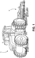
Fig. 1 is a perspective view of an exemplary tractor and implement which may be equipped with an automated guidance system incorporating principles of the invention. -
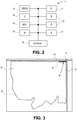
Fig. 2 is a block diagram of certain components of an automated guidance system incorporating principles of the present invention. -
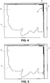
Figs. 3-11 are exemplary screenshots generated by a user interface of the guidance system ofFig. 2 , illustrating the progress of the tractor along a path and suggested waypoints placed on the path by the guidance system. -
Fig. 12 illustrates an exemplary wayline corresponding to two of the waypoints of the path ofFigs. 3-11 . -
Fig. 13 illustrates another exemplary wayline corresponding to two of the waypoints of the path ofFigs. 3-11 . -
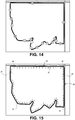
Fig. 14 is an exemplary screenshot similar to those ofFigs. 3-11 , illustrating the path with a plurality of waypoints placed according to another placement scheme. -
Fig. 15 is an exemplary screenshot similar to those ofFigs. 3-11 , illustrating surface elevation values placed along the path. -
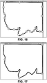
Fig. 16 is an exemplary screenshot similar to the screenshot ofFig. 11 , illustrating a plurality of suggested waypoints placed on the path by the guidance system including a pair of waypoints labeled "H" corresponding to high elevation points and a pair of waypoints labeled "L" corresponding to low elevation points. -
Fig. 17 is an exemplary screenshot similar to the screenshot ofFig. 11 illustrating a plurality of exemplary waypoints placed by the operator as the machine travelled the path. -
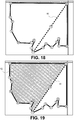
Fig. 18 is an exemplary screenshot similar to the screenshot ofFig. 11 illustrating a wayline corresponding to two of the waypoints placed along the path and a waypoint placed on the wayline. -
Fig. 19 illustrates the screenshot ofFig. 18 including a portion of the field worked by a machine. -
Fig. 20 illustrates the screenshot ofFig. 19 including an additional wayline corresponding to a waypoint on the path and a waypoint on the wayline. -
Fig. 21 is an exemplary screenshot similar to the screenshot ofFig. 11 including a wayline defined by one of the waypoints and a first direction. -
Fig. 22 illustrates the screenshot ofFig. 21 , including the wayline rotated about the waypoint to a second direction. -
Fig. 23 illustrates the screenshot ofFig. 21 , including the wayline rotated about the waypoint to a third direction. -
Fig. 24 illustrates the screenshot ofFig. 23 , including the wayline shifted relative to the original position. - Turning now to the drawing figures, an
exemplary tractor 10 equipped with an automated guidance system incorporating principles of the present invention is illustrated inFig. 1 . The automated guidance system may be used to guide thetractor 10 as the tractor pulls or carries animplement 12 while working a field. While specific reference is made herein to thetractor 10 for purposes of illustration, guidance systems employing principles of the present invention may be used with other machines including, for example, other agricultural machines such as combine harvesters as well as machines used in the other industries, including the construction industry. - The automated guidance system is operable to automatically generate suggested waypoints as the
tractor 10 travels a path associated with a field or other area to be worked by the tractor. The automated guidance system may generate a plurality of suggested waypoints exceeding the number of waypoints needed for automated guidance such that the user may manually select a subset of the waypoints for use in automated guidance. The suggested waypoints are points or locations on the path that may be used by the automated guidance system as points of reference as the tractor works or travels the field, as explained below in greater detail. - Certain components of an exemplary
automated guidance system 14 are illustrated inFig. 2 . Thesystem 14 broadly includes acontroller 16, aposition determining device 18, auser interface 20, one or more sensors 22, one ormore actuators 24, one or more memory/storage components 26, and one or more input/out ports 28. Theposition determining device 18 may be a global navigation satellite system (GNSS) receiver, such as a device configured to receive signals from one or more positioning systems, such as the United States' global positioning system (GPS) and/or the Russian GLONASS system, and to determine a location using the received signals. Theuser interface 20 includes components for receiving instructions or other input from a user and may include buttons, switches, dials, and microphones, as well as components for presenting information or data to users, such as displays, light-emitting diodes, audio speakers and so forth. Theuser interface 20 may include a touchscreen display capable of presenting visual representations of information or data and receiving instructions or input from the user via a single display surface. - The sensors 22 may be associated with any of various components or functions of the
tractor 10 including, for example, various elements of the engine, transmission(s), and hydraulic and electrical systems. Theactuators 24 are configured and placed to drive certain functions of thetractor 10 including, for example, steering when an automated steering function is engaged. Theactuators 24 may take virtually any form but are generally configured to receive control signals or instructions from the controller 16 (or other component of the system 14) and to generate a mechanical movement or action in response to the control signals or instructions. By way of example, the sensors 22 andactuators 24 may be used in automated steering of thetractor 10 wherein the sensors 22 detect a current position of steered wheels and theactuators 24 drive steering movement of the wheels. - The
controller 16 includes one or more integrated circuits programmed or configured to implement the functions described herein. By way of example thecontroller 16 may be a digital controller and may include one or more general purpose microprocessors or microcontrollers, programmable logic devices, or application specific integrated circuits. Thecontroller 16 may include multiple computing components placed in various different locations. Thecontroller 16 may also include one or more discrete and/or analog circuit components operating in conjunction with the one or more integrated circuits or computing components. Furthermore, thecontroller 16 may include or have access to one or more memory elements operable to store executable instructions, data, or both. Thus, the memory/storage device may be built into the same device as the controller or may be external. - It will be appreciated that, for simplicity, certain elements and components of the
system 14 have been omitted from the present discussion and from the drawing ofFig. 2 . A power source or power connector is also associated with theautomated guidance system 14, for example, but is conventional in nature and, therefore, is not discussed herein. In one embodiment, all of the components of theautomated guidance system 14 are contained on or in thetractor 10. The present invention is not so limited, however, and in other embodiments one or more of the components of thesystem 14 may be external to thetractor 10. In another embodiment, for example, some of the components of thesystem 14 are contained on or in thetractor 10 while other components of the system are contained on or in the implement 12. In this embodiment, the components associated with thetractor 10 and the components associated with the implement 12 may communicate via wired or wireless communications according to a local area network such as, for example, a controller area network. Thesystem 14 may be part of a communications and control system conforming to the ISO 11783 (also referred to as "ISOBUS") standard. In yet another exemplary embodiment, one or more components of thesystem 14 may be located remotely from thetractor 10 and the implement 12. In this embodiment, thesystem 14 may include wireless communications components for enabling thetractor 10 to communicate with a remote computer, computer network or system. - The
system 14 is configured to assist a machine operator by helping identify and place waypoints and waylines used as references by thesystem 14 during automated guidance of thetractor 10. Thecontroller 16 may automatically generate the waypoints according to features of the travelled path, according to geographic features of the land associated with the path, according to historic practices, and/or according to other factors. Thecontroller 16 may automatically generated the waypoints to correspond to features of the travelled path, such as turns in the path or predetermined intermediate points on path segments. As used herein, an intermediate point on a path segment is a point or location between endpoints of the path segment, wherein the endpoints of the segment may be determined by turns in the path. A predetermined intermediate point on a path segment may be a particular percentage of the distance from a starting point to an ending point of the path segment, such as 10%, 20%, 30%, 40%, 50%, 60% and so forth. - In a first implementation, the
system 14 automatically generates waypoints associated with path segment endpoints or path corners as thetractor 10 travels along a generally circuitous path defining a work area.Figures 3-11 illustrate an exemplary scenario where this implementation may be used. An operator plans to begin working afield 30 by travelling an intendedpath 32 around thefield 30 to thereby define a working area within thepath 32 or otherwise associated with thepath 32. Initially there may be no visual indicators of the intendedpath 32 and, in fact, thepath 32 may be arbitrarily created as the operator travels along edges of thefield 30adjacent roads 34, around obstacles, and so forth. - The graphical depictions of the
field 30 and guidance elements (e.g., waypoints and waylines) illustrated inFigs. 3-11 (and other figures) may be part of an exemplary graphical display presented to an operator of thetractor 10 via theuser interface 20, such as via a touchscreen. Thus, the graphic display may present a map or depiction of thefield 30 as well as additional geographic or cartographic features of the surrounding area, including roads, streams and ponds. The intendedpath 32 is depicted in these drawings for illustration only and would typically not be presented to the operator via theuser interface 20. As explained above, thepath 32 may be arbitrarily created by the operator. - The operator may begin travelling the intended
path 32 at afirst location 36 illustrated inFig. 3 . Thatlocation 36 may be near an entrance to the field. As thetractor 10 travels the intendedpath 32 from left to right inFig. 3 thesystem 14 tracks the tractor's position and progress, records thepath 38 followed by the tractor, and presents a depiction of thepath 38 as a solid line. When thetractor 10 makes a first turn corresponding to corner 40, thesystem 14 detects the turn and associates a first waypoint, waypoint A, with thecorner 40 defined by the turn, as illustrated inFigs. 4 and 5 . - The
tractor 10 proceeds along asecond path segment 42 from waypoint A toward the bottom ofFigs. 4 and 5 . Thesystem 14 uses position information from theposition determining device 18 to monitor the tractor's position and heading. When thetractor 10 reaches the end of thesegment 42 and turns, as illustrated inFig. 6 , thesystem 14 detects a change in the tractor's heading, identifies a turn, and places a second waypoint-waypoint B-at the intersection of the twosegments Fig. 7 . Thetractor 10 proceeds along thethird segment 44 until the operator makes another turn atcorner 46, as illustrated inFig. 8 , wherein thecontroller 16 detects the turn and places a third waypoint-waypoint C-at the location of theturn 46, as illustrated inFig. 9 . A fourth waypoint, waypoint D, is placed according to the same procedure, as illustrated inFig. 10 . - As the
tractor 10 travels the intendedpath 32, thesystem 14 continues automatically placing waypoints at the various turns or corners of thepath 32 until thetractor 10 completes the path.Figure 11 illustrates the path nearly complete with waypoints A through Q placed on the path. In various embodiments of the invention, thesystem 14 places the waypoints on the path automatically. Thus, as the operator drives thetractor 10 along the path he or she does not need to interact with theuser interface 20 or otherwise take any steps to create the waypoints A through Q. This allows the operator to focus on other aspects of machine operation, including steering, while thesystem 14 places the waypoints. When the operator completes thepath 38 he or she may review the suggested waypoints and select a wayline based on one or more of the suggested waypoints. - The
system 14 may identify corners or turns in thepath 38 as turns corresponding to a radius of curvature that is less than a predetermined turn radius, such as fifty feet, seventy-five feet or one hundred feet. Arcuate portions of thepath 38 with larger radii of curvature may be considered a curved path segment. - The
system 14 presents the waypoints A through Q to the operator as suggested waypoints. In the illustrated embodiment, thesystem 14 presents a graphical depiction of thefield 30, thepath 38 travelled by the tractor, and the plurality of suggested waypoints A-Q via a display associated with theuser interface 20. The intendedpath 32 is depicted in the drawings for illustration only and will typically not be presented to the operator via theuser interface 20, as explained above. Thesystem 14 then receives waypoint information from the user via theuser interface 20, wherein the waypoint information includes waypoints selected by the user for automatic guidance. By way of example, the user may submit waypoint information by physically touching a touchscreen at locations corresponding to the waypoints the user desires to select. Input devices other than touchscreens may be used. - With reference to
Fig. 12 , if the user selects suggested waypoints A and I for automatic guidance, thesystem 14 may respond by generating awayline 48 connecting waypoints A and I. Thewayline 48 may then be used by thesystem 14 for automatic guidance of thetractor 10 as it works thefield 30. Because thesystem 14 generates multiple suggested waypoints, the operator may select any of the waypoints to use for automatic guidance. Rather than selecting waypoints A and I for automatic guidance, for example, the operator may select waypoints D and Q, as illustrated inFig. 13 , wherein thesystem 14 may generate awayline 50 corresponding to those waypoints. - In the implementation illustrated in
Figs. 3-11 thesystem 14 automatically places the suggested waypoints at corners or turns of thepath 38 travelled by thetractor 10. The invention is not so limited and thesystem 14 may place suggested waypoints according to other features of the travelledpath 38. In another exemplary implementation, thesystem 14 automatically places the suggested waypoints at intermediate points along the path segments rather than at corners or segment endpoints. Thesystem 14 may place the waypoints at segment midpoints, for example, as illustrated inFig. 14 . Thesystem 14 may place the suggested waypoints at any intermediate point of the various path segments, wherein the intermediate point may corresponding to a percentage of the distance from a first end of each segment to another, as explained above. - In other situations it may be desirable to place the suggested waypoints according to path features unrelated to path segments. A substantially arcuate outer boundary of a field, for example, may not have segments easily defined by corners or endpoints. In such a situation the
system 14 may place the suggested waypoints at locations associated with, for example, a total distance travelled by thetractor 10, wherein thesystem 14 automatically places waypoints along the path at predetermined total travel distance intervals, such as one hundred yards or two hundred yards, or fractions of the total distance of the travelled path calculated once the path is completed by thetractor 10. Alternatively, thesystem 14 may place the suggested waypoints according to the orientation of thetractor 10 relative to a cardinal direction, such as north. These are but a few examples. - In other embodiments of the invention, the
system 14 places the suggested waypoints according to schemes unrelated to features or characteristics of the path itself. By way of example, such schemes may relate to geographic features of the land surrounding and/or associated with the path, historic practices or trends, or other factors. - An exemplary geographic feature of the land that may be used by the system to place suggested waypoints is surface elevation. It may be desirable, for example, to set the automatic guidance features of the invention to guide the
tractor 10 to work thefield 30 according to an inclination of the field surface, which may be estimated using the surface elevation of thefield 30. With reference toFig. 15 , as thetractor 10 travels thepath 38 thesystem 14 collects elevation data, associates elevation data with each location of thetractor 10, and stores the elevation data. - If the
tractor 10 begins travelling thepath 38 atlocation 50, for example, thesystem 14 may assign an initial elevation value of "0" to that location regardless of the actual surface elevation-thus, the elevation value may be a relative value unrelated to actual elevation. As thetractor 10 travels along thepath 38 from thelocation 50 toward thecorner 40 inFig. 15 , the surface elevation of thefield 30 increases and thesystem 14 assigns an elevation value of "1" and then "2" as thetractor 10 approaches thecorner 40. At thecorner 40 the elevation has increased to "3." Each of the elevation values may correspond to a difference in elevation between a current location and thelocation 50 and may be expressed as a number of feet or number of meters. As thetractor 10 continues travelling thepath 38 thesystem 14 assigns elevation values to points along the path, detecting changes in elevation and assigning elevation values accordingly. - It can be seen from
Fig. 15 that the highest points of elevation along the path correspond approximately tolocations system 14 may automatically generate a pair of suggested waypoints corresponding tolocations path 38. The system may also automatically generate a pair of suggested waypoints corresponding tolocations 56 and 58, and label those waypoints "L" to indicate to the operator that those waypoints correspond to the lowest points of elevation of the path. The waypoints labeled "H" and "L" may be presented to the operator along with other waypoints, as illustrated inFig. 16 . - The operator may select the waypoints labeled "H" for a wayline that corresponds to the highest elevation of the field, or may select the waypoints labeled "L" for a wayline that connects the lowest points of the field on opposite sides of a ridge. Assuming that a straight
line intersecting locations wayline intersecting locations 56 and 58 would allow thetractor 10 to work thefield 30 along lines that are perpendicular to the ridge. The operator's preference for one of the two waylines (or an entirely different wayline) may depend on the operation being performed and the type of machine used to perform the operation. In the two above examples, the operator intends to work the field along paths that are parallel with or perpendicular to a direction of changing elevation of a surface of thefield 30. The operator may desire to use the elevation information in other ways when selecting waypoints. - In an embodiment outside of the scope of the invention, the operator manually places waypoints as the
tractor 10 travels along thepath 38. The operator may manually drive thepath 38 and indicate positions of various waypoints along the path via theuser interface 20 by, for example, pressing a button, engaging a touchscreen or making an audible sound detected by a microphone. An exemplary scenario of this embodiment is illustrated graphically inFig. 17 , wherein the operator selected waypoints A through E while travelling along thepath 38. Using this embodiment, the user may identify a plurality of initial waypoints while travelling thepath 38 and select one or more of the initial waypoints for use in automated guidance. A user may select, for example, any two of the initial waypoints A-E to define a wayline. - With reference now to
Fig. 18 , once awayline 60 is created according to any of the methods discussed herein, a waypoint may be placed on thewayline 60 either automatically by thesystem 14 or manually by the operator. Waypoint R, for example, may be placed automatically by thesystem 14 at any time after thewayline 60 is created, or may be placed manually by the operator. Thesystem 14 may automatically place waypoint R at the midpoint of the wayline 60 (or any other intermediate point of the wayline) and then adjust a location of the waypoint in response to user input received via theuser interface 20. - The operator may use the waypoint R to generate a second wayline. The operator may choose to work a
first portion 62 of the field using only thefirst wayline 60, as illustrated inFig. 19 , then create asecond wayline 64 corresponding to waypoints R and D to work a second portion of thefield 66, as illustrated inFig. 20 . - The operator may select two waypoints to define a wayline, as explained above, or may select a single waypoint to define a wayline. In the latter scenario, the operator may select a single waypoint and then select an angle or orientation of a wayline intersecting the waypoint. With reference to
Fig. 21 , if the operator selects suggested waypoint K, thesystem 14 may generate awayline 68 that intersects waypoint K and then present a graphical representation of thewayline 68 via theuser interface 20. The generatedwayline 68 may simply be parallel with one of the cardinal directions, such as north. The operator may then adjust an angle of thewayline 68 via theuser interface 20. Thewayline 68 is illustrated rotated counterclockwise inFig. 22 and clockwise inFig. 23 . By way of example, the operator may adjust thewayline 68 by pressing a tactile or virtual button, rolling a dial, or "dragging" the wayline on a touchscreen by touching the screen and moving a finger across the touchscreen. - Regardless of whether the operator selects two waypoints to define the wayline or a single waypoint, the operator may adjust the angle of the wayline. Similarly, in ether scenario the operator may adjust a position of the wayline by moving the wayline side to side or up and down without rotating the wayline. As illustrated in
Fig. 24 , a wayline that initially intersected waypoint K may be moved to the left. Thus, by rotating and moving a wayline left, right, up and down the operator may reposition the wayline to any position in the field. Furthermore, a primary wayline, secondary wayline or both may be so adjusted. - In other embodiments of the invention, the
system 14 may receive or retrieve data defining a boundary of the field or area to be worked, thereby relieving the operator of the need to travel a path defining an area to be worked before working the area. This may be desirable where the operator wishes to work the perimeter of the field last, such as in tillage operators that render the surface rough and the operator wishes to work the headland last so that the headland surface is smooth during headland maneuvering. Rather than driving thepath 38, for example, the operator may direct thesystem 14 to retrieve data defining thepath 38. Once thepath 38 is defined by thesystem 14, waypoints and waylines may be suggested, selected and/or adjusted substantially as explained above. As used herein, thesystem 14 is configured to receive boundary information if thesystem 14 is configured to retrieve the boundary information from a memory or storage device, if thesystem 14 is configured to receive the information from one of the input/output port, or if thesystem 14 is configured to receive the boundary information from another computing device via a network.
Claims (19)
- A guidance system (14) for a mobile machine (10), the system comprising:a location determining device (18) for determining a location of the machine;a user interface (20) including a display; anda controller (16) configured to -receive location information from the location determining device (18),detect a path (38) followed by the machine (10) using the location information,present to a user via the user interface (20), a visual representation of the path (38), andautomatically guide the machine (10) in response to information received from the user via the user interface,characterised in that the controller (16) is further configured to automatically generate a plurality of preliminary waypoints (A-Q) corresponding to different locations on the path (38) and indicate the same as points in the visual representation, wherein the information received from the user via the user interface (20) comprises an indication of one or more selected waypoints corresponding to one or more of the preliminary waypoints (A-Q).
- The guidance system as set forth in claim 1, the controller (16) configured to automatically generate the plurality of preliminary waypoints (A-Q) and present the suggested waypoints to the user as the machine travels the path (38).
- The guidance system as set forth in claim 1, the controller (16) configured to automatically generate the preliminary waypoints (A-Q) to correspond to features of the path (38).
- The guidance system as set forth in claim 3, the controller (16) configured to automatically generate the preliminary waypoints (A-Q) such that each waypoint corresponds to a turn in the path (38).
- The guidance system as set forth in claim 4, the controller (16) configured to automatically generate the preliminary waypoints (A-Q) such that each waypoint corresponds to a turn in the path (38) defined by a turn radius less than a predetermined turn radius.
- The guidance system as set forth in claim 2, the controller (16) configured to automatically generate the preliminary waypoints (A-Q) such that the waypoints correspond to predetermined intermediate points of path segments, each path segment being a portion of the path (38) between consecutive turns.
- The guidance system as set forth in claim 1, the controller (16) configured to automatically generate the preliminary waypoints (A-Q) according to historical information relating to guidance patterns used to work the field (30) previously.
- The guidance system as set forth in claim 1, the user interface (20) including a touchscreen and configured to -
present the visual representation of the path (38) on the touchscreen, and
receive the waypoint information from the user as the user touches the suggested waypoints on the touchscreen. - The guidance system as set forth in claim 1, the controller (16) configured to simultaneously adjust the position of all of the waypoints (A-Q) in response to receiving a user input via the user interface (20).
- The guidance system as set forth in claim 1, the controller (16) further configured to allow the user to adjust a selected waypoint by changing a location of the waypoint.
- The guidance system as set forth in claim 1, the controller (16) configured to automatically guide the machine (10) according to the one or more selected waypoints by generating a wayline corresponding to the one or more selected waypoints and guiding the machine along paths that are parallel with the wayline.
- The guidance system as set forth in claim 11, the controller (16) configured to receive wayline adjustment information from the user via the user interface (20) and adjust the wayline according to the wayline adjustment information.
- The guidance system as set forth in claim 1, the controller (16) configured to automatically generate the preliminary waypoints (A-Q) according to geographic features of land associated with the path (38).
- The guidance system as set forth in claim 13, the geographic features including surface elevation features.
- The guidance system as set forth in claim 1, the controller (16) configured to -
generate a first wayline corresponding to the one or more selected waypoints,
automatically generate a waypoint on the first wayline, and
automatically guide the machine using at least the waypoint on the first wayline. - The guidance system as set forth in claim 15, the controller (16) configured to - ge
nerate a second wayline corresponding to the waypoint on the first wayline and at least one of the suggested waypoints, and
automatically guide the machine (10) using the second wayline. - An agricultural vehicle (10) comprising a guidance system (14) as claimed in any preceding claim, wherein the plurality of preliminary waypoints (A-Q) are suggested waypoints associated with the path and the received waypoint information from the user indicates two of the suggested waypoints as selected waypoints.
- The agricultural vehicle (10) as set forth in claim 17, the display being a touchscreen display and the controller (16) configured to receive the way point information from the user via the touchscreen.
- A guidance system (14) for an agricultural machine (10), the system comprising:a location determining device (18) for determining a location of the machine;a user interface (20) including a display; anda controller (16) configured to -characterised in that the controller (16) is further configured to automatically generate a plurality of preliminary waypoints (A-Q) corresponding to different locations on the boundary and indicate the same as points in the visual representation, wherein the information received from the user via the user interface (20) comprises an indication of one or more selected waypoints corresponding to one or more of the preliminary waypoints (A-Q).receive boundary information, the boundary information indicating a boundary of an area (30) to be worked by the agricultural machine,present to a user, via the user interface (20), a visual representation of the area (30); andautomatically guide the machine (10) in response to information received from the user via the user interface (20),
Applications Claiming Priority (3)
| Application Number | Priority Date | Filing Date | Title |
|---|---|---|---|
| US201361905525P | 2013-11-18 | 2013-11-18 | |
| US201361905892P | 2013-11-19 | 2013-11-19 | |
| PCT/US2014/065733 WO2015073844A1 (en) | 2013-11-18 | 2014-11-14 | System and method for automatically generating vehicle guidance waypoints and waylines |
Publications (2)
| Publication Number | Publication Date |
|---|---|
| EP3072025A1 EP3072025A1 (en) | 2016-09-28 |
| EP3072025B1 true EP3072025B1 (en) | 2020-01-22 |
Family
ID=52021428
Family Applications (1)
| Application Number | Title | Priority Date | Filing Date |
|---|---|---|---|
| EP14810062.1A Active EP3072025B1 (en) | 2013-11-18 | 2014-11-14 | System and method for automatically generating vehicle guidance waypoints and waylines |
Country Status (3)
| Country | Link |
|---|---|
| US (3) | US9303998B2 (en) |
| EP (1) | EP3072025B1 (en) |
| WO (1) | WO2015073844A1 (en) |
Cited By (1)
| Publication number | Priority date | Publication date | Assignee | Title |
|---|---|---|---|---|
| DE102023115941A1 (en) | 2023-06-19 | 2024-12-19 | Claas E-Systems Gmbh | Work machine with touch-sensitive route adjustment |
Families Citing this family (24)
| Publication number | Priority date | Publication date | Assignee | Title |
|---|---|---|---|---|
| US20150348419A1 (en) * | 2012-12-28 | 2015-12-03 | Agco Corporation | Method of assigning planned paths to multiple machines to cooperatively cover area |
| US9303998B2 (en) * | 2013-11-18 | 2016-04-05 | Agco Corporation | System and method for automatically generating vehicle guidance waypoints and waylines |
| US9821847B2 (en) * | 2015-11-24 | 2017-11-21 | Deere & Company | Method for guiding an off-road vehicle along a curved path |
| EP3633481A1 (en) * | 2016-03-09 | 2020-04-08 | Yanmar Co., Ltd. | Work vehicle |
| US10194574B2 (en) * | 2016-11-18 | 2019-02-05 | Cnh Industrial America Llc | System for adjusting smoothing tools of a harrow according to location |
| US11096323B2 (en) * | 2017-04-18 | 2021-08-24 | CropZilla Software, Inc. | Machine control system providing actionable management information and insight using agricultural telematics |
| JP2019004853A (en) * | 2017-06-28 | 2019-01-17 | 株式会社クボタ | Work vehicle |
| US11029168B2 (en) * | 2017-10-10 | 2021-06-08 | The Government Of The United States Of America, As Represented By The Secretary Of The Navy | Method for identifying optimal vehicle paths when energy is a key metric or constraint |
| DE102017123592A1 (en) * | 2017-10-11 | 2019-04-11 | Amazonen-Werke H. Dreyer Gmbh & Co. Kg | Agricultural machine |
| WO2019104581A1 (en) * | 2017-11-30 | 2019-06-06 | 深圳市大疆创新科技有限公司 | Track generating method and apparatus, and unmanned ground vehicle |
| US11277956B2 (en) * | 2018-07-26 | 2022-03-22 | Bear Flag Robotics, Inc. | Vehicle controllers for agricultural and industrial applications |
| US11800827B2 (en) | 2018-09-14 | 2023-10-31 | Agjunction Llc | Using non-real-time computers for agricultural guidance systems |
| KR102626835B1 (en) | 2018-10-08 | 2024-01-18 | 삼성전자주식회사 | Method and apparatus of determining path |
| JP7036707B2 (en) * | 2018-12-14 | 2022-03-15 | ヤンマーパワーテクノロジー株式会社 | Travel route generator |
| EP3841861A3 (en) * | 2019-12-27 | 2021-10-06 | Kubota Corporation | Work support system and work support device positioned in an area |
| US12016257B2 (en) | 2020-02-19 | 2024-06-25 | Sabanto, Inc. | Methods for detecting and clearing debris from planter gauge wheels, closing wheels and seed tubes |
| US12461083B2 (en) | 2020-08-03 | 2025-11-04 | Sabanto, Inc. | Methods for improved agricultural procedures |
| JP7485586B2 (en) * | 2020-11-12 | 2024-05-16 | ヤンマーホールディングス株式会社 | Work area setting system, work area setting method, and work area setting program |
| US11914379B2 (en) | 2020-12-23 | 2024-02-27 | Deere & Company | Methods and apparatus to generate a path plan |
| US12144275B2 (en) | 2021-08-31 | 2024-11-19 | Deere & Company | Methods, apparatus, and articles of manufacture to generate a turn path for a vehicle |
| US12591243B2 (en) * | 2022-02-07 | 2026-03-31 | Doosan Bobcat North America, Inc. | Path determination for automatic mowers |
| GB202202445D0 (en) | 2022-02-23 | 2022-04-06 | Agco Int Gmbh | Operational path planning |
| JP2024047235A (en) * | 2022-09-26 | 2024-04-05 | 三菱重工業株式会社 | Route setting method, program and mobile device |
| US12495725B2 (en) * | 2023-09-15 | 2025-12-16 | Kubota Corporation | Systems and methods for work vehicles |
Family Cites Families (19)
| Publication number | Priority date | Publication date | Assignee | Title |
|---|---|---|---|---|
| US6088644A (en) | 1998-08-12 | 2000-07-11 | Caterpillar Inc. | Method and apparatus for determining a path to be traversed by a mobile machine |
| US6236924B1 (en) * | 1999-06-21 | 2001-05-22 | Caterpillar Inc. | System and method for planning the operations of an agricultural machine in a field |
| US8145390B2 (en) * | 2007-04-26 | 2012-03-27 | Cnh America Llc | Swath finder feature integrated with multipurpose display |
| US8515626B2 (en) | 2008-07-22 | 2013-08-20 | Trimble Navigation Limited | System and method for machine guidance control |
| US8649930B2 (en) * | 2009-09-17 | 2014-02-11 | Agjunction Llc | GNSS integrated multi-sensor control system and method |
| US20110160994A1 (en) | 2009-12-29 | 2011-06-30 | Agco Corporation | Auto-detection of a field in fleet management |
| US8583326B2 (en) * | 2010-02-09 | 2013-11-12 | Agjunction Llc | GNSS contour guidance path selection |
| EP3259972B1 (en) * | 2012-07-25 | 2021-12-08 | Precision Planting LLC | System and method for multi-row agricultural implement control and monitoring |
| EP3018987B1 (en) * | 2013-07-10 | 2020-09-02 | Agco Corporation | Automating distribution of work in a field |
| US20160360697A1 (en) * | 2013-09-03 | 2016-12-15 | Agco Corporation | System and method for automatically changing machine control state |
| US9303998B2 (en) * | 2013-11-18 | 2016-04-05 | Agco Corporation | System and method for automatically generating vehicle guidance waypoints and waylines |
| EP2980669B1 (en) * | 2014-08-01 | 2017-09-20 | AGCO Corporation | Determining field characterisitics using optical recognition |
| US9760094B2 (en) * | 2014-10-08 | 2017-09-12 | The Boeing Company | Distributed collaborative operations processor systems and methods |
| US10088842B2 (en) * | 2015-03-30 | 2018-10-02 | Agco Corporation | Isobus wireless networking of agricultural machines in a collaborative agricultural process |
| US9964648B2 (en) * | 2015-06-16 | 2018-05-08 | Insero LLC | Guidiance system and method based on dead reckoning positioning and heading augmented by GNSS and predictive path selection |
| EP3139237B1 (en) * | 2015-09-01 | 2020-01-29 | AGCO Corporation | Machine-to-machine sharing of wayline deviation information |
| US20170088147A1 (en) * | 2015-09-30 | 2017-03-30 | Agco Corporation | User Interface for Mobile Machines |
| US20170090741A1 (en) * | 2015-09-30 | 2017-03-30 | Agco Corporation | User Interface for Mobile Machines |
| EP3203341A1 (en) * | 2016-02-08 | 2017-08-09 | AGCO Corporation | Curved wayline extensions for contour path planning |
-
2014
- 2014-11-14 US US14/541,989 patent/US9303998B2/en not_active Expired - Fee Related
- 2014-11-14 US US15/033,849 patent/US10194575B2/en active Active
- 2014-11-14 EP EP14810062.1A patent/EP3072025B1/en active Active
- 2014-11-14 WO PCT/US2014/065733 patent/WO2015073844A1/en not_active Ceased
-
2016
- 2016-03-23 US US15/078,554 patent/US20170071122A1/en not_active Abandoned
Non-Patent Citations (1)
| Title |
|---|
| None * |
Cited By (1)
| Publication number | Priority date | Publication date | Assignee | Title |
|---|---|---|---|---|
| DE102023115941A1 (en) | 2023-06-19 | 2024-12-19 | Claas E-Systems Gmbh | Work machine with touch-sensitive route adjustment |
Also Published As
| Publication number | Publication date |
|---|---|
| US20150142308A1 (en) | 2015-05-21 |
| US20160274587A1 (en) | 2016-09-22 |
| US20170071122A1 (en) | 2017-03-16 |
| US10194575B2 (en) | 2019-02-05 |
| US9303998B2 (en) | 2016-04-05 |
| EP3072025A1 (en) | 2016-09-28 |
| WO2015073844A1 (en) | 2015-05-21 |
Similar Documents
| Publication | Publication Date | Title |
|---|---|---|
| US10194575B2 (en) | System and method for automatically generating vehicle guidance waypoints and waylines | |
| US10386844B2 (en) | System and method for using geo-fenced guidance lines | |
| JP7209783B2 (en) | Driving route generation device and driving route generation program | |
| JP5667731B1 (en) | Field guidance system, field guidance method, software, and storage medium storing software | |
| US11112505B2 (en) | Navigation for a robotic work tool | |
| JP6031491B2 (en) | Field guidance system, field guidance method, software, and storage medium storing software | |
| JP7714382B2 (en) | Route determination method, route determination system, and route determination program | |
| EP3834601A1 (en) | Harvester, harvesting system, harvesting method, harvesting program and recording medium | |
| EP3300562A1 (en) | System and method for guided line acquisitions | |
| JP7113708B2 (en) | field work vehicle | |
| JP2017060524A (en) | Field guidance system and field guidance method as well as software and storage medium with software stored therein | |
| JP6857267B2 (en) | Field guidance system, field guidance method, software and storage medium containing software | |
| AU2023201850B2 (en) | Method for determining information, remote terminal, and mower | |
| JP2018004589A (en) | Route retrieval program, route retrieval system, and work vehicle having route retrieval system incorporated | |
| AU2018244578A2 (en) | Warehouse mapping tools | |
| TW202116144A (en) | Method and module for displacement processing and mower device | |
| CN109074038A (en) | agricultural machine control method, device and agricultural machine | |
| KR20230009519A (en) | Work vehicle and travel region specification device | |
| JP6088104B2 (en) | Field guidance system, field guidance method, software, and storage medium storing software | |
| JP2016189172A (en) | Automated driving information management system | |
| WO2017106478A1 (en) | Path planning with field attribute information | |
| JP2025159054A (en) | Autonomous driving method, automatic driving system, and work vehicle | |
| US20230251669A1 (en) | Path determination for automatic mowers | |
| JP2018139604A (en) | Field guidance system and field guidance method, and software and recording medium having software stored therein | |
| JP7837923B2 (en) | Automated driving method, automated driving program, automated driving system, and work vehicle |
Legal Events
| Date | Code | Title | Description |
|---|---|---|---|
| PUAI | Public reference made under article 153(3) epc to a published international application that has entered the european phase |
Free format text: ORIGINAL CODE: 0009012 |
|
| 17P | Request for examination filed |
Effective date: 20160620 |
|
| AK | Designated contracting states |
Kind code of ref document: A1 Designated state(s): AL AT BE BG CH CY CZ DE DK EE ES FI FR GB GR HR HU IE IS IT LI LT LU LV MC MK MT NL NO PL PT RO RS SE SI SK SM TR |
|
| AX | Request for extension of the european patent |
Extension state: BA ME |
|
| DAX | Request for extension of the european patent (deleted) | ||
| REG | Reference to a national code |
Ref country code: DE Ref legal event code: R079 Ref document number: 602014060405 Country of ref document: DE Free format text: PREVIOUS MAIN CLASS: G05D0001020000 Ipc: G06F0003048800 |
|
| RIC1 | Information provided on ipc code assigned before grant |
Ipc: G01C 21/00 20060101ALI20190619BHEP Ipc: B62D 49/06 20060101ALI20190619BHEP Ipc: G05D 1/02 20060101ALI20190619BHEP Ipc: G06F 3/0488 20130101AFI20190619BHEP Ipc: G01C 21/36 20060101ALI20190619BHEP Ipc: A01B 69/04 20060101ALI20190619BHEP Ipc: G01C 21/34 20060101ALI20190619BHEP Ipc: G06F 3/0482 20130101ALI20190619BHEP Ipc: B60K 35/00 20060101ALI20190619BHEP |
|
| GRAP | Despatch of communication of intention to grant a patent |
Free format text: ORIGINAL CODE: EPIDOSNIGR1 |
|
| STAA | Information on the status of an ep patent application or granted ep patent |
Free format text: STATUS: GRANT OF PATENT IS INTENDED |
|
| INTG | Intention to grant announced |
Effective date: 20190910 |
|
| GRAS | Grant fee paid |
Free format text: ORIGINAL CODE: EPIDOSNIGR3 |
|
| GRAA | (expected) grant |
Free format text: ORIGINAL CODE: 0009210 |
|
| STAA | Information on the status of an ep patent application or granted ep patent |
Free format text: STATUS: THE PATENT HAS BEEN GRANTED |
|
| AK | Designated contracting states |
Kind code of ref document: B1 Designated state(s): AL AT BE BG CH CY CZ DE DK EE ES FI FR GB GR HR HU IE IS IT LI LT LU LV MC MK MT NL NO PL PT RO RS SE SI SK SM TR |
|
| REG | Reference to a national code |
Ref country code: GB Ref legal event code: FG4D |
|
| REG | Reference to a national code |
Ref country code: CH Ref legal event code: EP |
|
| REG | Reference to a national code |
Ref country code: AT Ref legal event code: REF Ref document number: 1227346 Country of ref document: AT Kind code of ref document: T Effective date: 20200215 |
|
| REG | Reference to a national code |
Ref country code: IE Ref legal event code: FG4D |
|
| REG | Reference to a national code |
Ref country code: DE Ref legal event code: R096 Ref document number: 602014060405 Country of ref document: DE |
|
| REG | Reference to a national code |
Ref country code: NL Ref legal event code: MP Effective date: 20200122 |
|
| REG | Reference to a national code |
Ref country code: LT Ref legal event code: MG4D |
|
| PG25 | Lapsed in a contracting state [announced via postgrant information from national office to epo] |
Ref country code: NO Free format text: LAPSE BECAUSE OF FAILURE TO SUBMIT A TRANSLATION OF THE DESCRIPTION OR TO PAY THE FEE WITHIN THE PRESCRIBED TIME-LIMIT Effective date: 20200422 Ref country code: PT Free format text: LAPSE BECAUSE OF FAILURE TO SUBMIT A TRANSLATION OF THE DESCRIPTION OR TO PAY THE FEE WITHIN THE PRESCRIBED TIME-LIMIT Effective date: 20200614 Ref country code: FI Free format text: LAPSE BECAUSE OF FAILURE TO SUBMIT A TRANSLATION OF THE DESCRIPTION OR TO PAY THE FEE WITHIN THE PRESCRIBED TIME-LIMIT Effective date: 20200122 Ref country code: RS Free format text: LAPSE BECAUSE OF FAILURE TO SUBMIT A TRANSLATION OF THE DESCRIPTION OR TO PAY THE FEE WITHIN THE PRESCRIBED TIME-LIMIT Effective date: 20200122 Ref country code: NL Free format text: LAPSE BECAUSE OF FAILURE TO SUBMIT A TRANSLATION OF THE DESCRIPTION OR TO PAY THE FEE WITHIN THE PRESCRIBED TIME-LIMIT Effective date: 20200122 |
|
| PG25 | Lapsed in a contracting state [announced via postgrant information from national office to epo] |
Ref country code: GR Free format text: LAPSE BECAUSE OF FAILURE TO SUBMIT A TRANSLATION OF THE DESCRIPTION OR TO PAY THE FEE WITHIN THE PRESCRIBED TIME-LIMIT Effective date: 20200423 Ref country code: SE Free format text: LAPSE BECAUSE OF FAILURE TO SUBMIT A TRANSLATION OF THE DESCRIPTION OR TO PAY THE FEE WITHIN THE PRESCRIBED TIME-LIMIT Effective date: 20200122 Ref country code: BG Free format text: LAPSE BECAUSE OF FAILURE TO SUBMIT A TRANSLATION OF THE DESCRIPTION OR TO PAY THE FEE WITHIN THE PRESCRIBED TIME-LIMIT Effective date: 20200422 Ref country code: IS Free format text: LAPSE BECAUSE OF FAILURE TO SUBMIT A TRANSLATION OF THE DESCRIPTION OR TO PAY THE FEE WITHIN THE PRESCRIBED TIME-LIMIT Effective date: 20200522 Ref country code: LV Free format text: LAPSE BECAUSE OF FAILURE TO SUBMIT A TRANSLATION OF THE DESCRIPTION OR TO PAY THE FEE WITHIN THE PRESCRIBED TIME-LIMIT Effective date: 20200122 Ref country code: HR Free format text: LAPSE BECAUSE OF FAILURE TO SUBMIT A TRANSLATION OF THE DESCRIPTION OR TO PAY THE FEE WITHIN THE PRESCRIBED TIME-LIMIT Effective date: 20200122 |
|
| REG | Reference to a national code |
Ref country code: DE Ref legal event code: R097 Ref document number: 602014060405 Country of ref document: DE |
|
| PG25 | Lapsed in a contracting state [announced via postgrant information from national office to epo] |
Ref country code: SK Free format text: LAPSE BECAUSE OF FAILURE TO SUBMIT A TRANSLATION OF THE DESCRIPTION OR TO PAY THE FEE WITHIN THE PRESCRIBED TIME-LIMIT Effective date: 20200122 Ref country code: LT Free format text: LAPSE BECAUSE OF FAILURE TO SUBMIT A TRANSLATION OF THE DESCRIPTION OR TO PAY THE FEE WITHIN THE PRESCRIBED TIME-LIMIT Effective date: 20200122 Ref country code: EE Free format text: LAPSE BECAUSE OF FAILURE TO SUBMIT A TRANSLATION OF THE DESCRIPTION OR TO PAY THE FEE WITHIN THE PRESCRIBED TIME-LIMIT Effective date: 20200122 Ref country code: DK Free format text: LAPSE BECAUSE OF FAILURE TO SUBMIT A TRANSLATION OF THE DESCRIPTION OR TO PAY THE FEE WITHIN THE PRESCRIBED TIME-LIMIT Effective date: 20200122 Ref country code: SM Free format text: LAPSE BECAUSE OF FAILURE TO SUBMIT A TRANSLATION OF THE DESCRIPTION OR TO PAY THE FEE WITHIN THE PRESCRIBED TIME-LIMIT Effective date: 20200122 Ref country code: ES Free format text: LAPSE BECAUSE OF FAILURE TO SUBMIT A TRANSLATION OF THE DESCRIPTION OR TO PAY THE FEE WITHIN THE PRESCRIBED TIME-LIMIT Effective date: 20200122 Ref country code: RO Free format text: LAPSE BECAUSE OF FAILURE TO SUBMIT A TRANSLATION OF THE DESCRIPTION OR TO PAY THE FEE WITHIN THE PRESCRIBED TIME-LIMIT Effective date: 20200122 Ref country code: CZ Free format text: LAPSE BECAUSE OF FAILURE TO SUBMIT A TRANSLATION OF THE DESCRIPTION OR TO PAY THE FEE WITHIN THE PRESCRIBED TIME-LIMIT Effective date: 20200122 |
|
| REG | Reference to a national code |
Ref country code: AT Ref legal event code: MK05 Ref document number: 1227346 Country of ref document: AT Kind code of ref document: T Effective date: 20200122 |
|
| PLBE | No opposition filed within time limit |
Free format text: ORIGINAL CODE: 0009261 |
|
| STAA | Information on the status of an ep patent application or granted ep patent |
Free format text: STATUS: NO OPPOSITION FILED WITHIN TIME LIMIT |
|
| 26N | No opposition filed |
Effective date: 20201023 |
|
| PG25 | Lapsed in a contracting state [announced via postgrant information from national office to epo] |
Ref country code: AT Free format text: LAPSE BECAUSE OF FAILURE TO SUBMIT A TRANSLATION OF THE DESCRIPTION OR TO PAY THE FEE WITHIN THE PRESCRIBED TIME-LIMIT Effective date: 20200122 |
|
| PG25 | Lapsed in a contracting state [announced via postgrant information from national office to epo] |
Ref country code: PL Free format text: LAPSE BECAUSE OF FAILURE TO SUBMIT A TRANSLATION OF THE DESCRIPTION OR TO PAY THE FEE WITHIN THE PRESCRIBED TIME-LIMIT Effective date: 20200122 Ref country code: SI Free format text: LAPSE BECAUSE OF FAILURE TO SUBMIT A TRANSLATION OF THE DESCRIPTION OR TO PAY THE FEE WITHIN THE PRESCRIBED TIME-LIMIT Effective date: 20200122 |
|
| PG25 | Lapsed in a contracting state [announced via postgrant information from national office to epo] |
Ref country code: MC Free format text: LAPSE BECAUSE OF FAILURE TO SUBMIT A TRANSLATION OF THE DESCRIPTION OR TO PAY THE FEE WITHIN THE PRESCRIBED TIME-LIMIT Effective date: 20200122 |
|
| REG | Reference to a national code |
Ref country code: CH Ref legal event code: PL |
|
| PG25 | Lapsed in a contracting state [announced via postgrant information from national office to epo] |
Ref country code: LU Free format text: LAPSE BECAUSE OF NON-PAYMENT OF DUE FEES Effective date: 20201114 |
|
| PG25 | Lapsed in a contracting state [announced via postgrant information from national office to epo] |
Ref country code: LI Free format text: LAPSE BECAUSE OF NON-PAYMENT OF DUE FEES Effective date: 20201130 Ref country code: CH Free format text: LAPSE BECAUSE OF NON-PAYMENT OF DUE FEES Effective date: 20201130 |
|
| PG25 | Lapsed in a contracting state [announced via postgrant information from national office to epo] |
Ref country code: IE Free format text: LAPSE BECAUSE OF NON-PAYMENT OF DUE FEES Effective date: 20201114 |
|
| PG25 | Lapsed in a contracting state [announced via postgrant information from national office to epo] |
Ref country code: TR Free format text: LAPSE BECAUSE OF FAILURE TO SUBMIT A TRANSLATION OF THE DESCRIPTION OR TO PAY THE FEE WITHIN THE PRESCRIBED TIME-LIMIT Effective date: 20200122 Ref country code: MT Free format text: LAPSE BECAUSE OF FAILURE TO SUBMIT A TRANSLATION OF THE DESCRIPTION OR TO PAY THE FEE WITHIN THE PRESCRIBED TIME-LIMIT Effective date: 20200122 Ref country code: CY Free format text: LAPSE BECAUSE OF FAILURE TO SUBMIT A TRANSLATION OF THE DESCRIPTION OR TO PAY THE FEE WITHIN THE PRESCRIBED TIME-LIMIT Effective date: 20200122 |
|
| PG25 | Lapsed in a contracting state [announced via postgrant information from national office to epo] |
Ref country code: MK Free format text: LAPSE BECAUSE OF FAILURE TO SUBMIT A TRANSLATION OF THE DESCRIPTION OR TO PAY THE FEE WITHIN THE PRESCRIBED TIME-LIMIT Effective date: 20200122 Ref country code: AL Free format text: LAPSE BECAUSE OF FAILURE TO SUBMIT A TRANSLATION OF THE DESCRIPTION OR TO PAY THE FEE WITHIN THE PRESCRIBED TIME-LIMIT Effective date: 20200122 |
|
| PGFP | Annual fee paid to national office [announced via postgrant information from national office to epo] |
Ref country code: IT Payment date: 20221121 Year of fee payment: 9 |
|
| PGFP | Annual fee paid to national office [announced via postgrant information from national office to epo] |
Ref country code: BE Payment date: 20221118 Year of fee payment: 9 |
|
| P01 | Opt-out of the competence of the unified patent court (upc) registered |
Effective date: 20230518 |
|
| PGFP | Annual fee paid to national office [announced via postgrant information from national office to epo] |
Ref country code: GB Payment date: 20231123 Year of fee payment: 10 |
|
| REG | Reference to a national code |
Ref country code: BE Ref legal event code: MM Effective date: 20231130 |
|
| PG25 | Lapsed in a contracting state [announced via postgrant information from national office to epo] |
Ref country code: BE Free format text: LAPSE BECAUSE OF NON-PAYMENT OF DUE FEES Effective date: 20231130 |
|
| PG25 | Lapsed in a contracting state [announced via postgrant information from national office to epo] |
Ref country code: BE Free format text: LAPSE BECAUSE OF NON-PAYMENT OF DUE FEES Effective date: 20231130 |
|
| PG25 | Lapsed in a contracting state [announced via postgrant information from national office to epo] |
Ref country code: IT Free format text: LAPSE BECAUSE OF NON-PAYMENT OF DUE FEES Effective date: 20231114 |
|
| PG25 | Lapsed in a contracting state [announced via postgrant information from national office to epo] |
Ref country code: IT Free format text: LAPSE BECAUSE OF NON-PAYMENT OF DUE FEES Effective date: 20231114 |
|
| GBPC | Gb: european patent ceased through non-payment of renewal fee |
Effective date: 20241114 |
|
| PG25 | Lapsed in a contracting state [announced via postgrant information from national office to epo] |
Ref country code: GB Free format text: LAPSE BECAUSE OF NON-PAYMENT OF DUE FEES Effective date: 20241114 |
|
| PGFP | Annual fee paid to national office [announced via postgrant information from national office to epo] |
Ref country code: DE Payment date: 20251119 Year of fee payment: 12 |
|
| PGFP | Annual fee paid to national office [announced via postgrant information from national office to epo] |
Ref country code: FR Payment date: 20251126 Year of fee payment: 12 |