EP3071898B1 - Cover for condensing boilers - Google Patents
Cover for condensing boilers Download PDFInfo
- Publication number
- EP3071898B1 EP3071898B1 EP14809509.4A EP14809509A EP3071898B1 EP 3071898 B1 EP3071898 B1 EP 3071898B1 EP 14809509 A EP14809509 A EP 14809509A EP 3071898 B1 EP3071898 B1 EP 3071898B1
- Authority
- EP
- European Patent Office
- Prior art keywords
- cover
- combustion
- combustion air
- conduit
- air intake
- Prior art date
- Legal status (The legal status is an assumption and is not a legal conclusion. Google has not performed a legal analysis and makes no representation as to the accuracy of the status listed.)
- Active
Links
Images

Classifications
-
- F—MECHANICAL ENGINEERING; LIGHTING; HEATING; WEAPONS; BLASTING
- F24—HEATING; RANGES; VENTILATING
- F24H—FLUID HEATERS, e.g. WATER OR AIR HEATERS, HAVING HEAT-GENERATING MEANS, e.g. HEAT PUMPS, IN GENERAL
- F24H8/00—Fluid heaters characterised by means for extracting latent heat from flue gases by means of condensation
-
- F—MECHANICAL ENGINEERING; LIGHTING; HEATING; WEAPONS; BLASTING
- F24—HEATING; RANGES; VENTILATING
- F24H—FLUID HEATERS, e.g. WATER OR AIR HEATERS, HAVING HEAT-GENERATING MEANS, e.g. HEAT PUMPS, IN GENERAL
- F24H9/00—Details
-
- F—MECHANICAL ENGINEERING; LIGHTING; HEATING; WEAPONS; BLASTING
- F24—HEATING; RANGES; VENTILATING
- F24H—FLUID HEATERS, e.g. WATER OR AIR HEATERS, HAVING HEAT-GENERATING MEANS, e.g. HEAT PUMPS, IN GENERAL
- F24H9/00—Details
- F24H9/0005—Details for water heaters
-
- F—MECHANICAL ENGINEERING; LIGHTING; HEATING; WEAPONS; BLASTING
- F24—HEATING; RANGES; VENTILATING
- F24H—FLUID HEATERS, e.g. WATER OR AIR HEATERS, HAVING HEAT-GENERATING MEANS, e.g. HEAT PUMPS, IN GENERAL
- F24H9/00—Details
- F24H9/02—Casings; Cover lids; Ornamental panels
-
- Y—GENERAL TAGGING OF NEW TECHNOLOGICAL DEVELOPMENTS; GENERAL TAGGING OF CROSS-SECTIONAL TECHNOLOGIES SPANNING OVER SEVERAL SECTIONS OF THE IPC; TECHNICAL SUBJECTS COVERED BY FORMER USPC CROSS-REFERENCE ART COLLECTIONS [XRACs] AND DIGESTS
- Y02—TECHNOLOGIES OR APPLICATIONS FOR MITIGATION OR ADAPTATION AGAINST CLIMATE CHANGE
- Y02B—CLIMATE CHANGE MITIGATION TECHNOLOGIES RELATED TO BUILDINGS, e.g. HOUSING, HOUSE APPLIANCES OR RELATED END-USER APPLICATIONS
- Y02B30/00—Energy efficient heating, ventilation or air conditioning [HVAC]
Definitions
- the object of the present invention in an innovative closing element (or "cover") of a sealed chamber of a condensing boiler, capable of performing a plurality of further functions.
- the present invention relates to a cover for the airtight sealing of a sealed chamber of a condensing boiler integrating at least coupling means for an exhaust system for combustion fumes generated in said boiler, and combustion air intake.
- the invention therefore falls within the field of high performance heat generators (with yields, referred to the Inferior Calorific Power, in the range of 95-100%), in particular in that of condensing boilers for room heating and/or production of domestic hot water.
- a condensing boiler comprises a box enclosure wherein is housed: at least a "combustion unit” comprising a combustion chamber, the relative gas burner and a primary heat exchanger in order to transfer heat from the combustion fumes to a heat transfer fluid; a fan for the circulation of fumes; a secondary heat exchanger for the production of domestic hot water.
- a combustion unit comprising a combustion chamber, the relative gas burner and a primary heat exchanger in order to transfer heat from the combustion fumes to a heat transfer fluid
- a fan for the circulation of fumes
- a secondary heat exchanger for the production of domestic hot water.
- the primary heat exchanger is of the "condensing" type, that is, comprising at least a “condensing” portion for the recovery of the fume condensing latent heat.
- At least the combustion unit is almost always enclosed in an airtight chamber (hereinafter “sealed chamber”) usually coinciding or with the volume defined by the above-mentioned outer enclosure, or, alternatively, with that of a box body inside it, suitably designed and sized.
- conduits are connected to the sealed chamber, one for the combustion air intake and the other for fumes or combustion products exhaust.
- Such conduits may be either coaxial (with the exhaust conduit inside the air inlet one) or separate (also called “split”).
- the sealed chamber cover which is generally a flat sheet of reduced thickness, there is provided a through hole whereat a "coaxial collar” capable of acting as a joint between it and the above-mentioned fume exhaust and combustion air intake coaxial conduit may be mounted.
- splittting kits (which shall not be dealt at length, being them accessories well known to the man skilled in the art and available on the market in a great variety of designs), mountable on any coaxial collar, can convert a condensing boiler with fume exhaust and air inlet system of the "coaxial” type to a "split system” one, without the need of obtaining further holes on the cover of its sealed chamber.
- a known “coaxial system” for the discharge of combustion fumes produced in a boiler and for the intake of air required for the combustion is shown, e.g., in the document FR 2 504 659 . More precisely, said “coaxial system” fits into the closing cover of an intermediate chamber of the boiler in communication with the conduit for the intake of combustion air.
- Document WO 2011/057894 shows, instead, a coil-wound heat exchanger of a condensing boiler comprising "separate" couplings adapted to allow an insertion from the top of the exhaust conduit of combustion fumes and lateral of the feeding conduit of the air-gas mixture inside the burner.
- the object of the present invention is thus to provide a simple and economical means for connecting the fume exhaust and combustion air intake conduits to the sealed chamber of a condensing boiler.
- a further object of the present invention is to provide a means for connecting the fume exhaust and combustion air intake conduits to the sealed chamber of a condensing boiler which does not compromise the perfect sealing thereof.
- a further object of the present invention is to provide a means for connecting the fume exhaust and combustion air intake conduits adapted to facilitate and speed up the assembly of one or more components of the condensing boiler.
- reference numeral 1 indicates a condensing boiler of which, for the purposes of the invention, there are only shown: a combustion unit 10, comprising a gas burner, the relative combustion chamber (not shown) and the primary "condensing" heat exchanger 11; the relative ventilation unit 12; the hydraulic unit 13 of which substantially only the secondary heat exchanger 14 is shown for the production of domestic hot water.
- a combustion unit 10 comprising a gas burner, the relative combustion chamber (not shown) and the primary “condensing" heat exchanger 11
- the relative ventilation unit 12 the hydraulic unit 13 of which substantially only the secondary heat exchanger 14 is shown for the production of domestic hot water.
- box enclosure 2 also called “chassis”
- front panel 20 see, for example, Fig. 5a
- bottom panel not shown
- cover or top 21 a wall 21 that for the purposes of the invention shall be called, hereinafter, "cover or top 21".
- the outer enclosure 2 also acts as a sealed chamber 22 of the condensing boiler 1 through dedicated and known sealed members.
- said cover 21 instead of being a flat sheet comprising at least a hole for coupling the fume exhaust and/or combustion air intake system is a closing component 21 of plastic material implementing a plurality of functions.
- the cover 21 comprises first setting means 3 for the coupling of a known fume exhaust and combustion air intake conduit of the "coaxial” type (hereinafter, called “coaxial conduit”, for simplicity of description) and second setting means 4 for the coupling of a "split" fume exhaust and air intake system (hereinafter called “split system”).
- said first setting means 3 for coupling an "coaxial conduit" consist of a connecting collar 30 totally similar to that of the prior art to be mounted (e.g., by screwing or welding), but integrally made with the cover 21 of the boiler 1.
- said collar 30, communicating with the interior of the sealed chamber 22 of the boiler 1, is provided with the fume exhaust outlet 31 inside the combustion air intake annular one 32 so as to receive and couple with the respective exhaust and intake sections of the coaxial conduit.
- the coaxial collar 30 may further comprise integrated known inlets 33 for the introduction of combustion fume analysis probes (not shown).
- Sealing members between the collar 30 and the lower end of the coaxial conduit ensure the tightness of the sealed chamber 22 of the boiler 1 closed by said cover 21, as per the prior art.
- the second setting means 4 for the coupling of a split exhaust system also integrated to the cover 21 of the boiler 1, comprise a first coupling 41 for the fume exhaust conduit and at least a second coupling 40 for the combustion air intake conduit.
- said first coupling 41 coincides with the fume exhaust 31 of the coaxial collar 30 described above (in such case the lower end of the fume exhaust conduit shall be, as per prior art, suitably shaped and designed to obstruct and seal the annular outlet 32 of the same collar 30, not used) while the second coupling 40 is a side opening suitable for receiving, as mentioned, the lower end of a combustion air intake conduit.
- the opening 40 is normally closed by a cap 42, integrally made with the cover 21, when the condensing boiler 1 adopts a fume exhaust and air intake coaxial conduit; on the contrary, with “split systems” it must be removed in order to uncover the relative opening 40 for coupling the air conduit.
- said cap 42 consists of a shell 42 integrally moulded with the cover 21; the zone of the cover 21 at the circumferential outer edge of the cap 42 has a reduced thickness compared to the surrounding portions so as to facilitate the cutting (e.g. by a cutter) of said cap 42 and the total removal thereof.
- a thickness of about 0.5 mm is provided at the outer edge of said cap 42 against an average thickness of the remaining zones of the cover 21 of about 2 mm.
- cap 42 may be eased by providing, in the proximity of its circumference, a co-moulded rubber cord 43 easily penetrable by a cutting tool and defining a guide for the cutting operation (see Fig. 4 ).
- the cover 21 may be made with a third coupling 40 (and relative cap 42), totally similar to the second but obtained symmetrically to it relative to the minor axis of the cover 21.
- the installer may decide to open alternatively either one or the other coupling 40, according to a practice already used with the prior art systems and solutions.
- reference elements 5 for fixing the front panel 20 to the outer enclosure 2 of the boiler 1 may be also integrated on the cover 21.
- the reference elements 5 consist of a pair of opposed tangs 50, projecting from the laying plane of the cover 21 and located at its front face 210, whereon respective slots 201 of the upper edge 200 of the said front panel 20 ( Fig. 5b ) engage (e.g., by shape coupling or by interference).
- a plurality of seats 6 for fixing (through screws or similar means) one or more components of the condensing boiler 1 to the cover 21 may be provided, for example, at the rear edge 211 thereof (see Fig. 3 ).
- cover 21 of the invention and the plurality of elements that it integrates, as already partly mentioned, is made by moulding of plastic material.
Landscapes
- Engineering & Computer Science (AREA)
- Physics & Mathematics (AREA)
- Thermal Sciences (AREA)
- Chemical & Material Sciences (AREA)
- Combustion & Propulsion (AREA)
- Mechanical Engineering (AREA)
- General Engineering & Computer Science (AREA)
- Combustion Of Fluid Fuel (AREA)
- Air Supply (AREA)
- Control And Other Processes For Unpacking Of Materials (AREA)
- Incineration Of Waste (AREA)
- Housings, Intake/Discharge, And Installation Of Fluid Heaters (AREA)
Description
- The object of the present invention in an innovative closing element (or "cover") of a sealed chamber of a condensing boiler, capable of performing a plurality of further functions.
- More precisely, the present invention relates to a cover for the airtight sealing of a sealed chamber of a condensing boiler integrating at least coupling means for an exhaust system for combustion fumes generated in said boiler, and combustion air intake.
- The invention therefore falls within the field of high performance heat generators (with yields, referred to the Inferior Calorific Power, in the range of 95-100%), in particular in that of condensing boilers for room heating and/or production of domestic hot water.
- As is known, a condensing boiler comprises a box enclosure wherein is housed: at least a "combustion unit" comprising a combustion chamber, the relative gas burner and a primary heat exchanger in order to transfer heat from the combustion fumes to a heat transfer fluid; a fan for the circulation of fumes; a secondary heat exchanger for the production of domestic hot water.
- The primary heat exchanger is of the "condensing" type, that is, comprising at least a "condensing" portion for the recovery of the fume condensing latent heat. At least the combustion unit is almost always enclosed in an airtight chamber (hereinafter "sealed chamber") usually coinciding or with the volume defined by the above-mentioned outer enclosure, or, alternatively, with that of a box body inside it, suitably designed and sized.
- As is known, at least two conduits are connected to the sealed chamber, one for the combustion air intake and the other for fumes or combustion products exhaust.
- Such conduits may be either coaxial (with the exhaust conduit inside the air inlet one) or separate (also called "split").
- For example, according to a very common construction configuration, on the sealed chamber cover, which is generally a flat sheet of reduced thickness, there is provided a through hole whereat a "coaxial collar" capable of acting as a joint between it and the above-mentioned fume exhaust and combustion air intake coaxial conduit may be mounted.
- It is equally known and frequent to provide on said sheet cover a pair of adjacent holes on each of which the respective fume expulsion or combustion air intake conduit is inserted through special collars, said solution, therefore lending to the use of "split systems".
- As an alternative, "splitting kits" (which shall not be dealt at length, being them accessories well known to the man skilled in the art and available on the market in a great variety of designs), mountable on any coaxial collar, can convert a condensing boiler with fume exhaust and air inlet system of the "coaxial" type to a "split system" one, without the need of obtaining further holes on the cover of its sealed chamber.
- Any extensions and/or adapters enable to satisfy any installation need and to overcome any issues arising from coupling the above-mentioned conduits to the boiler.
- It is known that the fixing of collars (coaxial or not) to the boiler cover takes place through fixing screws and suitable gaskets ensuring the sealing of the underlying sealed chamber. This extends the mounting times. Moreover, despite the use of more suitable sealing members the adequate tightness of the sealed chamber is not always ensured, at least due to an imperfect tightening of the collar on the cover and/or to dimensional imperfections of the elements to be coupled.
- On the other hand, the use of splitting kits increases the installation costs.
- A known "coaxial system" for the discharge of combustion fumes produced in a boiler and for the intake of air required for the combustion is shown, e.g., in the
document FR 2 504 659 - Document
WO 2011/057894 shows, instead, a coil-wound heat exchanger of a condensing boiler comprising "separate" couplings adapted to allow an insertion from the top of the exhaust conduit of combustion fumes and lateral of the feeding conduit of the air-gas mixture inside the burner. - The object of the present invention is thus to provide a simple and economical means for connecting the fume exhaust and combustion air intake conduits to the sealed chamber of a condensing boiler.
- A further object of the present invention is to provide a means for connecting the fume exhaust and combustion air intake conduits to the sealed chamber of a condensing boiler which does not compromise the perfect sealing thereof.
- A further object of the present invention is to provide a means for connecting the fume exhaust and combustion air intake conduits adapted to facilitate and speed up the assembly of one or more components of the condensing boiler.
- These and other objects, which shall appear clearly hereinafter, are achieved with a cover for closing a sealed chamber of a condensing boiler according to
claim 1. Other objects may also be achieved through the additional features of the dependent claims. - Further features of the present invention shall be better highlighted by the following description, in accordance with the patent claims and illustrated, by way of a non-limiting example, in the accompanying drawing tables, in which:
-
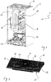
Fig. 1 schematically shows an axonometric view of a wall-mounted condensing boiler according to the invention; -
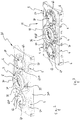
Fig. 2 shows an axonometric view of a component, object of the invention, of the condensing boiler ofFig. 1 ; -
Fig. 3 shows a rear view of the component ofFig. 2 ; -
Fig. 4 shows a variant of the component ofFig. 2 ; -
Figs. 5a and 5b show two axonometric views of the condensing boiler ofFig. 1 with its outer casing fully assembled and not. - The features of the invention are now described using the references in the figures. It is noted that the above figures, although schematic, reproduce the components of the device in proportions between their spatial dimensions and orientations which are compatible with a possible embodiment which is among the preferred ones. It is also noted that any dimensional and spatial term (such as "lower", "upper", "inner", "outer", "front", "rear" and the like) refers to the position according to which the cover and the condensing boiler are shown in the annexed figures.
- With reference to
Fig. 1 ,reference numeral 1 indicates a condensing boiler of which, for the purposes of the invention, there are only shown: acombustion unit 10, comprising a gas burner, the relative combustion chamber (not shown) and the primary "condensing"heat exchanger 11; therelative ventilation unit 12; thehydraulic unit 13 of which substantially only thesecondary heat exchanger 14 is shown for the production of domestic hot water. - The above components are arranged within a box enclosure 2 (also called "chassis") closed frontally by a front panel 20 (see, for example,
Fig. 5a ), below from a bottom panel (not shown) and on top substantially by awall 21 that for the purposes of the invention shall be called, hereinafter, "cover ortop 21". - The
outer enclosure 2 also acts as a sealedchamber 22 of thecondensing boiler 1 through dedicated and known sealed members. - What said thus far does not substantially depart from the prior art.
- However, according to the invention, said
cover 21, instead of being a flat sheet comprising at least a hole for coupling the fume exhaust and/or combustion air intake system is aclosing component 21 of plastic material implementing a plurality of functions. - More in particular, the
cover 21 comprises first setting means 3 for the coupling of a known fume exhaust and combustion air intake conduit of the "coaxial" type (hereinafter, called "coaxial conduit", for simplicity of description) and second setting means 4 for the coupling of a "split" fume exhaust and air intake system (hereinafter called "split system"). - Neither the coaxial conduits nor the split ones are shown in the figures annexed to the present description, being able to be similar to those of the prior art.
- As is instead clearly shown in
Fig. 2 , said first setting means 3 for coupling an "coaxial conduit" consist of a connectingcollar 30 totally similar to that of the prior art to be mounted (e.g., by screwing or welding), but integrally made with thecover 21 of theboiler 1. - Like the prior art solutions, therefore, also said
collar 30, communicating with the interior of the sealedchamber 22 of theboiler 1, is provided with thefume exhaust outlet 31 inside the combustion air intake annular one 32 so as to receive and couple with the respective exhaust and intake sections of the coaxial conduit. Thecoaxial collar 30 may further comprise integratedknown inlets 33 for the introduction of combustion fume analysis probes (not shown). - Sealing members between the
collar 30 and the lower end of the coaxial conduit ensure the tightness of the sealedchamber 22 of theboiler 1 closed by saidcover 21, as per the prior art. - On the other hand, the second setting means 4 for the coupling of a split exhaust system, also integrated to the
cover 21 of theboiler 1, comprise afirst coupling 41 for the fume exhaust conduit and at least asecond coupling 40 for the combustion air intake conduit. - According to the invention, said
first coupling 41 coincides with thefume exhaust 31 of thecoaxial collar 30 described above (in such case the lower end of the fume exhaust conduit shall be, as per prior art, suitably shaped and designed to obstruct and seal theannular outlet 32 of thesame collar 30, not used) while thesecond coupling 40 is a side opening suitable for receiving, as mentioned, the lower end of a combustion air intake conduit. - The opening 40 is normally closed by a
cap 42, integrally made with thecover 21, when thecondensing boiler 1 adopts a fume exhaust and air intake coaxial conduit; on the contrary, with "split systems" it must be removed in order to uncover therelative opening 40 for coupling the air conduit. - Preferably, said
cap 42 consists of ashell 42 integrally moulded with thecover 21; the zone of thecover 21 at the circumferential outer edge of thecap 42 has a reduced thickness compared to the surrounding portions so as to facilitate the cutting (e.g. by a cutter) of saidcap 42 and the total removal thereof. - By way of a non-limiting example, a thickness of about 0.5 mm is provided at the outer edge of said
cap 42 against an average thickness of the remaining zones of thecover 21 of about 2 mm. - The removal of
cap 42 may be eased by providing, in the proximity of its circumference, aco-moulded rubber cord 43 easily penetrable by a cutting tool and defining a guide for the cutting operation (seeFig. 4 ). - In order to satisfy any installation need, the
cover 21 may be made with a third coupling 40 (and relative cap 42), totally similar to the second but obtained symmetrically to it relative to the minor axis of thecover 21. - According to where the combustion air inlet is located from the outside and the path that the relative conduit must follow in order to reach
boiler 1, the installer may decide to open alternatively either one or theother coupling 40, according to a practice already used with the prior art systems and solutions. - According to another aspect of the invention,
reference elements 5 for fixing thefront panel 20 to theouter enclosure 2 of theboiler 1 may be also integrated on thecover 21. - As shown in
Fig. 2 , thereference elements 5 consist of a pair ofopposed tangs 50, projecting from the laying plane of thecover 21 and located at itsfront face 210, whereonrespective slots 201 of theupper edge 200 of the said front panel 20 (Fig. 5b ) engage (e.g., by shape coupling or by interference). - A plurality of
seats 6 for fixing (through screws or similar means) one or more components of thecondensing boiler 1 to thecover 21 may be provided, for example, at the rear edge 211 thereof (seeFig. 3 ). - Finally, it should be noted that the
cover 21 of the invention and the plurality of elements that it integrates, as already partly mentioned, is made by moulding of plastic material. - Therefore, it appears evident that with the
cover 21 of the invention the intended objects are achieved, in particular the possibility of integrating in a single component, which acts as an upper wall of the sealedchamber 22 of acondensing boiler 1, a plurality of elements that makes it compatible, without structural complications or installation difficulties, both with fume exhaust and combustion air intake "coaxial" and "split" systems. - The integration in the cover of a coaxial collar and caps for "split systems" also eliminates the requested operation for the fixing thereof and the components normally used (for example, fixing screws and gaskets) making, as a consequence, the assembly of the boiler much simpler and quicker; this also reduces the risk of an imperfect tightness of the sealed chamber, at least resulting from errors and/or inaccuracies in the mounting thereof and/or for dimensional imperfections of the elements to be coupled.
- Finally, the presence on the cover of reference elements for the fixing of the front panel facilitates and speeds up the composition of its outer enclosure.
Claims (11)
- Cover (21) for closing a sealed chamber (2; 22) of a condensing boiler (1) on which at least one exhaust conduit of the combustion fumes produced in said condensing boiler (1) and at least one conduit for the entry of combustion air required for said combustion are intended to fit, said cover (21)- acting as an upper wall of said sealed chamber (2; 22)- comprising setting means (3; 4) for said coupling of:- said at least one exhaust conduit of the combustion fumes, and- said at least one conduit for the entry of combustion air said setting means (3; 4) being integrated and integrally made with said cover (21)characterised in that
said setting means (3; 4) comprise:- first setting means (3) for a fume exhaust and combustion air intake conduit of the "coaxial" type, said first setting means (3) comprising, in turn, a coaxial collar (30) integrally made with said cover (21) and comprising a fume exhaust outlet (31) within the annular air intake (32)- second setting means (4) for a combustion fume exhaust and combustion air intake system of a "split system", said second setting means (4), integrated and integrally made with said cover (21) comprising:said cover (21) being suitable with both "coaxial system" and "split system" for the discharge of combustion fumes and for the intake of combustion air.- a first coupling (41) for a combustion fume exhaust conduit, said first coupling (41) comprising said fume exhaust outlet (31) of said coaxial collar (30),- at least a second coupling (40) for a combustion air intake conduit, said second coupling (40) comprising an opening (40) adapted to accommodate the lower end of said combustion air intake conduit, - Cover (21) according to the previous claim,
characterised in that
said at least one second coupling (40) is closed by a cap (42), integrally made with said cover (21), said cap (42) being subject to:- remain closed when said condensing boiler (1) adopts a fume exhaust and combustion air intake conduit of the "coaxial" type,- be removed when said condensing boiler (1) adopts a fume exhaust and combustion air intake system of the "split" type. - Cover (21) according to the previous claim,
characterised in that
said cap (42) consists of a shell (42), integrally moulded with said cover (21), whose external circumferential edge has reduced thickness compared to the surrounding areas of said cover (21), said reduced thickness facilitating cutting and total removal operations of said cap (42) from said cover (21). - Cover (21) according to the previous claim,
characterised in that
in the proximity of the circumference of said cap (42), a co-moulded rubber cord (43) may be provided, said cord (43) being easily penetrable by a cutting tool and defining a guide for the cutting operation of said cap (42), whose total removal is simplified. - Cover (21) according to any previous claim
characterised in that
said at least one second coupling (40) for a combustion air intake conduit consists of a pair of couplings (40). - Cover (21) according to any previous claim
characterised in that
said coaxial collar (30) comprises integrated inlets (33) for the introduction of combustion fume analysis probes. - Cover (21) according to any previous claim
characterised in that it further comprises reference elements (5) for fixing a front panel (20) of the outer box enclosure (2) of said condensing boiler (1), said reference elements (5) being made at the front face (210) of said cover (21). - Cover (21) according to the previous claim,
characterised in that
said reference elements (5) comprise a pair of tangs (50), projecting from the laying plane of said cover (21), on said tangs (50) engaging respective slots (201) of the upper edge (200) of said front panel (20). - Cover (21) according to any previous claim
characterised in that
a plurality of seats (6) is provided on the rear edge (211) of said cover (21) for fixing one or more components of said condensing boiler (1). - Cover (21) according to any previous claim
characterised in that it is made by moulding of plastic material. - Condensing boiler (1) comprising the cover (21) according to one or more of claims 1 to 10.
Applications Claiming Priority (2)
| Application Number | Priority Date | Filing Date | Title |
|---|---|---|---|
| IT000237A ITAN20130237A1 (en) | 2013-12-10 | 2013-12-10 | COVER FOR CONDENSING BOILERS |
| PCT/IB2014/002415 WO2015087119A1 (en) | 2013-12-10 | 2014-11-07 | Cover for condensing boilers |
Publications (2)
| Publication Number | Publication Date |
|---|---|
| EP3071898A1 EP3071898A1 (en) | 2016-09-28 |
| EP3071898B1 true EP3071898B1 (en) | 2020-02-05 |
Family
ID=49958518
Family Applications (1)
| Application Number | Title | Priority Date | Filing Date |
|---|---|---|---|
| EP14809509.4A Active EP3071898B1 (en) | 2013-12-10 | 2014-11-07 | Cover for condensing boilers |
Country Status (6)
| Country | Link |
|---|---|
| EP (1) | EP3071898B1 (en) |
| CN (1) | CN105814372B (en) |
| ES (1) | ES2786256T3 (en) |
| IT (1) | ITAN20130237A1 (en) |
| RU (1) | RU2647741C1 (en) |
| WO (1) | WO2015087119A1 (en) |
Families Citing this family (2)
| Publication number | Priority date | Publication date | Assignee | Title |
|---|---|---|---|---|
| GB2594969B (en) * | 2020-05-13 | 2024-05-29 | Bosch Thermotechnology Ltd Uk | Heating device and air box |
| IT202100028832A1 (en) | 2021-11-12 | 2023-05-12 | Riello Spa | A CONDENSING BOILER WITH AN IMPROVED TOP UNIT FOR CONNECTION TO THE EXHAUST GAS AND COMBUSTION AIR SUPPLY DUCTS |
Family Cites Families (11)
| Publication number | Priority date | Publication date | Assignee | Title |
|---|---|---|---|---|
| SU8595A1 (en) * | 1927-08-05 | 1929-03-30 | В.А. Яхимович | Boiler for central water heating |
| FR2452059A1 (en) * | 1979-03-21 | 1980-10-17 | Saunier Duval | DEVICE FOR EXHAUSTING BURNED GASES AND FOR SUPPLYING FRESH AIR FOR GAS WATERTIGHT APPLIANCES |
| WO1982001764A1 (en) * | 1980-11-07 | 1982-05-27 | Charron Jean C | Steamtight boiler with cylindrical exchanger |
| FR2493968B1 (en) * | 1980-11-07 | 1985-10-11 | Sdecc | WATERPROOF BOILER WITH CYLINDRICAL EXCHANGER |
| FR2504659B1 (en) * | 1981-04-28 | 1985-12-13 | Sdecc | SAFETY DEVICE FOR FLEXIBLE WALL COMBUSTION CHAMBER |
| FR2534005A1 (en) * | 1982-10-05 | 1984-04-06 | Sdecc | ARRANGEMENT OF A FORCE DRAIN GAS BOILER |
| RU2090804C1 (en) * | 1996-04-22 | 1997-09-20 | Рафаэл Газетов | Generator heat utilizer |
| IT246830Y1 (en) * | 1999-06-30 | 2002-04-10 | Baxi Spa | DEVICE TO ADJUST THE COMBUSTION AIR FLOW RATE IN A WATERPROOF CHAMBER |
| KR101049411B1 (en) * | 2009-06-16 | 2011-07-14 | 주식회사 경동나비엔 | Condensing boiler |
| IT1396921B1 (en) * | 2009-11-12 | 2012-12-20 | Unical Ag Spa | HEAT EXCHANGER WITH PERFECT FUME EXHAUST DEVICE |
| US8851022B2 (en) * | 2010-10-05 | 2014-10-07 | Laars Heating Systems Company | Water heating system and method for using the same |
-
2013
- 2013-12-10 IT IT000237A patent/ITAN20130237A1/en unknown
-
2014
- 2014-11-07 WO PCT/IB2014/002415 patent/WO2015087119A1/en not_active Ceased
- 2014-11-07 ES ES14809509T patent/ES2786256T3/en active Active
- 2014-11-07 RU RU2016126514A patent/RU2647741C1/en active
- 2014-11-07 CN CN201480067246.9A patent/CN105814372B/en active Active
- 2014-11-07 EP EP14809509.4A patent/EP3071898B1/en active Active
Non-Patent Citations (1)
| Title |
|---|
| None * |
Also Published As
| Publication number | Publication date |
|---|---|
| EP3071898A1 (en) | 2016-09-28 |
| ITAN20130237A1 (en) | 2015-06-11 |
| WO2015087119A1 (en) | 2015-06-18 |
| ES2786256T3 (en) | 2020-10-09 |
| CN105814372B (en) | 2018-11-09 |
| CN105814372A (en) | 2016-07-27 |
| RU2647741C1 (en) | 2018-03-19 |
Similar Documents
| Publication | Publication Date | Title |
|---|---|---|
| AU2020205360B2 (en) | Cap and water-heating device including the same | |
| US5749355A (en) | Multi-position furnace with condensing heat exchanger | |
| US8056552B2 (en) | Wall thimble with outside air inlet | |
| US8408196B2 (en) | Ceiling support box with outside air inlet | |
| US10088156B2 (en) | Water heater venting assembly | |
| US9140450B2 (en) | Retrofitted corrosive resistant venting system | |
| WO2015087119A1 (en) | Cover for condensing boilers | |
| EP2995880B1 (en) | Improved boiler heat exchanger | |
| US3552377A (en) | Conduit assembly | |
| EP3264005B1 (en) | Sealed air boiler air inlet chamber | |
| FR2871739B1 (en) | HOUSING WITH EXTERNAL SEAL COVER AND CALIPER FOR A HEATING, VENTILATION AND / OR AIR CONDITIONING FACILITY | |
| US8230849B2 (en) | Wall thimble with outside air inlet | |
| ITMI990439U1 (en) | ASSEMBLY FOR FINNED HEAT EXCHANGER TERMINAL | |
| CN107576066B (en) | Indoor combustion device | |
| CA2840652A1 (en) | Dual category venting system | |
| US4286570A (en) | Efficiency heater | |
| CN213630923U (en) | Combustion apparatus | |
| ITAN20130108U1 (en) | COVER FOR CONDENSING BOILERS | |
| CN211781995U (en) | gas water heater | |
| CN210697368U (en) | Lid parts, body parts and food processor | |
| EP2623883B1 (en) | Heating device with removable front cover, method for maintaining a heating device | |
| ITMI20130401A1 (en) | PERFECTED HEAT EXCHANGER FOR BOILER | |
| HK40061894A (en) | Hot water supply device | |
| JP2020169634A (en) | Gasket attachment structure and gasket | |
| HK40061894B (en) | Hot water supply device |
Legal Events
| Date | Code | Title | Description |
|---|---|---|---|
| PUAI | Public reference made under article 153(3) epc to a published international application that has entered the european phase |
Free format text: ORIGINAL CODE: 0009012 |
|
| 17P | Request for examination filed |
Effective date: 20160519 |
|
| AK | Designated contracting states |
Kind code of ref document: A1 Designated state(s): AL AT BE BG CH CY CZ DE DK EE ES FI FR GB GR HR HU IE IS IT LI LT LU LV MC MK MT NL NO PL PT RO RS SE SI SK SM TR |
|
| AX | Request for extension of the european patent |
Extension state: BA ME |
|
| DAX | Request for extension of the european patent (deleted) | ||
| STAA | Information on the status of an ep patent application or granted ep patent |
Free format text: STATUS: EXAMINATION IS IN PROGRESS |
|
| 17Q | First examination report despatched |
Effective date: 20190214 |
|
| GRAP | Despatch of communication of intention to grant a patent |
Free format text: ORIGINAL CODE: EPIDOSNIGR1 |
|
| STAA | Information on the status of an ep patent application or granted ep patent |
Free format text: STATUS: GRANT OF PATENT IS INTENDED |
|
| INTG | Intention to grant announced |
Effective date: 20190827 |
|
| GRAS | Grant fee paid |
Free format text: ORIGINAL CODE: EPIDOSNIGR3 |
|
| GRAA | (expected) grant |
Free format text: ORIGINAL CODE: 0009210 |
|
| STAA | Information on the status of an ep patent application or granted ep patent |
Free format text: STATUS: THE PATENT HAS BEEN GRANTED |
|
| AK | Designated contracting states |
Kind code of ref document: B1 Designated state(s): AL AT BE BG CH CY CZ DE DK EE ES FI FR GB GR HR HU IE IS IT LI LT LU LV MC MK MT NL NO PL PT RO RS SE SI SK SM TR |
|
| REG | Reference to a national code |
Ref country code: GB Ref legal event code: FG4D |
|
| REG | Reference to a national code |
Ref country code: AT Ref legal event code: REF Ref document number: 1230199 Country of ref document: AT Kind code of ref document: T Effective date: 20200215 |
|
| REG | Reference to a national code |
Ref country code: DE Ref legal event code: R096 Ref document number: 602014060636 Country of ref document: DE |
|
| REG | Reference to a national code |
Ref country code: IE Ref legal event code: FG4D Ref country code: RO Ref legal event code: EPE |
|
| REG | Reference to a national code |
Ref country code: CH Ref legal event code: EP |
|
| REG | Reference to a national code |
Ref country code: NL Ref legal event code: MP Effective date: 20200205 |
|
| PG25 | Lapsed in a contracting state [announced via postgrant information from national office to epo] |
Ref country code: RS Free format text: LAPSE BECAUSE OF FAILURE TO SUBMIT A TRANSLATION OF THE DESCRIPTION OR TO PAY THE FEE WITHIN THE PRESCRIBED TIME-LIMIT Effective date: 20200205 Ref country code: PT Free format text: LAPSE BECAUSE OF FAILURE TO SUBMIT A TRANSLATION OF THE DESCRIPTION OR TO PAY THE FEE WITHIN THE PRESCRIBED TIME-LIMIT Effective date: 20200628 Ref country code: NO Free format text: LAPSE BECAUSE OF FAILURE TO SUBMIT A TRANSLATION OF THE DESCRIPTION OR TO PAY THE FEE WITHIN THE PRESCRIBED TIME-LIMIT Effective date: 20200505 Ref country code: FI Free format text: LAPSE BECAUSE OF FAILURE TO SUBMIT A TRANSLATION OF THE DESCRIPTION OR TO PAY THE FEE WITHIN THE PRESCRIBED TIME-LIMIT Effective date: 20200205 |
|
| REG | Reference to a national code |
Ref country code: LT Ref legal event code: MG4D |
|
| PG25 | Lapsed in a contracting state [announced via postgrant information from national office to epo] |
Ref country code: LV Free format text: LAPSE BECAUSE OF FAILURE TO SUBMIT A TRANSLATION OF THE DESCRIPTION OR TO PAY THE FEE WITHIN THE PRESCRIBED TIME-LIMIT Effective date: 20200205 Ref country code: HR Free format text: LAPSE BECAUSE OF FAILURE TO SUBMIT A TRANSLATION OF THE DESCRIPTION OR TO PAY THE FEE WITHIN THE PRESCRIBED TIME-LIMIT Effective date: 20200205 Ref country code: BG Free format text: LAPSE BECAUSE OF FAILURE TO SUBMIT A TRANSLATION OF THE DESCRIPTION OR TO PAY THE FEE WITHIN THE PRESCRIBED TIME-LIMIT Effective date: 20200505 Ref country code: GR Free format text: LAPSE BECAUSE OF FAILURE TO SUBMIT A TRANSLATION OF THE DESCRIPTION OR TO PAY THE FEE WITHIN THE PRESCRIBED TIME-LIMIT Effective date: 20200506 Ref country code: SE Free format text: LAPSE BECAUSE OF FAILURE TO SUBMIT A TRANSLATION OF THE DESCRIPTION OR TO PAY THE FEE WITHIN THE PRESCRIBED TIME-LIMIT Effective date: 20200205 Ref country code: IS Free format text: LAPSE BECAUSE OF FAILURE TO SUBMIT A TRANSLATION OF THE DESCRIPTION OR TO PAY THE FEE WITHIN THE PRESCRIBED TIME-LIMIT Effective date: 20200605 |
|
| PG25 | Lapsed in a contracting state [announced via postgrant information from national office to epo] |
Ref country code: NL Free format text: LAPSE BECAUSE OF FAILURE TO SUBMIT A TRANSLATION OF THE DESCRIPTION OR TO PAY THE FEE WITHIN THE PRESCRIBED TIME-LIMIT Effective date: 20200205 |
|
| REG | Reference to a national code |
Ref country code: ES Ref legal event code: FG2A Ref document number: 2786256 Country of ref document: ES Kind code of ref document: T3 Effective date: 20201009 |
|
| PG25 | Lapsed in a contracting state [announced via postgrant information from national office to epo] |
Ref country code: SK Free format text: LAPSE BECAUSE OF FAILURE TO SUBMIT A TRANSLATION OF THE DESCRIPTION OR TO PAY THE FEE WITHIN THE PRESCRIBED TIME-LIMIT Effective date: 20200205 Ref country code: CZ Free format text: LAPSE BECAUSE OF FAILURE TO SUBMIT A TRANSLATION OF THE DESCRIPTION OR TO PAY THE FEE WITHIN THE PRESCRIBED TIME-LIMIT Effective date: 20200205 Ref country code: EE Free format text: LAPSE BECAUSE OF FAILURE TO SUBMIT A TRANSLATION OF THE DESCRIPTION OR TO PAY THE FEE WITHIN THE PRESCRIBED TIME-LIMIT Effective date: 20200205 Ref country code: DK Free format text: LAPSE BECAUSE OF FAILURE TO SUBMIT A TRANSLATION OF THE DESCRIPTION OR TO PAY THE FEE WITHIN THE PRESCRIBED TIME-LIMIT Effective date: 20200205 Ref country code: SM Free format text: LAPSE BECAUSE OF FAILURE TO SUBMIT A TRANSLATION OF THE DESCRIPTION OR TO PAY THE FEE WITHIN THE PRESCRIBED TIME-LIMIT Effective date: 20200205 Ref country code: LT Free format text: LAPSE BECAUSE OF FAILURE TO SUBMIT A TRANSLATION OF THE DESCRIPTION OR TO PAY THE FEE WITHIN THE PRESCRIBED TIME-LIMIT Effective date: 20200205 |
|
| REG | Reference to a national code |
Ref country code: DE Ref legal event code: R097 Ref document number: 602014060636 Country of ref document: DE |
|
| REG | Reference to a national code |
Ref country code: AT Ref legal event code: MK05 Ref document number: 1230199 Country of ref document: AT Kind code of ref document: T Effective date: 20200205 |
|
| PLBE | No opposition filed within time limit |
Free format text: ORIGINAL CODE: 0009261 |
|
| STAA | Information on the status of an ep patent application or granted ep patent |
Free format text: STATUS: NO OPPOSITION FILED WITHIN TIME LIMIT |
|
| 26N | No opposition filed |
Effective date: 20201106 |
|
| PG25 | Lapsed in a contracting state [announced via postgrant information from national office to epo] |
Ref country code: AT Free format text: LAPSE BECAUSE OF FAILURE TO SUBMIT A TRANSLATION OF THE DESCRIPTION OR TO PAY THE FEE WITHIN THE PRESCRIBED TIME-LIMIT Effective date: 20200205 |
|
| PG25 | Lapsed in a contracting state [announced via postgrant information from national office to epo] |
Ref country code: PL Free format text: LAPSE BECAUSE OF FAILURE TO SUBMIT A TRANSLATION OF THE DESCRIPTION OR TO PAY THE FEE WITHIN THE PRESCRIBED TIME-LIMIT Effective date: 20200205 Ref country code: SI Free format text: LAPSE BECAUSE OF FAILURE TO SUBMIT A TRANSLATION OF THE DESCRIPTION OR TO PAY THE FEE WITHIN THE PRESCRIBED TIME-LIMIT Effective date: 20200205 |
|
| REG | Reference to a national code |
Ref country code: DE Ref legal event code: R119 Ref document number: 602014060636 Country of ref document: DE |
|
| PG25 | Lapsed in a contracting state [announced via postgrant information from national office to epo] |
Ref country code: MC Free format text: LAPSE BECAUSE OF FAILURE TO SUBMIT A TRANSLATION OF THE DESCRIPTION OR TO PAY THE FEE WITHIN THE PRESCRIBED TIME-LIMIT Effective date: 20200205 |
|
| REG | Reference to a national code |
Ref country code: CH Ref legal event code: PL |
|
| GBPC | Gb: european patent ceased through non-payment of renewal fee |
Effective date: 20201107 |
|
| PG25 | Lapsed in a contracting state [announced via postgrant information from national office to epo] |
Ref country code: LU Free format text: LAPSE BECAUSE OF NON-PAYMENT OF DUE FEES Effective date: 20201107 |
|
| REG | Reference to a national code |
Ref country code: BE Ref legal event code: MM Effective date: 20201130 |
|
| PG25 | Lapsed in a contracting state [announced via postgrant information from national office to epo] |
Ref country code: LI Free format text: LAPSE BECAUSE OF NON-PAYMENT OF DUE FEES Effective date: 20201130 Ref country code: CH Free format text: LAPSE BECAUSE OF NON-PAYMENT OF DUE FEES Effective date: 20201130 |
|
| REG | Reference to a national code |
Ref country code: ES Ref legal event code: PC2A Owner name: ARISTON THERMO ITALIA S.P.A. Effective date: 20210826 |
|
| PG25 | Lapsed in a contracting state [announced via postgrant information from national office to epo] |
Ref country code: IE Free format text: LAPSE BECAUSE OF NON-PAYMENT OF DUE FEES Effective date: 20201107 |
|
| PG25 | Lapsed in a contracting state [announced via postgrant information from national office to epo] |
Ref country code: DE Free format text: LAPSE BECAUSE OF NON-PAYMENT OF DUE FEES Effective date: 20210601 Ref country code: GB Free format text: LAPSE BECAUSE OF NON-PAYMENT OF DUE FEES Effective date: 20201107 |
|
| REG | Reference to a national code |
Ref country code: ES Ref legal event code: PC2A Owner name: ARISTON THERMO S.P.A. Effective date: 20220517 |
|
| PG25 | Lapsed in a contracting state [announced via postgrant information from national office to epo] |
Ref country code: TR Free format text: LAPSE BECAUSE OF FAILURE TO SUBMIT A TRANSLATION OF THE DESCRIPTION OR TO PAY THE FEE WITHIN THE PRESCRIBED TIME-LIMIT Effective date: 20200205 Ref country code: MT Free format text: LAPSE BECAUSE OF FAILURE TO SUBMIT A TRANSLATION OF THE DESCRIPTION OR TO PAY THE FEE WITHIN THE PRESCRIBED TIME-LIMIT Effective date: 20200205 Ref country code: CY Free format text: LAPSE BECAUSE OF FAILURE TO SUBMIT A TRANSLATION OF THE DESCRIPTION OR TO PAY THE FEE WITHIN THE PRESCRIBED TIME-LIMIT Effective date: 20200205 |
|
| PG25 | Lapsed in a contracting state [announced via postgrant information from national office to epo] |
Ref country code: MK Free format text: LAPSE BECAUSE OF FAILURE TO SUBMIT A TRANSLATION OF THE DESCRIPTION OR TO PAY THE FEE WITHIN THE PRESCRIBED TIME-LIMIT Effective date: 20200205 Ref country code: AL Free format text: LAPSE BECAUSE OF FAILURE TO SUBMIT A TRANSLATION OF THE DESCRIPTION OR TO PAY THE FEE WITHIN THE PRESCRIBED TIME-LIMIT Effective date: 20200205 |
|
| PG25 | Lapsed in a contracting state [announced via postgrant information from national office to epo] |
Ref country code: BE Free format text: LAPSE BECAUSE OF NON-PAYMENT OF DUE FEES Effective date: 20201130 |
|
| REG | Reference to a national code |
Ref country code: ES Ref legal event code: PC2A Owner name: ARISTON S.P.A. Effective date: 20220907 |
|
| P01 | Opt-out of the competence of the unified patent court (upc) registered |
Effective date: 20230515 |
|
| PGFP | Annual fee paid to national office [announced via postgrant information from national office to epo] |
Ref country code: FR Payment date: 20251125 Year of fee payment: 12 |
|
| PGFP | Annual fee paid to national office [announced via postgrant information from national office to epo] |
Ref country code: RO Payment date: 20251103 Year of fee payment: 12 |
|
| PGFP | Annual fee paid to national office [announced via postgrant information from national office to epo] |
Ref country code: ES Payment date: 20251229 Year of fee payment: 12 |
|
| PGFP | Annual fee paid to national office [announced via postgrant information from national office to epo] |
Ref country code: IT Payment date: 20260410 Year of fee payment: 13 |