EP3070979B1 - Method and device for processing failure in operator shared network - Google Patents
Method and device for processing failure in operator shared network Download PDFInfo
- Publication number
- EP3070979B1 EP3070979B1 EP13899001.5A EP13899001A EP3070979B1 EP 3070979 B1 EP3070979 B1 EP 3070979B1 EP 13899001 A EP13899001 A EP 13899001A EP 3070979 B1 EP3070979 B1 EP 3070979B1
- Authority
- EP
- European Patent Office
- Prior art keywords
- base station
- operator
- faulty
- network
- identifier
- Prior art date
- Legal status (The legal status is an assumption and is not a legal conclusion. Google has not performed a legal analysis and makes no representation as to the accuracy of the status listed.)
- Active
Links
- 238000000034 method Methods 0.000 title claims description 50
- 238000012545 processing Methods 0.000 title claims description 29
- 238000001514 detection method Methods 0.000 claims description 15
- 238000004891 communication Methods 0.000 description 16
- 238000010586 diagram Methods 0.000 description 15
- 230000011664 signaling Effects 0.000 description 8
- 230000002159 abnormal effect Effects 0.000 description 7
- 230000006870 function Effects 0.000 description 6
- 238000001228 spectrum Methods 0.000 description 5
- 238000006243 chemical reaction Methods 0.000 description 4
- 230000007246 mechanism Effects 0.000 description 4
- 238000005457 optimization Methods 0.000 description 4
- 230000008878 coupling Effects 0.000 description 3
- 238000010168 coupling process Methods 0.000 description 3
- 238000005859 coupling reaction Methods 0.000 description 3
- 230000000694 effects Effects 0.000 description 3
- 230000008569 process Effects 0.000 description 3
- 230000001413 cellular effect Effects 0.000 description 2
- 238000005516 engineering process Methods 0.000 description 2
- 230000006872 improvement Effects 0.000 description 2
- 238000012544 monitoring process Methods 0.000 description 2
- 238000003672 processing method Methods 0.000 description 2
- JZEPSDIWGBJOEH-UHFFFAOYSA-N 4-decylbicyclo[2.2.1]hept-2-ene Chemical compound C1CC2C=CC1(CCCCCCCCCC)C2 JZEPSDIWGBJOEH-UHFFFAOYSA-N 0.000 description 1
- 230000009286 beneficial effect Effects 0.000 description 1
- 238000010276 construction Methods 0.000 description 1
- 238000013461 design Methods 0.000 description 1
- 239000000284 extract Substances 0.000 description 1
- 230000003287 optical effect Effects 0.000 description 1
- GOLXNESZZPUPJE-UHFFFAOYSA-N spiromesifen Chemical compound CC1=CC(C)=CC(C)=C1C(C(O1)=O)=C(OC(=O)CC(C)(C)C)C11CCCC1 GOLXNESZZPUPJE-UHFFFAOYSA-N 0.000 description 1
Images


Classifications
-
- H—ELECTRICITY
- H04—ELECTRIC COMMUNICATION TECHNIQUE
- H04W—WIRELESS COMMUNICATION NETWORKS
- H04W24/00—Supervisory, monitoring or testing arrangements
- H04W24/04—Arrangements for maintaining operational condition
-
- H—ELECTRICITY
- H04—ELECTRIC COMMUNICATION TECHNIQUE
- H04L—TRANSMISSION OF DIGITAL INFORMATION, e.g. TELEGRAPHIC COMMUNICATION
- H04L43/00—Arrangements for monitoring or testing data switching networks
- H04L43/10—Active monitoring, e.g. heartbeat, ping or trace-route
-
- H—ELECTRICITY
- H04—ELECTRIC COMMUNICATION TECHNIQUE
- H04W—WIRELESS COMMUNICATION NETWORKS
- H04W24/00—Supervisory, monitoring or testing arrangements
- H04W24/08—Testing, supervising or monitoring using real traffic
-
- H—ELECTRICITY
- H04—ELECTRIC COMMUNICATION TECHNIQUE
- H04W—WIRELESS COMMUNICATION NETWORKS
- H04W36/00—Hand-off or reselection arrangements
- H04W36/34—Reselection control
- H04W36/38—Reselection control by fixed network equipment
Definitions
- the present invention relates to network sharing technologies in network communications, and in particular, to a method and an apparatus for processing a fault in a multi-operator core network.
- a network sharing (Network sharing) technology can implement that multiple operators (Operator) provide services for respective users by using one shared mobile network, thereby greatly reducing costs of repeated construction of mobile networks.
- This type of sharing usually causes increased network complexity. Particularly when the network is faulty, processing becomes more difficult.
- Atypical scenario is that services provided by multiple operators exist in a cell (Cell) within coverage of one base station.
- Networks of the operators in the cell may be referred to as PLMNs (Public Land Mobile Network, public land mobile network) of the operators.
- the PLMNs of the operators share a RAN (Radio Access Network, radio access network) of the cell.
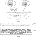
- a fault occurs in a network of an operator at a moment because of some reasons. For example, an S1 link from the RAN to an MME (Mobility Management Entity, mobility management entity) is broken, as shown in FIG. 1 . Because there is no corresponding processing method currently, an abnormal phenomenon may occur, such as a phenomenon that UE (user equipment, User Equipment) still attempts to access the faulty network of the operator, causing a negative impact.
- MME Mobility Management Entity
- US 2005/0090255 A1 discloses a method for access network sharing, for example, a GSM or UMTS 3G wireless communication radio access network (RAN) among multiple core networks, for example, wireless communication services networks, including transmitting information about the core network sharing the common access network, e.g., a pseudo network identity or the number of core networks sharing the common access network or pointer information, in a system information message.
- the communication device uses the information provided in the system information message to connect to a core network. If a connection attempt sent by a communication device is unsuccessful, the communication device receives a connection rejection from the network. The communication device may use this information to prevent future attempts to connect to certain core networks.
- ETSI TS 136 304 V11.5.0 relates to Evolve Universal Terrestrial Radio Access (E-UTRA); User Equipment (UE) procedures in idle mode. It specifies the access stratum (AS) part of the idle mode procedure applicable to a UE. It further specifies the model for the functional division between the non-access stratum (NAS) and AS in a UE.
- E-UTRA Evolve Universal Terrestrial Radio Access
- UE User Equipment
- AS access stratum
- NAS non-access stratum
- US 2013/0301609 A1 relates to methods and systems for managing and monitoring allocation of RF spectrum resources based on time, space and frequency.
- a network may be enabled to allocate access spectrum resources for use by other network providers on a real-time basis. Allocated resources may be transferred from one provider with access resources to another in need of additional resources based on contractual terms or on real-time purchase negotiations and settlement.
- a network may be enabled to monitor the use of allocated resources on real-time basis and offload or allow additional users depending on the spectrum resources' availability.
- Public safety networks may be enabled to make spectrum resources available to the general public by allocating spectrum resources and monitoring the use of those resources. During an emergency, when traffic increases on the public safety network, the public safety network may offload bandwidth traffic to make necessary resources available for public safety users.
- US 2013/0183971 A1 relates to systems or methods for managing a handover (e.g. over a Un or Uu connection or interface) of a relay from an eNB such as source eNB to another eNB such as a target eNB, where the source eNB or DeNB may provide a backhaul link to the relay and the relay may provide an access link to a user equipment.
- a handover e.g. over a Un or Uu connection or interface
- a handover e.g. over a Un or Uu connection or interface
- RAN radio access network
- MME mobility management entity
- E-RAB EUTRAN radio access bearer
- US 8,565,689 B1 discloses improved capabilities for increasing the bandwidths in a large area broadband network where an optimization server is incorporated within the wireless network in association with the public data network gateway, which may be deployed in regional areas, thus reducing the time latency for applications being run from a mobile cellular device. Further, by associating additional optimization servers at base stations, application functionality may be optionally transferred from the regional optimization server to the local base station optimization servers in instances where a number of mobile cellular devices are requesting the same data via the access through the same cell, and in other instances, to the effect that backhaul network bandwidth utilization is reduced or eliminated.
- an objective of embodiments of the present invention is to provide a method and an apparatus for processing a fault in a multi-operator core network, to prevent UE in a multi-operator core network from accessing an operator whose network is faulty within coverage of a base station.
- an apparatus for processing a fault in a multi-operator core network is provided, applied to a first base station, where multiple operators share a network within coverage of the first base station, and the apparatus includes:
- the apparatus further includes: an adjacent-base station notification unit, configured to notify a second base station adjacent to the first base station of the identifier of the faulty operator, so that the second base station forbids UE served by the second base station to be handed over to the network of the faulty operator within coverage of the first base station.
- an adjacent-base station notification unit configured to notify a second base station adjacent to the first base station of the identifier of the faulty operator, so that the second base station forbids UE served by the second base station to be handed over to the network of the faulty operator within coverage of the first base station.
- the apparatus further includes: a UE access stopping unit, configured to: when receiving a UE handover request sent by a second base station adjacent to the first base station, reject the UE handover request, where the UE handover request is a request, of UE served by the second base station, for being handed over to the network of the faulty operator within coverage of the first base station.
- a UE access stopping unit configured to: when receiving a UE handover request sent by a second base station adjacent to the first base station, reject the UE handover request, where the UE handover request is a request, of UE served by the second base station, for being handed over to the network of the faulty operator within coverage of the first base station.
- the apparatus further includes: a fault detection unit, configured to perform heartbeat detection on links from networks of the operators within coverage of the first base station to the core network, to learn whether there is an operator whose network is faulty.
- an apparatus for processing a fault in a multi-operator core network applied to UE served by a first base station, where multiple operators share a network within coverage of the first base station, and the apparatus includes:
- a method for processing a fault in a multi-operator core network is provided, applied to a first base station, where multiple operators share a network within coverage of the first base station, and the method includes:
- the method further includes:
- the notifying a second base station adjacent to the first base station of the identifier of the faulty operator includes: notifying the second base station of the identifier of the faulty operator by sending an X2 configuration update message to the second base station, where the X2 configuration update message carries the identifier of the faulty operator.
- the notifying a second base station adjacent to the first base station of the identifier of the faulty operator includes: sending an alarm to an operation support system OSS, so that the OSS notifies the second base station that the network of the faulty operator is faulty within coverage of the first base station.
- the method further includes:
- the method further includes:
- a method for processing a fault in a multi-operator core network is provided, applied to UE served by a first base station, where multiple operators share a network within coverage of the first base station, and the method includes:
- Some beneficial effects of the present invention may include: In a scenario in which multiple operators share a network within coverage of a base station, when a network of one operator is faulty or networks of some operators are faulty (for example, an S1 link is faulty), in the embodiments of the present invention, UE served by the base station may be notified of an identifier of the faulty operator by using a specified message (such as a SIB message), so that the UE can correctly determine which operators have a network fault, thereby avoiding an abnormal phenomenon such as a phenomenon that the UE still attempts to access the network of the faulty operator.
- a specified message such as a SIB message
- a base station usually notifies, by broadcasting a SIB (System Information Block) message, UE of an operator network that exists in a cell of the second base station.
- SIB System Information Block
- UE can be notified, at best, that there is an operator fault, but cannot be further notified of specific operator or operators that are faulty in the prior art. Therefore, the UE cannot identify the faulty operator.
- the UE intends to perform selection or reselection, if a target operator happens to be the faulty operator, an abnormal phenomenon in which the UE repeatedly initiates a connection but the connection is repeatedly released occurs.
- FIG. 2 is an exemplary flowchart of a method according to Embodiment 1 of the present invention.
- this embodiment provides a method for processing a fault in a multi-operator core network, applied to a first base station, where multiple operators share a network within coverage of the first base station, and the method includes:
- the specified message may be a SIB message
- a cell barred cellBarred field of the SIB message includes a faulty-operator list
- the faulty-operator list includes the identifier of the faulty operator.
- the method may include:
- the method may further include:
- UE served by the base station may be notified of an identifier of the faulty operator by using a specified message (such as a SIB message), so that the UE can correctly determine which operators have a network fault, thereby avoiding an abnormal phenomenon such as a phenomenon that the UE still attempts to access the network of the faulty operator.
- a specified message such as a SIB message
- FIG. 3 is a schematic signaling diagram of a method according to Embodiment 2 of the present invention. This embodiment is based on Embodiment 1, and provides further details about Embodiment 1.
- cellBarred cell barred
- Table 1 SystemlnformationBlock field descriptions cellBarred barred means the cell is barred, as defined in TS 36.304 [4].
- cellReservedForOperatorUse As defined in TS 36.304 [4].
- csg-Indication If set to TRUE the UE is only allowed to access the cell if it is a CSG member cell or if selected during manual CSG selection, see TS 36.304 [4].
- freqBandIndicator Defined in TS 36.101 [42, table 5.5-1].
- ims-EmergencySupport Indicates whether the cell supports IMS emergency bearer services for UEs in limited service mode. If absent, IMS emergency call is not supported by the network in the cell for UEs in limited service mode.
- intraFreqReselection Used to control cell reselection to intra-frequency cells when the highest ranked cell is barred, or treated as barred by the UE, as specified in TS 36.304 [4].
- plmn-IdentityList List of PLMN identities The first listed PLMN-Identity is the primary PLMN.
- the foregoing manner is applicable to a case in which there is only one operator served by a first base station, because in this case, when the operator is faulty, it can be deduced that the cell cannot be accessed.
- this manner has a limitation, because in this case, when one operator is faulty, it does not mean that another operator is also faulty. Therefore, in this case, an indication of the cellBarred field is fuzzy, and therefore, the UE cannot identify the faulty operator among the operators, and further cannot take right measures.
- the cellBarred field in the SIB message is extended in this embodiment, and a faulty-operator list (that is, CellBarredPlmnList in Table 2) is added.
- the faulty-operator list may be used to provide a list of identifiers of faulty operators, that is, indicate which specific operator or operators are faulty. That is, in this embodiment, universal cellBarred for all operator networks (PLMN) is changed into cellBarred for each individual PLMN.
- PLMN universal cellBarred for all operator networks
- the UE may choose not to access the operators served by the first base station that are in the list, but choose to access another operator served by the first base station, or choose to access another base station, and so on.
- cellBarred barred means the cell is barred, as defined in TS 36.304 [4].
- csg-Indication If set to TRUE the UE is only allowed to access the cell if it is a CSG member cell or if selected during manual CSG selection, see TS 36.304 [4].
- freqBandIndicator Defined in TS 36.101 [42, table 5.5-1].
- ims-EmergencySupport Indicates whether the cell supports IMS emergency bearer services for UEs in limited service mode. If absent, IMS emergency call is not supported by the network in the cell for UEs in limited service mode.
- intraFreqReselection Used to control cell reselection to intra-frequency cells when the highest ranked cell is barred, or treated as barred by the UE, as specified in TS 36.304 [4].
- plmn-IdentityList List of PLMN identities The first listed PLMN-Identity is the primary PLMN.
- this embodiment may include the following steps: From the perspective of the first base station:
- the SIB message may also be extended in another manner, or another system message is extended, or a new massage is defined, to carry an identifier of a faulty operator, which is not limited in this embodiment of the present invention, and none of the manners that may be used herein departs from the protection scope of the present invention.
- UE served by the base station may be notified of an identifier of the faulty operator by using a specified message (such as a SIB message), so that the UE can correctly determine which operators have a network fault, thereby avoiding an abnormal phenomenon such as a phenomenon that the UE still attempts to access the network of the faulty operator.
- a specified message such as a SIB message
- the first base station may notify, by extending the SIB message, a UE in a cell of the first base station of operators that have a link fault, thereby avoiding an access error of the UE and resolving a basic problem that arises when a fault occurs in a multi-operator core network.
- the faulty base station (that is, the first base station) may further notify an adjacent base station (that is, a second base station) of fault information of the operator, so that the adjacent base station performs a corresponding reaction, thereby further improving a fault processing mechanism.
- the method may further include:
- the method may include:
- the first base station may notify the second base station of the identifier of the faulty operator in multiple manners. Some examples are given below:
- the acquiring an identifier of a faulty operator served by a first base station includes: acquiring, by receiving an OSS notification, the identifier of the faulty operator served by the first base station.
- FIG. 5 is a schematic signaling diagram of a second implementation manner according to Embodiment 3 of the present invention, which may include the following steps:
- a faulty base station (that is, the first base station) further notifies an adjacent base station (that is, the second base station) of fault information of an operator, so that the adjacent base station learns which PLMNs within coverage of the faulty base station are faulty, so as to perform a corresponding reaction, thereby further improving a fault processing mechanism.
- This embodiment is based on the foregoing embodiment, and is a further extension and improvement on the foregoing embodiment.
- the adjacent base station can actively prevent UE served by the adjacent base station from being handed over to the faulty operator served by the first base station (refer to Embodiment 3). But if the adjacent base station is not notified in time, there may still be UE that intends to be handed over from the adjacent base station to the faulty operator served by the first base station.
- the first base station may actively reject the handover requested by the UE served by the adjacent base station. That is, in this embodiment, for the first base station, the method may further include:
- FIG. 6 is a schematic signaling diagram of a method according to Embodiment 4 of the present invention, which may include the following steps:
- the first base station actively rejects the handover requested by the UE served by the adjacent base station, thereby avoiding a negative effect such as a phenomenon that the UE repeatedly initiates a connection but the connection is repeatedly released.
- this embodiment of the present invention further provides an apparatus for processing a fault in a multi-operator core network.
- This embodiment provides an apparatus 700 for processing a fault in a multi-operator core network, as shown in FIG. 7 .
- the apparatus 700 is applied to a first base station, multiple operators share a network within coverage of the first base station, and the apparatus 700 may include:
- the specified message is a system information block SIB message
- a cell barred cellBarred field of the SIB message includes a faulty-operator list
- the faulty-operator list includes the identifier of the faulty operator.
- the apparatus 700 may further include: an adjacent-base station notification unit, configured to notify a second base station adjacent to the first base station of the identifier of the faulty operator, so that the second base station forbids UE served by the second base station to be handed over to the network of the faulty operator within coverage of the first base station.
- an adjacent-base station notification unit configured to notify a second base station adjacent to the first base station of the identifier of the faulty operator, so that the second base station forbids UE served by the second base station to be handed over to the network of the faulty operator within coverage of the first base station.
- the apparatus 700 may further include: a UE access stopping unit, configured to: when receiving a UE handover request sent by a second base station adjacent to the first base station, reject the UE handover request, where the UE handover request is a request, of UE served by the second base station, for being handed over to the network of the faulty operator within coverage of the first base station.
- a UE access stopping unit configured to: when receiving a UE handover request sent by a second base station adjacent to the first base station, reject the UE handover request, where the UE handover request is a request, of UE served by the second base station, for being handed over to the network of the faulty operator within coverage of the first base station.
- the apparatus 700 may further include: a fault detection unit, configured to perform heartbeat detection on links from networks of the operators within coverage of the first base station to the core network, to learn whether there is an operator whose network is faulty.
- a fault detection unit configured to perform heartbeat detection on links from networks of the operators within coverage of the first base station to the core network, to learn whether there is an operator whose network is faulty.
- UE served by the base station may be notified of an identifier of the faulty operator by using a specified message (such as a SIB message), so that the UE can correctly determine which operators have a network fault, thereby avoiding an abnormal phenomenon such as a phenomenon that the UE still attempts to access the network of the faulty operator.
- a specified message such as a SIB message
- an apparatus 800 for processing a fault in a multi-operator core network may be further correspondingly provided, as shown in FIG. 8 .
- the apparatus 800 is applied to the second base station, and may include:
- a faulty base station (that is, the first base station) further notifies an adjacent base station (that is, the second base station) of fault information of an operator, so that the adjacent base station learns which PLMNs within coverage of the faulty base station are faulty, so as to perform a corresponding reaction, thereby further improving a fault processing mechanism.
- an apparatus 900 for processing a fault in a multi-operator core network may be further correspondingly provided, as shown in FIG. 9 .
- the apparatus 900 is applied to the UE served by the first base station, multiple operators share a network within coverage of the first base station, and the apparatus 900 may include:
- the first base station actively rejects the handover requested by the UE served by the adjacent base station, thereby avoiding a negative effect such as a phenomenon that the UE repeatedly initiates a connection but the connection is repeatedly released.
- An apparatus embodiment basically corresponds to a method embodiment, and therefore for related parts, reference may be made to partial descriptions in the method embodiment.
- the described apparatus embodiment is merely exemplary.
- the units described as separate parts may or may not be physically separate, and parts displayed as units may or may not be physical units, may be located in one position, or may be distributed on a plurality of network units. Some or all of the modules may be selected according to actual requirements to achieve the objectives of the solutions of the embodiments. A person of ordinary skill in the art may understand and implement the embodiments of the present invention without creative efforts.
- An apparatus for processing a fault in a multi-operator core network may be implemented based on a computer system.
- the foregoing fault processing method may be implemented on the fault processing apparatus based on the computer system, that is, a fault processing device. Therefore, this embodiment provides a device 1000 for processing a fault in a multi-operator core network, as shown in FIG. 10 .
- the device 1000 is applied to a first base station, multiple operators share a network within coverage of the first base station, and the device 1000 may include a processor 1001, a memory 1002, a communications interface 1003, and a bus 1004.
- the processor 1001, the memory 1002, and the communications interface 1003 are connected to and communicate with each other by using the bus 1004.
- the memory 1002 is configured to store a program instruction.
- the processor 1001 is configured to invoke the program instruction stored in the memory 1002, to execute the following operations: acquiring an identifier of a faulty operator, where the faulty operator is an operator whose network is faulty within coverage of the first base station; sending a specified message by using the communications interface 1003; and notifying UE served by the first base station of the identifier of the faulty operator, so that the UE served by the first base station no longer accesses the network of the faulty operator within coverage of the first base station, where the specified message includes the identifier of the faulty operator.
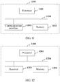
- a device 1100 for processing a fault in a multi-operator core network is further correspondingly provided, as shown in FIG. 11 .
- the device 1100 is applied to the second base station and may include a processor 1101, a memory 1102, a communications interface 1103, and a bus 1104.
- the processor 1101, the memory 1102, and the communications interface 1103 are connected to and communicate with each other by using the bus 1104.
- the memory 1102 is configured to store a program instruction.
- the processor 1101 is configured to invoke the program instruction stored in the memory 1102, to execute the following operations: receiving, by using the communications interface 1103, information carrying an identifier of a faulty operator served by a first base station, where the first base station is an adjacent base station of the second base station, and the faulty operator is an operator whose network is faulty within coverage of the first base station; and forbidding, according to the identifier of the faulty operator, UE served by the second base station to be handed over to the network of the faulty operator within coverage of the first base station.
- UE served by the base station may be notified of an identifier of the faulty operator by using a specified message (such as a SIB message), so that the UE can correctly determine which operators have a network fault, thereby avoiding an abnormal phenomenon such as a phenomenon that the UE still attempts to access the network of the faulty operator.
- a specified message such as a SIB message
- a faulty base station (that is, the first base station) further notifies an adjacent base station (that is, the second base station) of fault information of an operator, so that the adjacent base station learns which PLMNs within coverage of the faulty base station are faulty, so as to perform a corresponding reaction, thereby further improving a fault processing mechanism.
- a device 1200 for processing a fault in a multi-operator core network may be further correspondingly provided, as shown in FIG. 12 .
- Multiple operators share a network within coverage of the first base station, and the device 1200 may include a processor 1201, a memory 1202, a receiver 1203, and a bus 1204.
- the processor 1201, the memory 1202, and the receiver 1203 are connected to and communicate with each other by using the bus 1204.
- the memory 1202 is configured to store a program instruction.
- the processor 1201 is configured to invoke the program instruction stored in the memory 1202, to execute the following operations: receiving a specified message of the first base station by using the receiver 1203, where the specified message includes an identifier of a faulty operator, and the faulty operator is an operator whose network is faulty within coverage of the first base station; and stopping, according to the identifier of the faulty operator, sending a request for accessing the network of the faulty operator within coverage of the first base station.
- the first base station actively rejects the handover requested by the UE served by the adjacent base station, thereby avoiding a negative impact such as a phenomenon that the UE repeatedly initiates a connection but the connection is repeatedly released.
- the disclosed system, device, and method may be implemented in other manners.
- the described device embodiment is merely exemplary.
- the unit division is merely logical function division and may be other division in actual implementation.
- a plurality of units or components may be combined or integrated into another system, or some features may be ignored or not performed.
- the displayed or discussed mutual couplings or direct couplings or communication connections may be implemented by using some interfaces.
- the indirect couplings or communication connections between the devices or units may be implemented in electronic, mechanical, or other forms.
- the units described as separate parts may or may not be physically separate, and parts displayed as units may or may not be physical units, may be located in one position, or may be distributed on a plurality of network units. Some or all of the units may be selected according to actual needs to achieve the objectives of the solutions of the embodiments.
- functional units in the embodiments of the present invention may be integrated into one processing unit, or each of the units may exist alone physically, or two or more units are integrated into one unit.
- the functions When the functions are implemented in the form of a software functional unit and sold or used as an independent product, the functions may be stored in a computer-readable storage medium. Based on such an understanding, the technical solutions of the present invention essentially, or the part contributing to the prior art, or a part of the technical solutions may be implemented in a form of a software product.
- the software product is stored in a storage medium and includes several instructions for instructing a computer device (which may be a personal computer, a server, or a network device) or a processor (processor) to perform all or some of the steps of the methods described in the embodiments of the present invention.
- the foregoing storage medium includes: any medium that can store program code, such as a USB flash drive, a removable hard disk, a read-only memory (ROM, Read-Only Memory), a random access memory (RAM, Random Access Memory), a magnetic disk, or an optical disc.
- program code such as a USB flash drive, a removable hard disk, a read-only memory (ROM, Read-Only Memory), a random access memory (RAM, Random Access Memory), a magnetic disk, or an optical disc.
Description
- The present invention relates to network sharing technologies in network communications, and in particular, to a method and an apparatus for processing a fault in a multi-operator core network.
- A network sharing (Network sharing) technology can implement that multiple operators (Operator) provide services for respective users by using one shared mobile network, thereby greatly reducing costs of repeated construction of mobile networks. However, despite many advantages, this type of sharing usually causes increased network complexity. Particularly when the network is faulty, processing becomes more difficult.
- Atypical scenario is that services provided by multiple operators exist in a cell (Cell) within coverage of one base station. Networks of the operators in the cell may be referred to as PLMNs (Public Land Mobile Network, public land mobile network) of the operators. The PLMNs of the operators share a RAN (Radio Access Network, radio access network) of the cell. A fault occurs in a network of an operator at a moment because of some reasons. For example, an S1 link from the RAN to an MME (Mobility Management Entity, mobility management entity) is broken, as shown in
FIG. 1 . Because there is no corresponding processing method currently, an abnormal phenomenon may occur, such as a phenomenon that UE (user equipment, User Equipment) still attempts to access the faulty network of the operator, causing a negative impact. -
US 2005/0090255 A1 discloses a method for access network sharing, for example, a GSM or UMTS 3G wireless communication radio access network (RAN) among multiple core networks, for example, wireless communication services networks, including transmitting information about the core network sharing the common access network, e.g., a pseudo network identity or the number of core networks sharing the common access network or pointer information, in a system information message. The communication device uses the information provided in the system information message to connect to a core network. If a connection attempt sent by a communication device is unsuccessful, the communication device receives a connection rejection from the network. The communication device may use this information to prevent future attempts to connect to certain core networks. - ETSI TS 136 304 V11.5.0 relates to Evolve Universal Terrestrial Radio Access (E-UTRA); User Equipment (UE) procedures in idle mode. It specifies the access stratum (AS) part of the idle mode procedure applicable to a UE. It further specifies the model for the functional division between the non-access stratum (NAS) and AS in a UE.
-
US 2013/0301609 A1 relates to methods and systems for managing and monitoring allocation of RF spectrum resources based on time, space and frequency. A network may be enabled to allocate access spectrum resources for use by other network providers on a real-time basis. Allocated resources may be transferred from one provider with access resources to another in need of additional resources based on contractual terms or on real-time purchase negotiations and settlement. A network may be enabled to monitor the use of allocated resources on real-time basis and offload or allow additional users depending on the spectrum resources' availability. Public safety networks may be enabled to make spectrum resources available to the general public by allocating spectrum resources and monitoring the use of those resources. During an emergency, when traffic increases on the public safety network, the public safety network may offload bandwidth traffic to make necessary resources available for public safety users. -
US 2013/0183971 A1 relates to systems or methods for managing a handover (e.g. over a Un or Uu connection or interface) of a relay from an eNB such as source eNB to another eNB such as a target eNB, where the source eNB or DeNB may provide a backhaul link to the relay and the relay may provide an access link to a user equipment. To manage the handover, access information may be received and a determination may be made regarding whether one or more target eNBs may be capable of holding the relay based on the access information. Additionally, the relay that may be handed over may be configured to use radio access network (RAN) sharing, a mobility management entity (MME) may be selected, and/or a EUTRAN radio access bearer (E-RAB) may be modified. -
US 8,565,689 B1 discloses improved capabilities for increasing the bandwidths in a large area broadband network where an optimization server is incorporated within the wireless network in association with the public data network gateway, which may be deployed in regional areas, thus reducing the time latency for applications being run from a mobile cellular device. Further, by associating additional optimization servers at base stations, application functionality may be optionally transferred from the regional optimization server to the local base station optimization servers in instances where a number of mobile cellular devices are requesting the same data via the access through the same cell, and in other instances, to the effect that backhaul network bandwidth utilization is reduced or eliminated. - In view of this, an objective of embodiments of the present invention is to provide a method and an apparatus for processing a fault in a multi-operator core network, to prevent UE in a multi-operator core network from accessing an operator whose network is faulty within coverage of a base station.
- The invention is set out in the appended set of claims. The embodiments, aspects and/or examples of the following description which are not covered by the appended claims are considered as not being part of the present invention.
- To resolve the foregoing technical problem, the embodiments of the present invention disclose the following technical solutions:
According to a first aspect, an apparatus for processing a fault in a multi-operator core network is provided, applied to a first base station, where multiple operators share a network within coverage of the first base station, and the apparatus includes: - a faulty-operator identifier acquiring unit, configured to acquire an identifier of a faulty operator, where the faulty operator is an operator whose network is faulty within coverage of the first base station; and
- a UE notification unit, configured to notify UE served by the first base station of the identifier of the faulty operator by broadcasting a SIB message constructed by the first base, where
- a cell barred, cellBarred, field of the constructed SIB message comprises a faulty-operator list, and the faulty-operator list includes the identifier of the faulty operator.
- With reference to the first aspect, in a first possible implementation manner, the apparatus further includes:
an adjacent-base station notification unit, configured to notify a second base station adjacent to the first base station of the identifier of the faulty operator, so that the second base station forbids UE served by the second base station to be handed over to the network of the faulty operator within coverage of the first base station. - With reference to the first aspect, in a second possible implementation manner, the apparatus further includes:
a UE access stopping unit, configured to: when receiving a UE handover request sent by a second base station adjacent to the first base station, reject the UE handover request, where the UE handover request is a request, of UE served by the second base station, for being handed over to the network of the faulty operator within coverage of the first base station. - With reference to the first aspect, in a third possible implementation manner, the apparatus further includes:
a fault detection unit, configured to perform heartbeat detection on links from networks of the operators within coverage of the first base station to the core network, to learn whether there is an operator whose network is faulty. - According to a second aspect, an apparatus for processing a fault in a multi-operator core network is provided, applied to UE served by a first base station, where multiple operators share a network within coverage of the first base station, and the apparatus includes:
- a message receiving unit, configured to receive a system information block, SIB, message broadcast by the first base station, wherein a cell barred, cellBarred, field of the SIB message comprises a faulty-operator list, and the faulty-operator list includes an identifier of a faulty operator, and the faulty operator is an operator whose network is faulty within coverage of the first base station; and
- an access stopping unit, configured to stop, according to the identifier of the faulty operator, sending a request for accessing the network of the faulty operator within coverage of the first base station.
- According to a third aspect, a method for processing a fault in a multi-operator core network is provided, applied to a first base station, where multiple operators share a network within coverage of the first base station, and the method includes:
- acquiring an identifier of a faulty operator, where the faulty operator is an operator whose network is faulty within coverage of the first base station;
- constructing a system information block, SIB, message carrying a faulty-operator list, wherein a cell barred, cellBarred, field of the SIB message comprises the faulty-operator list, and the faulty-operator list comprises the identifier of the faulty operator; and
- notifying UE served by the first base station of the identifier of the faulty operator by broadcasting (S303) the SIB message.
- With reference to the third aspect, in a first possible implementation manner, the method further includes:
- after the acquiring an identifier of a faulty operator,
- notifying a second base station adjacent to the first base station of the identifier of the faulty operator, so that the second base station forbids UE served by the second base station to be handed over to the network of the faulty operator within coverage of the first base station.
- With reference to the first possible implementation manner of the third aspect, in a second possible implementation manner,
the notifying a second base station adjacent to the first base station of the identifier of the faulty operator includes:
notifying the second base station of the identifier of the faulty operator by sending an X2 configuration update message to the second base station, where the X2 configuration update message carries the identifier of the faulty operator. - With reference to the first possible implementation manner of the third aspect, in a third possible implementation manner,
the notifying a second base station adjacent to the first base station of the identifier of the faulty operator includes:
sending an alarm to an operation support system OSS, so that the OSS notifies the second base station that the network of the faulty operator is faulty within coverage of the first base station. - With reference to the third aspect, in a fourth possible implementation manner, the method further includes:
- after the acquiring an identifier of a faulty operator,
- when receiving a UE handover request sent by a second base station adjacent to the first base station, rejecting the UE handover request, where the UE handover request is a request, of UE served by the second base station, of being handed over to the network of the faulty operator within coverage of the first base station.
- With reference to the third aspect, in a fifth possible implementation manner, the method further includes:
- before the acquiring an identifier of a faulty operator,
- performing heartbeat detection on links from networks of the operators within coverage of the first base station to the core network, to learn whether there is an operator whose network is faulty.
- According to a fourth aspect, a method for processing a fault in a multi-operator core network is provided, applied to UE served by a first base station, where multiple operators share a network within coverage of the first base station, and the method includes:
- receiving a a system information block, SIB, message broadcast by the first base station, wherein a cell barred, cellBarred, field of the SIB message comprises a faulty-operator list, and the faulty-operator list includes an identifier of a faulty operator, and the faulty operator is an operator whose network is faulty within coverage of the first base station; and
- stopping, according to the identifier of the faulty operator, sending a request for accessing the network of the faulty operator within coverage of the first base station.
- Some beneficial effects of the present invention may include:
In a scenario in which multiple operators share a network within coverage of a base station, when a network of one operator is faulty or networks of some operators are faulty (for example, an S1 link is faulty), in the embodiments of the present invention, UE served by the base station may be notified of an identifier of the faulty operator by using a specified message (such as a SIB message), so that the UE can correctly determine which operators have a network fault, thereby avoiding an abnormal phenomenon such as a phenomenon that the UE still attempts to access the network of the faulty operator. - It should be understood that the foregoing general description and the following detailed description are merely exemplary, and do not constitute limitations on the present disclosure.
- To describe the technical solutions in the embodiments of the present invention or in the prior art more clearly, the following briefly introduces the accompanying drawings required for describing the embodiments or the prior art. Apparently, the accompanying drawings in the following description show merely some embodiments of the present invention, and a person of ordinary skill in the art may still derive other drawings from these accompanying drawings without creative efforts.
-
FIG. 1 is a schematic diagram showing that a link is broken in a multi-operator core network; -
FIG. 2 is an exemplary flowchart of a method according toEmbodiment 1 of the present invention; -
FIG. 3 is a schematic signaling diagram of a method according to Embodiment 2 of the present invention; -
FIG. 4 is a schematic signaling diagram of a first implementation manner according to Embodiment 3 of the present invention; -
FIG. 5 is a schematic signaling diagram of a second implementation manner according to Embodiment 3 of the present invention; -
FIG. 6 is a schematic signaling diagram of a method according to Embodiment 4 of the present invention; -
FIG. 7 is a schematic diagram of an apparatus applied to a first base station according to Embodiment 5 of the present invention; -
FIG. 8 is a schematic diagram of an apparatus applied to a second base station according to Embodiment 5 of the present invention; -
FIG. 9 is a schematic diagram of an apparatus applied to UE according to Embodiment 5 of the present invention; -
FIG. 10 is a schematic diagram of a device applied to a first base station according to Embodiment 6 of the present invention; -
FIG. 11 is a schematic diagram of a device applied to a second base station according to Embodiment 6 of the present invention; and -
FIG. 12 is a schematic diagram of a device applied to UE according to Embodiment 6 of the present invention. - The foregoing accompanying drawings show specific embodiments of the present invention, and more detailed descriptions are provided in the following. The accompanying drawings and text descriptions are not intended to limit the scope of the idea of the present invention in any manner, but are intended to describe the concept of the present invention to a person skilled in the art with reference to specific embodiments.
- The following clearly and completely describes the technical solutions in the embodiments of the present invention with reference to the accompanying drawings in the embodiments of the present invention. Apparently, the described embodiments are merely some but not all of the embodiments of the present invention. All other embodiments obtained by a person of ordinary skill in the art based on the embodiments of the present invention without creative efforts shall fall within the protection scope of the present invention.
- Numerous specific details are mentioned in the following detailed descriptions to provide a thorough understanding of the present invention. However, a person skilled in the art should understand that the present invention may be implemented without these specific details. In other embodiments, a structure, a process, a component, and a circuit that are publicly known are not described in detail so as not to unnecessarily obscure the embodiments.
- In the prior art, a base station usually notifies, by broadcasting a SIB (System Information Block) message, UE of an operator network that exists in a cell of the second base station. However, during implementation of the present invention, it is found that in a case in which multiple operators share a network within coverage of a base station, when an S1 link of a network of an operator is faulty, UE can be notified, at best, that there is an operator fault, but cannot be further notified of specific operator or operators that are faulty in the prior art. Therefore, the UE cannot identify the faulty operator. When the UE intends to perform selection or reselection, if a target operator happens to be the faulty operator, an abnormal phenomenon in which the UE repeatedly initiates a connection but the connection is repeatedly released occurs.
-
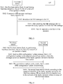
FIG. 2 is an exemplary flowchart of a method according toEmbodiment 1 of the present invention. To resolve the foregoing problem, this embodiment provides a method for processing a fault in a multi-operator core network, applied to a first base station, where multiple operators share a network within coverage of the first base station, and the method includes: - S201: Acquire an identifier of a faulty operator, where the faulty operator is an operator whose network is faulty within coverage of the first base station.
- S202: Notify UE served by the first base station of the identifier of the faulty operator by using a specified message, so that the UE served by the first base station no longer accesses the network of the faulty operator within coverage of the first base station, where the specified message includes the identifier of the faulty operator.
- In this embodiment, preferably, the specified message may be a SIB message, a cell barred cellBarred field of the SIB message includes a faulty-operator list, and the faulty-operator list includes the identifier of the faulty operator.
- The foregoing manner is equivalent to extending the cellBarred field of the SIB message. In some other embodiments of the present invention, another system message, for example, systeminfomodification in a paging message, may be used to carry the identifier of the faulty operator. In addition, a special message may be constructed and a new message format may be defined to carry the identifier of the faulty operator. A specific form of the specified message is not limited in the present invention. None of the messages that may be used herein departs from the protection scope of the present invention.
- The foregoing description is given from the perspective of a first base station. Correspondingly, from the perspective of UE, the method may include:
- receiving a specified message of the first base station, where the specified message includes an identifier of a faulty operator, and the faulty operator is an operator whose network is faulty within coverage of the first base station; and
- stopping, according to the identifier of the faulty operator, sending a request for accessing the network of the faulty operator within coverage of the first base station.
- In addition, in this embodiment or some other embodiments of the present invention, for the first base station, the method may further include:
- before the acquiring an identifier of a faulty operator, that is, before step S201,
- performing heartbeat (heat beat) detection on links from networks of the operators within coverage of the first base station to the core network, to learn whether there is an operator whose network is faulty. During the heartbeat detection, one side of two interconnected sides sends a very small data packet (that is, a heartbeat signal) to the other side at fixed time intervals, and the other side determines, according to needs, whether to reply after receiving the data packet. A function of the heartbeat detection is to confirm one fact: whether the two interconnected sides are both online in a case in which the two interconnected sides do not communicate with each other, or whether a communications link between the two sides is broken.
- In a scenario in which multiple operators share a network within coverage of a base station, when a network of one operator is faulty or networks of some operators are faulty (for example, an S1 link is faulty), in this embodiment, UE served by the base station may be notified of an identifier of the faulty operator by using a specified message (such as a SIB message), so that the UE can correctly determine which operators have a network fault, thereby avoiding an abnormal phenomenon such as a phenomenon that the UE still attempts to access the network of the faulty operator.
-
FIG. 3 is a schematic signaling diagram of a method according to Embodiment 2 of the present invention. This embodiment is based onEmbodiment 1, and provides further details aboutEmbodiment 1. - In the prior art, for some fields of a SIB message broadcast by a base station, refer to the following Table 1, where a cellBarred (cell barred) field is used to indicate whether access to a current cell is forbidden. If an operator of a cell is faulty, UE may not perform access according to the cellBarred field.
Table 1 SystemlnformationBlock field descriptions cellBarred barred means the cell is barred, as defined in TS 36.304 [4]. cellReservedForOperatorUse As defined in TS 36.304 [4]. csg-Identity Identity of the Closed Subscriber Group the cell belongs to. csg-Indication If set to TRUE the UE is only allowed to access the cell if it is a CSG member cell or if selected during manual CSG selection, see TS 36.304 [4]. freqBandIndicator Defined in TS 36.101 [42, table 5.5-1]. ims-EmergencySupport Indicates whether the cell supports IMS emergency bearer services for UEs in limited service mode. If absent, IMS emergency call is not supported by the network in the cell for UEs in limited service mode. intraFreqReselection Used to control cell reselection to intra-frequency cells when the highest ranked cell is barred, or treated as barred by the UE, as specified in TS 36.304 [4]. plmn-IdentityList List of PLMN identities. The first listed PLMN-Identity is the primary PLMN. - However, during implementation of the present invention, it is found that the foregoing manner is applicable to a case in which there is only one operator served by a first base station, because in this case, when the operator is faulty, it can be deduced that the cell cannot be accessed. However, when there are multiple operators served by the first base station, this manner has a limitation, because in this case, when one operator is faulty, it does not mean that another operator is also faulty. Therefore, in this case, an indication of the cellBarred field is fuzzy, and therefore, the UE cannot identify the faulty operator among the operators, and further cannot take right measures.
- In view of this, the cellBarred field in the SIB message is extended in this embodiment, and a faulty-operator list (that is, CellBarredPlmnList in Table 2) is added. The faulty-operator list may be used to provide a list of identifiers of faulty operators, that is, indicate which specific operator or operators are faulty. That is, in this embodiment, universal cellBarred for all operator networks (PLMN) is changed into cellBarred for each individual PLMN. After learning CellBarredPlmnList, the UE may choose not to access the operators served by the first base station that are in the list, but choose to access another operator served by the first base station, or choose to access another base station, and so on.
Table 2 SystemlnformationBlock field descriptions cellBarred barred means the cell is barred, as defined in TS 36.304 [4]. CellBarredPlmnList List of PLMN identities with cell barred. cellReservedForOperator Use As defined in TS 36.304 [4]. csg-Identity Identity of the Closed Subscriber Group the cell belongs to. csg-Indication If set to TRUE the UE is only allowed to access the cell if it is a CSG member cell or if selected during manual CSG selection, see TS 36.304 [4]. freqBandIndicator Defined in TS 36.101 [42, table 5.5-1]. ims-EmergencySupport Indicates whether the cell supports IMS emergency bearer services for UEs in limited service mode. If absent, IMS emergency call is not supported by the network in the cell for UEs in limited service mode. intraFreqReselection Used to control cell reselection to intra-frequency cells when the highest ranked cell is barred, or treated as barred by the UE, as specified in TS 36.304 [4]. plmn-IdentityList List of PLMN identities. The first listed PLMN-Identity is the primary PLMN. - Specifically, this embodiment may include the following steps:
From the perspective of the first base station: - S301: A first base station finds, by performing heartbeat detection, that an S1 link of a network of an operator is faulty.
- S302: Construct a SIB message carrying a faulty-operator list.
- S303: Broadcast the SIB message to UE.
- From the perspective of the UE:
- S304: After receiving the SIB message, the UE extracts the faulty-operator list from the SIB message.
- S305: The UE responds to the fault of the operator, for example, stops accessing the operator that is served by the first base station and that is in the list, or chooses to access another operator that is served by the first base station and that is not in the list, or chooses to access another base station, and so on.
- Certainly, the foregoing is merely an example. In some other embodiments of the present invention, the SIB message may also be extended in another manner, or another system message is extended, or a new massage is defined, to carry an identifier of a faulty operator, which is not limited in this embodiment of the present invention, and none of the manners that may be used herein departs from the protection scope of the present invention.
- In a scenario in which multiple operators share a network within coverage of a base station, when a network of one operator is faulty or networks of some operators are faulty (for example, an S1 link is faulty), in this embodiment, UE served by the base station may be notified of an identifier of the faulty operator by using a specified message (such as a SIB message), so that the UE can correctly determine which operators have a network fault, thereby avoiding an abnormal phenomenon such as a phenomenon that the UE still attempts to access the network of the faulty operator.
- This embodiment is based on the foregoing embodiment, and is a further extension and improvement of the foregoing embodiment. In the foregoing embodiment, the first base station may notify, by extending the SIB message, a UE in a cell of the first base station of operators that have a link fault, thereby avoiding an access error of the UE and resolving a basic problem that arises when a fault occurs in a multi-operator core network. In this embodiment, the faulty base station (that is, the first base station) may further notify an adjacent base station (that is, a second base station) of fault information of the operator, so that the adjacent base station performs a corresponding reaction, thereby further improving a fault processing mechanism.
- Specifically, in this embodiment, for the first base station, the method may further include:
- after acquiring an identifier of a faulty operator,
- notifying a second base station adjacent to the first base station of the identifier of the faulty operator, so that the second base station forbids UE served by the second base station to be handed over to the network of the faulty operator within coverage of the first base station.
- The foregoing description is given from the perspective of the first base station. From the perspective of the second base station, the method may include:
- acquiring an identifier of a faulty operator served by a first base station, where the first base station is an adjacent base station of the second base station, and the faulty operator is an operator whose network is faulty within coverage of the first base station; and
- forbidding, according to the identifier of the faulty operator, UE served by the second base station to be handed over to the network of the faulty operator within coverage of the first base station.
- During specific implementation, the first base station may notify the second base station of the identifier of the faulty operator in multiple manners. Some examples are given below:
- (1) In a first implementation manner, the notifying a second base station adjacent to the first base station of the identifier of the faulty operator may specifically include:
- notifying the second base station of the identifier of the faulty operator by sending an X2 configuration update message to the second base station, where the X2 configuration update message carries the identifier of the faulty operator.
- The foregoing description is given from the perspective of the first base station. From the perspective of the second base station,
- the acquiring an identifier of a faulty operator served by a first base station includes:
acquiring, by receiving an X2 configuration update message sent by the first base station, the identifier of the faulty operator served by the first base station, where the X2 configuration update message carries the identifier of the faulty operator.
FIG. 4 is a schematic signaling diagram of the first implementation manner according to Embodiment 3 of the present invention, which may include the following steps:
From the perspective of a first base station:- S401: The first base station finds, by performing heartbeat detection, that an S1 link of a network of an operator is broken.
- S402: Send an eNB configuration Update message, that is, X2 configuration update, to an adjacent second base station, where the message carries an identifier of the faulty operator served by the first base station.
From the perspective of the second base station:- S403: The second base station sends a acknowledgement, that is, sends eNB configuration Update Acknowledge.
- S404: The second base station forbids, according to the acquired identifier of the faulty operator served by the first base station, a UE in a cell of the second base station to be handed over to the network of the faulty operator within coverage of the first base station. Specifically, a Barred PLMN field may be added to a neighbor cell list (NCL, Neighbour Cell List) of the second base station, to indicate which operators in each neighbor cell of the second base station have a network fault.
It is easy to understand that a sequence of the two foregoing steps S403 and S404 may not be fixed.
- (2) In a second implementation manner, the notifying a second base station adjacent to the first base station of the identifier of the faulty operator includes:
sending an alarm to an OSS, so that the OSS notifies the second base station that the network of the faulty operator is faulty within coverage of the first base station. - The foregoing description is given from the perspective of the first base station. From the perspective of the second base station,
the acquiring an identifier of a faulty operator served by a first base station includes:
acquiring, by receiving an OSS notification, the identifier of the faulty operator served by the first base station. -
FIG. 5 is a schematic signaling diagram of a second implementation manner according to Embodiment 3 of the present invention, which may include the following steps: - S501: A first base station finds, by performing heartbeat detection, that an S1 link from a network (PLMN1) of an operator to an MME is broken.
- S502: The first base station sends broken link alarm information (broken alarm) to an OSS through itf-N (interface Northbound, interface northbound), where the alarm information carries an identifier of PLMN1.
- S503: The OSS notifies the second base station that the link of PLMN1 within coverage of the first base station is broken.
- S504: The second base station forbids UE in a cell of the second base station to be handed over to PLMN1 within coverage of the first base station.
- In this embodiment, a faulty base station (that is, the first base station) further notifies an adjacent base station (that is, the second base station) of fault information of an operator, so that the adjacent base station learns which PLMNs within coverage of the faulty base station are faulty, so as to perform a corresponding reaction, thereby further improving a fault processing mechanism.
- This embodiment is based on the foregoing embodiment, and is a further extension and improvement on the foregoing embodiment. After a link of an operator served by a first base station is faulty, if an adjacent base station is notified in time, the adjacent base station can actively prevent UE served by the adjacent base station from being handed over to the faulty operator served by the first base station (refer to Embodiment 3). But if the adjacent base station is not notified in time, there may still be UE that intends to be handed over from the adjacent base station to the faulty operator served by the first base station. In view of this, in this embodiment, the first base station may actively reject the handover requested by the UE served by the adjacent base station. That is, in this embodiment, for the first base station, the method may further include:
- after the acquiring an identifier of a faulty operator,
- when receiving a UE handover request sent by a second base station adjacent to the first base station, rejecting the UE handover request, where the UE handover request is a request, of UE served by the second base station, for being handed over to the network of the faulty operator within coverage of the first base station.
-
FIG. 6 is a schematic signaling diagram of a method according to Embodiment 4 of the present invention, which may include the following steps: - S601: A first base station finds, by performing heartbeat detection, that an S1 link of a network (PLMN1) of an operator is faulty.
- S602: A second base station sends a handover request (Handover request) for handover to PLMN1 to the first base station, where the handover request carries an identifier of PLMN1.
- S603: The first base station rejects the handover request, that is, sends HANDOVER PREPARATION FAILURE. Further, a cause value (Cause Value) may be extended in HANDOVER PREPARATION FAILURE, to indicate which operators served by the first base station have a broken link.
- In this embodiment, after a network of an operator becomes faulty within coverage of a first base station, if there still is UE that intends to be handed over from an adjacent base station to the faulty operator served by the first base station, the first base station actively rejects the handover requested by the UE served by the adjacent base station, thereby avoiding a negative effect such as a phenomenon that the UE repeatedly initiates a connection but the connection is repeatedly released.
- Corresponding to the foregoing embodiments of the method for processing a fault in a multi-operator core network of the present invention, this embodiment of the present invention further provides an apparatus for processing a fault in a multi-operator core network.
- This embodiment provides an
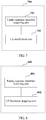
apparatus 700 for processing a fault in a multi-operator core network, as shown inFIG. 7 . Theapparatus 700 is applied to a first base station, multiple operators share a network within coverage of the first base station, and theapparatus 700 may include: - a faulty-operator
identifier acquiring unit 701, configured to acquire an identifier of a faulty operator, where the faulty operator is an operator whose network is faulty within coverage of the first base station; and - a
UE notification unit 702, configured to notify UE served by the first base station of the identifier of the faulty operator by sending a specified message, so that the UE served by the first base station no longer accesses the network of the faulty operator within coverage of the first base station, where - the specified message includes the identifier of the faulty operator.
- Preferably, the specified message is a system information block SIB message, a cell barred cellBarred field of the SIB message includes a faulty-operator list, and the faulty-operator list includes the identifier of the faulty operator.
- In this embodiment or some other embodiments of the present invention, the
apparatus 700 may further include:
an adjacent-base station notification unit, configured to notify a second base station adjacent to the first base station of the identifier of the faulty operator, so that the second base station forbids UE served by the second base station to be handed over to the network of the faulty operator within coverage of the first base station. - In this embodiment or some other embodiments of the present invention, the
apparatus 700 may further include:
a UE access stopping unit, configured to: when receiving a UE handover request sent by a second base station adjacent to the first base station, reject the UE handover request, where the UE handover request is a request, of UE served by the second base station, for being handed over to the network of the faulty operator within coverage of the first base station. - In addition, in this embodiment or some other embodiments of the present invention, the
apparatus 700 may further include:
a fault detection unit, configured to perform heartbeat detection on links from networks of the operators within coverage of the first base station to the core network, to learn whether there is an operator whose network is faulty. - In a scenario in which multiple operators share a network within coverage of a base station, when a network of one operator is faulty or networks of some operators are faulty (for example, an S1 link is faulty), in this embodiment, UE served by the base station may be notified of an identifier of the faulty operator by using a specified message (such as a SIB message), so that the UE can correctly determine which operators have a network fault, thereby avoiding an abnormal phenomenon such as a phenomenon that the UE still attempts to access the network of the faulty operator.
- In this embodiment, for the second base station, an
apparatus 800 for processing a fault in a multi-operator core network may be further correspondingly provided, as shown inFIG. 8 . Theapparatus 800 is applied to the second base station, and may include: - a faulty-operator
identifier receiving unit 801, configured to receive information that carries an identifier of a faulty operator served by a first base station, where the first base station is an adjacent base station of the second base station, and the faulty operator is an operator whose network is faulty within coverage of the first base station; and - a UE
handover stopping unit 802, configured to forbid, according to the identifier of the faulty operator, UE served by the second base station to be handed over to the network of the faulty operator within coverage of the first base station. - According to the foregoing
apparatus 800, a faulty base station (that is, the first base station) further notifies an adjacent base station (that is, the second base station) of fault information of an operator, so that the adjacent base station learns which PLMNs within coverage of the faulty base station are faulty, so as to perform a corresponding reaction, thereby further improving a fault processing mechanism. - In this embodiment, for the UE served by the first base station, an
apparatus 900 for processing a fault in a multi-operator core network may be further correspondingly provided, as shown inFIG. 9 . Theapparatus 900 is applied to the UE served by the first base station, multiple operators share a network within coverage of the first base station, and theapparatus 900 may include: - a
message receiving unit 901, configured to receive a specified message of the first base station, where the specified message includes an identifier of a faulty operator, and the faulty operator is an operator whose network is faulty within coverage of the first base station; and - an
access stopping unit 902, configured to stop, according to the identifier of the faulty operator, sending a request for accessing the network of the faulty operator within coverage of the first base station. - According to the foregoing
apparatus 900, after a network of an operator becomes faulty within coverage of a first base station, if there still is UE that intends to be handed over from an adjacent base station to the faulty operator served by the first base station, the first base station actively rejects the handover requested by the UE served by the adjacent base station, thereby avoiding a negative effect such as a phenomenon that the UE repeatedly initiates a connection but the connection is repeatedly released. - An apparatus embodiment basically corresponds to a method embodiment, and therefore for related parts, reference may be made to partial descriptions in the method embodiment. The described apparatus embodiment is merely exemplary. The units described as separate parts may or may not be physically separate, and parts displayed as units may or may not be physical units, may be located in one position, or may be distributed on a plurality of network units. Some or all of the modules may be selected according to actual requirements to achieve the objectives of the solutions of the embodiments. A person of ordinary skill in the art may understand and implement the embodiments of the present invention without creative efforts.
- An apparatus for processing a fault in a multi-operator core network provided in this embodiment of the present invention may be implemented based on a computer system. The foregoing fault processing method may be implemented on the fault processing apparatus based on the computer system, that is, a fault processing device. Therefore, this embodiment provides a
device 1000 for processing a fault in a multi-operator core network, as shown inFIG. 10 . Thedevice 1000 is applied to a first base station, multiple operators share a network within coverage of the first base station, and thedevice 1000 may include aprocessor 1001, amemory 1002, acommunications interface 1003, and abus 1004. - The
processor 1001, thememory 1002, and thecommunications interface 1003 are connected to and communicate with each other by using thebus 1004. - The
memory 1002 is configured to store a program instruction. - The
processor 1001 is configured to invoke the program instruction stored in thememory 1002, to execute the following operations: acquiring an identifier of a faulty operator, where the faulty operator is an operator whose network is faulty within coverage of the first base station; sending a specified message by using thecommunications interface 1003; and notifying UE served by the first base station of the identifier of the faulty operator, so that the UE served by the first base station no longer accesses the network of the faulty operator within coverage of the first base station, where the specified message includes the identifier of the faulty operator. - In this embodiment, for the second base station, a
device 1100 for processing a fault in a multi-operator core network is further correspondingly provided, as shown inFIG. 11 . Thedevice 1100 is applied to the second base station and may include aprocessor 1101, amemory 1102, acommunications interface 1103, and abus 1104. - The
processor 1101, thememory 1102, and thecommunications interface 1103 are connected to and communicate with each other by using thebus 1104. - The
memory 1102 is configured to store a program instruction. - The
processor 1101 is configured to invoke the program instruction stored in thememory 1102, to execute the following operations: receiving, by using thecommunications interface 1103, information carrying an identifier of a faulty operator served by a first base station, where the first base station is an adjacent base station of the second base station, and the faulty operator is an operator whose network is faulty within coverage of the first base station; and forbidding, according to the identifier of the faulty operator, UE served by the second base station to be handed over to the network of the faulty operator within coverage of the first base station. - In a scenario in which multiple operators share a network within coverage of a base station, when a network of one operator is faulty or networks of some operators are faulty (for example, an S1 link is faulty), in this embodiment, UE served by the base station may be notified of an identifier of the faulty operator by using a specified message (such as a SIB message), so that the UE can correctly determine which operators have a network fault, thereby avoiding an abnormal phenomenon such as a phenomenon that the UE still attempts to access the network of the faulty operator.
- In this embodiment, a faulty base station (that is, the first base station) further notifies an adjacent base station (that is, the second base station) of fault information of an operator, so that the adjacent base station learns which PLMNs within coverage of the faulty base station are faulty, so as to perform a corresponding reaction, thereby further improving a fault processing mechanism.
- In this embodiment, for the UE served by the first base station, a
device 1200 for processing a fault in a multi-operator core network may be further correspondingly provided, as shown inFIG. 12 . Multiple operators share a network within coverage of the first base station, and thedevice 1200 may include aprocessor 1201, amemory 1202, areceiver 1203, and abus 1204. - The
processor 1201, thememory 1202, and thereceiver 1203 are connected to and communicate with each other by using thebus 1204. - The
memory 1202 is configured to store a program instruction. - The
processor 1201 is configured to invoke the program instruction stored in thememory 1202, to execute the following operations: receiving a specified message of the first base station by using thereceiver 1203, where the specified message includes an identifier of a faulty operator, and the faulty operator is an operator whose network is faulty within coverage of the first base station; and stopping, according to the identifier of the faulty operator, sending a request for accessing the network of the faulty operator within coverage of the first base station. - In this embodiment, after a network of an operator becomes faulty within coverage of a first base station, if there still is UE that intends to be handed over from an adjacent base station to the faulty operator served by the first base station, the first base station actively rejects the handover requested by the UE served by the adjacent base station, thereby avoiding a negative impact such as a phenomenon that the UE repeatedly initiates a connection but the connection is repeatedly released.
- A person of ordinary skill in the art may be aware that, in combination with the examples described in the embodiments disclosed in this specification, units and algorithm steps may be implemented by electronic hardware or a combination of computer software and electronic hardware. Whether the functions are performed by hardware or software depends on particular applications and design constraint conditions of the technical solutions. A person skilled in the art may use different methods to implement the described functions for each particular application, but it should not be considered that the implementation goes beyond the scope of the present invention.
- It may be clearly understood by a person skilled in the art that, for the purpose of convenient and brief description, for a detailed working process of the foregoing system, device, and unit, reference may be made to a corresponding process in the foregoing method embodiments, and details are not described herein again.
- In the several embodiments provided in the present application, it should be understood that the disclosed system, device, and method may be implemented in other manners. For example, the described device embodiment is merely exemplary. For example, the unit division is merely logical function division and may be other division in actual implementation. For example, a plurality of units or components may be combined or integrated into another system, or some features may be ignored or not performed. In addition, the displayed or discussed mutual couplings or direct couplings or communication connections may be implemented by using some interfaces. The indirect couplings or communication connections between the devices or units may be implemented in electronic, mechanical, or other forms.
- The units described as separate parts may or may not be physically separate, and parts displayed as units may or may not be physical units, may be located in one position, or may be distributed on a plurality of network units. Some or all of the units may be selected according to actual needs to achieve the objectives of the solutions of the embodiments.
- In addition, functional units in the embodiments of the present invention may be integrated into one processing unit, or each of the units may exist alone physically, or two or more units are integrated into one unit.
- When the functions are implemented in the form of a software functional unit and sold or used as an independent product, the functions may be stored in a computer-readable storage medium. Based on such an understanding, the technical solutions of the present invention essentially, or the part contributing to the prior art, or a part of the technical solutions may be implemented in a form of a software product. The software product is stored in a storage medium and includes several instructions for instructing a computer device (which may be a personal computer, a server, or a network device) or a processor (processor) to perform all or some of the steps of the methods described in the embodiments of the present invention. The foregoing storage medium includes: any medium that can store program code, such as a USB flash drive, a removable hard disk, a read-only memory (ROM, Read-Only Memory), a random access memory (RAM, Random Access Memory), a magnetic disk, or an optical disc.
- The foregoing descriptions are merely specific implementation manners of the present invention, but are not intended to limit the protection scope of the present invention. Any variation or replacement readily figured out by a person skilled in the art within the technical scope disclosed in the present invention shall fall within the protection scope of the present invention. Therefore, the protection scope of the present invention shall be subject to the protection scope of the claims.
Claims (12)
- An apparatus (700), applied to a first base station in a multi-operator core network, wherein multiple operators share a network within coverage of the first base station, and the apparatus comprises:a user equipment, UE, notification unit (702), configured to broadcast system information block, SIB, messages;wherein the apparatus (700) is configured for processing a fault in the multi-operator core network and comprises a faulty-operator identifier acquiring unit (701), configured to acquire an identifier of a faulty operator, wherein the faulty operator is an operator whose network is faulty within coverage of the first base station; andthe UE notification unit (702) is configured to notify UE served by the first base station of the identifier of the faulty operator by broadcasting a SIB message constructed by the first base station to the UE, the apparatus being characterized in that, a cell barred, cellBarred, field of the constructed SIB message comprises a faulty-operator list, and the faulty-operator list comprises the identifier of the faulty operator.
- The apparatus according to claim 1, wherein the apparatus further comprises:
an adjacent-base station notification unit, configured to notify a second base station adjacent to the first base station of the identifier of the faulty operator, so that the second base station forbids a UE served by the second base station to be handed over to the network of the faulty operator within coverage of the first base station. - The apparatus according to claim 1, wherein the apparatus further comprises:
a UE access rejection unit, configured to: when receiving a UE handover request sent by a second base station adjacent to the first base station, reject the UE handover request, wherein the UE handover request is a request, of a UE served by the second base station, for being handed over to the network of the faulty operator within coverage of the first base station. - The apparatus according to claim 1, wherein the apparatus further comprises:
a fault detection unit, configured to perform heartbeat detection on links from networks of the operators within coverage of the first base station to a core network, to learn whether there is an operator whose network is faulty. - An apparatus (900), applied to user equipment, UE, served by a first base station in a multi-operator core network, wherein multiple operators share a network within coverage of the first base station, and the apparatus comprises:a message receiving unit (901), configured to receive system information block, SIB, messages broadcast by the first base station; andan access stopping unit (902), configured to stop sending a request for accessing a network within coverage of the first base station;wherein the apparatus (900) is configured for processing a fault in the multi-operator core network;the message receiving unit (901) is configured to receive a system information block, SIB, broadcast by the first base station, characterized in that the apparatus is configured to receive a cell barred, cellBarred, field of the SIB message comprising a faulty-operator list, the faulty-operator list comprises an identifier of a faulty operator, and the faulty operator is an operator whose network is faulty within coverage of the first base station; andthe access stopping unit (902) is configured to stop, according to the identifier of the faulty operator, sending a request for accessing the network of the faulty operator within coverage of the first base station.
- A method for processing a fault in a multi-operator core network, applied to a first base station in a multi-operator core network, wherein multiple operators share a network within coverage of the first base station, and the method comprises:acquiring (S201) an identifier of a faulty operator, wherein the faulty operator is an operator whose network is faulty within coverage of the first base station;constructing (S302) a system information block, SIB, message carrying a faulty-operator list, characterized in that a cell barred, cellBarred, field of the SIB message comprises the faulty-operator list, and the faulty-operator list comprises the identifier of the faulty operator; andnotifying (S202) a user equipment, UE, served by the first base station of the identifier of the faulty operator by broadcasting (S303) the SIB message to the UE served by the first base station.
- The method according to claim 6, wherein the method further comprises:after the acquiring an identifier of a faulty operator,notifying a second base station adjacent to the first base station of the identifier of the faulty operator, so that the second base station forbids UE served by the second base station to be handed over to the network of the faulty operator within coverage of the first base station.
- The method according to claim 7, wherein
the notifying a second base station adjacent to the first base station of the identifier of the faulty operator comprises:
notifying the second base station of the identifier of the faulty operator by sending an X2 configuration update message to the second base station, wherein the X2 configuration update message comprises the identifier of the faulty operator. - The method according to claim 7, wherein
the notifying a second base station adjacent to the first base station of the identifier of the faulty operator comprises:
sending an alarm to an operations support system OSS, so that the OSS notifies the second base station that the network of the faulty operator is faulty within coverage of the first base station. - The method according to claim 6, wherein the method further comprises:after acquiring an identifier of a faulty operator,when receiving a UE handover request sent by a second base station adjacent to the first base station, rejecting the UE handover request, wherein the UE handover request is a request, of UE served by the second base station, for being handed over to the network of the faulty operator within coverage of the first base station.
- The method according to claim 6, wherein the method further comprises:before acquiring an identifier of a faulty operator,performing heartbeat detection on links from networks of the operators within coverage of the first base station to a core network, to learn whether there is an operator whose network is faulty.
- A method for processing a fault in a multi-operator core network, applied to user equipment, UE, served by a first base station in a multi-operator core network, wherein multiple operators share a network within coverage of the first base station, and the method comprises:receiving a system information block, SIB, message broadcast by the first base station, characterized in that a cell barred, cellBarred, field of the SIB message comprises a faulty-operator list, and the faulty-operator list comprises an identifier of a faulty operator, and the faulty operator is an operator whose network is faulty within coverage of the first base station; andstopping, according to the identifier of the faulty operator, sending a request for accessing the network of the faulty operator within coverage of the first base station.
Applications Claiming Priority (1)
| Application Number | Priority Date | Filing Date | Title |
|---|---|---|---|
| PCT/CN2013/088961 WO2015085480A1 (en) | 2013-12-10 | 2013-12-10 | Method and device for processing failure in operator shared network |
Publications (3)
| Publication Number | Publication Date |
|---|---|
| EP3070979A1 EP3070979A1 (en) | 2016-09-21 |
| EP3070979A4 EP3070979A4 (en) | 2016-10-19 |
| EP3070979B1 true EP3070979B1 (en) | 2018-10-03 |
Family
ID=53370450
Family Applications (1)
| Application Number | Title | Priority Date | Filing Date |
|---|---|---|---|
| EP13899001.5A Active EP3070979B1 (en) | 2013-12-10 | 2013-12-10 | Method and device for processing failure in operator shared network |
Country Status (4)
| Country | Link |
|---|---|
| US (1) | US10178563B2 (en) |
| EP (1) | EP3070979B1 (en) |
| CN (1) | CN104919858B (en) |
| WO (1) | WO2015085480A1 (en) |
Families Citing this family (14)
| Publication number | Priority date | Publication date | Assignee | Title |
|---|---|---|---|---|
| EP3525520B1 (en) * | 2016-10-13 | 2021-05-26 | Huawei Technologies Co., Ltd. | Method and terminal for network switching |
| WO2019068257A1 (en) * | 2017-10-06 | 2019-04-11 | Fg Innovation Ip Company Limited | Systems and methods for cell (re) selection and cell barring |
| JP6996959B2 (en) * | 2017-12-11 | 2022-01-17 | エヌ・ティ・ティ・コミュニケーションズ株式会社 | Communication normality confirmation device, communication normality confirmation method, and program |
| ES2913538T3 (en) * | 2018-05-23 | 2022-06-02 | Exfo Oy | Subscriber identity detection method and arrangement |
| CN111325955A (en) * | 2018-12-17 | 2020-06-23 | 中国移动通信集团北京有限公司 | Intelligent well lid monitoring method, system, device and storage medium |
| CN111356163B (en) * | 2018-12-21 | 2023-06-13 | 海能达通信股份有限公司 | System information notification method, base station equipment and computer storage equipment |
| US11178559B2 (en) | 2019-07-17 | 2021-11-16 | T-Mobile Usa, Inc. | Cellular site monitoring systems and methods |
| CN113498063A (en) * | 2020-03-19 | 2021-10-12 | 中兴通讯股份有限公司 | Processing method and device for shared cell, electronic equipment and readable medium |
| WO2021212361A1 (en) * | 2020-04-22 | 2021-10-28 | Qualcomm Incorporated | Method to fast recover 5g service from abnormal data stop |
| USD951909S1 (en) * | 2020-07-06 | 2022-05-17 | Liu He | Headset |
| CN112291083B (en) * | 2020-09-30 | 2022-08-05 | 中国联合网络通信集团有限公司 | Data processing method, device and equipment |
| USD915348S1 (en) * | 2020-10-19 | 2021-04-06 | Shenzhen Qianhai Patuoxun Network And Technology Co., Ltd | Headphones |
| CN114697952B (en) * | 2020-12-29 | 2023-07-18 | 成都鼎桥通信技术有限公司 | Fault weakening processing method, device and communication system |
| CN116419306A (en) * | 2021-12-29 | 2023-07-11 | 华为技术有限公司 | Communication method and communication device |
Family Cites Families (30)
| Publication number | Priority date | Publication date | Assignee | Title |
|---|---|---|---|---|
| US6151620A (en) * | 1997-10-22 | 2000-11-21 | Novell, Inc. | Conference messaging system |
| US6466788B1 (en) * | 1998-12-21 | 2002-10-15 | Telefonaktiebolaget Lm Ericsson (Publ) | Methods and apparatus for transferring position data between terminals in wireless communications systems |
| ATE511736T1 (en) * | 2001-02-13 | 2011-06-15 | Ericsson Telefon Ab L M | TRANSMITTING FILTERING OR FILTERED INFORMATION THROUGH THE IUR INTERFACE |
| US6925492B2 (en) * | 2001-06-25 | 2005-08-02 | Sun Microsystems, Inc | Method and apparatus for automatic configuration of a cluster of computers |
| US20050090251A1 (en) * | 2003-10-07 | 2005-04-28 | Ravi Kuchibhotla | Apparatus and method for shared network |
| US7561879B2 (en) * | 2003-10-07 | 2009-07-14 | Motorola, Inc. | Wireless access network sharing among core networks and methods |
| JP4768807B2 (en) * | 2005-03-23 | 2011-09-07 | テレフオンアクチーボラゲット エル エム エリクソン(パブル) | Wireless communication method and system |
| CN101151928B (en) * | 2005-03-31 | 2015-09-09 | 艾利森电话股份有限公司 | The technology of CS and PS registration is coordinated in multi-operator core network |
| US7821930B2 (en) * | 2005-09-12 | 2010-10-26 | Microsoft Corporation | Fault-tolerant communications in routed networks |
| ES2434168T3 (en) * | 2007-12-17 | 2013-12-13 | Telefonaktiebolaget L M Ericsson (Publ) | Mobile Trunk Network Node Redundancy |
| WO2010074624A1 (en) * | 2008-12-23 | 2010-07-01 | Telefonaktiebolaget L M Ericsson (Publ) | A method and an arrangement for determining an admission control threshold |
| BRPI0925347A2 (en) * | 2009-03-25 | 2016-08-23 | Nokia Siemens Networks Oy | network management system |
| EP2514240B1 (en) * | 2009-12-18 | 2018-06-06 | Nokia Solutions and Networks Oy | Resource sharing in communications systems |
| CN101753464A (en) * | 2010-01-22 | 2010-06-23 | 中兴通讯股份有限公司 | Routing convergence method, provider edge devices and virtual private network system |
| US8737197B2 (en) * | 2010-02-26 | 2014-05-27 | Net Optic, Inc. | Sequential heartbeat packet arrangement and methods thereof |
| CN101795232A (en) * | 2010-03-08 | 2010-08-04 | 杭州华三通信技术有限公司 | Network failure treating method and device |
| US8305900B2 (en) * | 2010-03-16 | 2012-11-06 | Genband Inc. | Methods, systems, and computer readable media for providing non-access stratum (NAS) node selection function (NNSF) with core network (CN) node bearer circuit availability monitoring and availability-based load sharing |
| CA2738161C (en) * | 2010-04-26 | 2017-02-07 | Research In Motion Limited | Apparatus and method for searching for and reporting public land mobile networks "plmns" in a mobile telecommunications system |
| US9088989B2 (en) * | 2010-07-15 | 2015-07-21 | Rivada Networks, Llc | Methods and systems for managing dynamic spectrum arbitrage based on usage of network resources |
| US8711721B2 (en) * | 2010-07-15 | 2014-04-29 | Rivada Networks Llc | Methods and systems for dynamic spectrum arbitrage |
| CN102625418B (en) * | 2011-02-01 | 2016-08-03 | 华为技术有限公司 | The method and apparatus selecting public land mobile communication network network access network |
| US9369944B2 (en) * | 2011-08-05 | 2016-06-14 | Telefonaktiebolaget Lm Ericsson (Publ) | Methods of modifying communication network access and related network nodes, and wireless terminals |
| KR20140062484A (en) * | 2011-08-11 | 2014-05-23 | 인터디지탈 패튼 홀딩스, 인크 | Mobile relay handover |
| CN105163363B (en) * | 2011-09-20 | 2019-05-24 | 华为技术有限公司 | A kind of controlling terminal accesses the method and access network elements of shared network |
| US9244796B2 (en) * | 2011-11-15 | 2016-01-26 | International Business Machines Corporation | Diagnostic heartbeat throttling |
| GB2498721B (en) * | 2012-01-24 | 2014-10-15 | Broadcom Corp | Apparatus,method and computer program for wireless communication |
| WO2013137629A1 (en) * | 2012-03-12 | 2013-09-19 | Samsung Electronics Co., Ltd. | Method and system for selective access control with ensured service continuity guarantees |
| US8565689B1 (en) * | 2012-06-13 | 2013-10-22 | All Purpose Networks LLC | Optimized broadband wireless network performance through base station application server |
| US9967814B2 (en) * | 2012-06-14 | 2018-05-08 | Blackberry Limited | Automatic tracking of mobile device camping failure to an access point |
| CN103200637B (en) * | 2013-04-15 | 2016-04-20 | 中国联合网络通信集团有限公司 | Method for switching network and system |
-
2013
- 2013-12-10 CN CN201380003408.8A patent/CN104919858B/en active Active
- 2013-12-10 EP EP13899001.5A patent/EP3070979B1/en active Active
- 2013-12-10 WO PCT/CN2013/088961 patent/WO2015085480A1/en active Application Filing
-
2016
- 2016-06-09 US US15/177,832 patent/US10178563B2/en active Active
Non-Patent Citations (1)
| Title |
|---|
| None * |
Also Published As
| Publication number | Publication date |
|---|---|
| CN104919858B (en) | 2019-10-18 |
| US20160295432A1 (en) | 2016-10-06 |
| EP3070979A4 (en) | 2016-10-19 |
| CN104919858A (en) | 2015-09-16 |
| EP3070979A1 (en) | 2016-09-21 |
| WO2015085480A1 (en) | 2015-06-18 |
| US10178563B2 (en) | 2019-01-08 |
Similar Documents
| Publication | Publication Date | Title |
|---|---|---|
| EP3070979B1 (en) | Method and device for processing failure in operator shared network | |
| US11950207B2 (en) | Tracking area planning | |
| US20200029255A1 (en) | Communication system | |
| CN104956731B (en) | For in mobile communication system for cell control mobility method and device with small cell service area | |
| US9491611B2 (en) | Method and device for receiving system information | |
| WO2014042468A2 (en) | Operating method for acquiring system information in wireless communication system, and apparatus for supporting same | |
| WO2013141660A1 (en) | Method and apparatus for accessing cell in wireless communication system | |
| US20170265115A1 (en) | Communications system with idle mode terminal balancing | |
| US20160183179A1 (en) | Methods and Devices for Cell Selection | |
| US11895548B2 (en) | Link management for a connected user equipment | |
| US9635593B2 (en) | Communication system | |
| US9699670B2 (en) | Method for configuring interface in mobile communication system supporting multiple wireless access technologies and apparatus for performing same | |
| RU2665210C1 (en) | Device and method of establishing the interface | |
| EP2704498A1 (en) | Base station and method for controlling same | |
| KR101460330B1 (en) | Mobile communication system and method for reestablishing radio connection in the same | |
| US9642046B2 (en) | Communication system | |
| US9591548B1 (en) | Method and system for addressing an error condition associated with a service that enables user equipment devices being served by a first access network to engage in signaling with a second access network | |
| WO2024065246A1 (en) | Configuring for communications with integrated access and backhaul nodes | |
| EP2704500A1 (en) | Base station and method for controlling same | |
| JP2016058969A (en) | Base station and under-service induction control method |
Legal Events
| Date | Code | Title | Description |
|---|---|---|---|
| PUAI | Public reference made under article 153(3) epc to a published international application that has entered the european phase |
Free format text: ORIGINAL CODE: 0009012 |
|
| 17P | Request for examination filed |
Effective date: 20160615 |
|
| AK | Designated contracting states |
Kind code of ref document: A1 Designated state(s): AL AT BE BG CH CY CZ DE DK EE ES FI FR GB GR HR HU IE IS IT LI LT LU LV MC MK MT NL NO PL PT RO RS SE SI SK SM TR |
|
| AX | Request for extension of the european patent |
Extension state: BA ME |
|
| A4 | Supplementary search report drawn up and despatched |
Effective date: 20160915 |
|
| RIC1 | Information provided on ipc code assigned before grant |
Ipc: H04W 48/00 20090101AFI20160909BHEP |
|
| RAP1 | Party data changed (applicant data changed or rights of an application transferred) |
Owner name: HUAWEI TECHNOLOGIES CO., LTD. |
|
| DAX | Request for extension of the european patent (deleted) | ||
| 17Q | First examination report despatched |
Effective date: 20170330 |
|
| GRAP | Despatch of communication of intention to grant a patent |
Free format text: ORIGINAL CODE: EPIDOSNIGR1 |
|
| RIC1 | Information provided on ipc code assigned before grant |
Ipc: H04W 24/04 20090101ALI20180313BHEP Ipc: H04W 24/08 20090101ALI20180313BHEP Ipc: H04W 48/00 20090101AFI20180313BHEP Ipc: H04W 36/38 20090101ALI20180313BHEP |
|
| INTG | Intention to grant announced |
Effective date: 20180329 |
|
| GRAS | Grant fee paid |
Free format text: ORIGINAL CODE: EPIDOSNIGR3 |
|
| GRAJ | Information related to disapproval of communication of intention to grant by the applicant or resumption of examination proceedings by the epo deleted |
Free format text: ORIGINAL CODE: EPIDOSDIGR1 |
|
| GRAL | Information related to payment of fee for publishing/printing deleted |
Free format text: ORIGINAL CODE: EPIDOSDIGR3 |
|
| GRAR | Information related to intention to grant a patent recorded |
Free format text: ORIGINAL CODE: EPIDOSNIGR71 |
|
| GRAA | (expected) grant |
Free format text: ORIGINAL CODE: 0009210 |
|
| INTC | Intention to grant announced (deleted) | ||
| AK | Designated contracting states |
Kind code of ref document: B1 Designated state(s): AL AT BE BG CH CY CZ DE DK EE ES FI FR GB GR HR HU IE IS IT LI LT LU LV MC MK MT NL NO PL PT RO RS SE SI SK SM TR |
|
| INTG | Intention to grant announced |
Effective date: 20180829 |
|
| REG | Reference to a national code |
Ref country code: GB Ref legal event code: FG4D |
|
| REG | Reference to a national code |
Ref country code: CH Ref legal event code: EP Ref country code: AT Ref legal event code: REF Ref document number: 1050028 Country of ref document: AT Kind code of ref document: T Effective date: 20181015 |
|
| REG | Reference to a national code |
Ref country code: IE Ref legal event code: FG4D Ref country code: DE Ref legal event code: R096 Ref document number: 602013044697 Country of ref document: DE |
|
| REG | Reference to a national code |
Ref country code: NL Ref legal event code: MP Effective date: 20181003 |
|
| REG | Reference to a national code |
Ref country code: LT Ref legal event code: MG4D |
|
| REG | Reference to a national code |
Ref country code: AT Ref legal event code: MK05 Ref document number: 1050028 Country of ref document: AT Kind code of ref document: T Effective date: 20181003 |
|
| PG25 | Lapsed in a contracting state [announced via postgrant information from national office to epo] |
Ref country code: NL Free format text: LAPSE BECAUSE OF FAILURE TO SUBMIT A TRANSLATION OF THE DESCRIPTION OR TO PAY THE FEE WITHIN THE PRESCRIBED TIME-LIMIT Effective date: 20181003 |
|
| PG25 | Lapsed in a contracting state [announced via postgrant information from national office to epo] |
Ref country code: BG Free format text: LAPSE BECAUSE OF FAILURE TO SUBMIT A TRANSLATION OF THE DESCRIPTION OR TO PAY THE FEE WITHIN THE PRESCRIBED TIME-LIMIT Effective date: 20190103 Ref country code: PL Free format text: LAPSE BECAUSE OF FAILURE TO SUBMIT A TRANSLATION OF THE DESCRIPTION OR TO PAY THE FEE WITHIN THE PRESCRIBED TIME-LIMIT Effective date: 20181003 Ref country code: HR Free format text: LAPSE BECAUSE OF FAILURE TO SUBMIT A TRANSLATION OF THE DESCRIPTION OR TO PAY THE FEE WITHIN THE PRESCRIBED TIME-LIMIT Effective date: 20181003 Ref country code: LV Free format text: LAPSE BECAUSE OF FAILURE TO SUBMIT A TRANSLATION OF THE DESCRIPTION OR TO PAY THE FEE WITHIN THE PRESCRIBED TIME-LIMIT Effective date: 20181003 Ref country code: FI Free format text: LAPSE BECAUSE OF FAILURE TO SUBMIT A TRANSLATION OF THE DESCRIPTION OR TO PAY THE FEE WITHIN THE PRESCRIBED TIME-LIMIT Effective date: 20181003 Ref country code: ES Free format text: LAPSE BECAUSE OF FAILURE TO SUBMIT A TRANSLATION OF THE DESCRIPTION OR TO PAY THE FEE WITHIN THE PRESCRIBED TIME-LIMIT Effective date: 20181003 Ref country code: AT Free format text: LAPSE BECAUSE OF FAILURE TO SUBMIT A TRANSLATION OF THE DESCRIPTION OR TO PAY THE FEE WITHIN THE PRESCRIBED TIME-LIMIT Effective date: 20181003 Ref country code: LT Free format text: LAPSE BECAUSE OF FAILURE TO SUBMIT A TRANSLATION OF THE DESCRIPTION OR TO PAY THE FEE WITHIN THE PRESCRIBED TIME-LIMIT Effective date: 20181003 Ref country code: NO Free format text: LAPSE BECAUSE OF FAILURE TO SUBMIT A TRANSLATION OF THE DESCRIPTION OR TO PAY THE FEE WITHIN THE PRESCRIBED TIME-LIMIT Effective date: 20190103 Ref country code: IS Free format text: LAPSE BECAUSE OF FAILURE TO SUBMIT A TRANSLATION OF THE DESCRIPTION OR TO PAY THE FEE WITHIN THE PRESCRIBED TIME-LIMIT Effective date: 20190203 Ref country code: CZ Free format text: LAPSE BECAUSE OF FAILURE TO SUBMIT A TRANSLATION OF THE DESCRIPTION OR TO PAY THE FEE WITHIN THE PRESCRIBED TIME-LIMIT Effective date: 20181003 |
|
| PG25 | Lapsed in a contracting state [announced via postgrant information from national office to epo] |
Ref country code: GR Free format text: LAPSE BECAUSE OF FAILURE TO SUBMIT A TRANSLATION OF THE DESCRIPTION OR TO PAY THE FEE WITHIN THE PRESCRIBED TIME-LIMIT Effective date: 20190104 Ref country code: PT Free format text: LAPSE BECAUSE OF FAILURE TO SUBMIT A TRANSLATION OF THE DESCRIPTION OR TO PAY THE FEE WITHIN THE PRESCRIBED TIME-LIMIT Effective date: 20190203 Ref country code: SE Free format text: LAPSE BECAUSE OF FAILURE TO SUBMIT A TRANSLATION OF THE DESCRIPTION OR TO PAY THE FEE WITHIN THE PRESCRIBED TIME-LIMIT Effective date: 20181003 Ref country code: RS Free format text: LAPSE BECAUSE OF FAILURE TO SUBMIT A TRANSLATION OF THE DESCRIPTION OR TO PAY THE FEE WITHIN THE PRESCRIBED TIME-LIMIT Effective date: 20181003 Ref country code: AL Free format text: LAPSE BECAUSE OF FAILURE TO SUBMIT A TRANSLATION OF THE DESCRIPTION OR TO PAY THE FEE WITHIN THE PRESCRIBED TIME-LIMIT Effective date: 20181003 |
|
| REG | Reference to a national code |
Ref country code: DE Ref legal event code: R097 Ref document number: 602013044697 Country of ref document: DE |
|
| PG25 | Lapsed in a contracting state [announced via postgrant information from national office to epo] |
Ref country code: DK Free format text: LAPSE BECAUSE OF FAILURE TO SUBMIT A TRANSLATION OF THE DESCRIPTION OR TO PAY THE FEE WITHIN THE PRESCRIBED TIME-LIMIT Effective date: 20181003 |
|
| REG | Reference to a national code |
Ref country code: CH Ref legal event code: PL |
|
| PLBE | No opposition filed within time limit |
Free format text: ORIGINAL CODE: 0009261 |
|
| STAA | Information on the status of an ep patent application or granted ep patent |
Free format text: STATUS: NO OPPOSITION FILED WITHIN TIME LIMIT |
|
| PG25 | Lapsed in a contracting state [announced via postgrant information from national office to epo] |
Ref country code: MC Free format text: LAPSE BECAUSE OF FAILURE TO SUBMIT A TRANSLATION OF THE DESCRIPTION OR TO PAY THE FEE WITHIN THE PRESCRIBED TIME-LIMIT Effective date: 20181003 Ref country code: LU Free format text: LAPSE BECAUSE OF NON-PAYMENT OF DUE FEES Effective date: 20181210 Ref country code: SK Free format text: LAPSE BECAUSE OF FAILURE TO SUBMIT A TRANSLATION OF THE DESCRIPTION OR TO PAY THE FEE WITHIN THE PRESCRIBED TIME-LIMIT Effective date: 20181003 Ref country code: SM Free format text: LAPSE BECAUSE OF FAILURE TO SUBMIT A TRANSLATION OF THE DESCRIPTION OR TO PAY THE FEE WITHIN THE PRESCRIBED TIME-LIMIT Effective date: 20181003 Ref country code: EE Free format text: LAPSE BECAUSE OF FAILURE TO SUBMIT A TRANSLATION OF THE DESCRIPTION OR TO PAY THE FEE WITHIN THE PRESCRIBED TIME-LIMIT Effective date: 20181003 Ref country code: RO Free format text: LAPSE BECAUSE OF FAILURE TO SUBMIT A TRANSLATION OF THE DESCRIPTION OR TO PAY THE FEE WITHIN THE PRESCRIBED TIME-LIMIT Effective date: 20181003 |
|
| 26N | No opposition filed |
Effective date: 20190704 |
|
| REG | Reference to a national code |
Ref country code: IE Ref legal event code: MM4A |
|
| GBPC | Gb: european patent ceased through non-payment of renewal fee |
Effective date: 20190103 |
|
| REG | Reference to a national code |
Ref country code: BE Ref legal event code: MM Effective date: 20181231 |
|
| PG25 | Lapsed in a contracting state [announced via postgrant information from national office to epo] |
Ref country code: SI Free format text: LAPSE BECAUSE OF FAILURE TO SUBMIT A TRANSLATION OF THE DESCRIPTION OR TO PAY THE FEE WITHIN THE PRESCRIBED TIME-LIMIT Effective date: 20181003 Ref country code: IE Free format text: LAPSE BECAUSE OF NON-PAYMENT OF DUE FEES Effective date: 20181210 |
|
| PG25 | Lapsed in a contracting state [announced via postgrant information from national office to epo] |
Ref country code: BE Free format text: LAPSE BECAUSE OF NON-PAYMENT OF DUE FEES Effective date: 20181231 |
|
| PG25 | Lapsed in a contracting state [announced via postgrant information from national office to epo] |
Ref country code: CH Free format text: LAPSE BECAUSE OF NON-PAYMENT OF DUE FEES Effective date: 20181231 Ref country code: GB Free format text: LAPSE BECAUSE OF NON-PAYMENT OF DUE FEES Effective date: 20190103 Ref country code: LI Free format text: LAPSE BECAUSE OF NON-PAYMENT OF DUE FEES Effective date: 20181231 |
|
| PG25 | Lapsed in a contracting state [announced via postgrant information from national office to epo] |
Ref country code: MT Free format text: LAPSE BECAUSE OF NON-PAYMENT OF DUE FEES Effective date: 20181210 |
|
| PG25 | Lapsed in a contracting state [announced via postgrant information from national office to epo] |
Ref country code: TR Free format text: LAPSE BECAUSE OF FAILURE TO SUBMIT A TRANSLATION OF THE DESCRIPTION OR TO PAY THE FEE WITHIN THE PRESCRIBED TIME-LIMIT Effective date: 20181003 |
|
| PG25 | Lapsed in a contracting state [announced via postgrant information from national office to epo] |
Ref country code: HU Free format text: LAPSE BECAUSE OF FAILURE TO SUBMIT A TRANSLATION OF THE DESCRIPTION OR TO PAY THE FEE WITHIN THE PRESCRIBED TIME-LIMIT; INVALID AB INITIO Effective date: 20131210 Ref country code: CY Free format text: LAPSE BECAUSE OF FAILURE TO SUBMIT A TRANSLATION OF THE DESCRIPTION OR TO PAY THE FEE WITHIN THE PRESCRIBED TIME-LIMIT Effective date: 20181003 Ref country code: MK Free format text: LAPSE BECAUSE OF NON-PAYMENT OF DUE FEES Effective date: 20181003 |
|
| PGFP | Annual fee paid to national office [announced via postgrant information from national office to epo] |
Ref country code: IT Payment date: 20231110 Year of fee payment: 11 Ref country code: FR Payment date: 20231108 Year of fee payment: 11 Ref country code: DE Payment date: 20231031 Year of fee payment: 11 |