EP3070861A1 - Broadcast receiving apparatus and output control method - Google Patents
Broadcast receiving apparatus and output control method Download PDFInfo
- Publication number
- EP3070861A1 EP3070861A1 EP16159160.7A EP16159160A EP3070861A1 EP 3070861 A1 EP3070861 A1 EP 3070861A1 EP 16159160 A EP16159160 A EP 16159160A EP 3070861 A1 EP3070861 A1 EP 3070861A1
- Authority
- EP
- European Patent Office
- Prior art keywords
- broadcast
- data
- audio data
- unit
- dab
- Prior art date
- Legal status (The legal status is an assumption and is not a legal conclusion. Google has not performed a legal analysis and makes no representation as to the accuracy of the status listed.)
- Granted
Links
Images





Classifications
-
- H—ELECTRICITY
- H04—ELECTRIC COMMUNICATION TECHNIQUE
- H04H—BROADCAST COMMUNICATION
- H04H20/00—Arrangements for broadcast or for distribution combined with broadcast
- H04H20/20—Arrangements for broadcast or distribution of identical information via plural systems
- H04H20/24—Arrangements for distribution of identical information via broadcast system and non-broadcast system
-
- H—ELECTRICITY
- H04—ELECTRIC COMMUNICATION TECHNIQUE
- H04H—BROADCAST COMMUNICATION
- H04H20/00—Arrangements for broadcast or for distribution combined with broadcast
- H04H20/18—Arrangements for synchronising broadcast or distribution via plural systems
-
- H—ELECTRICITY
- H04—ELECTRIC COMMUNICATION TECHNIQUE
- H04H—BROADCAST COMMUNICATION
- H04H20/00—Arrangements for broadcast or for distribution combined with broadcast
- H04H20/26—Arrangements for switching distribution systems
Definitions
- the present invention relates to a broadcast receiving apparatus and an output control method.
- the present invention is preferably used for a broadcast receiving apparatus and an output control method capable of switching between a first standard broadcast and a second standard broadcast delayed from the first specification broadcast and selectively outputting the first standard broadcast or the second standard broadcast.
- Broadcast receiving apparatuses have heretofore been proposed, which receive two broadcasts (for example, a digital audio broadcasting (DAB) broadcast and an Internet protocol (IP) broadcast) conforming to different standards but having the same content and switch between the two broadcasts to selectively output either of the broadcasts.
- DAB digital audio broadcasting
- IP Internet protocol
- a time difference occurs between two broadcasts received by such a broadcast receiving apparatus.
- the IP broadcast is transmitted from a broadcasting station to the broadcast receiving apparatus via a provider, an Internet server, and so on. Accordingly, it is known that the time difference occurs between the DAB broadcast and the IP broadcast received by the broadcast receiving apparatus, that is, the reception of the IP broadcast is delayed from the reception of the DAB broadcast.
- JP 2008-227599 A discloses a technology in which, in a dual-configuration IP broadcast transmission system including a 1-system IP transmission server and a 2-system IP transmission server, a time stamp is periodically added to a transport stream (TS) in each of the 1-system and the 2-system, a difference value between a program clock reference (PCR) code included in the TS and the time stamp is detected, and a synchronization process is performed to a TS signal on the basis of the difference value detected in each of the 1-system and the 2-system.
- PCR program clock reference
- Fig. 11 illustrates exemplary processing timing by a broadcast receiving apparatus in the related art.
- the broadcast receiving apparatus in the related art is exemplified here, which is capable of switching of output audio between the DAB broadcast and the IP broadcast.
- pieces of audio data having the same content "1" "2", “3” "4" ... are broadcasted in both the DAB broadcast and the IP broadcast. It is assumed here that one frame of the audio data is the broadcast data during a predetermined time (for example, one second) for schematic illustration.
- the IP broadcast is received with being delayed from the DAB broadcast because the IP broadcast is transmitted from a broadcasting station to the broadcast receiving apparatus via a provider, an Internet server, and so on.
- the IP broadcast is delayed from the DAB broadcast by two frames of the audio data.
- a delay process for the audio data about the DAB broadcast is performed to synchronize the output timing of the audio data about the DAB broadcast with the output timing of the audio data about the IP broadcast so that the switching from the audio output of the DAB broadcast to the audio output of the IP broadcast is seamlessly performed.
- the broadcast receiving apparatus first detects the same data (link point) as the audio data about the IP broadcast stored in an IP buffer from the audio data about the DAB broadcast stored in a DAB buffer.
- the broadcast receiving apparatus sequentially searches the pieces of audio data about the DAB broadcast stored in the DAB buffer from the beginning for the same data as the audio data about the IP broadcast.
- the audio data about the DAB broadcast and the audio data about the IP broadcast are sequentially stored in the respective buffers.
- the DAB buffer has a capacity corresponding to six frames of the audio data
- the IP buffer has a capacity corresponding to one frame of the audio data.
- Fig. 11 illustrates the states of the DAB buffer and the IP buffer at timing t2 in Fig. 11 when the audio data of six frames is first stored in the DAB buffer after the power supply of the broadcast receiving apparatus is switched to ON. At this time, the pieces of audio data [1] to [6] are stored in the DAB buffer and the piece of audio data [4] is stored in the IP buffer.
- the broadcast receiving apparatus in the related art sequentially compares the pieces of audio data [1], [2], [3], and [4] stored in the DAB buffer with the piece of audio data [4] stored in the IP buffer to detect the same data as the piece of audio data [4] stored in the IP buffer from the DAB buffer.
- the piece of audio data [4] about the DAB broadcast which is the same as the piece of audio data [4] about the IP broadcast, is detected through the fourth comparison.
- the broadcast receiving apparatus in the related art calculates the time difference between the reception timing of the piece of audio data [4] about the IP broadcast and the reception timing of the piece of audio data [4] about the DAB broadcast as a delay time of the IP broadcast.
- the reception of the piece of audio data [4] about the IP broadcast when the piece of audio data [6] about the DAB broadcast is received indicates that the IP broadcast is delayed from the DAB broadcast by two frames of the audio data.
- the comparison process since the comparison process has been performed four times, it takes a processing time (a time period from the timing t2 to timing t3 in Fig. 11 ) corresponding to four frames of the audio data before the delay time of the IP broadcast is calculated.
- the broadcast receiving apparatus time-stretches the audio data about the DAB broadcast by a required number of frames (a time period from the timing t3 to timing t4 in Fig. 11 ) so that the calculated delay time of the IP broadcast is cleared.
- the time-stretch means that the frequency of a playback process is reduced to lengthen a playback time. This allows the broadcast receiving apparatus in the related art to clear the delay time of the IP broadcast.
- the broadcast receiving apparatus in the related art is capable of switching from the output of the DAB broadcast to the output of the IP broadcast in a state in which the output timing of the DAB broadcast is synchronized with the output timing of the IP broadcast (a state subsequent to the timing t4 in Fig. 11 ).
- the broadcast receiving apparatus in the related art has a problem in that, since it takes a long time to calculate the delay time for the seamless switching of the output audio, the synchronization timing of the two broadcasts for seamless switching of the output audio is not moved up. Accordingly, when the switching to the IP broadcast is required because, for example, the reception environment of the DAB broadcast is degraded immediately after the power supply of the broadcast receiving apparatus is switched to ON, it takes a time to switch to the IP broadcast and the user is forced to listen to the output audio of the DAB broadcast.
- the amount of data to be stored in the DAB buffer is set to the audio data of six frames (when one frame corresponds to one second, the amount of data corresponds to six seconds) in the example illustrated in Fig. 11 , it may be necessary to store a larger amount of data in the DAB buffer.
- the comparison process is started only after at least 60 seconds and the number of times of the comparison process is greatly increased. It is an object of the present invention to move up the synchronization timing of two broadcasts for seamless switching of output audio.
- the present invention relates to a broadcast receiving apparatus and a method according to the independent claims. Embodiments are disclosed in the dependent claims.
- the present invention according to an aspect provides a broadcast receiving apparatus that compares first standard broadcast data stored in a first storage unit with second standard broadcast data stored in a second storage unit to identify the same data as the second standard broadcast data stored in the second storage unit from the first standard broadcast data stored in the first storage unit; calculates a delay time of a second standard broadcast from a first standard broadcast on the basis of reception timing of the same data identified from the first standard broadcast data stored in the first storage unit and reception timing of the second standard broadcast data stored in the second storage unit; and performs a delay process to the first standard broadcast data in accordance with the calculated delay time to synchronize output timing of the first standard broadcast data with output timing of the second standard broadcast data.
- the broadcast receiving apparatus calculates a time difference between time information added to the first standard broadcast data and time information added to the second standard broadcast data, determines the broadcast data stored in a partial range of the first storage unit to be comparison target data on the basis of the calculated time difference, and performs the comparison to the comparison target data to identify the same data as the second standard broadcast data stored in the second storage unit from the comparison target data.
- the range of data to be compared is narrowed down through the calculation of the time difference in the first standard broadcast data stored in the first storage unit. Accordingly, it is possible to advance termination of the process of identifying the same data from the first standard broadcast data. Consequently, it is possible to move up the synchronization timing of the two broadcasts for seamless switching of output audio.
- Fig. 1 is a block diagram illustrating an exemplary functional configuration of a broadcast receiving apparatus 10 according to a first embodiment of the present invention.
- the broadcast receiving apparatus 10 illustrated in Fig. 1 is capable of receiving the DAB broadcast (an example of a first standard broadcast) and the IP broadcast (an example of a second standard broadcast) and switching between the audio of the received DAB broadcast and the audio of the received IP broadcast to selectively output the audio of the DAB broadcast or the audio of the IP broadcast to a speaker 12.
- DAB broadcast an example of a first standard broadcast
- IP broadcast an example of a second standard broadcast
- the broadcast receiving apparatus 10 includes a first receiving unit 101, a first demodulation unit 102, a DAB buffer 103, a second receiving unit 104, a second demodulation unit 105, an IP buffer 106, a time difference calculation unit 107, a comparison unit 108, a delay time calculation unit 109, a delay processing unit 110, and an output control unit 111.
- Each of the above functional blocks 101 to 111 may be configured by any of hardware, a digital signal processor (DSP), and software.
- DSP digital signal processor
- the functional blocks 101 to 111 when the above functional blocks 101 to 111 are configured by software, the functional blocks 101 to 111 practically include a central processing unit (CPU), a random access memory (RAM), a read only memory (ROM), and so on in a computer and are realized by running programs.
- the programs are stored in a storage medium, such as the RAM, the ROM, a hard disk, or a semiconductor memory.
- the first receiving unit 101 receives broadcast waves of the DAB broadcast.
- the first demodulation unit 102 demodulates a digital audio signal included in the broadcast waves of the DAB broadcast received by the first receiving unit 101.
- the DAB buffer 103 (first storage unit) stores audio data included in the DAB broadcast (the DAB broadcast subjected to the demodulation by the first demodulation unit 102) received by the first receiving unit 101.
- the maximum amount of audio data about the DAB broadcast capable of being stored in the DAB buffer 103 is set in advance.
- the second receiving unit 104 receives communication data about the IP broadcast.
- the second demodulation unit 105 demodulates a digital audio signal included in the communication data about the IP broadcast received by the second receiving unit 104.
- the IP buffer 106 (second storage unit) stores audio data included in the IP broadcast (the IP broadcast subjected to the demodulation by the second demodulation unit 105) received by the second receiving unit 104.
- the maximum amount of audio data about the IP broadcast capable of being stored in the IP buffer 106 is set in advance.
- the IP broadcast received by the second receiving unit 104 has the same content as that of the DAB broadcast received by the first receiving unit 101. However, the IP broadcast received by the second receiving unit 104 is received with being delayed from the DAB broadcast received by the first receiving unit 101. This is because the first receiving unit 101 directly receives the broadcast waves of the DAB broadcast while the second receiving unit 104 receives the communication data about the IP broadcast transmitted from a broadcasting station via a provider, an Internet server, and so on.
- the output control unit 111 switches between the digital audio signal of the DAB broadcast (the DAB broadcast subjected to the demodulation by the first demodulation unit 102) received by the first receiving unit 101 and the digital audio signal of the IP broadcast (the IP broadcast subjected to the demodulation by the second demodulation unit 105) received by the second receiving unit 104 and selectively outputs the digital audio signal of the DAB broadcast or the digital audio signal of the IP broadcast.
- the output control unit 111 switches to and outputs the DAB broadcast when the reception signal strength of the DAB broadcast is higher than a predetermined threshold value.
- the output control unit 111 switches to and outputs the IP broadcast when the reception signal strength of the DAB broadcast is lower than the predetermined threshold value.
- the output control unit 111 preferentially outputs the DAB broadcast having a quality higher than that of the IP broadcast.
- the audio signal output from the output control unit 111 is amplified by an amplifier 11 and the audio is output from the speaker 12.
- the time difference calculation unit 107 calculates a time difference between time information added to the audio data about the DAB broadcast and time information added to the audio data about the IP broadcast.
- the time information has already been added to the audio data about the IP broadcast when the audio data about the IP broadcast is received by the second receiving unit 104.
- the time information supplied from a Global Positioning System (GPS) 13 is added to the audio data about the DAB broadcast when the audio data about the DAB broadcast is received by the first receiving unit 101.
- GPS Global Positioning System
- the comparison unit 108 compares the audio data about the DAB broadcast stored in the DAB buffer 103 with the audio data about the IP broadcast stored in the IP buffer 106 to identify the same data as the audio data about the IP broadcast stored in the IP buffer 106 from the audio data about the DAB broadcast stored in the DAB buffer 103.
- the comparison unit 108 determines the audio data stored in a partial range of the DAB buffer 103 to be comparison target data on the basis of the time difference calculated by the time difference calculation unit 107. Then, the comparison unit 108 compares the comparison target data with the audio data about the IP broadcast stored in the IP buffer 106 to identify the same data as the audio data about the IP broadcast stored in the IP buffer 106 from the comparison target data.
- the comparison unit 108 sets a comparison start position at a positon after the beginning in the audio data about the DAB broadcast stored in the DAB buffer 103 on the basis of the time difference calculated by the time difference calculation unit 107 and determines the data after the comparison start position to be the comparison target data. Then, the comparison unit 108 compares the comparison target data with the audio data about the IP broadcast stored in the IP buffer 106 to identify the same data as the audio data about the IP broadcast stored in the IP buffer 106 from the comparison target data.
- the delay time calculation unit 109 calculates a delay time of the IP broadcast from the DAB broadcast on the basis of the reception timing of the same data identified by the comparison unit 108 from the audio data about the DAB broadcast stored in the DAB buffer 103 and the reception timing of the audio data about the IP broadcast stored in the IP buffer 106. For example, when the reception timing of the same data identified from the audio data about the DAB broadcast stored in the DAB buffer 103 is two seconds before the reception timing of the audio data about the IP broadcast stored in the IP buffer 106, the delay time calculation unit 109 calculates the delay time of the IP broadcast from the DAB broadcast as "two seconds.”
- the delay processing unit 110 performs a delay process (time-stretching) to the audio data about the DAB broadcast in accordance with the delay time calculated by the delay time calculation unit 109.
- the delay processing unit 110 synchronizes the output timing of the audio data about the DAB broadcast output from the output control unit 111 with the output timing of the audio data about the IP broadcast output from the output control unit 111 through the delay process (time-stretching).
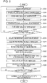
- Fig. 2 is a flowchart illustrating an exemplary process performed by the broadcast receiving apparatus 10 according to the first embodiment of the present invention. The process illustrated in Fig. 2 is performed, for example, upon switching of a power supply of the broadcast receiving apparatus 10 to ON.
- Step S202 the first receiving unit 101 starts reception of the DAB broadcast.
- the first demodulation unit 102 demodulates the digital audio signal included in the broadcast waves of the DAB broadcast received by the first receiving unit 101.
- the DAB buffer 103 stores the audio data included in the digital audio signal subjected to the demodulation by the first demodulation unit 102.
- Step S208 the second receiving unit 104 starts reception of the IP broadcast.
- the second demodulation unit 105 demodulates the digital audio signal included in the communication data about the IP broadcast received by the second receiving unit 104.
- the IP buffer 106 stores the audio data included in the digital audio signal subjected to the demodulation by the second demodulation unit 105. Practically, the processing until the audio data about the DAB broadcast is stored in the DAB buffer 103 (Steps S202 to S206) is performed in parallel with the processing until the audio data about the IP broadcast is stored in the IP buffer 106 (Steps S208 to S212).
- Step S214 the time difference calculation unit 107 determines whether the maximum amount of data is stored in the DAB buffer 103. If the time difference calculation unit 107 determines that the maximum amount of data is not stored in the DAB buffer 103 (NO in Step S214), the process goes back to Step S202 to perform the processing in Step S202 and the subsequent steps again.
- Step S216 the time difference calculation unit 107 acquires the time information added to the audio data about the DAB broadcast.
- Step S218, the time difference calculation unit 107 acquires the time information added to the audio data about the IP broadcast.
- Step S220 the time difference calculation unit 107 calculates the time difference between the time information added to the audio data about the DAB broadcast and the time information added to the audio data about the IP broadcast.
- Step S222 the comparison unit 108 sets the comparison start position at a positon after the beginning in the audio data about the DAB broadcast stored in the DAB buffer 103 on the basis of the time difference calculated in Step S220.
- Step S224 the comparison unit 108 compares the comparison target data after the comparison start position set in Step S222 with the audio data about the IP broadcast stored in the IP buffer 106 to identify the same data (link point) as the audio data about the IP broadcast stored in the IP buffer 106 from the comparison target data.
- Step S226 the delay time calculation unit 109 calculates the delay time of the IP broadcast from the DAB broadcast on the basis of the reception timing of the audio data about the IP broadcast stored in the IP buffer 106 and the reception timing of the same data identified from the comparison target data stored in the DAB buffer 103 in Step S224.
- Step S228, the delay processing unit 110 starts the delay process for the audio data about the DAB broadcast output from the output control unit 111.
- Step S230 the delay processing unit 110 determines whether the delay time of the IP broadcast calculated in Step S226 is cleared. If the delay processing unit 110 determines that the delay time of the IP broadcast is not cleared (NO in Step S230), the process performs the determination in Step S230 again.
- Step S232 the delay processing unit 110 terminates the delay process for the audio data about the DAB broadcast output from the output control unit 111. Then, the process illustrated in Fig. 2 is terminated.
- Fig. 3 illustrates exemplary processing timing by the broadcast receiving apparatus 10 according to the first embodiment of the present invention.
- the pieces of audio data having the same content [1], [2], [3], [4], ... are broadcasted in both the DAB broadcast and the IP broadcast. It is assumed here that one frame of the audio data is the audio data during a predetermined time (for example, one second) for schematic illustration.
- the IP broadcast is received with being delayed from the DAB broadcast because the IP broadcast is transmitted from a broadcasting station to the broadcast receiving apparatus via a provider, an Internet server, and so on.
- the IP broadcast is delayed from the DAB broadcast by two frames of the audio data.
- the delay process for the audio data about the DAB broadcast is performed to synchronize the output timing of the audio data about the DAB broadcast with the output timing of the audio data about the IP broadcast so that the switching from the audio output of the DAB broadcast to the audio output of the IP broadcast is seamlessly performed.
- the broadcast receiving apparatus 10 of the first embodiment sequentially stores the audio data about the DAB broadcast and the audio data about the IP broadcast, which are received, in the DAB buffer 103 and the IP buffer 106, respectively.
- the DAB buffer 103 has a capacity corresponding to six frames of the audio data and the IP buffer 106 has a capacity corresponding to one frame of the audio data.
- the example in Fig. 3 illustrates the states of the DAB buffer 103 and the IP buffer 106 at timing t2 in Fig. 3 when the audio data of six frames (the pieces of audio data [1] to [6]) is first stored in the DAB buffer 103 after the power supply of the broadcast receiving apparatus 10 is switched to ON. At this time, the piece of audio data [4] is stored in the IP buffer 106.
- the time difference calculation unit 107 calculates the time difference between the time information about the audio data about the DAB broadcast and the time information about the audio data about the IP broadcast. Then, the comparison unit 108 sets the comparison start position in the audio data stored in the DAB buffer 103 on the basis of the calculated time difference. In the example illustrated in Fig. 3 , since the time difference is about two frames of the audio data, the comparison unit 108 has enough time to set the piece of audio data [3] three frames before the pieces of audio data [6] as the comparison start position.
- the comparison unit 108 sequentially compares the pieces of audio data [3] and [4] stored in the DAB buffer 103 with the piece of audio data [4] stored in the IP buffer 106 to detect the same data as the piece of audio data [4] stored in the IP buffer 106 from the DAB buffer 103.
- the piece of audio data [4] about the DAB broadcast which is the same as the piece of audio data [4] about the IP broadcast, is detected through the second comparison.
- the delay time calculation unit 109 calculates the time difference between the reception timing of the piece of audio data [4] about the IP broadcast and the reception timing of the piece of audio data [4] about the DAB broadcast as the delay time of the IP broadcast.
- the reception of the piece of audio data [4] about the IP broadcast when the piece of audio data [6] about the DAB broadcast is received indicates that the IP broadcast is delayed from the DAB broadcast by two frames of the audio data.
- the delay processing unit 110 time-stretches the audio data about the DAB broadcast by a required number of frames (a time period from timing t3 to timing t4 in Fig. 3 ) so that the calculated delay time of the IP broadcast is cleared.
- the broadcast receiving apparatus 10 is capable of switching from the output of the DAB broadcast to the output of the IP broadcast in a state in which the output timing of the DAB broadcast is synchronized with the output timing of the IP broadcast (a state subsequent to the timing t4 in Fig. 3 ).
- the processing time to calculate the delay time of the IP broadcast is reduced by two frames of the audio data, compared with the example in the related art (refer to Fig. 11 ). Accordingly, in the example illustrated in Fig. 3 , the timing (the timing t4) when the output timing of the audio data about the DAB broadcast is synchronized with the output timing of the audio data about the IP broadcast is moved up by two frames of the audio data, compared with the example in the related art.
- the comparison process to identify the same data is started from a position closer to the same data as the audio data about the IP broadcast stored in the IP buffer 106, in the audio data about the DAB broadcast stored in the DAB buffer 103. Accordingly, the time required to perform the comparison process to identify the same data is reduced to advance the termination of the comparison process. As a result, with the broadcast receiving apparatus 10 of the first embodiment, the synchronization timing of the two broadcasts for seamless switching of the output audio is moved up.
- Fig. 4 is a block diagram illustrating an exemplary functional configuration of a broadcast receiving apparatus 10' according to the second embodiment of the present invention.
- the broadcast receiving apparatus 10' illustrated in Fig. 4 differs from the broadcast receiving apparatus 10 (refer to Fig. 1 ) of the first embodiment in that the broadcast receiving apparatus 10' includes a time difference calculation unit 107' and a comparison unit 108', instead of the time difference calculation unit 107 and the comparison unit 108.
- the time difference calculation unit 107' calculates the time difference between the time information added to the audio data about the DAB broadcast and the time information added to the audio data about the IP broadcast.
- the time difference calculation unit 107' of the second embodiment differs from the time difference calculation unit 107 of the first embodiment in that the time difference calculation unit 107' calculates the time difference without waiting for the storage of the maximum amount of audio data in the DAB buffer 103.
- the time information is added to the audio data about the DAB broadcast by the GPS 13 at constant, relatively short intervals (for example, one second).
- the time information is added to the audio data about the IP broadcast by the GPS 13 at constant, relatively long intervals (for example, two seconds). Accordingly, the time difference calculation unit 107' calculates the time difference between the two pieces of time information when the time information is added to both the audio data about the DAB broadcast and the audio data about the IP broadcast.
- the comparison unit 108' determines the audio data stored in the DAB buffer 103 at this time to be the comparison target data and compares the comparison target data with the audio data about the IP broadcast stored in the IP buffer 106 to identify the same data as the audio data about the IP broadcast stored in the IP buffer 106 from the comparison target data.
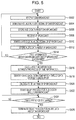
- Fig. 5 is a flowchart illustrating an exemplary process performed by the broadcast receiving apparatus 10' according to the second embodiment of the present invention. The process illustrated in Fig. 5 is performed, for example, upon switching of a power supply of the broadcast receiving apparatus 10' to ON.
- Step S502 the first receiving unit 101 starts reception of the DAB broadcast.
- the first demodulation unit 102 demodulates the digital audio signal included in the broadcast waves of the DAB broadcast received by the first receiving unit 101.
- the DAB buffer 103 stores the audio data included in the digital audio signal subjected to the demodulation by the first demodulation unit 102.
- Step S508 the second receiving unit 104 starts reception of the IP broadcast.
- the second demodulation unit 105 demodulates the digital audio signal included in the communication data about the IP broadcast received by the second receiving unit 104.
- the IP buffer 106 stores the audio data included in the digital audio signal subjected to the demodulation by the second demodulation unit 105.
- Step S514 the time difference calculation unit 107' determines whether both the time information added to the audio data about the DAB broadcast and the time information added to the audio data about the IP broadcast are acquired. If the time difference calculation unit 107' determines that both the time information about the DAB broadcast and the time information about the IP broadcast are not acquired (NO in Step S514), the process goes back to Step S502 to perform the processing in Step S502 and the subsequent steps again.
- Step S516 the time difference calculation unit 107' calculates the time difference between the time information about the DAB broadcast and the time information about the IP broadcast, which are acquired.
- the comparison unit 108' uses the audio data stored in the DAB buffer 103 at the time when the time difference is calculated as the comparison target data and compares the comparison target data with the audio data about the IP broadcast stored in the IP buffer 106 to identify the same data (link point) as the audio data about the IP broadcast stored in the IP buffer 106 from the comparison target data.
- Step S520 the delay time calculation unit 109 calculates the delay time of the IP broadcast from the DAB broadcast on the basis of the reception timing of the audio data about the IP broadcast stored in the IP buffer 106 and the reception timing of the same data identified from the comparison target data stored in the DAB buffer 103 in Step S518.
- Step S522 the delay processing unit 110 starts the delay process for the audio data about the DAB broadcast output from the output control unit 111.
- Step S524 the delay processing unit 110 determines whether the delay time of the IP broadcast calculated in Step S520 is cleared. If the delay processing unit 110 determines that the delay time of the IP broadcast is not cleared (NO in Step S524), the process performs the determination in Step S524 again.
- Step S526 the delay processing unit 110 terminates the delay process for the audio data about the DAB broadcast output from the output control unit 111. Then, the process illustrated in Fig. 5 is terminated.
- Fig. 6 illustrates exemplary processing timing by the broadcast receiving apparatus 10' according to the second embodiment of the present invention. Since the content and the reception timing of the audio data about the DAB broadcast and the content and the reception timing of the audio data about the IP broadcast in Fig. 6 are the same as those in the first embodiment (refer to Fig. 3 ), a description of them is omitted herein.
- the broadcast receiving apparatus 10' of the second embodiment sequentially stores the audio data about the DAB broadcast and the audio data about the IP broadcast, which are received, in the DAB buffer 103 and the IP buffer 106, respectively.
- the DAB buffer 103 has a capacity corresponding to six frames of the audio data and the IP buffer 106 has a capacity corresponding to one frame of the audio data.
- the example in Fig. 6 illustrates the states of the DAB buffer 103 and the IP buffer 106 at timing t2 in Fig. 6 when the audio data of four frames (the pieces of audio data [1] to [4]) is first stored in the DAB buffer 103 after the power supply of the broadcast receiving apparatus 10' is switched to ON. At this time, the piece of audio data [2] is stored in the IP buffer 106.
- the time difference calculation unit 107' calculates here the time difference between the time information added to the audio data about the DAB broadcast and the time information added to the audio data about the IP broadcast.
- the time information is added to the audio data about the DAB broadcast at constant, relatively short intervals (for every one frame) while the time information is added to the audio data about the IP broadcast at constant, relatively long intervals (for example, for every two frames).
- the time difference calculation unit 107' calculates the time difference between the two pieces of time information at the timing when the time information is added to both the audio data about the DAB broadcast and the audio data about the IP broadcast.
- the comparison unit 108' uses the pieces of audio data [1] to [4] stored in the DAB buffer 103 as the comparison target data and starts the process of identifying the same data as the piece of audio data [2] stored in the IP buffer 106 from the comparison target data. Specifically, the comparison unit 108' sequentially compares the pieces of audio data [1] and [2] stored in the DAB buffer 103 with the piece of audio data [2] stored in the IP buffer 106 to detect the same data as the piece of audio data [2] stored in the IP buffer 106 from the DAB buffer 103. In other words, in the example in Fig. 6 , the piece of audio data [2] about the DAB broadcast, which is the same as the piece of audio data [2] about the IP broadcast, is detected through the second comparison.
- the delay time calculation unit 109 calculates the time difference between the reception timing of the piece of audio data [2] about the IP broadcast and the reception timing of the piece of audio data [2] about the DAB broadcast as the delay time of the IP broadcast.
- the reception of the piece of audio data [2] about the IP broadcast when the piece of audio data [4] about the DAB broadcast is received indicates that the IP broadcast is delayed from the DAB broadcast by two frames of the audio data.
- the delay processing unit 110 time-stretches the audio data about the DAB broadcast by a required number of frames (a time period from timing t3 to timing t4 in Fig. 6 ) so that the calculated delay time of the IP broadcast is cleared.
- the broadcast receiving apparatus 10' is capable of switching from the output of the DAB broadcast to the output of the IP broadcast in a state in which the output timing of the DAB broadcast is synchronized with the output timing of the IP broadcast (a state subsequent to the timing t4 in Fig. 6 ).
- the processing time to calculate the delay time of the IP broadcast is reduced by two frames of the audio data, compared with the example in the related art (refer to Fig. 11 ).
- the timing when the calculation of the delay time of the IP broadcast is started is moved up by two frames of the audio data, compared with the example in the related art.
- the timing (the timing t4 in Fig. 6 ) when the output timing of the audio data about the DAB broadcast is synchronized with the output timing of the audio data about the IP broadcast is moved up by four frames of the audio data, compared with the example in the related art.
- the comparison process for identifying the same data as the audio data about the IP broadcast stored in the IP buffer 106 from the audio data about the DAB broadcast stored in the DAB buffer 103 is started without waiting for the storage of the maximum amount of audio data in the DAB buffer 103.
- the timing when the comparison process is started is moved up, the same data to be identified from the DAB buffer 103 is made closer to the beginning of the DAB buffer 103 (that is, the position where the comparison process is started). Accordingly, the timing when the comparison process for identifying the same data is started is moved up and the time required for the comparison process is reduced, thereby advancing the termination of the comparison process.
- the synchronization timing of the two broadcasts for seamless switching of the output audio is moved up.
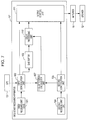
- Fig. 7 is a block diagram illustrating an exemplary functional configuration of a broadcast receiving apparatus 10'' according to the third embodiment of the present invention.
- the broadcast receiving apparatus 10'' illustrated in Fig. 7 differs from the broadcast receiving apparatus 10 (refer to Fig. 1 ) of the first embodiment in that the broadcast receiving apparatus 10'' includes a time difference calculation unit 107' and a delay processing unit 110', instead of the time difference calculation unit 107 and the delay processing unit 110, and in that the broadcast receiving apparatus 10'' does not include the IP buffer 106, the comparison unit 108, and the delay time calculation unit 109.
- the time difference calculation unit 107' of the third embodiment is equivalent to the time difference calculation unit 107' of the second embodiment and calculates the time difference without waiting for the storage of the maximum amount of audio data in the DAB buffer 103.
- the delay processing unit 110' performs the delay process for the audio data about the DAB broadcast in accordance with the time difference calculated by the time difference calculation unit 107'. Specifically, upon calculation of the time difference by the time difference calculation unit 107', the delay processing unit 110' immediately starts the delay process for the audio data about the DAB broadcast. This allows the delay processing unit 110' to synchronize the output timing of the audio data about the DAB broadcast output from the output control unit 111 with the output timing of the audio data about the IP broadcast output from the output control unit 111.
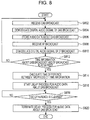
- Fig. 8 is a flowchart illustrating an exemplary process performed by the broadcast receiving apparatus 10'' according to the third embodiment of the present invention. The process illustrated in Fig. 8 is performed, for example, upon switching of a power supply of the broadcast receiving apparatus 10'' to ON.
- Step S802 the first receiving unit 101 starts reception of the DAB broadcast.
- the first demodulation unit 102 demodulates the digital audio signal included in the broadcast waves of the DAB broadcast received by the first receiving unit 101.
- the DAB buffer 103 stores the audio data included in the digital audio signal subjected to the demodulation by the first demodulation unit 102.
- Step S808 the second receiving unit 104 starts reception of the IP broadcast.
- the second demodulation unit 105 demodulates the digital audio signal included in the communication data about the IP broadcast received by the second receiving unit 104.
- Step S812 the time difference calculation unit 107' determines whether both the time information added to the audio data about the DAB broadcast and the time information added to the audio data about the IP broadcast are acquired. If the time difference calculation unit 107' determines that both the time information about the DAB broadcast and the time information about the IP broadcast are not acquired (NO in Step S812), the process goes back to Step S802 to perform the processing in Step S802 and the subsequent steps again.
- Step S814 the time difference calculation unit 107' calculates the time difference between the time information about the DAB broadcast and the time information about the IP broadcast, which are acquired.
- Step S816 the delay processing unit 110' starts the delay process for the audio data about the DAB broadcast output from the output control unit 111.
- Step S818 the delay processing unit 110' determines whether the time difference calculated in Step S814 is cleared. If the delay processing unit 110' determines that the time difference calculated in Step S814 is not cleared (NO in Step S818), the process performs the determination in Step S818 again.
- Step S820 the delay processing unit 110' terminates the delay process for the audio data about the DAB broadcast output from the output control unit 111. Then, the process illustrated in Fig. 8 is terminated.
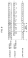
- Fig. 9 illustrates exemplary processing timing by the broadcast receiving apparatus 10'' according to the third embodiment of the present invention. Since the content and the reception timing of the audio data about the DAB broadcast and the content and the reception timing of the audio data about the IP broadcast in Fig. 9 are the same as those in the first embodiment (refer to Fig. 3 ), a description of them is omitted herein.
- the time difference calculation unit 107' upon turning on of the power supply of the broadcast receiving apparatus 10'' (timing t1 in Fig. 9 ) and reception of the audio data about the DAB broadcast and the audio data about the IP broadcast, the time difference calculation unit 107' attempts to acquire the time information from each of the DAB broadcast and the IP broadcast. Upon acquisition of the time information from each of the DAB broadcast and the IP broadcast, the time difference calculation unit 107' calculates the time difference between the time information acquired from the DAB broadcast and the time information acquired from the IP broadcast.
- the time information (denoted by "T" in Fig. 9 ) is acquired from each of the DAB broadcast and the IP broadcast and the time difference between the two pieces of time information is calculated (the timing t2 in Fig. 9 ).
- about two frames of the audio data are calculated as the time difference between the two pieces of time information.
- the delay processing unit 110' Upon calculation of the time difference in the above manner, the delay processing unit 110' immediately starts the delay process for the audio data about the DAB broadcast. Specifically, the delay processing unit 110' time-stretches the audio data about the DAB broadcast by a required number of frames (a time period from the timing t2 to timing t3 in Fig. 9 ) so that the calculated time difference is cleared. This allows the broadcast receiving apparatus 10'' to clear the delay time of the IP broadcast. As a result, the broadcast receiving apparatus 10'' is capable of switching from the output of the DAB broadcast to the output of the IP broadcast in a state in which the output timing of the DAB broadcast is synchronized with the output timing of the IP broadcast (a state subsequent to the timing t3 in Fig. 9 ).
- the delay process for the DAB broadcast is performed on the basis of the time difference between the time information about the DAB broadcast and the time information about the IP broadcast without performing the comparison process (the process of calculating the time difference) described above in the first and second embodiments. Accordingly, in the example illustrated in Fig. 9 , the timing (the timing t3 in Fig. 9 ) when the output timing of the audio data about the DAB broadcast is synchronized with the output timing of the audio data about the IP broadcast is moved up by six frames of the audio data, compared with the example in the related art.
- the broadcast receiving apparatus 10'' of the third embodiment upon calculation of the time difference between the time information about the audio data about the DAB broadcast and the time information about the audio data about the IP broadcast, the delay process for the audio data about the DAB broadcast is immediately started, regarding the time difference as the delay time of the IP broadcast.
- the broadcast receiving apparatus 10'' of the third embodiment the synchronization timing of the two broadcasts for seamless switching of the output audio is moved up.
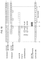
- a fourth embodiment of the present invention will now be described with reference to Fig. 10 .
- the first embodiment and the second embodiment described above are combined with each other in the fourth embodiment.
- the configuration in which the comparison process is started at the time when the time difference between the time information about the DAB broadcast and the time information about the IP broadcast is calculated without waiting for the storage of the maximum amount of audio data in the DAB buffer 103 is combined with the configuration in which the comparison start position is set at a position after the beginning in the audio data stored in the DAB buffer 103 on the basis of the calculated time difference.
- the DAB buffer has a capacity corresponding to 15 frames of the audio data.
- the IP broadcast is delayed from the DAB broadcast by four frames of the audio data.
- the time information is added to the audio data about the DAB broadcast for every one frame of the audio data and the time information is added to the audio data about the IP broadcast for every four frames of the audio data.
- Fig. 10 illustrates the states of the DAB buffer and the IP buffer at timing t2 in Fig. 10 when the audio data of eight frames (the pieces of audio data [1] to [8]) is first stored in the DAB buffer after a power supply of the broadcast receiving apparatus is switched to ON. At this time, the piece of audio data [4] is stored in the IP buffer.
- the time information is added to the piece of audio data [8] about the DAB broadcast and the time information is added also to the piece of audio data [4] about the IP broadcast. Accordingly, the broadcast receiving apparatus calculates the time difference between the time information acquired from the DAB broadcast and the time information acquired from the IP broadcast at this time.
- the broadcast receiving apparatus sets the comparison start position in the audio data stored in the DAB buffer on the basis of the calculated time difference.
- the broadcast receiving apparatus since the calculated time difference is about four frames of the audio data, the broadcast receiving apparatus has enough time to set the piece of audio data [3] five frames before the piece of audio data [8] as the comparison start position.
- the broadcast receiving apparatus sequentially compares the pieces of audio data [3] and [4] stored in the DAB buffer with the piece of audio data [4] stored in the IP buffer to detect the same data as the piece of audio data [4] stored in the IP buffer from the DAB buffer.
- the piece of audio data [4] about the DAB broadcast which is the same as the piece of audio data [4] about the IP broadcast, is detected through the second comparison.
- the broadcast receiving apparatus calculates the time difference between the reception timing of the piece of audio data [4] about the IP broadcast and the reception timing of the piece of audio data [4] about the DAB broadcast as the delay time of the IP broadcast.
- the reception of the piece of audio data [4] about the IP broadcast when the piece of audio data [8] about the DAB broadcast is received indicates that the IP broadcast is delayed from the DAB broadcast by four frames of the audio data.
- the broadcast receiving apparatus time-stretches the audio data about the DAB broadcast by a required number of frames (a time period from timing t3 to timing t4 in Fig. 10 ) so that the calculated delay time of the IP broadcast is cleared. This allows the broadcast receiving apparatus to clear the delay time of the IP broadcast. As a result, the broadcast receiving apparatus is capable of switching from the output of the DAB broadcast to the output of the IP broadcast in a state in which the output timing of the DAB broadcast is synchronized with the output timing of the IP broadcast (a state subsequent to the timing t4 in Fig. 10 ).
- the comparison process is started at the time when eight frames of the audio data, which is less than the maximum amount of data (15 frames), are stored in the DAB buffer. Accordingly, the timing when the comparison process is started is moved up by seven frames of the audio data, compared with the method in the related art in which the comparison process is started at the time when the maximum amount of audio data is stored in the DAB buffer.
- the comparison process is started from the piece of audio data [3] stored in the DAB buffer on the basis of the calculated time difference. Accordingly, the processing time to calculate the delay time of the IP broadcast is reduced by two frames of the audio data, compared with the method in the related art in which the comparison process is started from the beginning (the piece of audio data [1]).
- the broadcast receiving apparatus of the fourth embodiment the synchronization timing of the two broadcasts for seamless switching of the output audio is greatly moved up, compared with the method in the related art.
- the DAB broadcast is applied as the first standard broadcast and the IP broadcast is applied as the second standard broadcast in the first to fourth embodiments described above, the present invention is not limited to these.
- a frequency modulation (FM) broadcast may be applied as the first standard broadcast and the IP broadcast may be applied as the second standard broadcast.
- the DAB broadcast may be applied as the first standard broadcast and the FM broadcast may be applied as the second standard broadcast.
Landscapes
- Engineering & Computer Science (AREA)
- Signal Processing (AREA)
- Circuits Of Receivers In General (AREA)
- Two-Way Televisions, Distribution Of Moving Picture Or The Like (AREA)
Abstract
Description
- The present invention relates to a broadcast receiving apparatus and an output control method. In particular, the present invention is preferably used for a broadcast receiving apparatus and an output control method capable of switching between a first standard broadcast and a second standard broadcast delayed from the first specification broadcast and selectively outputting the first standard broadcast or the second standard broadcast.
- Broadcast receiving apparatuses have heretofore been proposed, which receive two broadcasts (for example, a digital audio broadcasting (DAB) broadcast and an Internet protocol (IP) broadcast) conforming to different standards but having the same content and switch between the two broadcasts to selectively output either of the broadcasts. With such an apparatus, for example, when the reception environment of one broadcast is degraded, switching to the other broadcast and outputting the other broadcast allows a user to continuously listen to the broadcast of the same content.
- However, there are cases in which a time difference occurs between two broadcasts received by such a broadcast receiving apparatus. For example, in a broadcast receiving apparatus capable of switching between the DAB broadcast and the IP broadcast and selectively outputting the DAB broadcast or the IP broadcast, the IP broadcast is transmitted from a broadcasting station to the broadcast receiving apparatus via a provider, an Internet server, and so on. Accordingly, it is known that the time difference occurs between the DAB broadcast and the IP broadcast received by the broadcast receiving apparatus, that is, the reception of the IP broadcast is delayed from the reception of the DAB broadcast.
- In order to resolve the above problem, technologies are proposed, which clear the time difference between the two broadcasts and synchronize the output timing of one broadcast with the output timing of the other broadcast to enable seamless switching between the two broadcasts.
- For example,
JP 2008-227599 A - In order to calculate the time difference between two broadcasts for the synchronization between the output timing of one broadcast and the output timing of the other broadcast, a method of storing the respective pieces of broadcast data about the two broadcasts in buffers, identifying the same data as the other piece of broadcast data from one piece of broadcast data, and calculating the time difference between the reception timing of the same data identified from the one piece of broadcast data and the reception timing of the other piece of broadcast data has heretofore been used. However, this method has a problem in that it takes a long time to calculate the time difference.
-
Fig. 11 illustrates exemplary processing timing by a broadcast receiving apparatus in the related art. The broadcast receiving apparatus in the related art is exemplified here, which is capable of switching of output audio between the DAB broadcast and the IP broadcast. In this example, pieces of audio data having the same content "1" "2", "3" "4" ... are broadcasted in both the DAB broadcast and the IP broadcast. It is assumed here that one frame of the audio data is the broadcast data during a predetermined time (for example, one second) for schematic illustration. - As illustrated in
Fig. 11 , although the audio data about the DAB broadcast has the same content as that of the audio data about the IP broadcast, the IP broadcast is received with being delayed from the DAB broadcast because the IP broadcast is transmitted from a broadcasting station to the broadcast receiving apparatus via a provider, an Internet server, and so on. In the example illustrated inFig. 11 , the IP broadcast is delayed from the DAB broadcast by two frames of the audio data. - Accordingly, in the example illustrated in
Fig. 11 , a delay process for the audio data about the DAB broadcast is performed to synchronize the output timing of the audio data about the DAB broadcast with the output timing of the audio data about the IP broadcast so that the switching from the audio output of the DAB broadcast to the audio output of the IP broadcast is seamlessly performed. - Specifically, the broadcast receiving apparatus first detects the same data (link point) as the audio data about the IP broadcast stored in an IP buffer from the audio data about the DAB broadcast stored in a DAB buffer. Here, the broadcast receiving apparatus sequentially searches the pieces of audio data about the DAB broadcast stored in the DAB buffer from the beginning for the same data as the audio data about the IP broadcast.
- For example, in the example illustrated in
Fig. 11 , upon turning on of a power supply of the broadcast receiving apparatus (timing t1 inFig. 11 ) and reception of the audio data about the DAB broadcast and the audio data about the IP broadcast, the audio data about the DAB broadcast and the audio data about the IP broadcast, which are received, are sequentially stored in the respective buffers. In the example illustrated inFig. 11 , the DAB buffer has a capacity corresponding to six frames of the audio data and the IP buffer has a capacity corresponding to one frame of the audio data. Upon reception of next new data when the maximum amount of audio data is stored in each buffer, the oldest data is deleted from the buffer and the next new data is stored in the buffer. - The example in
Fig. 11 illustrates the states of the DAB buffer and the IP buffer at timing t2 inFig. 11 when the audio data of six frames is first stored in the DAB buffer after the power supply of the broadcast receiving apparatus is switched to ON. At this time, the pieces of audio data [1] to [6] are stored in the DAB buffer and the piece of audio data [4] is stored in the IP buffer. - Upon storage of the maximum amount of audio data in each buffer, first, the broadcast receiving apparatus in the related art sequentially compares the pieces of audio data [1], [2], [3], and [4] stored in the DAB buffer with the piece of audio data [4] stored in the IP buffer to detect the same data as the piece of audio data [4] stored in the IP buffer from the DAB buffer. In other words, in the example in
Fig. 11 , the piece of audio data [4] about the DAB broadcast, which is the same as the piece of audio data [4] about the IP broadcast, is detected through the fourth comparison. - Then, the broadcast receiving apparatus in the related art calculates the time difference between the reception timing of the piece of audio data [4] about the IP broadcast and the reception timing of the piece of audio data [4] about the DAB broadcast as a delay time of the IP broadcast. The reception of the piece of audio data [4] about the IP broadcast when the piece of audio data [6] about the DAB broadcast is received indicates that the IP broadcast is delayed from the DAB broadcast by two frames of the audio data. In the example illustrated in
Fig. 11 , since the comparison process has been performed four times, it takes a processing time (a time period from the timing t2 to timing t3 inFig. 11 ) corresponding to four frames of the audio data before the delay time of the IP broadcast is calculated. - Then, the broadcast receiving apparatus time-stretches the audio data about the DAB broadcast by a required number of frames (a time period from the timing t3 to timing t4 in
Fig. 11 ) so that the calculated delay time of the IP broadcast is cleared. The time-stretch means that the frequency of a playback process is reduced to lengthen a playback time. This allows the broadcast receiving apparatus in the related art to clear the delay time of the IP broadcast. As a result, the broadcast receiving apparatus in the related art is capable of switching from the output of the DAB broadcast to the output of the IP broadcast in a state in which the output timing of the DAB broadcast is synchronized with the output timing of the IP broadcast (a state subsequent to the timing t4 inFig. 11 ). - As described above, the broadcast receiving apparatus in the related art has a problem in that, since it takes a long time to calculate the delay time for the seamless switching of the output audio, the synchronization timing of the two broadcasts for seamless switching of the output audio is not moved up. Accordingly, when the switching to the IP broadcast is required because, for example, the reception environment of the DAB broadcast is degraded immediately after the power supply of the broadcast receiving apparatus is switched to ON, it takes a time to switch to the IP broadcast and the user is forced to listen to the output audio of the DAB broadcast.
- Although the amount of data to be stored in the DAB buffer is set to the audio data of six frames (when one frame corresponds to one second, the amount of data corresponds to six seconds) in the example illustrated in
Fig. 11 , it may be necessary to store a larger amount of data in the DAB buffer. For example, when it is necessary to store the audio data corresponding to 60 seconds in the DAB buffer, the comparison process is started only after at least 60 seconds and the number of times of the comparison process is greatly increased.
It is an object of the present invention to move up the synchronization timing of two broadcasts for seamless switching of output audio. - The present invention relates to a broadcast receiving apparatus and a method according to the independent claims. Embodiments are disclosed in the dependent claims. The present invention according to an aspect provides a broadcast receiving apparatus that compares first standard broadcast data stored in a first storage unit with second standard broadcast data stored in a second storage unit to identify the same data as the second standard broadcast data stored in the second storage unit from the first standard broadcast data stored in the first storage unit; calculates a delay time of a second standard broadcast from a first standard broadcast on the basis of reception timing of the same data identified from the first standard broadcast data stored in the first storage unit and reception timing of the second standard broadcast data stored in the second storage unit; and performs a delay process to the first standard broadcast data in accordance with the calculated delay time to synchronize output timing of the first standard broadcast data with output timing of the second standard broadcast data. The broadcast receiving apparatus calculates a time difference between time information added to the first standard broadcast data and time information added to the second standard broadcast data, determines the broadcast data stored in a partial range of the first storage unit to be comparison target data on the basis of the calculated time difference, and performs the comparison to the comparison target data to identify the same data as the second standard broadcast data stored in the second storage unit from the comparison target data.
- According to an embodiment of the present invention, the range of data to be compared is narrowed down through the calculation of the time difference in the first standard broadcast data stored in the first storage unit. Accordingly, it is possible to advance termination of the process of identifying the same data from the first standard broadcast data. Consequently, it is possible to move up the synchronization timing of the two broadcasts for seamless switching of output audio.
-
-
Fig. 1 is a block diagram illustrating an exemplary functional configuration of a broadcast receiving apparatus according to a first embodiment of the present invention; -
Fig. 2 is a flowchart illustrating an exemplary process performed by the broadcast receiving apparatus according to the first embodiment of the present invention; -
Fig. 3 illustrates exemplary processing timing by the broadcast receiving apparatus according to the first embodiment of the present invention; -
Fig. 4 is a block diagram illustrating an exemplary functional configuration of a broadcast receiving apparatus according to a second embodiment of the present invention; -
Fig. 5 is a flowchart illustrating an exemplary process performed by the broadcast receiving apparatus according to the second embodiment of the present invention; -
Fig. 6 illustrates exemplary processing timing by the broadcast receiving apparatus according to the second embodiment of the present invention; -
Fig. 7 is a block diagram illustrating an exemplary functional configuration of a broadcast receiving apparatus according to a third embodiment of the present invention; -
Fig. 8 is a flowchart illustrating an exemplary process performed by the broadcast receiving apparatus according to the third embodiment of the present invention; -
Fig. 9 illustrates exemplary processing timing by the broadcast receiving apparatus according to the third embodiment of the present invention; -
Fig. 10 illustrates exemplary processing timing by a broadcast receiving apparatus according to a fourth embodiment of the present invention; and -
Fig. 11 illustrates exemplary processing timing by a broadcast receiving apparatus in the related art. - Embodiments of the present invention will herein be described with reference to the attached drawings.
Fig. 1 is a block diagram illustrating an exemplary functional configuration of abroadcast receiving apparatus 10 according to a first embodiment of the present invention. Thebroadcast receiving apparatus 10 illustrated inFig. 1 is capable of receiving the DAB broadcast (an example of a first standard broadcast) and the IP broadcast (an example of a second standard broadcast) and switching between the audio of the received DAB broadcast and the audio of the received IP broadcast to selectively output the audio of the DAB broadcast or the audio of the IP broadcast to aspeaker 12. - Referring to
Fig. 1 , thebroadcast receiving apparatus 10 includes afirst receiving unit 101, afirst demodulation unit 102, aDAB buffer 103, asecond receiving unit 104, asecond demodulation unit 105, anIP buffer 106, a timedifference calculation unit 107, acomparison unit 108, a delaytime calculation unit 109, adelay processing unit 110, and anoutput control unit 111. - Each of the above
functional blocks 101 to 111 may be configured by any of hardware, a digital signal processor (DSP), and software. For example, when the abovefunctional blocks 101 to 111 are configured by software, thefunctional blocks 101 to 111 practically include a central processing unit (CPU), a random access memory (RAM), a read only memory (ROM), and so on in a computer and are realized by running programs. The programs are stored in a storage medium, such as the RAM, the ROM, a hard disk, or a semiconductor memory. - The
first receiving unit 101 receives broadcast waves of the DAB broadcast. Thefirst demodulation unit 102 demodulates a digital audio signal included in the broadcast waves of the DAB broadcast received by thefirst receiving unit 101. The DAB buffer 103 (first storage unit) stores audio data included in the DAB broadcast (the DAB broadcast subjected to the demodulation by the first demodulation unit 102) received by thefirst receiving unit 101. The maximum amount of audio data about the DAB broadcast capable of being stored in theDAB buffer 103 is set in advance. - The
second receiving unit 104 receives communication data about the IP broadcast. Thesecond demodulation unit 105 demodulates a digital audio signal included in the communication data about the IP broadcast received by thesecond receiving unit 104. The IP buffer 106 (second storage unit) stores audio data included in the IP broadcast (the IP broadcast subjected to the demodulation by the second demodulation unit 105) received by thesecond receiving unit 104. The maximum amount of audio data about the IP broadcast capable of being stored in theIP buffer 106 is set in advance. - The IP broadcast received by the
second receiving unit 104 has the same content as that of the DAB broadcast received by thefirst receiving unit 101. However, the IP broadcast received by thesecond receiving unit 104 is received with being delayed from the DAB broadcast received by thefirst receiving unit 101. This is because thefirst receiving unit 101 directly receives the broadcast waves of the DAB broadcast while thesecond receiving unit 104 receives the communication data about the IP broadcast transmitted from a broadcasting station via a provider, an Internet server, and so on. - The
output control unit 111 switches between the digital audio signal of the DAB broadcast (the DAB broadcast subjected to the demodulation by the first demodulation unit 102) received by thefirst receiving unit 101 and the digital audio signal of the IP broadcast (the IP broadcast subjected to the demodulation by the second demodulation unit 105) received by thesecond receiving unit 104 and selectively outputs the digital audio signal of the DAB broadcast or the digital audio signal of the IP broadcast. For example, theoutput control unit 111 switches to and outputs the DAB broadcast when the reception signal strength of the DAB broadcast is higher than a predetermined threshold value. In contrast, theoutput control unit 111 switches to and outputs the IP broadcast when the reception signal strength of the DAB broadcast is lower than the predetermined threshold value. In other words, theoutput control unit 111 preferentially outputs the DAB broadcast having a quality higher than that of the IP broadcast. The audio signal output from theoutput control unit 111 is amplified by anamplifier 11 and the audio is output from thespeaker 12. - The time
difference calculation unit 107 calculates a time difference between time information added to the audio data about the DAB broadcast and time information added to the audio data about the IP broadcast. The time information has already been added to the audio data about the IP broadcast when the audio data about the IP broadcast is received by thesecond receiving unit 104. In contrast, the time information supplied from a Global Positioning System (GPS) 13 is added to the audio data about the DAB broadcast when the audio data about the DAB broadcast is received by thefirst receiving unit 101. - The
comparison unit 108 compares the audio data about the DAB broadcast stored in theDAB buffer 103 with the audio data about the IP broadcast stored in theIP buffer 106 to identify the same data as the audio data about the IP broadcast stored in theIP buffer 106 from the audio data about the DAB broadcast stored in theDAB buffer 103. - In the first embodiment, the
comparison unit 108 determines the audio data stored in a partial range of theDAB buffer 103 to be comparison target data on the basis of the time difference calculated by the timedifference calculation unit 107. Then, thecomparison unit 108 compares the comparison target data with the audio data about the IP broadcast stored in theIP buffer 106 to identify the same data as the audio data about the IP broadcast stored in theIP buffer 106 from the comparison target data. - Specifically, in the first embodiment, the
comparison unit 108 sets a comparison start position at a positon after the beginning in the audio data about the DAB broadcast stored in theDAB buffer 103 on the basis of the time difference calculated by the timedifference calculation unit 107 and determines the data after the comparison start position to be the comparison target data. Then, thecomparison unit 108 compares the comparison target data with the audio data about the IP broadcast stored in theIP buffer 106 to identify the same data as the audio data about the IP broadcast stored in theIP buffer 106 from the comparison target data. - The delay
time calculation unit 109 calculates a delay time of the IP broadcast from the DAB broadcast on the basis of the reception timing of the same data identified by thecomparison unit 108 from the audio data about the DAB broadcast stored in theDAB buffer 103 and the reception timing of the audio data about the IP broadcast stored in theIP buffer 106. For example, when the reception timing of the same data identified from the audio data about the DAB broadcast stored in theDAB buffer 103 is two seconds before the reception timing of the audio data about the IP broadcast stored in theIP buffer 106, the delaytime calculation unit 109 calculates the delay time of the IP broadcast from the DAB broadcast as "two seconds." - The
delay processing unit 110 performs a delay process (time-stretching) to the audio data about the DAB broadcast in accordance with the delay time calculated by the delaytime calculation unit 109. Thedelay processing unit 110 synchronizes the output timing of the audio data about the DAB broadcast output from theoutput control unit 111 with the output timing of the audio data about the IP broadcast output from theoutput control unit 111 through the delay process (time-stretching). -
Fig. 2 is a flowchart illustrating an exemplary process performed by thebroadcast receiving apparatus 10 according to the first embodiment of the present invention. The process illustrated inFig. 2 is performed, for example, upon switching of a power supply of thebroadcast receiving apparatus 10 to ON. - Referring to
Fig. 2 , in Step S202, thefirst receiving unit 101 starts reception of the DAB broadcast. In Step S204, thefirst demodulation unit 102 demodulates the digital audio signal included in the broadcast waves of the DAB broadcast received by thefirst receiving unit 101. In Step S206, theDAB buffer 103 stores the audio data included in the digital audio signal subjected to the demodulation by thefirst demodulation unit 102. - In Step S208, the
second receiving unit 104 starts reception of the IP broadcast. In Step S210, thesecond demodulation unit 105 demodulates the digital audio signal included in the communication data about the IP broadcast received by thesecond receiving unit 104. In Step S212, theIP buffer 106 stores the audio data included in the digital audio signal subjected to the demodulation by thesecond demodulation unit 105. Practically, the processing until the audio data about the DAB broadcast is stored in the DAB buffer 103 (Steps S202 to S206) is performed in parallel with the processing until the audio data about the IP broadcast is stored in the IP buffer 106 (Steps S208 to S212). - In Step S214, the time
difference calculation unit 107 determines whether the maximum amount of data is stored in theDAB buffer 103. If the timedifference calculation unit 107 determines that the maximum amount of data is not stored in the DAB buffer 103 (NO in Step S214), the process goes back to Step S202 to perform the processing in Step S202 and the subsequent steps again. - If the time
difference calculation unit 107 determines that the maximum amount of data is stored in the DAB buffer 103 (YES in Step S214), in Step S216, the timedifference calculation unit 107 acquires the time information added to the audio data about the DAB broadcast. In Step S218, the timedifference calculation unit 107 acquires the time information added to the audio data about the IP broadcast. In Step S220, the timedifference calculation unit 107 calculates the time difference between the time information added to the audio data about the DAB broadcast and the time information added to the audio data about the IP broadcast. - In Step S222, the
comparison unit 108 sets the comparison start position at a positon after the beginning in the audio data about the DAB broadcast stored in theDAB buffer 103 on the basis of the time difference calculated in Step S220. In Step S224, thecomparison unit 108 compares the comparison target data after the comparison start position set in Step S222 with the audio data about the IP broadcast stored in theIP buffer 106 to identify the same data (link point) as the audio data about the IP broadcast stored in theIP buffer 106 from the comparison target data. - In Step S226, the delay
time calculation unit 109 calculates the delay time of the IP broadcast from the DAB broadcast on the basis of the reception timing of the audio data about the IP broadcast stored in theIP buffer 106 and the reception timing of the same data identified from the comparison target data stored in theDAB buffer 103 in Step S224. In Step S228, thedelay processing unit 110 starts the delay process for the audio data about the DAB broadcast output from theoutput control unit 111. - In Step S230, the
delay processing unit 110 determines whether the delay time of the IP broadcast calculated in Step S226 is cleared. If thedelay processing unit 110 determines that the delay time of the IP broadcast is not cleared (NO in Step S230), the process performs the determination in Step S230 again. - If the
delay processing unit 110 determines that the delay time of the IP broadcast is cleared (YES in Step S230), in Step S232, thedelay processing unit 110 terminates the delay process for the audio data about the DAB broadcast output from theoutput control unit 111. Then, the process illustrated inFig. 2 is terminated. -
Fig. 3 illustrates exemplary processing timing by thebroadcast receiving apparatus 10 according to the first embodiment of the present invention. In the example illustrated inFig. 3 , the pieces of audio data having the same content [1], [2], [3], [4], ... are broadcasted in both the DAB broadcast and the IP broadcast. It is assumed here that one frame of the audio data is the audio data during a predetermined time (for example, one second) for schematic illustration. - As illustrated in
Fig. 3 , although the audio data about the DAB broadcast has the same content as that of the audio data about the IP broadcast, the IP broadcast is received with being delayed from the DAB broadcast because the IP broadcast is transmitted from a broadcasting station to the broadcast receiving apparatus via a provider, an Internet server, and so on. In the example illustrated inFig. 3 , the IP broadcast is delayed from the DAB broadcast by two frames of the audio data. - Accordingly, in the example illustrated in
Fig. 3 , the delay process for the audio data about the DAB broadcast is performed to synchronize the output timing of the audio data about the DAB broadcast with the output timing of the audio data about the IP broadcast so that the switching from the audio output of the DAB broadcast to the audio output of the IP broadcast is seamlessly performed. - Specifically, upon turning on of the power supply of the broadcast receiving apparatus 10 (timing t1 in
Fig. 3 ) and reception of the audio data about the DAB broadcast and the audio data about the IP broadcast, thebroadcast receiving apparatus 10 of the first embodiment sequentially stores the audio data about the DAB broadcast and the audio data about the IP broadcast, which are received, in theDAB buffer 103 and theIP buffer 106, respectively. - In the example illustrated in
Fig. 3 , theDAB buffer 103 has a capacity corresponding to six frames of the audio data and theIP buffer 106 has a capacity corresponding to one frame of the audio data. The example inFig. 3 illustrates the states of theDAB buffer 103 and theIP buffer 106 at timing t2 inFig. 3 when the audio data of six frames (the pieces of audio data [1] to [6]) is first stored in theDAB buffer 103 after the power supply of thebroadcast receiving apparatus 10 is switched to ON. At this time, the piece of audio data [4] is stored in theIP buffer 106. - After the maximum amount (six frames) of audio data is stored in the
DAB buffer 103, first, the timedifference calculation unit 107 calculates the time difference between the time information about the audio data about the DAB broadcast and the time information about the audio data about the IP broadcast. Then, thecomparison unit 108 sets the comparison start position in the audio data stored in theDAB buffer 103 on the basis of the calculated time difference. In the example illustrated inFig. 3 , since the time difference is about two frames of the audio data, thecomparison unit 108 has enough time to set the piece of audio data [3] three frames before the pieces of audio data [6] as the comparison start position. - Then, the
comparison unit 108 sequentially compares the pieces of audio data [3] and [4] stored in theDAB buffer 103 with the piece of audio data [4] stored in theIP buffer 106 to detect the same data as the piece of audio data [4] stored in theIP buffer 106 from theDAB buffer 103. In other words, in the example inFig. 3 , the piece of audio data [4] about the DAB broadcast, which is the same as the piece of audio data [4] about the IP broadcast, is detected through the second comparison. - Then, the delay
time calculation unit 109 calculates the time difference between the reception timing of the piece of audio data [4] about the IP broadcast and the reception timing of the piece of audio data [4] about the DAB broadcast as the delay time of the IP broadcast. The reception of the piece of audio data [4] about the IP broadcast when the piece of audio data [6] about the DAB broadcast is received indicates that the IP broadcast is delayed from the DAB broadcast by two frames of the audio data. - Then, the
delay processing unit 110 time-stretches the audio data about the DAB broadcast by a required number of frames (a time period from timing t3 to timing t4 inFig. 3 ) so that the calculated delay time of the IP broadcast is cleared. This allows thebroadcast receiving apparatus 10 to clear the delay time of the IP broadcast. As a result, thebroadcast receiving apparatus 10 is capable of switching from the output of the DAB broadcast to the output of the IP broadcast in a state in which the output timing of the DAB broadcast is synchronized with the output timing of the IP broadcast (a state subsequent to the timing t4 inFig. 3 ). - In the example illustrated in
Fig. 3 , since the comparison between the audio data stored in theIP buffer 106 and the audio data stored in theDAB buffer 103 is performed two times, it takes a processing time (a time period from the timing t2 to the timing t3 inFig. 3 ) corresponding to two frames of the audio data to calculate the delay time of the IP broadcast. In other words, the processing time to calculate the delay time of the IP broadcast is reduced by two frames of the audio data, compared with the example in the related art (refer toFig. 11 ). Accordingly, in the example illustrated inFig. 3 , the timing (the timing t4) when the output timing of the audio data about the DAB broadcast is synchronized with the output timing of the audio data about the IP broadcast is moved up by two frames of the audio data, compared with the example in the related art. - As described above, with the
broadcast receiving apparatus 10 of the first embodiment, the comparison process to identify the same data is started from a position closer to the same data as the audio data about the IP broadcast stored in theIP buffer 106, in the audio data about the DAB broadcast stored in theDAB buffer 103. Accordingly, the time required to perform the comparison process to identify the same data is reduced to advance the termination of the comparison process. As a result, with thebroadcast receiving apparatus 10 of the first embodiment, the synchronization timing of the two broadcasts for seamless switching of the output audio is moved up. - A second embodiment of the present invention will now be described with reference to
Figs. 4 to 6 .Fig. 4 is a block diagram illustrating an exemplary functional configuration of a broadcast receiving apparatus 10' according to the second embodiment of the present invention. The broadcast receiving apparatus 10' illustrated inFig. 4 differs from the broadcast receiving apparatus 10 (refer toFig. 1 ) of the first embodiment in that the broadcast receiving apparatus 10' includes a time difference calculation unit 107' and a comparison unit 108', instead of the timedifference calculation unit 107 and thecomparison unit 108. - The time difference calculation unit 107' calculates the time difference between the time information added to the audio data about the DAB broadcast and the time information added to the audio data about the IP broadcast. The time difference calculation unit 107' of the second embodiment differs from the time
difference calculation unit 107 of the first embodiment in that the time difference calculation unit 107' calculates the time difference without waiting for the storage of the maximum amount of audio data in theDAB buffer 103. The time information is added to the audio data about the DAB broadcast by theGPS 13 at constant, relatively short intervals (for example, one second). The time information is added to the audio data about the IP broadcast by theGPS 13 at constant, relatively long intervals (for example, two seconds). Accordingly, the time difference calculation unit 107' calculates the time difference between the two pieces of time information when the time information is added to both the audio data about the DAB broadcast and the audio data about the IP broadcast. - When the time difference is calculated by the time difference calculation unit 107' before the maximum amount of audio data is stored in the
DAB buffer 103, the comparison unit 108' determines the audio data stored in theDAB buffer 103 at this time to be the comparison target data and compares the comparison target data with the audio data about the IP broadcast stored in theIP buffer 106 to identify the same data as the audio data about the IP broadcast stored in theIP buffer 106 from the comparison target data. -
Fig. 5 is a flowchart illustrating an exemplary process performed by the broadcast receiving apparatus 10' according to the second embodiment of the present invention. The process illustrated inFig. 5 is performed, for example, upon switching of a power supply of the broadcast receiving apparatus 10' to ON. - Referring to
Fig. 5 , in Step S502, thefirst receiving unit 101 starts reception of the DAB broadcast. In Step S504, thefirst demodulation unit 102 demodulates the digital audio signal included in the broadcast waves of the DAB broadcast received by thefirst receiving unit 101. In Step S506, theDAB buffer 103 stores the audio data included in the digital audio signal subjected to the demodulation by thefirst demodulation unit 102. - In Step S508, the
second receiving unit 104 starts reception of the IP broadcast. In Step S510, thesecond demodulation unit 105 demodulates the digital audio signal included in the communication data about the IP broadcast received by thesecond receiving unit 104. In Step S512, theIP buffer 106 stores the audio data included in the digital audio signal subjected to the demodulation by thesecond demodulation unit 105. - In Step S514, the time difference calculation unit 107' determines whether both the time information added to the audio data about the DAB broadcast and the time information added to the audio data about the IP broadcast are acquired. If the time difference calculation unit 107' determines that both the time information about the DAB broadcast and the time information about the IP broadcast are not acquired (NO in Step S514), the process goes back to Step S502 to perform the processing in Step S502 and the subsequent steps again.
- If the time difference calculation unit 107' determines that both the time information about the DAB broadcast and the time information about the IP broadcast are acquired (YES in Step S514), in Step S516, the time difference calculation unit 107' calculates the time difference between the time information about the DAB broadcast and the time information about the IP broadcast, which are acquired. In Step S518, the comparison unit 108' uses the audio data stored in the
DAB buffer 103 at the time when the time difference is calculated as the comparison target data and compares the comparison target data with the audio data about the IP broadcast stored in theIP buffer 106 to identify the same data (link point) as the audio data about the IP broadcast stored in theIP buffer 106 from the comparison target data. - In Step S520, the delay
time calculation unit 109 calculates the delay time of the IP broadcast from the DAB broadcast on the basis of the reception timing of the audio data about the IP broadcast stored in theIP buffer 106 and the reception timing of the same data identified from the comparison target data stored in theDAB buffer 103 in Step S518. In Step S522, thedelay processing unit 110 starts the delay process for the audio data about the DAB broadcast output from theoutput control unit 111. - In Step S524, the
delay processing unit 110 determines whether the delay time of the IP broadcast calculated in Step S520 is cleared. If thedelay processing unit 110 determines that the delay time of the IP broadcast is not cleared (NO in Step S524), the process performs the determination in Step S524 again. - If the
delay processing unit 110 determines that the delay time of the IP broadcast is cleared (YES in Step S524), in Step S526, thedelay processing unit 110 terminates the delay process for the audio data about the DAB broadcast output from theoutput control unit 111. Then, the process illustrated inFig. 5 is terminated. -
Fig. 6 illustrates exemplary processing timing by the broadcast receiving apparatus 10' according to the second embodiment of the present invention. Since the content and the reception timing of the audio data about the DAB broadcast and the content and the reception timing of the audio data about the IP broadcast inFig. 6 are the same as those in the first embodiment (refer toFig. 3 ), a description of them is omitted herein. - Upon turning on of the power supply of the broadcast receiving apparatus 10' (timing t1 in
Fig. 6 ) and reception of the audio data about the DAB broadcast and the audio data about the IP broadcast, the broadcast receiving apparatus 10' of the second embodiment sequentially stores the audio data about the DAB broadcast and the audio data about the IP broadcast, which are received, in theDAB buffer 103 and theIP buffer 106, respectively. - In the example illustrated in
Fig. 6 , theDAB buffer 103 has a capacity corresponding to six frames of the audio data and theIP buffer 106 has a capacity corresponding to one frame of the audio data. The example inFig. 6 illustrates the states of theDAB buffer 103 and theIP buffer 106 at timing t2 inFig. 6 when the audio data of four frames (the pieces of audio data [1] to [4]) is first stored in theDAB buffer 103 after the power supply of the broadcast receiving apparatus 10' is switched to ON. At this time, the piece of audio data [2] is stored in theIP buffer 106. - At this time, the time information is added to the audio data about the DAB broadcast and the time information is added also to the audio data about the IP broadcast. Accordingly, the time difference calculation unit 107' calculates here the time difference between the time information added to the audio data about the DAB broadcast and the time information added to the audio data about the IP broadcast. As illustrated in
Fig. 6 , the time information is added to the audio data about the DAB broadcast at constant, relatively short intervals (for every one frame) while the time information is added to the audio data about the IP broadcast at constant, relatively long intervals (for example, for every two frames). Accordingly, the time difference calculation unit 107' calculates the time difference between the two pieces of time information at the timing when the time information is added to both the audio data about the DAB broadcast and the audio data about the IP broadcast. - Upon calculation of the time difference in the above manner, the comparison unit 108' uses the pieces of audio data [1] to [4] stored in the
DAB buffer 103 as the comparison target data and starts the process of identifying the same data as the piece of audio data [2] stored in theIP buffer 106 from the comparison target data. Specifically, the comparison unit 108' sequentially compares the pieces of audio data [1] and [2] stored in theDAB buffer 103 with the piece of audio data [2] stored in theIP buffer 106 to detect the same data as the piece of audio data [2] stored in theIP buffer 106 from theDAB buffer 103. In other words, in the example inFig. 6 , the piece of audio data [2] about the DAB broadcast, which is the same as the piece of audio data [2] about the IP broadcast, is detected through the second comparison. - Then, the delay
time calculation unit 109 calculates the time difference between the reception timing of the piece of audio data [2] about the IP broadcast and the reception timing of the piece of audio data [2] about the DAB broadcast as the delay time of the IP broadcast. The reception of the piece of audio data [2] about the IP broadcast when the piece of audio data [4] about the DAB broadcast is received indicates that the IP broadcast is delayed from the DAB broadcast by two frames of the audio data. - Then, the
delay processing unit 110 time-stretches the audio data about the DAB broadcast by a required number of frames (a time period from timing t3 to timing t4 inFig. 6 ) so that the calculated delay time of the IP broadcast is cleared. This allows the broadcast receiving apparatus 10' to clear the delay time of the IP broadcast. As a result, the broadcast receiving apparatus 10' is capable of switching from the output of the DAB broadcast to the output of the IP broadcast in a state in which the output timing of the DAB broadcast is synchronized with the output timing of the IP broadcast (a state subsequent to the timing t4 inFig. 6 ). - In the example illustrated in
Fig. 6 , since the comparison between the audio data stored in theIP buffer 106 and the audio data stored in theDAB buffer 103 is performed two times, it takes a processing time (a time period from the timing t2 to the timing t3 inFig. 6 ) corresponding to two frames of the audio data to calculate the delay time of the IP broadcast. In other words, the processing time to calculate the delay time of the IP broadcast is reduced by two frames of the audio data, compared with the example in the related art (refer toFig. 11 ). In addition, in the example illustrated inFig. 6 , the timing when the calculation of the delay time of the IP broadcast is started is moved up by two frames of the audio data, compared with the example in the related art. Accordingly, in the example illustrated inFig. 6 , the timing (the timing t4 inFig. 6 ) when the output timing of the audio data about the DAB broadcast is synchronized with the output timing of the audio data about the IP broadcast is moved up by four frames of the audio data, compared with the example in the related art. - As described above, with the broadcast receiving apparatus 10' of the second embodiment, the comparison process for identifying the same data as the audio data about the IP broadcast stored in the
IP buffer 106 from the audio data about the DAB broadcast stored in theDAB buffer 103 is started without waiting for the storage of the maximum amount of audio data in theDAB buffer 103. In addition, since the timing when the comparison process is started is moved up, the same data to be identified from theDAB buffer 103 is made closer to the beginning of the DAB buffer 103 (that is, the position where the comparison process is started). Accordingly, the timing when the comparison process for identifying the same data is started is moved up and the time required for the comparison process is reduced, thereby advancing the termination of the comparison process. As a result, with the broadcast receiving apparatus 10' of the second embodiment, the synchronization timing of the two broadcasts for seamless switching of the output audio is moved up. - A third embodiment of the present invention will now be described with reference to
Figs. 7 to 9 .Fig. 7 is a block diagram illustrating an exemplary functional configuration of a broadcast receiving apparatus 10'' according to the third embodiment of the present invention. The broadcast receiving apparatus 10'' illustrated inFig. 7 differs from the broadcast receiving apparatus 10 (refer toFig. 1 ) of the first embodiment in that the broadcast receiving apparatus 10'' includes a time difference calculation unit 107' and a delay processing unit 110', instead of the timedifference calculation unit 107 and thedelay processing unit 110, and in that the broadcast receiving apparatus 10'' does not include theIP buffer 106, thecomparison unit 108, and the delaytime calculation unit 109. - The time difference calculation unit 107' of the third embodiment is equivalent to the time difference calculation unit 107' of the second embodiment and calculates the time difference without waiting for the storage of the maximum amount of audio data in the
DAB buffer 103. The delay processing unit 110' performs the delay process for the audio data about the DAB broadcast in accordance with the time difference calculated by the time difference calculation unit 107'. Specifically, upon calculation of the time difference by the time difference calculation unit 107', the delay processing unit 110' immediately starts the delay process for the audio data about the DAB broadcast. This allows the delay processing unit 110' to synchronize the output timing of the audio data about the DAB broadcast output from theoutput control unit 111 with the output timing of the audio data about the IP broadcast output from theoutput control unit 111. -
Fig. 8 is a flowchart illustrating an exemplary process performed by the broadcast receiving apparatus 10'' according to the third embodiment of the present invention. The process illustrated inFig. 8 is performed, for example, upon switching of a power supply of the broadcast receiving apparatus 10'' to ON. - Referring to
Fig. 8 , in Step S802, thefirst receiving unit 101 starts reception of the DAB broadcast. In Step S804, thefirst demodulation unit 102 demodulates the digital audio signal included in the broadcast waves of the DAB broadcast received by thefirst receiving unit 101. In Step S806, theDAB buffer 103 stores the audio data included in the digital audio signal subjected to the demodulation by thefirst demodulation unit 102. - In Step S808, the
second receiving unit 104 starts reception of the IP broadcast. In Step S810, thesecond demodulation unit 105 demodulates the digital audio signal included in the communication data about the IP broadcast received by thesecond receiving unit 104. - In Step S812, the time difference calculation unit 107' determines whether both the time information added to the audio data about the DAB broadcast and the time information added to the audio data about the IP broadcast are acquired. If the time difference calculation unit 107' determines that both the time information about the DAB broadcast and the time information about the IP broadcast are not acquired (NO in Step S812), the process goes back to Step S802 to perform the processing in Step S802 and the subsequent steps again.
- If the time difference calculation unit 107' determines that both the time information about the DAB broadcast and the time information about the IP broadcast are acquired (YES in Step S812), in Step S814, the time difference calculation unit 107' calculates the time difference between the time information about the DAB broadcast and the time information about the IP broadcast, which are acquired. In Step S816, the delay processing unit 110' starts the delay process for the audio data about the DAB broadcast output from the
output control unit 111. - In Step S818, the delay processing unit 110' determines whether the time difference calculated in Step S814 is cleared. If the delay processing unit 110' determines that the time difference calculated in Step S814 is not cleared (NO in Step S818), the process performs the determination in Step S818 again.
- If the delay processing unit 110' determines that the time difference calculated in Step S814 is cleared (YES in Step S818), in Step S820, the delay processing unit 110' terminates the delay process for the audio data about the DAB broadcast output from the
output control unit 111. Then, the process illustrated inFig. 8 is terminated. -
Fig. 9 illustrates exemplary processing timing by the broadcast receiving apparatus 10'' according to the third embodiment of the present invention. Since the content and the reception timing of the audio data about the DAB broadcast and the content and the reception timing of the audio data about the IP broadcast inFig. 9 are the same as those in the first embodiment (refer toFig. 3 ), a description of them is omitted herein. - In the broadcast receiving apparatus 10'' of the third embodiment, upon turning on of the power supply of the broadcast receiving apparatus 10'' (timing t1 in
Fig. 9 ) and reception of the audio data about the DAB broadcast and the audio data about the IP broadcast, the time difference calculation unit 107' attempts to acquire the time information from each of the DAB broadcast and the IP broadcast. Upon acquisition of the time information from each of the DAB broadcast and the IP broadcast, the time difference calculation unit 107' calculates the time difference between the time information acquired from the DAB broadcast and the time information acquired from the IP broadcast. - In the example illustrated in
Fig. 9 , upon reception of the second frame of the audio data (the piece of audio data [2]) about the IP broadcast (timing t2 inFig. 9 ) after the power supply of the broadcast receiving apparatus 10'' is switched to ON, the time information (denoted by "T" inFig. 9 ) is acquired from each of the DAB broadcast and the IP broadcast and the time difference between the two pieces of time information is calculated (the timing t2 inFig. 9 ). In the example illustrated inFig. 9 , about two frames of the audio data are calculated as the time difference between the two pieces of time information. - Upon calculation of the time difference in the above manner, the delay processing unit 110' immediately starts the delay process for the audio data about the DAB broadcast. Specifically, the delay processing unit 110' time-stretches the audio data about the DAB broadcast by a required number of frames (a time period from the timing t2 to timing t3 in
Fig. 9 ) so that the calculated time difference is cleared. This allows the broadcast receiving apparatus 10'' to clear the delay time of the IP broadcast. As a result, the broadcast receiving apparatus 10'' is capable of switching from the output of the DAB broadcast to the output of the IP broadcast in a state in which the output timing of the DAB broadcast is synchronized with the output timing of the IP broadcast (a state subsequent to the timing t3 inFig. 9 ). - In the example illustrated in
Fig. 9 , the delay process for the DAB broadcast is performed on the basis of the time difference between the time information about the DAB broadcast and the time information about the IP broadcast without performing the comparison process (the process of calculating the time difference) described above in the first and second embodiments. Accordingly, in the example illustrated inFig. 9 , the timing (the timing t3 inFig. 9 ) when the output timing of the audio data about the DAB broadcast is synchronized with the output timing of the audio data about the IP broadcast is moved up by six frames of the audio data, compared with the example in the related art. - As described above, with the broadcast receiving apparatus 10'' of the third embodiment, upon calculation of the time difference between the time information about the audio data about the DAB broadcast and the time information about the audio data about the IP broadcast, the delay process for the audio data about the DAB broadcast is immediately started, regarding the time difference as the delay time of the IP broadcast. As a result, with the broadcast receiving apparatus 10'' of the third embodiment, the synchronization timing of the two broadcasts for seamless switching of the output audio is moved up.
- A fourth embodiment of the present invention will now be described with reference to
Fig. 10 . The first embodiment and the second embodiment described above are combined with each other in the fourth embodiment. Specifically, the configuration in which the comparison process is started at the time when the time difference between the time information about the DAB broadcast and the time information about the IP broadcast is calculated without waiting for the storage of the maximum amount of audio data in theDAB buffer 103 is combined with the configuration in which the comparison start position is set at a position after the beginning in the audio data stored in theDAB buffer 103 on the basis of the calculated time difference. - Exemplary processing timing by a broadcast receiving apparatus according to the fourth embodiment of the present invention will now be described with reference to
Fig. 10 . In the example illustrated inFig. 10 , the DAB buffer has a capacity corresponding to 15 frames of the audio data. In addition, in the example illustrated inFig. 10 , the IP broadcast is delayed from the DAB broadcast by four frames of the audio data. Furthermore, in the example illustrated inFig. 10 , the time information is added to the audio data about the DAB broadcast for every one frame of the audio data and the time information is added to the audio data about the IP broadcast for every four frames of the audio data. - The example in
Fig. 10 illustrates the states of the DAB buffer and the IP buffer at timing t2 inFig. 10 when the audio data of eight frames (the pieces of audio data [1] to [8]) is first stored in the DAB buffer after a power supply of the broadcast receiving apparatus is switched to ON. At this time, the piece of audio data [4] is stored in the IP buffer. - At this time, the time information is added to the piece of audio data [8] about the DAB broadcast and the time information is added also to the piece of audio data [4] about the IP broadcast. Accordingly, the broadcast receiving apparatus calculates the time difference between the time information acquired from the DAB broadcast and the time information acquired from the IP broadcast at this time.
- Then, the broadcast receiving apparatus sets the comparison start position in the audio data stored in the DAB buffer on the basis of the calculated time difference. In the example illustrated in
Fig. 10 , since the calculated time difference is about four frames of the audio data, the broadcast receiving apparatus has enough time to set the piece of audio data [3] five frames before the piece of audio data [8] as the comparison start position. - Then, the broadcast receiving apparatus sequentially compares the pieces of audio data [3] and [4] stored in the DAB buffer with the piece of audio data [4] stored in the IP buffer to detect the same data as the piece of audio data [4] stored in the IP buffer from the DAB buffer. In other words, in the example in
Fig. 10 , the piece of audio data [4] about the DAB broadcast, which is the same as the piece of audio data [4] about the IP broadcast, is detected through the second comparison. - Then, the broadcast receiving apparatus calculates the time difference between the reception timing of the piece of audio data [4] about the IP broadcast and the reception timing of the piece of audio data [4] about the DAB broadcast as the delay time of the IP broadcast. The reception of the piece of audio data [4] about the IP broadcast when the piece of audio data [8] about the DAB broadcast is received indicates that the IP broadcast is delayed from the DAB broadcast by four frames of the audio data.
- Then, the broadcast receiving apparatus time-stretches the audio data about the DAB broadcast by a required number of frames (a time period from timing t3 to timing t4 in
Fig. 10 ) so that the calculated delay time of the IP broadcast is cleared. This allows the broadcast receiving apparatus to clear the delay time of the IP broadcast. As a result, the broadcast receiving apparatus is capable of switching from the output of the DAB broadcast to the output of the IP broadcast in a state in which the output timing of the DAB broadcast is synchronized with the output timing of the IP broadcast (a state subsequent to the timing t4 inFig. 10 ). - In the example illustrated in
Fig. 10 , the comparison process is started at the time when eight frames of the audio data, which is less than the maximum amount of data (15 frames), are stored in the DAB buffer. Accordingly, the timing when the comparison process is started is moved up by seven frames of the audio data, compared with the method in the related art in which the comparison process is started at the time when the maximum amount of audio data is stored in the DAB buffer. - In addition, in the example illustrated in
Fig. 10 , the comparison process is started from the piece of audio data [3] stored in the DAB buffer on the basis of the calculated time difference. Accordingly, the processing time to calculate the delay time of the IP broadcast is reduced by two frames of the audio data, compared with the method in the related art in which the comparison process is started from the beginning (the piece of audio data [1]). - Consequently, with the broadcast receiving apparatus of the fourth embodiment, the synchronization timing of the two broadcasts for seamless switching of the output audio is greatly moved up, compared with the method in the related art.
- Although the DAB broadcast is applied as the first standard broadcast and the IP broadcast is applied as the second standard broadcast in the first to fourth embodiments described above, the present invention is not limited to these. For example, a frequency modulation (FM) broadcast may be applied as the first standard broadcast and the IP broadcast may be applied as the second standard broadcast. Alternatively, the DAB broadcast may be applied as the first standard broadcast and the FM broadcast may be applied as the second standard broadcast.
- While the present invention is described in terms of some specific examples and embodiments, the present invention is not limited to these specific examples and embodiments and the technical range of the present invention should not be interpreted in a limited way. It will be clear that any changes and modified embodiments will be obvious to those skilled in the art without departing from the scope of the claims.
Claims (7)
- A broadcast receiving apparatus comprising:a first receiving unit (101) configured to receive a first standard broadcast;a second receiving unit (104) configured to receive a second standard broadcast delayed from the first standard broadcast;an output control unit (111) configured to switch between first standard broadcast data received by the first receiving unit (101) and second standard broadcast data received by the second receiving unit (104) and to selectively output the first standard broadcast data or the second standard broadcast data;a first storage unit (103) configured to temporarily store the first standard broadcast data received by the first receiving unit (101);a second storage unit (106) configured to temporarily store the second standard broadcast data received by the second receiving unit (104);a comparison unit (108) configured to compare the first standard broadcast data stored in the first storage unit (103) with the second standard broadcast data stored in the second storage unit (106) to identify the same data as the second standard broadcast data stored in the second storage unit (106) from the first standard broadcast data stored in the first storage unit (103);a delay time calculation unit (109) configured to calculate a delay time of the second standard broadcast from the first standard broadcast on the basis of a reception timing of the same data identified from the first standard broadcast data by the comparison unit (108) and a reception timing of the second standard broadcast data stored in the second storage unit (106);a delay processing unit (110) configured to perform a delay process to the first standard broadcast data in accordance with the delay time calculated by the delay time calculation unit (109) to synchronize output timing of the first standard broadcast data with output timing of the second standard broadcast data; anda time difference calculation unit (107) configured to calculate a time difference between time information added to the first standard broadcast data and time information added to the second standard broadcast data,wherein the comparison unit (108) is configured to determine the broadcast data stored in a partial range of the first storage unit (103) to be comparison target data on the basis of the time difference calculated by the time difference calculation unit (107) and to perform the comparison to the comparison target data to identify the same data from the comparison target data.
- The broadcast receiving apparatus according to Claim 1,
wherein the comparison unit (108) is configured to set a comparison start position after the beginning in the first standard broadcast data stored in the first storage unit (103) on the basis of the time difference calculated by the time difference calculation unit (107), to determine data after the comparison start position to be the comparison target data, and to perform the comparison to the comparison target data to identify the same data from the comparison target data. - The broadcast receiving apparatus according to Claim 1 or 2,
wherein, when the time difference is calculated by the time difference calculation unit (107) before the first standard broadcast data of a predetermined maximum amount is stored in the first storage unit (103), the comparison unit (108) is configured to determine the first standard broadcast data stored in the first storage unit (103) at the time when the time difference is calculated to be the comparison target data and to perform the comparison to the comparison target data to identify the same data from the comparison target data. - The broadcast receiving apparatus according to one of claims 1-3,
wherein, when the time difference is calculated by the time difference calculation unit (107) before the first standard broadcast data of a predetermined maximum amount is stored in the first storage unit (103), the comparison unit (108) is configured to set a comparison start position after the beginning in the first standard broadcast data stored in the first storage unit (103) at the time when the time difference is calculated on the basis of the time difference calculated by the time difference calculation unit (107), to determine data after the comparison start position to be the comparison target data, and to perform the comparison to the comparison target data to identify the same data from the comparison target data. - The broadcast receiving apparatus according to any of Claims 1 to 4,
wherein the first standard broadcast is a frequency modulation (FM) broadcast and the second standard broadcast is an Internet protocol (IP) broadcast. - The broadcast receiving apparatus according to any of Claims 1 to 4,
wherein the first standard broadcast is a digital audio broadcasting (DAB) broadcast and the second standard broadcast is an Internet protocol (IP) broadcast. - An output control method performed by a broadcast receiving apparatus including an output control unit (111) that switches between a first standard broadcast and a second standard broadcast delayed from the first standard broadcast and selectively outputs the first standard broadcast or the second standard broadcast, the output control method comprising:temporarily storing first standard broadcast data by a first storage unit (103) in the broadcast receiving apparatus;temporarily storing second standard broadcast data by a second storage unit (106) in the broadcast receiving apparatus;calculating a time difference between time information added to the first standard broadcast data and time information added to the second standard broadcast data by a time difference calculation unit (107) in the broadcast receiving apparatus;determining the broadcast data stored in a partial range of the first storage unit (103) to be comparison target data on the basis of the calculated time difference and comparing the comparison target data with the second standard broadcast data stored in the second storage unit (106) to identify the same data as the second standard broadcast data stored in the second storage unit (106) from the comparison target data by a comparison unit (108) in the broadcast receiving apparatus;calculating a delay time of the second standard broadcast from the first standard broadcast on the basis of a reception timing of the same data identified from the comparison target data and a reception timing of the second standard broadcast data stored in the second storage unit (106) by a delay time calculation unit (109) in the broadcast receiving apparatus; andperforming a delay process to the first standard broadcast data in accordance with the calculated delay time to synchronize output timing of the first standard broadcast data with output timing of the second standard broadcast data by a delay processing unit (110) in the broadcast receiving apparatus.
Applications Claiming Priority (1)
| Application Number | Priority Date | Filing Date | Title |
|---|---|---|---|
| JP2015057922A JP6430869B2 (en) | 2015-03-20 | 2015-03-20 | Broadcast receiving apparatus and output control method |
Publications (2)
| Publication Number | Publication Date |
|---|---|
| EP3070861A1 true EP3070861A1 (en) | 2016-09-21 |
| EP3070861B1 EP3070861B1 (en) | 2021-04-28 |
Family
ID=55637163
Family Applications (1)
| Application Number | Title | Priority Date | Filing Date |
|---|---|---|---|
| EP16159160.7A Active EP3070861B1 (en) | 2015-03-20 | 2016-03-08 | Broadcast receiving apparatus and output control method |
Country Status (2)
| Country | Link |
|---|---|
| EP (1) | EP3070861B1 (en) |
| JP (1) | JP6430869B2 (en) |
Cited By (1)
| Publication number | Priority date | Publication date | Assignee | Title |
|---|---|---|---|---|
| CN115942066A (en) * | 2022-12-06 | 2023-04-07 | 腾讯音乐娱乐科技(深圳)有限公司 | Audio live broadcasting method, electronic equipment and computer readable storage medium |
Families Citing this family (1)
| Publication number | Priority date | Publication date | Assignee | Title |
|---|---|---|---|---|
| JP7058576B2 (en) * | 2018-09-13 | 2022-04-22 | 株式会社日立国際電気 | Delivery system |
Citations (3)
| Publication number | Priority date | Publication date | Assignee | Title |
|---|---|---|---|---|
| JP2008227599A (en) | 2007-03-08 | 2008-09-25 | Toshiba Corp | IP broadcast transmission system and IP broadcast transmission method |
| US20100319047A1 (en) * | 2008-03-31 | 2010-12-16 | Panasonic Corporation | Digital broadcast receiver |
| US20130053058A1 (en) * | 2011-08-31 | 2013-02-28 | Qualcomm Incorporated | Methods and apparatuses for transitioning between internet and broadcast radio signals |
Family Cites Families (4)
| Publication number | Priority date | Publication date | Assignee | Title |
|---|---|---|---|---|
| JP2007274558A (en) * | 2006-03-31 | 2007-10-18 | Toshiba Corp | Receiving apparatus and receiving method |
| JP2008252390A (en) * | 2007-03-29 | 2008-10-16 | Sharp Corp | Broadcast receiving apparatus, broadcast receiving method, program, and recording medium therefor |
| JP2013201469A (en) * | 2012-03-23 | 2013-10-03 | Pioneer Electronic Corp | Receiving device, receiving method, receiving program, and recording medium storing receiving program |
| US20140189751A1 (en) * | 2012-12-27 | 2014-07-03 | Thomson Licensing | Broadband assisted channel change |
-
2015
- 2015-03-20 JP JP2015057922A patent/JP6430869B2/en active Active
-
2016
- 2016-03-08 EP EP16159160.7A patent/EP3070861B1/en active Active
Patent Citations (3)
| Publication number | Priority date | Publication date | Assignee | Title |
|---|---|---|---|---|
| JP2008227599A (en) | 2007-03-08 | 2008-09-25 | Toshiba Corp | IP broadcast transmission system and IP broadcast transmission method |
| US20100319047A1 (en) * | 2008-03-31 | 2010-12-16 | Panasonic Corporation | Digital broadcast receiver |
| US20130053058A1 (en) * | 2011-08-31 | 2013-02-28 | Qualcomm Incorporated | Methods and apparatuses for transitioning between internet and broadcast radio signals |
Cited By (1)
| Publication number | Priority date | Publication date | Assignee | Title |
|---|---|---|---|---|
| CN115942066A (en) * | 2022-12-06 | 2023-04-07 | 腾讯音乐娱乐科技(深圳)有限公司 | Audio live broadcasting method, electronic equipment and computer readable storage medium |
Also Published As
| Publication number | Publication date |
|---|---|
| JP6430869B2 (en) | 2018-11-28 |
| EP3070861B1 (en) | 2021-04-28 |
| JP2016178515A (en) | 2016-10-06 |
Similar Documents
| Publication | Publication Date | Title |
|---|---|---|
| US11317143B2 (en) | Dynamic reduction in playout of replacement content to help align end of replacement content with end of replaced content | |
| US9832507B2 (en) | System and method for synchronizing media output devices connected on a network | |
| JP6194484B2 (en) | Video receiving apparatus, additional information display method, and additional information display system | |
| US7961658B2 (en) | Communication system, transmission device and method thereof, and reception device and method thereof | |
| EP3070861B1 (en) | Broadcast receiving apparatus and output control method | |
| KR20160021283A (en) | Apparatus and method for receiving broadcast content from a broadcast stream and an alternate location | |
| EP3504881B1 (en) | System and method for synchronized playing of media items on a plurality of remote devices | |
| EP3160065A1 (en) | Broadcast receiver and output control method | |
| EP3089385A1 (en) | Radio broadcasting receiving device and seamless switching method | |
| US20120039396A1 (en) | Data transmitting device and data transmitting and receiving system | |
| EP3142371B1 (en) | Reception device and reproduction method in reception device | |
| US10887644B2 (en) | Reception device, data processing method, and program | |
| CN109923805B (en) | Method for synchronizing two data streams and implementation of the method in a receiver | |
| US10701716B2 (en) | Base station apparatus, transmission method, and recording medium for transmitting speech information | |
| JP6418997B2 (en) | Broadcast receiving apparatus and output control method | |
| JP6422382B2 (en) | Broadcast receiving apparatus and output control method | |
| JP6426034B2 (en) | Broadcast receiver and seamless link status display method | |
| EP3240211B1 (en) | Broadcast receiver and reception switching control method | |
| KR20130128140A (en) | Digital radio receiver and method for providing digital radio | |
| EP3054607B1 (en) | Broadcast receiving apparatus and output control method | |
| JP6433321B2 (en) | Synchronous control system, method and program | |
| JP2017079453A (en) | Broadcast receiver and receiving station changeover control method | |
| JP2012074117A (en) | Commercial message detection method and device | |
| EP3208955A1 (en) | Radio receiver | |
| EP3174226A1 (en) | Broadcasting reception device and broadcasting reception control method |
Legal Events
| Date | Code | Title | Description |
|---|---|---|---|
| PUAI | Public reference made under article 153(3) epc to a published international application that has entered the european phase |
Free format text: ORIGINAL CODE: 0009012 |
|
| AK | Designated contracting states |
Kind code of ref document: A1 Designated state(s): AL AT BE BG CH CY CZ DE DK EE ES FI FR GB GR HR HU IE IS IT LI LT LU LV MC MK MT NL NO PL PT RO RS SE SI SK SM TR |
|
| AX | Request for extension of the european patent |
Extension state: BA ME |
|
| STAA | Information on the status of an ep patent application or granted ep patent |
Free format text: STATUS: REQUEST FOR EXAMINATION WAS MADE |
|
| 17P | Request for examination filed |
Effective date: 20170317 |
|
| RBV | Designated contracting states (corrected) |
Designated state(s): AL AT BE BG CH CY CZ DE DK EE ES FI FR GB GR HR HU IE IS IT LI LT LU LV MC MK MT NL NO PL PT RO RS SE SI SK SM TR |
|
| STAA | Information on the status of an ep patent application or granted ep patent |
Free format text: STATUS: EXAMINATION IS IN PROGRESS |
|
| 17Q | First examination report despatched |
Effective date: 20180130 |
|
| RAP1 | Party data changed (applicant data changed or rights of an application transferred) |
Owner name: AUDI AG Owner name: ALPS ALPINE CO., LTD. |
|
| GRAP | Despatch of communication of intention to grant a patent |
Free format text: ORIGINAL CODE: EPIDOSNIGR1 |
|
| STAA | Information on the status of an ep patent application or granted ep patent |
Free format text: STATUS: GRANT OF PATENT IS INTENDED |
|
| INTG | Intention to grant announced |
Effective date: 20201113 |
|
| GRAS | Grant fee paid |
Free format text: ORIGINAL CODE: EPIDOSNIGR3 |
|
| GRAA | (expected) grant |
Free format text: ORIGINAL CODE: 0009210 |
|
| STAA | Information on the status of an ep patent application or granted ep patent |
Free format text: STATUS: THE PATENT HAS BEEN GRANTED |
|
| AK | Designated contracting states |
Kind code of ref document: B1 Designated state(s): AL AT BE BG CH CY CZ DE DK EE ES FI FR GB GR HR HU IE IS IT LI LT LU LV MC MK MT NL NO PL PT RO RS SE SI SK SM TR |
|
| REG | Reference to a national code |
Ref country code: GB Ref legal event code: FG4D |
|
| REG | Reference to a national code |
Ref country code: CH Ref legal event code: EP |
|
| REG | Reference to a national code |
Ref country code: AT Ref legal event code: REF Ref document number: 1388338 Country of ref document: AT Kind code of ref document: T Effective date: 20210515 |
|
| REG | Reference to a national code |
Ref country code: DE Ref legal event code: R096 Ref document number: 602016056746 Country of ref document: DE |
|
| REG | Reference to a national code |
Ref country code: IE Ref legal event code: FG4D |
|
| REG | Reference to a national code |
Ref country code: LT Ref legal event code: MG9D |
|
| REG | Reference to a national code |
Ref country code: AT Ref legal event code: MK05 Ref document number: 1388338 Country of ref document: AT Kind code of ref document: T Effective date: 20210428 |
|
| PG25 | Lapsed in a contracting state [announced via postgrant information from national office to epo] |
Ref country code: HR Free format text: LAPSE BECAUSE OF FAILURE TO SUBMIT A TRANSLATION OF THE DESCRIPTION OR TO PAY THE FEE WITHIN THE PRESCRIBED TIME-LIMIT Effective date: 20210428 Ref country code: AT Free format text: LAPSE BECAUSE OF FAILURE TO SUBMIT A TRANSLATION OF THE DESCRIPTION OR TO PAY THE FEE WITHIN THE PRESCRIBED TIME-LIMIT Effective date: 20210428 Ref country code: BG Free format text: LAPSE BECAUSE OF FAILURE TO SUBMIT A TRANSLATION OF THE DESCRIPTION OR TO PAY THE FEE WITHIN THE PRESCRIBED TIME-LIMIT Effective date: 20210728 Ref country code: FI Free format text: LAPSE BECAUSE OF FAILURE TO SUBMIT A TRANSLATION OF THE DESCRIPTION OR TO PAY THE FEE WITHIN THE PRESCRIBED TIME-LIMIT Effective date: 20210428 Ref country code: NL Free format text: LAPSE BECAUSE OF FAILURE TO SUBMIT A TRANSLATION OF THE DESCRIPTION OR TO PAY THE FEE WITHIN THE PRESCRIBED TIME-LIMIT Effective date: 20210428 Ref country code: LT Free format text: LAPSE BECAUSE OF FAILURE TO SUBMIT A TRANSLATION OF THE DESCRIPTION OR TO PAY THE FEE WITHIN THE PRESCRIBED TIME-LIMIT Effective date: 20210428 |
|
| PG25 | Lapsed in a contracting state [announced via postgrant information from national office to epo] |
Ref country code: IS Free format text: LAPSE BECAUSE OF FAILURE TO SUBMIT A TRANSLATION OF THE DESCRIPTION OR TO PAY THE FEE WITHIN THE PRESCRIBED TIME-LIMIT Effective date: 20210828 Ref country code: GR Free format text: LAPSE BECAUSE OF FAILURE TO SUBMIT A TRANSLATION OF THE DESCRIPTION OR TO PAY THE FEE WITHIN THE PRESCRIBED TIME-LIMIT Effective date: 20210729 Ref country code: LV Free format text: LAPSE BECAUSE OF FAILURE TO SUBMIT A TRANSLATION OF THE DESCRIPTION OR TO PAY THE FEE WITHIN THE PRESCRIBED TIME-LIMIT Effective date: 20210428 Ref country code: NO Free format text: LAPSE BECAUSE OF FAILURE TO SUBMIT A TRANSLATION OF THE DESCRIPTION OR TO PAY THE FEE WITHIN THE PRESCRIBED TIME-LIMIT Effective date: 20210728 Ref country code: PL Free format text: LAPSE BECAUSE OF FAILURE TO SUBMIT A TRANSLATION OF THE DESCRIPTION OR TO PAY THE FEE WITHIN THE PRESCRIBED TIME-LIMIT Effective date: 20210428 Ref country code: PT Free format text: LAPSE BECAUSE OF FAILURE TO SUBMIT A TRANSLATION OF THE DESCRIPTION OR TO PAY THE FEE WITHIN THE PRESCRIBED TIME-LIMIT Effective date: 20210830 Ref country code: ES Free format text: LAPSE BECAUSE OF FAILURE TO SUBMIT A TRANSLATION OF THE DESCRIPTION OR TO PAY THE FEE WITHIN THE PRESCRIBED TIME-LIMIT Effective date: 20210428 Ref country code: SE Free format text: LAPSE BECAUSE OF FAILURE TO SUBMIT A TRANSLATION OF THE DESCRIPTION OR TO PAY THE FEE WITHIN THE PRESCRIBED TIME-LIMIT Effective date: 20210428 Ref country code: RS Free format text: LAPSE BECAUSE OF FAILURE TO SUBMIT A TRANSLATION OF THE DESCRIPTION OR TO PAY THE FEE WITHIN THE PRESCRIBED TIME-LIMIT Effective date: 20210428 |
|
| REG | Reference to a national code |
Ref country code: NL Ref legal event code: MP Effective date: 20210428 |
|
| PG25 | Lapsed in a contracting state [announced via postgrant information from national office to epo] |
Ref country code: SK Free format text: LAPSE BECAUSE OF FAILURE TO SUBMIT A TRANSLATION OF THE DESCRIPTION OR TO PAY THE FEE WITHIN THE PRESCRIBED TIME-LIMIT Effective date: 20210428 Ref country code: SM Free format text: LAPSE BECAUSE OF FAILURE TO SUBMIT A TRANSLATION OF THE DESCRIPTION OR TO PAY THE FEE WITHIN THE PRESCRIBED TIME-LIMIT Effective date: 20210428 Ref country code: CZ Free format text: LAPSE BECAUSE OF FAILURE TO SUBMIT A TRANSLATION OF THE DESCRIPTION OR TO PAY THE FEE WITHIN THE PRESCRIBED TIME-LIMIT Effective date: 20210428 Ref country code: DK Free format text: LAPSE BECAUSE OF FAILURE TO SUBMIT A TRANSLATION OF THE DESCRIPTION OR TO PAY THE FEE WITHIN THE PRESCRIBED TIME-LIMIT Effective date: 20210428 Ref country code: EE Free format text: LAPSE BECAUSE OF FAILURE TO SUBMIT A TRANSLATION OF THE DESCRIPTION OR TO PAY THE FEE WITHIN THE PRESCRIBED TIME-LIMIT Effective date: 20210428 Ref country code: RO Free format text: LAPSE BECAUSE OF FAILURE TO SUBMIT A TRANSLATION OF THE DESCRIPTION OR TO PAY THE FEE WITHIN THE PRESCRIBED TIME-LIMIT Effective date: 20210428 |
|
| REG | Reference to a national code |
Ref country code: DE Ref legal event code: R097 Ref document number: 602016056746 Country of ref document: DE |
|
| PLBE | No opposition filed within time limit |
Free format text: ORIGINAL CODE: 0009261 |
|
| STAA | Information on the status of an ep patent application or granted ep patent |
Free format text: STATUS: NO OPPOSITION FILED WITHIN TIME LIMIT |
|
| 26N | No opposition filed |
Effective date: 20220131 |
|
| PG25 | Lapsed in a contracting state [announced via postgrant information from national office to epo] |
Ref country code: IS Free format text: LAPSE BECAUSE OF FAILURE TO SUBMIT A TRANSLATION OF THE DESCRIPTION OR TO PAY THE FEE WITHIN THE PRESCRIBED TIME-LIMIT Effective date: 20210828 Ref country code: AL Free format text: LAPSE BECAUSE OF FAILURE TO SUBMIT A TRANSLATION OF THE DESCRIPTION OR TO PAY THE FEE WITHIN THE PRESCRIBED TIME-LIMIT Effective date: 20210428 |
|
| PG25 | Lapsed in a contracting state [announced via postgrant information from national office to epo] |
Ref country code: IT Free format text: LAPSE BECAUSE OF FAILURE TO SUBMIT A TRANSLATION OF THE DESCRIPTION OR TO PAY THE FEE WITHIN THE PRESCRIBED TIME-LIMIT Effective date: 20210428 |
|
| PG25 | Lapsed in a contracting state [announced via postgrant information from national office to epo] |
Ref country code: MC Free format text: LAPSE BECAUSE OF FAILURE TO SUBMIT A TRANSLATION OF THE DESCRIPTION OR TO PAY THE FEE WITHIN THE PRESCRIBED TIME-LIMIT Effective date: 20210428 |
|
| REG | Reference to a national code |
Ref country code: CH Ref legal event code: PL |
|
| REG | Reference to a national code |
Ref country code: BE Ref legal event code: MM Effective date: 20220331 |
|
| PG25 | Lapsed in a contracting state [announced via postgrant information from national office to epo] |
Ref country code: LU Free format text: LAPSE BECAUSE OF NON-PAYMENT OF DUE FEES Effective date: 20220308 Ref country code: LI Free format text: LAPSE BECAUSE OF NON-PAYMENT OF DUE FEES Effective date: 20220331 Ref country code: IE Free format text: LAPSE BECAUSE OF NON-PAYMENT OF DUE FEES Effective date: 20220308 Ref country code: CH Free format text: LAPSE BECAUSE OF NON-PAYMENT OF DUE FEES Effective date: 20220331 |
|
| PG25 | Lapsed in a contracting state [announced via postgrant information from national office to epo] |
Ref country code: BE Free format text: LAPSE BECAUSE OF NON-PAYMENT OF DUE FEES Effective date: 20220331 |
|
| P01 | Opt-out of the competence of the unified patent court (upc) registered |
Effective date: 20230530 |
|
| PLAA | Information modified related to event that no opposition was filed |
Free format text: ORIGINAL CODE: 0009299DELT |
|
| PLBE | No opposition filed within time limit |
Free format text: ORIGINAL CODE: 0009261 |
|
| PLAA | Information modified related to event that no opposition was filed |
Free format text: ORIGINAL CODE: 0009299DELT |
|
| PLBE | No opposition filed within time limit |
Free format text: ORIGINAL CODE: 0009261 |
|
| R26N | No opposition filed (corrected) |
Effective date: 20220131 |
|
| REG | Reference to a national code |
Ref country code: CH Ref legal event code: PK Free format text: BERICHTIGUNGEN |
|
| 26N | No opposition filed |
Effective date: 20220131 |
|
| R26N | No opposition filed (corrected) |
Effective date: 20220131 |
|
| RIN2 | Information on inventor provided after grant (corrected) |
Inventor name: BISCHOF, KLAUS Inventor name: WINTER, CHRISTIAN Inventor name: OZAKI, DAISUKE Inventor name: TANIGUCHI, HIROYUKI Inventor name: TOGASHI, KAZUYUKI Inventor name: ARITA, SIZUTO |
|
| PG25 | Lapsed in a contracting state [announced via postgrant information from national office to epo] |
Ref country code: HU Free format text: LAPSE BECAUSE OF FAILURE TO SUBMIT A TRANSLATION OF THE DESCRIPTION OR TO PAY THE FEE WITHIN THE PRESCRIBED TIME-LIMIT; INVALID AB INITIO Effective date: 20160308 |
|
| PG25 | Lapsed in a contracting state [announced via postgrant information from national office to epo] |
Ref country code: MK Free format text: LAPSE BECAUSE OF FAILURE TO SUBMIT A TRANSLATION OF THE DESCRIPTION OR TO PAY THE FEE WITHIN THE PRESCRIBED TIME-LIMIT Effective date: 20210428 Ref country code: CY Free format text: LAPSE BECAUSE OF FAILURE TO SUBMIT A TRANSLATION OF THE DESCRIPTION OR TO PAY THE FEE WITHIN THE PRESCRIBED TIME-LIMIT Effective date: 20210428 |
|
| PG25 | Lapsed in a contracting state [announced via postgrant information from national office to epo] |
Ref country code: MT Free format text: LAPSE BECAUSE OF FAILURE TO SUBMIT A TRANSLATION OF THE DESCRIPTION OR TO PAY THE FEE WITHIN THE PRESCRIBED TIME-LIMIT Effective date: 20210428 |
|
| PG25 | Lapsed in a contracting state [announced via postgrant information from national office to epo] |
Ref country code: TR Free format text: LAPSE BECAUSE OF FAILURE TO SUBMIT A TRANSLATION OF THE DESCRIPTION OR TO PAY THE FEE WITHIN THE PRESCRIBED TIME-LIMIT Effective date: 20210428 |
|
| PGFP | Annual fee paid to national office [announced via postgrant information from national office to epo] |
Ref country code: GB Payment date: 20260324 Year of fee payment: 11 |
|
| PGFP | Annual fee paid to national office [announced via postgrant information from national office to epo] |
Ref country code: DE Payment date: 20260325 Year of fee payment: 11 |
|
| PGFP | Annual fee paid to national office [announced via postgrant information from national office to epo] |
Ref country code: FR Payment date: 20260324 Year of fee payment: 11 |