EP3070598B1 - Image processing system and method - Google Patents
Image processing system and method Download PDFInfo
- Publication number
- EP3070598B1 EP3070598B1 EP16160051.5A EP16160051A EP3070598B1 EP 3070598 B1 EP3070598 B1 EP 3070598B1 EP 16160051 A EP16160051 A EP 16160051A EP 3070598 B1 EP3070598 B1 EP 3070598B1
- Authority
- EP
- European Patent Office
- Prior art keywords
- rendering
- image data
- processor
- decoded
- display
- Prior art date
- Legal status (The legal status is an assumption and is not a legal conclusion. Google has not performed a legal analysis and makes no representation as to the accuracy of the status listed.)
- Active
Links
Images

Classifications
-
- H—ELECTRICITY
- H04—ELECTRIC COMMUNICATION TECHNIQUE
- H04N—PICTORIAL COMMUNICATION, e.g. TELEVISION
- H04N19/00—Methods or arrangements for coding, decoding, compressing or decompressing digital video signals
- H04N19/42—Methods or arrangements for coding, decoding, compressing or decompressing digital video signals characterised by implementation details or hardware specially adapted for video compression or decompression, e.g. dedicated software implementation
- H04N19/436—Methods or arrangements for coding, decoding, compressing or decompressing digital video signals characterised by implementation details or hardware specially adapted for video compression or decompression, e.g. dedicated software implementation using parallelised computational arrangements
-
- H—ELECTRICITY
- H04—ELECTRIC COMMUNICATION TECHNIQUE
- H04N—PICTORIAL COMMUNICATION, e.g. TELEVISION
- H04N19/00—Methods or arrangements for coding, decoding, compressing or decompressing digital video signals
- H04N19/44—Decoders specially adapted therefor, e.g. video decoders which are asymmetric with respect to the encoder
-
- G—PHYSICS
- G09—EDUCATION; CRYPTOGRAPHY; DISPLAY; ADVERTISING; SEALS
- G09G—ARRANGEMENTS OR CIRCUITS FOR CONTROL OF INDICATING DEVICES USING STATIC MEANS TO PRESENT VARIABLE INFORMATION
- G09G5/00—Control arrangements or circuits for visual indicators common to cathode-ray tube indicators and other visual indicators
- G09G5/003—Details of a display terminal, the details relating to the control arrangement of the display terminal and to the interfaces thereto
- G09G5/005—Adapting incoming signals to the display format of the display terminal
-
- G—PHYSICS
- G06—COMPUTING OR CALCULATING; COUNTING
- G06T—IMAGE DATA PROCESSING OR GENERATION, IN GENERAL
- G06T1/00—General purpose image data processing
- G06T1/20—Processor architectures; Processor configuration, e.g. pipelining
-
- H—ELECTRICITY
- H04—ELECTRIC COMMUNICATION TECHNIQUE
- H04N—PICTORIAL COMMUNICATION, e.g. TELEVISION
- H04N19/00—Methods or arrangements for coding, decoding, compressing or decompressing digital video signals
- H04N19/42—Methods or arrangements for coding, decoding, compressing or decompressing digital video signals characterised by implementation details or hardware specially adapted for video compression or decompression, e.g. dedicated software implementation
- H04N19/439—Methods or arrangements for coding, decoding, compressing or decompressing digital video signals characterised by implementation details or hardware specially adapted for video compression or decompression, e.g. dedicated software implementation using cascaded computational arrangements for performing a single operation, e.g. filtering
-
- H—ELECTRICITY
- H04—ELECTRIC COMMUNICATION TECHNIQUE
- H04N—PICTORIAL COMMUNICATION, e.g. TELEVISION
- H04N19/00—Methods or arrangements for coding, decoding, compressing or decompressing digital video signals
- H04N19/65—Methods or arrangements for coding, decoding, compressing or decompressing digital video signals using error resilience
- H04N19/66—Methods or arrangements for coding, decoding, compressing or decompressing digital video signals using error resilience involving data partitioning, i.e. separation of data into packets or partitions according to importance
-
- H—ELECTRICITY
- H04—ELECTRIC COMMUNICATION TECHNIQUE
- H04N—PICTORIAL COMMUNICATION, e.g. TELEVISION
- H04N7/00—Television systems
- H04N7/18—Closed-circuit television [CCTV] systems, i.e. systems in which the video signal is not broadcast
-
- H—ELECTRICITY
- H04—ELECTRIC COMMUNICATION TECHNIQUE
- H04N—PICTORIAL COMMUNICATION, e.g. TELEVISION
- H04N7/00—Television systems
- H04N7/18—Closed-circuit television [CCTV] systems, i.e. systems in which the video signal is not broadcast
- H04N7/183—Closed-circuit television [CCTV] systems, i.e. systems in which the video signal is not broadcast for receiving images from a single remote source
-
- G—PHYSICS
- G06—COMPUTING OR CALCULATING; COUNTING
- G06T—IMAGE DATA PROCESSING OR GENERATION, IN GENERAL
- G06T2200/00—Indexing scheme for image data processing or generation, in general
- G06T2200/28—Indexing scheme for image data processing or generation, in general involving image processing hardware
-
- G—PHYSICS
- G09—EDUCATION; CRYPTOGRAPHY; DISPLAY; ADVERTISING; SEALS
- G09G—ARRANGEMENTS OR CIRCUITS FOR CONTROL OF INDICATING DEVICES USING STATIC MEANS TO PRESENT VARIABLE INFORMATION
- G09G2340/00—Aspects of display data processing
- G09G2340/02—Handling of images in compressed format, e.g. JPEG, MPEG
-
- G—PHYSICS
- G09—EDUCATION; CRYPTOGRAPHY; DISPLAY; ADVERTISING; SEALS
- G09G—ARRANGEMENTS OR CIRCUITS FOR CONTROL OF INDICATING DEVICES USING STATIC MEANS TO PRESENT VARIABLE INFORMATION
- G09G2340/00—Aspects of display data processing
- G09G2340/04—Changes in size, position or resolution of an image
- G09G2340/0407—Resolution change, inclusive of the use of different resolutions for different screen areas
- G09G2340/0435—Change or adaptation of the frame rate of the video stream
Definitions
- Apparatuses and methods consistent with exemplary embodiments relate to image processing, and more particularly, to image processing to minimize motion judder by preventing a decoder and a rendering part of an image processing system from using a processor of a personal computer (PC) at the same time.
- PC personal computer
- Closed circuit television (CCTV) images unlike typical images, which can be viewed one at a time from a single screen, can be viewed by a user while monitoring multiple CCTV cameras at the same time.
- Network CCTV cameras use a computer video compression technique to reduce the amount of data to be transmitted via a network.
- Image data is generally large in size and is displayed on a monitor after being subjected to compression, transmission, and decompression. These processing or computation operations are generally complicated and cause a load on an entire system. More specifically, the compression of image data is handled separately by a central processing unit (CPU) of each camera, and thus, does not suffer from an overload because the load of the system can be distributed. On the other hand, in the case of decompressing image data for display at a personal computer (PC) system or its equivalents, multiple images are viewed from multiple monitors at the same time, thereby causing an overload.
- PC personal computer
- a rendering function for matching a frame rate (in frames per second (FPS)) of input image data to a refresh rate (in Hz) of a display or monitor connected to the PC system may not be properly performed, and as a result, motion judder may occur, i.e., images displayed on a monitor may judder.
- FPS frames per second
- US5880786 A discloses an apparatus for decoding picture data and a display unit for reading the decoded picture data based on a synchronization signal to obtain a interlace-scan display picture data.
- EP0914008 A2 discloses a data structure of an image signal includes a reproduction cycle identifier indicating whether the cycle of image display for each frame is variable or not.
- display cycle identifier indicates that the display cycle is fixed
- display cycle data is inserted in a header of the coded image data, and data relating to the frame number is inserted in each frame.
- US2012262463 A1 discloses virtual vertical synchronization for preventing video tearing artifacts by keeping the video pipeline synchronized with the monitor. Such technique keeps the frame rate of the rendering engine equal to monitor's refresh rate. US2012262463 A1 discloses also dropping undisplayed frames to solve for the frame input lags and remove frame blocking artifact.
- Exemplary embodiments of the inventive concept provide an image processing apparatus and a method capable of minimizing motion judder in an image by preventing a decoder and a rendering module from using a same processor at the same time.
- an image processing apparatus According to an exemplary embodiment, there is provided an image processing apparatus according to claim 1.
- an image processing method according to claim 8.
- spatially relative terms such as “beneath,” “below,” “lower,” “above,” “upper” and the like, may be used herein for ease of description to describe one element or feature's relationship to another element(s) or feature(s) as illustrated in the figures. It will be understood that the spatially relative terms are intended to encompass different orientations of the device in use or operation in addition to the orientation depicted in the figures. For example, if the device in the figures is turned over, elements described as “below” or “beneath” other elements or features would then be oriented “above” the other elements or features. Thus, the exemplary term “below” can encompass both an orientation of above and below. The device may be otherwise oriented (rotated 90 degrees or at other orientations) and the spatially relative descriptors used herein interpreted accordingly.
- FIG. 1 is a schematic view of an image processing system, according to an exemplary embodiment of the invention.
- FIG. 2 is a block diagram of the image processing system of FIG. 1 , according to an exemplary embodiment.
- the image processing system is a system performing image processing such as decoding, rendering, and the like using the process of a personal computer (PC).
- the image processing system includes a camera 100, an image processing apparatus 200, and a display 300.
- the camera 100 encodes image data, which is obtained by capturing an image of a subject, and outputs the encoded image data to an image processing apparatus via a network.
- the camera 100 includes an image pickup module 110 and an encoder 120.
- the image pickup module 110 generates image data by capturing an image of a subject.
- the image pickup module 110 may include an image sensor such as a charge coupled device (CCD), a complementary metal oxide semiconductor (CMOS) or the like, and an image pickup component such as an optical lens.
- the image data include image frames such as a predicted (P) frame and an intra (I) frame.
- the encoder 120 encodes the image data generated by the image pickup module 110. For example, the encoder 120 reduces the size of the image data to encode the image data. It is obvious to a person skilled in the art to which the inventive concept pertains that the encoder 120 may encode the image data generated by the image pickup module 110 into various formats such as Moving Picture Experts Group (MPEG)-1 or MPEG-4, not being limited thereto.
- MPEG Moving Picture Experts Group
- the image processing system may also include a preprocessing module (not illustrated), which converts analog image data generated by the image pickup module 110 into digital data.
- the digital image data obtained by the preprocessing part may be input to the encoder 120.
- the image processing apparatus 200 may be implemented as a PC equipped with at least one processor (not illustrated). In response to a frame rate (in frames per second (FPS)) of the image data generated by the camera 100 not precisely corresponding with a refresh rate of the display 300, the image processing apparatus 200 may perform correction such that the frame rate of the image data can precisely match the refresh rate of the display unit 300.
- FPS frames per second
- the image processing apparatus 200 may include a decoder 210, a rendering module 220, and a processor (not illustrated).
- the decoder 210 decodes the encoded image data provided by the encoder 120 using the processor.
- the decoder 210 will be described later in detail.
- the rendering module 220 renders the decoded image data provided by the decoder 210 at a rendering cycle corresponding to the refresh rate of the display 300 by using the processor.
- the refresh rate of the display 300 may be the number of times in a second that an image frame is output by the display 300, or the number of times per second the display 300 refreshes its screen.
- the refresh rate may also be defined by the number of times in a second that the display 300 updates its buffer (not shown). For example, when the display 300 has a refresh rate of 60 Hz, the display 300 outputs an image frame 60 times in one second.
- a rendering cycle includes a rendering period during which the decoded image data is rendered and a non-rendering period during which the decoded image data is not rendered, and the rendering period and the non-rendering period may appear repeatedly.
- the rendering module 220 renders the decoded image data using the processor so that the decoded image data corresponds to the refresh rate of the display 300.
- the rendering module 220 will be described later in detail.
- the rendering module 220 does not use the processor. This period may be the non-rendering period in the rendering cycle. Accordingly, the rendering module 220 renders the decoded image data using the processor according to the aforementioned rendering cycle.
- the rendering module 220 While not using the processor for rendering or when rendering is stopped, the rendering module 220 generates an operation signal for the decoder 210 and transmits the operation signal to the decoder 210. That is, the rendering module 220 generates the operation signal for the decoder 210 and transmits the operation signal to the decoder 210, while not performing the image rendering.
- the operation signal may be generated and transmitted immediately after non-use of the processor for the rendering begins or the rendering by the processor is stopped.
- the decoder 210 may determine that the processor is not being in use by the rendering module 220. Accordingly, the decoder 210 may decode the image data using the processor upon receipt of the operation signal from the rendering module 220.
- the decoder 210 may decode the image data that is input within a predetermined period after the receipt of the operation signal. It is obvious to a person skilled in the art to which the inventive concept pertains that the predetermined period after the receipt of the operation signal may be included in a period when the processor is not being in use by the rendering module 220.
- the decoder 210 may decode the image data by recognizing the non-rendering period in the rendering cycle which is predetermined.
- the rendering module 220 may generate a decoding halt signal and may transmit the decoding halt signal to the decoder 210.
- the decoder 210 may determine that the processor is being in use by the rendering module 220. Accordingly, the decoder 210 may stop using the processor to decode the image data. That is, the decoder 210 may decode the image data that is input during a period between the receipt of the operation signal and the receipt of the decoding halt signal.
- the rendering module 220 checks the refresh rate of the display unit 300 at predetermined time intervals. For example, the rendering module 220 may check the refresh rate of the display 300 by checking scan lines of the display 300 at intervals of 100 ms.
- the rendering module 220 may check the scan lines of the display 300 using a Vertical Sync Interrupt Service to check the refresh rate of the display 300.
- the rendering module 220 may identify the changed refresh rate of the display 300 and may change the rendering cycle to correspond to the changed refresh rate of the display 300.
- the rendering module 220 may change the rendering cycle to 75 FPS to correspond to the changed refresh rate of the display 300.
- the processor may process a large amount of computation so that multiple functions such as decoding, rendering, scaling and the like are executed.
- the processor may be implemented as a central processing unit (CPU) that is programmed to serve as both a processing unit and a control unit.
- CPU central processing unit
- the rendering module 220 and the decoder 210 share the processor together, but the decoder 210 performs decoding using the processor only when the processor is not being in use by the rendering module 220. Accordingly, since the rendering module 220 and the decoder 210 do not use the processor at the same time, the rendering module 220 and the decoder 210 do not produce an excessive load on the processor, compared to a case when they use the processor at the same time. Since there is no excessive load on the processor, motion judder can be minimized when the image data is displayed on the display 300.
- the image processing system may also include a buffer (not illustrated), which temporarily stores image data decoded by the decoder 210.
- the display 300 outputs the rendered image data.
- the display 300 is set to a predetermined refresh rate, and the refresh rate of the display 300 may be changed by the user's manipulation.
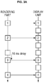
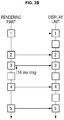
- FIGs. 3A and 3B illustrate a rendering process performed by the rendering module 220.
- image data captured at a frame rate of 24 FPS may not be able to be properly displayed on the display 300, which has a refresh rate of 60 Hz, simply by repeating each of the image frames of the image data only once because one repetition of each of the image frames of the image data cannot meet the refresh rate of the display 300, i.e., 60 refreshes a second.
- a technique called frame rate conversion (FRC) is used in which a half of the image frames of the image data are repeated once and the other half are repeated twice so as to achieve the refresh rate of 60 Hz.
- the interval between the image frames of the image data may differ from the interval between refreshes performed by the display 300.
- a correction process is needed to match the interval between the image frames of the image data to the interval between refreshes performed by the display 300, and this correction process is referred to as rendering.
- the interval between the image frames of the image data may be increased or reduced through rendering to meet the refresh rate of the display 300.
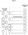
- FIG. 4 illustrates a decoding process performed by the decoder 210.
- the decoder 210 when an operation signal is received from the rendering module 220, the decoder 210 performs decoding.
- the decoder 210 decodes input image data using the processor only when the rendering module 220 is not performing rendering.
- the image data includes image frames, and there are a P frame and an I frame among the image frames.
- the P frame is a frame that is decoded with reference to other frames, but the I frame is a frame that can be decoded independently without reference to other frames. Accordingly, the I frame is generally of higher quality and larger size than the P frame.
- the decoder 210 may not be able to finish the decoding of the I frame, which is large in size, within the period when the processor is not being in use by the rendering module 220. Accordingly, if only part of the I frame is decoded during the period when the processor is not being in use by the rendering module 220, the decoder 210 may decode the rest of the I frame in n stages (where n is an integer greater than 0).
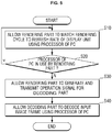
- FIG. 5 is a flowchart illustrating an image processing method of an image processing system, according to an exemplary embodiment.
- the rendering module 220 performs rendering such that a rendering cycle to correspond to the refresh rate of the display 300 (S10). Accordingly, decoded image data transmitted from the decoder 210 to the rendering module 220 can be rendered at a rendering cycle corresponding to the refresh rate of the display 300.
- the rendering module 220 determines whether the processor is being used in rendering (S20). In response to determining that the processor is not being in use by the rendering module 220, an operation signal for the decoder 210 is generated, and the operation signal is transmitted to the decoder 210 (S30).
- the decoder 210 decodes the input image data (S40).
- the operations or steps of the methods or algorithms described above can be embodied as computer readable codes on a computer readable recording medium, or to be transmitted through a transmission medium.
- the computer readable recording medium is any data storage device that can store data which can be thereafter read by a computer system. Examples of the computer readable recording medium include read-only memory (ROM), random-access memory (RAM), compact disc (CD)-ROM, digital versatile disc (DVD), magnetic tape, floppy disk, and optical data storage device, not being limited thereto.
- the transmission medium can include carrier waves transmitted through the Internet or various types of communication channel.
- the computer readable recording medium can also be distributed over network coupled computer systems so that the computer readable code is stored and executed in a distributed fashion.
- At least one of the components, elements, modules or units represented by a block as illustrated in FIG. 2 may be embodied as various numbers of hardware, software and/or firmware structures that execute respective functions described above, according to an exemplary embodiment.
- at least one of these components, elements or units may use a direct circuit structure, such as a memory, processing, logic, a look-up table, etc. that may execute the respective functions through controls of one or more microprocessors or other control apparatuses.
- at least one of these components, elements or units may be specifically embodied by a module, a program, or a part of code, which contains one or more executable instructions for performing specified logic functions, and executed by one or more microprocessors or other control apparatuses.
- At least one of these components, elements or units may further include a processor such as a central processing unit (CPU) that performs the respective functions, a microprocessor, or the like.
- a processor such as a central processing unit (CPU) that performs the respective functions, a microprocessor, or the like.
- CPU central processing unit
- Two or more of these components, elements or units may be combined into one single component, element or unit which performs all operations or functions of the combined two or more components, elements of units.
- at least part of functions of at least one of these components, elements or units may be performed by another of these components, element or units.
- a bus is not illustrated in the above block diagrams, communication between the components, elements or units may be performed through the bus.
- Functional aspects of the above exemplary embodiments may be implemented in algorithms that execute on one or more processors.
- the components, elements or units represented by a block or processing steps may employ any number of related art techniques for electronics configuration, signal processing and/or control, data processing and the like.
Landscapes
- Engineering & Computer Science (AREA)
- Multimedia (AREA)
- Signal Processing (AREA)
- Theoretical Computer Science (AREA)
- Physics & Mathematics (AREA)
- General Physics & Mathematics (AREA)
- Computing Systems (AREA)
- Computer Hardware Design (AREA)
- Compression Or Coding Systems Of Tv Signals (AREA)
Description
- Apparatuses and methods consistent with exemplary embodiments relate to image processing, and more particularly, to image processing to minimize motion judder by preventing a decoder and a rendering part of an image processing system from using a processor of a personal computer (PC) at the same time.
- Closed circuit television (CCTV) images, unlike typical images, which can be viewed one at a time from a single screen, can be viewed by a user while monitoring multiple CCTV cameras at the same time. Network CCTV cameras use a computer video compression technique to reduce the amount of data to be transmitted via a network.
- Image data is generally large in size and is displayed on a monitor after being subjected to compression, transmission, and decompression. These processing or computation operations are generally complicated and cause a load on an entire system. More specifically, the compression of image data is handled separately by a central processing unit (CPU) of each camera, and thus, does not suffer from an overload because the load of the system can be distributed. On the other hand, in the case of decompressing image data for display at a personal computer (PC) system or its equivalents, multiple images are viewed from multiple monitors at the same time, thereby causing an overload.
- When a CPU of the PC system is overloaded, a rendering function for matching a frame rate (in frames per second (FPS)) of input image data to a refresh rate (in Hz) of a display or monitor connected to the PC system may not be properly performed, and as a result, motion judder may occur, i.e., images displayed on a monitor may judder.
-
US5880786 A discloses an apparatus for decoding picture data and a display unit for reading the decoded picture data based on a synchronization signal to obtain a interlace-scan display picture data. -
EP0914008 A2 discloses a data structure of an image signal includes a reproduction cycle identifier indicating whether the cycle of image display for each frame is variable or not. When the display cycle identifier indicates that the display cycle is fixed, display cycle data is inserted in a header of the coded image data, and data relating to the frame number is inserted in each frame. -
US2012262463 A1 discloses virtual vertical synchronization for preventing video tearing artifacts by keeping the video pipeline synchronized with the monitor. Such technique keeps the frame rate of the rendering engine equal to monitor's refresh rate.US2012262463 A1 discloses also dropping undisplayed frames to solve for the frame input lags and remove frame blocking artifact. - Exemplary embodiments of the inventive concept provide an image processing apparatus and a method capable of minimizing motion judder in an image by preventing a decoder and a rendering module from using a same processor at the same time.
- According to an exemplary embodiment, there is provided an image processing apparatus according to
claim 1. - According to an exemplary embodiment, there is provided an image processing method according to claim 8.
- Other features and exemplary embodiments will be apparent from the following detailed description, the drawings, and the claims.
-
-
FIG. 1 is a schematic view of an image processing system, according to an exemplary embodiment. -
FIG. 2 is a block diagram of the image processing system ofFIG. 1 , according to an exemplary embodiment. -
FIGs. 3A and3B illustrate a rendering process performed by a rendering part ofFIG. 2 , according to exemplary embodiments. -
FIG. 4 illustrates a decoding process performed by a decoder ofFIG. 2 , according to an exemplary embodiment. -
FIG. 5 is a flowchart illustrating an image processing method of an image processing system, according to an exemplary embodiment. - The inventive concept will now be described more fully hereinafter with reference to the accompanying drawings, in which exemplary embodiments of the inventive concept are shown. This inventive concept may, however, be embodied in different forms and should not be construed as limited to the embodiments set forth herein. Rather, these embodiments are provided so that this disclosure will be thorough and complete, and will fully convey the scope of the inventive concept to those skilled in the art. The same reference numbers indicate the same components throughout the specification.
- The use of the terms "a" and "an" and "the" and similar referents in the context of describing the inventive concept (especially in the context of the following claims) are to be construed to cover both the singular and the plural, unless otherwise indicated herein or clearly contradicted by context. The terms "comprising," "having," "including," and "containing" are to be construed as open-ended terms (i.e., meaning "including, but not limited to,") unless otherwise noted.
- Spatially relative terms, such as "beneath," "below," "lower," "above," "upper" and the like, may be used herein for ease of description to describe one element or feature's relationship to another element(s) or feature(s) as illustrated in the figures. It will be understood that the spatially relative terms are intended to encompass different orientations of the device in use or operation in addition to the orientation depicted in the figures. For example, if the device in the figures is turned over, elements described as "below" or "beneath" other elements or features would then be oriented "above" the other elements or features. Thus, the exemplary term "below" can encompass both an orientation of above and below. The device may be otherwise oriented (rotated 90 degrees or at other orientations) and the spatially relative descriptors used herein interpreted accordingly.
- Exemplary embodiments will hereinafter be described with reference to the accompanying drawings.
-
FIG. 1 is a schematic view of an image processing system, according to an exemplary embodiment of the invention.FIG. 2 is a block diagram of the image processing system ofFIG. 1 , according to an exemplary embodiment. - Referring to
FIGs. 1 and 2 , the image processing system is a system performing image processing such as decoding, rendering, and the like using the process of a personal computer (PC). The image processing system includes acamera 100, animage processing apparatus 200, and adisplay 300. - The
camera 100 encodes image data, which is obtained by capturing an image of a subject, and outputs the encoded image data to an image processing apparatus via a network. Thecamera 100 includes animage pickup module 110 and anencoder 120. - The
image pickup module 110 generates image data by capturing an image of a subject. Theimage pickup module 110 may include an image sensor such as a charge coupled device (CCD), a complementary metal oxide semiconductor (CMOS) or the like, and an image pickup component such as an optical lens. The image data include image frames such as a predicted (P) frame and an intra (I) frame. - The
encoder 120 encodes the image data generated by theimage pickup module 110. For example, theencoder 120 reduces the size of the image data to encode the image data. It is obvious to a person skilled in the art to which the inventive concept pertains that theencoder 120 may encode the image data generated by theimage pickup module 110 into various formats such as Moving Picture Experts Group (MPEG)-1 or MPEG-4, not being limited thereto. - Although not specifically illustrated in
FIGs. 1 and 2 , the image processing system may also include a preprocessing module (not illustrated), which converts analog image data generated by theimage pickup module 110 into digital data. The digital image data obtained by the preprocessing part may be input to theencoder 120. - The
image processing apparatus 200 may be implemented as a PC equipped with at least one processor (not illustrated). In response to a frame rate (in frames per second (FPS)) of the image data generated by thecamera 100 not precisely corresponding with a refresh rate of thedisplay 300, theimage processing apparatus 200 may perform correction such that the frame rate of the image data can precisely match the refresh rate of thedisplay unit 300. Theimage processing apparatus 200 will be described later in detail. - The
image processing apparatus 200 may include adecoder 210, arendering module 220, and a processor (not illustrated). - The
decoder 210 decodes the encoded image data provided by theencoder 120 using the processor. Thedecoder 210 will be described later in detail. - The
rendering module 220 renders the decoded image data provided by thedecoder 210 at a rendering cycle corresponding to the refresh rate of thedisplay 300 by using the processor. - The refresh rate of the
display 300 may be the number of times in a second that an image frame is output by thedisplay 300, or the number of times per second thedisplay 300 refreshes its screen. The refresh rate may also be defined by the number of times in a second that thedisplay 300 updates its buffer (not shown). For example, when thedisplay 300 has a refresh rate of 60 Hz, thedisplay 300 outputs an image frame 60 times in one second. - A rendering cycle includes a rendering period during which the decoded image data is rendered and a non-rendering period during which the decoded image data is not rendered, and the rendering period and the non-rendering period may appear repeatedly.
- The
rendering module 220 renders the decoded image data using the processor so that the decoded image data corresponds to the refresh rate of thedisplay 300. Therendering module 220 will be described later in detail. - During a period when the decoded image data is not being rendered, the
rendering module 220 does not use the processor. This period may be the non-rendering period in the rendering cycle. Accordingly, therendering module 220 renders the decoded image data using the processor according to the aforementioned rendering cycle. - While not using the processor for rendering or when rendering is stopped, the
rendering module 220 generates an operation signal for thedecoder 210 and transmits the operation signal to thedecoder 210. That is, therendering module 220 generates the operation signal for thedecoder 210 and transmits the operation signal to thedecoder 210, while not performing the image rendering. Here, the operation signal may be generated and transmitted immediately after non-use of the processor for the rendering begins or the rendering by the processor is stopped. - When the operation signal being received from the
rendering module 220, thedecoder 210 may determine that the processor is not being in use by therendering module 220. Accordingly, thedecoder 210 may decode the image data using the processor upon receipt of the operation signal from therendering module 220. - The
decoder 210 may decode the image data that is input within a predetermined period after the receipt of the operation signal. It is obvious to a person skilled in the art to which the inventive concept pertains that the predetermined period after the receipt of the operation signal may be included in a period when the processor is not being in use by therendering module 220. - According to an exemplary embodiment, instead of generating the operation signal by the
rendering module 220 to trigger the decoding of the image data, thedecoder 210 may decode the image data by recognizing the non-rendering period in the rendering cycle which is predetermined. - According to an exemplary embodiment, the
rendering module 220 may generate a decoding halt signal and may transmit the decoding halt signal to thedecoder 210. When the decoding halt signal is received from therendering module 220, thedecoder 210 may determine that the processor is being in use by therendering module 220. Accordingly, thedecoder 210 may stop using the processor to decode the image data. That is, thedecoder 210 may decode the image data that is input during a period between the receipt of the operation signal and the receipt of the decoding halt signal. - The
rendering module 220 checks the refresh rate of thedisplay unit 300 at predetermined time intervals. For example, therendering module 220 may check the refresh rate of thedisplay 300 by checking scan lines of thedisplay 300 at intervals of 100 ms. - According to an exemplary embodiment, the
rendering module 220 may check the scan lines of thedisplay 300 using a Vertical Sync Interrupt Service to check the refresh rate of thedisplay 300. - If the refresh rate of the
display 300 is changed due to a change of a resolution of thedisplay 300 by a user's manipulation, therendering module 220 may identify the changed refresh rate of thedisplay 300 and may change the rendering cycle to correspond to the changed refresh rate of thedisplay 300. - For example, in response to the user changing the resolution of the
display 300 so that the refresh rate of thedisplay 300 is changed from 60 Hz to 75 Hz, therendering module 220 may change the rendering cycle to 75 FPS to correspond to the changed refresh rate of thedisplay 300. - The processor may process a large amount of computation so that multiple functions such as decoding, rendering, scaling and the like are executed. The processor may be implemented as a central processing unit (CPU) that is programmed to serve as both a processing unit and a control unit.
- The
rendering module 220 and thedecoder 210 share the processor together, but thedecoder 210 performs decoding using the processor only when the processor is not being in use by therendering module 220. Accordingly, since therendering module 220 and thedecoder 210 do not use the processor at the same time, therendering module 220 and thedecoder 210 do not produce an excessive load on the processor, compared to a case when they use the processor at the same time. Since there is no excessive load on the processor, motion judder can be minimized when the image data is displayed on thedisplay 300. - Although not specifically illustrated in
FIGs. 1 and 2 , the image processing system may also include a buffer (not illustrated), which temporarily stores image data decoded by thedecoder 210. - The
display 300 outputs the rendered image data. Thedisplay 300 is set to a predetermined refresh rate, and the refresh rate of thedisplay 300 may be changed by the user's manipulation. -
FIGs. 3A and3B illustrate a rendering process performed by therendering module 220. - Referring to
FIGs. 2 ,3A and3B , image data captured at a frame rate of 24 FPS may not be able to be properly displayed on thedisplay 300, which has a refresh rate of 60 Hz, simply by repeating each of the image frames of the image data only once because one repetition of each of the image frames of the image data cannot meet the refresh rate of thedisplay 300, i.e., 60 refreshes a second. Accordingly, a technique called frame rate conversion (FRC) is used in which a half of the image frames of the image data are repeated once and the other half are repeated twice so as to achieve the refresh rate of 60 Hz. - However, as illustrated in
FIGs. 3A and3B , the interval between the image frames of the image data may differ from the interval between refreshes performed by thedisplay 300. Thus, a correction process is needed to match the interval between the image frames of the image data to the interval between refreshes performed by thedisplay 300, and this correction process is referred to as rendering. The interval between the image frames of the image data may be increased or reduced through rendering to meet the refresh rate of thedisplay 300. -
FIG. 4 illustrates a decoding process performed by thedecoder 210. - Referring to
FIGs. 2 and4 , when an operation signal is received from therendering module 220, thedecoder 210 performs decoding. Thedecoder 210 decodes input image data using the processor only when therendering module 220 is not performing rendering. - The image data includes image frames, and there are a P frame and an I frame among the image frames.
- The P frame is a frame that is decoded with reference to other frames, but the I frame is a frame that can be decoded independently without reference to other frames. Accordingly, the I frame is generally of higher quality and larger size than the P frame.
- The
decoder 210 may not be able to finish the decoding of the I frame, which is large in size, within the period when the processor is not being in use by therendering module 220. Accordingly, if only part of the I frame is decoded during the period when the processor is not being in use by therendering module 220, thedecoder 210 may decode the rest of the I frame in n stages (where n is an integer greater than 0). -
FIG. 5 is a flowchart illustrating an image processing method of an image processing system, according to an exemplary embodiment. - Referring to
FIGs. 2 and5 , therendering module 220 performs rendering such that a rendering cycle to correspond to the refresh rate of the display 300 (S10). Accordingly, decoded image data transmitted from thedecoder 210 to therendering module 220 can be rendered at a rendering cycle corresponding to the refresh rate of thedisplay 300. - The
rendering module 220 determines whether the processor is being used in rendering (S20). In response to determining that the processor is not being in use by therendering module 220, an operation signal for thedecoder 210 is generated, and the operation signal is transmitted to the decoder 210 (S30). - In response to the operation signal being received, the
decoder 210 decodes the input image data (S40). - The operations or steps of the methods or algorithms described above can be embodied as computer readable codes on a computer readable recording medium, or to be transmitted through a transmission medium. The computer readable recording medium is any data storage device that can store data which can be thereafter read by a computer system. Examples of the computer readable recording medium include read-only memory (ROM), random-access memory (RAM), compact disc (CD)-ROM, digital versatile disc (DVD), magnetic tape, floppy disk, and optical data storage device, not being limited thereto. The transmission medium can include carrier waves transmitted through the Internet or various types of communication channel. The computer readable recording medium can also be distributed over network coupled computer systems so that the computer readable code is stored and executed in a distributed fashion.
- At least one of the components, elements, modules or units represented by a block as illustrated in
FIG. 2 may be embodied as various numbers of hardware, software and/or firmware structures that execute respective functions described above, according to an exemplary embodiment. For example, at least one of these components, elements or units may use a direct circuit structure, such as a memory, processing, logic, a look-up table, etc. that may execute the respective functions through controls of one or more microprocessors or other control apparatuses. Also, at least one of these components, elements or units may be specifically embodied by a module, a program, or a part of code, which contains one or more executable instructions for performing specified logic functions, and executed by one or more microprocessors or other control apparatuses. Also, at least one of these components, elements or units may further include a processor such as a central processing unit (CPU) that performs the respective functions, a microprocessor, or the like. Two or more of these components, elements or units may be combined into one single component, element or unit which performs all operations or functions of the combined two or more components, elements of units. Also, at least part of functions of at least one of these components, elements or units may be performed by another of these components, element or units. Further, although a bus is not illustrated in the above block diagrams, communication between the components, elements or units may be performed through the bus. Functional aspects of the above exemplary embodiments may be implemented in algorithms that execute on one or more processors. Furthermore, the components, elements or units represented by a block or processing steps may employ any number of related art techniques for electronics configuration, signal processing and/or control, data processing and the like. - It should be understood that the exemplary embodiments described herein should be considered in a descriptive sense only and not for purposes of limitation. Descriptions of features or aspects within each exemplary embodiment should typically be considered as available for other similar features or aspects in other exemplary embodiments. While the above exemplary embodiments have been described with reference to the accompanying drawings, it will be understood by those of ordinary skill in the art that various changes in form and details may be made therein without departing from the scope of the inventive concept as defined by the following claims
Claims (13)
- An image processing apparatus comprising a processor, the processor being configured to implement:a decoder (210) which decodes input image data; anda rendering module (220) which renders the decoded image data according to a rendering cycle which corresponds to a refresh rate of a display (300) to display a plurality of image frames of the decoded image data,wherein the rendering cycle comprises a rendering period during which the decoded image data is rendered and a non-rendering period during which the decoded image data is not rendered,wherein the decoder (210) is configured to decode the input image data during the non-rendering period among the rendering period and the non-rendering period such that the rendering module (220) and the decoder (219) do not use the processor at the same time,wherein the display (300) is configured to output the decoded and rendered image data, andwherein the rendering module (220) is configured to match an interval between the image frames of the image data to an interval between refreshes of the display (300) to render the decoded image data.
- The image processing apparatus of claim 1, wherein the rendering module (220) is configured to generate an operation signal for the decoder (210) and to transmit the operation signal to the decoder (210), and in response to the operation signal being received, the decoder (210) is configured to decode the input image data.
- The image processing apparatus of claim 1, wherein in response to only part of one image frame, constituting the input image data, being decoded during a current time period when the processor is not being in use for rendering by the rendering module (220), the decoder (210) is configured to decode the rest of the image frame in a plurality of next time periods.
- The image processing apparatus of claim 1, wherein in response to only part of one image frame constituting the input image data being decoded during a current time period when the processor is not being in use for rendering by the rendering module (220), the decoder (210) is configured to decode another part of the image frame in a next time period when the processor is not being in use for rendering by the rendering module (220).
- The image processing apparatus of claim 4, wherein the image processing apparatus is configured that the next time period arrives after the current time period and a time period when the processor is used by the rendering module (220).
- The image processing apparatus of claim 1, wherein the rendering module (220) is configured to transmit a decoding halt signal to the decoder (210) to halt the decoding of the input image data and to render the decoded image data.
- The image processing apparatus of claim 1, wherein the rendering module (220) is configured to check the refresh rate of the display at predetermined time intervals and to match the rendering cycle to the refresh rate of the display.
- An image processing method using a processor, the method implemented by the processor comprising:decoding input image data;rendering the decoded image data according to a rendering cycle which corresponds to a refresh rate of a display to display a plurality of image frames of the decoded image data,wherein the rendering cycle comprises a rendering period during which the decoded image data is rendered and a non-rendering period during which the decoded image data is not rendered,wherein the decoding decodes the input image data during the non-rendering period among the rendering period and the non-rendering period such that the processor does not perform rendering and decoding at the same time,wherein the display (300) outputs the decoded and rendered image data, andwherein the rendering matches an interval between the image frames of the image data to an interval between refreshes of the display (300) to render the decoded image data.
- The method of claim 8, further comprising generating and transmitting an operation signal to trigger the decoding the input image data.
- The method of claim 8, wherein the decoding the input image data comprises, in response to only part of one image frame, constituting the input image data, being decoded during a current time period when the processor is not being in use for rendering, decoding the rest of the image frame in a plurality of next time periods.
- The method of claim 8, wherein the decoding the input image data comprises, in response to only part of one image frame, constituting the input image data, being decoded during a current time period when the processor is not being in use for rendering, decoding another part of the image frame in a next time period when the processor is not being in use for rendering.
- The method of claim 11, wherein the next time period arrives after the current time period and a time period when the processor is used for rendering.
- The method of claim 8, further comprising generating and transmitting a decoding halt signal to halt the decoding the input image data and rendering the decoded image data.
Applications Claiming Priority (1)
| Application Number | Priority Date | Filing Date | Title |
|---|---|---|---|
| KR1020150036563A KR102312681B1 (en) | 2015-03-17 | 2015-03-17 | System and Method of processing image |
Publications (2)
| Publication Number | Publication Date |
|---|---|
| EP3070598A1 EP3070598A1 (en) | 2016-09-21 |
| EP3070598B1 true EP3070598B1 (en) | 2020-12-30 |
Family
ID=55696896
Family Applications (1)
| Application Number | Title | Priority Date | Filing Date |
|---|---|---|---|
| EP16160051.5A Active EP3070598B1 (en) | 2015-03-17 | 2016-03-14 | Image processing system and method |
Country Status (3)
| Country | Link |
|---|---|
| US (1) | US9883195B2 (en) |
| EP (1) | EP3070598B1 (en) |
| KR (1) | KR102312681B1 (en) |
Families Citing this family (2)
| Publication number | Priority date | Publication date | Assignee | Title |
|---|---|---|---|---|
| US8879858B1 (en) * | 2013-10-01 | 2014-11-04 | Gopro, Inc. | Multi-channel bit packing engine |
| CN111836104B (en) * | 2020-07-09 | 2022-01-28 | 海信视像科技股份有限公司 | Display apparatus and display method |
Family Cites Families (20)
| Publication number | Priority date | Publication date | Assignee | Title |
|---|---|---|---|---|
| US5821989A (en) | 1990-06-11 | 1998-10-13 | Vrex, Inc. | Stereoscopic 3-D viewing system and glasses having electrooptical shutters controlled by control signals produced using horizontal pulse detection within the vertical synchronization pulse period of computer generated video signals |
| DE69422943T2 (en) * | 1993-06-22 | 2000-06-29 | Canon K.K., Tokio/Tokyo | Image processing device |
| US5880786A (en) * | 1994-06-15 | 1999-03-09 | Hitachi, Ltd. | Apparatus for picture decoding having frame memories commonly connected to one data bus and one address bus |
| KR100215824B1 (en) | 1996-04-09 | 1999-08-16 | 구자홍 | MPEG decoder frame memory and video data decoding method |
| JP3232052B2 (en) * | 1997-10-31 | 2001-11-26 | 松下電器産業株式会社 | Image decoding method |
| US6384846B1 (en) | 1998-12-11 | 2002-05-07 | Hitachi America Ltd. | Methods and apparatus for rendering multiple images using a limited rendering resource |
| US6469744B1 (en) * | 1999-07-06 | 2002-10-22 | Hitachi America, Ltd. | Methods and apparatus for encoding, decoding and displaying images in a manner that produces smooth motion |
| KR100457899B1 (en) * | 2000-08-25 | 2004-11-18 | 마츠시타 덴끼 산교 가부시키가이샤 | Decoding device, electronic device, and decoding method |
| JP3551139B2 (en) * | 2000-09-21 | 2004-08-04 | 日本電気株式会社 | Moving image reproducing system and moving image reproducing method |
| US7256797B2 (en) * | 2003-01-31 | 2007-08-14 | Yamaha Corporation | Image processing device with synchronized sprite rendering and sprite buffer |
| US8560753B1 (en) * | 2005-03-30 | 2013-10-15 | Teradici Corporation | Method and apparatus for remote input/output in a computer system |
| US8345768B1 (en) * | 2005-07-28 | 2013-01-01 | Teradici Corporation | Progressive block encoding using region analysis |
| US9426522B2 (en) | 2007-07-10 | 2016-08-23 | Qualcomm Incorporated | Early rendering for fast channel switching |
| KR101425620B1 (en) * | 2007-12-17 | 2014-07-31 | 삼성전자주식회사 | Method and apparatus for video decoding based on a multi-core processor |
| US8754904B2 (en) | 2011-04-03 | 2014-06-17 | Lucidlogix Software Solutions, Ltd. | Virtualization method of vertical-synchronization in graphics systems |
| CN102063695A (en) * | 2009-11-12 | 2011-05-18 | 马维尔国际贸易有限公司 | Power saving in mobile devices by optimizing frame rate output |
| EP2498494A1 (en) | 2011-03-11 | 2012-09-12 | Thomson Licensing | Decoder and method at the decoder for synchronizing the rendering of contents received through different networks |
| EP2866438A4 (en) * | 2012-06-25 | 2015-12-02 | Nec Corp | VIDEO ENCODING / DECODING DEVICE, METHOD, AND PROGRAM |
| US9641867B2 (en) * | 2014-10-24 | 2017-05-02 | Megachips Corporation | Image processor |
| JP2017005611A (en) * | 2015-06-15 | 2017-01-05 | 富士通株式会社 | Dynamic image decoding device and dynamic image decoding method |
-
2015
- 2015-03-17 KR KR1020150036563A patent/KR102312681B1/en active Active
-
2016
- 2016-01-11 US US14/992,198 patent/US9883195B2/en active Active
- 2016-03-14 EP EP16160051.5A patent/EP3070598B1/en active Active
Non-Patent Citations (1)
| Title |
|---|
| None * |
Also Published As
| Publication number | Publication date |
|---|---|
| KR20160111662A (en) | 2016-09-27 |
| KR102312681B1 (en) | 2021-10-13 |
| EP3070598A1 (en) | 2016-09-21 |
| US9883195B2 (en) | 2018-01-30 |
| US20160277753A1 (en) | 2016-09-22 |
Similar Documents
| Publication | Publication Date | Title |
|---|---|---|
| US10070098B2 (en) | Method and system of adjusting video quality based on viewer distance to a display | |
| JP4421897B2 (en) | Simultaneous dual pipeline for acquisition, processing and transmission of digital video and high-resolution digital still photos | |
| CN104702851B (en) | Use the powerful auto-exposure control of embedded data | |
| EP2629520B1 (en) | Apparatus and method for shooting moving picture in camera device | |
| US20030169818A1 (en) | Video transcoder based joint video and still image pipeline with still burst mode | |
| WO2014001381A2 (en) | System and method for encoding video content using virtual intra-frames | |
| US9996894B2 (en) | Image processing device, video subsystem and video pipeline | |
| KR102268597B1 (en) | Appratus and method for processing image | |
| US20110302334A1 (en) | Flow Control in Real-Time Transmission of Non-Uniform Data Rate Encoded Video Over a Universal Serial Bus | |
| US8264587B2 (en) | Increasing frame rate for imaging | |
| US20090051766A1 (en) | Monitoring System and Imaging Device | |
| US20130007206A1 (en) | Transmission apparatus, control method for transmission apparatus, and storage medium | |
| US9883195B2 (en) | Image processing system and method for decoding during non-rendering period | |
| US9674554B2 (en) | Image processing system with coding mode and method of operation thereof | |
| KR101280443B1 (en) | apparatus of processing regional image and method thereof | |
| US12342022B2 (en) | Video failover recording | |
| US20070053432A1 (en) | Image processing apparatus | |
| JP2007134788A (en) | Image processing apparatus and program | |
| KR101336820B1 (en) | Apparatus and method for decoding specialized multi-channel trick mode | |
| US9294782B1 (en) | Image processing system with artifact reduction mechanism and method of operation thereof | |
| US20240129496A1 (en) | Method and system of video coding with handling of illegal block partitions | |
| US20180070098A1 (en) | Encoding apparatus, decoding apparatus, and image processing system | |
| US20200195874A1 (en) | Real Time Video | |
| KR20080113649A (en) | An image processing apparatus and method for displaying a captured image without time delay, and a computer-readable recording medium that includes the program and the method. | |
| JP2002044621A (en) | Image transmission device |
Legal Events
| Date | Code | Title | Description |
|---|---|---|---|
| PUAI | Public reference made under article 153(3) epc to a published international application that has entered the european phase |
Free format text: ORIGINAL CODE: 0009012 |
|
| 17P | Request for examination filed |
Effective date: 20160314 |
|
| AK | Designated contracting states |
Kind code of ref document: A1 Designated state(s): AL AT BE BG CH CY CZ DE DK EE ES FI FR GB GR HR HU IE IS IT LI LT LU LV MC MK MT NL NO PL PT RO RS SE SI SK SM TR |
|
| AX | Request for extension of the european patent |
Extension state: BA ME |
|
| STAA | Information on the status of an ep patent application or granted ep patent |
Free format text: STATUS: EXAMINATION IS IN PROGRESS |
|
| 17Q | First examination report despatched |
Effective date: 20181126 |
|
| RAP1 | Party data changed (applicant data changed or rights of an application transferred) |
Owner name: HANWHA TECHWIN CO., LTD. |
|
| GRAP | Despatch of communication of intention to grant a patent |
Free format text: ORIGINAL CODE: EPIDOSNIGR1 |
|
| STAA | Information on the status of an ep patent application or granted ep patent |
Free format text: STATUS: GRANT OF PATENT IS INTENDED |
|
| RIC1 | Information provided on ipc code assigned before grant |
Ipc: H04N 7/18 20060101ALI20200706BHEP Ipc: H04N 21/43 20110101ALI20200706BHEP Ipc: H04N 21/4402 20110101ALI20200706BHEP Ipc: G06F 3/14 20060101AFI20200706BHEP Ipc: G09G 5/00 20060101ALI20200706BHEP |
|
| INTG | Intention to grant announced |
Effective date: 20200724 |
|
| GRAS | Grant fee paid |
Free format text: ORIGINAL CODE: EPIDOSNIGR3 |
|
| GRAA | (expected) grant |
Free format text: ORIGINAL CODE: 0009210 |
|
| STAA | Information on the status of an ep patent application or granted ep patent |
Free format text: STATUS: THE PATENT HAS BEEN GRANTED |
|
| AK | Designated contracting states |
Kind code of ref document: B1 Designated state(s): AL AT BE BG CH CY CZ DE DK EE ES FI FR GB GR HR HU IE IS IT LI LT LU LV MC MK MT NL NO PL PT RO RS SE SI SK SM TR |
|
| REG | Reference to a national code |
Ref country code: GB Ref legal event code: FG4D |
|
| REG | Reference to a national code |
Ref country code: AT Ref legal event code: REF Ref document number: 1350603 Country of ref document: AT Kind code of ref document: T Effective date: 20210115 |
|
| REG | Reference to a national code |
Ref country code: DE Ref legal event code: R096 Ref document number: 602016050480 Country of ref document: DE |
|
| REG | Reference to a national code |
Ref country code: IE Ref legal event code: FG4D |
|
| PG25 | Lapsed in a contracting state [announced via postgrant information from national office to epo] |
Ref country code: NO Free format text: LAPSE BECAUSE OF FAILURE TO SUBMIT A TRANSLATION OF THE DESCRIPTION OR TO PAY THE FEE WITHIN THE PRESCRIBED TIME-LIMIT Effective date: 20210330 Ref country code: FI Free format text: LAPSE BECAUSE OF FAILURE TO SUBMIT A TRANSLATION OF THE DESCRIPTION OR TO PAY THE FEE WITHIN THE PRESCRIBED TIME-LIMIT Effective date: 20201230 Ref country code: RS Free format text: LAPSE BECAUSE OF FAILURE TO SUBMIT A TRANSLATION OF THE DESCRIPTION OR TO PAY THE FEE WITHIN THE PRESCRIBED TIME-LIMIT Effective date: 20201230 Ref country code: GR Free format text: LAPSE BECAUSE OF FAILURE TO SUBMIT A TRANSLATION OF THE DESCRIPTION OR TO PAY THE FEE WITHIN THE PRESCRIBED TIME-LIMIT Effective date: 20210331 |
|
| REG | Reference to a national code |
Ref country code: AT Ref legal event code: MK05 Ref document number: 1350603 Country of ref document: AT Kind code of ref document: T Effective date: 20201230 |
|
| PG25 | Lapsed in a contracting state [announced via postgrant information from national office to epo] |
Ref country code: BG Free format text: LAPSE BECAUSE OF FAILURE TO SUBMIT A TRANSLATION OF THE DESCRIPTION OR TO PAY THE FEE WITHIN THE PRESCRIBED TIME-LIMIT Effective date: 20210330 Ref country code: SE Free format text: LAPSE BECAUSE OF FAILURE TO SUBMIT A TRANSLATION OF THE DESCRIPTION OR TO PAY THE FEE WITHIN THE PRESCRIBED TIME-LIMIT Effective date: 20201230 Ref country code: LV Free format text: LAPSE BECAUSE OF FAILURE TO SUBMIT A TRANSLATION OF THE DESCRIPTION OR TO PAY THE FEE WITHIN THE PRESCRIBED TIME-LIMIT Effective date: 20201230 |
|
| REG | Reference to a national code |
Ref country code: NL Ref legal event code: MP Effective date: 20201230 |
|
| PG25 | Lapsed in a contracting state [announced via postgrant information from national office to epo] |
Ref country code: HR Free format text: LAPSE BECAUSE OF FAILURE TO SUBMIT A TRANSLATION OF THE DESCRIPTION OR TO PAY THE FEE WITHIN THE PRESCRIBED TIME-LIMIT Effective date: 20201230 |
|
| REG | Reference to a national code |
Ref country code: LT Ref legal event code: MG9D |
|
| PG25 | Lapsed in a contracting state [announced via postgrant information from national office to epo] |
Ref country code: RO Free format text: LAPSE BECAUSE OF FAILURE TO SUBMIT A TRANSLATION OF THE DESCRIPTION OR TO PAY THE FEE WITHIN THE PRESCRIBED TIME-LIMIT Effective date: 20201230 Ref country code: SK Free format text: LAPSE BECAUSE OF FAILURE TO SUBMIT A TRANSLATION OF THE DESCRIPTION OR TO PAY THE FEE WITHIN THE PRESCRIBED TIME-LIMIT Effective date: 20201230 Ref country code: PT Free format text: LAPSE BECAUSE OF FAILURE TO SUBMIT A TRANSLATION OF THE DESCRIPTION OR TO PAY THE FEE WITHIN THE PRESCRIBED TIME-LIMIT Effective date: 20210430 Ref country code: EE Free format text: LAPSE BECAUSE OF FAILURE TO SUBMIT A TRANSLATION OF THE DESCRIPTION OR TO PAY THE FEE WITHIN THE PRESCRIBED TIME-LIMIT Effective date: 20201230 Ref country code: CZ Free format text: LAPSE BECAUSE OF FAILURE TO SUBMIT A TRANSLATION OF THE DESCRIPTION OR TO PAY THE FEE WITHIN THE PRESCRIBED TIME-LIMIT Effective date: 20201230 Ref country code: NL Free format text: LAPSE BECAUSE OF FAILURE TO SUBMIT A TRANSLATION OF THE DESCRIPTION OR TO PAY THE FEE WITHIN THE PRESCRIBED TIME-LIMIT Effective date: 20201230 Ref country code: LT Free format text: LAPSE BECAUSE OF FAILURE TO SUBMIT A TRANSLATION OF THE DESCRIPTION OR TO PAY THE FEE WITHIN THE PRESCRIBED TIME-LIMIT Effective date: 20201230 |
|
| PG25 | Lapsed in a contracting state [announced via postgrant information from national office to epo] |
Ref country code: PL Free format text: LAPSE BECAUSE OF FAILURE TO SUBMIT A TRANSLATION OF THE DESCRIPTION OR TO PAY THE FEE WITHIN THE PRESCRIBED TIME-LIMIT Effective date: 20201230 Ref country code: AT Free format text: LAPSE BECAUSE OF FAILURE TO SUBMIT A TRANSLATION OF THE DESCRIPTION OR TO PAY THE FEE WITHIN THE PRESCRIBED TIME-LIMIT Effective date: 20201230 |
|
| PG25 | Lapsed in a contracting state [announced via postgrant information from national office to epo] |
Ref country code: IS Free format text: LAPSE BECAUSE OF FAILURE TO SUBMIT A TRANSLATION OF THE DESCRIPTION OR TO PAY THE FEE WITHIN THE PRESCRIBED TIME-LIMIT Effective date: 20210430 |
|
| REG | Reference to a national code |
Ref country code: DE Ref legal event code: R097 Ref document number: 602016050480 Country of ref document: DE |
|
| PG25 | Lapsed in a contracting state [announced via postgrant information from national office to epo] |
Ref country code: IT Free format text: LAPSE BECAUSE OF FAILURE TO SUBMIT A TRANSLATION OF THE DESCRIPTION OR TO PAY THE FEE WITHIN THE PRESCRIBED TIME-LIMIT Effective date: 20201230 Ref country code: AL Free format text: LAPSE BECAUSE OF FAILURE TO SUBMIT A TRANSLATION OF THE DESCRIPTION OR TO PAY THE FEE WITHIN THE PRESCRIBED TIME-LIMIT Effective date: 20201230 Ref country code: MC Free format text: LAPSE BECAUSE OF FAILURE TO SUBMIT A TRANSLATION OF THE DESCRIPTION OR TO PAY THE FEE WITHIN THE PRESCRIBED TIME-LIMIT Effective date: 20201230 |
|
| REG | Reference to a national code |
Ref country code: CH Ref legal event code: PL |
|
| PLBE | No opposition filed within time limit |
Free format text: ORIGINAL CODE: 0009261 |
|
| STAA | Information on the status of an ep patent application or granted ep patent |
Free format text: STATUS: NO OPPOSITION FILED WITHIN TIME LIMIT |
|
| GBPC | Gb: european patent ceased through non-payment of renewal fee |
Effective date: 20210330 |
|
| PG25 | Lapsed in a contracting state [announced via postgrant information from national office to epo] |
Ref country code: ES Free format text: LAPSE BECAUSE OF FAILURE TO SUBMIT A TRANSLATION OF THE DESCRIPTION OR TO PAY THE FEE WITHIN THE PRESCRIBED TIME-LIMIT Effective date: 20201230 Ref country code: DK Free format text: LAPSE BECAUSE OF FAILURE TO SUBMIT A TRANSLATION OF THE DESCRIPTION OR TO PAY THE FEE WITHIN THE PRESCRIBED TIME-LIMIT Effective date: 20201230 |
|
| 26N | No opposition filed |
Effective date: 20211001 |
|
| REG | Reference to a national code |
Ref country code: BE Ref legal event code: MM Effective date: 20210331 |
|
| PG25 | Lapsed in a contracting state [announced via postgrant information from national office to epo] |
Ref country code: LU Free format text: LAPSE BECAUSE OF NON-PAYMENT OF DUE FEES Effective date: 20210314 Ref country code: LI Free format text: LAPSE BECAUSE OF NON-PAYMENT OF DUE FEES Effective date: 20210331 Ref country code: CH Free format text: LAPSE BECAUSE OF NON-PAYMENT OF DUE FEES Effective date: 20210331 Ref country code: FR Free format text: LAPSE BECAUSE OF NON-PAYMENT OF DUE FEES Effective date: 20210331 Ref country code: IE Free format text: LAPSE BECAUSE OF NON-PAYMENT OF DUE FEES Effective date: 20210314 Ref country code: GB Free format text: LAPSE BECAUSE OF NON-PAYMENT OF DUE FEES Effective date: 20210330 |
|
| PG25 | Lapsed in a contracting state [announced via postgrant information from national office to epo] |
Ref country code: SI Free format text: LAPSE BECAUSE OF FAILURE TO SUBMIT A TRANSLATION OF THE DESCRIPTION OR TO PAY THE FEE WITHIN THE PRESCRIBED TIME-LIMIT Effective date: 20201230 |
|
| PG25 | Lapsed in a contracting state [announced via postgrant information from national office to epo] |
Ref country code: IS Free format text: LAPSE BECAUSE OF FAILURE TO SUBMIT A TRANSLATION OF THE DESCRIPTION OR TO PAY THE FEE WITHIN THE PRESCRIBED TIME-LIMIT Effective date: 20210430 |
|
| PG25 | Lapsed in a contracting state [announced via postgrant information from national office to epo] |
Ref country code: BE Free format text: LAPSE BECAUSE OF NON-PAYMENT OF DUE FEES Effective date: 20210331 |
|
| PG25 | Lapsed in a contracting state [announced via postgrant information from national office to epo] |
Ref country code: HU Free format text: LAPSE BECAUSE OF FAILURE TO SUBMIT A TRANSLATION OF THE DESCRIPTION OR TO PAY THE FEE WITHIN THE PRESCRIBED TIME-LIMIT; INVALID AB INITIO Effective date: 20160314 |
|
| PG25 | Lapsed in a contracting state [announced via postgrant information from national office to epo] |
Ref country code: CY Free format text: LAPSE BECAUSE OF FAILURE TO SUBMIT A TRANSLATION OF THE DESCRIPTION OR TO PAY THE FEE WITHIN THE PRESCRIBED TIME-LIMIT Effective date: 20201230 |
|
| PG25 | Lapsed in a contracting state [announced via postgrant information from national office to epo] |
Ref country code: SM Free format text: LAPSE BECAUSE OF FAILURE TO SUBMIT A TRANSLATION OF THE DESCRIPTION OR TO PAY THE FEE WITHIN THE PRESCRIBED TIME-LIMIT Effective date: 20201230 |
|
| REG | Reference to a national code |
Ref country code: DE Ref legal event code: R081 Ref document number: 602016050480 Country of ref document: DE Owner name: HANWHA VISION CO., LTD., SEONGNAM-SI, KR Free format text: FORMER OWNER: HANWHA TECHWIN CO., LTD., SEONGNAM-SI, GYEONGGI-DO, KR |
|
| PG25 | Lapsed in a contracting state [announced via postgrant information from national office to epo] |
Ref country code: MK Free format text: LAPSE BECAUSE OF FAILURE TO SUBMIT A TRANSLATION OF THE DESCRIPTION OR TO PAY THE FEE WITHIN THE PRESCRIBED TIME-LIMIT Effective date: 20201230 |
|
| PG25 | Lapsed in a contracting state [announced via postgrant information from national office to epo] |
Ref country code: TR Free format text: LAPSE BECAUSE OF FAILURE TO SUBMIT A TRANSLATION OF THE DESCRIPTION OR TO PAY THE FEE WITHIN THE PRESCRIBED TIME-LIMIT Effective date: 20201230 |
|
| PG25 | Lapsed in a contracting state [announced via postgrant information from national office to epo] |
Ref country code: MT Free format text: LAPSE BECAUSE OF FAILURE TO SUBMIT A TRANSLATION OF THE DESCRIPTION OR TO PAY THE FEE WITHIN THE PRESCRIBED TIME-LIMIT Effective date: 20201230 |
|
| PGFP | Annual fee paid to national office [announced via postgrant information from national office to epo] |
Ref country code: DE Payment date: 20260220 Year of fee payment: 11 |