EP3070452A1 - Correction device, correction method, program, and electrostatic capacitance type pressure sensor - Google Patents
Correction device, correction method, program, and electrostatic capacitance type pressure sensor Download PDFInfo
- Publication number
- EP3070452A1 EP3070452A1 EP16160457.4A EP16160457A EP3070452A1 EP 3070452 A1 EP3070452 A1 EP 3070452A1 EP 16160457 A EP16160457 A EP 16160457A EP 3070452 A1 EP3070452 A1 EP 3070452A1
- Authority
- EP
- European Patent Office
- Prior art keywords
- load
- electrostatic capacitance
- time
- hysteresis
- correction
- Prior art date
- Legal status (The legal status is an assumption and is not a legal conclusion. Google has not performed a legal analysis and makes no representation as to the accuracy of the status listed.)
- Granted
Links
Images



Classifications
-
- G—PHYSICS
- G01—MEASURING; TESTING
- G01L—MEASURING FORCE, STRESS, TORQUE, WORK, MECHANICAL POWER, MECHANICAL EFFICIENCY, OR FLUID PRESSURE
- G01L25/00—Testing or calibrating of apparatus for measuring force, torque, work, mechanical power, or mechanical efficiency
-
- G—PHYSICS
- G01—MEASURING; TESTING
- G01L—MEASURING FORCE, STRESS, TORQUE, WORK, MECHANICAL POWER, MECHANICAL EFFICIENCY, OR FLUID PRESSURE
- G01L27/00—Testing or calibrating of apparatus for measuring fluid pressure
- G01L27/002—Calibrating, i.e. establishing true relation between transducer output value and value to be measured, zeroing, linearising or span error determination
-
- G—PHYSICS
- G01—MEASURING; TESTING
- G01L—MEASURING FORCE, STRESS, TORQUE, WORK, MECHANICAL POWER, MECHANICAL EFFICIENCY, OR FLUID PRESSURE
- G01L9/00—Measuring steady of quasi-steady pressure of fluid or fluent solid material by electric or magnetic pressure-sensitive elements; Transmitting or indicating the displacement of mechanical pressure-sensitive elements, used to measure the steady or quasi-steady pressure of a fluid or fluent solid material, by electric or magnetic means
- G01L9/12—Measuring steady of quasi-steady pressure of fluid or fluent solid material by electric or magnetic pressure-sensitive elements; Transmitting or indicating the displacement of mechanical pressure-sensitive elements, used to measure the steady or quasi-steady pressure of a fluid or fluent solid material, by electric or magnetic means by making use of variations in capacitance, i.e. electric circuits therefor
Definitions
- the present invention relates to a correction device, a correction method, and a program which correct an output of an electrostatic capacitance type pressure sensor having hysteresis characteristics in which an error in a read value of electrostatic capacitance changes depending on a maximum ultimate load of an applied load at the time of an increase in the applied load and at the time of a decrease in the applied load.
- a load sensor has a difference of an output value in a process for increasing (gradually increasing) a load and in a process for decreasing (gradually decreasing) the load even if the same load is loaded.
- the difference is called a hysteresis error since a load cell is different depending on the history of the loaded load.
- a technique which estimates gradually increasing or gradually decreasing hysteresis correction characteristics by correcting a gradually increasing or gradually decreasing error maximum value and a gradually increasing or gradually decreasing error maximum load value of the original gradually increasing and gradually decreasing hysteresis characteristics based on the ratio of the difference between a load at a turning point and a lower limit load value or an upper limit load value to the difference between the lower limit load value and the upper limit load value instead of using original gradually increasing and gradually decreasing characteristics is suggested (for example, see Japanese Unexamined Patent Application Publication No. 2006-30126 ).
- the invention provides a correction device, a correction method, a program, and an electrostatic capacitance type pressure sensor capable of correcting a hysteresis error in which a maximum value has a nonlinear characteristic with respect to a change in load.
- a correction device which corrects an output of an electrostatic capacitance type pressure sensor, in which a hysteresis as the difference between read values of electrostatic capacitance at the time of an increase in an applied load and at the time of a decrease in the applied load changes, according to a maximum ultimate load of the applied load includes a specification unit which specifies an ultimate load at the time of the increase in the applied load, a correction value generation unit which generates a correction value for electrostatic capacitance actually read at the time of a decrease in load based on the ultimate load specified by the specification unit, a first function for generating a maximum value of the hysteresis when the ultimate load is changed, and a second function for generating a hysteresis of the applied load determined according to the ultimate load based on a hysteresis when a rated load of the electrostatic capacitance type pressure sensor is applied, and a correction unit which corrects the electrostatic capacitance actually read at the time of the decrease
- the correction unit corrects the electrostatic capacitance at the time of the decrease in load by subtracting the correction value f PEAK (F X ) ⁇ f HYS (F N /F X ⁇ F MAX ) generated by the correction value generation unit from electrostatic capacitance at the time of the decrease in load.
- the correction value generation unit does not generate a correction value for electrostatic capacitance actually read at the time of an increase in load.
- the correction value generation unit since correction at the time of the increase in load is not required, it is possible to reduce a load of arithmetic processing.
- the second function f HYS (F N /F X ⁇ F MAX ) is ([An x (F MAX /F X ⁇ F N ) n + A(n-1) x (F MAX /F X ⁇ F N ) (n-1) ... + A1 ⁇ (F MAX /F X ⁇ F N ) + A0]).
- A0 to An are constants.
- the first function and the second function are defined based on simulation results or measured values.
- a correction method which corrects an output of an electrostatic capacitance type pressure sensor, in which a hysteresis as the difference between read values of electrostatic capacitance at the time of an increase in an applied load and at the time of a decrease in the applied load changes, according to a maximum ultimate load of the applied load includes a step in which a specification unit specifies an ultimate load at the time of the increase in the applied load, a step in which a correction value generation unit generates a correction value for electrostatic capacitance actually read at the time of a decrease in load based on the ultimate load specified by the specification unit, a first function for generating a maximum value of the hysteresis when the ultimate load is changed, and a second function for generating a hysteresis of the applied load determined according to the ultimate load based on a hysteresis when a rated load of the electrostatic capacitance type pressure sensor is applied, and a step in which a correction unit corrects the electro
- a program which corrects an output of an electrostatic capacitance type pressure sensor, in which a hysteresis as the difference between read values of electrostatic capacitance at the time of an increase in applied load and at the time of a decrease in the applied load changes, according to a maximum ultimate load of the applied load causes a computer to execute a step of specifying an ultimate load at the time of an increase in the applied load, a step of generating a correction value for electrostatic capacitance actually read at the time of a decrease in load based on the specified ultimate load, a first function for generating a maximum value of the hysteresis when the ultimate load is changed, and a second function for generating a hysteresis of the applied load determined according to the ultimate load based on a hysteresis when a rated load of the electrostatic capacitance type pressure sensor is applied, and a step of correcting the electrostatic capacitance actually read at the time of the decrease in the applied load using
- An electrostatic capacitance type pressure sensor in which a hysteresis as the difference between read values of electrostatic capacitance at the time of an increase in applied load and at the time of a decrease in the applied load changes according to a maximum ultimate load of the applied load includes a specification unit which specifies an ultimate load at the time of the increase in the applied load, a correction value generation unit which generates a correction value for electrostatic capacitance actually read at the time of a decrease in load based on the ultimate load specified by the specification unit, a first function for generating a maximum value of the hysteresis when the ultimate load is changed, and a second function for generating a hysteresis of the applied load determined according to the ultimate load based on a hysteresis when a rated load of the electrostatic capacitance type pressure sensor is applied, and a correction unit which corrects the electrostatic capacitance actually read at the time of the decrease in the applied load using the correction value generated by the correction
- the electrostatic capacitance type pressure sensor further includes a detection unit which detects that the electrostatic capacitance actually read at the time of the decrease in load becomes the electrostatic capacitance corrected by the correction unit at the time of the decrease in the applied load.
- a correction device capable of correcting a hysteresis error in which a maximum value has a nonlinear characteristic with respect to a change in load.
- Fig. 1 is a configuration diagram of an electrostatic capacitance type pressure sensor 1 according to the embodiment of the invention.
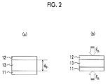
- Figs. 2A and 2B are configuration diagrams of a load sensor 10 which is connected to a correction device 20 according to this embodiment.
- Fig. 3 is a functional block diagram of the correction device 20 according to this embodiment.
- the electrostatic capacitance type pressure sensor 1 has the load sensor 10 and the correction device 20.
- the correction device 20 is connected to the load sensor 10, and corrects a detection value output from the load sensor 10.
- the load sensor 10 for use in this embodiment is an electrostatic capacitance type pressure sensor, and as shown in Figs. 2A and 2B , is constituted of two electrodes 11 and 12, and a dielectric 13 sandwiched between the two electrodes 11 and 12.
- Fig. 2A shows the state of the load sensor 10 before a load is applied
- Fig. 2B shows the state of the load sensor 10 after a load is applied.
- the dielectric 13 is elastically deformed and decreases in thickness.
- electrostatic capacitance C 0 of the load sensor 10 before the load is applied is represented by Expression (1) described below.
- the opposing area of the electrodes 11 and 12 is defined as S, and the dielectric constant of the dielectric 13 is defined as ⁇ .
- C 0 ⁇ ⁇ S / d 0
- a characteristic of the electrostatic capacitance type load sensor is that the electrostatic capacitance C N substantially increases linearly with respect to an increase in the load F N . Furthermore, it is possible to make the amount of displacement to the load large compared to a piezoelectric element type load sensor. However, in the electrostatic capacitance type load sensor, the transition of the value of electrostatic capacitance is different at the time of an increase in load and at the time of a decrease in load.
- the electrostatic capacitance of the load sensor 10 can be determined using an existing technique.
- the electrostatic capacitance of the load sensor 10 can be determined from the ratio of a frequency in a case where there is no load of the two electrodes 11 and 12 to a frequency in a case where there is a load.
- the frequency used herein is an oscillation frequency which is determined by a time constant of RC charging and a reference voltage of an operational amplifier.
- the correction device 20 corrects the difference (hereinafter, referred to as a hysteresis error) in the value of electrostatic capacitance at the time of the increase in load and at the time of the decrease in load.
- the correction device 20 includes an A/D converter 21 which converts an analog signal output from the load sensor 10 to a digital signal, a CPU 22 as an arithmetic processing device, and a memory 23 as a storage device.
- Fig. 3 is a functional block diagram of the correction device 20 according to this embodiment.
- the CPU 22 reads a program PRG and data from the memory 23, thereby realizing the functions shown in Fig. 3 .
- the correction device 20 has a specification unit 101, storage unit 102, a correction value generation unit 103, and a correction unit 104.
- the specification unit 101 specifies an ultimate load F X at the time of an increase in applied load when a load is applied to the load sensor 10.
- the ultimate load F X is not a rated load of the load sensor 10, and refers to how far the load is applied, that is, a maximum value of the applied load when a load is applied to the load sensor 10.
- the storage unit 102 stores a first function (f PEAK (F X ) for generating a maximum value of a hysteresis when the ultimate load F X is changed and a second function (F HYS (F N /F X ⁇ F MAX )) for generating a hysteresis when a rated load F MAX of the electrostatic capacitance type pressure sensor is applied.
- a first function F PEAK (F X )
- F HYS F N /F X ⁇ F MAX
- the first function (f PEAK (F X )) and the second function F HYS (F N /F X ⁇ F MAX )) are defined based on simulation results or measured values.
- the second function representing a hysteresis generated in the load sensor 10 is defined as f HYS (F N )
- the second function f HYS (F N ) is defined as the difference between electrostatic capacitance of the load sensor 10 at the time of the increase in load and electrostatic capacitance of the load sensor 10 at the time of the decrease in load, and can be thus represented by Expression (4) described below.
- f HYS F N C up F N ⁇ C down F N
- C up (F N ) is the electrostatic capacitance of the load sensor 10 under the applied load F N at the time of the increase in load.
- C down (F N ) is the electrostatic capacitance of the load sensor 10 under the applied load F N at the time of the decrease in load.
- the hysteresis Hys(F X ,F N ) can be determined from the ultimate load F X , the first function f PEAK (F X ) for generating the maximum value of the hysteresis when the ultimate load F X is changed, and the second function F HYS (F N /F X ⁇ F MAX ) representing the hysteresis at the time of the maximum ultimate load F MAX .
- f PEAK (F X ) and f HYS (F N /F X ⁇ F MAX ) should be measured and set by simulations, measurements, or the like in advance.
- the second function f HYS (F N /F X ⁇ F MAX ) is a function for generating the hysteresis of the applied load F N determined according to the ultimate load F X based on the hysteresis when the rated load F MAX of the load sensor 10 is applied.
- the second function f HYS (F N /F X ⁇ F MAX ) can be approximated by Expression (7) described below.
- A0 to An are constants and are determined by a simulation or the like.
- f HYS F N / F X ⁇ F MAX An ⁇ F MAX / F X ⁇ F N n + A n ⁇ 1 ⁇ F MAX / F X ⁇ F N n ⁇ 1 ... + A 1 ⁇ F MAX / F X ⁇ F N + A 0
- the correction value generation unit 103 generates a correction value for electrostatic capacitance actually read at the time of a decrease in load based on the ultimate load F X specified by the specification unit 101, the first function f PEAK (F X ) stored in the storage unit 102 for generating the maximum value of the hysteresis when the ultimate load F X is changed, and the second function F HYS (F N /F X ⁇ F MAX ) for generating the hysteresis when the rated load F MAX of the electrostatic capacitance type pressure sensor is applied.
- the correction unit 104 corrects the electrostatic capacitance actually read at the time of the decrease in the applied load using the correction value generated by the correction value generation unit 103. Specifically, as shown in Expression (8) described below, a read value C corr (F N ) of electrostatic capacitance after correction is calculated by subtracting the hysteresis Hys(F X ,F N ) as an error from a read value C down (F N ) of electrostatic capacitance of the load sensor 10 at the time of the decrease in load.
- C corr F N C down F N ⁇ Hys F X F N
- the read value is used as it is.
- Step S101 the specification unit 101 of the correction device 20 determines whether or not the load decreases. In a case where the load does not decrease (No in Step S101), the correction device 20 determines that the load increases, and outputs the read value of the load sensor 10 without correction (Step S102).
- the specification unit 101 of the correction device 20 determines specifies the ultimate load F X of the load applied to the load sensor 10 (Step S103).
- the correction value generation unit 103 of the correction device 20 generates the correction value based on the specified ultimate load FX, the first function f PEAK (F X ) stored in the storage unit 102 for generating the maximum value of the hysteresis when the ultimate load F X is changed, and the second function f HYS (F N /F X ⁇ F MAX ) for generating the hysteresis when the rated load F MAX of the electrostatic capacitance type pressure sensor is applied (Step S104).
- the correction unit 104 of the correction device 20 corrects the read value of the load sensor 10 based on the generated correction value (Step S105).
- the correction device 20 outputs the read value of the load sensor 10 after correction (Step S106). In a case where the operation ends (Yes in Step S107), the correction device 20 ends the operation. In a case where the operation does not end (No in Step S107), the correction device 20 continues to operate.
- the correction device 20 which corrects an output of an electrostatic capacitance type pressure sensor, in which a hysteresis as the difference between read values of electrostatic capacitance at the time of an increase in applied load and at the time of a decrease in the applied load changes, according to a maximum ultimate load of the applied load includes the specification unit 101 which specifies the ultimate load F X at the time of the increase in the applied load, the correction value generation unit 103 which generates the correction value for electrostatic capacitance actually read at the time of the decrease in load based on the ultimate load F X specified by the specification unit, the first function for generating the maximum value of the hysteresis when the ultimate load F X is changed, and the second function for generating the hysteresis when the rated load F MAX of the electrostatic capacitance type pressure sensor is applied, and the correction unit 104 which corrects the electrostatic capacitance actually read at the time of the decrease in the applied load using the correction value generated by the correction value generation
- the correction unit 104 of the correction device 20 corrects the electrostatic capacitance at the time of the decrease in load by subtracting the correction value f PEAK (F X ) ⁇ f HYS (F N /F X ⁇ F MAX ) generated by the correction value generation unit 103 from the electrostatic capacitance at the time of the decrease in load. For this reason, it is possible to correct the electrostatic capacitance at the time of the decrease in load just by subtracting the correction value generated by the correction value generation unit 103 from the electrostatic capacitance at the time of the decrease in load.
- the correction value generation unit 103 of the correction device 20 does not generate a correction value for electrostatic capacitance actually read at the time of an increase in load. For this reason, correction at the time of the increase in load is not required. As a result, it is possible to reduce a load of arithmetic processing.
- the correction method which corrects an output of an electrostatic capacitance type pressure sensor, in which a hysteresis as the difference between read values of electrostatic capacitance at the time of an increase in applied load and at the time of a decrease in the applied load changes, according to a maximum ultimate load of the applied load includes a step in which the specification unit 101 specifies the ultimate load F X at the time of the increase in the applied load, a step in which the correction value generation unit 103 generates the correction value for electrostatic capacitance actually read at the time of the decrease in load based on the ultimate load F X specified by the specification unit, the first function for generating the maximum value of the hysteresis when the ultimate load F X is changed, and the second function for generating the hysteresis when the rated load F MAX of the electrostatic capacitance type pressure sensor is applied, and a step in which the correction unit 104 corrects the electrostatic capacitance actually read at the time of the decrease in the applied load using the correction
- the program according to this embodiment which corrects an output of an electrostatic capacitance type pressure sensor, in which a hysteresis as the difference between read values of electrostatic capacitance at the time of an increase in applied load and at the time of a decrease in the applied load changes, according to a maximum ultimate load of the applied load causes a computer to execute a step of specifying the ultimate load F X at the time of the increase in the applied load, a step of generating the correction value for electrostatic capacitance actually read at the time of the decrease in load based on the specified ultimate load F X , the first function for generating the maximum value of the hysteresis when the ultimate load F X is changed, and the second function for generating the hysteresis when the rated load F MAX of the electrostatic capacitance type pressure sensor is applied, and a step of correcting the electrostatic capacitance actually read at the time of the decrease in the applied load using the correction value generated by the correction value generation unit. For this reason, it is possible to
- Fig. 5 is a configuration diagram of an electrostatic capacitance type pressure sensor 101 according to another embodiment of the invention.
- a detection unit 160 is provided at the post stage of the correction device 20 shown in Fig. 1 .
- the applied load F N a designated value to be detected is used.
- the designated value is, for example, 2.5 N.
- the detection unit 160 monitors electrostatic capacitance after correction input from the correction unit 104 of the correction device 20 shown in Fig. 3 at the time of a decrease in load and detects whether or not electrostatic capacitance after correction becomes the designated value.
Landscapes
- Physics & Mathematics (AREA)
- General Physics & Mathematics (AREA)
- Measuring Fluid Pressure (AREA)
Abstract
Description
- This application claims the benefit of Japanese Patent Application No.
2015-053140, filed on March 17, 2015 - The present invention relates to a correction device, a correction method, and a program which correct an output of an electrostatic capacitance type pressure sensor having hysteresis characteristics in which an error in a read value of electrostatic capacitance changes depending on a maximum ultimate load of an applied load at the time of an increase in the applied load and at the time of a decrease in the applied load.
- A load sensor has a difference of an output value in a process for increasing (gradually increasing) a load and in a process for decreasing (gradually decreasing) the load even if the same load is loaded. The difference is called a hysteresis error since a load cell is different depending on the history of the loaded load. In order to correct the hysteresis error, a technique which estimates gradually increasing or gradually decreasing hysteresis correction characteristics by correcting a gradually increasing or gradually decreasing error maximum value and a gradually increasing or gradually decreasing error maximum load value of the original gradually increasing and gradually decreasing hysteresis characteristics based on the ratio of the difference between a load at a turning point and a lower limit load value or an upper limit load value to the difference between the lower limit load value and the upper limit load value instead of using original gradually increasing and gradually decreasing characteristics is suggested (for example, see Japanese Unexamined Patent Application Publication No.
2006-30126 - However, in the invention disclosed in Japanese Unexamined Patent Application Publication No.
2006-30126 - The invention provides a correction device, a correction method, a program, and an electrostatic capacitance type pressure sensor capable of correcting a hysteresis error in which a maximum value has a nonlinear characteristic with respect to a change in load.
- A correction device according to an aspect of the invention which corrects an output of an electrostatic capacitance type pressure sensor, in which a hysteresis as the difference between read values of electrostatic capacitance at the time of an increase in an applied load and at the time of a decrease in the applied load changes, according to a maximum ultimate load of the applied load includes a specification unit which specifies an ultimate load at the time of the increase in the applied load, a correction value generation unit which generates a correction value for electrostatic capacitance actually read at the time of a decrease in load based on the ultimate load specified by the specification unit, a first function for generating a maximum value of the hysteresis when the ultimate load is changed, and a second function for generating a hysteresis of the applied load determined according to the ultimate load based on a hysteresis when a rated load of the electrostatic capacitance type pressure sensor is applied, and a correction unit which corrects the electrostatic capacitance actually read at the time of the decrease in the applied load using the correction value generated by the correction value generation unit.
- With this configuration, it is possible to provide a correction device capable of correcting a hysteresis error in which a maximum value has a nonlinear characteristic with respect to a change in load.
- Preferably, in a case where the applied load is FN, the ultimate load is FX, and the rated load of the electrostatic capacitance type pressure sensor is FMAX, the first function is fPEAK(FX), and the second function is fHYS(FN/FX×FMAX), the correction unit corrects the electrostatic capacitance at the time of the decrease in load by subtracting the correction value fPEAK(FX) × fHYS(FN/FX×FMAX) generated by the correction value generation unit from electrostatic capacitance at the time of the decrease in load.
- With this configuration, it is possible to correct the electrostatic capacitance at the time of the decrease in load just by subtracting the correction value generated by the correction value generation unit from the electrostatic capacitance at the time of the decrease in load.
- Preferably, the correction value generation unit does not generate a correction value for electrostatic capacitance actually read at the time of an increase in load. With this configuration, since correction at the time of the increase in load is not required, it is possible to reduce a load of arithmetic processing.
- Preferably, the second function fHYS(FN/FX×FMAX) is ([An x (FMAX/FX×FN)n + A(n-1) x (FMAX/FX×FN) (n-1) ... + A1 × (FMAX/FX×FN) + A0]). In the expression, A0 to An are constants.
- Preferably, the first function and the second function are defined based on simulation results or measured values.
- A correction method according to another aspect of the invention which corrects an output of an electrostatic capacitance type pressure sensor, in which a hysteresis as the difference between read values of electrostatic capacitance at the time of an increase in an applied load and at the time of a decrease in the applied load changes, according to a maximum ultimate load of the applied load includes a step in which a specification unit specifies an ultimate load at the time of the increase in the applied load, a step in which a correction value generation unit generates a correction value for electrostatic capacitance actually read at the time of a decrease in load based on the ultimate load specified by the specification unit, a first function for generating a maximum value of the hysteresis when the ultimate load is changed, and a second function for generating a hysteresis of the applied load determined according to the ultimate load based on a hysteresis when a rated load of the electrostatic capacitance type pressure sensor is applied, and a step in which a correction unit corrects the electrostatic capacitance actually read at the time of the decrease in the applied load using the correction value generated by the correction value generation unit.
- With this configuration, it is possible to provide a correction method capable of correcting a hysteresis error in which a maximum value has a nonlinear characteristic with respect to a change in load.
- A program according to still another aspect of the invention which corrects an output of an electrostatic capacitance type pressure sensor, in which a hysteresis as the difference between read values of electrostatic capacitance at the time of an increase in applied load and at the time of a decrease in the applied load changes, according to a maximum ultimate load of the applied load causes a computer to execute a step of specifying an ultimate load at the time of an increase in the applied load, a step of generating a correction value for electrostatic capacitance actually read at the time of a decrease in load based on the specified ultimate load, a first function for generating a maximum value of the hysteresis when the ultimate load is changed, and a second function for generating a hysteresis of the applied load determined according to the ultimate load based on a hysteresis when a rated load of the electrostatic capacitance type pressure sensor is applied, and a step of correcting the electrostatic capacitance actually read at the time of the decrease in the applied load using the correction value generated by the correction value generation unit.
- With this configuration, it is possible to provide a program capable of correcting a hysteresis error in which a maximum value has a nonlinear characteristic with respect to a change in load.
- An electrostatic capacitance type pressure sensor according to another aspect of the invention in which a hysteresis as the difference between read values of electrostatic capacitance at the time of an increase in applied load and at the time of a decrease in the applied load changes according to a maximum ultimate load of the applied load includes a specification unit which specifies an ultimate load at the time of the increase in the applied load, a correction value generation unit which generates a correction value for electrostatic capacitance actually read at the time of a decrease in load based on the ultimate load specified by the specification unit, a first function for generating a maximum value of the hysteresis when the ultimate load is changed, and a second function for generating a hysteresis of the applied load determined according to the ultimate load based on a hysteresis when a rated load of the electrostatic capacitance type pressure sensor is applied, and a correction unit which corrects the electrostatic capacitance actually read at the time of the decrease in the applied load using the correction value generated by the correction value generation unit.
- With this configuration, it is possible to detect the applied load with high accuracy by correcting the hysteresis error in which the maximum value has the nonlinear characteristic with respect to the change in load.
- Preferably, a designated value to be detected is used as the applied load, and the electrostatic capacitance type pressure sensor further includes a detection unit which detects that the electrostatic capacitance actually read at the time of the decrease in load becomes the electrostatic capacitance corrected by the correction unit at the time of the decrease in the applied load.
- With this configuration, it is possible to accurately detect that the applied load becomes the designated value to be detected at the time of the decrease in the applied load with the amount of simple arithmetic operation.
- As described above, according to the aspects of the invention, it is possible to provide a correction device, a correction method, a program, and an electrostatic capacitance type pressure sensor capable of correcting a hysteresis error in which a maximum value has a nonlinear characteristic with respect to a change in load.
-
-
Fig. 1 is a configuration diagram of an electrostatic capacitance type pressure sensor according to an embodiment of the invention. -
Figs. 2A and 2B are configuration diagrams of a load sensor which is connected to a correction device according to the embodiment of the invention. -
Fig. 3 is a functional block diagram of the correction device according to the embodiment of the invention. -
Fig. 4 is a flowchart showing the operation of the correction device according to the embodiment of the invention. -
Fig. 5 is a configuration diagram of an electrostatic capacitance type pressure sensor according to another embodiment of the invention. - Hereinafter, an embodiment of the invention will be described in detail referring to the drawings.
-
Fig. 1 is a configuration diagram of an electrostatic capacitancetype pressure sensor 1 according to the embodiment of the invention.Figs. 2A and 2B are configuration diagrams of aload sensor 10 which is connected to acorrection device 20 according to this embodiment.Fig. 3 is a functional block diagram of thecorrection device 20 according to this embodiment. - As shown in
Fig. 1 , the electrostatic capacitancetype pressure sensor 1 has theload sensor 10 and thecorrection device 20. - The
correction device 20 is connected to theload sensor 10, and corrects a detection value output from theload sensor 10. Theload sensor 10 for use in this embodiment is an electrostatic capacitance type pressure sensor, and as shown inFigs. 2A and 2B , is constituted of twoelectrodes electrodes Fig. 2A shows the state of theload sensor 10 before a load is applied, andFig. 2B shows the state of theload sensor 10 after a load is applied. As shown inFig. 2B , in a state where load FN is applied at a rated load, the dielectric 13 is elastically deformed and decreases in thickness. - If the thickness of the dielectric 13 shown in
Fig. 2A in a state where a load is not applied is defined as d0, electrostatic capacitance C0 of theload sensor 10 before the load is applied is represented by Expression (1) described below. The opposing area of theelectrodes 
- Here, if the spring constant of the dielectric 13 is defined as k, a change dN in the thickness of the dielectric 13 due to the load FN can be represented by Expression (2) described below.

- From Expressions (1) and (2) described above, the electrostatic capacitance CN in a state where the load FN is applied is represented by Expression (3) described below.

- A characteristic of the electrostatic capacitance type load sensor is that the electrostatic capacitance CN substantially increases linearly with respect to an increase in the load FN. Furthermore, it is possible to make the amount of displacement to the load large compared to a piezoelectric element type load sensor. However, in the electrostatic capacitance type load sensor, the transition of the value of electrostatic capacitance is different at the time of an increase in load and at the time of a decrease in load.
- The electrostatic capacitance of the
load sensor 10 can be determined using an existing technique. For example, the electrostatic capacitance of theload sensor 10 can be determined from the ratio of a frequency in a case where there is no load of the twoelectrodes - The
correction device 20 according to this embodiment corrects the difference (hereinafter, referred to as a hysteresis error) in the value of electrostatic capacitance at the time of the increase in load and at the time of the decrease in load. As shown inFig. 1 , thecorrection device 20 includes an A/D converter 21 which converts an analog signal output from theload sensor 10 to a digital signal, aCPU 22 as an arithmetic processing device, and amemory 23 as a storage device. -
Fig. 3 is a functional block diagram of thecorrection device 20 according to this embodiment. TheCPU 22 reads a program PRG and data from thememory 23, thereby realizing the functions shown inFig. 3 . As shown inFig. 3 , thecorrection device 20 has aspecification unit 101,storage unit 102, a correctionvalue generation unit 103, and acorrection unit 104. - The
specification unit 101 specifies an ultimate load FX at the time of an increase in applied load when a load is applied to theload sensor 10. Here, the ultimate load FX is not a rated load of theload sensor 10, and refers to how far the load is applied, that is, a maximum value of the applied load when a load is applied to theload sensor 10. - The
storage unit 102 stores a first function (fPEAK(FX) for generating a maximum value of a hysteresis when the ultimate load FX is changed and a second function (FHYS(FN/FX×FMAX)) for generating a hysteresis when a rated load FMAX of the electrostatic capacitance type pressure sensor is applied. Hereinafter, the first function (FPEAK(FX)) and the second function (fHYS(FN/FX×FMAX)) will be described. - In this embodiment, the first function (fPEAK(FX)) and the second function FHYS (FN/FX×FMAX)) are defined based on simulation results or measured values.
- First, if the second function representing a hysteresis generated in the
load sensor 10 is defined as fHYS (FN), the second function fHYS(FN) is defined as the difference between electrostatic capacitance of theload sensor 10 at the time of the increase in load and electrostatic capacitance of theload sensor 10 at the time of the decrease in load, and can be thus represented by Expression (4) described below.
- Here, Cup(FN) is the electrostatic capacitance of the
load sensor 10 under the applied load FN at the time of the increase in load. Furthermore, Cdown(FN) is the electrostatic capacitance of theload sensor 10 under the applied load FN at the time of the decrease in load. - In a case of the electrostatic capacitance type pressure sensor, since the hysteresis changes depending on the maximum ultimate load FMAX, the second function fHYS(FN) representing a hysteresis curve at the time of the ultimate load FMAX can be defined as Expression (5) described below.

- Next, if the shape of the hysteresis curve is approximated to a given curved shape without depending on the ultimate load FX, a PEAK value (maximum value) of the hysteresis when the ultimate load FX is changed is approximated by the first function fPEAK(FX), and the applied load FN is normalized by the maximum ultimate load FMAX, the following expression (6) is obtained.

- FN = 0 to FX
- FX = 0 to FMAX
- The normalization of the applied load FN by the maximum ultimate load FMAX is not statistical normalization, and means that, when the Peak load is reached (a turning point of the load), the hysteresis is zero, and thus, calculation is performed based on a hysteresis ratio = load decrease (Down) / load increase (Up) = 1.
- From Expression (6) described above, it can be understood that the hysteresis Hys(FX,FN) can be determined from the ultimate load FX, the first function fPEAK(FX) for generating the maximum value of the hysteresis when the ultimate load FX is changed, and the second function FHYS(FN/FX×FMAX) representing the hysteresis at the time of the maximum ultimate load FMAX. Note that fPEAK(FX) and fHYS(FN/FX×FMAX) should be measured and set by simulations, measurements, or the like in advance.
- The second function fHYS(FN/FX×FMAX) is a function for generating the hysteresis of the applied load FN determined according to the ultimate load FX based on the hysteresis when the rated load FMAX of the
load sensor 10 is applied. - The second function fHYS(FN/FX×FMAX) can be approximated by Expression (7) described below.
- In Expression (7), A0 to An are constants and are determined by a simulation or the like.

- With the above processing, it is possible to calculate a hysteresis component from the read electrostatic capacitance with an approximate value using a representative value. Furthermore, it is possible to reduce a load of arithmetic processing for determining the hysteresis.
- The correction
value generation unit 103 generates a correction value for electrostatic capacitance actually read at the time of a decrease in load based on the ultimate load FX specified by thespecification unit 101, the first function fPEAK(FX) stored in thestorage unit 102 for generating the maximum value of the hysteresis when the ultimate load FX is changed, and the second function FHYS (FN/FX×FMAX) for generating the hysteresis when the rated load FMAX of the electrostatic capacitance type pressure sensor is applied. - The
correction unit 104 corrects the electrostatic capacitance actually read at the time of the decrease in the applied load using the correction value generated by the correctionvalue generation unit 103. Specifically, as shown in Expression (8) described below, a read value Ccorr(FN) of electrostatic capacitance after correction is calculated by subtracting the hysteresis Hys(FX,FN) as an error from a read value Cdown(FN) of electrostatic capacitance of theload sensor 10 at the time of the decrease in load.
- If Expression (6) is substituted in Expression (8) described above, Expression (9) described below can be obtained.

- In the
correction device 20 according to this embodiment, since a hysteresis is not included in the read value of theload sensor 10 at the time of the increase in load, the read value is used as it is. - Next, the operation of the
correction device 20 will be described. - First, if a load is applied to the
load sensor 10, thespecification unit 101 of thecorrection device 20 determines whether or not the load decreases (Step S101). In a case where the load does not decrease (No in Step S101), thecorrection device 20 determines that the load increases, and outputs the read value of theload sensor 10 without correction (Step S102). - In a case where the load decreases (Yes in Step S101), the
specification unit 101 of thecorrection device 20 determines specifies the ultimate load FX of the load applied to the load sensor 10 (Step S103). Next, the correctionvalue generation unit 103 of thecorrection device 20 generates the correction value based on the specified ultimate load FX, the first function fPEAK(FX) stored in thestorage unit 102 for generating the maximum value of the hysteresis when the ultimate load FX is changed, and the second function fHYS(FN/FX×FMAX) for generating the hysteresis when the rated load FMAX of the electrostatic capacitance type pressure sensor is applied (Step S104). - Next, the
correction unit 104 of thecorrection device 20 corrects the read value of theload sensor 10 based on the generated correction value (Step S105). Next, thecorrection device 20 outputs the read value of theload sensor 10 after correction (Step S106). In a case where the operation ends (Yes in Step S107), thecorrection device 20 ends the operation. In a case where the operation does not end (No in Step S107), thecorrection device 20 continues to operate. - As described above, the
correction device 20 according to this embodiment which corrects an output of an electrostatic capacitance type pressure sensor, in which a hysteresis as the difference between read values of electrostatic capacitance at the time of an increase in applied load and at the time of a decrease in the applied load changes, according to a maximum ultimate load of the applied load includes thespecification unit 101 which specifies the ultimate load FX at the time of the increase in the applied load, the correctionvalue generation unit 103 which generates the correction value for electrostatic capacitance actually read at the time of the decrease in load based on the ultimate load FX specified by the specification unit, the first function for generating the maximum value of the hysteresis when the ultimate load FX is changed, and the second function for generating the hysteresis when the rated load FMAX of the electrostatic capacitance type pressure sensor is applied, and thecorrection unit 104 which corrects the electrostatic capacitance actually read at the time of the decrease in the applied load using the correction value generated by the correction value generation unit. For this reason, it is possible to provide a correction device capable of correcting a hysteresis error in which a maximum value has a nonlinear characteristic with respect to a change in load. - In the embodiment of the invention, the
correction unit 104 of thecorrection device 20 corrects the electrostatic capacitance at the time of the decrease in load by subtracting the correction value fPEAK(FX) × fHYS(FN/FX×FMAX) generated by the correctionvalue generation unit 103 from the electrostatic capacitance at the time of the decrease in load. For this reason, it is possible to correct the electrostatic capacitance at the time of the decrease in load just by subtracting the correction value generated by the correctionvalue generation unit 103 from the electrostatic capacitance at the time of the decrease in load. - The correction
value generation unit 103 of thecorrection device 20 according to this embodiment does not generate a correction value for electrostatic capacitance actually read at the time of an increase in load. For this reason, correction at the time of the increase in load is not required. As a result, it is possible to reduce a load of arithmetic processing. - The correction method according to this embodiment which corrects an output of an electrostatic capacitance type pressure sensor, in which a hysteresis as the difference between read values of electrostatic capacitance at the time of an increase in applied load and at the time of a decrease in the applied load changes, according to a maximum ultimate load of the applied load includes a step in which the
specification unit 101 specifies the ultimate load FX at the time of the increase in the applied load, a step in which the correctionvalue generation unit 103 generates the correction value for electrostatic capacitance actually read at the time of the decrease in load based on the ultimate load FX specified by the specification unit, the first function for generating the maximum value of the hysteresis when the ultimate load FX is changed, and the second function for generating the hysteresis when the rated load FMAX of the electrostatic capacitance type pressure sensor is applied, and a step in which thecorrection unit 104 corrects the electrostatic capacitance actually read at the time of the decrease in the applied load using the correction value generated by the correction value generation unit. For this reason, it is possible to provide a correction method capable of correcting a hysteresis error in which a maximum value has a nonlinear characteristic with respect to a change in load. - The program according to this embodiment which corrects an output of an electrostatic capacitance type pressure sensor, in which a hysteresis as the difference between read values of electrostatic capacitance at the time of an increase in applied load and at the time of a decrease in the applied load changes, according to a maximum ultimate load of the applied load causes a computer to execute a step of specifying the ultimate load FX at the time of the increase in the applied load, a step of generating the correction value for electrostatic capacitance actually read at the time of the decrease in load based on the specified ultimate load FX, the first function for generating the maximum value of the hysteresis when the ultimate load FX is changed, and the second function for generating the hysteresis when the rated load FMAX of the electrostatic capacitance type pressure sensor is applied, and a step of correcting the electrostatic capacitance actually read at the time of the decrease in the applied load using the correction value generated by the correction value generation unit. For this reason, it is possible to provide a program capable of correcting a hysteresis error in which a maximum value has a nonlinear characteristic with respect to a change in load.
- The invention is not limited to the foregoing embodiment, and can be changed in design and embodied without departing from the spirit of the invention.
-
Fig. 5 is a configuration diagram of an electrostatic capacitancetype pressure sensor 101 according to another embodiment of the invention. - As shown in
Fig. 5 , in the electrostatic capacitancetype pressure sensor 101, adetection unit 160 is provided at the post stage of thecorrection device 20 shown inFig. 1 . - In this example, as the applied load FN, a designated value to be detected is used. The designated value is, for example, 2.5 N.
- The
detection unit 160 monitors electrostatic capacitance after correction input from thecorrection unit 104 of thecorrection device 20 shown inFig. 3 at the time of a decrease in load and detects whether or not electrostatic capacitance after correction becomes the designated value. - With this configuration, it is possible to accurately detect that the applied load FN becomes the designated value to be detected with the amount of simple arithmetic operation at the time of the decrease in the applied load FN.
- It should be understood by those skilled in the art that various modifications, combinations, sub-combinations and alterations may occur depending on design requirements and other factors insofar as they are within the scope of the appended claims of the equivalents thereof.
Claims (9)
- A correction device which corrects an output of an electrostatic capacitance type pressure sensor, in which a hysteresis as the difference between read values of electrostatic capacitance at the time of an increase in applied load and at the time of a decrease in the applied load changes, according to a maximum ultimate load of the applied load, the correction device comprising:a specification unit which specifies an ultimate load at the time of the increase in the applied load;a correction value generation unit which generates a correction value for electrostatic capacitance actually read at the time of a decrease in load based on the ultimate load specified by the specification unit, a first function for generating a maximum value of the hysteresis when the ultimate load is changed, and a second function for generating a hysteresis of the applied load determined according to the ultimate load based on a hysteresis when a rated load of the electrostatic capacitance type pressure sensor is applied; anda correction unit which corrects electrostatic capacitance actually read at the time of the decrease in the applied load using the correction value generated by the correction value generation unit.
- The correction device according to claim 1,
wherein, in a case where the applied load is FN, the ultimate load is FX, and the rated load of the electrostatic capacitance type pressure sensor is FMAX,
the first function is fPEAK(FX), and
the second function is fHYS(FN/FX×FMAX)
the correction unit corrects the electrostatic capacitance at the time of the decrease in load by subtracting the correction value fPEAK(FX) × FHYS(FN/FX×FMAX) generated by the correction value generation unit from electrostatic capacitance at the time of the decrease in load. - The correction device according to claim 1 or 2,
wherein the correction value generation unit does not generate a correction value for electrostatic capacitance actually read at the time of an increase in load. - The correction device according to claim 2 or 3,
wherein the second function fHYS(FN/FX×FMA) is ([An × (FMAX/FX×FN)n + A(n-1) × (FMAX/FX×FN) (n-1) ... + A1 × (FMAX/FX×FN) + AO])
in the expression, A0 to An are constants. - The correction device according to any one of claims 1 to 4,
wherein the first function and the second function are defined based on simulation results or measured values. - A correction method which corrects an output of an electrostatic capacitance type pressure sensor, in which a hysteresis as the difference between read values of electrostatic capacitance at the time of an increase in applied load and at the time of a decrease in the applied load changes, according to a maximum ultimate load of the applied load, the correction method comprising:a step in which a specification unit specifies an ultimate load at the time of the increase in the applied load;a step in which a correction value generation unit generates a correction value for electrostatic capacitance actually read at the time of a decrease in load based on the ultimate load specified by the specification unit, a first function for generating a maximum value of the hysteresis when the ultimate load is changed, and a second function for generating a hysteresis of the applied load determined according to the ultimate load based on a hysteresis when a rated load of the electrostatic capacitance type pressure sensor is applied; anda step in which a correction unit corrects electrostatic capacitance actually read at the time of the decrease in the applied load using the correction value generated by the correction value generation unit.
- A program which corrects an output of an electrostatic capacitance type pressure sensor, in which a hysteresis as the difference between read values of electrostatic capacitance at the time of an increase in applied load and at the time of a decrease in the applied load changes, according to a maximum ultimate load of the applied load, the program causing a computer to execute:a step of specifying an ultimate load at the time of an increase in the applied load;a step of generating a correction value for electrostatic capacitance actually read at the time of a decrease in load based on the specified ultimate load, a first function for generating a maximum value of the hysteresis when the ultimate load is changed, and a second function for generating a hysteresis of the applied load determined according to the ultimate load based on a hysteresis when a rated load of the electrostatic capacitance type pressure sensor is applied; anda step of correcting electrostatic capacitance actually read at the time of the decrease in the applied load using the correction value generated by the correction value generation unit.
- An electrostatic capacitance type pressure sensor in which a hysteresis as the difference between read values of electrostatic capacitance at the time of an increase in applied load and at the time of a decrease in the applied load changes according to a maximum ultimate load of the applied load, the electrostatic capacitance type pressure sensor comprising:a specification unit which specifies an ultimate load at the time of the increase in the applied load;a correction value generation unit which generates a correction value for electrostatic capacitance actually read at the time of a decrease in load based on the ultimate load specified by the specification unit, a first function for generating a maximum value of the hysteresis when the ultimate load is changed, and a second function for generating a hysteresis of the applied load determined according to the ultimate load based on a hysteresis when a rated load of the electrostatic capacitance type pressure sensor is applied; anda correction unit which corrects electrostatic capacitance actually read at the time of the decrease in the applied load using the correction value generated by the correction value generation unit.
- The electrostatic capacitance type pressure sensor according to claim 8,
wherein a designated value to be detected is used as the applied load, and
the electrostatic capacitance type pressure sensor further comprises:a detection unit which detects that the electrostatic capacitance actually read at the time of the decrease in load becomes the electrostatic capacitance corrected by the correction unit at the time of the decrease in the applied load.
Applications Claiming Priority (1)
| Application Number | Priority Date | Filing Date | Title |
|---|---|---|---|
| JP2015053140A JP6417246B2 (en) | 2015-03-17 | 2015-03-17 | Correction apparatus, correction method, program, and capacitive pressure sensor |
Publications (2)
| Publication Number | Publication Date |
|---|---|
| EP3070452A1 true EP3070452A1 (en) | 2016-09-21 |
| EP3070452B1 EP3070452B1 (en) | 2018-12-05 |
Family
ID=55910087
Family Applications (1)
| Application Number | Title | Priority Date | Filing Date |
|---|---|---|---|
| EP16160457.4A Active EP3070452B1 (en) | 2015-03-17 | 2016-03-15 | Correction device, correction method, program, and electrostatic capacitance type pressure sensor |
Country Status (3)
| Country | Link |
|---|---|
| EP (1) | EP3070452B1 (en) |
| JP (1) | JP6417246B2 (en) |
| CN (1) | CN105987787B (en) |
Cited By (1)
| Publication number | Priority date | Publication date | Assignee | Title |
|---|---|---|---|---|
| CN119845486A (en) * | 2025-03-19 | 2025-04-18 | 西安西自仪检测技术有限公司 | Comprehensive detection system and method for petroleum logging sensor |
Citations (2)
| Publication number | Priority date | Publication date | Assignee | Title |
|---|---|---|---|---|
| GB1479192A (en) * | 1975-09-19 | 1977-07-06 | Avery Ltd W | Hysteresis correction |
| JP2006030126A (en) | 2004-07-21 | 2006-02-02 | Yamato Scale Co Ltd | Hysteresis error correction device |
Family Cites Families (5)
| Publication number | Priority date | Publication date | Assignee | Title |
|---|---|---|---|---|
| JP3428319B2 (en) * | 1996-09-30 | 2003-07-22 | オムロン株式会社 | Capacitance detection circuit and capacitance type sensor device |
| JP4347548B2 (en) * | 2002-07-18 | 2009-10-21 | 大和製衡株式会社 | Hysteresis error correction device |
| EP2357460A1 (en) * | 2008-11-21 | 2011-08-17 | Takano Co., Ltd. | Capacitive dynamic quantity sensor element and dynamic quantity sensor |
| EP2755005A3 (en) * | 2013-01-09 | 2017-01-25 | Auto Industrial Co., Ltd. | Output specification calibrating apparatus for capacitive pressure sensor |
| JP6093622B2 (en) * | 2013-03-29 | 2017-03-08 | 大和製衡株式会社 | Hysteresis error compensation device, load sensor, weighing device, and hysteresis error compensation method |
-
2015
- 2015-03-17 JP JP2015053140A patent/JP6417246B2/en active Active
-
2016
- 2016-03-15 CN CN201610147704.0A patent/CN105987787B/en active Active
- 2016-03-15 EP EP16160457.4A patent/EP3070452B1/en active Active
Patent Citations (2)
| Publication number | Priority date | Publication date | Assignee | Title |
|---|---|---|---|---|
| GB1479192A (en) * | 1975-09-19 | 1977-07-06 | Avery Ltd W | Hysteresis correction |
| JP2006030126A (en) | 2004-07-21 | 2006-02-02 | Yamato Scale Co Ltd | Hysteresis error correction device |
Cited By (1)
| Publication number | Priority date | Publication date | Assignee | Title |
|---|---|---|---|---|
| CN119845486A (en) * | 2025-03-19 | 2025-04-18 | 西安西自仪检测技术有限公司 | Comprehensive detection system and method for petroleum logging sensor |
Also Published As
| Publication number | Publication date |
|---|---|
| CN105987787B (en) | 2019-11-05 |
| JP2016173291A (en) | 2016-09-29 |
| CN105987787A (en) | 2016-10-05 |
| JP6417246B2 (en) | 2018-10-31 |
| EP3070452B1 (en) | 2018-12-05 |
Similar Documents
| Publication | Publication Date | Title |
|---|---|---|
| US10352786B2 (en) | Pressing sensor and electronic device | |
| KR101734796B1 (en) | Pressure detection device, method for controlling pressure detection device, and program | |
| JP7552995B2 (en) | Apparatus and method for calculating charge capacity of energy storage system | |
| EP2120134A1 (en) | Display terminal with touch panel function and calibration method | |
| EP3144655A1 (en) | Reduction of non-linearity errors in automotive pressure sensors | |
| KR20190037985A (en) | Apparatus and method for calculating battery pack SOH | |
| CN108604136A (en) | Determine the changed method of induction electrode initial distance | |
| EP2790091A2 (en) | Input device, computer-readable recording medium, and method for receiving input | |
| CN109196319B (en) | Digital creep and drift correction | |
| EP3070452B1 (en) | Correction device, correction method, program, and electrostatic capacitance type pressure sensor | |
| KR101066509B1 (en) | Foreclosure transmitter | |
| JP4752528B2 (en) | Strain gauge type load cell and electronic scale using the same | |
| US10606407B2 (en) | Force-based touch interface device and method for correcting the force-based touch interface device | |
| US10775922B2 (en) | Input device having load calculation method for a plurality of pressed positions | |
| US20120179400A1 (en) | Compensating for hysteresis | |
| JP4347548B2 (en) | Hysteresis error correction device | |
| US20170299623A1 (en) | Inertial force sensor | |
| CN110073173B (en) | Signal processing device and signal processing method | |
| US20230200252A1 (en) | Piezoelectric system | |
| JP7731260B2 (en) | Input device and control method for input device | |
| JP6666575B2 (en) | AC power regulator | |
| US12455200B2 (en) | Electric signal reconstruction system and method | |
| CN108318178B (en) | pressure gauge | |
| JP7095461B2 (en) | Capacitance sensor and operation input detector for vehicles | |
| CN121217139A (en) | Methods and apparatus for calculating key recognition range, key recognition methods and equipment |
Legal Events
| Date | Code | Title | Description |
|---|---|---|---|
| PUAI | Public reference made under article 153(3) epc to a published international application that has entered the european phase |
Free format text: ORIGINAL CODE: 0009012 |
|
| AK | Designated contracting states |
Kind code of ref document: A1 Designated state(s): AL AT BE BG CH CY CZ DE DK EE ES FI FR GB GR HR HU IE IS IT LI LT LU LV MC MK MT NL NO PL PT RO RS SE SI SK SM TR |
|
| AX | Request for extension of the european patent |
Extension state: BA ME |
|
| STAA | Information on the status of an ep patent application or granted ep patent |
Free format text: STATUS: REQUEST FOR EXAMINATION WAS MADE |
|
| 17P | Request for examination filed |
Effective date: 20170125 |
|
| RBV | Designated contracting states (corrected) |
Designated state(s): AL AT BE BG CH CY CZ DE DK EE ES FI FR GB GR HR HU IE IS IT LI LT LU LV MC MK MT NL NO PL PT RO RS SE SI SK SM TR |
|
| STAA | Information on the status of an ep patent application or granted ep patent |
Free format text: STATUS: EXAMINATION IS IN PROGRESS |
|
| 17Q | First examination report despatched |
Effective date: 20170622 |
|
| GRAP | Despatch of communication of intention to grant a patent |
Free format text: ORIGINAL CODE: EPIDOSNIGR1 |
|
| STAA | Information on the status of an ep patent application or granted ep patent |
Free format text: STATUS: GRANT OF PATENT IS INTENDED |
|
| INTG | Intention to grant announced |
Effective date: 20180717 |
|
| GRAS | Grant fee paid |
Free format text: ORIGINAL CODE: EPIDOSNIGR3 |
|
| GRAA | (expected) grant |
Free format text: ORIGINAL CODE: 0009210 |
|
| STAA | Information on the status of an ep patent application or granted ep patent |
Free format text: STATUS: THE PATENT HAS BEEN GRANTED |
|
| AK | Designated contracting states |
Kind code of ref document: B1 Designated state(s): AL AT BE BG CH CY CZ DE DK EE ES FI FR GB GR HR HU IE IS IT LI LT LU LV MC MK MT NL NO PL PT RO RS SE SI SK SM TR |
|
| REG | Reference to a national code |
Ref country code: GB Ref legal event code: FG4D |
|
| REG | Reference to a national code |
Ref country code: CH Ref legal event code: EP |
|
| REG | Reference to a national code |
Ref country code: AT Ref legal event code: REF Ref document number: 1073667 Country of ref document: AT Kind code of ref document: T Effective date: 20181215 |
|
| REG | Reference to a national code |
Ref country code: DE Ref legal event code: R096 Ref document number: 602016007711 Country of ref document: DE |
|
| REG | Reference to a national code |
Ref country code: IE Ref legal event code: FG4D |
|
| REG | Reference to a national code |
Ref country code: DE Ref legal event code: R081 Ref document number: 602016007711 Country of ref document: DE Owner name: ALPS ALPINE CO., LTD., JP Free format text: FORMER OWNER: ALPS ELECTRIC CO., LTD, TOKYO, JP |
|
| REG | Reference to a national code |
Ref country code: NL Ref legal event code: MP Effective date: 20181205 |
|
| REG | Reference to a national code |
Ref country code: AT Ref legal event code: MK05 Ref document number: 1073667 Country of ref document: AT Kind code of ref document: T Effective date: 20181205 |
|
| REG | Reference to a national code |
Ref country code: LT Ref legal event code: MG4D |
|
| PG25 | Lapsed in a contracting state [announced via postgrant information from national office to epo] |
Ref country code: FI Free format text: LAPSE BECAUSE OF FAILURE TO SUBMIT A TRANSLATION OF THE DESCRIPTION OR TO PAY THE FEE WITHIN THE PRESCRIBED TIME-LIMIT Effective date: 20181205 Ref country code: NO Free format text: LAPSE BECAUSE OF FAILURE TO SUBMIT A TRANSLATION OF THE DESCRIPTION OR TO PAY THE FEE WITHIN THE PRESCRIBED TIME-LIMIT Effective date: 20190305 Ref country code: LV Free format text: LAPSE BECAUSE OF FAILURE TO SUBMIT A TRANSLATION OF THE DESCRIPTION OR TO PAY THE FEE WITHIN THE PRESCRIBED TIME-LIMIT Effective date: 20181205 Ref country code: AT Free format text: LAPSE BECAUSE OF FAILURE TO SUBMIT A TRANSLATION OF THE DESCRIPTION OR TO PAY THE FEE WITHIN THE PRESCRIBED TIME-LIMIT Effective date: 20181205 Ref country code: ES Free format text: LAPSE BECAUSE OF FAILURE TO SUBMIT A TRANSLATION OF THE DESCRIPTION OR TO PAY THE FEE WITHIN THE PRESCRIBED TIME-LIMIT Effective date: 20181205 Ref country code: LT Free format text: LAPSE BECAUSE OF FAILURE TO SUBMIT A TRANSLATION OF THE DESCRIPTION OR TO PAY THE FEE WITHIN THE PRESCRIBED TIME-LIMIT Effective date: 20181205 Ref country code: BG Free format text: LAPSE BECAUSE OF FAILURE TO SUBMIT A TRANSLATION OF THE DESCRIPTION OR TO PAY THE FEE WITHIN THE PRESCRIBED TIME-LIMIT Effective date: 20190305 Ref country code: HR Free format text: LAPSE BECAUSE OF FAILURE TO SUBMIT A TRANSLATION OF THE DESCRIPTION OR TO PAY THE FEE WITHIN THE PRESCRIBED TIME-LIMIT Effective date: 20181205 |
|
| PG25 | Lapsed in a contracting state [announced via postgrant information from national office to epo] |
Ref country code: AL Free format text: LAPSE BECAUSE OF FAILURE TO SUBMIT A TRANSLATION OF THE DESCRIPTION OR TO PAY THE FEE WITHIN THE PRESCRIBED TIME-LIMIT Effective date: 20181205 Ref country code: SE Free format text: LAPSE BECAUSE OF FAILURE TO SUBMIT A TRANSLATION OF THE DESCRIPTION OR TO PAY THE FEE WITHIN THE PRESCRIBED TIME-LIMIT Effective date: 20181205 Ref country code: RS Free format text: LAPSE BECAUSE OF FAILURE TO SUBMIT A TRANSLATION OF THE DESCRIPTION OR TO PAY THE FEE WITHIN THE PRESCRIBED TIME-LIMIT Effective date: 20181205 Ref country code: GR Free format text: LAPSE BECAUSE OF FAILURE TO SUBMIT A TRANSLATION OF THE DESCRIPTION OR TO PAY THE FEE WITHIN THE PRESCRIBED TIME-LIMIT Effective date: 20190306 |
|
| PG25 | Lapsed in a contracting state [announced via postgrant information from national office to epo] |
Ref country code: NL Free format text: LAPSE BECAUSE OF FAILURE TO SUBMIT A TRANSLATION OF THE DESCRIPTION OR TO PAY THE FEE WITHIN THE PRESCRIBED TIME-LIMIT Effective date: 20181205 |
|
| PG25 | Lapsed in a contracting state [announced via postgrant information from national office to epo] |
Ref country code: CZ Free format text: LAPSE BECAUSE OF FAILURE TO SUBMIT A TRANSLATION OF THE DESCRIPTION OR TO PAY THE FEE WITHIN THE PRESCRIBED TIME-LIMIT Effective date: 20181205 Ref country code: IT Free format text: LAPSE BECAUSE OF FAILURE TO SUBMIT A TRANSLATION OF THE DESCRIPTION OR TO PAY THE FEE WITHIN THE PRESCRIBED TIME-LIMIT Effective date: 20181205 Ref country code: PL Free format text: LAPSE BECAUSE OF FAILURE TO SUBMIT A TRANSLATION OF THE DESCRIPTION OR TO PAY THE FEE WITHIN THE PRESCRIBED TIME-LIMIT Effective date: 20181205 Ref country code: PT Free format text: LAPSE BECAUSE OF FAILURE TO SUBMIT A TRANSLATION OF THE DESCRIPTION OR TO PAY THE FEE WITHIN THE PRESCRIBED TIME-LIMIT Effective date: 20190405 |
|
| PG25 | Lapsed in a contracting state [announced via postgrant information from national office to epo] |
Ref country code: EE Free format text: LAPSE BECAUSE OF FAILURE TO SUBMIT A TRANSLATION OF THE DESCRIPTION OR TO PAY THE FEE WITHIN THE PRESCRIBED TIME-LIMIT Effective date: 20181205 Ref country code: SM Free format text: LAPSE BECAUSE OF FAILURE TO SUBMIT A TRANSLATION OF THE DESCRIPTION OR TO PAY THE FEE WITHIN THE PRESCRIBED TIME-LIMIT Effective date: 20181205 Ref country code: IS Free format text: LAPSE BECAUSE OF FAILURE TO SUBMIT A TRANSLATION OF THE DESCRIPTION OR TO PAY THE FEE WITHIN THE PRESCRIBED TIME-LIMIT Effective date: 20190405 Ref country code: RO Free format text: LAPSE BECAUSE OF FAILURE TO SUBMIT A TRANSLATION OF THE DESCRIPTION OR TO PAY THE FEE WITHIN THE PRESCRIBED TIME-LIMIT Effective date: 20181205 Ref country code: SK Free format text: LAPSE BECAUSE OF FAILURE TO SUBMIT A TRANSLATION OF THE DESCRIPTION OR TO PAY THE FEE WITHIN THE PRESCRIBED TIME-LIMIT Effective date: 20181205 |
|
| REG | Reference to a national code |
Ref country code: DE Ref legal event code: R097 Ref document number: 602016007711 Country of ref document: DE |
|
| PLBE | No opposition filed within time limit |
Free format text: ORIGINAL CODE: 0009261 |
|
| STAA | Information on the status of an ep patent application or granted ep patent |
Free format text: STATUS: NO OPPOSITION FILED WITHIN TIME LIMIT |
|
| PG25 | Lapsed in a contracting state [announced via postgrant information from national office to epo] |
Ref country code: DK Free format text: LAPSE BECAUSE OF FAILURE TO SUBMIT A TRANSLATION OF THE DESCRIPTION OR TO PAY THE FEE WITHIN THE PRESCRIBED TIME-LIMIT Effective date: 20181205 Ref country code: MC Free format text: LAPSE BECAUSE OF FAILURE TO SUBMIT A TRANSLATION OF THE DESCRIPTION OR TO PAY THE FEE WITHIN THE PRESCRIBED TIME-LIMIT Effective date: 20181205 Ref country code: SI Free format text: LAPSE BECAUSE OF FAILURE TO SUBMIT A TRANSLATION OF THE DESCRIPTION OR TO PAY THE FEE WITHIN THE PRESCRIBED TIME-LIMIT Effective date: 20181205 |
|
| REG | Reference to a national code |
Ref country code: CH Ref legal event code: PL |
|
| 26N | No opposition filed |
Effective date: 20190906 |
|
| PG25 | Lapsed in a contracting state [announced via postgrant information from national office to epo] |
Ref country code: LU Free format text: LAPSE BECAUSE OF NON-PAYMENT OF DUE FEES Effective date: 20190315 |
|
| REG | Reference to a national code |
Ref country code: BE Ref legal event code: MM Effective date: 20190331 |
|
| PG25 | Lapsed in a contracting state [announced via postgrant information from national office to epo] |
Ref country code: IE Free format text: LAPSE BECAUSE OF NON-PAYMENT OF DUE FEES Effective date: 20190315 Ref country code: LI Free format text: LAPSE BECAUSE OF NON-PAYMENT OF DUE FEES Effective date: 20190331 Ref country code: CH Free format text: LAPSE BECAUSE OF NON-PAYMENT OF DUE FEES Effective date: 20190331 |
|
| PG25 | Lapsed in a contracting state [announced via postgrant information from national office to epo] |
Ref country code: BE Free format text: LAPSE BECAUSE OF NON-PAYMENT OF DUE FEES Effective date: 20190331 |
|
| PG25 | Lapsed in a contracting state [announced via postgrant information from national office to epo] |
Ref country code: TR Free format text: LAPSE BECAUSE OF FAILURE TO SUBMIT A TRANSLATION OF THE DESCRIPTION OR TO PAY THE FEE WITHIN THE PRESCRIBED TIME-LIMIT Effective date: 20181205 |
|
| PGFP | Annual fee paid to national office [announced via postgrant information from national office to epo] |
Ref country code: GB Payment date: 20200323 Year of fee payment: 5 |
|
| PG25 | Lapsed in a contracting state [announced via postgrant information from national office to epo] |
Ref country code: MT Free format text: LAPSE BECAUSE OF NON-PAYMENT OF DUE FEES Effective date: 20190315 |
|
| PGFP | Annual fee paid to national office [announced via postgrant information from national office to epo] |
Ref country code: FR Payment date: 20200320 Year of fee payment: 5 |
|
| PG25 | Lapsed in a contracting state [announced via postgrant information from national office to epo] |
Ref country code: CY Free format text: LAPSE BECAUSE OF FAILURE TO SUBMIT A TRANSLATION OF THE DESCRIPTION OR TO PAY THE FEE WITHIN THE PRESCRIBED TIME-LIMIT Effective date: 20181205 |
|
| PG25 | Lapsed in a contracting state [announced via postgrant information from national office to epo] |
Ref country code: HU Free format text: LAPSE BECAUSE OF FAILURE TO SUBMIT A TRANSLATION OF THE DESCRIPTION OR TO PAY THE FEE WITHIN THE PRESCRIBED TIME-LIMIT; INVALID AB INITIO Effective date: 20160315 |
|
| GBPC | Gb: european patent ceased through non-payment of renewal fee |
Effective date: 20210315 |
|
| PG25 | Lapsed in a contracting state [announced via postgrant information from national office to epo] |
Ref country code: GB Free format text: LAPSE BECAUSE OF NON-PAYMENT OF DUE FEES Effective date: 20210315 Ref country code: FR Free format text: LAPSE BECAUSE OF NON-PAYMENT OF DUE FEES Effective date: 20210331 |
|
| PG25 | Lapsed in a contracting state [announced via postgrant information from national office to epo] |
Ref country code: MK Free format text: LAPSE BECAUSE OF FAILURE TO SUBMIT A TRANSLATION OF THE DESCRIPTION OR TO PAY THE FEE WITHIN THE PRESCRIBED TIME-LIMIT Effective date: 20181205 |
|
| PGFP | Annual fee paid to national office [announced via postgrant information from national office to epo] |
Ref country code: DE Payment date: 20260319 Year of fee payment: 11 |