EP3070357A1 - Method for manufacturing telescopic shaft - Google Patents
Method for manufacturing telescopic shaft Download PDFInfo
- Publication number
- EP3070357A1 EP3070357A1 EP14860825.0A EP14860825A EP3070357A1 EP 3070357 A1 EP3070357 A1 EP 3070357A1 EP 14860825 A EP14860825 A EP 14860825A EP 3070357 A1 EP3070357 A1 EP 3070357A1
- Authority
- EP
- European Patent Office
- Prior art keywords
- coating layer
- shaft
- resin coating
- broaching
- male
- Prior art date
- Legal status (The legal status is an assumption and is not a legal conclusion. Google has not performed a legal analysis and makes no representation as to the accuracy of the status listed.)
- Granted
Links
- 238000000034 method Methods 0.000 title claims abstract description 20
- 238000004519 manufacturing process Methods 0.000 title claims abstract description 14
- 229920005989 resin Polymers 0.000 claims abstract description 138
- 239000011347 resin Substances 0.000 claims abstract description 138
- 239000011247 coating layer Substances 0.000 claims abstract description 112
- 239000011248 coating agent Substances 0.000 claims abstract description 57
- 238000000576 coating method Methods 0.000 claims abstract description 57
- 238000001816 cooling Methods 0.000 claims abstract description 36
- 239000000463 material Substances 0.000 claims abstract description 31
- 239000000843 powder Substances 0.000 claims abstract description 30
- 239000012530 fluid Substances 0.000 claims abstract description 6
- 238000002844 melting Methods 0.000 claims description 33
- 230000008018 melting Effects 0.000 claims description 33
- 229920000305 Nylon 6,10 Polymers 0.000 description 11
- 239000011800 void material Substances 0.000 description 10
- 230000000052 comparative effect Effects 0.000 description 6
- 239000003638 chemical reducing agent Substances 0.000 description 3
- 238000001514 detection method Methods 0.000 description 3
- 239000004696 Poly ether ether ketone Substances 0.000 description 2
- 239000004697 Polyetherimide Substances 0.000 description 2
- 239000004734 Polyphenylene sulfide Substances 0.000 description 2
- 238000007664 blowing Methods 0.000 description 2
- 229920006351 engineering plastic Polymers 0.000 description 2
- 239000010410 layer Substances 0.000 description 2
- 238000001000 micrograph Methods 0.000 description 2
- 229920002492 poly(sulfone) Polymers 0.000 description 2
- 229920001230 polyarylate Polymers 0.000 description 2
- 229920002530 polyetherether ketone Polymers 0.000 description 2
- 229920001601 polyetherimide Polymers 0.000 description 2
- 229920000069 polyphenylene sulfide Polymers 0.000 description 2
- 229920005992 thermoplastic resin Polymers 0.000 description 2
- YCKRFDGAMUMZLT-UHFFFAOYSA-N Fluorine atom Chemical compound [F] YCKRFDGAMUMZLT-UHFFFAOYSA-N 0.000 description 1
- 229920000106 Liquid crystal polymer Polymers 0.000 description 1
- 239000004977 Liquid-crystal polymers (LCPs) Substances 0.000 description 1
- 229920000571 Nylon 11 Polymers 0.000 description 1
- 229920000299 Nylon 12 Polymers 0.000 description 1
- 229920000572 Nylon 6/12 Polymers 0.000 description 1
- 229920012266 Poly(ether sulfone) PES Polymers 0.000 description 1
- 239000004642 Polyimide Substances 0.000 description 1
- 230000003247 decreasing effect Effects 0.000 description 1
- 230000007547 defect Effects 0.000 description 1
- 238000006073 displacement reaction Methods 0.000 description 1
- 229910052731 fluorine Inorganic materials 0.000 description 1
- 239000011737 fluorine Substances 0.000 description 1
- 238000012986 modification Methods 0.000 description 1
- 230000004048 modification Effects 0.000 description 1
- 239000003960 organic solvent Substances 0.000 description 1
- 238000005498 polishing Methods 0.000 description 1
- 229920001721 polyimide Polymers 0.000 description 1
- 230000035939 shock Effects 0.000 description 1
Images



Classifications
-
- C—CHEMISTRY; METALLURGY
- C09—DYES; PAINTS; POLISHES; NATURAL RESINS; ADHESIVES; COMPOSITIONS NOT OTHERWISE PROVIDED FOR; APPLICATIONS OF MATERIALS NOT OTHERWISE PROVIDED FOR
- C09D—COATING COMPOSITIONS, e.g. PAINTS, VARNISHES OR LACQUERS; FILLING PASTES; CHEMICAL PAINT OR INK REMOVERS; INKS; CORRECTING FLUIDS; WOODSTAINS; PASTES OR SOLIDS FOR COLOURING OR PRINTING; USE OF MATERIALS THEREFOR
- C09D177/00—Coating compositions based on polyamides obtained by reactions forming a carboxylic amide link in the main chain; Coating compositions based on derivatives of such polymers
-
- B—PERFORMING OPERATIONS; TRANSPORTING
- B05—SPRAYING OR ATOMISING IN GENERAL; APPLYING FLUENT MATERIALS TO SURFACES, IN GENERAL
- B05D—PROCESSES FOR APPLYING FLUENT MATERIALS TO SURFACES, IN GENERAL
- B05D1/00—Processes for applying liquids or other fluent materials
- B05D1/18—Processes for applying liquids or other fluent materials performed by dipping
- B05D1/22—Processes for applying liquids or other fluent materials performed by dipping using fluidised-bed technique
-
- C—CHEMISTRY; METALLURGY
- C09—DYES; PAINTS; POLISHES; NATURAL RESINS; ADHESIVES; COMPOSITIONS NOT OTHERWISE PROVIDED FOR; APPLICATIONS OF MATERIALS NOT OTHERWISE PROVIDED FOR
- C09D—COATING COMPOSITIONS, e.g. PAINTS, VARNISHES OR LACQUERS; FILLING PASTES; CHEMICAL PAINT OR INK REMOVERS; INKS; CORRECTING FLUIDS; WOODSTAINS; PASTES OR SOLIDS FOR COLOURING OR PRINTING; USE OF MATERIALS THEREFOR
- C09D201/00—Coating compositions based on unspecified macromolecular compounds
-
- C—CHEMISTRY; METALLURGY
- C09—DYES; PAINTS; POLISHES; NATURAL RESINS; ADHESIVES; COMPOSITIONS NOT OTHERWISE PROVIDED FOR; APPLICATIONS OF MATERIALS NOT OTHERWISE PROVIDED FOR
- C09D—COATING COMPOSITIONS, e.g. PAINTS, VARNISHES OR LACQUERS; FILLING PASTES; CHEMICAL PAINT OR INK REMOVERS; INKS; CORRECTING FLUIDS; WOODSTAINS; PASTES OR SOLIDS FOR COLOURING OR PRINTING; USE OF MATERIALS THEREFOR
- C09D5/00—Coating compositions, e.g. paints, varnishes or lacquers, characterised by their physical nature or the effects produced; Filling pastes
- C09D5/03—Powdery paints
-
- F—MECHANICAL ENGINEERING; LIGHTING; HEATING; WEAPONS; BLASTING
- F16—ENGINEERING ELEMENTS AND UNITS; GENERAL MEASURES FOR PRODUCING AND MAINTAINING EFFECTIVE FUNCTIONING OF MACHINES OR INSTALLATIONS; THERMAL INSULATION IN GENERAL
- F16D—COUPLINGS FOR TRANSMITTING ROTATION; CLUTCHES; BRAKES
- F16D3/00—Yielding couplings, i.e. with means permitting movement between the connected parts during the drive
- F16D3/02—Yielding couplings, i.e. with means permitting movement between the connected parts during the drive adapted to specific functions
- F16D3/06—Yielding couplings, i.e. with means permitting movement between the connected parts during the drive adapted to specific functions specially adapted to allow axial displacement
-
- F—MECHANICAL ENGINEERING; LIGHTING; HEATING; WEAPONS; BLASTING
- F16—ENGINEERING ELEMENTS AND UNITS; GENERAL MEASURES FOR PRODUCING AND MAINTAINING EFFECTIVE FUNCTIONING OF MACHINES OR INSTALLATIONS; THERMAL INSULATION IN GENERAL
- F16D—COUPLINGS FOR TRANSMITTING ROTATION; CLUTCHES; BRAKES
- F16D2250/00—Manufacturing; Assembly
- F16D2250/0038—Surface treatment
- F16D2250/0046—Coating
-
- F—MECHANICAL ENGINEERING; LIGHTING; HEATING; WEAPONS; BLASTING
- F16—ENGINEERING ELEMENTS AND UNITS; GENERAL MEASURES FOR PRODUCING AND MAINTAINING EFFECTIVE FUNCTIONING OF MACHINES OR INSTALLATIONS; THERMAL INSULATION IN GENERAL
- F16D—COUPLINGS FOR TRANSMITTING ROTATION; CLUTCHES; BRAKES
- F16D2300/00—Special features for couplings or clutches
- F16D2300/10—Surface characteristics; Details related to material surfaces
Definitions
- the present invention relates to a method for manufacturing a telescopic shaft used as an intermediate shaft or the like, which includes a male shaft connected to be slidable in an axial direction and a cylindrical female shaft, and which transmits a steering force, for example, in a vehicle steering apparatus.
- An intermediate shaft of a vehicle steering apparatus is configured of a telescopic shaft in which, for example, a male shaft and a cylindrical female shaft are telescopically connected in an axial direction by splines in mesh (spline fitting).
- the outer circumferential surface of the male shaft or the inner circumferential surface of the female shaft, which has splines, is coated with a resin coating layer with which a clearance between both the shafts is filled so as to reduce rattling or to reduce loosening of a steering wheel during a steering operation (for example, see PTLs 1 and 2).
- a powder-fluidized bed dip method As a method for forming the resin coating layer, a powder-fluidized bed dip method is known. Since an organic solvent is not used in the powder-fluidized bed dip method, it is advantageous to reduce the impact on the environment.
- a powder coating material containing a base resin (thermoplastic resin) as a base of the resin coating layer is first prepared, and the powder coating material enters a state of being suspended or fluidized in a fluid bath by blowing air or the like therein.
- a base resin thermoplastic resin
- the powder coating material is attached to the outer circumferential surface of the male shaft or the inner circumferential surface of the female shaft (hereinafter, in some cases, also referred to as an "attachment target surface") and is melted and spread, and then, is further cooled and solidified such that a resin coating layer is formed.
- polyamide 11, polyamide 12, or the like which can form a resin coating layer good in fluidity when melting and good in slidability or the like, is appropriately used.
- polyamide 610 or the like which is better in heat resistance than current materials, and is also good in friction and wear properties, slidability, or the like.
- the resin coating layer is solidified, thereby contracting in series from the surface, and, particularly, a region having a low density is locally formed in a thick portion, near an interface of the attachment target surface. Then, when the density of the region is lower than a limit, a vacuum void is formed.
- the thick resin coating layer is cooled and then, is finished by broaching or the like in accordance with the clearance between the male shaft and the female shaft; however, when the vacuum void is formed in the inner section, the void is exposed as a defect during polishing and results in reducing strength or the like of the resin coating layer.
- An object of the present invention is to provide a manufacturing method in which a telescopic shaft having a continuous resin coating layer without a vacuum void, which is formed on an outer circumferential surface of a male shaft or an inner circumferential surface of a female shaft, can be manufactured by a powder-fluidized bed dip method using a powder coating material.
- a method for manufacturing a telescopic shaft including a male shaft and a cylindrical female shaft slidably connected to each other in an axial direction thereof, in which an outer circumferential surface of the male shaft or an inner circumferential surface of the female shaft is coated with a resin coating layer
- the method including: a coating step of attaching, by a fluid bed dip method, a powder coating material on the outer circumferential surface of the male shaft or the inner circumferential surface of the female shaft which is heated in advance and of forming the resin coating layer; a broaching step of making the resin coating layer thin by broaching before cooling of the formed resin coating layer is completed; and a cooling step of cooling the thin resin coating layer.
- the resin coating layer may be subjected to the broaching in a temperature which is equal to or higher than a temperature below a melting point of the base resin contained in the powder coating material by 30°C and is equal to or lower than the melting point.
- the resin coating layer may be formed to have a thickness of 100 ⁇ m to 1.5 mm.
- Fig. 1 is a view schematically showing an example of an electric power steering apparatus including an intermediate shaft which is assembled as a telescopic shaft.
- an electric power steering apparatus 1 includes a steering shaft 3 that is connected to a steering wheel 2 so as to be integrally rotatable along with the steering wheel, an intermediate shaft 5 connected to the steering shaft 3 through a universal joint 4, a pinion shaft 7 connected to the intermediate shaft 5 through a universal joint 6, and a rack bar 8, as a steering shaft, which has rack teeth 8a which mesh with pinion teeth 7a provided on the pinion shaft 7, and which extends in a rightward-leftward direction of an automobile.
- a steering mechanism 9 formed by a rack and pinion mechanism is configured to include the pinion shaft 7 and the rack bar 8.
- the rack bar 8 is supported in a rack housing 10 fixed to a vehicle body, in a straightly reciprocating manner through a plurality of bearings (not shown). Both ends of the rack bar 8 project toward both sides of the rack housing 10 and tie rods 11 are connected to the ends, respectively.
- Each tie rod 11 is connected to a corresponding steering tire 12 through a knuckle arm (not shown).
- the pinion teeth 7a and the rack teeth 8a convert the rotation thereof into a linear movement of the rack bar 8 in the rightward-leftward direction of the automobile such that steering of the steering tire 12 is achieved.
- the steering shaft 3 is divided into an input shaft 3a connected to the steering wheel 2, and an output shaft 3b connected to the pinion shaft 7, and both shafts 3a and 3b are connected to have the same axial line through a torsion bar 13 in a relatively rotatable manner from each other.
- the female shaft 22 has a first end 23 as an open end, and a second end 24 as a closed end.
- the second end 24 is connected to the end of the yoke 4a of the universal joint 4 and is closed.
- the powder coating material forms a thick layer such that the resin coating layer 27 is formed to be as continuous as possible.
- polyamide 610 or the like has high viscosity when melting, and has low throwing power after the attachment. Therefore, even in a case where a powder coating material containing a base resin which is not smoothly spread by melting, the continuous resin coating layer 27 can be formed on the outer circumferential surface 21 a.
- the rattling is likely to occur due to the elastic modulus of the resin coating layer by cooling, or the clearance set between the male shaft and the female shaft; however, the rattling occurs when the resin coating layer formed through the broaching step to the cooling step has too small a thickness and thus, it is not possible to sufficiently fill the clearance described above.
Landscapes
- Chemical & Material Sciences (AREA)
- Engineering & Computer Science (AREA)
- Life Sciences & Earth Sciences (AREA)
- Materials Engineering (AREA)
- Wood Science & Technology (AREA)
- Organic Chemistry (AREA)
- General Engineering & Computer Science (AREA)
- Mechanical Engineering (AREA)
- Chemical Kinetics & Catalysis (AREA)
- Steering Controls (AREA)
- Paints Or Removers (AREA)
- Application Of Or Painting With Fluid Materials (AREA)
Abstract

Description
- The present invention relates to a method for manufacturing a telescopic shaft used as an intermediate shaft or the like, which includes a male shaft connected to be slidable in an axial direction and a cylindrical female shaft, and which transmits a steering force, for example, in a vehicle steering apparatus.
- An intermediate shaft of a vehicle steering apparatus is configured of a telescopic shaft in which, for example, a male shaft and a cylindrical female shaft are telescopically connected in an axial direction by splines in mesh (spline fitting). In some cases, the outer circumferential surface of the male shaft or the inner circumferential surface of the female shaft, which has splines, is coated with a resin coating layer with which a clearance between both the shafts is filled so as to reduce rattling or to reduce loosening of a steering wheel during a steering operation (for example, see PTLs 1 and 2).
- As a method for forming the resin coating layer, a powder-fluidized bed dip method is known. Since an organic solvent is not used in the powder-fluidized bed dip method, it is advantageous to reduce the impact on the environment.
- In the powder-fluidized bed dip method, a powder coating material containing a base resin (thermoplastic resin) as a base of the resin coating layer is first prepared, and the powder coating material enters a state of being suspended or fluidized in a fluid bath by blowing air or the like therein.
- Subsequently, when the male shaft or the female shaft heated to have a temperature equal to or above the melting point of the base resin is dipped in the suspended or fluidized powder coating material, the powder coating material is attached to the outer circumferential surface of the male shaft or the inner circumferential surface of the female shaft (hereinafter, in some cases, also referred to as an "attachment target surface") and is melted and spread, and then, is further cooled and solidified such that a resin coating layer is formed.
- As the base resin as the base of the resin coating layer formed from the powder coating material,
polyamide 11,polyamide 12, or the like, which can form a resin coating layer good in fluidity when melting and good in slidability or the like, is appropriately used. -
- [PTL 1] Japanese Patent No.
5104001 - [PTL 2] Japanese Patent No.
4566909 - In recent years, there is a demand that an intermediate shaft provided in an automobile interior can also be provided in a high-temperature engine room or the like. Therefore, a resin coating layer needs to have high heat-resistance.
- Hence, it is studied to use, as the base resin, polyamide 610 or the like which is better in heat resistance than current materials, and is also good in friction and wear properties, slidability, or the like.
- However, problems arise in that, since polyamide 610 has high viscosity when melting, and has low throwing power after attachment, polyamide 610 is not smoothly spread by melting and it is not easy to form a continuous resin coating layer.
- In order to solve the problems, it is considered that two or more dips of the heated male shaft or the female shaft are repeatedly performed in the suspended or fluidized powder coating material, unlike the only one dip in the related art so as to increase the attachment amount of the powder coating material, that is, to obtain a large thickness of the powder coating material, such that a continuous resin coating layer is formed.
- However, in this case, a problem arises in that vacuum voids are likely to be formed in the resin coating layer.
- In other words, since a surface of the resin coating layer is rapidly cooled by being in contact with outside air after being formed, but the temperature of the heated male shaft or female shaft is unlikely to be lowered, an inner section of the resin coating layer is in a continuous high-temperature melting state closer to the attachment target surface.
- Therefore, the resin coating layer is solidified, thereby contracting in series from the surface, and, particularly, a region having a low density is locally formed in a thick portion, near an interface of the attachment target surface. Then, when the density of the region is lower than a limit, a vacuum void is formed.
- The thick resin coating layer is cooled and then, is finished by broaching or the like in accordance with the clearance between the male shaft and the female shaft; however, when the vacuum void is formed in the inner section, the void is exposed as a defect during polishing and results in reducing strength or the like of the resin coating layer.
- An object of the present invention is to provide a manufacturing method in which a telescopic shaft having a continuous resin coating layer without a vacuum void, which is formed on an outer circumferential surface of a male shaft or an inner circumferential surface of a female shaft, can be manufactured by a powder-fluidized bed dip method using a powder coating material.
- According to an advantageous aspect of the present invention, there is provided a method for manufacturing a telescopic shaft including a male shaft and a cylindrical female shaft slidably connected to each other in an axial direction thereof, in which an outer circumferential surface of the male shaft or an inner circumferential surface of the female shaft is coated with a resin coating layer, the method including: a coating step of attaching, by a fluid bed dip method, a powder coating material on the outer circumferential surface of the male shaft or the inner circumferential surface of the female shaft which is heated in advance and of forming the resin coating layer; a broaching step of making the resin coating layer thin by broaching before cooling of the formed resin coating layer is completed; and a cooling step of cooling the thin resin coating layer.
- In the broaching step, the resin coating layer may be subjected to the broaching in a temperature which is equal to or higher than a temperature below a melting point of the base resin contained in the powder coating material by 30°C and is equal to or lower than the melting point.
- In the coating step, the resin coating layer may be formed to have a thickness of 100 µm to 1.5 mm.
-
-
Fig. 1 is a view schematically showing an example of an electric power steering apparatus including an intermediate shaft which is assembled as a telescopic shaft. -
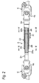
Fig. 2 is a sectional view of main parts of the intermediate shaft. -
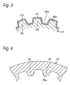
Fig. 3 is a sectional view taken along line III-III inFig. 2 . -
Fig. 4 is a sectional view taken along line IV-IV inFig. 2 . -
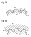
Figs. 5A and 5B are views showing steps in an example of a manufacturing method of the present invention.Fig. 5A is a sectional view showing a state in which a resin coating layer is formed in a coating step, andFig. 5B is a sectional view showing a state in which broaching is performed on the resin coating layer in a broaching step. -
Fig. 6 is a graph showing an example of a change in the temperature (°C) of the resin coating layer formed in the coating step, due to time elapse from a temperature measured immediately after the coating. -
Fig. 7 is a graph showing an example of a relationship between the elastic modulus (MPa) of the base resin and a broaching load (N) of the resin coating layer. -
Fig. 8 is a micrograph of a cross-sectional surface of the resin coating layer formed in Comparative Example. -
Fig. 9 is a micrograph of a cross-sectional surface of the resin coating layer formed in Example. -
Fig. 1 is a view schematically showing an example of an electric power steering apparatus including an intermediate shaft which is assembled as a telescopic shaft. - With reference to
Fig. 1 , an electric power steering apparatus 1 includes a steering shaft 3 that is connected to a steering wheel 2 so as to be integrally rotatable along with the steering wheel, anintermediate shaft 5 connected to the steering shaft 3 through auniversal joint 4, apinion shaft 7 connected to theintermediate shaft 5 through auniversal joint 6, and arack bar 8, as a steering shaft, which hasrack teeth 8a which mesh withpinion teeth 7a provided on thepinion shaft 7, and which extends in a rightward-leftward direction of an automobile. - A steering mechanism 9 formed by a rack and pinion mechanism is configured to include the
pinion shaft 7 and therack bar 8. - The
rack bar 8 is supported in arack housing 10 fixed to a vehicle body, in a straightly reciprocating manner through a plurality of bearings (not shown). Both ends of therack bar 8 project toward both sides of therack housing 10 andtie rods 11 are connected to the ends, respectively. - Each
tie rod 11 is connected to acorresponding steering tire 12 through a knuckle arm (not shown). - When the steering shaft 3 is rotated by an operation of the steering wheel 2, the
pinion teeth 7a and therack teeth 8a convert the rotation thereof into a linear movement of therack bar 8 in the rightward-leftward direction of the automobile such that steering of thesteering tire 12 is achieved. - The steering shaft 3 is divided into an
input shaft 3a connected to the steering wheel 2, and anoutput shaft 3b connected to thepinion shaft 7, and bothshafts torsion bar 13 in a relatively rotatable manner from each other. - In addition, the
torsion bar 13 is provided with atorque sensor 14 for detecting steering torque obtained by relative rotational displacement between bothshafts torque sensor 14 are transmitted to an electronic control unit (ECU) 15. - The
ECU 15 controls driving of a steering assistingelectric motor 17 through adriver circuit 16 in response to the torque detection results, vehicle speed detection results transmitted from a vehicle speed sensor (not shown), or the like. Output rotation speed of theelectric motor 17 is reduced through aspeed reducer 18, is transmitted to thepinion shaft 7, and is converted into a straight movement of therack bar 8 such that the steering is assisted. - The
speed reducer 18 includes apinion 19, as an input shaft, which is rotated and driven by theelectric motor 17, and amain wheel 20 that is meshed with thepinion 19 and that is connected to be integrally rotatable along with theoutput shaft 3b of the steering shaft 3. -
Fig. 2 is a sectional view of main parts of the intermediate shaft. - With reference to
Figs. 1 and2 , theintermediate shaft 5 includes amale shaft 21, for example, as a lower shaft, and a cylindricalfemale shaft 22, for example, as an upper shaft. - An upper end of the
female shaft 22 is connected to ayoke 4a of theuniversal joint 4, and a lower end of themale shaft 21 is connected to a yoke 6a of theuniversal joint 6. - The
female shaft 22 has afirst end 23 as an open end, and asecond end 24 as a closed end. Thesecond end 24 is connected to the end of theyoke 4a of theuniversal joint 4 and is closed. - The
male shaft 21 is inserted into thefemale shaft 22 from thefirst end 23 side, and is connected to be slidable in the axial direction X1. Specifically, themale shaft 21 and thefemale shaft 22 are connected by spline fitting. -
Fig. 3 is a sectional view taken along line III-III inFig. 2 . In addition,Fig. 4 is a sectional view taken along line IV-IV inFig. 2 . - With reference to
Figs. 2 and3 , an outercircumferential surface 21 a of themale shaft 21 hasmale splines 25 parallel to the axial direction X1. With reference toFigs. 2 and4 , an innercircumferential surface 22a of thefemale shaft 22 hasfemale splines 26 that are parallel to the axial direction X1 and meshed with the male splines 25. - The meshing, that is, the spline fitting, of the male splines 25 and the
female splines 26 enables themale shaft 21 and thefemale shaft 22 to relatively slide in the axial direction X1 and to integrally rotate. - With reference to
Fig. 3 , the outercircumferential surface 21 a of themale shaft 21 havingmale splines 25 is coated with aresin coating layer 27. - Such a
resin coating layer 27 is provided, thereby applying predetermined sliding resistance between themale shaft 21 and thefemale shaft 22 and a clearance between bothshafts - The
intermediate shaft 5, as the telescopic shaft, in which themale shaft 21 has the outercircumferential surface 21a havingmale splines 25 which is coated with theresin coating layer 27, can be manufactured by the manufacturing method of the present invention through the coating step, a broaching step, and a cooling step, described above. -
Figs. 5A and 5B are views showing steps in an example of the manufacturing method of the present invention.Fig. 5A is a sectional view showing a state in which the resin coating layer is formed in the coating step, andFig. 5B is a sectional view showing a state in which broaching is performed in the broaching step. - First, in the coating step, the powder coating material as a base material of the
resin coating layer 27 enters a state of being suspended or fluidized in a fluid bath by blowing air or the like therein. Subsequently, themale shaft 21 heated to a temperature equal to or above the melting point of the base resin contained in the powder coating material is dipped into the suspended and fluidized powder coating material. - In this manner, the powder coating material is attached to the outer
circumferential surface 21 a of themale shaft 21, and is melted and spread such that theresin coating layer 27 is formed (refer toFig. 5A ). - In this stage, it is preferable that, as shown in
Fig. 5A , the powder coating material forms a thick layer such that theresin coating layer 27 is formed to be as continuous as possible. In this manner, for example, polyamide 610 or the like has high viscosity when melting, and has low throwing power after the attachment. Therefore, even in a case where a powder coating material containing a base resin which is not smoothly spread by melting, the continuousresin coating layer 27 can be formed on the outercircumferential surface 21 a. - As the base resin, in addition to polyamide 610 described above, various types of thermoplastic resins can be used as a powder coating material for powder coating, such as engineering plastic or super engineering plastics, such as polyamide 612, polyphenylene sulfide (PPS), polyether ether ketone (PEEK), amorphous polyarylate (PAR), polysulfone (PSF), polyether sulfone (PES), polyimide, polyetherimide (PEI), liquid crystal polymer (LCD), or fluorine resin.
- Particularly, as described above, it is preferable that polyamide 610 is used as the base resin, in regard of obtaining the
resin coating layer 27 having high heat resistance so as to endure, for example, the use in an engine room. - There is no particular limitation on thickness of the
resin coating layer 27 in the coating step; however, it is preferable that a thickness t of atooth groove 25a between themale splines 25 is equal to or greater than 100 µm, and preferably equal to or smaller than 1.5 mm. - The
resin coating layer 27 formed in the coating step before performing the broaching has the thickness t less than the range, and particularly, polyamide 610 or the like has the high viscosity when melting and has low throwing power after the attachment. Therefore, when the powder coating material containing the base resin, which is not smoothly spread by melting, is used, there is a concern that it is not possible to form theresin coating layer 27 continuously from the inside of thetooth groove 25a to atooth tip 25b of the male splines 25. - In addition, there is a concern that the rattling is likely to occur due to the elastic modulus of the
resin coating layer 27 by cooling, and the clearance set between themale shaft 21 and thefemale shaft 22; however, the rattling occurs when the resin coating layer formed through the broaching step to the cooling step has too small a thickness or when it is not possible to sufficiently fill the clearance described above. - In comparison, in a case where the thickness t exceeds the range, there is a concern that a difference in temperature in a thickness direction will become significant in the thick
resin coating layer 27 before performing broaching, particularly, in theresin coating layer 27 in thetooth groove 25a, and vacuum voids will be formed. - In contrast, the thickness t is within the range described above and thereby, it is possible to have a thickness appropriate to fill the clearance set between the
male shaft 21 and thefemale shaft 22 and it is possible to further efficiently form theresin coating layer 27 continuous from the inside of thetooth groove 25a to thetooth tip 25b of themale spline 25 without a vacuum void. - Next, in the broaching step, the
resin coating layer 27 is caused to be thin by the broaching before the cooling of the formedresin coating layer 27 is completed. - Specifically, for example, with reference to
Fig. 5B , themale shaft 21, on which theresin coating layer 27 formed in the previous coating step is not completely cooled, and is caused to pass through abroach 28 prepared in advance, thereby causing theresin coating layer 27 to be subjected to the broaching and to become thin. - The
broach 28 has an cylindrical innercircumferential surface 28a with a plurality ofteeth 29 that have a cross-sectional shape similar to thefemale splines 26 of thefemale shaft 22 and are parallel and meshed with thetooth groove 25a between themale splines 25 of themale shaft 21, and theteeth 29 are formed to have a cross-sectional shape and a dimension with a clearance separated between themale splines 25 by the thickness of theresin coating layer 27 after the broaching and before the cooling. - In a state in which the central axis of the
male shaft 21 is coincident with that of thebroach 28, and thetooth groove 25a of themale shaft 21 is coincident with thetooth 29 of thebroach 28, in phase, themale shaft 21 is caused to pass through thebroach 28, and thereby, theresin coating layer 27 is subjected to the broaching and becomes thin. - According to the present invention, in a state in which the resin coating layer formed in the coating step before completing the cooling, has sufficiently decreased thickness through the broaching step, it is possible to perform the cooling in the following cooling step. Therefore, it is possible to significantly reduce the temperature difference in the thickness direction in the
resin coating layer 27 in the cooling step and it is possible to reduce vacuum voids, compared to the related art in which cooling is performed on the original thickness without being reduced and the broaching is performed after the cooling is completed. - In addition, since the
resin coating layer 27 becomes thin in the broaching step, and then is cooled, it is advantageous that, in such aresin coating layer 27, a period of time of cooling themale shaft 21 coated with theresin coating layer 27 is shortened, compared to the related art, and it is possible to enhance productivity of theintermediate shaft 5 as the telescopic shaft. - A timing of performing the broaching may be appropriate as long as the broaching is performed before the cooling of the
resin coating layer 27 formed in the coating step described above is completed. However, it is preferable that theresin coating layer 27 is subjected to the broaching at a temperature which is equal to or higher than a temperature below the melting point by 30°C and is equal to or lower than the melting point of the base resin contained in the powder coating material. - For example, in a case where polyamide 610 having the melting point of 220°C is used as the base resin, it is preferable that the broaching is performed within a range from 190°C to 220°C.
-
Fig. 6 is a graph showing an example of a change in the temperature (°C) of the resin coating layer formed in the coating step, due to time elapse from a temperature measured immediately after the coating.Fig. 7 is a graph showing an example of a relationship between the elastic modulus (MPa) of the base resin and a broaching load (N) of the resin coating layer. - With reference to
Fig. 6 , the temperature of theresin coating layer 27 formed on the outercircumferential surface 21 a of themale shaft 21 in the coating step, is gradually lowered after a time point (time point at 0 minutes inFig. 6 ) at which themale shaft 21 is pulled out from the fluid bath. - However, the temperature of the heated
male shaft 21 is unlikely to be lowered as described above. Therefore, although the broaching is performed after the temperature is lowered to a temperature lower than the temperature below the melting point of the base resin by 30°C, there is a concern that the temperature difference in the thickness direction in theresin coating layer 27 having the thickness obtained before performing the broaching will become significant until then and vacuum voids will be formed. - In addition, with reference to
Fig. 7 , the lower the temperature of the base resin, the more the elastic modulus (MPa) is increased, and a broaching load (N) of theresin coating layer 27 tends to be increased proportional thereto. - Therefore, in the case where the broaching is performed after the temperature is lowered to a temperature lower than the temperature below the melting point of the base resin by 30°C, the broaching load (N) is significantly increased, and there is a concern that workability of the broaching will be lowered or the hardened
resin coating layer 27 will be easily peeled off from themale shaft 21 due to an excessive load. - In comparison, since the
resin coating layer 27 does not start to be solidified at a temperature exceeding the melting point, there is a concern that it is not possible to perform the broaching. - It is preferable that the broaching is performed after the
resin coating layer 27 starts to be solidified to a certain extent, because the workability of the broaching is enhanced. Therefore, it is preferable that the broaching is performed at a temperature below the melting point of the base resin, at a temperature below the melting point by 5°C, and particularly, at a temperature below the melting point by 10°C. - In the following cooling step, the thin
resin coating layer 27 is cooled to room temperature for eachmale shaft 21, and then the male shaft is combined with thefemale shaft 22, thereby enabling theintermediate shaft 5 to be manufactured as the telescopic shaft, shown inFigs. 1 and2 . - The
resin coating layer 27 may not be formed on the outercircumferential surface 21 a of themale shaft 21, and may be formed on the innercircumferential surface 22a of thefemale shaft 22. Here, there is no need to form the coating layer on both surface sides. - The steering apparatus including the telescopic shaft assembled as the
intermediate shaft 5 is not limited to the column-type electric power steering apparatus shown inFig. 1 , and may be another type of power steering apparatus or a common steering apparatus without a steering assistance function. - The telescopic shaft may be applied to a shaft or the like which can be telescopic so as to secure shock absorbing stroke in the steering apparatus.
- Besides, it is possible to perform various types of design modifications within a range without departing from the gist of the present invention.
- Hereinafter, the present invention is further described based on Examples and Comparative Examples; however, configurations of the present invention are not limited to the Examples and Comparative Examples.
- The
resin coating layer 27 was formed on the outercircumferential surface 21 a including the male splines 25 of themale shaft 21 shown inFigs. 1 to 4 , using the powder coating material containing polyamide 610 (the melting point of 220°C) as the base resin, by the powder-fluidized bed dip method (Fig. 5A ). - Conditions were as follows. The temperature of the
male shaft 21 was 250°C and the thickness t of theresin coating layer 27 in thetooth groove 25a between themale splines 25 was 1 mm. - When the temperature was in a range of 190°C to 220°C before the cooling of the
resin coating layer 27 was completed, the broaching was performed using thebroach 28, and theresin coating layer 27 became thin so as to have the thickness t of about 300 µm in thetooth groove 25a between the male splines 25 (Fig. 5B ). - The
resin coating layer 27 subjected to the broaching was cooled to room temperature for eachmale shaft 21 and themale shaft 21 was produced in which the outercircumferential surface 21a including the male splines 25 of themale shaft 21 was coated with theresin coating layer 27. - The resin coating layer obtained after the coating step was cooled to room temperature for each
male shaft 21, and then themale shaft 21 was produced in which the outercircumferential surface 21 a including the male splines 25 of themale shaft 21 was coated with theresin coating layer 27, similar to Example 1 except for the broaching. - In the
male shafts 21 produced by Example 1 and Comparative Example 1, a cross-sectional surface cut for each resin coating layer was observed under the telescope and it is verified that the vacuum void was formed in the resin coating layer as shown inFig. 8 , in Comparative Example 1. In comparison, in Example 1, no vacuum void was found in the resin coating layer as shown inFig. 9 . - According to the manufacturing of the present invention in which the broaching step is performed before the cooling of the formed resin coating layer is completed after the coating step, it is verified from the above results that it is possible to form, on the outer circumferential surface of the male shaft, a continuous resin coating layer without a vacuum void by the powder-fluidized bed dip method.
- According to the present invention, the resin coating layer formed on the attachment target surface in the coating step is subjected to the broaching in the following broaching step before the cooling thereof is completed and the thickness of the layer is sufficiently reduced, and then the cooling is performed in the cooling step. Therefore, it is possible to significantly reduce the temperature difference in the thickness direction in the resin coating layer in the cooling step and it is possible to reduce vacuum voids, compared to the related art in which cooling is performed on the original thickness without being reduced and the broaching is performed after the cooling is completed.
- Therefore, in the coating step, for example, polyamide 610 or the like has high viscosity when melting, and has low throwing power after the attachment. Therefore, even in a case where a thickness of a powder coating material containing a base resin which is not smoothly spread by melting is increased, it is possible to manufacture the telescopic shaft in which the continuous resin coating layer without a vacuum void can be formed to have a predetermined thickness on the attachment target surface through the following broaching step and the cooling step.
- In addition, since the resin coating layer becomes thin in the broaching step, and then is cooled, it is advantageous that, in such a resin coating layer, a period of time of cooling the male shaft or the female shaft coated with the resin coating layer is shortened, compared to the related art, and it is possible to enhance productivity of the intermediate shaft.
- In the broaching step of the present invention, it is preferable that the resin coating layer is subjected to the broaching at a temperature which is equal to or higher than the temperature below the melting point by 30°C and is equal to or less than the melting point of the base resin contained in the powder coating material.
- As described above, the temperature of the heated male shaft is unlikely to be lowered as described above. Therefore, although the broaching is performed after the temperature is lowered to a temperature lower than the temperature below the melting point of the base resin by 30°C, there is a concern that the temperature difference in the thickness direction in the resin coating layer having the thickness obtained before performing the broaching will become significant until then and vacuum voids will be formed.
- In addition, the lower the temperature, the more the elastic modulus of the base resin is increased, and a broaching load in the broaching tends to be increased proportional thereto.
- Therefore, in the case where the broaching is performed after the temperature is lowered to a temperature lower than the temperature below the melting point of the base resin by 30°C, the broaching load is significantly increased, and there is a concern that workability of the broaching will be lowered or the hardened resin coating layer will be easily peeled off from the male shaft due to an excessive load.
- In comparison, since the resin coating layer does not start to be solidified at a temperature exceeding the melting point, there is a concern that it is not possible to perform the broaching.
- In the coating step of the present invention, it is preferable that the resin coating layer is formed to have the thickness of 100 µm to 1.5 mm.
- The resin coating layer formed in the coating step before performing the broaching has a thickness of less than 100 µm, and particularly, polyamide 610 or the like has the high viscosity when melting and has low throwing power after the attachment. Therefore, when the powder coating material containing the base resin, which is not smoothly spread by melting, is used, there is a concern that it is not possible to form the continuous resin coating layer continuous.
- In addition, there is a concern that the rattling is likely to occur due to the elastic modulus of the resin coating layer by cooling, or the clearance set between the male shaft and the female shaft; however, the rattling occurs when the resin coating layer formed through the broaching step to the cooling step has too small a thickness and thus, it is not possible to sufficiently fill the clearance described above.
- In comparison, in the case where the thickness exceeds 1.5 mm, there is a concern that the difference in temperature in the thickness direction will become significant in the thick resin coating layer before performing broaching and vacuum voids will be formed.
- According to the present invention, it is possible to manufacture a telescopic shaft having a continuous resin coating layer without a vacuum void, which is formed on an outer circumferential surface of a male shaft or an inner circumferential surface of a female shaft, by a powder-fluidized bed dip method using a powder coating material.
-
- 1:
- electric power steering apparatus
- 2:
- steering wheel
- 3:
- steering shaft
- 3a:
- input shaft
- 3b:
- output shaft
- 4:
- universal joint
- 4a:
- yoke
- 5:
- intermediate shaft
- 6:
- universal joint
- 6a:
- yoke
- 7:
- pinion shaft
- 7a:
- pinion teeth
- 8:
- rack bar
- 8a:
- rack teeth
- 9:
- steering mechanism
- 10:
- rack housing
- 11:
- tie rod
- 12:
- steering tire
- 13:
- torsion bar
- 14:
- torque sensor
- 15:
- ECU
- 16:
- driver circuit
- 17:
- electric motor
- 18:
- speed reducer
- 19:
- pinion
- 20:
- main wheel
- 21:
- male shaft
- 21a:
- outer circumferential surface
- 22:
- female shaft
- 22a:
- inner circumferential surface
- 23:
- first end section
- 24:
- second end section
- 25:
- male splines
- 25a:
- tooth groove
- 25b:
- tooth tip
- 26:
- female splines
- 27:
- resin coating layer
- 28:
- broach
- 28a:
- inner circumferential surface
- 29:
- teeth
- X1:
- axial direction
Claims (3)
- A method for manufacturing a telescopic shaft including a male shaft and a cylindrical female shaft slidably connected to each other in an axial direction thereof, , in which an outer circumferential surface of the male shaft or an inner circumferential surface of the female shaft is coated with a resin coating layer, the method comprising:a coating step of attaching, by a fluid bed dip method, a powder coating material on the outer circumferential surface of the male shaft which is heated in advance or on the inner circumferential surface of the female shaft which is heated in advance, and of forming the resin coating layer;a broaching step of making the resin coating layer thin by broaching before cooling of the formed resin coating layer is completed; anda cooling step of cooling the thin resin coating layer.
- The method for manufacturing the telescopic shaft according to Claim 1, wherein
in the broaching step, the resin coating layer is subjected to the broaching in a temperature which is equal to or higher than a temperature below a melting point of the base resin contained in the powder coating material by 30°C and is equal to or lower than the melting point. - The method for manufacturing the telescopic shaft according to Claim 1, wherein
in the coating step, the resin coating layer is formed to have a thickness of 100 µm to 1.5 mm.
Applications Claiming Priority (2)
| Application Number | Priority Date | Filing Date | Title |
|---|---|---|---|
| JP2013233143A JP6191869B2 (en) | 2013-11-11 | 2013-11-11 | Telescopic shaft manufacturing method |
| PCT/JP2014/079674 WO2015068831A1 (en) | 2013-11-11 | 2014-11-10 | Method for manufacturing telescopic shaft |
Publications (3)
| Publication Number | Publication Date |
|---|---|
| EP3070357A1 true EP3070357A1 (en) | 2016-09-21 |
| EP3070357A4 EP3070357A4 (en) | 2017-07-05 |
| EP3070357B1 EP3070357B1 (en) | 2018-05-16 |
Family
ID=53041604
Family Applications (1)
| Application Number | Title | Priority Date | Filing Date |
|---|---|---|---|
| EP14860825.0A Not-in-force EP3070357B1 (en) | 2013-11-11 | 2014-11-10 | Method for manufacturing telescopic shaft |
Country Status (5)
| Country | Link |
|---|---|
| US (1) | US10550285B2 (en) |
| EP (1) | EP3070357B1 (en) |
| JP (1) | JP6191869B2 (en) |
| CN (1) | CN105705811B (en) |
| WO (1) | WO2015068831A1 (en) |
Families Citing this family (2)
| Publication number | Priority date | Publication date | Assignee | Title |
|---|---|---|---|---|
| US9956985B2 (en) * | 2016-02-16 | 2018-05-01 | Steering Solutions Ip Holding Corporation | Steering shaft assembly |
| US10882070B2 (en) * | 2017-03-28 | 2021-01-05 | Steering Solutions Ip Holding Corporation | Method of manufacturing a steering shaft assembly |
Family Cites Families (14)
| Publication number | Priority date | Publication date | Assignee | Title |
|---|---|---|---|---|
| JP2884320B2 (en) * | 1994-06-10 | 1999-04-19 | 三菱電線工業株式会社 | Actuator manufacturing method, manufacturing apparatus, and structure having the actuator |
| JP2000108223A (en) * | 1998-10-01 | 2000-04-18 | Sumitomo Electric Ind Ltd | Manufacturing method of rubber coated roller |
| JP3974909B2 (en) * | 1999-09-13 | 2007-09-12 | 株式会社ジェイテクト | Manufacturing method of painted product and painted product |
| JP3631084B2 (en) | 1999-09-13 | 2005-03-23 | 光洋精工株式会社 | Coated product, method for producing the same, and coating apparatus |
| US7595095B2 (en) | 2000-09-12 | 2009-09-29 | Koyo Seiko Co. | Coated article, manufacturing method therefor and coating apparatus |
| JP3851101B2 (en) * | 2001-03-08 | 2006-11-29 | 株式会社ジェイテクト | Spline processing method |
| JP4893902B2 (en) * | 2001-03-21 | 2012-03-07 | 株式会社一宮電機 | Ring jig holding jig, set jig and punching jig, and electrostatic powder coating method using them |
| JP2003155135A (en) * | 2001-11-16 | 2003-05-27 | Inoac Corp | Method for manufacturing paper carrier roller |
| JP4566909B2 (en) | 2003-03-11 | 2010-10-20 | 日本精工株式会社 | Grease composition for resin lubrication and electric power steering device |
| JP5104001B2 (en) | 2006-12-14 | 2012-12-19 | 日本精工株式会社 | Telescopic shaft for vehicle steering |
| JP2011038560A (en) * | 2009-08-07 | 2011-02-24 | Jtekt Corp | Spline telescopic shaft, method of manufacturing the same, and vehicle steering apparatus |
| JP5240288B2 (en) * | 2009-12-25 | 2013-07-17 | 日本精工株式会社 | Spline processing method |
| JP5419747B2 (en) * | 2010-02-23 | 2014-02-19 | 株式会社ジェイテクト | Spline telescopic shaft manufacturing method, spline telescopic shaft and vehicle steering telescopic shaft |
| JP5867773B2 (en) | 2011-03-18 | 2016-02-24 | 株式会社ジェイテクト | Manufacturing method of power transmission shaft |
-
2013
- 2013-11-11 JP JP2013233143A patent/JP6191869B2/en not_active Expired - Fee Related
-
2014
- 2014-11-10 EP EP14860825.0A patent/EP3070357B1/en not_active Not-in-force
- 2014-11-10 US US15/032,468 patent/US10550285B2/en not_active Expired - Fee Related
- 2014-11-10 WO PCT/JP2014/079674 patent/WO2015068831A1/en not_active Ceased
- 2014-11-10 CN CN201480061549.XA patent/CN105705811B/en not_active Expired - Fee Related
Also Published As
| Publication number | Publication date |
|---|---|
| WO2015068831A1 (en) | 2015-05-14 |
| EP3070357B1 (en) | 2018-05-16 |
| CN105705811B (en) | 2019-04-16 |
| CN105705811A (en) | 2016-06-22 |
| JP2015094404A (en) | 2015-05-18 |
| US20160257850A1 (en) | 2016-09-08 |
| EP3070357A4 (en) | 2017-07-05 |
| US10550285B2 (en) | 2020-02-04 |
| JP6191869B2 (en) | 2017-09-06 |
Similar Documents
| Publication | Publication Date | Title |
|---|---|---|
| JP5104332B2 (en) | Telescopic shaft manufacturing method and telescopic shaft manufactured by this manufacturing method | |
| CN102666251B (en) | Telescopic shaft | |
| US10830282B2 (en) | Sliding shaft and steering device | |
| US9446782B2 (en) | Telescopic shaft and manufacturing method thereof | |
| US9701334B2 (en) | Vehicle steering device | |
| EP3070357B1 (en) | Method for manufacturing telescopic shaft | |
| EP2998190B1 (en) | Intermediate shaft | |
| JP6132154B2 (en) | Sliding shaft and steering device | |
| JP2010127295A (en) | Manufacturing method for telescopic shaft, and telescopic shaft manufactured by this manufacturing method | |
| JP6489362B2 (en) | Manufacturing method of sliding shaft | |
| JP7534151B2 (en) | Shaft and method for manufacturing the same | |
| JP7484565B2 (en) | Shaft and method for manufacturing the same | |
| JP5510602B2 (en) | Telescopic shaft manufacturing method and telescopic shaft manufactured by this manufacturing method | |
| WO2016084758A1 (en) | Intermediate shaft and method for manufacturing same | |
| CN103282682B (en) | Telescopic shaft | |
| CN103282682A (en) | Telescopic shaft |
Legal Events
| Date | Code | Title | Description |
|---|---|---|---|
| PUAI | Public reference made under article 153(3) epc to a published international application that has entered the european phase |
Free format text: ORIGINAL CODE: 0009012 |
|
| 17P | Request for examination filed |
Effective date: 20160506 |
|
| AK | Designated contracting states |
Kind code of ref document: A1 Designated state(s): AL AT BE BG CH CY CZ DE DK EE ES FI FR GB GR HR HU IE IS IT LI LT LU LV MC MK MT NL NO PL PT RO RS SE SI SK SM TR |
|
| AX | Request for extension of the european patent |
Extension state: BA ME |
|
| DAX | Request for extension of the european patent (deleted) | ||
| RIN1 | Information on inventor provided before grant (corrected) |
Inventor name: NISHIDA, TOMOYA |
|
| A4 | Supplementary search report drawn up and despatched |
Effective date: 20170607 |
|
| RIC1 | Information provided on ipc code assigned before grant |
Ipc: F16D 3/06 20060101AFI20170531BHEP Ipc: B62D 1/20 20060101ALI20170531BHEP Ipc: C09D 201/00 20060101ALI20170531BHEP Ipc: C09D 5/03 20060101ALI20170531BHEP |
|
| GRAP | Despatch of communication of intention to grant a patent |
Free format text: ORIGINAL CODE: EPIDOSNIGR1 |
|
| STAA | Information on the status of an ep patent application or granted ep patent |
Free format text: STATUS: GRANT OF PATENT IS INTENDED |
|
| INTG | Intention to grant announced |
Effective date: 20171201 |
|
| GRAS | Grant fee paid |
Free format text: ORIGINAL CODE: EPIDOSNIGR3 |
|
| GRAA | (expected) grant |
Free format text: ORIGINAL CODE: 0009210 |
|
| STAA | Information on the status of an ep patent application or granted ep patent |
Free format text: STATUS: THE PATENT HAS BEEN GRANTED |
|
| AK | Designated contracting states |
Kind code of ref document: B1 Designated state(s): AL AT BE BG CH CY CZ DE DK EE ES FI FR GB GR HR HU IE IS IT LI LT LU LV MC MK MT NL NO PL PT RO RS SE SI SK SM TR |
|
| REG | Reference to a national code |
Ref country code: GB Ref legal event code: FG4D |
|
| REG | Reference to a national code |
Ref country code: CH Ref legal event code: EP |
|
| REG | Reference to a national code |
Ref country code: IE Ref legal event code: FG4D |
|
| REG | Reference to a national code |
Ref country code: DE Ref legal event code: R096 Ref document number: 602014025717 Country of ref document: DE |
|
| REG | Reference to a national code |
Ref country code: AT Ref legal event code: REF Ref document number: 999867 Country of ref document: AT Kind code of ref document: T Effective date: 20180615 |
|
| REG | Reference to a national code |
Ref country code: NL Ref legal event code: MP Effective date: 20180516 |
|
| REG | Reference to a national code |
Ref country code: LT Ref legal event code: MG4D Ref country code: FR Ref legal event code: PLFP Year of fee payment: 5 |
|
| PG25 | Lapsed in a contracting state [announced via postgrant information from national office to epo] |
Ref country code: NO Free format text: LAPSE BECAUSE OF FAILURE TO SUBMIT A TRANSLATION OF THE DESCRIPTION OR TO PAY THE FEE WITHIN THE PRESCRIBED TIME-LIMIT Effective date: 20180816 Ref country code: SE Free format text: LAPSE BECAUSE OF FAILURE TO SUBMIT A TRANSLATION OF THE DESCRIPTION OR TO PAY THE FEE WITHIN THE PRESCRIBED TIME-LIMIT Effective date: 20180516 Ref country code: FI Free format text: LAPSE BECAUSE OF FAILURE TO SUBMIT A TRANSLATION OF THE DESCRIPTION OR TO PAY THE FEE WITHIN THE PRESCRIBED TIME-LIMIT Effective date: 20180516 Ref country code: BG Free format text: LAPSE BECAUSE OF FAILURE TO SUBMIT A TRANSLATION OF THE DESCRIPTION OR TO PAY THE FEE WITHIN THE PRESCRIBED TIME-LIMIT Effective date: 20180816 Ref country code: ES Free format text: LAPSE BECAUSE OF FAILURE TO SUBMIT A TRANSLATION OF THE DESCRIPTION OR TO PAY THE FEE WITHIN THE PRESCRIBED TIME-LIMIT Effective date: 20180516 Ref country code: LT Free format text: LAPSE BECAUSE OF FAILURE TO SUBMIT A TRANSLATION OF THE DESCRIPTION OR TO PAY THE FEE WITHIN THE PRESCRIBED TIME-LIMIT Effective date: 20180516 |
|
| PG25 | Lapsed in a contracting state [announced via postgrant information from national office to epo] |
Ref country code: LV Free format text: LAPSE BECAUSE OF FAILURE TO SUBMIT A TRANSLATION OF THE DESCRIPTION OR TO PAY THE FEE WITHIN THE PRESCRIBED TIME-LIMIT Effective date: 20180516 Ref country code: NL Free format text: LAPSE BECAUSE OF FAILURE TO SUBMIT A TRANSLATION OF THE DESCRIPTION OR TO PAY THE FEE WITHIN THE PRESCRIBED TIME-LIMIT Effective date: 20180516 Ref country code: HR Free format text: LAPSE BECAUSE OF FAILURE TO SUBMIT A TRANSLATION OF THE DESCRIPTION OR TO PAY THE FEE WITHIN THE PRESCRIBED TIME-LIMIT Effective date: 20180516 Ref country code: GR Free format text: LAPSE BECAUSE OF FAILURE TO SUBMIT A TRANSLATION OF THE DESCRIPTION OR TO PAY THE FEE WITHIN THE PRESCRIBED TIME-LIMIT Effective date: 20180817 Ref country code: RS Free format text: LAPSE BECAUSE OF FAILURE TO SUBMIT A TRANSLATION OF THE DESCRIPTION OR TO PAY THE FEE WITHIN THE PRESCRIBED TIME-LIMIT Effective date: 20180516 |
|
| REG | Reference to a national code |
Ref country code: AT Ref legal event code: MK05 Ref document number: 999867 Country of ref document: AT Kind code of ref document: T Effective date: 20180516 |
|
| PG25 | Lapsed in a contracting state [announced via postgrant information from national office to epo] |
Ref country code: DK Free format text: LAPSE BECAUSE OF FAILURE TO SUBMIT A TRANSLATION OF THE DESCRIPTION OR TO PAY THE FEE WITHIN THE PRESCRIBED TIME-LIMIT Effective date: 20180516 Ref country code: AT Free format text: LAPSE BECAUSE OF FAILURE TO SUBMIT A TRANSLATION OF THE DESCRIPTION OR TO PAY THE FEE WITHIN THE PRESCRIBED TIME-LIMIT Effective date: 20180516 Ref country code: EE Free format text: LAPSE BECAUSE OF FAILURE TO SUBMIT A TRANSLATION OF THE DESCRIPTION OR TO PAY THE FEE WITHIN THE PRESCRIBED TIME-LIMIT Effective date: 20180516 Ref country code: PL Free format text: LAPSE BECAUSE OF FAILURE TO SUBMIT A TRANSLATION OF THE DESCRIPTION OR TO PAY THE FEE WITHIN THE PRESCRIBED TIME-LIMIT Effective date: 20180516 Ref country code: RO Free format text: LAPSE BECAUSE OF FAILURE TO SUBMIT A TRANSLATION OF THE DESCRIPTION OR TO PAY THE FEE WITHIN THE PRESCRIBED TIME-LIMIT Effective date: 20180516 Ref country code: CZ Free format text: LAPSE BECAUSE OF FAILURE TO SUBMIT A TRANSLATION OF THE DESCRIPTION OR TO PAY THE FEE WITHIN THE PRESCRIBED TIME-LIMIT Effective date: 20180516 Ref country code: SK Free format text: LAPSE BECAUSE OF FAILURE TO SUBMIT A TRANSLATION OF THE DESCRIPTION OR TO PAY THE FEE WITHIN THE PRESCRIBED TIME-LIMIT Effective date: 20180516 |
|
| REG | Reference to a national code |
Ref country code: DE Ref legal event code: R097 Ref document number: 602014025717 Country of ref document: DE |
|
| PG25 | Lapsed in a contracting state [announced via postgrant information from national office to epo] |
Ref country code: SM Free format text: LAPSE BECAUSE OF FAILURE TO SUBMIT A TRANSLATION OF THE DESCRIPTION OR TO PAY THE FEE WITHIN THE PRESCRIBED TIME-LIMIT Effective date: 20180516 Ref country code: IT Free format text: LAPSE BECAUSE OF FAILURE TO SUBMIT A TRANSLATION OF THE DESCRIPTION OR TO PAY THE FEE WITHIN THE PRESCRIBED TIME-LIMIT Effective date: 20180516 |
|
| PLBE | No opposition filed within time limit |
Free format text: ORIGINAL CODE: 0009261 |
|
| STAA | Information on the status of an ep patent application or granted ep patent |
Free format text: STATUS: NO OPPOSITION FILED WITHIN TIME LIMIT |
|
| 26N | No opposition filed |
Effective date: 20190219 |
|
| PG25 | Lapsed in a contracting state [announced via postgrant information from national office to epo] |
Ref country code: SI Free format text: LAPSE BECAUSE OF FAILURE TO SUBMIT A TRANSLATION OF THE DESCRIPTION OR TO PAY THE FEE WITHIN THE PRESCRIBED TIME-LIMIT Effective date: 20180516 |
|
| REG | Reference to a national code |
Ref country code: CH Ref legal event code: PL |
|
| GBPC | Gb: european patent ceased through non-payment of renewal fee |
Effective date: 20181110 |
|
| PG25 | Lapsed in a contracting state [announced via postgrant information from national office to epo] |
Ref country code: LU Free format text: LAPSE BECAUSE OF NON-PAYMENT OF DUE FEES Effective date: 20181110 Ref country code: MC Free format text: LAPSE BECAUSE OF FAILURE TO SUBMIT A TRANSLATION OF THE DESCRIPTION OR TO PAY THE FEE WITHIN THE PRESCRIBED TIME-LIMIT Effective date: 20180516 |
|
| REG | Reference to a national code |
Ref country code: BE Ref legal event code: MM Effective date: 20181130 |
|
| REG | Reference to a national code |
Ref country code: IE Ref legal event code: MM4A |
|
| PG25 | Lapsed in a contracting state [announced via postgrant information from national office to epo] |
Ref country code: LI Free format text: LAPSE BECAUSE OF NON-PAYMENT OF DUE FEES Effective date: 20181130 Ref country code: CH Free format text: LAPSE BECAUSE OF NON-PAYMENT OF DUE FEES Effective date: 20181130 |
|
| PG25 | Lapsed in a contracting state [announced via postgrant information from national office to epo] |
Ref country code: IE Free format text: LAPSE BECAUSE OF NON-PAYMENT OF DUE FEES Effective date: 20181110 |
|
| PG25 | Lapsed in a contracting state [announced via postgrant information from national office to epo] |
Ref country code: AL Free format text: LAPSE BECAUSE OF FAILURE TO SUBMIT A TRANSLATION OF THE DESCRIPTION OR TO PAY THE FEE WITHIN THE PRESCRIBED TIME-LIMIT Effective date: 20180516 Ref country code: BE Free format text: LAPSE BECAUSE OF NON-PAYMENT OF DUE FEES Effective date: 20181130 |
|
| PG25 | Lapsed in a contracting state [announced via postgrant information from national office to epo] |
Ref country code: GB Free format text: LAPSE BECAUSE OF NON-PAYMENT OF DUE FEES Effective date: 20181110 |
|
| PG25 | Lapsed in a contracting state [announced via postgrant information from national office to epo] |
Ref country code: MT Free format text: LAPSE BECAUSE OF NON-PAYMENT OF DUE FEES Effective date: 20181110 |
|
| PGFP | Annual fee paid to national office [announced via postgrant information from national office to epo] |
Ref country code: DE Payment date: 20191029 Year of fee payment: 6 |
|
| PGFP | Annual fee paid to national office [announced via postgrant information from national office to epo] |
Ref country code: FR Payment date: 20191015 Year of fee payment: 6 |
|
| PG25 | Lapsed in a contracting state [announced via postgrant information from national office to epo] |
Ref country code: TR Free format text: LAPSE BECAUSE OF FAILURE TO SUBMIT A TRANSLATION OF THE DESCRIPTION OR TO PAY THE FEE WITHIN THE PRESCRIBED TIME-LIMIT Effective date: 20180516 |
|
| PG25 | Lapsed in a contracting state [announced via postgrant information from national office to epo] |
Ref country code: PT Free format text: LAPSE BECAUSE OF FAILURE TO SUBMIT A TRANSLATION OF THE DESCRIPTION OR TO PAY THE FEE WITHIN THE PRESCRIBED TIME-LIMIT Effective date: 20180516 |
|
| PG25 | Lapsed in a contracting state [announced via postgrant information from national office to epo] |
Ref country code: CY Free format text: LAPSE BECAUSE OF FAILURE TO SUBMIT A TRANSLATION OF THE DESCRIPTION OR TO PAY THE FEE WITHIN THE PRESCRIBED TIME-LIMIT Effective date: 20180516 Ref country code: MK Free format text: LAPSE BECAUSE OF NON-PAYMENT OF DUE FEES Effective date: 20180516 Ref country code: HU Free format text: LAPSE BECAUSE OF FAILURE TO SUBMIT A TRANSLATION OF THE DESCRIPTION OR TO PAY THE FEE WITHIN THE PRESCRIBED TIME-LIMIT; INVALID AB INITIO Effective date: 20141110 |
|
| PG25 | Lapsed in a contracting state [announced via postgrant information from national office to epo] |
Ref country code: IS Free format text: LAPSE BECAUSE OF FAILURE TO SUBMIT A TRANSLATION OF THE DESCRIPTION OR TO PAY THE FEE WITHIN THE PRESCRIBED TIME-LIMIT Effective date: 20180916 |
|
| REG | Reference to a national code |
Ref country code: DE Ref legal event code: R119 Ref document number: 602014025717 Country of ref document: DE |
|
| PG25 | Lapsed in a contracting state [announced via postgrant information from national office to epo] |
Ref country code: FR Free format text: LAPSE BECAUSE OF NON-PAYMENT OF DUE FEES Effective date: 20201130 |
|
| PG25 | Lapsed in a contracting state [announced via postgrant information from national office to epo] |
Ref country code: DE Free format text: LAPSE BECAUSE OF NON-PAYMENT OF DUE FEES Effective date: 20210601 |