EP3070309A1 - Condensed water supply control device for cylinder injection type internal combustion engine - Google Patents
Condensed water supply control device for cylinder injection type internal combustion engine Download PDFInfo
- Publication number
- EP3070309A1 EP3070309A1 EP14862498.4A EP14862498A EP3070309A1 EP 3070309 A1 EP3070309 A1 EP 3070309A1 EP 14862498 A EP14862498 A EP 14862498A EP 3070309 A1 EP3070309 A1 EP 3070309A1
- Authority
- EP
- European Patent Office
- Prior art keywords
- cylinder
- condensed
- condensed water
- water
- supply
- Prior art date
- Legal status (The legal status is an assumption and is not a legal conclusion. Google has not performed a legal analysis and makes no representation as to the accuracy of the status listed.)
- Granted
Links
Images



Classifications
-
- F—MECHANICAL ENGINEERING; LIGHTING; HEATING; WEAPONS; BLASTING
- F02—COMBUSTION ENGINES; HOT-GAS OR COMBUSTION-PRODUCT ENGINE PLANTS
- F02B—INTERNAL-COMBUSTION PISTON ENGINES; COMBUSTION ENGINES IN GENERAL
- F02B47/00—Methods of operating engines involving adding non-fuel substances or anti-knock agents to combustion air, fuel, or fuel-air mixtures of engines
- F02B47/02—Methods of operating engines involving adding non-fuel substances or anti-knock agents to combustion air, fuel, or fuel-air mixtures of engines the substances being water or steam
-
- F—MECHANICAL ENGINEERING; LIGHTING; HEATING; WEAPONS; BLASTING
- F02—COMBUSTION ENGINES; HOT-GAS OR COMBUSTION-PRODUCT ENGINE PLANTS
- F02B—INTERNAL-COMBUSTION PISTON ENGINES; COMBUSTION ENGINES IN GENERAL
- F02B31/00—Modifying induction systems for imparting a rotation to the charge in the cylinder
- F02B31/08—Modifying induction systems for imparting a rotation to the charge in the cylinder having multiple air inlets
- F02B31/085—Modifying induction systems for imparting a rotation to the charge in the cylinder having multiple air inlets having two inlet valves
-
- F—MECHANICAL ENGINEERING; LIGHTING; HEATING; WEAPONS; BLASTING
- F02—COMBUSTION ENGINES; HOT-GAS OR COMBUSTION-PRODUCT ENGINE PLANTS
- F02D—CONTROLLING COMBUSTION ENGINES
- F02D19/00—Controlling engines characterised by their use of non-liquid fuels, pluralities of fuels, or non-fuel substances added to the combustible mixtures
- F02D19/12—Controlling engines characterised by their use of non-liquid fuels, pluralities of fuels, or non-fuel substances added to the combustible mixtures peculiar to engines working with non-fuel substances or with anti-knock agents, e.g. with anti-knock fuel
-
- F—MECHANICAL ENGINEERING; LIGHTING; HEATING; WEAPONS; BLASTING
- F02—COMBUSTION ENGINES; HOT-GAS OR COMBUSTION-PRODUCT ENGINE PLANTS
- F02D—CONTROLLING COMBUSTION ENGINES
- F02D35/00—Controlling engines, dependent on conditions exterior or interior to engines, not otherwise provided for
- F02D35/02—Controlling engines, dependent on conditions exterior or interior to engines, not otherwise provided for on interior conditions
- F02D35/023—Controlling engines, dependent on conditions exterior or interior to engines, not otherwise provided for on interior conditions by determining the cylinder pressure
-
- F—MECHANICAL ENGINEERING; LIGHTING; HEATING; WEAPONS; BLASTING
- F02—COMBUSTION ENGINES; HOT-GAS OR COMBUSTION-PRODUCT ENGINE PLANTS
- F02D—CONTROLLING COMBUSTION ENGINES
- F02D41/00—Electrical control of supply of combustible mixture or its constituents
- F02D41/0025—Controlling engines characterised by use of non-liquid fuels, pluralities of fuels, or non-fuel substances added to the combustible mixtures
-
- F—MECHANICAL ENGINEERING; LIGHTING; HEATING; WEAPONS; BLASTING
- F02—COMBUSTION ENGINES; HOT-GAS OR COMBUSTION-PRODUCT ENGINE PLANTS
- F02D—CONTROLLING COMBUSTION ENGINES
- F02D41/00—Electrical control of supply of combustible mixture or its constituents
- F02D41/24—Electrical control of supply of combustible mixture or its constituents characterised by the use of digital means
- F02D41/26—Electrical control of supply of combustible mixture or its constituents characterised by the use of digital means using computer, e.g. microprocessor
-
- F—MECHANICAL ENGINEERING; LIGHTING; HEATING; WEAPONS; BLASTING
- F02—COMBUSTION ENGINES; HOT-GAS OR COMBUSTION-PRODUCT ENGINE PLANTS
- F02M—SUPPLYING COMBUSTION ENGINES IN GENERAL WITH COMBUSTIBLE MIXTURES OR CONSTITUENTS THEREOF
- F02M25/00—Engine-pertinent apparatus for adding non-fuel substances or small quantities of secondary fuel to combustion-air, main fuel or fuel-air mixture
- F02M25/022—Adding fuel and water emulsion, water or steam
- F02M25/0221—Details of the water supply system, e.g. pumps or arrangement of valves
- F02M25/0222—Water recovery or storage
-
- F—MECHANICAL ENGINEERING; LIGHTING; HEATING; WEAPONS; BLASTING
- F02—COMBUSTION ENGINES; HOT-GAS OR COMBUSTION-PRODUCT ENGINE PLANTS
- F02M—SUPPLYING COMBUSTION ENGINES IN GENERAL WITH COMBUSTIBLE MIXTURES OR CONSTITUENTS THEREOF
- F02M25/00—Engine-pertinent apparatus for adding non-fuel substances or small quantities of secondary fuel to combustion-air, main fuel or fuel-air mixture
- F02M25/022—Adding fuel and water emulsion, water or steam
- F02M25/0227—Control aspects; Arrangement of sensors; Diagnostics; Actuators
-
- F—MECHANICAL ENGINEERING; LIGHTING; HEATING; WEAPONS; BLASTING
- F02—COMBUSTION ENGINES; HOT-GAS OR COMBUSTION-PRODUCT ENGINE PLANTS
- F02M—SUPPLYING COMBUSTION ENGINES IN GENERAL WITH COMBUSTIBLE MIXTURES OR CONSTITUENTS THEREOF
- F02M25/00—Engine-pertinent apparatus for adding non-fuel substances or small quantities of secondary fuel to combustion-air, main fuel or fuel-air mixture
- F02M25/022—Adding fuel and water emulsion, water or steam
- F02M25/025—Adding water
- F02M25/028—Adding water into the charge intakes
-
- F—MECHANICAL ENGINEERING; LIGHTING; HEATING; WEAPONS; BLASTING
- F02—COMBUSTION ENGINES; HOT-GAS OR COMBUSTION-PRODUCT ENGINE PLANTS
- F02M—SUPPLYING COMBUSTION ENGINES IN GENERAL WITH COMBUSTIBLE MIXTURES OR CONSTITUENTS THEREOF
- F02M25/00—Engine-pertinent apparatus for adding non-fuel substances or small quantities of secondary fuel to combustion-air, main fuel or fuel-air mixture
- F02M25/022—Adding fuel and water emulsion, water or steam
- F02M25/025—Adding water
- F02M25/03—Adding water into the cylinder or the pre-combustion chamber
-
- F—MECHANICAL ENGINEERING; LIGHTING; HEATING; WEAPONS; BLASTING
- F02—COMBUSTION ENGINES; HOT-GAS OR COMBUSTION-PRODUCT ENGINE PLANTS
- F02M—SUPPLYING COMBUSTION ENGINES IN GENERAL WITH COMBUSTIBLE MIXTURES OR CONSTITUENTS THEREOF
- F02M26/00—Engine-pertinent apparatus for adding exhaust gases to combustion-air, main fuel or fuel-air mixture, e.g. by exhaust gas recirculation [EGR] systems
- F02M26/13—Arrangement or layout of EGR passages, e.g. in relation to specific engine parts or for incorporation of accessories
- F02M26/22—Arrangement or layout of EGR passages, e.g. in relation to specific engine parts or for incorporation of accessories with coolers in the recirculation passage
-
- F—MECHANICAL ENGINEERING; LIGHTING; HEATING; WEAPONS; BLASTING
- F02—COMBUSTION ENGINES; HOT-GAS OR COMBUSTION-PRODUCT ENGINE PLANTS
- F02M—SUPPLYING COMBUSTION ENGINES IN GENERAL WITH COMBUSTIBLE MIXTURES OR CONSTITUENTS THEREOF
- F02M35/00—Combustion-air cleaners, air intakes, intake silencers, or induction systems specially adapted for, or arranged on, internal-combustion engines
- F02M35/10—Air intakes; Induction systems
- F02M35/104—Intake manifolds
- F02M35/108—Intake manifolds with primary and secondary intake passages
- F02M35/1085—Intake manifolds with primary and secondary intake passages the combustion chamber having multiple intake valves
-
- Y—GENERAL TAGGING OF NEW TECHNOLOGICAL DEVELOPMENTS; GENERAL TAGGING OF CROSS-SECTIONAL TECHNOLOGIES SPANNING OVER SEVERAL SECTIONS OF THE IPC; TECHNICAL SUBJECTS COVERED BY FORMER USPC CROSS-REFERENCE ART COLLECTIONS [XRACs] AND DIGESTS
- Y02—TECHNOLOGIES OR APPLICATIONS FOR MITIGATION OR ADAPTATION AGAINST CLIMATE CHANGE
- Y02T—CLIMATE CHANGE MITIGATION TECHNOLOGIES RELATED TO TRANSPORTATION
- Y02T10/00—Road transport of goods or passengers
- Y02T10/10—Internal combustion engine [ICE] based vehicles
- Y02T10/12—Improving ICE efficiencies
Definitions
- the present invention relates to a condensed water supply control apparatus which supplies condensed water into a cylinder of an in-cylinder injection type internal combustion engine.
- the present invention aims to provide a condensed water supply control apparatus for in-cylinder injection type internal combustion engine which is capable of consuming condensed water in a cylinder while suppressing the deterioration of exhaust emission even in a low load state of the internal combustion engine.
- a condensed-water supply control apparatus as one aspect of the present invention is a condensed-water supply control apparatus for an in-cylinder injection type internal combustion engine, the condensed-water supply control apparatus being applied to the in-cylinder injection type internal combustion engine where fuel is injected from a central area lying in a cylinder, and comprising: a storage tank which stores condensed water generated at the in-cylinder injection type internal combustion engine; a condensed water supply device which is configured to supply the condensed water stored in the storage tank into the cylinder, and also to adjust a supply amount of condensed water supplied to the central area lying in the cylinder and a supply amount of condensed water supplied to a peripheral area lying in the cylinder; and a condensed-water supply control device which is configured to control the condensed water supply device in a low load state of the in-cylinder injection type internal combustion engine, to supply condensed water into the cylinder, so that the supply amount of condensed water supplied to the peripheral area lying in the cylinder is made more than the supply amount of
- an area where the spray penetration of fuel spay is affected by supply of condensed water into the cylinder is mainly the central area lying in the cylinder, and the splay penetration of fuel spray is less affected by supply of condensed water to the peripheral area lying in the cylinder.
- the supply amount of condensed water supplied to the peripheral area lying in the cylinder is made more than the supply amount of condensed water supplied to the central area lying in the cylinder. Due to this, it is possible to supply condensed water into the cylinder while suppressing the fuel sticking on the cylinder wall by reducing impact on the spray penetration of the fuel spray. Thereby, even in a low load state, it is possible to consume condensed water in the cylinder while suppressing deterioration of exhaust emission.
- the condensed-water supply control device may be configured to control the condensed water supply device to supply the condensed water into the cylinder, in a case where a storage water quantity of the storage tank is in an excessive water state that the storage water quantity is equal to or more than a predetermined quantity. According to this embodiment, it is possible to consume condensed water, in a case where the storage water quantity of condensed water is in the excessive water state in the low load state of the internal combustion engine and the superfluous condensed water is preferably consumed.
- the condensed-water supply control device may be configured to control the condensed water supply device to supply the condensed water limitedly to the peripheral area lying in the cylinder so that the supply amount of condensed water supplied to the peripheral area lying in the cylinder is made more than the supply amount of condensed water supplied to the central area lying in the cylinder.
- the condensed-water supply control device may be configured to control the condensed water supply device to supply the condensed water limitedly to the peripheral area lying in the cylinder so that the supply amount of condensed water supplied to the peripheral area lying in the cylinder is made more than the supply amount of condensed water supplied to the central area lying in the cylinder.
- the condensed-water supply control apparatus may comprise as the condensed water supply device: a first intake port which makes intake gas flow into the central area lying in the cylinder; a second intake port which makes intake gas flow into the peripheral area lying in the cylinder; a first supply device which supplies condensed water to at least the first intake port; and a second supply device which supplies condensed water to the peripheral area of the cylinder; and a supply change device which changes a water supply amount of each of the first supply device and the second supply device.
- the in-cylinder injection type internal combustion engine may have an intake passage which divides into the first intake port and the second intake port; and the first supply device may be provided to the first intake port lying at downstream further than a position where the intake passage divides into the first intake port and the second intake port.
- the second supply device may be provided to the second intake port.
- the first supply device may be provided so as to face in a direction along the peripheral area lying in the cylinder.
- the in-cylinder injection type internal combustion engine may have an intake passage which divides into the first intake port and the second intake port; and the second supply device may be provided to the intake passage lying at upstream further than a position where the intake passage divides into the first intake port and the second intake port.
- an internal combustion engine 1 is configured as a diesel engine which is an in-cylinder injection type internal combustion engine.
- the internal combustion engine 1 has a cylinder 2, and a fuel injection valve 3 is provided at a central area 2a of the cylinder 2.
- the internal combustion engine 1 is configured as a serial four-cylinder type internal combustion engine where four cylinders 2 are aligned in one direction.
- the fuel injection valve 3 injects fuel radially from the central area 2a of the cylinder 2.
- the cylinder 2 is provided with two kinds of intake ports 5 and 6. Intake gas is led into the cylinder 2 via these intake ports 5 and 6.
- a first intake port 5 is configured as a well-known helical intake port.
- the first intake port 5 makes an intake gas flow into the central area 2a of the cylinder 2 as a swirling flow F2 by adding rotation to an intake flow F1.
- a second intake port 6 is configured as a well-known tangential intake port. The second intake port 6 leads intake gas flow so that the intake gas flows along an inner circumference of the cylinder 2 to make the intake gas flow into a peripheral area 2b of the cylinder 2.
- the intake gas After being led via the intake ports 5 and 6 into and filled in the cylinder 2, the intake gas is compressed in a compression stroke.
- the fuel When fuel is injected from the fuel injection valve 3 at a late stage of the compression stroke, the fuel self-ignites and burns while involving the intake gas in the cylinder 2.
- exhaust gas After burning, exhaust gas is led to an exhaust system not illustrated, purified by an exhaust gas purifying device such as an exhaust gas purification catalyst and a filter, and then, the exhaust gas is discharged to atmospheric air.
- an exhaust gas purifying device such as an exhaust gas purification catalyst and a filter
- the internal combustion engine 1 is provided with a well-known EGR device 10 which recirculates a part of the exhaust gas to an intake system, for reduction of NOx and improvement of fuel efficiency.
- the EGR device 10 includes an EGR cooler 11 which cools EGR gas taken out from the exhaust system.
- the EGR cooler 11 uses cooling water of the internal combustion engine 1 as refrigerant, and makes the refrigerant and the warm exhaust gas exchange heat therebetween to lower the temperature of the EGR gas. By lowering the temperature of the EGR gas, moisture included in the EGR gas is condensed. Due to this, condensed water is generated in the EGR cooler 11.
- the internal combustion engine 1 is provided with a condensed water processing device 20.
- the condensed water processing device 20 comprises a storage tank 21 which stores condensed water CW; and a condensed water supply mechanism 22 as a condensed water supply device which supplies the condensed water CW stored in the storage tank 21 to the intake system of the internal combustion engine 1.
- the storage tank 21 is provided with a water level sensor 24 which outputs a signal according to the storage water quantity (the water level) of the condensed water CW stored in the storage tank 21.
- the condensed water supply mechanism 22 has a supply passage 25 connecting the storage tank 21 and each of the intake ports 5 and 6.
- the supply passage 25 divides at its downstream side into a first branched passage 25a which is connected with the first intake port 5 and a second branched passage 25b which is connected with the second intake port 6.
- adding water valves 26 and 27 are provided so that the tips of the adding water valves 26 and 27 are exposed inside the intake ports 5 and 6 respectively.
- the supply passage 25 is provided with a supply pump 28. It is possible to change the supply amount of water supplied to each of the first and second intake ports 5 and 6 by opening and closing each of the adding water valves 26 and 27 and adjusting a valve opening period for each of them.
- Each of the adding water valves 26 and 27 corresponds to a supply change device.
- the first branched passage 25a which supplies condensed water to the first intake port 5 corresponds to a first supply device.
- the second branched passage 25b which supplies condensed water to the second intake port 6 corresponds to a second supply device.
- the first intake port 5 makes intake gas flow into the central area 2a lying in the cylinder 2. Accordingly, by supplying condensed water to the first intake port 5 via the first branched passage 25a, it is possible to supply the condensed water limitedly to the central area 2a lying in the cylinder 2. In addition, by supplying condensed water to both of the intake ports 5 and 6 via the two branched passages 25a and 25b, it is possible to supply condensed water to a whole of the inside of the cylinder 2. Further, by supplying condensed water to the second intake port 6 via the second branched passage 25b, it is possible to supply condensed water limitedly to the peripheral area 2b lying in the cylinder 2. Thereby, it is possible to make the supply amount of condensed water supplied to the periphery area 2b lying in the cylinder 2 more than the supply amount of condensed water supplied to the central area 2a lying in the cylinder 2.
- the gas density of an area where the condensed water has been supplied decreases. Therefore, it is suppressed to decrease the spray penetration of fuel spray injected from the fuel injection valve 3, and as a result the fuel could easily stick on the wall surface of the cylinder 2.
- the discharge amount of carbohydrate increases and thereby, the exhaust emission is deteriorated.
- an area where the spray penetration of the fuel spray is affected by supply of condensed water into the cylinder is mainly the central area 2a lying in the cylinder 2, and the spray penetration of the fuel spray is less affected by supply of condensed water to the peripheral area 2b lying in the cylinder 2.
- the condensed water is supplied limitedly to the peripheral area 2b lying in the cylinder 2, where the spray penetration of fuel spray is less affected.
- the supply amount of condensed water supplied to the peripheral area 2b lying in the cylinder 2 is made so as to be more than the supply amount of condensed water supplied to the central area 2a lying in the cylinder 2. Thereby, it is possible to consume the superfluous condensed water inside the cylinder 2 while suppressing the deterioration of exhaust emission.
- the internal combustion engine 1 is provided with an engine control unit (ECU) 30 configured as a computer which controls various portions of the internal combustion engine 1.
- the ECU 30 controls main operations of the fuel injection valve 3 and the like of the internal combustion engine 1.
- the ECU 30 is also used for processing of condensed water.
- signals are inputted from a lot of sensors which detect various physical amounts for obtaining the operating conditions of the internal combustion engine 1.
- a crank angle sensor 31 an accelerator opening degree sensor 32, and the like are provided to the internal combustion engine 1.
- the crank angle sensor 31 outputs a signal according to a crank angle of the internal combustion engine 1.
- the accelerator opening degree sensor 32 outputs a signal according to the depression amount (the accelerator opening degree) of an accelerator pedal 29 provided to the internal combustion engine 1.
- the output signals from these sensors are inputted to the ECU 30.
- Control relating to the above mentioned supply of condensed water is realized by the ECU 30 which executes a control routine shown in fig.2 .
- a computer program for the control routine shown in fig.2 is stored in the ECU 30.
- the computer program is read out as appropriate, and executed repeatedly at predetermined intervals.
- the ECU 30 obtains engine operating conditions of the internal combustion engine 1.
- the ECU 30 obtains the engine speed and the load of the internal combustion engine 1 as the engine operating conditions.
- the ECU 30 obtains the engine speed by referring to the output signal from the crank angle sensor 31, and obtains the load by referring to the output signal from the accelerator opening degree sensor 32.
- the ECU 30 determines whether a water supply condition has been satisfied or not.
- the water supply condition is a condition for supplying condensed water to the internal combustion engine 1.
- it is determined whether the water supply condition has been satisfied depending on whether the load of the internal combustion engine 1 obtained at step S1 falls under a high load state where the load excesses a predetermined threshold.
- the ECU 30 goes to step S3, and in a case where the water supply condition is not satisfied, the ECU 30 goes to step S7.
- the supply of condensed water is executed in a case where the load of the internal combustion engine 1 falls under the high load state, that is, the water supply condition has been satisfied.
- the ECU 30 obtains the storage water quantity Qw of the storage tank 21 by referring to the output signal from the water level sensor 24.
- the ECU 30 determines whether the storage water quantity Qw of the storage tank 21 is beyond a lower limit quantity Qlim1.
- the lower limit quantity Qlim1 is a predetermined quantity for determining whether the storage water quantity Qw of the storage tank 21 is in an insufficient water state. In a case where the storage water quantity Qw is beyond the lower limit quantity Qlim1, it is unnecessary to save condensed water stored. Therefore, the ECU 30 goes to step S5. On the other hand, in a case where the storage water quantity Qw is equal to or lower than the lower limit quantity Qlim1, the ECU determines that the storage water quantity Qw is in the insufficient water state and goes to step S6.
- the ECU 30 opens each of the adding water valves 26 and 27 to supply condensed water to both of the fist intake port 5 and the second intake port 6, so that the condensed water is supplied to the whole inside of the cylinder 2.
- the ECU 30 opens the adding water valve 26 and closes the adding water valve 27 to supply condensed water only to the first intake port 5, so that the condensed water is supplied limitedly to the central area 2a lying in the cylinder 2.
- the ECU 30 ends the control routine of this turn.
- the valve opening period of the adding water valve 26 is controlled so that the supply amount of condensed water is made smaller than the supply amount of condensed water supplied to be supplied at step S5.
- the area which affects combustion because of the supply of condensed water is mainly the central area 2a lying in the cylinder 2, in a case where the water supply condition has been satisfied and also the storage water quantity Qw is in the insufficient water state, condensed water is supplied limitedly to the central area 2a lying in the cylinder 2.
- the supply mount of condensed water to the peripheral area 2b lying in the cylinder 2 reduces. Therefore, it is possible to reduce the water supply quantity without deterioration of the exhaust characteristic while ensuring the mentioned effects obtained by the supply of condensed water. Thereby, it is possible to suppress the depletion of the storage tank 21 without the deterioration of the exhaust characteristic.
- the ECU 30 obtains the storage water quantity Qw of the storage tank 21 by referring to the output signal from the water level sensor 24 at step S7. At succeeding step S8, the ECU 30 determines whether the storage water quantity Qw of the storage tank 21 is less than an upper limit quantity Qlim2.
- the upper limit quantity Qlim2 is a predetermined quantity for determining whether the storage water quantity Qw of the storage tank 21 is in an excessive water state that the storage water quantity Qw is excessive. In a case where the storage water quantity Qw is less than the upper limit quantity Qlim2, the condensed water stored in the storage tank 21 is not excessive.
- the ECU 30 ends the control routine of this turn without supplying the condensed water to the cylinder 2.
- the ECU 30 determines that the storage water quantity Qw is in the excessive water state and goes to step S9.
- the ECU 30 opens the adding water valve 27 and closes the adding water valve 26 to supply condensed water only to the second intake port 6, so that the condensed water is supplied limitedly to the peripheral area 2b lying in the cylinder 2. And then, the ECU 30 ends the control routine of this turn.
- the control routine shown in fig.2 in a case of the low load state of the internal combustion engine 1 and also the excessive water state, condensed water is supplied limitedly to the peripheral area 2b lying in the cylinder 2. Accordingly, it is possible to supply condensed water into the cylinder 2 while suppressing the fuel sticking on the wall surface of the cylinder 2 by reducing impact on the spray penetration of the fuel spray. Thereby, also in a case of the low load state of the internal combustion engine 1, it is possible to consume condensed water inside the cylinder 2 while suppressing the deterioration of exhaust emission.
- the ECU functions as a condensed-water supply control device of the present invention by executing the control routine shown in fig.2 .
- the condensed water supply mechanism 50 as a condensed water supply device provided in the second embodiment comprises a supply passage 51 for supplying condensed water of the storage tank 21 to the internal combustion engine 1.
- the supply passage 51 divides at its downstream side into a first branched passage 51a which is connected with the cylinder 2 and a second branched passage 51b which is connected with an intake passage 53 lying at the upstream side of the intake ports 5 and 6.
- an adding water valve 56 is provided in a state that the tip thereof is exposed inside the cylinder 2 and faces in a direction along the peripheral area 2b lying in the cylinder 2.
- an adding water valve 57 is provided in a state that the tip thereof is exposed inside the intake passage 53.
- the supply passage 51 is provided with a supply pump 58.
- Control of the adding water valves 56 and 57 is realized by the ECU 30 which executes a control routine shown in fig.4 .
- a computer program for the control routine shown in fig.4 is stored in the ECU 30, and read out as appropriate to be executed repeatedly at predetermined intervals.
- the ECU 30 obtains engine operating conditions of the internal combustion engine 1.
- the ECU 30 obtains, as the engine operating conditions, the engine speed and the load of the internal combustion engine 1.
- the ECU 30 obtains the engine speed by referring to the output signal from the crank angle sensor 31, and obtains the load of the internal combustion engine 1 by referring to the output signal from the accelerator opening degree sensor 32.
- the ECU 30 determines whether a water supply condition, which is a condition for supplying condensed water to the internal combustion engine 1, has been satisfied or not.
- a water supply condition which is a condition for supplying condensed water to the internal combustion engine 1
- it is determined whether the water supply condition has been satisfied depending on whether the load of the internal combustion engine 1 obtained at step S21 falls under a high load state that the load is beyond a predetermined threshold.
- the ECU 30 goes to step 23, and opens the adding water valve 57 with closing the adding water valve 56, so that the condensed water is supplied to the whole inside of the cylinder 2.
- the water supply condition is not satisfied, it means that the load of the internal combustion engine 1 falls under a low load state where the load is equal to or lower than the threshold. With that, the ECU 30 goes to step S24.
- the ECU 30 obtains the storage water quantity Qw of the storage tank 21 by referring to the output signal from the water level sensor 24.
- the ECU 30 determines whether the storage water quantity Qw of the storage tank 21 is less than an upper limit quantity Qlim or not.
- the upper limit quantity Qlim is a predetermined quantity for determining whether the storage water quantity Qw of the storage tank 21 is excessive, that is, in an excessive water state. In a case where the storage water quantity Qw is less than the upper limit quantity Qlim, the condensed water stored in the storage tank 21 is not excessive. Accordingly, it is not necessary to consume the condensed water inside the cylinder 2.
- the ECU 30 ends the control routine of this turn without supplying the condensed water into the cylinder 2.
- the ECU 30 determines the storage water quantity Qw is in the excessive water state, and goes to step S26.
- the ECU 30 opens the adding water valve 56 and also closes the adding water valve 57, so that the condensed water is supplied limitedly to the peripheral area 2b lying in the cylinder 2. And then, the ECU 30 ends the control routine of this turn.
- the control routine shown in fig.4 in a case where the internal combustion engine 1 is in the low load state and also the storage water quantity is in the excessive water state, condensed water is supplied limited to the peripheral area 2b lying in the cylinder 2. Therefore, it is possible to supply condensed water while suppressing fuel sticking on the wall surface of the cylinder 2 by reducing impact on the spray penetration of the fuel spray. Thereby, it is possible to consume condensed water in the cylinder 2 while suppressing the deterioration of exhaust emission even in the low load state of the internal combustion engine 1.
- the ECU 30 functions as a condensed-water supply control device of the present invention by executing the control routine shown in fig.4 .
- the present invention is not limited to the above embodiments and may be executed in various embodiments as long as within the subject of invention.
- condensed water is supplied limitedly to the peripheral area lying in the cylinder.
- the present invention may be also applied to such an embodiment that in a case of the low load state of the internal combustion engine and the excessive water state, condensed water is supplied to an inner circumferential area lying in the cylinder.
Landscapes
- Engineering & Computer Science (AREA)
- Chemical & Material Sciences (AREA)
- Combustion & Propulsion (AREA)
- Mechanical Engineering (AREA)
- General Engineering & Computer Science (AREA)
- Water Supply & Treatment (AREA)
- Health & Medical Sciences (AREA)
- Public Health (AREA)
- Computer Hardware Design (AREA)
- Microelectronics & Electronic Packaging (AREA)
- Output Control And Ontrol Of Special Type Engine (AREA)
Abstract
Description
- The present invention relates to a condensed water supply control apparatus which supplies condensed water into a cylinder of an in-cylinder injection type internal combustion engine.
- There is known to be a condensed water supply control apparatus applied to a diesel engine which is an in-cylinder injection type internal combustion engine, in which condensed water generated in an EGR cooler is supplied into the cylinder via an intake passage to improve the exhaust characteristic (see Patent Literature 1).
- PTL1:
JP-A- 2011-111897 - In various kinds of operating conditions, for supplying condensed water effectively, it is necessary to supply the condensed water while managing the remaining amount of suppliable condensed water. If the condensed water is led into the cylinder in whole in a low load state of the internal combustion engine, the density in the in the cylinder, that is, the density of gas filled in the cylinder decreases. Due to this, it is suppressed to decrease spray penetration of fuel spray in the cylinder. Therefore, the fuel would stick on the wall surface of the cylinder and the discharge amount of carbohydrate increases. Thereby, the exhaust emission deteriorates. In the control apparatus disclosed by the
patent literature 1, in such a situation which makes the exhaust emission deteriorate, it is difficult to consume the condensed water in the cylinder. If such a situation continues, the storage water quantity of a storage tank, where condensed water generated in the internal combustion engine is stored, could reach its limit. - With that problem, the present invention aims to provide a condensed water supply control apparatus for in-cylinder injection type internal combustion engine which is capable of consuming condensed water in a cylinder while suppressing the deterioration of exhaust emission even in a low load state of the internal combustion engine.
- A condensed-water supply control apparatus as one aspect of the present invention is a condensed-water supply control apparatus for an in-cylinder injection type internal combustion engine, the condensed-water supply control apparatus being applied to the in-cylinder injection type internal combustion engine where fuel is injected from a central area lying in a cylinder, and comprising: a storage tank which stores condensed water generated at the in-cylinder injection type internal combustion engine; a condensed water supply device which is configured to supply the condensed water stored in the storage tank into the cylinder, and also to adjust a supply amount of condensed water supplied to the central area lying in the cylinder and a supply amount of condensed water supplied to a peripheral area lying in the cylinder; and a condensed-water supply control device which is configured to control the condensed water supply device in a low load state of the in-cylinder injection type internal combustion engine, to supply condensed water into the cylinder, so that the supply amount of condensed water supplied to the peripheral area lying in the cylinder is made more than the supply amount of condensed water supplied to the central area lying in the cylinder.
- In a case where fuel is injected from the central area of the cylinder, an area where the spray penetration of fuel spay is affected by supply of condensed water into the cylinder is mainly the central area lying in the cylinder, and the splay penetration of fuel spray is less affected by supply of condensed water to the peripheral area lying in the cylinder. According to the above condensed-water supply control apparatus, the supply amount of condensed water supplied to the peripheral area lying in the cylinder is made more than the supply amount of condensed water supplied to the central area lying in the cylinder. Due to this, it is possible to supply condensed water into the cylinder while suppressing the fuel sticking on the cylinder wall by reducing impact on the spray penetration of the fuel spray. Thereby, even in a low load state, it is possible to consume condensed water in the cylinder while suppressing deterioration of exhaust emission.
- In one embodiment of the condensed-water supply control apparatus as one aspect of the present invention, the condensed-water supply control device may be configured to control the condensed water supply device to supply the condensed water into the cylinder, in a case where a storage water quantity of the storage tank is in an excessive water state that the storage water quantity is equal to or more than a predetermined quantity. According to this embodiment, it is possible to consume condensed water, in a case where the storage water quantity of condensed water is in the excessive water state in the low load state of the internal combustion engine and the superfluous condensed water is preferably consumed.
- In one embodiment of the condensed-water supply control apparatus as one aspect of the present invention, the condensed-water supply control device may be configured to control the condensed water supply device to supply the condensed water limitedly to the peripheral area lying in the cylinder so that the supply amount of condensed water supplied to the peripheral area lying in the cylinder is made more than the supply amount of condensed water supplied to the central area lying in the cylinder. According to this embodiment, by supplying condensed water limitedly to the peripheral area lying in the cylinder, it becomes possible to make the supply amount of condensed water supplied to the peripheral area lying in the cylinder more than the supply amount of condensed water supplied to the central area lying in the cylinder.
- In one embodiment of the condensed-water supply control apparatus as one aspect to the present invention, the condensed-water supply control apparatus may comprise as the condensed water supply device: a first intake port which makes intake gas flow into the central area lying in the cylinder; a second intake port which makes intake gas flow into the peripheral area lying in the cylinder; a first supply device which supplies condensed water to at least the first intake port; and a second supply device which supplies condensed water to the peripheral area of the cylinder; and a supply change device which changes a water supply amount of each of the first supply device and the second supply device.
- The following features may be applied to the above embodiment. The in-cylinder injection type internal combustion engine may have an intake passage which divides into the first intake port and the second intake port; and the first supply device may be provided to the first intake port lying at downstream further than a position where the intake passage divides into the first intake port and the second intake port. The second supply device may be provided to the second intake port. Alternatively, The first supply device may be provided so as to face in a direction along the peripheral area lying in the cylinder. the in-cylinder injection type internal combustion engine may have an intake passage which divides into the first intake port and the second intake port; and the second supply device may be provided to the intake passage lying at upstream further than a position where the intake passage divides into the first intake port and the second intake port. According to the above features, it is possible to change the supply amount of water supplied to each of the first intake port and the second intake port which are different in characteristics from each other. Thereby, it is possible to change the state of supplying water into the cylinder.
-
-
Fig.1 is a configuration diagram showing schematically an essential portion of an internal combustion engine where a condensed water supply control apparatus according to a first embodiment of the present invention is applied. -
Fig.2 is a flow chart showing one example of a control routine according to the first embodiment. -
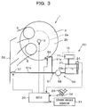
Fig.3 is a configuration diagram showing schematically an essential portion of an internal combustion engine where a condensed water supply control apparatus according to a second embodiment of the present invention is applied. -
Fig.4 is a flow chart showing one example of a control routine according to the second embodiment. - As shown in
fig.1 , aninternal combustion engine 1 is configured as a diesel engine which is an in-cylinder injection type internal combustion engine. Theinternal combustion engine 1 has acylinder 2, and afuel injection valve 3 is provided at acentral area 2a of thecylinder 2. Although only onecylinder 2 is shown inFig.1 , theinternal combustion engine 1 is configured as a serial four-cylinder type internal combustion engine where fourcylinders 2 are aligned in one direction. Thefuel injection valve 3 injects fuel radially from thecentral area 2a of thecylinder 2. Thecylinder 2 is provided with two kinds ofintake ports 5 and 6. Intake gas is led into thecylinder 2 via theseintake ports 5 and 6. Afirst intake port 5 is configured as a well-known helical intake port. As shown by an arrow infig.1 , thefirst intake port 5 makes an intake gas flow into thecentral area 2a of thecylinder 2 as a swirling flow F2 by adding rotation to an intake flow F1. On the other hand, a second intake port 6 is configured as a well-known tangential intake port. The second intake port 6 leads intake gas flow so that the intake gas flows along an inner circumference of thecylinder 2 to make the intake gas flow into aperipheral area 2b of thecylinder 2. - After being led via the
intake ports 5 and 6 into and filled in thecylinder 2, the intake gas is compressed in a compression stroke. When fuel is injected from thefuel injection valve 3 at a late stage of the compression stroke, the fuel self-ignites and burns while involving the intake gas in thecylinder 2. After burning, exhaust gas is led to an exhaust system not illustrated, purified by an exhaust gas purifying device such as an exhaust gas purification catalyst and a filter, and then, the exhaust gas is discharged to atmospheric air. - The
internal combustion engine 1 is provided with a well-knownEGR device 10 which recirculates a part of the exhaust gas to an intake system, for reduction of NOx and improvement of fuel efficiency. The EGRdevice 10 includes anEGR cooler 11 which cools EGR gas taken out from the exhaust system. As known well, the EGRcooler 11 uses cooling water of theinternal combustion engine 1 as refrigerant, and makes the refrigerant and the warm exhaust gas exchange heat therebetween to lower the temperature of the EGR gas. By lowering the temperature of the EGR gas, moisture included in the EGR gas is condensed. Due to this, condensed water is generated in the EGRcooler 11. - In order to collect and process condensed water generated in the
EGR cooler 11, theinternal combustion engine 1 is provided with a condensedwater processing device 20. The condensedwater processing device 20 comprises astorage tank 21 which stores condensed water CW; and a condensedwater supply mechanism 22 as a condensed water supply device which supplies the condensed water CW stored in thestorage tank 21 to the intake system of theinternal combustion engine 1. Thestorage tank 21 is provided with awater level sensor 24 which outputs a signal according to the storage water quantity (the water level) of the condensed water CW stored in thestorage tank 21. The condensedwater supply mechanism 22 has asupply passage 25 connecting thestorage tank 21 and each of theintake ports 5 and 6. Thesupply passage 25 divides at its downstream side into a firstbranched passage 25a which is connected with thefirst intake port 5 and a secondbranched passage 25b which is connected with the second intake port 6. At an end portion of each of thebranched passages water valves water valves intake ports 5 and 6 respectively. Further, thesupply passage 25 is provided with asupply pump 28. It is possible to change the supply amount of water supplied to each of the first andsecond intake ports 5 and 6 by opening and closing each of the addingwater valves water valves branched passage 25a which supplies condensed water to thefirst intake port 5 corresponds to a first supply device. The secondbranched passage 25b which supplies condensed water to the second intake port 6 corresponds to a second supply device. - As mentioned above, the
first intake port 5 makes intake gas flow into thecentral area 2a lying in thecylinder 2. Accordingly, by supplying condensed water to thefirst intake port 5 via the firstbranched passage 25a, it is possible to supply the condensed water limitedly to thecentral area 2a lying in thecylinder 2. In addition, by supplying condensed water to both of theintake ports 5 and 6 via the two branchedpassages cylinder 2. Further, by supplying condensed water to the second intake port 6 via the secondbranched passage 25b, it is possible to supply condensed water limitedly to theperipheral area 2b lying in thecylinder 2. Thereby, it is possible to make the supply amount of condensed water supplied to theperiphery area 2b lying in thecylinder 2 more than the supply amount of condensed water supplied to thecentral area 2a lying in thecylinder 2. - If the condensed water is supplied into the
cylinder 2, the gas density of an area where the condensed water has been supplied decreases. Therefore, it is suppressed to decrease the spray penetration of fuel spray injected from thefuel injection valve 3, and as a result the fuel could easily stick on the wall surface of thecylinder 2. Especially, in a case where the fuel sticks on the wall surface of thecylinder 2 in the low load state of theinternal combustion engine 1, the discharge amount of carbohydrate increases and thereby, the exhaust emission is deteriorated. - In a case where the fuel is injected from the
central area 2a lying in thecylinder 2, like theinternational combustion engine 1, it is known that an area where the spray penetration of the fuel spray is affected by supply of condensed water into the cylinder is mainly thecentral area 2a lying in thecylinder 2, and the spray penetration of the fuel spray is less affected by supply of condensed water to theperipheral area 2b lying in thecylinder 2. With that, in the present embodiment, in a case where the storage water quantity of condensed water is in an excessive water state and superfluous condensed water is preferably consumed in the low load state of theinternal combustion engine 1, the condensed water is supplied limitedly to theperipheral area 2b lying in thecylinder 2, where the spray penetration of fuel spray is less affected. That is, the supply amount of condensed water supplied to theperipheral area 2b lying in thecylinder 2 is made so as to be more than the supply amount of condensed water supplied to thecentral area 2a lying in thecylinder 2. Thereby, it is possible to consume the superfluous condensed water inside thecylinder 2 while suppressing the deterioration of exhaust emission. - As shown in
fig.1 , theinternal combustion engine 1 is provided with an engine control unit (ECU) 30 configured as a computer which controls various portions of theinternal combustion engine 1. TheECU 30 controls main operations of thefuel injection valve 3 and the like of theinternal combustion engine 1. In the present embodiment, theECU 30 is also used for processing of condensed water. To theECU 30, signals are inputted from a lot of sensors which detect various physical amounts for obtaining the operating conditions of theinternal combustion engine 1. For example, as the sensors relating to the present invention, acrank angle sensor 31, an acceleratoropening degree sensor 32, and the like are provided to theinternal combustion engine 1. Thecrank angle sensor 31 outputs a signal according to a crank angle of theinternal combustion engine 1. The acceleratoropening degree sensor 32 outputs a signal according to the depression amount (the accelerator opening degree) of anaccelerator pedal 29 provided to theinternal combustion engine 1. The output signals from these sensors are inputted to theECU 30. - Control relating to the above mentioned supply of condensed water is realized by the
ECU 30 which executes a control routine shown infig.2 . A computer program for the control routine shown infig.2 is stored in theECU 30. The computer program is read out as appropriate, and executed repeatedly at predetermined intervals. At step S1, theECU 30 obtains engine operating conditions of theinternal combustion engine 1. TheECU 30 obtains the engine speed and the load of theinternal combustion engine 1 as the engine operating conditions. TheECU 30 obtains the engine speed by referring to the output signal from thecrank angle sensor 31, and obtains the load by referring to the output signal from the acceleratoropening degree sensor 32. - At step S2, the
ECU 30 determines whether a water supply condition has been satisfied or not. The water supply condition is a condition for supplying condensed water to theinternal combustion engine 1. Here, it is determined whether the water supply condition has been satisfied, depending on whether the load of theinternal combustion engine 1 obtained at step S1 falls under a high load state where the load excesses a predetermined threshold. In a case where the water supply condition has been satisfied, theECU 30 goes to step S3, and in a case where the water supply condition is not satisfied, theECU 30 goes to step S7. In this control routine, the supply of condensed water is executed in a case where the load of theinternal combustion engine 1 falls under the high load state, that is, the water supply condition has been satisfied. Thereby, it is possible to reduce effectively the smoke and the NOx with condensed water in the high load state where the smoke and the NOx are easily generated. If condensed water is supplied into thecylinder 2, the gas density of the area where the condensed water has been supplied decreases. Due to this, the fuel spray injected from thefuel injection valve 3 is easily diffused. Thereby, since air is promoted to be introduced into the fuel spray, the oxygen density at a moment of ignition increases. The higher the oxygen density at a moment of ignition is, the more the smoke generation decreases. Accordingly, by supplying condensed water into thecylinder 2, the smoke is reduced and the exhaust characteristic is improved. - At step S3, the
ECU 30 obtains the storage water quantity Qw of thestorage tank 21 by referring to the output signal from thewater level sensor 24. At succeeding step S4, theECU 30 determines whether the storage water quantity Qw of thestorage tank 21 is beyond a lower limit quantity Qlim1. The lower limit quantity Qlim1 is a predetermined quantity for determining whether the storage water quantity Qw of thestorage tank 21 is in an insufficient water state. In a case where the storage water quantity Qw is beyond the lower limit quantity Qlim1, it is unnecessary to save condensed water stored. Therefore, theECU 30 goes to step S5. On the other hand, in a case where the storage water quantity Qw is equal to or lower than the lower limit quantity Qlim1, the ECU determines that the storage water quantity Qw is in the insufficient water state and goes to step S6. - At step S5, the
ECU 30 opens each of the addingwater valves fist intake port 5 and the second intake port 6, so that the condensed water is supplied to the whole inside of thecylinder 2. On the other hand, at step S6, theECU 30 opens the addingwater valve 26 and closes the addingwater valve 27 to supply condensed water only to thefirst intake port 5, so that the condensed water is supplied limitedly to thecentral area 2a lying in thecylinder 2. And then, theECU 30 ends the control routine of this turn. At step S6, the valve opening period of the addingwater valve 26 is controlled so that the supply amount of condensed water is made smaller than the supply amount of condensed water supplied to be supplied at step S5. - Since the area which affects combustion because of the supply of condensed water is mainly the
central area 2a lying in thecylinder 2, in a case where the water supply condition has been satisfied and also the storage water quantity Qw is in the insufficient water state, condensed water is supplied limitedly to thecentral area 2a lying in thecylinder 2. As a result of that, the supply mount of condensed water to theperipheral area 2b lying in thecylinder 2 reduces. Therefore, it is possible to reduce the water supply quantity without deterioration of the exhaust characteristic while ensuring the mentioned effects obtained by the supply of condensed water. Thereby, it is possible to suppress the depletion of thestorage tank 21 without the deterioration of the exhaust characteristic. - On the other hand, in the low load state that the load of the
internal combustion engine 1 is equal to or less than the threshold, that is, the water supply condition is not satisfied, theECU 30 obtains the storage water quantity Qw of thestorage tank 21 by referring to the output signal from thewater level sensor 24 at step S7. At succeeding step S8, theECU 30 determines whether the storage water quantity Qw of thestorage tank 21 is less than an upper limit quantity Qlim2. The upper limit quantity Qlim2 is a predetermined quantity for determining whether the storage water quantity Qw of thestorage tank 21 is in an excessive water state that the storage water quantity Qw is excessive. In a case where the storage water quantity Qw is less than the upper limit quantity Qlim2, the condensed water stored in thestorage tank 21 is not excessive. Accordingly, it is not necessary to consume the condensed water inside thecylinder 2. Therefore, theECU 30 ends the control routine of this turn without supplying the condensed water to thecylinder 2. On the other hand, in a case where the storage water quantity Qw is equal to or more than the upper limit quantity Qlim2, theECU 30 determines that the storage water quantity Qw is in the excessive water state and goes to step S9. - At step S9, the
ECU 30 opens the addingwater valve 27 and closes the addingwater valve 26 to supply condensed water only to the second intake port 6, so that the condensed water is supplied limitedly to theperipheral area 2b lying in thecylinder 2. And then, theECU 30 ends the control routine of this turn. - According to the control routine shown in
fig.2 , in a case of the low load state of theinternal combustion engine 1 and also the excessive water state, condensed water is supplied limitedly to theperipheral area 2b lying in thecylinder 2. Accordingly, it is possible to supply condensed water into thecylinder 2 while suppressing the fuel sticking on the wall surface of thecylinder 2 by reducing impact on the spray penetration of the fuel spray. Thereby, also in a case of the low load state of theinternal combustion engine 1, it is possible to consume condensed water inside thecylinder 2 while suppressing the deterioration of exhaust emission. The ECU functions as a condensed-water supply control device of the present invention by executing the control routine shown infig.2 . - Next, a second embodiment of the present invention will be described in reference to
figs.3 and4 . The second embodiment is shared with the first embodiment except a method of supplying condensed water. Hereinafter, infig.3 , the same referential signs are assigned to the constructions shared with the first embodiment, and the explanation thereof will be omitted. - The condensed
water supply mechanism 50 as a condensed water supply device provided in the second embodiment comprises asupply passage 51 for supplying condensed water of thestorage tank 21 to theinternal combustion engine 1. Thesupply passage 51 divides at its downstream side into a firstbranched passage 51a which is connected with thecylinder 2 and a secondbranched passage 51b which is connected with anintake passage 53 lying at the upstream side of theintake ports 5 and 6. At an end portion of the firstbranched passage 51a, an addingwater valve 56 is provided in a state that the tip thereof is exposed inside thecylinder 2 and faces in a direction along theperipheral area 2b lying in thecylinder 2. On the other hand, at an end portion of the secondbranched passage 51b, an addingwater valve 57 is provided in a state that the tip thereof is exposed inside theintake passage 53. Further, thesupply passage 51 is provided with asupply pump 58. - According to the configuration shown in
fig.3 , by closing the addingwater valve 57 while opening the addingwater valve 56, it is possible to supply condensed water limitedly to theperipheral area 2b lying in thecylinder 2. On the other hand, by opening the addingwater valve 57 while closing the addingwater vale 56, condensed water is introduced to eachintake port 5, 6 from theintake passage 53. Due to this, it is possible to supply the condensed water to the whole inside of thecylinder 2. - Control of the adding
water valves ECU 30 which executes a control routine shown infig.4 . A computer program for the control routine shown infig.4 is stored in theECU 30, and read out as appropriate to be executed repeatedly at predetermined intervals. At step S21, theECU 30 obtains engine operating conditions of theinternal combustion engine 1. TheECU 30 obtains, as the engine operating conditions, the engine speed and the load of theinternal combustion engine 1. TheECU 30 obtains the engine speed by referring to the output signal from thecrank angle sensor 31, and obtains the load of theinternal combustion engine 1 by referring to the output signal from the acceleratoropening degree sensor 32. - At step S22, the
ECU 30 determines whether a water supply condition, which is a condition for supplying condensed water to theinternal combustion engine 1, has been satisfied or not. Here, it is determined whether the water supply condition has been satisfied, depending on whether the load of theinternal combustion engine 1 obtained at step S21 falls under a high load state that the load is beyond a predetermined threshold. In a case where the water supply condition has been satisfied, theECU 30 goes to step 23, and opens the addingwater valve 57 with closing the addingwater valve 56, so that the condensed water is supplied to the whole inside of thecylinder 2. On the other hand, in a case where the water supply condition is not satisfied, it means that the load of theinternal combustion engine 1 falls under a low load state where the load is equal to or lower than the threshold. With that, theECU 30 goes to step S24. - At step S24, the
ECU 30 obtains the storage water quantity Qw of thestorage tank 21 by referring to the output signal from thewater level sensor 24. At succeeding step S25, theECU 30 determines whether the storage water quantity Qw of thestorage tank 21 is less than an upper limit quantity Qlim or not. The upper limit quantity Qlim is a predetermined quantity for determining whether the storage water quantity Qw of thestorage tank 21 is excessive, that is, in an excessive water state. In a case where the storage water quantity Qw is less than the upper limit quantity Qlim, the condensed water stored in thestorage tank 21 is not excessive. Accordingly, it is not necessary to consume the condensed water inside thecylinder 2. Due to this, theECU 30 ends the control routine of this turn without supplying the condensed water into thecylinder 2. On the other hand, in a case where the storage water quantity Qw is equal to or more than the upper limit quantity Qlim, theECU 30 determines the storage water quantity Qw is in the excessive water state, and goes to step S26. - At step S26, the
ECU 30 opens the addingwater valve 56 and also closes the addingwater valve 57, so that the condensed water is supplied limitedly to theperipheral area 2b lying in thecylinder 2. And then, theECU 30 ends the control routine of this turn. - According to the control routine shown in
fig.4 , as with the first embodiment, in a case where theinternal combustion engine 1 is in the low load state and also the storage water quantity is in the excessive water state, condensed water is supplied limited to theperipheral area 2b lying in thecylinder 2. Therefore, it is possible to supply condensed water while suppressing fuel sticking on the wall surface of thecylinder 2 by reducing impact on the spray penetration of the fuel spray. Thereby, it is possible to consume condensed water in thecylinder 2 while suppressing the deterioration of exhaust emission even in the low load state of theinternal combustion engine 1. TheECU 30 functions as a condensed-water supply control device of the present invention by executing the control routine shown infig.4 . - The present invention is not limited to the above embodiments and may be executed in various embodiments as long as within the subject of invention. In each of the above embodiments, in the case of the low load state of the
internal combustion engine 1 and also the excessive water state, condensed water is supplied limitedly to the peripheral area lying in the cylinder. However, as long as the supply amount of condensed water supplied to the peripheral area of the cylinder is made more than the supply amount of condensed water supplied to the central area of the cylinder, the present invention may be also applied to such an embodiment that in a case of the low load state of the internal combustion engine and the excessive water state, condensed water is supplied to an inner circumferential area lying in the cylinder.
Claims (8)
- A condensed-water supply control apparatus for an in-cylinder injection type internal combustion engine, the condensed-water supply control apparatus being applied to the in-cylinder injection type internal combustion engine where fuel is injected from a central area lying in a cylinder, and comprising:a storage tank which stores condensed water generated at the in-cylinder injection type internal combustion engine;a condensed water supply device which is configured to supply the condensed water stored in the storage tank into the cylinder, and also to adjust a supply amount of condensed water supplied to the central area lying in the cylinder and a supply amount of condensed water supplied to a peripheral area lying in the cylinder; anda condensed-water supply control device which is configured to control the condensed water supply device in a low load state of the in-cylinder injection type internal combustion engine, to supply condensed water into the cylinder, so that the supply amount of condensed water supplied to the peripheral area lying in the cylinder is made more than the supply amount of condensed water supplied to the central area lying in the cylinder.
- The condensed-water supply control apparatus according to claim 1, wherein
the condensed-water supply control device is configured to control the condensed water supply device to supply the condensed water into the cylinder, in a case where a storage water quantity of the storage tank is in an excessive water state that the storage water quantity is equal to or more than a predetermined quantity. - The condensed-water supply control apparatus according to claim 1 or 2, wherein
the condensed-water supply control device is configured to control the condensed water supply device to supply the condensed water limitedly to the peripheral area lying in the cylinder so that the supply amount of condensed water supplied to the peripheral area lying in the cylinder is made more than the supply amount of condensed water supplied to the central area lying in the cylinder. - The condensed-water supply control apparatus according to any one of claims 1 to 3, comprising as the condensed water supply device:a first intake port which makes intake gas flow into the central area lying in the cylinder;a second intake port which makes intake gas flow into the peripheral area lying in the cylinder;a first supply device which supplies condensed water to at least the first intake port; anda second supply device which supplies condensed water to the peripheral area of the cylinder; anda supply change device which changes a water supply amount of each of the first supply device and the second supply device.
- The condensed-water supply control apparatus according to claim 4, wherein
the in-cylinder injection type internal combustion engine has an intake passage which divides into the first intake port and the second intake port; and
the first supply device is provided to the first intake port lying at downstream further than a position where the intake passage divides into the first intake port and the second intake port. - The condensed-water supply control apparatus according to claim 5, wherein
the second supply device is provided to the second intake port. - The condensed-water supply control apparatus according to claim 4, wherein
the first supply device is provided so as to face in a direction along the peripheral area lying in the cylinder. - The condensed-water supply control apparatus according to claim 7, wherein
the in-cylinder injection type internal combustion engine has an intake passage which divides into the first intake port and the second intake port; and
the second supply device is provided to the intake passage lying at upstream further than a position where the intake passage divides into the first intake port and the second intake port.
Applications Claiming Priority (2)
| Application Number | Priority Date | Filing Date | Title |
|---|---|---|---|
| JP2013236988A JP5704220B1 (en) | 2013-11-15 | 2013-11-15 | Condensed water supply control device for in-cylinder internal combustion engine |
| PCT/JP2014/079431 WO2015072390A1 (en) | 2013-11-15 | 2014-11-06 | Condensed water supply control device for cylinder injection type internal combustion engine |
Publications (3)
| Publication Number | Publication Date |
|---|---|
| EP3070309A1 true EP3070309A1 (en) | 2016-09-21 |
| EP3070309A4 EP3070309A4 (en) | 2017-04-19 |
| EP3070309B1 EP3070309B1 (en) | 2020-08-26 |
Family
ID=52985961
Family Applications (1)
| Application Number | Title | Priority Date | Filing Date |
|---|---|---|---|
| EP14862498.4A Active EP3070309B1 (en) | 2013-11-15 | 2014-11-06 | Condensed water supply control device for cylinder injection type internal combustion engine |
Country Status (5)
| Country | Link |
|---|---|
| US (1) | US9957884B2 (en) |
| EP (1) | EP3070309B1 (en) |
| JP (1) | JP5704220B1 (en) |
| CN (1) | CN105705747B (en) |
| WO (1) | WO2015072390A1 (en) |
Cited By (1)
| Publication number | Priority date | Publication date | Assignee | Title |
|---|---|---|---|---|
| EP4253744A1 (en) * | 2022-03-25 | 2023-10-04 | Toyota Jidosha Kabushiki Kaisha | Controller and control method for engine |
Families Citing this family (9)
| Publication number | Priority date | Publication date | Assignee | Title |
|---|---|---|---|---|
| JP5713088B1 (en) | 2013-11-08 | 2015-05-07 | トヨタ自動車株式会社 | In-cylinder injection internal combustion engine water supply control device |
| US9976502B2 (en) * | 2016-08-02 | 2018-05-22 | Ford Global Technologies, Llc | Methods and system for injecting water at different groups of cylinders of an engine |
| US10323605B2 (en) * | 2016-09-07 | 2019-06-18 | Ford Global Technologies, Llc | Method and system for engine water injection |
| US9957921B2 (en) * | 2016-10-04 | 2018-05-01 | Ford Global Technologies, Llc | Method and system for controlling water injection |
| JP6278089B1 (en) * | 2016-10-07 | 2018-02-14 | マツダ株式会社 | Premixed compression ignition engine system |
| DE102017215761A1 (en) * | 2017-09-07 | 2019-03-07 | Robert Bosch Gmbh | Apparatus and method for injecting water of an internal combustion engine |
| CN107905918A (en) * | 2017-09-07 | 2018-04-13 | 同济大学 | The gasoline engine structure of the double injections of hot water mixing in a kind of outer cold water tank of cylinder |
| JP2021059999A (en) * | 2019-10-04 | 2021-04-15 | 株式会社豊田自動織機 | Internal combustion engine |
| CN114483334B (en) * | 2022-01-25 | 2022-10-11 | 北京工业大学 | Byproduct hydrogen internal combustion engine combining exhaust gas recirculation with water direct injection and method |
Family Cites Families (17)
| Publication number | Priority date | Publication date | Assignee | Title |
|---|---|---|---|---|
| JP2000045781A (en) * | 1998-07-29 | 2000-02-15 | Hitachi Ltd | In-cylinder injection engine |
| FI116157B (en) | 2002-03-20 | 2005-09-30 | Waertsilae Finland Oy | Method for reducing nitrogen oxide (NOx) emissions from a supercharged piston engine and piston engine arrangement |
| US7357101B2 (en) * | 2005-11-30 | 2008-04-15 | Ford Global Technologies, Llc | Engine system for multi-fluid operation |
| US7730872B2 (en) * | 2005-11-30 | 2010-06-08 | Ford Global Technologies, Llc | Engine with water and/or ethanol direct injection plus gas port fuel injectors |
| JP2007162665A (en) * | 2005-12-16 | 2007-06-28 | Toyota Motor Corp | Scavenging device for internal combustion engine |
| US7581528B2 (en) | 2006-03-17 | 2009-09-01 | Ford Global Technologies, Llc | Control strategy for engine employng multiple injection types |
| US7739985B2 (en) * | 2006-03-23 | 2010-06-22 | Lonox Engine Company, Inc. | Internal combustion water injection engine |
| JP2009138661A (en) | 2007-12-07 | 2009-06-25 | Nissan Motor Co Ltd | Engine water injection control device and water injection control method |
| JP5461154B2 (en) * | 2009-11-24 | 2014-04-02 | 日野自動車株式会社 | Combustion temperature controller for premixed compression ignition system |
| CA2870268C (en) | 2011-04-11 | 2020-01-14 | Nostrum Energy Pte. Ltd. | Internally cooled high compression lean-burning internal combustion engine |
| JP5549641B2 (en) * | 2011-05-23 | 2014-07-16 | 株式会社デンソー | Combustion system for internal combustion engine |
| JP2013024094A (en) * | 2011-07-19 | 2013-02-04 | Mitsubishi Motors Corp | Knocking suppressing method of engine and device therefor |
| JP2013044245A (en) * | 2011-08-22 | 2013-03-04 | Denso Corp | Control device for combustion system |
| JP5817997B2 (en) * | 2011-11-24 | 2015-11-18 | 三菱自動車工業株式会社 | Intake system structure of internal combustion engine |
| US20150122237A1 (en) | 2012-06-06 | 2015-05-07 | Toyota Jidosha Kabushiki Kaisha | Working gas circulation type engine |
| US9885321B2 (en) | 2013-04-25 | 2018-02-06 | Toyota Jidosha Kabushiki Kaisha | Multi-cylinder internal combustion engine |
| CN105247177B (en) | 2013-06-12 | 2017-10-10 | 丰田自动车株式会社 | Condensate treatment for internal combustion engines |
-
2013
- 2013-11-15 JP JP2013236988A patent/JP5704220B1/en active Active
-
2014
- 2014-11-06 WO PCT/JP2014/079431 patent/WO2015072390A1/en not_active Ceased
- 2014-11-06 US US15/031,784 patent/US9957884B2/en active Active
- 2014-11-06 CN CN201480058933.4A patent/CN105705747B/en not_active Expired - Fee Related
- 2014-11-06 EP EP14862498.4A patent/EP3070309B1/en active Active
Cited By (1)
| Publication number | Priority date | Publication date | Assignee | Title |
|---|---|---|---|---|
| EP4253744A1 (en) * | 2022-03-25 | 2023-10-04 | Toyota Jidosha Kabushiki Kaisha | Controller and control method for engine |
Also Published As
| Publication number | Publication date |
|---|---|
| US9957884B2 (en) | 2018-05-01 |
| CN105705747B (en) | 2018-05-29 |
| JP5704220B1 (en) | 2015-04-22 |
| EP3070309B1 (en) | 2020-08-26 |
| EP3070309A4 (en) | 2017-04-19 |
| WO2015072390A1 (en) | 2015-05-21 |
| CN105705747A (en) | 2016-06-22 |
| US20160245164A1 (en) | 2016-08-25 |
| JP2015096713A (en) | 2015-05-21 |
Similar Documents
| Publication | Publication Date | Title |
|---|---|---|
| US9957884B2 (en) | Condensed water supply control apparatus for in-cylinder injection type internal combustion engine | |
| US9957922B2 (en) | Water supply control apparatus for in-cylinder injection type internal combustion engine | |
| US7222602B2 (en) | Fuel injection controller for in-cylinder injection engine | |
| US20130024097A1 (en) | Combustion control apparatus for internal combustion engine | |
| US9845763B2 (en) | Method for controlling an internal combustion engine | |
| JPWO2012127569A1 (en) | Control device for internal combustion engine | |
| JP2009185741A (en) | Fuel injection control device for internal combustion engine | |
| CN105814298A (en) | Apparatus for controlling an internal combustion engine depending on the heat release rate | |
| JPWO2010035342A1 (en) | Fuel injection control device for internal combustion engine | |
| JP2013119832A (en) | Internal combustion engine control device | |
| US8418446B2 (en) | Exhaust gas purification system for internal combustion engine | |
| WO2011036793A1 (en) | Control device for internal combustion engine | |
| JP6992561B2 (en) | Fuel injection control device | |
| JPWO2012032627A1 (en) | Control device for internal combustion engine | |
| JP5257520B2 (en) | Control device for internal combustion engine | |
| JP2009156153A (en) | Fuel injection control system for internal combustion engine | |
| JP5170317B2 (en) | Fuel injection control device for internal combustion engine | |
| JP2009002234A (en) | Internal combustion engine control system | |
| JP2014134144A (en) | Internal combustion engine fuel injection system | |
| JP2012193665A (en) | Control device for internal combustion engine | |
| JP2015102055A (en) | Fuel injection control device for internal combustion engine | |
| JP2008121441A (en) | Control device for internal combustion engine | |
| JP2012193666A (en) | Fuel injection control device for internal combustion engine | |
| JP2015004350A (en) | Engine control device |
Legal Events
| Date | Code | Title | Description |
|---|---|---|---|
| PUAI | Public reference made under article 153(3) epc to a published international application that has entered the european phase |
Free format text: ORIGINAL CODE: 0009012 |
|
| 17P | Request for examination filed |
Effective date: 20160425 |
|
| AK | Designated contracting states |
Kind code of ref document: A1 Designated state(s): AL AT BE BG CH CY CZ DE DK EE ES FI FR GB GR HR HU IE IS IT LI LT LU LV MC MK MT NL NO PL PT RO RS SE SI SK SM TR |
|
| AX | Request for extension of the european patent |
Extension state: BA ME |
|
| DAX | Request for extension of the european patent (deleted) | ||
| A4 | Supplementary search report drawn up and despatched |
Effective date: 20170320 |
|
| RIC1 | Information provided on ipc code assigned before grant |
Ipc: F02B 31/00 20060101ALN20170314BHEP Ipc: F02B 47/02 20060101ALI20170314BHEP Ipc: F02M 25/028 20060101ALI20170314BHEP Ipc: F02M 35/108 20060101ALN20170314BHEP Ipc: F02M 25/03 20060101ALI20170314BHEP Ipc: F02M 25/022 20060101ALI20170314BHEP Ipc: F02M 26/00 20160101ALI20170314BHEP Ipc: F02D 19/12 20060101AFI20170314BHEP |
|
| STAA | Information on the status of an ep patent application or granted ep patent |
Free format text: STATUS: EXAMINATION IS IN PROGRESS |
|
| 17Q | First examination report despatched |
Effective date: 20171206 |
|
| RIC1 | Information provided on ipc code assigned before grant |
Ipc: F02M 35/108 20060101ALN20200427BHEP Ipc: F02M 26/00 20160101ALI20200427BHEP Ipc: F02D 19/12 20060101AFI20200427BHEP Ipc: F02M 25/028 20060101ALI20200427BHEP Ipc: F02B 47/02 20060101ALI20200427BHEP Ipc: F02M 25/022 20060101ALI20200427BHEP Ipc: F02M 25/03 20060101ALI20200427BHEP Ipc: F02B 31/00 20060101ALN20200427BHEP |
|
| GRAP | Despatch of communication of intention to grant a patent |
Free format text: ORIGINAL CODE: EPIDOSNIGR1 |
|
| STAA | Information on the status of an ep patent application or granted ep patent |
Free format text: STATUS: GRANT OF PATENT IS INTENDED |
|
| RIC1 | Information provided on ipc code assigned before grant |
Ipc: F02M 25/028 20060101ALI20200528BHEP Ipc: F02B 47/02 20060101ALI20200528BHEP Ipc: F02M 35/108 20060101ALN20200528BHEP Ipc: F02D 19/12 20060101AFI20200528BHEP Ipc: F02M 26/00 20160101ALI20200528BHEP Ipc: F02M 25/03 20060101ALI20200528BHEP Ipc: F02M 25/022 20060101ALI20200528BHEP Ipc: F02B 31/00 20060101ALN20200528BHEP |
|
| INTG | Intention to grant announced |
Effective date: 20200617 |
|
| GRAS | Grant fee paid |
Free format text: ORIGINAL CODE: EPIDOSNIGR3 |
|
| GRAA | (expected) grant |
Free format text: ORIGINAL CODE: 0009210 |
|
| STAA | Information on the status of an ep patent application or granted ep patent |
Free format text: STATUS: THE PATENT HAS BEEN GRANTED |
|
| AK | Designated contracting states |
Kind code of ref document: B1 Designated state(s): AL AT BE BG CH CY CZ DE DK EE ES FI FR GB GR HR HU IE IS IT LI LT LU LV MC MK MT NL NO PL PT RO RS SE SI SK SM TR |
|
| REG | Reference to a national code |
Ref country code: GB Ref legal event code: FG4D |
|
| REG | Reference to a national code |
Ref country code: CH Ref legal event code: EP |
|
| REG | Reference to a national code |
Ref country code: AT Ref legal event code: REF Ref document number: 1306596 Country of ref document: AT Kind code of ref document: T Effective date: 20200915 |
|
| REG | Reference to a national code |
Ref country code: IE Ref legal event code: FG4D |
|
| REG | Reference to a national code |
Ref country code: DE Ref legal event code: R096 Ref document number: 602014069511 Country of ref document: DE |
|
| REG | Reference to a national code |
Ref country code: LT Ref legal event code: MG4D |
|
| PG25 | Lapsed in a contracting state [announced via postgrant information from national office to epo] |
Ref country code: FI Free format text: LAPSE BECAUSE OF FAILURE TO SUBMIT A TRANSLATION OF THE DESCRIPTION OR TO PAY THE FEE WITHIN THE PRESCRIBED TIME-LIMIT Effective date: 20200826 Ref country code: PT Free format text: LAPSE BECAUSE OF FAILURE TO SUBMIT A TRANSLATION OF THE DESCRIPTION OR TO PAY THE FEE WITHIN THE PRESCRIBED TIME-LIMIT Effective date: 20201228 Ref country code: HR Free format text: LAPSE BECAUSE OF FAILURE TO SUBMIT A TRANSLATION OF THE DESCRIPTION OR TO PAY THE FEE WITHIN THE PRESCRIBED TIME-LIMIT Effective date: 20200826 Ref country code: SE Free format text: LAPSE BECAUSE OF FAILURE TO SUBMIT A TRANSLATION OF THE DESCRIPTION OR TO PAY THE FEE WITHIN THE PRESCRIBED TIME-LIMIT Effective date: 20200826 Ref country code: NO Free format text: LAPSE BECAUSE OF FAILURE TO SUBMIT A TRANSLATION OF THE DESCRIPTION OR TO PAY THE FEE WITHIN THE PRESCRIBED TIME-LIMIT Effective date: 20201126 Ref country code: BG Free format text: LAPSE BECAUSE OF FAILURE TO SUBMIT A TRANSLATION OF THE DESCRIPTION OR TO PAY THE FEE WITHIN THE PRESCRIBED TIME-LIMIT Effective date: 20201126 Ref country code: GR Free format text: LAPSE BECAUSE OF FAILURE TO SUBMIT A TRANSLATION OF THE DESCRIPTION OR TO PAY THE FEE WITHIN THE PRESCRIBED TIME-LIMIT Effective date: 20201127 Ref country code: LT Free format text: LAPSE BECAUSE OF FAILURE TO SUBMIT A TRANSLATION OF THE DESCRIPTION OR TO PAY THE FEE WITHIN THE PRESCRIBED TIME-LIMIT Effective date: 20200826 |
|
| REG | Reference to a national code |
Ref country code: NL Ref legal event code: MP Effective date: 20200826 |
|
| REG | Reference to a national code |
Ref country code: AT Ref legal event code: MK05 Ref document number: 1306596 Country of ref document: AT Kind code of ref document: T Effective date: 20200826 |
|
| PG25 | Lapsed in a contracting state [announced via postgrant information from national office to epo] |
Ref country code: PL Free format text: LAPSE BECAUSE OF FAILURE TO SUBMIT A TRANSLATION OF THE DESCRIPTION OR TO PAY THE FEE WITHIN THE PRESCRIBED TIME-LIMIT Effective date: 20200826 Ref country code: NL Free format text: LAPSE BECAUSE OF FAILURE TO SUBMIT A TRANSLATION OF THE DESCRIPTION OR TO PAY THE FEE WITHIN THE PRESCRIBED TIME-LIMIT Effective date: 20200826 Ref country code: RS Free format text: LAPSE BECAUSE OF FAILURE TO SUBMIT A TRANSLATION OF THE DESCRIPTION OR TO PAY THE FEE WITHIN THE PRESCRIBED TIME-LIMIT Effective date: 20200826 Ref country code: LV Free format text: LAPSE BECAUSE OF FAILURE TO SUBMIT A TRANSLATION OF THE DESCRIPTION OR TO PAY THE FEE WITHIN THE PRESCRIBED TIME-LIMIT Effective date: 20200826 Ref country code: IS Free format text: LAPSE BECAUSE OF FAILURE TO SUBMIT A TRANSLATION OF THE DESCRIPTION OR TO PAY THE FEE WITHIN THE PRESCRIBED TIME-LIMIT Effective date: 20201226 |
|
| PG25 | Lapsed in a contracting state [announced via postgrant information from national office to epo] |
Ref country code: CZ Free format text: LAPSE BECAUSE OF FAILURE TO SUBMIT A TRANSLATION OF THE DESCRIPTION OR TO PAY THE FEE WITHIN THE PRESCRIBED TIME-LIMIT Effective date: 20200826 Ref country code: DK Free format text: LAPSE BECAUSE OF FAILURE TO SUBMIT A TRANSLATION OF THE DESCRIPTION OR TO PAY THE FEE WITHIN THE PRESCRIBED TIME-LIMIT Effective date: 20200826 Ref country code: EE Free format text: LAPSE BECAUSE OF FAILURE TO SUBMIT A TRANSLATION OF THE DESCRIPTION OR TO PAY THE FEE WITHIN THE PRESCRIBED TIME-LIMIT Effective date: 20200826 Ref country code: SM Free format text: LAPSE BECAUSE OF FAILURE TO SUBMIT A TRANSLATION OF THE DESCRIPTION OR TO PAY THE FEE WITHIN THE PRESCRIBED TIME-LIMIT Effective date: 20200826 Ref country code: RO Free format text: LAPSE BECAUSE OF FAILURE TO SUBMIT A TRANSLATION OF THE DESCRIPTION OR TO PAY THE FEE WITHIN THE PRESCRIBED TIME-LIMIT Effective date: 20200826 |
|
| REG | Reference to a national code |
Ref country code: DE Ref legal event code: R097 Ref document number: 602014069511 Country of ref document: DE |
|
| PG25 | Lapsed in a contracting state [announced via postgrant information from national office to epo] |
Ref country code: AT Free format text: LAPSE BECAUSE OF FAILURE TO SUBMIT A TRANSLATION OF THE DESCRIPTION OR TO PAY THE FEE WITHIN THE PRESCRIBED TIME-LIMIT Effective date: 20200826 Ref country code: AL Free format text: LAPSE BECAUSE OF FAILURE TO SUBMIT A TRANSLATION OF THE DESCRIPTION OR TO PAY THE FEE WITHIN THE PRESCRIBED TIME-LIMIT Effective date: 20200826 Ref country code: ES Free format text: LAPSE BECAUSE OF FAILURE TO SUBMIT A TRANSLATION OF THE DESCRIPTION OR TO PAY THE FEE WITHIN THE PRESCRIBED TIME-LIMIT Effective date: 20200826 |
|
| PG25 | Lapsed in a contracting state [announced via postgrant information from national office to epo] |
Ref country code: SK Free format text: LAPSE BECAUSE OF FAILURE TO SUBMIT A TRANSLATION OF THE DESCRIPTION OR TO PAY THE FEE WITHIN THE PRESCRIBED TIME-LIMIT Effective date: 20200826 Ref country code: MC Free format text: LAPSE BECAUSE OF FAILURE TO SUBMIT A TRANSLATION OF THE DESCRIPTION OR TO PAY THE FEE WITHIN THE PRESCRIBED TIME-LIMIT Effective date: 20200826 |
|
| REG | Reference to a national code |
Ref country code: CH Ref legal event code: PL |
|
| PLBE | No opposition filed within time limit |
Free format text: ORIGINAL CODE: 0009261 |
|
| STAA | Information on the status of an ep patent application or granted ep patent |
Free format text: STATUS: NO OPPOSITION FILED WITHIN TIME LIMIT |
|
| PG25 | Lapsed in a contracting state [announced via postgrant information from national office to epo] |
Ref country code: LU Free format text: LAPSE BECAUSE OF NON-PAYMENT OF DUE FEES Effective date: 20201106 Ref country code: IT Free format text: LAPSE BECAUSE OF FAILURE TO SUBMIT A TRANSLATION OF THE DESCRIPTION OR TO PAY THE FEE WITHIN THE PRESCRIBED TIME-LIMIT Effective date: 20200826 |
|
| 26N | No opposition filed |
Effective date: 20210527 |
|
| REG | Reference to a national code |
Ref country code: BE Ref legal event code: MM Effective date: 20201130 |
|
| PG25 | Lapsed in a contracting state [announced via postgrant information from national office to epo] |
Ref country code: LI Free format text: LAPSE BECAUSE OF NON-PAYMENT OF DUE FEES Effective date: 20201130 Ref country code: SI Free format text: LAPSE BECAUSE OF FAILURE TO SUBMIT A TRANSLATION OF THE DESCRIPTION OR TO PAY THE FEE WITHIN THE PRESCRIBED TIME-LIMIT Effective date: 20200826 Ref country code: CH Free format text: LAPSE BECAUSE OF NON-PAYMENT OF DUE FEES Effective date: 20201130 |
|
| PG25 | Lapsed in a contracting state [announced via postgrant information from national office to epo] |
Ref country code: IE Free format text: LAPSE BECAUSE OF NON-PAYMENT OF DUE FEES Effective date: 20201106 |
|
| PGFP | Annual fee paid to national office [announced via postgrant information from national office to epo] |
Ref country code: GB Payment date: 20210930 Year of fee payment: 8 |
|
| PGFP | Annual fee paid to national office [announced via postgrant information from national office to epo] |
Ref country code: FR Payment date: 20211018 Year of fee payment: 8 |
|
| PG25 | Lapsed in a contracting state [announced via postgrant information from national office to epo] |
Ref country code: TR Free format text: LAPSE BECAUSE OF FAILURE TO SUBMIT A TRANSLATION OF THE DESCRIPTION OR TO PAY THE FEE WITHIN THE PRESCRIBED TIME-LIMIT Effective date: 20200826 Ref country code: MT Free format text: LAPSE BECAUSE OF FAILURE TO SUBMIT A TRANSLATION OF THE DESCRIPTION OR TO PAY THE FEE WITHIN THE PRESCRIBED TIME-LIMIT Effective date: 20200826 Ref country code: CY Free format text: LAPSE BECAUSE OF FAILURE TO SUBMIT A TRANSLATION OF THE DESCRIPTION OR TO PAY THE FEE WITHIN THE PRESCRIBED TIME-LIMIT Effective date: 20200826 |
|
| PG25 | Lapsed in a contracting state [announced via postgrant information from national office to epo] |
Ref country code: MK Free format text: LAPSE BECAUSE OF FAILURE TO SUBMIT A TRANSLATION OF THE DESCRIPTION OR TO PAY THE FEE WITHIN THE PRESCRIBED TIME-LIMIT Effective date: 20200826 |
|
| PG25 | Lapsed in a contracting state [announced via postgrant information from national office to epo] |
Ref country code: BE Free format text: LAPSE BECAUSE OF NON-PAYMENT OF DUE FEES Effective date: 20201130 |
|
| P01 | Opt-out of the competence of the unified patent court (upc) registered |
Effective date: 20230427 |
|
| GBPC | Gb: european patent ceased through non-payment of renewal fee |
Effective date: 20221106 |
|
| REG | Reference to a national code |
Ref country code: DE Ref legal event code: R084 Ref document number: 602014069511 Country of ref document: DE |
|
| PG25 | Lapsed in a contracting state [announced via postgrant information from national office to epo] |
Ref country code: GB Free format text: LAPSE BECAUSE OF NON-PAYMENT OF DUE FEES Effective date: 20221106 |
|
| PG25 | Lapsed in a contracting state [announced via postgrant information from national office to epo] |
Ref country code: FR Free format text: LAPSE BECAUSE OF NON-PAYMENT OF DUE FEES Effective date: 20221130 |
|
| PGFP | Annual fee paid to national office [announced via postgrant information from national office to epo] |
Ref country code: DE Payment date: 20250930 Year of fee payment: 12 |