EP3070269A1 - Chocking and retaining device - Google Patents
Chocking and retaining device Download PDFInfo
- Publication number
- EP3070269A1 EP3070269A1 EP16157682.2A EP16157682A EP3070269A1 EP 3070269 A1 EP3070269 A1 EP 3070269A1 EP 16157682 A EP16157682 A EP 16157682A EP 3070269 A1 EP3070269 A1 EP 3070269A1
- Authority
- EP
- European Patent Office
- Prior art keywords
- root
- retention body
- slot
- slider
- arc
- Prior art date
- Legal status (The legal status is an assumption and is not a legal conclusion. Google has not performed a legal analysis and makes no representation as to the accuracy of the status listed.)
- Withdrawn
Links
- 230000014759 maintenance of location Effects 0.000 claims abstract description 89
- 230000013011 mating Effects 0.000 claims abstract description 34
- 230000000295 complement effect Effects 0.000 claims abstract description 12
- 238000003780 insertion Methods 0.000 claims description 10
- 230000037431 insertion Effects 0.000 claims description 8
- 230000000717 retained effect Effects 0.000 claims description 4
- 239000002131 composite material Substances 0.000 description 5
- 238000013459 approach Methods 0.000 description 4
- 238000013016 damping Methods 0.000 description 4
- 238000002485 combustion reaction Methods 0.000 description 3
- 229920001971 elastomer Polymers 0.000 description 3
- 238000005242 forging Methods 0.000 description 3
- 238000003754 machining Methods 0.000 description 3
- 230000001141 propulsive effect Effects 0.000 description 3
- 239000004642 Polyimide Substances 0.000 description 2
- 239000011248 coating agent Substances 0.000 description 2
- 238000000576 coating method Methods 0.000 description 2
- 239000000806 elastomer Substances 0.000 description 2
- 239000000446 fuel Substances 0.000 description 2
- 239000002184 metal Substances 0.000 description 2
- 229920001721 polyimide Polymers 0.000 description 2
- 239000004810 polytetrafluoroethylene Substances 0.000 description 2
- 229920001343 polytetrafluoroethylene Polymers 0.000 description 2
- 230000004323 axial length Effects 0.000 description 1
- 238000005452 bending Methods 0.000 description 1
- 230000006835 compression Effects 0.000 description 1
- 238000007906 compression Methods 0.000 description 1
- 239000000835 fiber Substances 0.000 description 1
- 239000007769 metal material Substances 0.000 description 1
- 239000000203 mixture Substances 0.000 description 1
- 238000012986 modification Methods 0.000 description 1
- 230000004048 modification Effects 0.000 description 1
- 238000005086 pumping Methods 0.000 description 1
- 239000007787 solid Substances 0.000 description 1
- 238000009987 spinning Methods 0.000 description 1
- 230000003068 static effect Effects 0.000 description 1
Images
Classifications
-
- F—MECHANICAL ENGINEERING; LIGHTING; HEATING; WEAPONS; BLASTING
- F01—MACHINES OR ENGINES IN GENERAL; ENGINE PLANTS IN GENERAL; STEAM ENGINES
- F01D—NON-POSITIVE DISPLACEMENT MACHINES OR ENGINES, e.g. STEAM TURBINES
- F01D5/00—Blades; Blade-carrying members; Heating, heat-insulating, cooling or antivibration means on the blades or the members
- F01D5/30—Fixing blades to rotors; Blade roots ; Blade spacers
- F01D5/32—Locking, e.g. by final locking blades or keys
- F01D5/326—Locking of axial insertion type blades by other means
-
- F—MECHANICAL ENGINEERING; LIGHTING; HEATING; WEAPONS; BLASTING
- F01—MACHINES OR ENGINES IN GENERAL; ENGINE PLANTS IN GENERAL; STEAM ENGINES
- F01D—NON-POSITIVE DISPLACEMENT MACHINES OR ENGINES, e.g. STEAM TURBINES
- F01D5/00—Blades; Blade-carrying members; Heating, heat-insulating, cooling or antivibration means on the blades or the members
- F01D5/30—Fixing blades to rotors; Blade roots ; Blade spacers
- F01D5/32—Locking, e.g. by final locking blades or keys
- F01D5/323—Locking of axial insertion type blades by means of a key or the like parallel to the axis of the rotor
-
- F—MECHANICAL ENGINEERING; LIGHTING; HEATING; WEAPONS; BLASTING
- F01—MACHINES OR ENGINES IN GENERAL; ENGINE PLANTS IN GENERAL; STEAM ENGINES
- F01D—NON-POSITIVE DISPLACEMENT MACHINES OR ENGINES, e.g. STEAM TURBINES
- F01D25/00—Component parts, details, or accessories, not provided for in, or of interest apart from, other groups
- F01D25/04—Antivibration arrangements
- F01D25/06—Antivibration arrangements for preventing blade vibration
-
- F—MECHANICAL ENGINEERING; LIGHTING; HEATING; WEAPONS; BLASTING
- F01—MACHINES OR ENGINES IN GENERAL; ENGINE PLANTS IN GENERAL; STEAM ENGINES
- F01D—NON-POSITIVE DISPLACEMENT MACHINES OR ENGINES, e.g. STEAM TURBINES
- F01D5/00—Blades; Blade-carrying members; Heating, heat-insulating, cooling or antivibration means on the blades or the members
- F01D5/30—Fixing blades to rotors; Blade roots ; Blade spacers
- F01D5/3007—Fixing blades to rotors; Blade roots ; Blade spacers of axial insertion type
-
- F—MECHANICAL ENGINEERING; LIGHTING; HEATING; WEAPONS; BLASTING
- F01—MACHINES OR ENGINES IN GENERAL; ENGINE PLANTS IN GENERAL; STEAM ENGINES
- F01D—NON-POSITIVE DISPLACEMENT MACHINES OR ENGINES, e.g. STEAM TURBINES
- F01D5/00—Blades; Blade-carrying members; Heating, heat-insulating, cooling or antivibration means on the blades or the members
- F01D5/30—Fixing blades to rotors; Blade roots ; Blade spacers
- F01D5/3053—Fixing blades to rotors; Blade roots ; Blade spacers by means of pins
-
- F—MECHANICAL ENGINEERING; LIGHTING; HEATING; WEAPONS; BLASTING
- F01—MACHINES OR ENGINES IN GENERAL; ENGINE PLANTS IN GENERAL; STEAM ENGINES
- F01D—NON-POSITIVE DISPLACEMENT MACHINES OR ENGINES, e.g. STEAM TURBINES
- F01D5/00—Blades; Blade-carrying members; Heating, heat-insulating, cooling or antivibration means on the blades or the members
- F01D5/12—Blades
- F01D5/28—Selecting particular materials; Particular measures relating thereto; Measures against erosion or corrosion
- F01D5/282—Selecting composite materials, e.g. blades with reinforcing filaments
-
- F—MECHANICAL ENGINEERING; LIGHTING; HEATING; WEAPONS; BLASTING
- F05—INDEXING SCHEMES RELATING TO ENGINES OR PUMPS IN VARIOUS SUBCLASSES OF CLASSES F01-F04
- F05D—INDEXING SCHEME FOR ASPECTS RELATING TO NON-POSITIVE-DISPLACEMENT MACHINES OR ENGINES, GAS-TURBINES OR JET-PROPULSION PLANTS
- F05D2220/00—Application
- F05D2220/30—Application in turbines
- F05D2220/32—Application in turbines in gas turbines
-
- F—MECHANICAL ENGINEERING; LIGHTING; HEATING; WEAPONS; BLASTING
- F05—INDEXING SCHEMES RELATING TO ENGINES OR PUMPS IN VARIOUS SUBCLASSES OF CLASSES F01-F04
- F05D—INDEXING SCHEME FOR ASPECTS RELATING TO NON-POSITIVE-DISPLACEMENT MACHINES OR ENGINES, GAS-TURBINES OR JET-PROPULSION PLANTS
- F05D2220/00—Application
- F05D2220/30—Application in turbines
- F05D2220/36—Application in turbines specially adapted for the fan of turbofan engines
-
- F—MECHANICAL ENGINEERING; LIGHTING; HEATING; WEAPONS; BLASTING
- F05—INDEXING SCHEMES RELATING TO ENGINES OR PUMPS IN VARIOUS SUBCLASSES OF CLASSES F01-F04
- F05D—INDEXING SCHEME FOR ASPECTS RELATING TO NON-POSITIVE-DISPLACEMENT MACHINES OR ENGINES, GAS-TURBINES OR JET-PROPULSION PLANTS
- F05D2240/00—Components
- F05D2240/20—Rotors
- F05D2240/30—Characteristics of rotor blades, i.e. of any element transforming dynamic fluid energy to or from rotational energy and being attached to a rotor
-
- F—MECHANICAL ENGINEERING; LIGHTING; HEATING; WEAPONS; BLASTING
- F05—INDEXING SCHEMES RELATING TO ENGINES OR PUMPS IN VARIOUS SUBCLASSES OF CLASSES F01-F04
- F05D—INDEXING SCHEME FOR ASPECTS RELATING TO NON-POSITIVE-DISPLACEMENT MACHINES OR ENGINES, GAS-TURBINES OR JET-PROPULSION PLANTS
- F05D2260/00—Function
- F05D2260/30—Retaining components in desired mutual position
-
- F—MECHANICAL ENGINEERING; LIGHTING; HEATING; WEAPONS; BLASTING
- F05—INDEXING SCHEMES RELATING TO ENGINES OR PUMPS IN VARIOUS SUBCLASSES OF CLASSES F01-F04
- F05D—INDEXING SCHEME FOR ASPECTS RELATING TO NON-POSITIVE-DISPLACEMENT MACHINES OR ENGINES, GAS-TURBINES OR JET-PROPULSION PLANTS
- F05D2260/00—Function
- F05D2260/96—Preventing, counteracting or reducing vibration or noise
-
- F—MECHANICAL ENGINEERING; LIGHTING; HEATING; WEAPONS; BLASTING
- F05—INDEXING SCHEMES RELATING TO ENGINES OR PUMPS IN VARIOUS SUBCLASSES OF CLASSES F01-F04
- F05D—INDEXING SCHEME FOR ASPECTS RELATING TO NON-POSITIVE-DISPLACEMENT MACHINES OR ENGINES, GAS-TURBINES OR JET-PROPULSION PLANTS
- F05D2300/00—Materials; Properties thereof
- F05D2300/40—Organic materials
- F05D2300/43—Synthetic polymers, e.g. plastics; Rubber
- F05D2300/432—PTFE [PolyTetraFluorEthylene]
-
- F—MECHANICAL ENGINEERING; LIGHTING; HEATING; WEAPONS; BLASTING
- F05—INDEXING SCHEMES RELATING TO ENGINES OR PUMPS IN VARIOUS SUBCLASSES OF CLASSES F01-F04
- F05D—INDEXING SCHEME FOR ASPECTS RELATING TO NON-POSITIVE-DISPLACEMENT MACHINES OR ENGINES, GAS-TURBINES OR JET-PROPULSION PLANTS
- F05D2300/00—Materials; Properties thereof
- F05D2300/40—Organic materials
- F05D2300/43—Synthetic polymers, e.g. plastics; Rubber
- F05D2300/434—Polyimides, e.g. AURUM
-
- F—MECHANICAL ENGINEERING; LIGHTING; HEATING; WEAPONS; BLASTING
- F05—INDEXING SCHEMES RELATING TO ENGINES OR PUMPS IN VARIOUS SUBCLASSES OF CLASSES F01-F04
- F05D—INDEXING SCHEME FOR ASPECTS RELATING TO NON-POSITIVE-DISPLACEMENT MACHINES OR ENGINES, GAS-TURBINES OR JET-PROPULSION PLANTS
- F05D2300/00—Materials; Properties thereof
- F05D2300/60—Properties or characteristics given to material by treatment or manufacturing
- F05D2300/603—Composites; e.g. fibre-reinforced
-
- F—MECHANICAL ENGINEERING; LIGHTING; HEATING; WEAPONS; BLASTING
- F05—INDEXING SCHEMES RELATING TO ENGINES OR PUMPS IN VARIOUS SUBCLASSES OF CLASSES F01-F04
- F05D—INDEXING SCHEME FOR ASPECTS RELATING TO NON-POSITIVE-DISPLACEMENT MACHINES OR ENGINES, GAS-TURBINES OR JET-PROPULSION PLANTS
- F05D2300/00—Materials; Properties thereof
- F05D2300/60—Properties or characteristics given to material by treatment or manufacturing
- F05D2300/611—Coating
Definitions
- the present invention relates to a device for chocking and retaining a dovetail root of a blade of a gas turbine engine in a corresponding dovetail slot in the rim of a disc.
- the blades are "chocked" up to mate the flanks of the corresponding dovetail slots (in the absence of any centrifugal force when static) by inserting a slider beneath the blade root.
- the blades are restrained radially by the dovetail slots, which are sized according to mechanical rules based on extreme load cases.
- a number of approaches can be employed.
- One is to use a solid block or plate of metal inserted into machined grooves in the disc either at the front and back of the dovetail slot or mid slot (which requires a corresponding groove machined into the blade root).
- This approach relies on the shear strength of the plates (and disc grooves) to withstand any axial force placed on them.
- the plates are sized on the worst case of either large bird impact or trailing blade impact following a fan blade off event.
- the large forces seen during these extreme cases lead to a thick plate design and a correspondingly large extension of the disc.
- the extension adds weight and therefore increases specific fuel consumption; can use up engine space and encroach on adjacent components; and can lead to pumping and windage, creating a secondary airflow and associated temperature increase.
- the shear plate produces a larger part count, which increases costs and assembly time.
- the mid slot approach requires machining of the blade root to accommodate the plate, which breaks through the dovetail flanks. This can be acceptable in the case of a metal blade, but may cause issues in a composite blade, where the groove in the blade root is typically perpendicular to the fibre plies in the root and has sharp edges, which may cause stress concentrations. Breaking the flanks can also require the blade root to be extended axially to meet acceptable crushing stress limits (which again lead to a corresponding increase in disc axial length).
- the present invention provides a device for chocking and retaining a dovetail root of a blade of a gas turbine engine in a corresponding axially-extending slot in the rim of a disc, the device including:
- the retention body can be retained within the forging envelope of the disc, and does not require any extension of the disc, saving on forging and machining costs and weight. Further, the retention body is compatible with composite blades, not requiring any break in the flanks of the blade root.
- the cross sectional profile of the retention body can be configured for shear strength, compressive/bucking strength, weight and vibrational response. Under extreme axial loading, impact energy can be dissipated through shear and compressive forces between the retention body, blade root and disc, rather than pure shear as with a conventional retaining plate.
- the present invention provides a rotor assembly of a gas turbine engine, the assembly having:
- the assembly can be a fan assembly, with the blades being fan blades, and the disc being a fan disc.
- the present invention provides a gas turbine engine having the rotor assembly of the second aspect.
- the key portion may comprise one or more legs and the keyway comprises one or more slots for respectively receiving the legs.
- the key portion may have two legs, and the keyway two slots. The slider can then insert between the two legs to move the retention body from its lowered position to its raised position.
- the retention body may have a chamfered lead-in portion against which the slider slides on axial insertion of the slider in the slot to move the retention body from its lowered position to its raised position.
- the chamfered lead-in portion can facilitate the action of the slider on the retention body.
- the slider may have a chamfered or rounded leading edge. This can also facilitate the action of the slider on the retention body.
- the mating portion may form an arc-shaped surface of the retention body and the complementary mating portion may form a correspondingly arc-shaped surface of the root, the normal to the plane of the arc of each arc-shaped surface being substantially perpendicular to the engine axis, whereby the arc-shaped surfaces mate to prevent relative axial movement between the retention body and the root.
- Such shapes allow the complementary mating portion to be a shallow feature of the root which does not break the flanks or ends of the root. It is thus suitable for retaining and chocking a composite blade. Under extreme axial loading, impact energy is dissipated through shear resistance at the part of the key portion which is still received in the keyway.
- each arc may be substantially perpendicular to the radial direction.
- the arc-shaped surface of the retention body can be a convex or a concave surface.
- the mating portion of the retention body may have a relatively compliant outer layer for enhanced contact of the retention body with the root.
- the outer layer can be formed of an elastomer.
- the key portion of the retention body can be relatively rigid (being formed e.g. of metal or composite material).
- the compliant layer can provide damping, impact protection, and take up any tolerance between the root, rotor and retention body.
- the slider may have a low friction coating (formed e.g. of PTFE or polyimide) at the innermost and/or outermost surface thereof to facilitate its insertion.
- a low friction coating formed e.g. of PTFE or polyimide
- the slider may have one or more chock springs which are arranged to act, in use, on the root to also urge the blade radially outwardly.
- the chock spring(s) can be located to act on the root to both sides of the complementary mating portion.
- the device may include a plurality of the retention bodies, each movable by the slider from its lowered position to its raised position.
- the slot may similarly have a plurality of respective keyways.
- the keyways, and hence the retention bodies can be axially spaced along the slot.
- the slider may have a stop at an end thereof which, in use, abuts a face of the disc or the root when the slider is fully inserted in the slot to prevent over-insertion of the slider.
- the stop can be a flange which abuts an external face of the disc and/or the root.
- Another option is for the stop to abut a surface, such as a flat, provided by the disc and/or the root within the slot.
- the dovetail root and slot are straight, but a curved root and slot are not precluded.
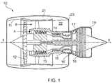
- a ducted fan gas turbine engine incorporating the invention is generally indicated at 10 and has a principal and rotational axis X-X.
- the engine comprises, in axial flow series, an air intake 11, a propulsive fan 12, an intermediate pressure compressor 13, a high-pressure compressor 14, combustion equipment 15, a high-pressure turbine 16, an intermediate pressure turbine 17, a low-pressure turbine 18 and a core engine exhaust nozzle 19.
- a nacelle 21 generally surrounds the engine 10 and defines the intake 11, a bypass duct 22 and a bypass exhaust nozzle 23.
- air entering the intake 11 is accelerated by the fan 12 to produce two air flows: a first air flow A into the intermediate-pressure compressor 13 and a second air flow B which passes through the bypass duct 22 to provide propulsive thrust.
- the intermediate-pressure compressor 13 compresses the air flow A directed into it before delivering that air to the high-pressure compressor 14 where further compression takes place.
- the compressed air exhausted from the high-pressure compressor 14 is directed into the combustion equipment 15 where it is mixed with fuel and the mixture combusted.
- the resultant hot combustion products then expand through, and thereby drive the high, intermediate and low-pressure turbines 16, 17, 18 before being exhausted through the nozzle 19 to provide additional propulsive thrust.
- the high, intermediate and low-pressure turbines respectively drive the high and intermediate-pressure compressors 14, 13 and the fan 12 by suitable interconnecting shafts.
- the fan 12 comprises a fan disc and a circumferential row of fan blades extending from the disc.
- Each blade has as a dovetail root 30 which is retained in a corresponding axially-extending slot 34 in the rim of the disc 32.
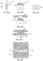
- Figure 2 shows schematically (a) an end-on view of a retention body 36 of the device, and (b) a longitudinal cross-section through the retention body along plane A-A.
- the retention body has a key portion 38 in the form of two spaced legs. These legs, in use, are received in spaced slots forming a keyway 40 shown schematically in Figure 2(c) , which is a plan view of part of the base of the slot 34 of the disc 32.
- the retention body 36 also has a mating portion 44 which forms an arc-shaped surface of the body.
- Figure 2(d) shows schematically a longitudinal cross-sectional view of the retention body 36, root 30 and disc 32 with the key portion 38 fully inserted in the keyway 40 such that the retention body is in a lowered position.
- the root has a complementary mating portion 46 with a correspondingly arc-shaped surface. The two mating portions are directly opposite each other when the root is fully inserted in the slot 34.
- the retention body 36 also has a chamfered lead-in portion 48 located between the two legs of the key portion 38.
- a slider 50 of the device is also inserted into the slot 34.
- the slider has a chamfered leading edge 52 which engages with the chamfered lead-in portion 48. Further insertion of the slider then pushes the retention body into a raised position, which is shown schematically in the longitudinal cross-sectional view of the retention body, root and disc of Figure 2(e) .
- the slider may have a low friction coating (formed e.g. of PTFE or polyimide) at the innermost and/or outermost surface thereof to facilitate its insertion.
- the retention body 36 urges the blade radially outwardly thereby mating flanks of the root 30 to flanks of the slot 34.
- the two mating portions 44, 46 mate with each other, their arc-shaped surfaces preventing relative axial movement between the retention body and the root. In this way, axial loads on the blade can be transmitted via its root to the retention body, and then transferred via shear at the key portion 38 and keyway 40 to the disc 32.
- the arc-shaped surfaces can reduce stress concentration in the root 30 by their gradual curvatures.
- the normal to the plane of the arc of each arc-shaped surface is substantially perpendicular to the engine axis (and conveniently also substantially perpendicular to the radial direction). This helps the mating portions 44, 46 to prevent relative axial movement between the retention body 36 and the root.
- the arc-shaped surfaces are also preferably shallow and in the complementary mating portion 46 do not break the root ends or flanks. Under extreme axial loading of the blade, the arc-shaped surfaces can help to redistribute some of the axial load as a compressive force driving the root 30 radially up in the slot 34.
- Figure 2(f) shows schematically a transverse section through the retention body 36, slider 50 root 30 and disc 32 with the retention body in the raised position.
- the slider can have plural prongs.
- the central prong provides the chamfered leading edge 52 and raises the retention body.
- Outer prongs can carry one or more chock springs 54 (e.g. metallic springs or rubber blocks) which also urge the blade radially outwardly.
- chock springs 54 e.g. metallic springs or rubber blocks
- Such springs can provide a useful damping function.
- the mating portion 44 of the retention body may have a relatively compliant outer layer for enhanced contact of the retention body with the root.
- the outer layer can be formed of an elastomer to improve damping, impact protection, and take up any tolerance between the root, rotor and retention body.
- the device may include a plurality of the retention bodies 36, each movable by the slider 50 from its lowered position to its raised position.
- the slot 34 may then similarly have a plurality of respective keyways 40.
- the keyways, and hence the retention bodies can be axially spaced along the slot.
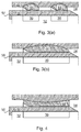
- Another option, shown schematically in Figure 3(b) is for the device to have a single retention body which extends almost the full length of the slot 34.
- Such a retention body could have a single key portion 38, as illustrated, or a plurality of axially spaced key portions located in respective keyways.
- the slider 50 can have a stop 56 which abuts against the external face of the disc 32 to prevent further insertion of the slider.
- the mating portion 44 can have a concave arc-shaped surface, rather than a convex arc-shaped surface.
Landscapes
- Engineering & Computer Science (AREA)
- Mechanical Engineering (AREA)
- General Engineering & Computer Science (AREA)
- Turbine Rotor Nozzle Sealing (AREA)
- Structures Of Non-Positive Displacement Pumps (AREA)
Abstract
A device for chocking and retaining a dovetail root (30) of a blade of a gas turbine engine (10) in a corresponding axially-extending slot (34) in a rim of a disc (32) includes a retention body (36) having a key portion (38) receivable in a keyway (40) formed in the base of the slot, and a mating portion (44) for mating with a complementary mating portion (46) of the root to prevent relative axial movement between the retention body and the root. The retention body has a lowered position in which the key portion is received sufficiently deeply in the keyway to allow the root to be positioned in the slot without interference from the retention body and also has a raised position in which, after the root is positioned in the slot, a part of the key portion is still received in the keyway while the mating portion mates with the complementary mating portion of the root. A slider (50) is axially insertable in the slot and moves the retention body from its lowered position to its raised position.

Description
- The present invention relates to a device for chocking and retaining a dovetail root of a blade of a gas turbine engine in a corresponding dovetail slot in the rim of a disc.
- Many aero-engines adopt a dovetail style of fan blade root which locates in a corresponding slot formed in the rim of the fan disc. During service operation, the fan assembly is subject to a complex loading system, consisting of centripetal load, gas-bending and vibration. The dovetail geometry copes particularly well with this kind of loading conditions.
- On assembly, the blades are "chocked" up to mate the flanks of the corresponding dovetail slots (in the absence of any centrifugal force when static) by inserting a slider beneath the blade root. When the rotor assembly is spinning, the blades are restrained radially by the dovetail slots, which are sized according to mechanical rules based on extreme load cases.
- To prevent the blades moving axially forward or rearward a number of approaches can be employed. One is to use a solid block or plate of metal inserted into machined grooves in the disc either at the front and back of the dovetail slot or mid slot (which requires a corresponding groove machined into the blade root). This approach relies on the shear strength of the plates (and disc grooves) to withstand any axial force placed on them. The plates are sized on the worst case of either large bird impact or trailing blade impact following a fan blade off event.
- The large forces seen during these extreme cases lead to a thick plate design and a correspondingly large extension of the disc. This requires larger and more expensive disc forging and increases the disc machining time. In addition, the extension: adds weight and therefore increases specific fuel consumption; can use up engine space and encroach on adjacent components; and can lead to pumping and windage, creating a secondary airflow and associated temperature increase. Further, the shear plate produces a larger part count, which increases costs and assembly time.
- The mid slot approach requires machining of the blade root to accommodate the plate, which breaks through the dovetail flanks. This can be acceptable in the case of a metal blade, but may cause issues in a composite blade, where the groove in the blade root is typically perpendicular to the fibre plies in the root and has sharp edges, which may cause stress concentrations. Breaking the flanks can also require the blade root to be extended axially to meet acceptable crushing stress limits (which again lead to a corresponding increase in disc axial length).
- Current blade retention approaches also offer little vibrational damping to the blade or disc.
- In a first aspect, the present invention provides a device for chocking and retaining a dovetail root of a blade of a gas turbine engine in a corresponding axially-extending slot in the rim of a disc, the device including:
- a retention body having a key portion receivable in a keyway formed in the base of the slot, and a mating portion for mating with a complementary mating portion of the root to prevent relative axial movement between the retention body and the root, the retention body having a lowered position in which the key portion is received sufficiently deeply in the keyway to allow the root to be positioned in the slot without interference from the retention body, and a raised position in which, after the root is positioned in the slot, a part of the key portion is still received in the keyway while the mating portion mates with the complementary mating portion of the root;
- a slider which is axially insertable in the slot;
- wherein the slider and the retention body are configured so that, on axial insertion of the slider in the slot after the root is positioned in the slot, the slider moves the retention body from its lowered position to its raised position, whereby the retention body urges the blade radially outwardly thereby mating flanks of the root to flanks of the slot, while the part of the key portion still received in the keyway retains the root axially in the slot.
- Advantageously, the retention body can be retained within the forging envelope of the disc, and does not require any extension of the disc, saving on forging and machining costs and weight. Further, the retention body is compatible with composite blades, not requiring any break in the flanks of the blade root. The cross sectional profile of the retention body can be configured for shear strength, compressive/bucking strength, weight and vibrational response. Under extreme axial loading, impact energy can be dissipated through shear and compressive forces between the retention body, blade root and disc, rather than pure shear as with a conventional retaining plate.
- In a second aspect, the present invention provides a rotor assembly of a gas turbine engine, the assembly having:
- a disc;
- a circumferential row of blades (e.g. composite blades), each blade having a dovetail root which is retained in a corresponding axially-extending slot in the rim of the disc; and
- a plurality of devices according to the first aspect for chocking and retaining the dovetail roots of the blades in the slots;
- wherein each slot has a keyway formed in the base thereof, the key portion of the retention body of each device is received in a respective one of the keyways, and the slider of each device is inserted in a respective one of the slots to move its retention body to the raised position.
- For example, the assembly can be a fan assembly, with the blades being fan blades, and the disc being a fan disc.
- In a third aspect, the present invention provides a gas turbine engine having the rotor assembly of the second aspect.
- Optional features of the invention will now be set out. These are applicable singly or in any combination with any aspect of the invention.
- The key portion may comprise one or more legs and the keyway comprises one or more slots for respectively receiving the legs. For example, the key portion may have two legs, and the keyway two slots. The slider can then insert between the two legs to move the retention body from its lowered position to its raised position.
- The retention body may have a chamfered lead-in portion against which the slider slides on axial insertion of the slider in the slot to move the retention body from its lowered position to its raised position. The chamfered lead-in portion can facilitate the action of the slider on the retention body.
- The slider may have a chamfered or rounded leading edge. This can also facilitate the action of the slider on the retention body.
- The mating portion may form an arc-shaped surface of the retention body and the complementary mating portion may form a correspondingly arc-shaped surface of the root, the normal to the plane of the arc of each arc-shaped surface being substantially perpendicular to the engine axis, whereby the arc-shaped surfaces mate to prevent relative axial movement between the retention body and the root. Such shapes allow the complementary mating portion to be a shallow feature of the root which does not break the flanks or ends of the root. It is thus suitable for retaining and chocking a composite blade. Under extreme axial loading, impact energy is dissipated through shear resistance at the part of the key portion which is still received in the keyway. However, such shapes also allow some energy to be redistributed as compressive force into the dovetail root. The normal to the plane of each arc may be substantially perpendicular to the radial direction. The arc-shaped surface of the retention body can be a convex or a concave surface.
- The mating portion of the retention body may have a relatively compliant outer layer for enhanced contact of the retention body with the root. Thus, for example, the outer layer can be formed of an elastomer. In contrast, the key portion of the retention body can be relatively rigid (being formed e.g. of metal or composite material). The compliant layer can provide damping, impact protection, and take up any tolerance between the root, rotor and retention body.
- The slider may have a low friction coating (formed e.g. of PTFE or polyimide) at the innermost and/or outermost surface thereof to facilitate its insertion.
- The slider may have one or more chock springs which are arranged to act, in use, on the root to also urge the blade radially outwardly. For example, the chock spring(s) can be located to act on the root to both sides of the complementary mating portion.
- The device may include a plurality of the retention bodies, each movable by the slider from its lowered position to its raised position. The slot may similarly have a plurality of respective keyways. For example, the keyways, and hence the retention bodies, can be axially spaced along the slot.
- The slider may have a stop at an end thereof which, in use, abuts a face of the disc or the root when the slider is fully inserted in the slot to prevent over-insertion of the slider. For example, the stop can be a flange which abuts an external face of the disc and/or the root. Another option is for the stop to abut a surface, such as a flat, provided by the disc and/or the root within the slot.
- Generally, the dovetail root and slot are straight, but a curved root and slot are not precluded.
- Embodiments of the invention will now be described by way of example with reference to the accompanying drawings in which:
-
Figure 1 shows a longitudinal cross-section through a ducted fan gas turbine engine; -
Figure 2 shows schematically (a) an end-on view of a retention body of a device for chocking and retaining a dovetail root of a blade of a gas turbine engine in a corresponding axially-extending slot in the rim of a disc, (b) a longitudinal cross-section through the retention body along plane A-A, (c) a plan view of a keyway formed in the base of the slot, (d) a longitudinal cross-sectional view of the retention body, root and disc with the retention body in a lowered position, (e) a longitudinal cross-sectional view of the retention body, root and disc with the retention body moved to a raised position by a slider, and (f) a transverse section through the retention body, slider, root and disc with the retention body in the raised position; -
Figure 3 shows schematically (a) a longitudinal cross-sectional view of two retention bodies, a root and a disc with the retention bodies in raised positions, and (b) a longitudinal cross-sectional view of a single retention body, a root and a disc with the retention body in the raised position; and -
Figure 4 shows schematically a longitudinal cross-sectional view of a variant single retention body, a root and a disc with the retention body in the raised position. - With reference to
Figure 1 , a ducted fan gas turbine engine incorporating the invention is generally indicated at 10 and has a principal and rotational axis X-X. The engine comprises, in axial flow series, anair intake 11, apropulsive fan 12, anintermediate pressure compressor 13, a high-pressure compressor 14,combustion equipment 15, a high-pressure turbine 16, anintermediate pressure turbine 17, a low-pressure turbine 18 and a coreengine exhaust nozzle 19. Anacelle 21 generally surrounds theengine 10 and defines theintake 11, abypass duct 22 and abypass exhaust nozzle 23. - During operation, air entering the
intake 11 is accelerated by thefan 12 to produce two air flows: a first air flow A into the intermediate-pressure compressor 13 and a second air flow B which passes through thebypass duct 22 to provide propulsive thrust. The intermediate-pressure compressor 13 compresses the air flow A directed into it before delivering that air to the high-pressure compressor 14 where further compression takes place. - The compressed air exhausted from the high-
pressure compressor 14 is directed into thecombustion equipment 15 where it is mixed with fuel and the mixture combusted. The resultant hot combustion products then expand through, and thereby drive the high, intermediate and low-pressure turbines nozzle 19 to provide additional propulsive thrust. The high, intermediate and low-pressure turbines respectively drive the high and intermediate-pressure compressors fan 12 by suitable interconnecting shafts. - The
fan 12 comprises a fan disc and a circumferential row of fan blades extending from the disc. Each blade has as adovetail root 30 which is retained in a corresponding axially-extendingslot 34 in the rim of thedisc 32. To chock the flanks of roots radially outwardly against the flanks of the slots, and to retain the roots axially within the slots, each blade has a chocking and retaining device according to the present invention. -
Figure 2 shows schematically (a) an end-on view of aretention body 36 of the device, and (b) a longitudinal cross-section through the retention body along plane A-A. The retention body has akey portion 38 in the form of two spaced legs. These legs, in use, are received in spaced slots forming akeyway 40 shown schematically inFigure 2(c) , which is a plan view of part of the base of theslot 34 of thedisc 32. Theretention body 36 also has amating portion 44 which forms an arc-shaped surface of the body. -
Figure 2(d) shows schematically a longitudinal cross-sectional view of theretention body 36,root 30 anddisc 32 with thekey portion 38 fully inserted in thekeyway 40 such that the retention body is in a lowered position. This allows the root to be slid along the axially-extendingslot 34 without interference from the retention body. The root has acomplementary mating portion 46 with a correspondingly arc-shaped surface. The two mating portions are directly opposite each other when the root is fully inserted in theslot 34. - The
retention body 36 also has a chamfered lead-inportion 48 located between the two legs of thekey portion 38. With theroot 30 fully inserted in theslot 34, aslider 50 of the device is also inserted into theslot 34. The slider has a chamfered leadingedge 52 which engages with the chamfered lead-inportion 48. Further insertion of the slider then pushes the retention body into a raised position, which is shown schematically in the longitudinal cross-sectional view of the retention body, root and disc ofFigure 2(e) . The slider may have a low friction coating (formed e.g. of PTFE or polyimide) at the innermost and/or outermost surface thereof to facilitate its insertion. - In the raised position, the
retention body 36 urges the blade radially outwardly thereby mating flanks of theroot 30 to flanks of theslot 34. Moreover, the twomating portions key portion 38 andkeyway 40 to thedisc 32. - Advantageously, the arc-shaped surfaces can reduce stress concentration in the
root 30 by their gradual curvatures. Generally, the normal to the plane of the arc of each arc-shaped surface is substantially perpendicular to the engine axis (and conveniently also substantially perpendicular to the radial direction). This helps themating portions retention body 36 and the root. The arc-shaped surfaces are also preferably shallow and in thecomplementary mating portion 46 do not break the root ends or flanks. Under extreme axial loading of the blade, the arc-shaped surfaces can help to redistribute some of the axial load as a compressive force driving theroot 30 radially up in theslot 34. -
Figure 2(f) shows schematically a transverse section through theretention body 36,slider 50root 30 anddisc 32 with the retention body in the raised position. The slider can have plural prongs. The central prong provides the chamfered leadingedge 52 and raises the retention body. Outer prongs can carry one or more chock springs 54 (e.g. metallic springs or rubber blocks) which also urge the blade radially outwardly. Such springs can provide a useful damping function. Indeed, themating portion 44 of the retention body may have a relatively compliant outer layer for enhanced contact of the retention body with the root. For example, the outer layer can be formed of an elastomer to improve damping, impact protection, and take up any tolerance between the root, rotor and retention body. - As shown schematically in
Figure 3(a) , the device may include a plurality of theretention bodies 36, each movable by theslider 50 from its lowered position to its raised position. Theslot 34 may then similarly have a plurality ofrespective keyways 40. For example, the keyways, and hence the retention bodies, can be axially spaced along the slot. Another option, shown schematically inFigure 3(b) , is for the device to have a single retention body which extends almost the full length of theslot 34. Such a retention body could have a singlekey portion 38, as illustrated, or a plurality of axially spaced key portions located in respective keyways. - As shown in
Figures 3(a) and (b) , theslider 50 can have astop 56 which abuts against the external face of thedisc 32 to prevent further insertion of the slider. - As shown in
Figure 4 , themating portion 44 can have a concave arc-shaped surface, rather than a convex arc-shaped surface. - While the invention has been described in conjunction with the exemplary embodiments described above, many equivalent modifications and variations will be apparent to those skilled in the art when given this disclosure. Accordingly, the exemplary embodiments of the invention set forth above are considered to be illustrative and not limiting. Various changes to the described embodiments may be made without departing from the scope of the invention.
Claims (14)
- A device for chocking and retaining a dovetail root (30) of a blade of a gas turbine engine (10) in a corresponding axially-extending slot (34) in the rim of a disc (32), the device including:a retention body (36) having a key portion (38) receivable in a keyway (40) formed in the base of the slot, and a mating portion (44) for mating with a complementary mating portion (46) of the root to prevent relative axial movement between the retention body and the root, the retention body having a lowered position in which the key portion is received sufficiently deeply in the keyway to allow the root to be positioned in the slot without interference from the retention body, and a raised position in which, after the root is positioned in the slot, a part of the key portion is still received in the keyway while the mating portion mates with the complementary mating portion of the root;a slider (50) which is axially insertable in the slot;wherein the slider and the retention body are configured so that, on axial insertion of the slider in the slot after the root is positioned in the slot, the slider moves the retention body from its lowered position to its raised position, whereby the retention body urges the blade radially outwardly thereby mating flanks of the root to flanks of the slot, while the part of the key portion still received in the keyway retains the root axially in the slot.
- A device according to claim 1, wherein the key portion comprises one or more legs and the keyway comprises one or more slots for respectively receiving the legs.
- A device according to claim 1 or 2, wherein the retention body has a chamfered lead-in portion (48) against which the slider slides on axial insertion of the slider in the slot to move the retention body from its lowered position to its raised position.
- A device according to any one of the previous claims, wherein the slider has a chamfered or rounded leading edge (52).
- A device according to any one of the previous claims, wherein the mating portion forms an arc-shaped surface of the retention body and the complementary mating portion forms a correspondingly arc-shaped surface of the root, the normal to the plane of the arc of each arc-shaped surface being substantially perpendicular to the engine axis, whereby the arc-shaped surfaces mate to prevent relative axial movement between the retention body and the root.
- A device according to claim 5, wherein the normal to the plane of each arc is substantially perpendicular to the radial direction.
- A device according to claim 5 or 6, wherein the arc-shaped surface of the retention body is a convex surface.
- A device according to claim 5 or 6, wherein the arc-shaped surface of the retention body is a concave surface.
- A device according to any one of the previous claims, wherein of the mating portion of the retention body has a relatively compliant outer layer for enhanced contact of the retention body with the root.
- A device according to any one of the previous claims, wherein the slider has one or more chock springs (54) which are arranged to act, in use, on the root to also urge the blade radially outwardly.
- A device according to any one of the previous claims, wherein the slider has a stop (56) at an end thereof which, in use, abuts a face of the disc or the root when the slider is fully inserted in the slot to prevent over-insertion of the slider.
- A device according to any one of the previous claims including a plurality of the retention bodies, each movable by the slider from its lowered position to its raised position.
- A rotor assembly of a gas turbine engine (10), the assembly having:a disc (32);a circumferential row of blades, each blade having a dovetail root (30) which is retained in a corresponding axially-extending slot (34) in the rim of the disc; anda plurality of devices according to any one of the previous claims for chocking and retaining the dovetail roots of the blades in the slots;wherein each slot has a keyway formed in the base thereof, the key portion of the retention body of each device is received in a respective one of the keyways, and the slider of each device is inserted in a respective one of the slots to move its retention body to the raised position.
- A gas turbine engine (10) having the rotor assembly of claim 13.
Applications Claiming Priority (1)
| Application Number | Priority Date | Filing Date | Title |
|---|---|---|---|
| GB201504182A GB201504182D0 (en) | 2015-03-12 | 2015-03-12 | Chocking and retaining device |
Publications (1)
| Publication Number | Publication Date |
|---|---|
| EP3070269A1 true EP3070269A1 (en) | 2016-09-21 |
Family
ID=53016009
Family Applications (1)
| Application Number | Title | Priority Date | Filing Date |
|---|---|---|---|
| EP16157682.2A Withdrawn EP3070269A1 (en) | 2015-03-12 | 2016-02-26 | Chocking and retaining device |
Country Status (3)
| Country | Link |
|---|---|
| US (1) | US10145250B2 (en) |
| EP (1) | EP3070269A1 (en) |
| GB (1) | GB201504182D0 (en) |
Families Citing this family (10)
| Publication number | Priority date | Publication date | Assignee | Title |
|---|---|---|---|---|
| US10569481B2 (en) | 2017-06-26 | 2020-02-25 | General Electric Company | Shaped composite ply layups and methods for shaping composite ply layups |
| US10677075B2 (en) | 2018-05-04 | 2020-06-09 | General Electric Company | Composite airfoil assembly for an interdigitated rotor |
| US10941665B2 (en) | 2018-05-04 | 2021-03-09 | General Electric Company | Composite airfoil assembly for an interdigitated rotor |
| US11040915B2 (en) | 2018-09-11 | 2021-06-22 | General Electric Company | Method of forming CMC component cooling cavities |
| US10934854B2 (en) | 2018-09-11 | 2021-03-02 | General Electric Company | CMC component cooling cavities |
| US11066936B1 (en) | 2020-05-07 | 2021-07-20 | Rolls-Royce Corporation | Turbine bladed disc brazed sealing plate with flow metering and axial retention features |
| US11156110B1 (en) | 2020-08-04 | 2021-10-26 | General Electric Company | Rotor assembly for a turbine section of a gas turbine engine |
| KR102355521B1 (en) * | 2020-08-19 | 2022-01-24 | 두산중공업 주식회사 | Assembling structure of compressor blade and gas turbine comprising the same and assembling method of compressor blade |
| US11655719B2 (en) | 2021-04-16 | 2023-05-23 | General Electric Company | Airfoil assembly |
| CN115853689B (en) * | 2022-12-09 | 2025-08-15 | 中国船舶集团有限公司第七一一研究所 | Turbine assembly and turbine starting device |
Citations (5)
| Publication number | Priority date | Publication date | Assignee | Title |
|---|---|---|---|---|
| WO2000031378A1 (en) * | 1998-11-23 | 2000-06-02 | Pratt & Whitney Canada Corp. | Turbine blade to disk retention device |
| EP1905957A1 (en) * | 2006-09-27 | 2008-04-02 | Siemens Aktiengesellschaft | Locking device of a turbine blade |
| US20110052399A1 (en) * | 2009-08-28 | 2011-03-03 | Rolls-Royce Plc | Aerofoil blade assembly |
| US20120177498A1 (en) * | 2011-01-07 | 2012-07-12 | General Electric Company | Axial retention device for turbine system |
| US20130156591A1 (en) * | 2011-12-16 | 2013-06-20 | United Technologies Corporation | Energy absorbent fan blade spacer |
Family Cites Families (6)
| Publication number | Priority date | Publication date | Assignee | Title |
|---|---|---|---|---|
| US4621979A (en) * | 1979-11-30 | 1986-11-11 | United Technologies Corporation | Fan rotor blades of turbofan engines |
| US5123813A (en) * | 1991-03-01 | 1992-06-23 | General Electric Company | Apparatus for preloading an airfoil blade in a gas turbine engine |
| FR2728299B1 (en) * | 1994-12-14 | 1997-01-24 | Snecma | DEVICE FOR AXIAL FIXING OF TURBO-SPINDLE ROTOR BLADES |
| FR2807096B1 (en) * | 2000-03-30 | 2002-05-31 | Abb Alstom Power Nv | ROTOR DISC OF TURBINE EQUIPPED WITH FINS ON FOOT AND TREE OF MOUNTING A FIN ON A DISC |
| FR2881174B1 (en) * | 2005-01-27 | 2010-08-20 | Snecma Moteurs | DEVICE FOR POSITIONING A DASHBOARD AND AUBAGE DISK COMPRISING SUCH A DEVICE |
| US8186961B2 (en) * | 2009-01-23 | 2012-05-29 | Pratt & Whitney Canada Corp. | Blade preloading system |
-
2015
- 2015-03-12 GB GB201504182A patent/GB201504182D0/en not_active Ceased
-
2016
- 2016-02-26 EP EP16157682.2A patent/EP3070269A1/en not_active Withdrawn
- 2016-03-01 US US15/057,407 patent/US10145250B2/en not_active Expired - Fee Related
Patent Citations (5)
| Publication number | Priority date | Publication date | Assignee | Title |
|---|---|---|---|---|
| WO2000031378A1 (en) * | 1998-11-23 | 2000-06-02 | Pratt & Whitney Canada Corp. | Turbine blade to disk retention device |
| EP1905957A1 (en) * | 2006-09-27 | 2008-04-02 | Siemens Aktiengesellschaft | Locking device of a turbine blade |
| US20110052399A1 (en) * | 2009-08-28 | 2011-03-03 | Rolls-Royce Plc | Aerofoil blade assembly |
| US20120177498A1 (en) * | 2011-01-07 | 2012-07-12 | General Electric Company | Axial retention device for turbine system |
| US20130156591A1 (en) * | 2011-12-16 | 2013-06-20 | United Technologies Corporation | Energy absorbent fan blade spacer |
Also Published As
| Publication number | Publication date |
|---|---|
| US20160265370A1 (en) | 2016-09-15 |
| GB201504182D0 (en) | 2015-04-29 |
| US10145250B2 (en) | 2018-12-04 |
Similar Documents
| Publication | Publication Date | Title |
|---|---|---|
| US10145250B2 (en) | Chocking and retaining device | |
| US8826536B2 (en) | Blade preloading method | |
| US9297258B2 (en) | Trapped spring balance weight and rotor assembly | |
| US10024178B2 (en) | Chocking and retaining device | |
| EP1650406B1 (en) | Locking assembly for a gas turbine rotor stage | |
| EP3219910B1 (en) | Disc for a rotor of a gas turbine engine, and a rotor and a gas turbine comprising the same | |
| EP3170988B1 (en) | Rotor for gas turbine engine | |
| US9410440B2 (en) | Rotor assembly | |
| EP3219912B1 (en) | Cover plate, rotor assembly, and gas turbine | |
| US10221705B2 (en) | Slider for chocking a dovetail root of a blade of a gas turbine engine | |
| EP3363993B1 (en) | Fan and corresponding gas turbine engine | |
| US10428662B2 (en) | Retention device | |
| EP3299581A1 (en) | Gas turbine engine | |
| EP3219909B1 (en) | Disc for a gas turbine engine, rotor assembly, and gas turbine | |
| JP6027224B2 (en) | Trap balance weight and rotor assembly | |
| EP3219908B1 (en) | Disc for a rotor assembly of a gas turbine, rotor assembly, and gas turbine | |
| EP3333378A1 (en) | Nut anti-rotation via an insert |
Legal Events
| Date | Code | Title | Description |
|---|---|---|---|
| PUAI | Public reference made under article 153(3) epc to a published international application that has entered the european phase |
Free format text: ORIGINAL CODE: 0009012 |
|
| AK | Designated contracting states |
Kind code of ref document: A1 Designated state(s): AL AT BE BG CH CY CZ DE DK EE ES FI FR GB GR HR HU IE IS IT LI LT LU LV MC MK MT NL NO PL PT RO RS SE SI SK SM TR |
|
| AX | Request for extension of the european patent |
Extension state: BA ME |
|
| STAA | Information on the status of an ep patent application or granted ep patent |
Free format text: STATUS: THE APPLICATION HAS BEEN PUBLISHED |
|
| STAA | Information on the status of an ep patent application or granted ep patent |
Free format text: STATUS: THE APPLICATION IS DEEMED TO BE WITHDRAWN |
|
| 18D | Application deemed to be withdrawn |
Effective date: 20170322 |