EP3069906A1 - Suspension arm - Google Patents
Suspension arm Download PDFInfo
- Publication number
- EP3069906A1 EP3069906A1 EP14861329.2A EP14861329A EP3069906A1 EP 3069906 A1 EP3069906 A1 EP 3069906A1 EP 14861329 A EP14861329 A EP 14861329A EP 3069906 A1 EP3069906 A1 EP 3069906A1
- Authority
- EP
- European Patent Office
- Prior art keywords
- arm body
- drive shaft
- side attachment
- arm
- suspension arm
- Prior art date
- Legal status (The legal status is an assumption and is not a legal conclusion. Google has not performed a legal analysis and makes no representation as to the accuracy of the status listed.)
- Granted
Links
- 239000000725 suspension Substances 0.000 title claims abstract description 36
- 238000010438 heat treatment Methods 0.000 claims description 14
- 238000010791 quenching Methods 0.000 claims description 8
- 230000000171 quenching effect Effects 0.000 claims description 8
- 238000005452 bending Methods 0.000 abstract 1
- 238000005728 strengthening Methods 0.000 description 4
- 230000008878 coupling Effects 0.000 description 3
- 238000010168 coupling process Methods 0.000 description 3
- 238000005859 coupling reaction Methods 0.000 description 3
- 238000000034 method Methods 0.000 description 3
- 229910000831 Steel Inorganic materials 0.000 description 2
- 238000005336 cracking Methods 0.000 description 2
- 230000000694 effects Effects 0.000 description 2
- 239000013013 elastic material Substances 0.000 description 2
- 239000010959 steel Substances 0.000 description 2
- 230000002452 interceptive effect Effects 0.000 description 1
- 238000005121 nitriding Methods 0.000 description 1
Images


Classifications
-
- B—PERFORMING OPERATIONS; TRANSPORTING
- B60—VEHICLES IN GENERAL
- B60G—VEHICLE SUSPENSION ARRANGEMENTS
- B60G7/00—Pivoted suspension arms; Accessories thereof
- B60G7/001—Suspension arms, e.g. constructional features
-
- B—PERFORMING OPERATIONS; TRANSPORTING
- B60—VEHICLES IN GENERAL
- B60G—VEHICLE SUSPENSION ARRANGEMENTS
- B60G2206/00—Indexing codes related to the manufacturing of suspensions: constructional features, the materials used, procedures or tools
- B60G2206/01—Constructional features of suspension elements, e.g. arms, dampers, springs
- B60G2206/016—Constructional features of suspension elements, e.g. arms, dampers, springs allowing controlled deformation during collision
-
- B—PERFORMING OPERATIONS; TRANSPORTING
- B60—VEHICLES IN GENERAL
- B60G—VEHICLE SUSPENSION ARRANGEMENTS
- B60G2206/00—Indexing codes related to the manufacturing of suspensions: constructional features, the materials used, procedures or tools
- B60G2206/01—Constructional features of suspension elements, e.g. arms, dampers, springs
- B60G2206/10—Constructional features of arms
-
- B—PERFORMING OPERATIONS; TRANSPORTING
- B60—VEHICLES IN GENERAL
- B60G—VEHICLE SUSPENSION ARRANGEMENTS
- B60G2206/00—Indexing codes related to the manufacturing of suspensions: constructional features, the materials used, procedures or tools
- B60G2206/01—Constructional features of suspension elements, e.g. arms, dampers, springs
- B60G2206/10—Constructional features of arms
- B60G2206/11—Constructional features of arms the arm being a radius or track or torque or steering rod or stabiliser end link
-
- B—PERFORMING OPERATIONS; TRANSPORTING
- B60—VEHICLES IN GENERAL
- B60G—VEHICLE SUSPENSION ARRANGEMENTS
- B60G2206/00—Indexing codes related to the manufacturing of suspensions: constructional features, the materials used, procedures or tools
- B60G2206/01—Constructional features of suspension elements, e.g. arms, dampers, springs
- B60G2206/10—Constructional features of arms
- B60G2206/122—Constructional features of arms the arm having L-shape
-
- B—PERFORMING OPERATIONS; TRANSPORTING
- B60—VEHICLES IN GENERAL
- B60G—VEHICLE SUSPENSION ARRANGEMENTS
- B60G2206/00—Indexing codes related to the manufacturing of suspensions: constructional features, the materials used, procedures or tools
- B60G2206/01—Constructional features of suspension elements, e.g. arms, dampers, springs
- B60G2206/70—Materials used in suspensions
- B60G2206/72—Steel
-
- B—PERFORMING OPERATIONS; TRANSPORTING
- B60—VEHICLES IN GENERAL
- B60G—VEHICLE SUSPENSION ARRANGEMENTS
- B60G2206/00—Indexing codes related to the manufacturing of suspensions: constructional features, the materials used, procedures or tools
- B60G2206/01—Constructional features of suspension elements, e.g. arms, dampers, springs
- B60G2206/80—Manufacturing procedures
- B60G2206/81—Shaping
- B60G2206/8106—Shaping by thermal treatment, e.g. curing hardening, vulcanisation
Definitions
- the present invention relates to suspension arms, and more particularly to an improvement in suspension arm that is mounted near a drive shaft.
- a vehicle suspension arm which includes (a) an arm body having a longitudinal shape, (b) a wheel-side attachment portion that is disposed at one end of the arm body and coupled to the upper part of an axle carrier, and (c) a vehicle body-side attachment portion that is disposed at the other end of the arm body and coupled to a vehicle body.
- Patent Document 1 describes a technique of strengthening a curved portion of an arm body by heat treatment etc.
- Patent Document 1 Japanese Patent Application Publication No. 2010-260513
- the present invention was developed in view of the above circumstances, and it is an object of the present invention to prevent an arm body of a suspension arm that is mounted near a drive shaft from interfering with the drive shaft in the case where the arm body is deformed by a load.
- a first aspect of the invention provides a suspension arm, which includes (a) an arm body having a longitudinal shape, (b) a wheel-side attachment portion that is disposed at one end of the arm body and coupled to an upper part of an axle carrier, and (c) a vehicle body-side attachment portion that is disposed at the other end of the arm body and coupled to a vehicle body, and which (d) is mounted near a drive shaft so as to extend in a lateral direction of a vehicle, the suspension arm characterized in that (e) the arm body includes an overlap portion that overlaps the drive shaft as viewed from a front in a longitudinal direction of a vehicle, and (f) a weak portion having lower strength than the overlap portion is provided between the overlap portion and the wheel-side attachment portion.
- a second aspect of the invention provides the suspension arm recited in the first aspect of the invention, characterized in that the overlap portion has higher strength than the weak portion by quenching treatment using high frequency heating.
- a third aspect of the invention provides the suspension arm recited in the first or second aspect of the invention, characterized in that (a) the wheel-side attachment portion and the vehicle body-side attachment portion are coupled at positions above the drive shaft as viewed from the front, and (b) the arm body includes a curved portion located on its vehicle body-side attachment portion side and curved so as to protrude toward a lower side of the vehicle, and a lower end of the curved portion serves as the overlap portion.
- a fourth aspect of the invention provides the suspension arm recited in any one of the first to third aspects of the invention, characterized in that the weak portion is partially provided at an intermediate position between the overlap portion and the wheel-side attachment portion, and portions on both sides of the weak portion have higher strength than the weak portion.
- the weak portion is provided between the overlap portion and the wheel-side attachment portion of the arm body. Accordingly, when the suspension arm is subjected to an excessive load, the weak portion is preferentially deformed. This prevents interference of the overlap portion with the drive shaft due to deformation of the overlap portion.
- the overlap portion since the overlap portion has high strength by quenching using high frequency heating, this appropriately prevents interference of the overlap portion with the drive shaft due to deformation of the overlap portion. Since the arm body is strengthened by quenching, the strength continuously varies in the boundary portions with the weak portion that is not strengthened. This restrains stress concentration due to a change in strength and thus restrains breakage and cracking.
- the third aspect of the invention is the case where the arm body includes the curved portion that protrudes toward the lower side of the vehicle. Since the lower end of the curved portion serves as the overlap portion, the curved portion is likely to be deformed and interfere with the drive shaft if the arm body has uniform strength. Applying the present invention to the suspension arm thus provides a significant effect of the present invention, namely prevents interference of the curved portion with the drive shaft.
- the weak portion is partially provided at the intermediate position between the overlap portion and the wheel-side attachment portion, and the portions on both sides of the weak portion have relatively high strength.
- the weak portion is thus more reliably preferentially deformed by a load, which more appropriately prevents interference of the overlap portion with the drive shaft due to deformation of the overlap portion.
- an arm body made of a high tensile steel plate, a round pipe, a square or rectangular pipe, etc. and having a hollow longitudinal shape is preferably used as the arm body of the suspension arm of the present invention.
- This arm body has tensile strength as high as about 1,000 to 1,500 MPa by strengthening such as quenching, and a part of the arm body which is not strengthened has tensile strength of about 500 to 700 MPa.
- the weak portion can thus be provided depending whether the strengthening is performed or not.
- each of the wheel-side attachment portion and the vehicle body-side attachment portion is composed by a cylindrical bush having an elastic material placed therein, and an attachment shaft that is inserted into an attachment hole of the bush, etc.
- the overlap portion has high strength by quenching using high frequency heating.
- other heating methods or other strengthening techniques such as nitriding may be used. It is desirable to strengthen not just the overlap portion but the entire arm body except the weak portion. However, only the overlap portion may be strengthened, and the strength of the entire arm body except the overlap portion may be as low as that of the weak portion.
- the weak portion may be provided by varying the sectional shape of the arm body such as partially reducing the thickness of the arm body. Alternatively, the overlap portion may be strengthened by varying the sectional shape of the arm body such as partially increasing the thickness of the overlap portion.
- the arm body includes the curved portion that protrudes toward the lower side of the vehicle.
- the shape of the arm body is decided as appropriate, and the present invention is applicable to the case where the arm body has the overlap portion that overlaps the drive shaft as viewed from the front.
- FIG. 1 is a front view of a vehicle suspension arm 10 to which the present invention is applied, as viewed in the longitudinal direction of a vehicle.
- the right side in FIG. 1 is the wheel side
- the left side in FIG. 1 is the vehicle body side, namely the side toward the middle of the vehicle in the lateral direction where a differential is disposed.
- FIG. 2 is a plan view of the suspension arm 10 as viewed from above the vehicle.
- the suspension arm 10 is mounted near a drive shaft 12 so as to extend in the lateral direction of the vehicle, and includes an arm body 14 having a longitudinal shape, a wheel-side attachment portion 16 disposed at one end of the arm body 14, and a vehicle body-side attachment portion 18 disposed at the other end of the arm body.
- Each of the wheel-side attachment portion 16 and the vehicle body-side attachment portion 18 is a cylindrical bush having an elastic material placed therein.
- the wheel-side attachment portion 16 is coupled to the upper part of an axle carrier 22 via a coupling shaft 20, and the vehicle body-side attachment portion 18 is coupled to a vehicle body via a coupling shaft 24.
- the wheel-side attachment portion 16 and the vehicle body-side attachment portion 18 are coupled to the coupling shafts 20, 24 at positions above the drive shaft 12 as viewed from the front as shown in FIG. 1 .
- the arm body 14 is made of a high tensile steel plate and has a hollow longitudinal shape with a rectangular or elliptical sectional shape that is longer in the vertical direction.
- the arm body 14 is placed in such an attitude that the arm body 14 extends substantially parallel to the drive shaft 12 as viewed in plan as shown in FIG. 2 .
- the arm body 14 has a curved portion 26 on its vehicle body-side attachment portion 18 side, and the curved portion 26 is curved so as to protrude toward the lower side of the vehicle.
- a lower end 26r of the curved portion 26 overlaps the drive shaft 12 as viewed from the front as shown in FIG. 1 .
- the lower end 26r corresponds to an overlap portion.
- the entire arm body 14 except a weak portion 28 (shaded area) defined at an intermediate position between the curved portion 26 and the wheel-side attachment portion 16 is quenched by high frequency heating so as to have tensile strength as high as about 1,400 to 1,500 MPa.
- the high frequency heating is performed by switching on and off a power supply thereof, and the weak portion 28 that is not heated has tensile strength of about 550 to 650 MPa.
- the entire arm body 14 except the weak portion 28 is thus quenched so as to have high strength.
- the heating temperature continuously varies in boundary portions on both sides of the weak portion 28, and the tensile strength thus continuously varies in these boundary portions.
- the weak portion 28 is designed to be located above the drive shaft 12 as viewed from the front as shown in FIG. 1 .
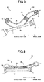
- the weak portion 28 is provided between the curved portion 26 and the wheel-side attachment portion 16 of the arm body 14. Accordingly, when the suspension arm 10 is subjected to an excessive load, the weak portion 28 is preferentially deformed as shown in FIGS. 3 and 4 . This prevents interference of the lower end 26r with the drive shaft 12 due to deformation of the curved portion 26. If a suspension arm has the same shape as the suspension arm 10 and an arm body 14 of the suspension arm has substantially uniform strength, the arm body 14 is bent and buckled in the curved portion 26 as shown in FIGS. 5 and 6 when subjected to an excessive load, as stress concentration tends to occur in the curved portion 26 in terms of the shape. The lower end 26r may therefore interfere with and damage the drive shaft 12.
- the curved portion 26 has high strength by quenching using high frequency heating, this appropriately prevents interference of the lower end 26r with the drive shaft 12 due to deformation of the curved portion 26.
- the arm body 14 is strengthened by quenching, the strength continuously varies in the boundary portions with the weak portion 28 that is not strengthened. This restrains stress concentration due to a change in strength and thus restrains breakage and cracking.
- the strength can be varied merely by whether heat treatment is performed or not. Unlike conventional heat treatment, the strength can be varied by merely not performing heat treatment on the weak portion 28. This requires no additional cost as compared to the case where the strength is varied by varying the thickness and the sectional shape. The strength can thus be varied easily and inexpensively.
- the weak portion 28 is partially provided at the intermediate position between the curved portion 26 and the wheel-side attachment portion 16, and the portions on both sides of the weak portion 28 have relatively high strength.
- the weak portion 28 is thus more reliably preferentially deformed by a load, which more appropriately prevents interference of the lower end 26r with the drive shaft 12 due to deformation of the curved portion 26.
- Suspension arm 12 Drive shaft 14: Arm body 16: Wheel-side attachment portion 18: Vehicle body-side attachment portion 22: Axle carrier 26: Curved portion 26r: Lower end portion (Overlap portion) 28: Weak portion
Landscapes
- Engineering & Computer Science (AREA)
- Mechanical Engineering (AREA)
- Vehicle Body Suspensions (AREA)
- Heat Treatment Of Articles (AREA)
Abstract
Description
- The present invention relates to suspension arms, and more particularly to an improvement in suspension arm that is mounted near a drive shaft.
- A vehicle suspension arm is known which includes (a) an arm body having a longitudinal shape, (b) a wheel-side attachment portion that is disposed at one end of the arm body and coupled to the upper part of an axle carrier, and (c) a vehicle body-side attachment portion that is disposed at the other end of the arm body and coupled to a vehicle body. Patent Document 1 describes a technique of strengthening a curved portion of an arm body by heat treatment etc.
- Patent Document 1:
Japanese Patent Application Publication No. 2010-260513 - If such a suspension arm is mounted near a drive shaft, there are cases where the arm body is deformed (bent and buckled etc.) by a load and interferes with the drive shaft. Even if the arm body is strengthened by heat treatment etc., a relatively weak portion of the arm body may be deformed and interfere with the drive shaft depending on which part of the arm body is strengthened.
- The present invention was developed in view of the above circumstances, and it is an object of the present invention to prevent an arm body of a suspension arm that is mounted near a drive shaft from interfering with the drive shaft in the case where the arm body is deformed by a load.
- To achieve the above object, a first aspect of the invention provides a suspension arm, which includes (a) an arm body having a longitudinal shape, (b) a wheel-side attachment portion that is disposed at one end of the arm body and coupled to an upper part of an axle carrier, and (c) a vehicle body-side attachment portion that is disposed at the other end of the arm body and coupled to a vehicle body, and which (d) is mounted near a drive shaft so as to extend in a lateral direction of a vehicle, the suspension arm characterized in that (e) the arm body includes an overlap portion that overlaps the drive shaft as viewed from a front in a longitudinal direction of a vehicle, and (f) a weak portion having lower strength than the overlap portion is provided between the overlap portion and the wheel-side attachment portion.
- A second aspect of the invention provides the suspension arm recited in the first aspect of the invention, characterized in that the overlap portion has higher strength than the weak portion by quenching treatment using high frequency heating.
- A third aspect of the invention provides the suspension arm recited in the first or second aspect of the invention, characterized in that (a) the wheel-side attachment portion and the vehicle body-side attachment portion are coupled at positions above the drive shaft as viewed from the front, and (b) the arm body includes a curved portion located on its vehicle body-side attachment portion side and curved so as to protrude toward a lower side of the vehicle, and a lower end of the curved portion serves as the overlap portion.
- A fourth aspect of the invention provides the suspension arm recited in any one of the first to third aspects of the invention, characterized in that the weak portion is partially provided at an intermediate position between the overlap portion and the wheel-side attachment portion, and portions on both sides of the weak portion have higher strength than the weak portion.
- In such a suspension arm, the weak portion is provided between the overlap portion and the wheel-side attachment portion of the arm body. Accordingly, when the suspension arm is subjected to an excessive load, the weak portion is preferentially deformed. This prevents interference of the overlap portion with the drive shaft due to deformation of the overlap portion.
- In the second aspect of the invention, since the overlap portion has high strength by quenching using high frequency heating, this appropriately prevents interference of the overlap portion with the drive shaft due to deformation of the overlap portion. Since the arm body is strengthened by quenching, the strength continuously varies in the boundary portions with the weak portion that is not strengthened. This restrains stress concentration due to a change in strength and thus restrains breakage and cracking.
- The third aspect of the invention is the case where the arm body includes the curved portion that protrudes toward the lower side of the vehicle. Since the lower end of the curved portion serves as the overlap portion, the curved portion is likely to be deformed and interfere with the drive shaft if the arm body has uniform strength. Applying the present invention to the suspension arm thus provides a significant effect of the present invention, namely prevents interference of the curved portion with the drive shaft.
- In the fourth aspect of the invention, the weak portion is partially provided at the intermediate position between the overlap portion and the wheel-side attachment portion, and the portions on both sides of the weak portion have relatively high strength. The weak portion is thus more reliably preferentially deformed by a load, which more appropriately prevents interference of the overlap portion with the drive shaft due to deformation of the overlap portion.
-
-
FIG. 1 is a front view of a vehicle suspension arm to which the present invention is applied, as viewed in the longitudinal direction of a vehicle. -
FIG. 2 is a plan view of the suspension arm inFIG. 1 as viewed from above the vehicle. -
FIG. 3 is a front view corresponding toFIG. 1 , showing a deformed state of the suspension arm inFIG. 1 . -
FIG. 4 is a plan view of the suspension arm inFIG. 3 . -
FIG. 5 is a front view corresponding toFIG. 3 , showing an example of a deformed state of a suspension arm having substantially uniform strength. -
FIG. 6 is a plan view of the suspension arm inFIG. 5 . - For example, an arm body made of a high tensile steel plate, a round pipe, a square or rectangular pipe, etc. and having a hollow longitudinal shape is preferably used as the arm body of the suspension arm of the present invention. This arm body has tensile strength as high as about 1,000 to 1,500 MPa by strengthening such as quenching, and a part of the arm body which is not strengthened has tensile strength of about 500 to 700 MPa. The weak portion can thus be provided depending whether the strengthening is performed or not. For example, each of the wheel-side attachment portion and the vehicle body-side attachment portion is composed by a cylindrical bush having an elastic material placed therein, and an attachment shaft that is inserted into an attachment hole of the bush, etc.
- For example, the overlap portion has high strength by quenching using high frequency heating. However, other heating methods or other strengthening techniques such as nitriding may be used. It is desirable to strengthen not just the overlap portion but the entire arm body except the weak portion. However, only the overlap portion may be strengthened, and the strength of the entire arm body except the overlap portion may be as low as that of the weak portion. The weak portion may be provided by varying the sectional shape of the arm body such as partially reducing the thickness of the arm body. Alternatively, the overlap portion may be strengthened by varying the sectional shape of the arm body such as partially increasing the thickness of the overlap portion.
- In the third aspect of the invention, the arm body includes the curved portion that protrudes toward the lower side of the vehicle. However, the shape of the arm body is decided as appropriate, and the present invention is applicable to the case where the arm body has the overlap portion that overlaps the drive shaft as viewed from the front.
- An embodiment of the present invention will be described in detail below with reference to the accompanying drawings.
-
FIG. 1 is a front view of avehicle suspension arm 10 to which the present invention is applied, as viewed in the longitudinal direction of a vehicle. The right side inFIG. 1 is the wheel side, and the left side inFIG. 1 is the vehicle body side, namely the side toward the middle of the vehicle in the lateral direction where a differential is disposed.FIG. 2 is a plan view of thesuspension arm 10 as viewed from above the vehicle. As can be seen from these figures, thesuspension arm 10 is mounted near adrive shaft 12 so as to extend in the lateral direction of the vehicle, and includes anarm body 14 having a longitudinal shape, a wheel-side attachment portion 16 disposed at one end of thearm body 14, and a vehicle body-side attachment portion 18 disposed at the other end of the arm body. Each of the wheel-side attachment portion 16 and the vehicle body-side attachment portion 18 is a cylindrical bush having an elastic material placed therein. The wheel-side attachment portion 16 is coupled to the upper part of anaxle carrier 22 via acoupling shaft 20, and the vehicle body-side attachment portion 18 is coupled to a vehicle body via acoupling shaft 24. The wheel-side attachment portion 16 and the vehicle body-side attachment portion 18 are coupled to thecoupling shafts drive shaft 12 as viewed from the front as shown inFIG. 1 . - The
arm body 14 is made of a high tensile steel plate and has a hollow longitudinal shape with a rectangular or elliptical sectional shape that is longer in the vertical direction. Thearm body 14 is placed in such an attitude that thearm body 14 extends substantially parallel to thedrive shaft 12 as viewed in plan as shown inFIG. 2 . Thearm body 14 has acurved portion 26 on its vehicle body-side attachment portion 18 side, and thecurved portion 26 is curved so as to protrude toward the lower side of the vehicle. Alower end 26r of thecurved portion 26 overlaps thedrive shaft 12 as viewed from the front as shown inFIG. 1 . Thelower end 26r corresponds to an overlap portion. Theentire arm body 14 except a weak portion 28 (shaded area) defined at an intermediate position between thecurved portion 26 and the wheel-side attachment portion 16 is quenched by high frequency heating so as to have tensile strength as high as about 1,400 to 1,500 MPa. The high frequency heating is performed by switching on and off a power supply thereof, and theweak portion 28 that is not heated has tensile strength of about 550 to 650 MPa. Theentire arm body 14 except theweak portion 28 is thus quenched so as to have high strength. The heating temperature continuously varies in boundary portions on both sides of theweak portion 28, and the tensile strength thus continuously varies in these boundary portions. Theweak portion 28 is designed to be located above thedrive shaft 12 as viewed from the front as shown inFIG. 1 . - In such a
suspension arm 10, theweak portion 28 is provided between thecurved portion 26 and the wheel-side attachment portion 16 of thearm body 14. Accordingly, when thesuspension arm 10 is subjected to an excessive load, theweak portion 28 is preferentially deformed as shown inFIGS. 3 and 4 . This prevents interference of thelower end 26r with thedrive shaft 12 due to deformation of thecurved portion 26. If a suspension arm has the same shape as thesuspension arm 10 and anarm body 14 of the suspension arm has substantially uniform strength, thearm body 14 is bent and buckled in thecurved portion 26 as shown inFIGS. 5 and 6 when subjected to an excessive load, as stress concentration tends to occur in thecurved portion 26 in terms of the shape. Thelower end 26r may therefore interfere with and damage thedrive shaft 12. - Since the
curved portion 26 has high strength by quenching using high frequency heating, this appropriately prevents interference of thelower end 26r with thedrive shaft 12 due to deformation of thecurved portion 26. In particular, since thearm body 14 is strengthened by quenching, the strength continuously varies in the boundary portions with theweak portion 28 that is not strengthened. This restrains stress concentration due to a change in strength and thus restrains breakage and cracking. - The strength can be varied merely by whether heat treatment is performed or not. Unlike conventional heat treatment, the strength can be varied by merely not performing heat treatment on the
weak portion 28. This requires no additional cost as compared to the case where the strength is varied by varying the thickness and the sectional shape. The strength can thus be varied easily and inexpensively. - The
weak portion 28 is partially provided at the intermediate position between thecurved portion 26 and the wheel-side attachment portion 16, and the portions on both sides of theweak portion 28 have relatively high strength. Theweak portion 28 is thus more reliably preferentially deformed by a load, which more appropriately prevents interference of thelower end 26r with thedrive shaft 12 due to deformation of thecurved portion 26. - Although the embodiment of the present invention is described above in detail based on the drawings, the embodiment is shown by way of example only, and the present invention can be embodied in various modified or improved forms based on the knowledge of those skilled in the art.
- 10: Suspension arm 12: Drive shaft 14: Arm body 16: Wheel-side attachment portion 18: Vehicle body-side attachment portion 22: Axle carrier 26:
Curved portion 26r: Lower end portion (Overlap portion) 28: Weak portion
Claims (4)
- A suspension arm, which includes an arm body having a longitudinal shape, a wheel-side attachment portion that is disposed at one end of the arm body and coupled to an upper part of an axle carrier, and a vehicle body-side attachment portion that is disposed at the other end of the arm body and coupled to a vehicle body, and which is mounted near a drive shaft so as to extend in a lateral direction of a vehicle, the suspension arm characterized in that
the arm body includes an overlap portion that overlaps the drive shaft as viewed from a front in a longitudinal direction of a vehicle, and
a weak portion having lower strength than the overlap portion is provided between the overlap portion and the wheel-side attachment portion. - The suspension arm according to claim 1, characterized in that
the overlap portion has higher strength than the weak portion by quenching treatment using high frequency heating. - The suspension arm according to claim 1 or 2, characterized in that
the wheel-side attachment portion and the vehicle body-side attachment portion are coupled at positions above the drive shaft as viewed from the front, and
the arm body includes a curved portion located on its vehicle body-side attachment portion side and curved so as to protrude toward a lower side of the vehicle, and a lower end of the curved portion serves as the overlap portion. - The suspension arm according to any one of claims 1 to 3, characterized in that the weak portion is partially provided at an intermediate position between the overlap portion and the wheel-side attachment portion, and portions on both sides of the weak portion have higher strength than the weak portion.
Applications Claiming Priority (2)
| Application Number | Priority Date | Filing Date | Title |
|---|---|---|---|
| JP2013234167A JP6236291B2 (en) | 2013-11-12 | 2013-11-12 | Suspension arm manufacturing method |
| PCT/JP2014/059685 WO2015072160A1 (en) | 2013-11-12 | 2014-04-01 | Suspension arm |
Publications (3)
| Publication Number | Publication Date |
|---|---|
| EP3069906A1 true EP3069906A1 (en) | 2016-09-21 |
| EP3069906A4 EP3069906A4 (en) | 2017-06-14 |
| EP3069906B1 EP3069906B1 (en) | 2019-06-26 |
Family
ID=53057108
Family Applications (1)
| Application Number | Title | Priority Date | Filing Date |
|---|---|---|---|
| EP14861329.2A Active EP3069906B1 (en) | 2013-11-12 | 2014-04-01 | Suspension arm |
Country Status (5)
| Country | Link |
|---|---|
| US (1) | US9738130B2 (en) |
| EP (1) | EP3069906B1 (en) |
| JP (1) | JP6236291B2 (en) |
| CN (1) | CN105764717B (en) |
| WO (1) | WO2015072160A1 (en) |
Cited By (1)
| Publication number | Priority date | Publication date | Assignee | Title |
|---|---|---|---|---|
| GB2555452A (en) * | 2016-10-27 | 2018-05-02 | Gm Global Tech Operations Llc | Motor vehicle and control arm therefore |
Families Citing this family (5)
| Publication number | Priority date | Publication date | Assignee | Title |
|---|---|---|---|---|
| FR2993806B1 (en) * | 2012-07-26 | 2015-02-13 | Saint Jean Ind | PROCESS FOR MANUFACTURING STRUCTURE PARTS OF LIGHT ALLOY AND PARTS THUS OBTAINED FOR OPTIMIZING THE MASS / PERFORMANCE RATIO |
| DE102016210072B4 (en) * | 2016-06-08 | 2023-12-07 | Ford Global Technologies, Llc | Wheel suspension unit for a motor vehicle |
| JP6708582B2 (en) * | 2017-04-10 | 2020-06-10 | トヨタ自動車株式会社 | Vehicle suspension arm |
| JP2019043321A (en) * | 2017-08-31 | 2019-03-22 | トヨタ自動車株式会社 | Tie rod end and method of manufacturing the same |
| DE102019005557B3 (en) * | 2019-08-08 | 2020-11-26 | Daimler Ag | Wheel suspension for a motor vehicle, in particular for a passenger car, as well as motor vehicles with at least one such wheel suspension |
Family Cites Families (23)
| Publication number | Priority date | Publication date | Assignee | Title |
|---|---|---|---|---|
| BR8403944A (en) * | 1983-08-15 | 1985-07-09 | Johnson & Johnson | ABSORBENT STRUCTURE; DISPOSABLE NAPPY; HYGIENIC ABSORBENT |
| JPS61201908U (en) * | 1985-06-07 | 1986-12-18 | ||
| JP3737837B2 (en) * | 1994-06-24 | 2006-01-25 | トヨタ自動車株式会社 | Vehicle suspension arm |
| JP3136958B2 (en) * | 1995-08-29 | 2001-02-19 | 三菱自動車工業株式会社 | Vehicle rear suspension device |
| JP3505899B2 (en) * | 1996-03-04 | 2004-03-15 | トヨタ自動車株式会社 | Vehicle suspension arm |
| JP3694961B2 (en) * | 1996-03-15 | 2005-09-14 | 日産自動車株式会社 | Front suspension device |
| DE19911121A1 (en) * | 1998-03-13 | 1999-09-16 | Tokai Rubber Ind Ltd | Connecting arm for vehicle suspension |
| DE20009695U1 (en) * | 2000-05-31 | 2000-08-24 | Benteler Ag, 33104 Paderborn | Handlebars for a motor vehicle |
| DE10029189A1 (en) * | 2000-06-19 | 2001-12-20 | Fischer Georg Fahrzeugtech | Suspension arm for car wheel comprises Y- shaped, one-piece casting with dumb-bell and kidney shaped apertures through it |
| US7798506B2 (en) * | 2003-10-03 | 2010-09-21 | Gpv, L.L.C. | Wheel suspension system for vehicles |
| US7506444B2 (en) * | 2005-04-14 | 2009-03-24 | Benteler Automotive Corporation | Vehicle suspension control arm and method |
| DE102006053030A1 (en) * | 2006-11-10 | 2008-05-15 | Dr.Ing.H.C. F. Porsche Ag | Transverse or semi-trailing arm |
| BRPI0913995A2 (en) * | 2008-07-10 | 2015-10-20 | Honda Motor Co Ltd | vehicle suspension arm |
| JP4624456B2 (en) * | 2008-09-26 | 2011-02-02 | トヨタ自動車株式会社 | Steel tie rod end and manufacturing method thereof |
| DE102008061833A1 (en) * | 2008-12-11 | 2010-06-24 | Zf Friedrichshafen Ag | Wishbone of a motor vehicle |
| DE112009004763T5 (en) * | 2009-05-08 | 2012-10-04 | Toyota Jidosha Kabushiki Kaisha | ADJUSTED ROHLING AND METHOD FOR MAKING IT A COMPONENT |
| JP2010260513A (en) | 2009-05-11 | 2010-11-18 | Toyota Motor Corp | Suspension arm |
| JP5416624B2 (en) * | 2010-03-15 | 2014-02-12 | 株式会社神戸製鋼所 | Automotive undercarriage parts and manufacturing method thereof |
| IT1400618B1 (en) * | 2010-05-12 | 2013-06-14 | Sistemi Sospensioni Spa | STRUCTURAL ELEMENT IN COMPOSITE MATERIAL, PARTICULARLY FOR VEHICLE SUSPENSION |
| DE102010024634A1 (en) | 2010-06-22 | 2011-12-22 | Benteler Automobiltechnik Gmbh | Motor vehicle drivers |
| DE102011007390A1 (en) * | 2011-04-14 | 2012-10-18 | Zf Friedrichshafen Ag | chassis component |
| RU2014135200A (en) * | 2012-02-21 | 2016-04-10 | Йорозу Корпорейшн | SUSPENSION LEVER FOR VEHICLE |
| DE102012104909A1 (en) * | 2012-06-06 | 2013-12-12 | Benteler Automobiltechnik Gmbh | Wishbone and method for producing the wishbone |
-
2013
- 2013-11-12 JP JP2013234167A patent/JP6236291B2/en active Active
-
2014
- 2014-04-01 WO PCT/JP2014/059685 patent/WO2015072160A1/en not_active Ceased
- 2014-04-01 CN CN201480060365.1A patent/CN105764717B/en not_active Expired - Fee Related
- 2014-04-01 EP EP14861329.2A patent/EP3069906B1/en active Active
- 2014-04-01 US US15/033,920 patent/US9738130B2/en not_active Expired - Fee Related
Cited By (1)
| Publication number | Priority date | Publication date | Assignee | Title |
|---|---|---|---|---|
| GB2555452A (en) * | 2016-10-27 | 2018-05-02 | Gm Global Tech Operations Llc | Motor vehicle and control arm therefore |
Also Published As
| Publication number | Publication date |
|---|---|
| US9738130B2 (en) | 2017-08-22 |
| EP3069906A4 (en) | 2017-06-14 |
| WO2015072160A1 (en) | 2015-05-21 |
| EP3069906B1 (en) | 2019-06-26 |
| CN105764717B (en) | 2018-01-30 |
| CN105764717A (en) | 2016-07-13 |
| JP2015093576A (en) | 2015-05-18 |
| JP6236291B2 (en) | 2017-11-22 |
| US20160263956A1 (en) | 2016-09-15 |
Similar Documents
| Publication | Publication Date | Title |
|---|---|---|
| EP3069906A1 (en) | Suspension arm | |
| US9415650B2 (en) | Chassis control arm with an air-guiding device | |
| CN107110265B (en) | Leaf spring device and production method of leaf spring device | |
| US20160016453A1 (en) | Rear twist beam with bulged middle section | |
| CN102066140B (en) | Stabilizer device and method for manufacturing the same | |
| EP3680508A1 (en) | Bush | |
| US20110198820A1 (en) | Stabilizer and a method for producing a stabilizer | |
| US9561699B2 (en) | Chassis link for a motor vehicle | |
| US20170015166A1 (en) | Suspension structure for vehicle | |
| CN105051412B (en) | the chain | |
| US10661627B2 (en) | Bracket | |
| CN110976722A (en) | Manufacturing method of coil spring | |
| CN107107691A (en) | Structural elements for motor vehicle | |
| EP3124297B1 (en) | Torsion beam suspension | |
| CN107405975A (en) | Stabiliser bar and its manufacture method | |
| JP6340284B2 (en) | Insulator | |
| CN109130763A (en) | For buckling induction connection torsion trunnion axle and with the vehicle of the vehicle bridge | |
| CN107606057B (en) | Roller chain | |
| US10669599B2 (en) | Decarburized self-piercing rivet | |
| CN205935942U (en) | Spare part of tape spool round pin among security door lock | |
| CN208006864U (en) | A kind of cross-country vehicle top luggage carrier | |
| CN205818830U (en) | The anti-torsion crack bush Assembly of the trailing arm that a kind of automotive suspension is connected with vehicle body | |
| US10371224B2 (en) | Spring for a vehicle | |
| JP6761240B2 (en) | Axle case leaf suspension mounting structure | |
| CN104611516A (en) | Steering knuckle forging heat treatment processing method |
Legal Events
| Date | Code | Title | Description |
|---|---|---|---|
| PUAI | Public reference made under article 153(3) epc to a published international application that has entered the european phase |
Free format text: ORIGINAL CODE: 0009012 |
|
| 17P | Request for examination filed |
Effective date: 20160512 |
|
| AK | Designated contracting states |
Kind code of ref document: A1 Designated state(s): AL AT BE BG CH CY CZ DE DK EE ES FI FR GB GR HR HU IE IS IT LI LT LU LV MC MK MT NL NO PL PT RO RS SE SI SK SM TR |
|
| AX | Request for extension of the european patent |
Extension state: BA ME |
|
| DAX | Request for extension of the european patent (deleted) | ||
| A4 | Supplementary search report drawn up and despatched |
Effective date: 20170512 |
|
| RIC1 | Information provided on ipc code assigned before grant |
Ipc: B60G 7/00 20060101AFI20170508BHEP |
|
| GRAP | Despatch of communication of intention to grant a patent |
Free format text: ORIGINAL CODE: EPIDOSNIGR1 |
|
| STAA | Information on the status of an ep patent application or granted ep patent |
Free format text: STATUS: GRANT OF PATENT IS INTENDED |
|
| INTG | Intention to grant announced |
Effective date: 20190124 |
|
| RIN1 | Information on inventor provided before grant (corrected) |
Inventor name: SUZUMORI, MICHIO |
|
| GRAS | Grant fee paid |
Free format text: ORIGINAL CODE: EPIDOSNIGR3 |
|
| GRAA | (expected) grant |
Free format text: ORIGINAL CODE: 0009210 |
|
| STAA | Information on the status of an ep patent application or granted ep patent |
Free format text: STATUS: THE PATENT HAS BEEN GRANTED |
|
| AK | Designated contracting states |
Kind code of ref document: B1 Designated state(s): AL AT BE BG CH CY CZ DE DK EE ES FI FR GB GR HR HU IE IS IT LI LT LU LV MC MK MT NL NO PL PT RO RS SE SI SK SM TR |
|
| REG | Reference to a national code |
Ref country code: GB Ref legal event code: FG4D |
|
| REG | Reference to a national code |
Ref country code: CH Ref legal event code: EP |
|
| REG | Reference to a national code |
Ref country code: AT Ref legal event code: REF Ref document number: 1147862 Country of ref document: AT Kind code of ref document: T Effective date: 20190715 |
|
| REG | Reference to a national code |
Ref country code: IE Ref legal event code: FG4D |
|
| REG | Reference to a national code |
Ref country code: DE Ref legal event code: R096 Ref document number: 602014049249 Country of ref document: DE |
|
| REG | Reference to a national code |
Ref country code: NL Ref legal event code: MP Effective date: 20190626 |
|
| PG25 | Lapsed in a contracting state [announced via postgrant information from national office to epo] |
Ref country code: HR Free format text: LAPSE BECAUSE OF FAILURE TO SUBMIT A TRANSLATION OF THE DESCRIPTION OR TO PAY THE FEE WITHIN THE PRESCRIBED TIME-LIMIT Effective date: 20190626 Ref country code: NO Free format text: LAPSE BECAUSE OF FAILURE TO SUBMIT A TRANSLATION OF THE DESCRIPTION OR TO PAY THE FEE WITHIN THE PRESCRIBED TIME-LIMIT Effective date: 20190926 Ref country code: SE Free format text: LAPSE BECAUSE OF FAILURE TO SUBMIT A TRANSLATION OF THE DESCRIPTION OR TO PAY THE FEE WITHIN THE PRESCRIBED TIME-LIMIT Effective date: 20190626 Ref country code: FI Free format text: LAPSE BECAUSE OF FAILURE TO SUBMIT A TRANSLATION OF THE DESCRIPTION OR TO PAY THE FEE WITHIN THE PRESCRIBED TIME-LIMIT Effective date: 20190626 Ref country code: AL Free format text: LAPSE BECAUSE OF FAILURE TO SUBMIT A TRANSLATION OF THE DESCRIPTION OR TO PAY THE FEE WITHIN THE PRESCRIBED TIME-LIMIT Effective date: 20190626 Ref country code: LT Free format text: LAPSE BECAUSE OF FAILURE TO SUBMIT A TRANSLATION OF THE DESCRIPTION OR TO PAY THE FEE WITHIN THE PRESCRIBED TIME-LIMIT Effective date: 20190626 |
|
| REG | Reference to a national code |
Ref country code: LT Ref legal event code: MG4D |
|
| PG25 | Lapsed in a contracting state [announced via postgrant information from national office to epo] |
Ref country code: BG Free format text: LAPSE BECAUSE OF FAILURE TO SUBMIT A TRANSLATION OF THE DESCRIPTION OR TO PAY THE FEE WITHIN THE PRESCRIBED TIME-LIMIT Effective date: 20190926 Ref country code: RS Free format text: LAPSE BECAUSE OF FAILURE TO SUBMIT A TRANSLATION OF THE DESCRIPTION OR TO PAY THE FEE WITHIN THE PRESCRIBED TIME-LIMIT Effective date: 20190626 Ref country code: GR Free format text: LAPSE BECAUSE OF FAILURE TO SUBMIT A TRANSLATION OF THE DESCRIPTION OR TO PAY THE FEE WITHIN THE PRESCRIBED TIME-LIMIT Effective date: 20190927 Ref country code: LV Free format text: LAPSE BECAUSE OF FAILURE TO SUBMIT A TRANSLATION OF THE DESCRIPTION OR TO PAY THE FEE WITHIN THE PRESCRIBED TIME-LIMIT Effective date: 20190626 |
|
| REG | Reference to a national code |
Ref country code: AT Ref legal event code: MK05 Ref document number: 1147862 Country of ref document: AT Kind code of ref document: T Effective date: 20190626 |
|
| PG25 | Lapsed in a contracting state [announced via postgrant information from national office to epo] |
Ref country code: SK Free format text: LAPSE BECAUSE OF FAILURE TO SUBMIT A TRANSLATION OF THE DESCRIPTION OR TO PAY THE FEE WITHIN THE PRESCRIBED TIME-LIMIT Effective date: 20190626 Ref country code: RO Free format text: LAPSE BECAUSE OF FAILURE TO SUBMIT A TRANSLATION OF THE DESCRIPTION OR TO PAY THE FEE WITHIN THE PRESCRIBED TIME-LIMIT Effective date: 20190626 Ref country code: CZ Free format text: LAPSE BECAUSE OF FAILURE TO SUBMIT A TRANSLATION OF THE DESCRIPTION OR TO PAY THE FEE WITHIN THE PRESCRIBED TIME-LIMIT Effective date: 20190626 Ref country code: EE Free format text: LAPSE BECAUSE OF FAILURE TO SUBMIT A TRANSLATION OF THE DESCRIPTION OR TO PAY THE FEE WITHIN THE PRESCRIBED TIME-LIMIT Effective date: 20190626 Ref country code: AT Free format text: LAPSE BECAUSE OF FAILURE TO SUBMIT A TRANSLATION OF THE DESCRIPTION OR TO PAY THE FEE WITHIN THE PRESCRIBED TIME-LIMIT Effective date: 20190626 Ref country code: NL Free format text: LAPSE BECAUSE OF FAILURE TO SUBMIT A TRANSLATION OF THE DESCRIPTION OR TO PAY THE FEE WITHIN THE PRESCRIBED TIME-LIMIT Effective date: 20190626 Ref country code: PT Free format text: LAPSE BECAUSE OF FAILURE TO SUBMIT A TRANSLATION OF THE DESCRIPTION OR TO PAY THE FEE WITHIN THE PRESCRIBED TIME-LIMIT Effective date: 20191028 |
|
| PG25 | Lapsed in a contracting state [announced via postgrant information from national office to epo] |
Ref country code: SM Free format text: LAPSE BECAUSE OF FAILURE TO SUBMIT A TRANSLATION OF THE DESCRIPTION OR TO PAY THE FEE WITHIN THE PRESCRIBED TIME-LIMIT Effective date: 20190626 Ref country code: IS Free format text: LAPSE BECAUSE OF FAILURE TO SUBMIT A TRANSLATION OF THE DESCRIPTION OR TO PAY THE FEE WITHIN THE PRESCRIBED TIME-LIMIT Effective date: 20191026 Ref country code: IT Free format text: LAPSE BECAUSE OF FAILURE TO SUBMIT A TRANSLATION OF THE DESCRIPTION OR TO PAY THE FEE WITHIN THE PRESCRIBED TIME-LIMIT Effective date: 20190626 Ref country code: ES Free format text: LAPSE BECAUSE OF FAILURE TO SUBMIT A TRANSLATION OF THE DESCRIPTION OR TO PAY THE FEE WITHIN THE PRESCRIBED TIME-LIMIT Effective date: 20190626 |
|
| PG25 | Lapsed in a contracting state [announced via postgrant information from national office to epo] |
Ref country code: TR Free format text: LAPSE BECAUSE OF FAILURE TO SUBMIT A TRANSLATION OF THE DESCRIPTION OR TO PAY THE FEE WITHIN THE PRESCRIBED TIME-LIMIT Effective date: 20190626 |
|
| PG25 | Lapsed in a contracting state [announced via postgrant information from national office to epo] |
Ref country code: DK Free format text: LAPSE BECAUSE OF FAILURE TO SUBMIT A TRANSLATION OF THE DESCRIPTION OR TO PAY THE FEE WITHIN THE PRESCRIBED TIME-LIMIT Effective date: 20190626 Ref country code: PL Free format text: LAPSE BECAUSE OF FAILURE TO SUBMIT A TRANSLATION OF THE DESCRIPTION OR TO PAY THE FEE WITHIN THE PRESCRIBED TIME-LIMIT Effective date: 20190626 |
|
| PGFP | Annual fee paid to national office [announced via postgrant information from national office to epo] |
Ref country code: GB Payment date: 20200325 Year of fee payment: 7 |
|
| PG25 | Lapsed in a contracting state [announced via postgrant information from national office to epo] |
Ref country code: IS Free format text: LAPSE BECAUSE OF FAILURE TO SUBMIT A TRANSLATION OF THE DESCRIPTION OR TO PAY THE FEE WITHIN THE PRESCRIBED TIME-LIMIT Effective date: 20200224 |
|
| REG | Reference to a national code |
Ref country code: DE Ref legal event code: R097 Ref document number: 602014049249 Country of ref document: DE |
|
| PGFP | Annual fee paid to national office [announced via postgrant information from national office to epo] |
Ref country code: FR Payment date: 20200312 Year of fee payment: 7 |
|
| PLBE | No opposition filed within time limit |
Free format text: ORIGINAL CODE: 0009261 |
|
| STAA | Information on the status of an ep patent application or granted ep patent |
Free format text: STATUS: NO OPPOSITION FILED WITHIN TIME LIMIT |
|
| PG2D | Information on lapse in contracting state deleted |
Ref country code: IS |
|
| PGFP | Annual fee paid to national office [announced via postgrant information from national office to epo] |
Ref country code: DE Payment date: 20200317 Year of fee payment: 7 |
|
| 26N | No opposition filed |
Effective date: 20200603 |
|
| PG25 | Lapsed in a contracting state [announced via postgrant information from national office to epo] |
Ref country code: SI Free format text: LAPSE BECAUSE OF FAILURE TO SUBMIT A TRANSLATION OF THE DESCRIPTION OR TO PAY THE FEE WITHIN THE PRESCRIBED TIME-LIMIT Effective date: 20190626 |
|
| PG25 | Lapsed in a contracting state [announced via postgrant information from national office to epo] |
Ref country code: MC Free format text: LAPSE BECAUSE OF FAILURE TO SUBMIT A TRANSLATION OF THE DESCRIPTION OR TO PAY THE FEE WITHIN THE PRESCRIBED TIME-LIMIT Effective date: 20190626 |
|
| REG | Reference to a national code |
Ref country code: CH Ref legal event code: PL |
|
| PG25 | Lapsed in a contracting state [announced via postgrant information from national office to epo] |
Ref country code: LU Free format text: LAPSE BECAUSE OF NON-PAYMENT OF DUE FEES Effective date: 20200401 Ref country code: CH Free format text: LAPSE BECAUSE OF NON-PAYMENT OF DUE FEES Effective date: 20200430 Ref country code: LI Free format text: LAPSE BECAUSE OF NON-PAYMENT OF DUE FEES Effective date: 20200430 |
|
| REG | Reference to a national code |
Ref country code: BE Ref legal event code: MM Effective date: 20200430 |
|
| PG25 | Lapsed in a contracting state [announced via postgrant information from national office to epo] |
Ref country code: BE Free format text: LAPSE BECAUSE OF NON-PAYMENT OF DUE FEES Effective date: 20200430 |
|
| PG25 | Lapsed in a contracting state [announced via postgrant information from national office to epo] |
Ref country code: IE Free format text: LAPSE BECAUSE OF NON-PAYMENT OF DUE FEES Effective date: 20200401 |
|
| REG | Reference to a national code |
Ref country code: DE Ref legal event code: R119 Ref document number: 602014049249 Country of ref document: DE |
|
| GBPC | Gb: european patent ceased through non-payment of renewal fee |
Effective date: 20210401 |
|
| PG25 | Lapsed in a contracting state [announced via postgrant information from national office to epo] |
Ref country code: FR Free format text: LAPSE BECAUSE OF NON-PAYMENT OF DUE FEES Effective date: 20210430 Ref country code: GB Free format text: LAPSE BECAUSE OF NON-PAYMENT OF DUE FEES Effective date: 20210401 Ref country code: DE Free format text: LAPSE BECAUSE OF NON-PAYMENT OF DUE FEES Effective date: 20211103 |
|
| PG25 | Lapsed in a contracting state [announced via postgrant information from national office to epo] |
Ref country code: MT Free format text: LAPSE BECAUSE OF FAILURE TO SUBMIT A TRANSLATION OF THE DESCRIPTION OR TO PAY THE FEE WITHIN THE PRESCRIBED TIME-LIMIT Effective date: 20190626 Ref country code: CY Free format text: LAPSE BECAUSE OF FAILURE TO SUBMIT A TRANSLATION OF THE DESCRIPTION OR TO PAY THE FEE WITHIN THE PRESCRIBED TIME-LIMIT Effective date: 20190626 |
|
| PG25 | Lapsed in a contracting state [announced via postgrant information from national office to epo] |
Ref country code: MK Free format text: LAPSE BECAUSE OF FAILURE TO SUBMIT A TRANSLATION OF THE DESCRIPTION OR TO PAY THE FEE WITHIN THE PRESCRIBED TIME-LIMIT Effective date: 20190626 |