EP3069809A1 - Insert attachment mechanism, rotary cutting tool, tool body, wedge member, and adjustment member - Google Patents
Insert attachment mechanism, rotary cutting tool, tool body, wedge member, and adjustment member Download PDFInfo
- Publication number
- EP3069809A1 EP3069809A1 EP15792716.1A EP15792716A EP3069809A1 EP 3069809 A1 EP3069809 A1 EP 3069809A1 EP 15792716 A EP15792716 A EP 15792716A EP 3069809 A1 EP3069809 A1 EP 3069809A1
- Authority
- EP
- European Patent Office
- Prior art keywords
- insert
- cutting
- screw
- adjustment member
- adjustment
- Prior art date
- Legal status (The legal status is an assumption and is not a legal conclusion. Google has not performed a legal analysis and makes no representation as to the accuracy of the status listed.)
- Granted
Links
Images








Classifications
-
- B—PERFORMING OPERATIONS; TRANSPORTING
- B23—MACHINE TOOLS; METAL-WORKING NOT OTHERWISE PROVIDED FOR
- B23C—MILLING
- B23C5/00—Milling-cutters
- B23C5/02—Milling-cutters characterised by the shape of the cutter
- B23C5/08—Disc-type cutters
-
- B—PERFORMING OPERATIONS; TRANSPORTING
- B23—MACHINE TOOLS; METAL-WORKING NOT OTHERWISE PROVIDED FOR
- B23C—MILLING
- B23C5/00—Milling-cutters
- B23C5/16—Milling-cutters characterised by physical features other than shape
- B23C5/20—Milling-cutters characterised by physical features other than shape with removable cutter bits or teeth or cutting inserts
- B23C5/22—Securing arrangements for bits or teeth or cutting inserts
- B23C5/2265—Securing arrangements for bits or teeth or cutting inserts by means of a wedge
- B23C5/2278—Securing arrangements for bits or teeth or cutting inserts by means of a wedge for plate-like cutting inserts fitted on an intermediate carrier, e.g. shank fixed in the cutter body
-
- B—PERFORMING OPERATIONS; TRANSPORTING
- B23—MACHINE TOOLS; METAL-WORKING NOT OTHERWISE PROVIDED FOR
- B23C—MILLING
- B23C5/00—Milling-cutters
- B23C5/16—Milling-cutters characterised by physical features other than shape
- B23C5/20—Milling-cutters characterised by physical features other than shape with removable cutter bits or teeth or cutting inserts
- B23C5/22—Securing arrangements for bits or teeth or cutting inserts
- B23C5/24—Securing arrangements for bits or teeth or cutting inserts adjustable
- B23C5/2472—Securing arrangements for bits or teeth or cutting inserts adjustable the adjusting means being screws
-
- B—PERFORMING OPERATIONS; TRANSPORTING
- B23—MACHINE TOOLS; METAL-WORKING NOT OTHERWISE PROVIDED FOR
- B23C—MILLING
- B23C2210/00—Details of milling cutters
- B23C2210/16—Fixation of inserts or cutting bits in the tool
- B23C2210/168—Seats for cutting inserts, supports for replacable cutting bits
Definitions
- the present invention relates to: an insert attachment mechanism for attaching a cutting insert to a tool body; and a cutting tool to which this insert attachment mechanism is applied.
- the present invention relates to a rotary cutting tool detachably fitted with a cutting insert and used for cutting metallic materials and the like.
- Patent Document 1 discloses an example of a conventional rotary cutting tool.
- a rotary cutting tool that is detachably fitted with a cutting insert in Patent Document 1 employs a wedge member in order to attach the cutting insert in an insert attachment groove in a tool body.
- the cutting insert is arranged on the radially outer side with respect to the axis of rotation of the tool body.
- the wedge member is located at a front part of the cutting insert in a tool rotating direction.
- the wedge member presses a surface of the cutting insert which faces forward in the tool rotating direction and a wedge-contacting surface of the insert attachment groove which faces backward in the tool rotating direction.
- the cutting insert is attached to the insert attachment groove of the tool body.
- the cutting tool in Patent Document 1 further includes a support member for adjusting the position of a cutting edge in the cutting tool when the cutting edge of the cutting insert is subjected to resharpening.
- the support member is located on the radially inner side of the cutting insert.
- the cutting insert is attached so as to be in contact with a contacting surface of the support member which faces radially outward.
- the support member is inserted into a groove of the tool body in the direction of the above-mentioned axis of rotation (i.e., a direction orthogonal to the radial direction) in such a manner that the support member is engaged with an engagement part of the groove.
- the position to insert the support member into the groove is selected so as to adjust the cutting edge to be located at a desired position and such position can be varied at a constant pitch in the radial direction.
- Patent-Document 1 JP2004-261899 A
- the position adjustment mechanism for the cutting edge in Patent Document 1 is not capable of carrying out the position adjustment of the cutting edge by an arbitrary adjustment amount.
- One known method to enable the position adjustment of the cutting edge by an arbitrary adjustment amount is a method using a screw member.
- a screw member is used to adjust the position of the cutting edge by an arbitrary adjustment amount
- a position adjustment of the cutting edge in the direction of the axis of rotation of the screw member can be achieved by a simple structure.
- the cutting insert is attached using the wedge member as disclosed in Patent Document 1
- the cutting insert exists in the adjustment direction of the position of the cutting insert. Accordingly, the cutting insert or both the cutting insert and the wedge member will be an obstacle, causing a problem of inconvenience in which the screw member cannot be rotated by a wrench or the like unless the cutting insert or both the cutting insert and the wedge member are detached.
- the present invention has been made in light of such circumstances and an object of the present invention is to enable the position adjustment of a cutting edge of a cutting insert by an arbitrary adjustment amount more easily while using a wedge member for attaching the cutting insert to a tool body.
- An aspect of the present invention provides an insert attachment mechanism for detachably attaching a cutting insert to an insert attachment part of a tool body, the insert attachment mechanism comprising: an adjustment member arranged on an inner side of the cutting insert in the insert attachment part to act on the cutting insert, in which a screw member is screwed into at least one threaded hole formed in at least one of the adjustment member and the insert attachment part, the adjustment member being advanceable and retractable in a direction of a central axis of the screw member by rotating the screw member; and a wedge member arranged together with the cutting insert on an outer side of the adjustment member in the insert attachment part, the wedge member being attached so as to exert a pressing force against the cutting insert and an inner wall surface of the insert attachment part by a wedge attachment member, wherein the wedge member is configured such that the screw member is accessible from an outer side of the wedge member.
- the insert attachment mechanism having the above configuration enables the cutting insert to be firmly attached to the insert attachment part by the wedge action of the wedge member and further enables the position of the cutting edge of the cutting insert to be adjusted by an arbitrary adjustment amount by adjusting the position of the adjustment member using the screw member.
- the wedge member is configured such that the screw member is accessible from the outer side of the wedge member, the screw member can be rotated without detaching the cutting insert and the wedge member.
- the wedge member preferably has a groove or a through hole for allowing access to the screw member.
- the screw member preferably includes two screw parts having different winding directions.
- one of the two screw parts may be screwed into the threaded hole formed in the adjustment member and the other one of the screw parts may be screwed into the threaded hole formed in the insert attachment part.
- the adjustment member preferably has an engagement part that is engageable with an engagement part provided on the insert attachment part so as to guide a movement of the adjustment member in a direction of the central axis of the screw member.
- the engagement part of the adjustment member preferably has a serration shape.
- the serration shape may have a plurality of projections and recesses.
- Such engagement part may have various types of engaging shapes having at least one projection or recess.
- the insert attachment mechanism preferably further comprises a locator to be arranged in the insert attachment part.
- the engagement part of the insert attachment part may be formed in the locator.
- the insert attachment mechanism preferably further comprises a second adjustment member for moving the cutting insert in a second direction intersecting with (for example, substantially orthogonal to) a moving direction of the adjustment member associated with a rotation of the screw member.
- the second adjustment member may comprise a second screw member that is advanceable and retractable in the second direction.
- the present invention also resides in a tool body comprising the insert attachment part of the above-mentioned insert attachment mechanism.
- the present invention also resides in a wedge member of the above-mentioned insert attachment mechanism.
- the present invention also resides in an adjustment member of the above-mentioned insert attachment mechanism.
- the present invention also resides in a cutting tool in which a cutting insert is detachably attached to a tool body, to which the above-mentioned insert attachment mechanism is applied.
- Such cutting tool may be a rotary cutting tool rotated around an axis of rotation.
- the insert attachment mechanism comprises the above-mentioned second adjustment member
- the second direction of the second screw member may be a direction substantially parallel to the axis of rotation of the rotary cutting tool.
- a cutting tool 1 according to an embodiment of the present invention will now be described with reference to the attached drawings.
- a rotary cutting tool 1 in this embodiment is a side cutter provided with a substantially discoid tool body 3, more specifically, a gear cutter.
- the tool body 3 has a substantially discoid shape having two opposing end surfaces 3a, 3b and a peripheral part 3c extending between these two end surfaces.
- the tool body 3 is provided with a through hole 3d so as to penetrate the two end surfaces 3a, 3b.
- the rotary cutting tool 1 having the tool body 3 is rotated with the central axis A of the through hole 3d serving as an axis of rotation.
- the peripheral part 3c is provided with a plurality of insert attachment parts 21.
- a cutting insert 2 is attached to each insert attachment part 21.
- the cutting inset 2 has a plate-like shape as shown in Figs. 4 and 5 and has two opposing end surfaces 2a, 2b and a peripheral side surface 2c extending between the two end surfaces.
- the cutting insert 2 includes a cutting edge 2d that extends at an intersection between one end surface 2a and the peripheral side surface 2d.
- the cutting edge 2d is formed so as to be capable of cutting a groove having a curved cross-sectional shape.
- the cutting edge 2d has a tooth-form curved shape (for example, an involute curved shape). Accordingly, the cutting tool 1 to which the cutting insert 2 has been attached serves as a so-called formed tool, as is obvious from the above description.
- the cutting insert 2 includes a right-hand cutting insert 2 and a left-hand cutting insert 2.
- the right-hand cutting insert 2 and the left-hand cutting insert 2 are arranged alternately on the peripheral part 3c of the tool body 3 so as to form a staggered arrangement.
- twelve cutting inserts 2 in total are arranged on the tool body 3.
- the cutting inserts 2 located on one end surface 3a are right-hand cutting inserts and the cutting inserts located on the other end surface 3b are left-hand cutting inserts 2.
- the cutting inserts shown in Figs. 4 and 5 are right-hand cutting inserts 2. Since the left-hand cutting inserts 2 have a shape that is reflection-symmetric to the right-hand cutting inserts 2, the explanation thereof will be omitted.
- the curved edge line formed on the lower right part of the cutting insert 2 is the cutting edge 2d.
- the end surface 2a having the cutting edge 2d on its edge serves as a cutting face which is referred to herein as an upper surface.
- a side surface (a curved side surface 2e) in the peripheral side surface 2c having the cutting edge 2d on its edge serves as a flank.
- the cutting edge 2d may extend to a part other than the curved edge line and a portion other than the curved side surface 2e in the peripheral side surface 2c may also serve as the flank.
- the shape of the cutting edge and the number and arrangement of the cutting inserts 2 to be attached to the tool body are not limited to those indicated in the present embodiment and they may be adjusted as appropriate, depending on the shape of a work piece and the cutting condition.
- the cutting tool 1 has an insert attachment mechanism 100 for allowing the cutting insert 2 to be fixed to or attached to (i.e., mounted on) the tool body 3 thereof (i.e., the insert attachment mechanism 100 is applied to the cutting tool 1).
- the insert attachment mechanism 100 includes a wedge member 10, an adjustment member 30, a locator (position adjustment member) 50 and a second adjustment member 60 and each of these components are detachably attached to an insert attachment part 21.
- the rotary cutting tool 1 to which the cutting inserts 2 are firmly attached by the insert attachment mechanism 100 is shown in Figs. 1 and 17 .
- the cutting tool 1 is shown such that the central axis A (not shown in Fig. 17 ) of the through hole 3d which serves as the axis of rotation of the rotary cutting tool 1 is parallel to the plane of the page.
- the cross-sectional views in Figs. 18 and 19 are partial cross-sectional views each showing the rotary cutting tool 1 in a plane orthogonal to the central axis A.
- Figs. 20A and 20B are partial cross-sectional view each schematically showing the rotary cutting tool 1 in the plane parallel to the central axis A.
- the insert attachment mechanism 100 will be described in detail based on these assembly drawings and cross-sectional views. First, the insert attachment part 21 of the tool body 3, to which the insert attachment mechanism 100 is applied, will be described.
- the tool body 3 has a plurality of supporting walls 3e on its peripheral part (or circumferential surface) 3c. Each supporting wall 3e extends so as to be projected generally radially with respect to the central axis A. The supporting walls 3e are arranged at an equal interval in the circumferential direction around the central axis A of the through hole 3d.
- the number of supporting walls 3e is the same as the number of cutting inserts 2 to be attached to the tool body 3. Accordingly, the tool body 3 has twelve supporting walls 3e in this embodiment. However, the number of supporting walls 3e may not be the same as the number of the cutting inserts 2 to be attached to the tool body 3.
- Two supporting walls 3e that are adjacent to each other in the circumferential direction define an insert attachment part 21 therebetween.
- two adjacent supporting walls 30e and terming one of them as a first supporting wall 3e1 and the other one as a second supporting wall 3e2 (see the supporting walls in the lower part of Fig.
- the insert attachment part 21 is defined generally by: a rear wall surface 3h, which faces backward in a rotating direction R around the central axis A, of the first supporting wall 3e1 located on the front side in the rotating direction R; a front wall surface 3i, which faces forward in the rotating direction R around the central axis A, of the second support wall 3e2 located on the rear side in the rotating direction R; and a bottom wall surface 3j extending between these wall surfaces 3h and 3i.
- the insert attachment part 21 having, as its inner wall surfaces, the three wall surfaces 3h, 3i, 3j, has a groove-like or a pocket-like shape and such insert attachment part 21 will therefore be referred to as a pocket in some contexts in the following description.
- the pocket 21 is formed such that its spatial area is expanded radially outward. This is mainly because the insert attachment mechanism 100 employs the wedge member 10 in order to firmly attach the cutting insert 2. It should be noted that, although each insert attachment part 21 is opened in the direction of the central axis A, the insert attachment part 21 may have one or more walls for supporting the cutting insert 2 in the direction of the central axis A.
- the pocket 21 to which the right-hand cutting insert 2 is to be attached and the pocket 21 to which the left-hand cutting insert 2 is to be attached have, in general, a bilaterally symmetric relationship (with respect to a virtual plane (not shown) orthogonal to the central axis A of the through hole 3d and passing through the peripheral part 3c).
- Each pocket 21 includes: a stepped part 3f based on the positional relationship between the wedge portion 10 and the adjustment member 30 (which will be described in detail later); a recessed part 3g formed in the stepped part 3s so as to be adapted to the shape of the adjustment member 30; and a plurality of threaded holes to be engaged with screw members which will be described later.
- the stepped part 3f is formed so as to extend in the direction of the central axis A in an intersection space between the rear wall surface 3h and the bottom wall surface 3j.
- the recessed part 3g is formed by cutting out the stepped part 3f toward the bottom wall surface 3j side. In this way, the stepped part 3f and the recessed part 3g are provided in the rear wall surface 3h of the first supporting wall 3e1, which is located on the front side in the rotating direction R around the central axis A, from among the first and second supporting walls.
- the cutting insert 2 of the rotary cutting tool 1 is attached using the wedge member 10.
- the wedge member 10 is shown in Figs. 6-12 and is designed to fix the cutting insert 2 in the pocket 21 with its wedge action.
- the wedge member 10 is fixed or attached to the pocket 21 using a wedge attachment member 20.
- the wedge attachment member 20 is a fastening screw.
- the wedge member 10 is arranged in the pocket 21.
- a threaded hole 3k is provided in the pocket 21.
- the threaded hole 3k is provided in the stepped part 3f and extends in a direction intersecting with the bottom wall surface 3j (see Fig. 21 ).
- the fastening screw 20 is screwed into the threaded hole 3k and is advanceable and retractable within the pocket 21 in the direction of its central axis in accordance with its rotation around the central axis.
- the wedge member 10 is pressed into the deeper side or inner side of the pocket 21.
- the cutting insert 2 is firmly fixed to the tool body 3.
- the fastening screw 20 is loosened so as to move radially outward of the pocket 21.
- the advancing and retracting direction of the wedge member 10 is a direction substantially parallel to the advancing and retracting direction of the fastening screw 20.
- the advancing and retracting direction of the fastening screw 20 is a direction tilted with respect to the upper surface 2a of the cutting insert 2.
- the tilt direction of the fastening screw 20 (i.e., the tilt direction of the central axis of the threaded hole 3k) is defined such that the fastening screw 20 is moved further away from the top surface 2a of the cutting insert 2 as it is retracted radially outward and the tilt direction is defined along a virtual plane ( Fig. 19 ) which is orthogonal to the central axis A.
- the wedge member 10 can be easily released from the cutting insert 2 when the fastening screw 20 is loosened.
- the shape of the wedge member 10 shown in Figs. 6-12 will be described later and its explanation is therefore omitted here.
- the adjustment member 30 is a member that comes into contact with (acts on) the cutting insert 2 in order to adjust the position of the cutting edge of the cutting insert 2.
- the adjustment member 30 includes a substantially rectangular parallelepiped body part 30a, a threaded hole part 30b provided substantially at the central position in the longitudinal direction of the body part 30a, and a serration 31 serving as an engagement part having a positional relationship so as to oppose the threaded hole part 30b.
- the body part 30a has four surfaces that extend in the longitudinal direction and two relatively small surfaces that extend between these four surfaces.
- the threaded hole part 30b and the serration 31 are formed in two opposing surfaces from among the four surfaces of the body part 30a which extend in the longitudinal direction.
- the serration 31 is formed on a surface 30e that opposes a surface 30d in which the threaded hole part 30b is formed so as to be projected.
- a first virtual plane S1 that extends in the longitudinal direction of the body part 30a and substantially divides the body part 30a into halves is defined as shown in Fig. 14 .
- the first virtual plane S1 extends substantially in parallel to the two surfaces 30d, 30e.
- the threaded hole part 30b is formed so as to be projected from the body part 30a toward one side (the surface 30d side) of the first virtual plane S1 and located substantially at the opposite side of the serration 31 with respect to the first virtual plane S1. If a second virtual plane S2 were to be defined so as to be orthogonal to the first virtual plane S1 and so as to divide the body part 30a into halves, such second virtual plane S2 would extend so as to contain a central axis 30f of the threaded hole 30c of the threaded hole part 30b.
- the surfaces other than the two opposing surfaces 30e (on which the serration 31 is formed) and 30d (on which the threaded hole part 30b is formed so as to be projected) are formed as flat surfaces.
- a surface 30g that is shown so as to be parallel to the plane of the page showing Fig. 14 and that serves as a contacting surface of the adjustment member 30 to be brought into contact with the cutting insert 2 is shown as a flat surface, but it may not necessarily be flat.
- the shape of the threaded hole part 30b projected from the body part 30a is designed so that the threaded hole part 30b fits into the recessed part 3g of the pocket 21.
- the serration 31 has a plurality of projections and recesses and more specifically has a serration shape (serrated shape). Although the serration 31 may only have one projection or one recess, it has a plurality of projections and recesses.
- the recesses (groves) and projections (ridges) of the serration 31 extend substantially in parallel to the second virtual plane S2 and substantially in parallel to the central axis 30f of the threaded hole 30c.
- the projections and recesses of the serration 31 define the advancing and retracting direction of the adjustment member 30 within the pocket 21. Accordingly, the serration 31 engages with a serration, serving as an engagement part, of the locator 50, which will be described later, and functions as a guide for the adjustment member 30.
- the serration 31 may have any shape as long as it can prevent the adjustment member 30 from being tilted in the pocket 21 (i.e., any shape capable of firmly guiding the adjustment member 30 may be employed).
- a screw member 40 is screwed into the threaded hole 30c of the adjustment member 30.
- the threaded hole 30c has a screw thread in its inner surface.
- the screw member 40 is also brought into contact with the pocket 21.
- the screw member 40 is formed so as to also be screwed into the threaded hole 3m formed in the pocket 21.
- the threaded hole 3m is located in the recessed part 3g and extends so as to be crossed with, in particular, so as to form a right angle with respect to, the bottom wall surface 3j.
- the adjustment member 30 is configured to be advanceable and retractable with respect to the pocket 21 in the central axis direction of the screw member 40 (i.e., the central axis direction of the threaded hole 3m).
- the screw member 40 of the rotary cutting tool 1 is configured as a so-called right-and-left screw that includes two screw parts 40a and 40b having different winding directions.
- the two screw parts of the screw member 40 are arranged in line in the direction of an axis 40c of the screw member 40 with one (40a) of the two screw parts being screwed into the threaded hole 30c of the adjustment member 30 and the other one (40b) of the screw parts being screwed into the threaded hole 3m of the pocket 21.
- the adjustment member 30 Since the winding directions of the two screw parts of the screw member 40 are different from each other, by rotating the screw member 40 around its central axis 40c thereof in a state in which it is being engaged with the adjustment member 30 and the pocket 21, the adjustment member 30 becomes advanceable and retractable in the direction of the central axis 40c of the screw member 40 in the pocket 21. Since the central axis 40c of the screw member 40 (i.e., the central axis of the threaded hole 3m) is parallel to the plane of the page showing Fig. 18 , the advancement and retraction of the screw member 40 due to the engagement with the screw hole 3m is generated along a virtual plane orthogonal to the central axis A of the through hole 3d.
- the distance of advancement and retraction of the screw member 40 can be freely set with respect to the rotational angle of the screw around the central axis 40c and can be set, for example, to be relatively large. Thus, even in a situation in which a space for rotating a wrench engaging the engaging part on one end (an end on the screw part 40a side in the direction of the central axis 40c) of the screw member 40 is small, the positional adjustment of the adjustment member 30 can still be performed easily.
- the total length of the adjustment member 30 (the length along the first virtual plane) of such rotary cutting tool 1 is about 70 mm.
- the thickness of the adjustment member 30 (the maximum length in the threaded hole part 30 along the second virtual plane) is about 15 mm. However, the size of the adjustment member 30 is not limited to such length and thickness.
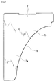
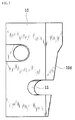
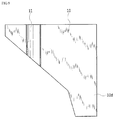
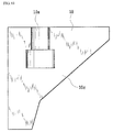
- the wedge member 10 has a wedge shape as a whole and has an outer contour of a substantially hexahedron shape.
- the wedge member 10 further includes: a screw engagement part 10a for attaching the wedge member 10; and a groove 11.
- the wedge member 10 includes: a front contact surface 10c that can be brought into contact with the rear wall surface 3h of the supporting walls 3e defining the pocket 21; and a rear contact surface 10d that generally opposes the front contact surface 10c and that can be brought into contact with the upper surface 2a of the cutting insert 2.
- the groove 11 is provided in the rear contact surface 10c.
- the screw engagement part 10a is located closer to the front contact surface 10c with respect to the groove 11 and is formed so as to open to the front contact surface 10c.
- the front contact surface 10c and the rear contact surface 10d of the wedge member 10 are formed in a wedge shape in order to firmly fix the cutting insert in the tool rotating direction R within the pocket 21 and are formed so as not to be parallel to each other.
- the front contact surface 10c and the rear contact surface 10d of the wedge member 10 are tilted with respect to each other so as to be tapered toward the cutting edge 2d in the direction of the central axis A, when arranged in the pocket 21. Accordingly, the wedge member 10 is prevented from being shifted toward the cutting edge 2d within the pocket 21.
- the screw engagement part 10a is configured such that a head part 20a of the fastening screw 20, being the wedge attachment member, is accommodated therein and engaged therewith and the screw part 20b of the fastening screw 20 is projected toward the outer side of the wedge member 10.
- the fastening screw 20 is screwed into the threaded hole 3k of the pocket 21 (see Fig. 19 ).
- the fastening screw 20 in the screw engagement part 10a is accessed by inserting a wrench or a screwdriver into an access hole 10b formed in the wedge member 10.
- the wrench or screwdriver is engaged with an engagement recess in the head part 20a of the fastening screw 20.
- the access hole 10b has a size that does not allow the head part 20a of the fastening screw 20 to pass therethrough.
- the groove 11 in the wedge member 10 is a groove for allowing the wrench or screwdriver for rotating the screw member 40 for the adjustment member 30 to pass therethrough.
- the groove 11 extends on an extension of the axis of rotation (the central axis 40c) of the screw member 40, thereby providing a workspace.
- the groove 11 is formed in a size that allows the wrench or screwdriver to move in and out and has, for example, a cross-sectional area larger than that of the shaft of such wrench or screwdriver.
- the groove 11 may be a through hole.
- the wedge member 10 may be divided into a plurality of members. If the wedge member 10 is constituted by a plurality of members, a workspace for the screw member 40 may be secured by arranging those members constituting the wedge member 10 so as not to cover or block the extension of the axis of rotation of the screw member 40.
- the wedge attachment member 20 it is preferable for the wedge attachment member 20 to also be constituted by a plurality of members, although the configuration is not limited thereto. If the plurality of members of the wedge member 10 can be attached in an integrated manner, the wedge attachment member 20 may be a single member.
- the wedge attachment member 20 may be constituted by a smaller number of members than the number of components of the wedge member 10.
- the width of the groove 11 of the rotary cutting tool 1 is about 8 mm.
- the width of the groove 11 is not limited thereto.
- the wedge member 10 may have any shape or may be divided in any way, as long as the wedge member 10 can exert its wedge action and the wedge member 10 can allow the wrench or screwdriver for rotating the screw member 40 to pass therethrough so as to be workable.
- the locator 50 in Fig. 15 is attached to the pocket 21 of the tool body 3 of the rotary cutting tool 1.
- the locator 50 is arranged on the rear side of the cutting insert 2 in the tool rotating direction R (i.e., the circumferential direction) of the tool body 3 and between the front wall surface 3i that defines the pocket 21 and the lower surface 2b of the cutting insert 2.
- the locator 50 includes: screw engagement parts (contact parts) 50a, 50b for attaching the locator 50 to the pocket 21 using screws; and threaded holes 50c and 50d for attaching the second adjustment member 60, which will be described later.
- the screw members 53, 54 engage with the screw engagement parts 50a, 50b, respectively, as shown in Figs. 18 and 19 .
- the locator 50 has a plate shape and includes two opposing end surfaces 50e, 50f and a peripheral side surface 50g extending therebetween.
- the locator 50 has a shape similar to the shape of the cutting insert 2.
- the locator 50 is designed so as to substantially determine the initial setting position of the cutting insert 2 such that, when the cutting insert 2 is arranged as shown in Fig. 1 , the cutting edge 2d of the cutting insert 2 is projected outward with respect to the locator 50 by a predetermined distance in the radial direction and in the direction of the axis of rotation A of the tool body 3.
- One end surface 50e of the two end surfaces of the locator 50 is configured as a contact surface to be brought into contact with the lower surface 2b (opposing the upper surface 2a serving as a cutting face) of the cutting insert 2.
- the locator 50 has, on its end surface 50e, a serration 51, corresponding to the serration 31 of the adjustment member 30.
- the serration 51 is formed in a serration shape so as to be engaged with the serration 31 of the adjustment member 30 and the serration 51 has an engagement part.
- the serration 51 may be configured as various types of recesses and projections or as a combination thereof, it is preferable to have a serration shape.
- the shape of the serration 51 is not limited thereto.
- the serration 51 of the locator 50 may have any shape, as long as it can correspond to the serration 31 of the adjustment member 30, define the direction of advancement and retraction of the adjustment member 30, and prevent the adjustment member 30 from being tilted.
- the end surface 50f of the locator 50 is configured as a contact surface to be brought into contact with the front wall surface e3i of the pocket 21.
- the screw engagement parts 50a, 50b are formed as stepped holes that penetrate the two end surfaces 50e, 50f, respectively.
- the threaded holes 50c and 50d are each formed in the peripheral side surface 50g and extend substantially in parallel to the two end surfaces 50e, 50f that are parallel to each other.
- the serration 51 is formed on a projected portion that is formed so as to be projected outward as a whole from the end surface 50e in the opposing direction of the end surfaces 50e, 50f.
- the cutting insert 2 may be mounted on the projected portion of the locator 50 and on the adjustment member 30, mainly on the adjustment member 30 in this example, within the pocket 21.
- the locator 50 is attached to the tool body 3 by screwing the screw members 53, 54 into the threaded holes in the pocket 21 via holes in the locator 50 , and the locator 50 serves as a part of the tool body 3.
- the locator 50 may not be used and the cutting insert 2 and the adjust member 30 may be directly brought into contact with the front wall surface 3i of the tool body 3.
- the use of the locator 50 can facilitate the formation of an engagement part, such as the serration 51, with a high level of accuracy.
- the engagement parts 50a, 50b of the locator 50 are not limited to stepped through holes and may employ various known shapes, such as grooves and recesses.
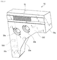
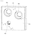
- the insert attachment mechanism 100 further includes a second adjustment member 60.
- the second adjustment member 60 includes a body part 60d having a flat plate-like shape.
- the second adjustment member 60 further includes an adjustment screw 61 for adjusting the position of the cutting edge 2d and, for this reason, the second adjustment member 60 has, in its body part 60d, a threaded hole 60a that allows such adjustment screw 61 to be screwed thereinto.
- the second adjustment member 60 is attached such that a central axis of the adjustment screw 61, being a second screw member, is substantially parallel to the central axis A and such that the adjustment screw 61 can act on the cutting insert 2.
- the body part 60d of the second adjustment member 60 is attached to the tool body 3 (in this example, the locator 50) by screwing the attachment screws (see Fig. 1 ) into the threaded holes 50c, 50d of the locator 50 attached to the tool body 3 and fastening the attachment screws. Accordingly, the second adjustment member 60 has, in its body part 60d, engagement parts (contact parts) 60b, 60c for the attachment using the adjustment screws.
- the engagement parts 60b, 60c of the second adjustment member 60 are stepped through holes similar to the engagement parts 50a, 50b of the locator 50, they may employ various known shapes, such as grooves and recesses.
- the method of adjusting the position of the cutting edge using the second adjust member 60 is not limited to the method using the adjustment screw 61.
- the adjustment method using the adjustment screw 61 as in the present embodiment is a simple method and is therefore favorable, as will be described later. It should be noted that, in Fig. 16 , the inner surface of the threaded hole 60a of the second adjustment member 60 is provided with a screw thread.
- Materials used for the cutting edge 2d of the cutting inset 2 and its peripheral area may be selected from a cemented carbide, cermet, ceramic, rigid materials such as cubic boron nitride, such rigid materials coated with a PVD coating film or CVD coating film, or diamond.
- Materials for the parts other than the cutting edge are preferably similar materials, such as rigid materials.
- the locator 50 is attached to the pocket 21.
- the locator 50 at this point in time may have the second adjustment member 60 attached thereto.
- the adjustment member 30 is then located.
- the adjustment member 30 is arranged such that the threaded hole 30b is located in the recessed part 3g of the pocket 21 and the serration 31 is engaged with the serration 51 of the locator 50.
- the adjustment member 30 can substantially move only in a predetermined direction, being a substantially radial direction of the tool body 3 (the direction of the central axis 40c of the screw member 40) in accordance with the engagement between the serrations 31, 51 and can be brought into contact with, for example, the bottom wall surface 3j of the pocket 21.
- the screw member 40 having the above configuration is screwed into the threaded hole 30c of the adjustment member 30 and the threaded hole 3m of the pocket 21.
- the wedge member 10 is arranged on the radially outer side of the threaded hole 30b of the adjustment member 30.
- the cutting insert 2 is arranged on the radially outer side of the body part 30a of the adjustment member 30 in the pocket 21 (i.e., on the outer side of the body part 30a in the radial direction of the tool body 3) such that the upper surface 2a of the cutting insert 2 faces in the tool rotating direction R.
- the cutting insert 2 is inserted into the space on the rear side of the wedge member 10 in the tool rotating direction and on the front side of the locator 50 in the tool rotating direction until the cutting insert 2 comes into contact with the adjustment member 30.
- the wedge member 10 may be arranged on the radially outer side of the threaded hole 30b of the adjustment member 30 after the cutting insert 2 is arranged.
- the cutting insert 2 By firmly fastening the fastening screw 20 with the various members being arranged around the cutting insert 2, the cutting insert 2 can be firmly attached to the pocket 21 due to the wedge action of the wedge member 10. At this time, the fastening screw 20 is fastened while the cutting insert 10 is being pressed against the locator 50, the adjustment member 30 and the second adjustment member 60, and the position of the cutting edge 2d is thereby determined by the relative positional relationship between these members.
- the cutting insert 2 moves radially inward following the movement of the adjustment member 30, and the position of the cutting edge 2d of the cutting insert 2 can be changed.
- the wedge member 10 is firmly fixed in the pocket 21 and the attachment of the cutting insert 2 is thereby completed. In this way, the position of the cutting edge 2d of the cutting insert 2 can be easily adjusted with the wedge member 10 and the cutting insert 2 being arranged.
- the adjustment screw 61 of the second adjustment member 60 is rotated by, for example, a screwdriver, with the wedge member 10 being loosened.
- the cutting edge 2d of the cutting insert 2 is moved, for example, outward in the direction of the central axis A, by rotating the adjustment screw 61 around the central axis so as to further screw the adjustment screw 61 into the threaded hole 60a, the cutting insert 2 is moved, from the state shown in Fig. 20A , as shown by an arrow in Fig. 20B .
- the screw member 40 for attaching and moving the adjustment member 30 is accessible from the radially outer side of the wedge member 10 in the state in which the wedge member 10 is arranged. Accordingly, the position (particularly the position in the radial direction) of the adjustment member 30 can be adjusted while the wedge member 10 and the cutting insert 2 are being arranged and the position of the cutting edge 2d of the cutting insert 2 can be adjusted easily and rapidly.
- the position adjustment of the cutting edge 2d is performed by moving the screw member 40, the amount of position adjustment of the cutting edge can be set arbitrarily. Accordingly, when, for example, the cutting edge is sharpened, the position of the cutting edge can be adjusted more appropriately.
- the position of the cutting edge 2d can be adjusted using the second adjustment member 60. Since the position adjustment of the cutting edge by the adjustment screw 61 of such second adjustment member 60 is also a position adjustment using the screw mechanism, the amount of position adjustment of the cutting edge can be set arbitrarily.
- the insert attachment mechanism may be changed so that the position adjustment direction of the cutting edge by the adjustment member 30 intersects with, but is not orthogonal to, the position adjustment direction of the cutting edge by the second adjustment member 60.
- the present invention is not limited to the embodiments described above but encompasses various other embodiments. Various modifications and additions may be made to the above embodiments without departing from the gist of the present invention.
- the shape of the groove to be formed by the cutting tool according to the present invention is not limited to a tooth form of a gear.
- the present invention is also applicable to a rotary cutting tool that uses a wedge member for attaching a cutting insert, such as a face milling cutter, without being limited to the side cutter.
Landscapes
- Engineering & Computer Science (AREA)
- Mechanical Engineering (AREA)
- Milling Processes (AREA)
- Details Of Cutting Devices (AREA)
Abstract
Description
- The present invention relates to: an insert attachment mechanism for attaching a cutting insert to a tool body; and a cutting tool to which this insert attachment mechanism is applied. In particular, the present invention relates to a rotary cutting tool detachably fitted with a cutting insert and used for cutting metallic materials and the like.
-
Patent Document 1 discloses an example of a conventional rotary cutting tool. A rotary cutting tool that is detachably fitted with a cutting insert inPatent Document 1 employs a wedge member in order to attach the cutting insert in an insert attachment groove in a tool body. The cutting insert is arranged on the radially outer side with respect to the axis of rotation of the tool body. The wedge member is located at a front part of the cutting insert in a tool rotating direction. By fastening a right-and-left screw that is screwed into a threaded hole in the wedge member and a threaded hole in a groove bottom of the insert attachment groove, the wedge member presses a surface of the cutting insert which faces forward in the tool rotating direction and a wedge-contacting surface of the insert attachment groove which faces backward in the tool rotating direction. As a result, the cutting insert is attached to the insert attachment groove of the tool body. - The cutting tool in
Patent Document 1 further includes a support member for adjusting the position of a cutting edge in the cutting tool when the cutting edge of the cutting insert is subjected to resharpening. The support member is located on the radially inner side of the cutting insert. The cutting insert is attached so as to be in contact with a contacting surface of the support member which faces radially outward. The support member is inserted into a groove of the tool body in the direction of the above-mentioned axis of rotation (i.e., a direction orthogonal to the radial direction) in such a manner that the support member is engaged with an engagement part of the groove. The position to insert the support member into the groove is selected so as to adjust the cutting edge to be located at a desired position and such position can be varied at a constant pitch in the radial direction. - Patent-Document 1:
JP2004-261899 A - In the cutting tool disclosed in
Patent Document 1, although the radial position of the cutting edge can be adjusted in a constant pitch in the radial direction, the position adjustment of the cutting edge can be carried out only in that pitch. In other words, the position adjustment mechanism for the cutting edge inPatent Document 1 is not capable of carrying out the position adjustment of the cutting edge by an arbitrary adjustment amount. - One known method to enable the position adjustment of the cutting edge by an arbitrary adjustment amount, is a method using a screw member. When a screw member is used to adjust the position of the cutting edge by an arbitrary adjustment amount, a position adjustment of the cutting edge in the direction of the axis of rotation of the screw member can be achieved by a simple structure. However, when the cutting insert is attached using the wedge member as disclosed in
Patent Document 1, the cutting insert exists in the adjustment direction of the position of the cutting insert. Accordingly, the cutting insert or both the cutting insert and the wedge member will be an obstacle, causing a problem of inconvenience in which the screw member cannot be rotated by a wrench or the like unless the cutting insert or both the cutting insert and the wedge member are detached. - The present invention has been made in light of such circumstances and an object of the present invention is to enable the position adjustment of a cutting edge of a cutting insert by an arbitrary adjustment amount more easily while using a wedge member for attaching the cutting insert to a tool body.
- An aspect of the present invention provides an insert attachment mechanism for detachably attaching a cutting insert to an insert attachment part of a tool body, the insert attachment mechanism comprising: an adjustment member arranged on an inner side of the cutting insert in the insert attachment part to act on the cutting insert, in which a screw member is screwed into at least one threaded hole formed in at least one of the adjustment member and the insert attachment part, the adjustment member being advanceable and retractable in a direction of a central axis of the screw member by rotating the screw member; and a wedge member arranged together with the cutting insert on an outer side of the adjustment member in the insert attachment part, the wedge member being attached so as to exert a pressing force against the cutting insert and an inner wall surface of the insert attachment part by a wedge attachment member, wherein the wedge member is configured such that the screw member is accessible from an outer side of the wedge member.
- The insert attachment mechanism having the above configuration according to an aspect of the present invention enables the cutting insert to be firmly attached to the insert attachment part by the wedge action of the wedge member and further enables the position of the cutting edge of the cutting insert to be adjusted by an arbitrary adjustment amount by adjusting the position of the adjustment member using the screw member. In addition, since the wedge member is configured such that the screw member is accessible from the outer side of the wedge member, the screw member can be rotated without detaching the cutting insert and the wedge member. Thus, according to an aspect of the present invention, it is possible to carry out fine adjustment of the position of the cutting edge of the cutting insert more easily in a state in which the cutting insert and the wedge member are arranged in the insert attachment part.
- The wedge member preferably has a groove or a through hole for allowing access to the screw member.
- The screw member preferably includes two screw parts having different winding directions. In this case, one of the two screw parts may be screwed into the threaded hole formed in the adjustment member and the other one of the screw parts may be screwed into the threaded hole formed in the insert attachment part.
- The adjustment member preferably has an engagement part that is engageable with an engagement part provided on the insert attachment part so as to guide a movement of the adjustment member in a direction of the central axis of the screw member.
- The engagement part of the adjustment member preferably has a serration shape. The serration shape may have a plurality of projections and recesses. Such engagement part may have various types of engaging shapes having at least one projection or recess.
- The insert attachment mechanism preferably further comprises a locator to be arranged in the insert attachment part. In this case, the engagement part of the insert attachment part may be formed in the locator.
- The insert attachment mechanism preferably further comprises a second adjustment member for moving the cutting insert in a second direction intersecting with (for example, substantially orthogonal to) a moving direction of the adjustment member associated with a rotation of the screw member. In this case, the second adjustment member may comprise a second screw member that is advanceable and retractable in the second direction.
- The present invention also resides in a tool body comprising the insert attachment part of the above-mentioned insert attachment mechanism.
- The present invention also resides in a wedge member of the above-mentioned insert attachment mechanism.
- The present invention also resides in an adjustment member of the above-mentioned insert attachment mechanism.
- The present invention also resides in a cutting tool in which a cutting insert is detachably attached to a tool body, to which the above-mentioned insert attachment mechanism is applied. Such cutting tool may be a rotary cutting tool rotated around an axis of rotation. When the insert attachment mechanism comprises the above-mentioned second adjustment member, the second direction of the second screw member may be a direction substantially parallel to the axis of rotation of the rotary cutting tool.
-
-
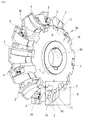
Fig. 1 is a perspective view showing a cutting tool according to an embodiment of the present invention. -
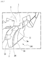
Fig. 2 is an enlarged view showing an area II ofFig. 1 in the cutting tool ofFig. 1 . -
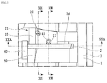
Fig. 3 is an enlarged view showing an area III ofFig. 17 in the cutting tool ofFig. 1 . -
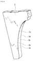
Fig. 4 is a perspective view showing a cutting insert in the cutting tool ofFig. 1 . -
Fig. 5 is a plan view showing the cutting insert ofFig. 4 . -
Fig. 6 is a perspective view showing a wedge member in the cutting tool ofFig. 1 . -
Fig. 7 is a plan view showing the wedge member ofFig. 6 . -
Fig. 8 is a front view showing the wedge member ofFig. 6 . -
Fig. 9 is a right side view showing the wedge member ofFig. 6 . -
Fig. 10 is a left side view showing the wedge member ofFig. 6 . -
Fig. 11 is a rear view showing the wedge member ofFig. 6 . -
Fig. 12 is a bottom view showing the wedge member ofFig. 6 . -
Fig. 13 is a perspective view showing an adjustment member in the cutting tool ofFig. 1 . -
Fig. 14 is a plan view showing the adjustment member ofFig. 13 . -
Fig. 15 is a perspective view showing a locator in the cutting tool ofFig. 1 . -
Fig. 16 is a perspective view showing a second adjustment member from which a screw member has been removed, in the cutting tool ofFig. 1 . -
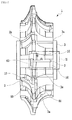
Fig. 17 is a plan view showing the cutting tool ofFig. 1 . -
Fig. 18 is a partial cross-sectional view taken along line XVIII-XVIII inFig. 3 in the cutting tool ofFig. 1 . -
Fig. 19 is a partial cross-sectional view taken along line XIX-XIX inFig. 3 in the cutting tool ofFig. 1 . -
Fig. 20A is a schematic and partial cross-sectional view taken along line XXA-XXA inFig. 3 in the cutting tool ofFig. 1 . -
Fig. 20B is a schematic and partial cross-sectional view showing a state in which the position of the cutting insert has been shifted from the state shown inFig. 20A . -
Fig. 21 is a perspective view showing a tool body of the cutting tool inFig. 1 . - A
cutting tool 1 according to an embodiment of the present invention will now be described with reference to the attached drawings. - As shown in
Fig. 1 , arotary cutting tool 1 in this embodiment is a side cutter provided with a substantiallydiscoid tool body 3, more specifically, a gear cutter. Thetool body 3 has a substantially discoid shape having two opposingend surfaces peripheral part 3c extending between these two end surfaces. Thetool body 3 is provided with a throughhole 3d so as to penetrate the twoend surfaces hole 3d, thetool body 3 is attached to the main shaft or the like of the arbor or the machining tool. Therotary cutting tool 1 having thetool body 3 is rotated with the central axis A of the throughhole 3d serving as an axis of rotation. Theperipheral part 3c is provided with a plurality ofinsert attachment parts 21. A cuttinginsert 2 is attached to eachinsert attachment part 21. - The cutting
inset 2 has a plate-like shape as shown inFigs. 4 and5 and has twoopposing end surfaces peripheral side surface 2c extending between the two end surfaces. The cuttinginsert 2 includes acutting edge 2d that extends at an intersection between oneend surface 2a and theperipheral side surface 2d. Thecutting edge 2d is formed so as to be capable of cutting a groove having a curved cross-sectional shape. In particular, since the cuttinginsert 2 is formed so as to be usable in gear cutting, thecutting edge 2d has a tooth-form curved shape (for example, an involute curved shape). Accordingly, thecutting tool 1 to which thecutting insert 2 has been attached serves as a so-called formed tool, as is obvious from the above description. - The cutting
insert 2 includes a right-hand cutting insert 2 and a left-hand cutting insert 2. The right-hand cutting insert 2 and the left-hand cutting insert 2 are arranged alternately on theperipheral part 3c of thetool body 3 so as to form a staggered arrangement. With six cuttinginserts 2 being arranged on theend surface 3a of thetool body 3 and six cuttinginserts 2 being arranged on theend surface 3b, twelve cuttinginserts 2 in total are arranged on thetool body 3. Thus, from among the twoend surfaces end surface 3a are right-hand cutting inserts and the cutting inserts located on theother end surface 3b are left-hand cutting inserts 2. The cutting inserts shown inFigs. 4 and5 are right-hand cutting inserts 2. Since the left-hand cutting inserts 2 have a shape that is reflection-symmetric to the right-hand cutting inserts 2, the explanation thereof will be omitted. - In the plan view of
Fig. 5 , the curved edge line formed on the lower right part of the cuttinginsert 2 is thecutting edge 2d. Theend surface 2a having thecutting edge 2d on its edge serves as a cutting face which is referred to herein as an upper surface. A side surface (acurved side surface 2e) in theperipheral side surface 2c having thecutting edge 2d on its edge serves as a flank. However, thecutting edge 2d may extend to a part other than the curved edge line and a portion other than thecurved side surface 2e in theperipheral side surface 2c may also serve as the flank. It should be noted that the shape of the cutting edge and the number and arrangement of the cutting inserts 2 to be attached to the tool body are not limited to those indicated in the present embodiment and they may be adjusted as appropriate, depending on the shape of a work piece and the cutting condition. - The
cutting tool 1 has aninsert attachment mechanism 100 for allowing the cuttinginsert 2 to be fixed to or attached to (i.e., mounted on) thetool body 3 thereof (i.e., theinsert attachment mechanism 100 is applied to the cutting tool 1). Theinsert attachment mechanism 100 includes awedge member 10, anadjustment member 30, a locator (position adjustment member) 50 and asecond adjustment member 60 and each of these components are detachably attached to aninsert attachment part 21. - The
rotary cutting tool 1 to which the cutting inserts 2 are firmly attached by theinsert attachment mechanism 100 is shown inFigs. 1 and17 . InFig. 17 , thecutting tool 1 is shown such that the central axis A (not shown inFig. 17 ) of the throughhole 3d which serves as the axis of rotation of therotary cutting tool 1 is parallel to the plane of the page. Accordingly, the cross-sectional views inFigs. 18 and19 are partial cross-sectional views each showing therotary cutting tool 1 in a plane orthogonal to the central axis A.Figs. 20A and20B are partial cross-sectional view each schematically showing therotary cutting tool 1 in the plane parallel to the central axis A. In the following description, theinsert attachment mechanism 100 will be described in detail based on these assembly drawings and cross-sectional views. First, theinsert attachment part 21 of thetool body 3, to which theinsert attachment mechanism 100 is applied, will be described. - The
tool body 3 has a plurality of supportingwalls 3e on its peripheral part (or circumferential surface) 3c. Each supportingwall 3e extends so as to be projected generally radially with respect to the central axis A. The supportingwalls 3e are arranged at an equal interval in the circumferential direction around the central axis A of the throughhole 3d. In thecutting tool 1, the number of supportingwalls 3e is the same as the number of cutting inserts 2 to be attached to thetool body 3. Accordingly, thetool body 3 has twelve supportingwalls 3e in this embodiment. However, the number of supportingwalls 3e may not be the same as the number of the cutting inserts 2 to be attached to thetool body 3. - Two supporting
walls 3e that are adjacent to each other in the circumferential direction define aninsert attachment part 21 therebetween. In other words, by focusing on two adjacent supportingwalls 30e and terming one of them as a first supporting wall 3e1 and the other one as a second supporting wall 3e2 (see the supporting walls in the lower part ofFig. 21 ), theinsert attachment part 21 is defined generally by: arear wall surface 3h, which faces backward in a rotating direction R around the central axis A, of the first supporting wall 3e1 located on the front side in the rotating direction R; a front wall surface 3i, which faces forward in the rotating direction R around the central axis A, of the second support wall 3e2 located on the rear side in the rotating direction R; and a bottom wall surface 3j extending between thesewall surfaces 3h and 3i. As described above, theinsert attachment part 21 having, as its inner wall surfaces, the threewall surfaces 3h, 3i, 3j, has a groove-like or a pocket-like shape and suchinsert attachment part 21 will therefore be referred to as a pocket in some contexts in the following description. Thepocket 21 is formed such that its spatial area is expanded radially outward. This is mainly because theinsert attachment mechanism 100 employs thewedge member 10 in order to firmly attach thecutting insert 2. It should be noted that, although eachinsert attachment part 21 is opened in the direction of the central axis A, theinsert attachment part 21 may have one or more walls for supporting the cuttinginsert 2 in the direction of the central axis A. Thepocket 21 to which the right-hand cutting insert 2 is to be attached and thepocket 21 to which the left-hand cutting insert 2 is to be attached have, in general, a bilaterally symmetric relationship (with respect to a virtual plane (not shown) orthogonal to the central axis A of the throughhole 3d and passing through theperipheral part 3c). - Each
pocket 21 includes: a steppedpart 3f based on the positional relationship between thewedge portion 10 and the adjustment member 30 (which will be described in detail later); a recessedpart 3g formed in the stepped part 3s so as to be adapted to the shape of theadjustment member 30; and a plurality of threaded holes to be engaged with screw members which will be described later. The steppedpart 3f is formed so as to extend in the direction of the central axis A in an intersection space between therear wall surface 3h and the bottom wall surface 3j. The recessedpart 3g is formed by cutting out the steppedpart 3f toward the bottom wall surface 3j side. In this way, the steppedpart 3f and the recessedpart 3g are provided in therear wall surface 3h of the first supporting wall 3e1, which is located on the front side in the rotating direction R around the central axis A, from among the first and second supporting walls. - As can be seen from
Figs. 1-3 , the cuttinginsert 2 of therotary cutting tool 1 is attached using thewedge member 10. Thewedge member 10 is shown inFigs. 6-12 and is designed to fix thecutting insert 2 in thepocket 21 with its wedge action. As shown inFig. 3 , thewedge member 10 is fixed or attached to thepocket 21 using awedge attachment member 20. Thewedge attachment member 20 is a fastening screw. Thewedge member 10 is arranged in thepocket 21. In therotary cutting tool 1, a threadedhole 3k is provided in thepocket 21. In particular, the threadedhole 3k is provided in the steppedpart 3f and extends in a direction intersecting with the bottom wall surface 3j (seeFig. 21 ). Thefastening screw 20 is screwed into the threadedhole 3k and is advanceable and retractable within thepocket 21 in the direction of its central axis in accordance with its rotation around the central axis. By fastening thefastening screw 20 so as to move toward the deepest part of thepocket 21 or to move radially inward, thewedge member 10 is pressed into the deeper side or inner side of thepocket 21. By pressing thewedge member 10 in between therear wall surface 3h of thepocket 21 and anupper surface 2a of the cuttinginsert 2 serving as a contact surface facing forward in the rotating direction R of the tool so as to apply a pressing force thereto, the cuttinginsert 2 is firmly fixed to thetool body 3. When thewedge member 10 is loosened to detach thecutting insert 2, thefastening screw 20 is loosened so as to move radially outward of thepocket 21. The advancing and retracting direction of thewedge member 10 is a direction substantially parallel to the advancing and retracting direction of thefastening screw 20. In thisrotary cutting tool 1, as is obvious fromFig. 19 , the advancing and retracting direction of thefastening screw 20 is a direction tilted with respect to theupper surface 2a of the cuttinginsert 2. In particular, the tilt direction of the fastening screw 20 (i.e., the tilt direction of the central axis of the threadedhole 3k) is defined such that thefastening screw 20 is moved further away from thetop surface 2a of the cuttinginsert 2 as it is retracted radially outward and the tilt direction is defined along a virtual plane (Fig. 19 ) which is orthogonal to the central axis A. In this way, by configuring the advancing and retracting direction of thefastening screw 20 so as to be tilted with respect to theupper surface 2a of the cuttinginsert 2, thewedge member 10 can be easily released from the cuttinginsert 2 when thefastening screw 20 is loosened. It should be noted that the shape of thewedge member 10 shown inFigs. 6-12 will be described later and its explanation is therefore omitted here. -
Figs. 13 and14 show theadjustment member 30. Theadjustment member 30 is a member that comes into contact with (acts on) thecutting insert 2 in order to adjust the position of the cutting edge of the cuttinginsert 2. Theadjustment member 30 includes a substantially rectangularparallelepiped body part 30a, a threadedhole part 30b provided substantially at the central position in the longitudinal direction of thebody part 30a, and aserration 31 serving as an engagement part having a positional relationship so as to oppose the threadedhole part 30b. - The
body part 30a has four surfaces that extend in the longitudinal direction and two relatively small surfaces that extend between these four surfaces. The threadedhole part 30b and theserration 31 are formed in two opposing surfaces from among the four surfaces of thebody part 30a which extend in the longitudinal direction. Theserration 31 is formed on asurface 30e that opposes asurface 30d in which the threadedhole part 30b is formed so as to be projected. Here, a first virtual plane S1 that extends in the longitudinal direction of thebody part 30a and substantially divides thebody part 30a into halves is defined as shown inFig. 14 . The first virtual plane S1 extends substantially in parallel to the twosurfaces hole part 30b is formed so as to be projected from thebody part 30a toward one side (thesurface 30d side) of the first virtual plane S1 and located substantially at the opposite side of theserration 31 with respect to the first virtual plane S1. If a second virtual plane S2 were to be defined so as to be orthogonal to the first virtual plane S1 and so as to divide thebody part 30a into halves, such second virtual plane S2 would extend so as to contain acentral axis 30f of the threadedhole 30c of the threadedhole part 30b. The surfaces other than the two opposingsurfaces 30e (on which theserration 31 is formed) and 30d (on which the threadedhole part 30b is formed so as to be projected) are formed as flat surfaces. In particular, asurface 30g that is shown so as to be parallel to the plane of the page showingFig. 14 and that serves as a contacting surface of theadjustment member 30 to be brought into contact with the cuttinginsert 2 is shown as a flat surface, but it may not necessarily be flat. It should be noted the shape of the threadedhole part 30b projected from thebody part 30a is designed so that the threadedhole part 30b fits into the recessedpart 3g of thepocket 21. - The
serration 31 has a plurality of projections and recesses and more specifically has a serration shape (serrated shape). Although theserration 31 may only have one projection or one recess, it has a plurality of projections and recesses. The recesses (groves) and projections (ridges) of theserration 31 extend substantially in parallel to the second virtual plane S2 and substantially in parallel to thecentral axis 30f of the threadedhole 30c. The projections and recesses of theserration 31 define the advancing and retracting direction of theadjustment member 30 within thepocket 21. Accordingly, theserration 31 engages with a serration, serving as an engagement part, of thelocator 50, which will be described later, and functions as a guide for theadjustment member 30. Theserration 31 may have any shape as long as it can prevent theadjustment member 30 from being tilted in the pocket 21 (i.e., any shape capable of firmly guiding theadjustment member 30 may be employed). - A
screw member 40 is screwed into the threadedhole 30c of theadjustment member 30. The threadedhole 30c has a screw thread in its inner surface. Thescrew member 40 is also brought into contact with thepocket 21. Specifically, thescrew member 40 is formed so as to also be screwed into the threadedhole 3m formed in thepocket 21. The threadedhole 3m is located in the recessedpart 3g and extends so as to be crossed with, in particular, so as to form a right angle with respect to, the bottom wall surface 3j. Theadjustment member 30 is configured to be advanceable and retractable with respect to thepocket 21 in the central axis direction of the screw member 40 (i.e., the central axis direction of the threadedhole 3m). Thescrew member 40 of therotary cutting tool 1 is configured as a so-called right-and-left screw that includes twoscrew parts Fig. 18 , the two screw parts of thescrew member 40 are arranged in line in the direction of anaxis 40c of thescrew member 40 with one (40a) of the two screw parts being screwed into the threadedhole 30c of theadjustment member 30 and the other one (40b) of the screw parts being screwed into the threadedhole 3m of thepocket 21. Since the winding directions of the two screw parts of thescrew member 40 are different from each other, by rotating thescrew member 40 around itscentral axis 40c thereof in a state in which it is being engaged with theadjustment member 30 and thepocket 21, theadjustment member 30 becomes advanceable and retractable in the direction of thecentral axis 40c of thescrew member 40 in thepocket 21. Since thecentral axis 40c of the screw member 40 (i.e., the central axis of the threadedhole 3m) is parallel to the plane of the page showingFig. 18 , the advancement and retraction of thescrew member 40 due to the engagement with thescrew hole 3m is generated along a virtual plane orthogonal to the central axis A of the throughhole 3d. The distance of advancement and retraction of thescrew member 40 can be freely set with respect to the rotational angle of the screw around thecentral axis 40c and can be set, for example, to be relatively large. Thus, even in a situation in which a space for rotating a wrench engaging the engaging part on one end (an end on thescrew part 40a side in the direction of thecentral axis 40c) of thescrew member 40 is small, the positional adjustment of theadjustment member 30 can still be performed easily. The total length of the adjustment member 30 (the length along the first virtual plane) of suchrotary cutting tool 1 is about 70 mm. The thickness of the adjustment member 30 (the maximum length in the threadedhole part 30 along the second virtual plane) is about 15 mm. However, the size of theadjustment member 30 is not limited to such length and thickness. - As can be seen in
Figs. 6-12 , thewedge member 10 has a wedge shape as a whole and has an outer contour of a substantially hexahedron shape. Thewedge member 10 further includes: ascrew engagement part 10a for attaching thewedge member 10; and agroove 11. Thewedge member 10 includes: afront contact surface 10c that can be brought into contact with therear wall surface 3h of the supportingwalls 3e defining thepocket 21; and arear contact surface 10d that generally opposes thefront contact surface 10c and that can be brought into contact with theupper surface 2a of the cuttinginsert 2. Thegroove 11 is provided in therear contact surface 10c. Thescrew engagement part 10a is located closer to thefront contact surface 10c with respect to thegroove 11 and is formed so as to open to thefront contact surface 10c. - The
front contact surface 10c and therear contact surface 10d of thewedge member 10 are formed in a wedge shape in order to firmly fix the cutting insert in the tool rotating direction R within thepocket 21 and are formed so as not to be parallel to each other. In addition, as shown inFig. 3 , thefront contact surface 10c and therear contact surface 10d of thewedge member 10 are tilted with respect to each other so as to be tapered toward thecutting edge 2d in the direction of the central axis A, when arranged in thepocket 21. Accordingly, thewedge member 10 is prevented from being shifted toward thecutting edge 2d within thepocket 21. - As shown in
Fig. 6 , thescrew engagement part 10a is configured such that ahead part 20a of thefastening screw 20, being the wedge attachment member, is accommodated therein and engaged therewith and thescrew part 20b of thefastening screw 20 is projected toward the outer side of thewedge member 10. Thefastening screw 20 is screwed into the threadedhole 3k of the pocket 21 (seeFig. 19 ). Thefastening screw 20 in thescrew engagement part 10a is accessed by inserting a wrench or a screwdriver into anaccess hole 10b formed in thewedge member 10. The wrench or screwdriver is engaged with an engagement recess in thehead part 20a of thefastening screw 20. It should be noted that theaccess hole 10b has a size that does not allow thehead part 20a of thefastening screw 20 to pass therethrough. - The
groove 11 in thewedge member 10 is a groove for allowing the wrench or screwdriver for rotating thescrew member 40 for theadjustment member 30 to pass therethrough. Thus, as will be described later, when theadjustment member 30 is arranged on a radially inner side (or the deeper side) of thepocket 21 and thewedge member 10 is arranged on the radially outer side thereof, thegroove 11 extends on an extension of the axis of rotation (thecentral axis 40c) of thescrew member 40, thereby providing a workspace. Thegroove 11 is formed in a size that allows the wrench or screwdriver to move in and out and has, for example, a cross-sectional area larger than that of the shaft of such wrench or screwdriver. - The
groove 11 may be a through hole. Thewedge member 10 may be divided into a plurality of members. If thewedge member 10 is constituted by a plurality of members, a workspace for thescrew member 40 may be secured by arranging those members constituting thewedge member 10 so as not to cover or block the extension of the axis of rotation of thescrew member 40. When thewedge member 10 is constituted by the plurality of members, it is preferable for thewedge attachment member 20 to also be constituted by a plurality of members, although the configuration is not limited thereto. If the plurality of members of thewedge member 10 can be attached in an integrated manner, thewedge attachment member 20 may be a single member. In other words, thewedge attachment member 20 may be constituted by a smaller number of members than the number of components of thewedge member 10. The width of thegroove 11 of therotary cutting tool 1 is about 8 mm. However, the width of thegroove 11 is not limited thereto. Thewedge member 10 may have any shape or may be divided in any way, as long as thewedge member 10 can exert its wedge action and thewedge member 10 can allow the wrench or screwdriver for rotating thescrew member 40 to pass therethrough so as to be workable. - As can be seen from
Figs. 1-3 , thelocator 50 inFig. 15 is attached to thepocket 21 of thetool body 3 of therotary cutting tool 1. Thelocator 50 is arranged on the rear side of the cuttinginsert 2 in the tool rotating direction R (i.e., the circumferential direction) of thetool body 3 and between the front wall surface 3i that defines thepocket 21 and thelower surface 2b of the cuttinginsert 2. Thelocator 50 includes: screw engagement parts (contact parts) 50a, 50b for attaching thelocator 50 to thepocket 21 using screws; and threadedholes second adjustment member 60, which will be described later. It should be noted that thescrew members screw engagement parts Figs. 18 and19 . - The
locator 50 has a plate shape and includes twoopposing end surfaces 50e, 50f and aperipheral side surface 50g extending therebetween. Thelocator 50 has a shape similar to the shape of the cuttinginsert 2. Thelocator 50 is designed so as to substantially determine the initial setting position of the cuttinginsert 2 such that, when the cuttinginsert 2 is arranged as shown inFig. 1 , thecutting edge 2d of the cuttinginsert 2 is projected outward with respect to thelocator 50 by a predetermined distance in the radial direction and in the direction of the axis of rotation A of thetool body 3. Oneend surface 50e of the two end surfaces of thelocator 50 is configured as a contact surface to be brought into contact with thelower surface 2b (opposing theupper surface 2a serving as a cutting face) of the cuttinginsert 2. Thelocator 50 has, on itsend surface 50e, aserration 51, corresponding to theserration 31 of theadjustment member 30. Theserration 51 is formed in a serration shape so as to be engaged with theserration 31 of theadjustment member 30 and theserration 51 has an engagement part. Although theserration 51 may be configured as various types of recesses and projections or as a combination thereof, it is preferable to have a serration shape. However, the shape of theserration 51 is not limited thereto. Theserration 51 of thelocator 50 may have any shape, as long as it can correspond to theserration 31 of theadjustment member 30, define the direction of advancement and retraction of theadjustment member 30, and prevent theadjustment member 30 from being tilted. The end surface 50f of thelocator 50 is configured as a contact surface to be brought into contact with the front wall surface e3i of thepocket 21. Thescrew engagement parts end surfaces 50e, 50f, respectively. The threadedholes peripheral side surface 50g and extend substantially in parallel to the twoend surfaces 50e, 50f that are parallel to each other. It should be noted that theserration 51 is formed on a projected portion that is formed so as to be projected outward as a whole from theend surface 50e in the opposing direction of the end surfaces 50e, 50f. As shown inFig. 19 , the cuttinginsert 2 may be mounted on the projected portion of thelocator 50 and on theadjustment member 30, mainly on theadjustment member 30 in this example, within thepocket 21. - As shown in
Figs. 18 and19 , thelocator 50 is attached to thetool body 3 by screwing thescrew members pocket 21 via holes in thelocator 50 , and thelocator 50 serves as a part of thetool body 3. Thelocator 50 may not be used and the cuttinginsert 2 and the adjustmember 30 may be directly brought into contact with the front wall surface 3i of thetool body 3. However, the use of thelocator 50 can facilitate the formation of an engagement part, such as theserration 51, with a high level of accuracy. Theengagement parts locator 50 are not limited to stepped through holes and may employ various known shapes, such as grooves and recesses. - As shown in
Figs. 1 ,3 and16 , theinsert attachment mechanism 100 further includes asecond adjustment member 60. Thesecond adjustment member 60 includes abody part 60d having a flat plate-like shape. Thesecond adjustment member 60 further includes anadjustment screw 61 for adjusting the position of thecutting edge 2d and, for this reason, thesecond adjustment member 60 has, in itsbody part 60d, a threadedhole 60a that allowssuch adjustment screw 61 to be screwed thereinto. By bringing theadjustment screw 61 into contact with the cuttinginsert 1 as needed, the position of thecutting edge 2d can be adjusted. Thesecond adjustment member 60 is attached such that a central axis of theadjustment screw 61, being a second screw member, is substantially parallel to the central axis A and such that theadjustment screw 61 can act on the cuttinginsert 2. Thebody part 60d of thesecond adjustment member 60 is attached to the tool body 3 (in this example, the locator 50) by screwing the attachment screws (seeFig. 1 ) into the threadedholes locator 50 attached to thetool body 3 and fastening the attachment screws. Accordingly, thesecond adjustment member 60 has, in itsbody part 60d, engagement parts (contact parts) 60b, 60c for the attachment using the adjustment screws. Although theengagement parts second adjustment member 60 are stepped through holes similar to theengagement parts locator 50, they may employ various known shapes, such as grooves and recesses. The method of adjusting the position of the cutting edge using the second adjustmember 60 is not limited to the method using theadjustment screw 61. However, the adjustment method using theadjustment screw 61 as in the present embodiment is a simple method and is therefore favorable, as will be described later. It should be noted that, inFig. 16 , the inner surface of the threadedhole 60a of thesecond adjustment member 60 is provided with a screw thread. - Materials used for the
cutting edge 2d of the cuttinginset 2 and its peripheral area may be selected from a cemented carbide, cermet, ceramic, rigid materials such as cubic boron nitride, such rigid materials coated with a PVD coating film or CVD coating film, or diamond. Materials for the parts other than the cutting edge are preferably similar materials, such as rigid materials. - An example procedure for attaching the cutting
insert 2 using the above-describedinsert attachment mechanism 100 will now be described below. However, the following description is not intended to exclude other sequences of operation. - First, the
locator 50 is attached to thepocket 21. Thelocator 50 at this point in time may have thesecond adjustment member 60 attached thereto. Theadjustment member 30 is then located. Theadjustment member 30 is arranged such that the threadedhole 30b is located in the recessedpart 3g of thepocket 21 and theserration 31 is engaged with theserration 51 of thelocator 50. As a result, theadjustment member 30 can substantially move only in a predetermined direction, being a substantially radial direction of the tool body 3 (the direction of thecentral axis 40c of the screw member 40) in accordance with the engagement between theserrations pocket 21. When theadjustment member 30 is arranged, thescrew member 40 having the above configuration is screwed into the threadedhole 30c of theadjustment member 30 and the threadedhole 3m of thepocket 21. Thewedge member 10 is arranged on the radially outer side of the threadedhole 30b of theadjustment member 30. The cuttinginsert 2 is arranged on the radially outer side of thebody part 30a of theadjustment member 30 in the pocket 21 (i.e., on the outer side of thebody part 30a in the radial direction of the tool body 3) such that theupper surface 2a of the cuttinginsert 2 faces in the tool rotating direction R. In other words, the cuttinginsert 2 is inserted into the space on the rear side of thewedge member 10 in the tool rotating direction and on the front side of thelocator 50 in the tool rotating direction until the cuttinginsert 2 comes into contact with theadjustment member 30. It should be noted that thewedge member 10 may be arranged on the radially outer side of the threadedhole 30b of theadjustment member 30 after thecutting insert 2 is arranged. - By firmly fastening the
fastening screw 20 with the various members being arranged around the cuttinginsert 2, the cuttinginsert 2 can be firmly attached to thepocket 21 due to the wedge action of thewedge member 10. At this time, thefastening screw 20 is fastened while the cuttinginsert 10 is being pressed against thelocator 50, theadjustment member 30 and thesecond adjustment member 60, and the position of thecutting edge 2d is thereby determined by the relative positional relationship between these members. - When the position of the
cutting edge 2d of the cuttinginsert 2 is adjusted substantially in the radial direction with respect to the central axis (the axis of rotation) A of thetool body 3, a wrench or a screwdriver is inserted into thegroove 11 of thewedge member 10 toward thescrew member 40 with thewedge member 10 being loosened. By rotating thescrew member 40 so as to move the adjustingmember 30 radially outward, the cuttinginsert 2 is moved radially outward by theadjustment member 30 and the position of thecutting edge 2d of the cuttinginsert 2 can be changed. Similarly, by rotating thescrew member 40 so as to move theadjustment member 30 radially inward, the cuttinginsert 2 moves radially inward following the movement of theadjustment member 30, and the position of thecutting edge 2d of the cuttinginsert 2 can be changed. After the position adjustment of thecutting edge 2d, thewedge member 10 is firmly fixed in thepocket 21 and the attachment of the cuttinginsert 2 is thereby completed. In this way, the position of thecutting edge 2d of the cuttinginsert 2 can be easily adjusted with thewedge member 10 and the cuttinginsert 2 being arranged. - When the position of the
cutting edge 2d of the cuttinginsert 2 is changed in the direction of the central axis A of thetool body 3, theadjustment screw 61 of thesecond adjustment member 60 is rotated by, for example, a screwdriver, with thewedge member 10 being loosened. When thecutting edge 2d of the cuttinginsert 2 is moved, for example, outward in the direction of the central axis A, by rotating theadjustment screw 61 around the central axis so as to further screw theadjustment screw 61 into the threadedhole 60a, the cuttinginsert 2 is moved, from the state shown inFig. 20A , as shown by an arrow inFig. 20B . This movement can be easily understood from the fact that the cuttinginsert 2, which is in contact with thebody part 60d of thesecond adjustment member 60 inFig. 20A , is in contact with theadjustment screw 61 but spaced apart from thebody part 60d of thesecond adjustment member 60 inFig. 20B . It should be noted that, although theadjustment member 30 is, in fact, spaced apart from the bottom wall surface 3j of thetool body 3, as inFigs. 18 and19 , theadjustment member 30 is depicted, inFigs. 20A and20B , so as to be in contact with thebottom wall surface 31 to aid in easier understanding of the motion of theadjustment member 30 and its effect. - As described above, in the
cutting tool 1 of the present embodiment, thescrew member 40 for attaching and moving theadjustment member 30 is accessible from the radially outer side of thewedge member 10 in the state in which thewedge member 10 is arranged. Accordingly, the position (particularly the position in the radial direction) of theadjustment member 30 can be adjusted while thewedge member 10 and the cuttinginsert 2 are being arranged and the position of thecutting edge 2d of the cuttinginsert 2 can be adjusted easily and rapidly. In addition, since the position adjustment of thecutting edge 2d is performed by moving thescrew member 40, the amount of position adjustment of the cutting edge can be set arbitrarily. Accordingly, when, for example, the cutting edge is sharpened, the position of the cutting edge can be adjusted more appropriately. - In addition, in the adjustment direction that intersects with the adjustment direction of the position of the cutting edge by the adjustment member 30 (i.e., the adjustment direction in the radial direction), in particular, in the adjustment direction that is substantially orthogonal to the adjustment direction of the position of the cutting edge by the
adjustment member 30 in this example (i.e., the adjustment direction in the direction of the central axis A), the position of thecutting edge 2d can be adjusted using thesecond adjustment member 60. Since the position adjustment of the cutting edge by theadjustment screw 61 of suchsecond adjustment member 60 is also a position adjustment using the screw mechanism, the amount of position adjustment of the cutting edge can be set arbitrarily. Since the position of the cutting edge can be adjusted in two directions substantially orthogonal to each other (i.e., in the radial direction and the axial direction), the cutting edge can be located more accurately. The insert attachment mechanism may be changed so that the position adjustment direction of the cutting edge by theadjustment member 30 intersects with, but is not orthogonal to, the position adjustment direction of the cutting edge by thesecond adjustment member 60. - The present invention is not limited to the embodiments described above but encompasses various other embodiments. Various modifications and additions may be made to the above embodiments without departing from the gist of the present invention. For example, the shape of the groove to be formed by the cutting tool according to the present invention is not limited to a tooth form of a gear. The present invention is also applicable to a rotary cutting tool that uses a wedge member for attaching a cutting insert, such as a face milling cutter, without being limited to the side cutter.
- The present invention encompasses all kinds of modifications, applications and equivalents that are encompassed by the idea of the present invention defined by the scope of the claims.
Claims (12)
- An insert attachment mechanism (100) for detachably attaching a cutting insert (2) to an insert attachment part (21) of a tool body (3), the insert attachment mechanism comprising:an adjustment member (30) arranged on an inner side of the cutting insert in the insert attachment part to act on the cutting insert, in which a screw member (40) is screwed into at least one threaded hole formed in at least one of the adjustment member (30) and the insert attachment part (21), the adjustment member (30) being advanceable and retractable in a direction of a central axis of the screw member (40) by rotating the screw member (40); anda wedge member (10) arranged together with the cutting insert on an outer side of the adjustment member in the insert attachment part, the wedge member (10) being attached so as to exert a pressing force against the cutting insert and an inner wall surface of the insert attachment part by a wedge attachment member (20),wherein the wedge member (10) is configured such that the screw member (40) is accessible from an outer side of the wedge member (10).
- The insert attachment mechanism according to claim 1, wherein the wedge member (10) has a groove (11) or a through hole for allowing access to the screw member (40).
- The insert attachment mechanism according to claim 1 or 2, wherein the screw member (40) includes two screw parts having different winding directions, one of the two screw parts being screwed into a threaded hole formed in the adjustment member (30) and the other one of the screw parts being screwed into a threaded hole formed in the insert attachment part (21).
- The insert attachment mechanism according to any one of claims 1 to 3, wherein the adjustment member (30) has an engagement part (31) that is engageable with an engagement part provided on the insert attachment part so as to guide a movement of the adjustment member in the direction of the central axis of the screw member (40).
- The insert attachment mechanism according to claim 4, wherein the engagement part (31) of the adjustment member (30) has a serration shape.
- The insert attachment mechanism according to claim 4 or 5, further comprising a locator (50) to be arranged in the insert attachment part,
wherein the engagement part (51) of the insert attachment part is formed in the locator (50). - The insert attachment mechanism according to any one of claims 1 to 6, further comprising a second adjustment member (60) for moving the cutting insert in a second direction that intersects with a moving direction of the adjustment member (30) associated with a rotation of the screw member (40), the second adjustment member (60) comprising a second screw member (61) that is advanceable and retractable in the second direction.
- A tool body comprising the insert attachment part of the insert attachment mechanism according to any one of claims 1 to 7.
- A wedge member of the insert attachment mechanism according to any one of claims 1 to 7.
- An adjustment member of the insert attachment mechanism according to any one of claims 1 to 7.
- A cutting tool in which a cutting insert is detachably attached to a tool body, to which the insert attachment mechanism according to any one of claims 1 to 7 is applied.
- The cutting tool according to claim 11, wherein:the cutting tool is a rotary cutting tool rotated around an axis of rotation (A);the insert attachment mechanism further comprises a second adjustment member (60) for moving the cutting insert in a second direction substantially orthogonal to a moving direction of the adjustment member (30) associated with a rotation of the screw member (40), the second adjustment member comprising a second screw member (61) that is advanceable and retractable in the second direction; andthe second direction of the second screw member (61) is a direction substantially parallel to the axis of rotation of the rotary cutting tool.
Applications Claiming Priority (2)
| Application Number | Priority Date | Filing Date | Title |
|---|---|---|---|
| JP2014101720 | 2014-05-15 | ||
| PCT/JP2015/063956 WO2015174506A1 (en) | 2014-05-15 | 2015-05-14 | Insert attachment mechanism, rotary cutting tool, tool body, wedge member, and adjustment member |
Publications (3)
| Publication Number | Publication Date |
|---|---|
| EP3069809A1 true EP3069809A1 (en) | 2016-09-21 |
| EP3069809A4 EP3069809A4 (en) | 2017-06-21 |
| EP3069809B1 EP3069809B1 (en) | 2021-10-20 |
Family
ID=54480042
Family Applications (1)
| Application Number | Title | Priority Date | Filing Date |
|---|---|---|---|
| EP15792716.1A Active EP3069809B1 (en) | 2014-05-15 | 2015-05-14 | Insert attachment mechanism and cutting tool |
Country Status (5)
| Country | Link |
|---|---|
| US (1) | US10220454B2 (en) |
| EP (1) | EP3069809B1 (en) |
| JP (1) | JP5958785B2 (en) |
| CN (1) | CN105813787B (en) |
| WO (1) | WO2015174506A1 (en) |
Families Citing this family (4)
| Publication number | Priority date | Publication date | Assignee | Title |
|---|---|---|---|---|
| EP3041633B1 (en) * | 2013-09-04 | 2021-04-28 | The Gleason Works | Peripheral cutting tool utilizing stick blades |
| DE102015115310A1 (en) * | 2015-09-10 | 2017-03-16 | Hartmetall-Werkzeugfabrik Paul Horn Gmbh | whirling tool |
| TWI751814B (en) * | 2020-09-22 | 2022-01-01 | 家登精密工業股份有限公司 | Central support device for supporting sheets and storage equipment for storing sheets |
| JP7529123B1 (en) | 2023-11-30 | 2024-08-06 | 株式会社タンガロイ | Pressing member, tool body and cutting tool |
Family Cites Families (27)
| Publication number | Priority date | Publication date | Assignee | Title |
|---|---|---|---|---|
| US1733657A (en) * | 1927-02-04 | 1929-10-29 | Ingersoll Milling Machine Co | Cutter |
| US1865617A (en) * | 1931-05-21 | 1932-07-05 | Kearney & Trecker Corp | Metal cutting tool |
| US2652749A (en) * | 1951-10-17 | 1953-09-22 | Hagmeister Heinrich | Toolholder |
| US3079671A (en) * | 1958-10-30 | 1963-03-05 | O K Tool Co Inc | Adjustable bit holding means |
| US3217384A (en) * | 1962-02-26 | 1965-11-16 | Sandvikens Jernverks Ab | Milling cutter |
| SE318162B (en) * | 1964-06-08 | 1969-12-01 | Fagersta Bruks Ab | |
| GB1175885A (en) * | 1967-05-01 | 1970-01-01 | Murex Ltd | Improvements in or relating to Cutting Tools |
| US3894340A (en) * | 1972-08-30 | 1975-07-15 | Jr Russell Lee Ellis | Blade setter for planers and the like |
| CA1126496A (en) * | 1979-11-14 | 1982-06-29 | Ernest Lacasse | Cutting tool |
| US4318647A (en) * | 1980-04-07 | 1982-03-09 | General Electric Company | Adjustable insert seat and wedge assembly for an indexable boring cutter |
| US4311418A (en) | 1980-06-24 | 1982-01-19 | General Electric Company | Adjustable axial and radial locating wedge assemblies for an indexable insert cutting tool |
| DE3708034A1 (en) * | 1987-03-12 | 1988-09-22 | Zerspanungstech Gmbh & Co Kg | KNIFE HEAD |
| US5209610A (en) | 1991-02-14 | 1993-05-11 | Mitsubishi Materials Corporation | Throwaway milling cutter |
| JP2516135Y2 (en) * | 1991-03-22 | 1996-11-06 | 三菱マテリアル株式会社 | Indexable cutter |
| IL115544A (en) * | 1995-10-06 | 1998-12-06 | Iscar Ltd | Cutting tool assembly having an exchangeable adaptor |
| CN1205662A (en) * | 1995-11-02 | 1999-01-20 | 桑德维克公司 | milling cutter |
| SE511567C2 (en) * | 1997-04-18 | 1999-10-18 | Sandvik Ab | Inserts for disc cutters, and disc cutters including such inserts |
| DE19800440A1 (en) * | 1998-01-08 | 1999-07-15 | Maier Kg Andreas | Cutter head with one- to three-dimensionally adjustable cutting insert and with a form-fitting cutting insert |
| DE10234030A1 (en) | 2002-07-26 | 2004-02-05 | Widia Gmbh | Cutting tool for stock-removal machining has positioning wedge axially displaceable by eccentric pivot in cassette recess in which cassette with cutting insert holder is mounted |
| JP2004261899A (en) | 2003-02-28 | 2004-09-24 | Tungaloy Corp | Cutting tool with blade edge dimension adjusting mechanism |
| JP3851899B2 (en) | 2003-09-30 | 2006-11-29 | 住友電工ハードメタル株式会社 | Rotary cutting tool with blade runout adjustment mechanism |
| WO2006103759A1 (en) * | 2005-03-30 | 2006-10-05 | Sumitomo Electric Hardmetal Corp. | Rotary cutting tool with cutter blade play regulation mechanism |
| CN1806980A (en) * | 2006-01-23 | 2006-07-26 | 株洲钻石切削刀具股份有限公司 | Rough and refined machining composite milling cutter |
| US7390150B2 (en) | 2006-05-03 | 2008-06-24 | Valenite Llc | Cutting tool with adjustable indexable cutting insert |
| SE530082C2 (en) * | 2006-05-31 | 2008-02-26 | Seco Tools Ab | Cutting tool with device for determining the position of insert and method for fixing insert in select position |
| US7300231B1 (en) | 2006-12-04 | 2007-11-27 | Hsing Chao Liu | Cutting tool carrying device for machine tool |
| JP6457632B2 (en) * | 2015-04-21 | 2019-01-23 | 京セラ株式会社 | CUTTING TOOL AND PROCESS FOR PRODUCING CUT WORK |
-
2015
- 2015-05-14 EP EP15792716.1A patent/EP3069809B1/en active Active
- 2015-05-14 US US15/303,248 patent/US10220454B2/en active Active
- 2015-05-14 WO PCT/JP2015/063956 patent/WO2015174506A1/en not_active Ceased
- 2015-05-14 CN CN201580003183.5A patent/CN105813787B/en active Active
- 2015-05-14 JP JP2015543206A patent/JP5958785B2/en active Active
Also Published As
| Publication number | Publication date |
|---|---|
| CN105813787B (en) | 2018-05-15 |
| US10220454B2 (en) | 2019-03-05 |
| EP3069809B1 (en) | 2021-10-20 |
| JPWO2015174506A1 (en) | 2017-04-20 |
| WO2015174506A1 (en) | 2015-11-19 |
| EP3069809A4 (en) | 2017-06-21 |
| CN105813787A (en) | 2016-07-27 |
| US20170028485A1 (en) | 2017-02-02 |
| JP5958785B2 (en) | 2016-08-02 |
Similar Documents
| Publication | Publication Date | Title |
|---|---|---|
| EP1646467B1 (en) | Cutting head for rotary cutting tool | |
| JP6627174B2 (en) | Cutting edge position adjustment mechanism and cutting edge replaceable cutting tool | |
| KR102358913B1 (en) | Hole processing tool and guide pad adjustment mechanism therefor | |
| JP2011522711A (en) | Cutting tool and cartridge for cutting tool | |
| EP3095541B1 (en) | Cutting tool with a plate-shaped member and a tool block | |
| EP3069809B1 (en) | Insert attachment mechanism and cutting tool | |
| JP2016068254A (en) | Mechanism for improving bidirectional fine-tuning of cutting insert cartridges in machining tools | |
| KR20110125223A (en) | Cutting tool with adjustment mechanism | |
| JP2016529128A (en) | Peripheral cutting tool using stick blade | |
| JP2017177325A (en) | Tools for machining workpieces | |
| EP3153268B1 (en) | Sectional hob | |
| JP6249354B1 (en) | Tool body | |
| JP2006123037A (en) | Tool head | |
| KR101442688B1 (en) | cutting tool | |
| BG64587B1 (en) | Metalworking tool holder | |
| JP2015136761A (en) | Cutting edge replacement cutting tool and cutting insert for the same tool |
Legal Events
| Date | Code | Title | Description |
|---|---|---|---|
| PUAI | Public reference made under article 153(3) epc to a published international application that has entered the european phase |
Free format text: ORIGINAL CODE: 0009012 |
|
| 17P | Request for examination filed |
Effective date: 20160506 |
|
| AK | Designated contracting states |
Kind code of ref document: A1 Designated state(s): AL AT BE BG CH CY CZ DE DK EE ES FI FR GB GR HR HU IE IS IT LI LT LU LV MC MK MT NL NO PL PT RO RS SE SI SK SM TR |
|
| AX | Request for extension of the european patent |
Extension state: BA ME |
|
| A4 | Supplementary search report drawn up and despatched |
Effective date: 20170518 |
|
| RIC1 | Information provided on ipc code assigned before grant |
Ipc: B23C 5/24 20060101ALI20170512BHEP Ipc: B23C 5/22 20060101AFI20170512BHEP Ipc: B23C 5/08 20060101ALI20170512BHEP |
|
| DAV | Request for validation of the european patent (deleted) | ||
| DAX | Request for extension of the european patent (deleted) | ||
| STAA | Information on the status of an ep patent application or granted ep patent |
Free format text: STATUS: EXAMINATION IS IN PROGRESS |
|
| 17Q | First examination report despatched |
Effective date: 20190930 |
|
| GRAP | Despatch of communication of intention to grant a patent |
Free format text: ORIGINAL CODE: EPIDOSNIGR1 |
|
| STAA | Information on the status of an ep patent application or granted ep patent |
Free format text: STATUS: GRANT OF PATENT IS INTENDED |
|
| INTG | Intention to grant announced |
Effective date: 20210323 |
|
| GRAJ | Information related to disapproval of communication of intention to grant by the applicant or resumption of examination proceedings by the epo deleted |
Free format text: ORIGINAL CODE: EPIDOSDIGR1 |
|
| STAA | Information on the status of an ep patent application or granted ep patent |
Free format text: STATUS: EXAMINATION IS IN PROGRESS |
|
| GRAS | Grant fee paid |
Free format text: ORIGINAL CODE: EPIDOSNIGR3 |
|
| STAA | Information on the status of an ep patent application or granted ep patent |
Free format text: STATUS: GRANT OF PATENT IS INTENDED |
|
| GRAP | Despatch of communication of intention to grant a patent |
Free format text: ORIGINAL CODE: EPIDOSNIGR1 |
|
| INTC | Intention to grant announced (deleted) | ||
| GRAA | (expected) grant |
Free format text: ORIGINAL CODE: 0009210 |
|
| STAA | Information on the status of an ep patent application or granted ep patent |
Free format text: STATUS: THE PATENT HAS BEEN GRANTED |
|
| INTG | Intention to grant announced |
Effective date: 20210902 |
|
| AK | Designated contracting states |
Kind code of ref document: B1 Designated state(s): AL AT BE BG CH CY CZ DE DK EE ES FI FR GB GR HR HU IE IS IT LI LT LU LV MC MK MT NL NO PL PT RO RS SE SI SK SM TR |
|
| REG | Reference to a national code |
Ref country code: GB Ref legal event code: FG4D |
|
| REG | Reference to a national code |
Ref country code: CH Ref legal event code: EP |
|
| REG | Reference to a national code |
Ref country code: IE Ref legal event code: FG4D |
|
| REG | Reference to a national code |
Ref country code: DE Ref legal event code: R096 Ref document number: 602015074307 Country of ref document: DE |
|
| REG | Reference to a national code |
Ref country code: AT Ref legal event code: REF Ref document number: 1439512 Country of ref document: AT Kind code of ref document: T Effective date: 20211115 |
|
| REG | Reference to a national code |
Ref country code: LT Ref legal event code: MG9D |
|
| REG | Reference to a national code |
Ref country code: NL Ref legal event code: MP Effective date: 20211020 |
|
| REG | Reference to a national code |
Ref country code: AT Ref legal event code: MK05 Ref document number: 1439512 Country of ref document: AT Kind code of ref document: T Effective date: 20211020 |
|
| PG25 | Lapsed in a contracting state [announced via postgrant information from national office to epo] |
Ref country code: RS Free format text: LAPSE BECAUSE OF FAILURE TO SUBMIT A TRANSLATION OF THE DESCRIPTION OR TO PAY THE FEE WITHIN THE PRESCRIBED TIME-LIMIT Effective date: 20211020 Ref country code: LT Free format text: LAPSE BECAUSE OF FAILURE TO SUBMIT A TRANSLATION OF THE DESCRIPTION OR TO PAY THE FEE WITHIN THE PRESCRIBED TIME-LIMIT Effective date: 20211020 Ref country code: FI Free format text: LAPSE BECAUSE OF FAILURE TO SUBMIT A TRANSLATION OF THE DESCRIPTION OR TO PAY THE FEE WITHIN THE PRESCRIBED TIME-LIMIT Effective date: 20211020 Ref country code: BG Free format text: LAPSE BECAUSE OF FAILURE TO SUBMIT A TRANSLATION OF THE DESCRIPTION OR TO PAY THE FEE WITHIN THE PRESCRIBED TIME-LIMIT Effective date: 20220120 Ref country code: AT Free format text: LAPSE BECAUSE OF FAILURE TO SUBMIT A TRANSLATION OF THE DESCRIPTION OR TO PAY THE FEE WITHIN THE PRESCRIBED TIME-LIMIT Effective date: 20211020 |
|
| PG25 | Lapsed in a contracting state [announced via postgrant information from national office to epo] |
Ref country code: IS Free format text: LAPSE BECAUSE OF FAILURE TO SUBMIT A TRANSLATION OF THE DESCRIPTION OR TO PAY THE FEE WITHIN THE PRESCRIBED TIME-LIMIT Effective date: 20220220 Ref country code: SE Free format text: LAPSE BECAUSE OF FAILURE TO SUBMIT A TRANSLATION OF THE DESCRIPTION OR TO PAY THE FEE WITHIN THE PRESCRIBED TIME-LIMIT Effective date: 20211020 Ref country code: PT Free format text: LAPSE BECAUSE OF FAILURE TO SUBMIT A TRANSLATION OF THE DESCRIPTION OR TO PAY THE FEE WITHIN THE PRESCRIBED TIME-LIMIT Effective date: 20220221 Ref country code: PL Free format text: LAPSE BECAUSE OF FAILURE TO SUBMIT A TRANSLATION OF THE DESCRIPTION OR TO PAY THE FEE WITHIN THE PRESCRIBED TIME-LIMIT Effective date: 20211020 Ref country code: NO Free format text: LAPSE BECAUSE OF FAILURE TO SUBMIT A TRANSLATION OF THE DESCRIPTION OR TO PAY THE FEE WITHIN THE PRESCRIBED TIME-LIMIT Effective date: 20220120 Ref country code: NL Free format text: LAPSE BECAUSE OF FAILURE TO SUBMIT A TRANSLATION OF THE DESCRIPTION OR TO PAY THE FEE WITHIN THE PRESCRIBED TIME-LIMIT Effective date: 20211020 Ref country code: LV Free format text: LAPSE BECAUSE OF FAILURE TO SUBMIT A TRANSLATION OF THE DESCRIPTION OR TO PAY THE FEE WITHIN THE PRESCRIBED TIME-LIMIT Effective date: 20211020 Ref country code: HR Free format text: LAPSE BECAUSE OF FAILURE TO SUBMIT A TRANSLATION OF THE DESCRIPTION OR TO PAY THE FEE WITHIN THE PRESCRIBED TIME-LIMIT Effective date: 20211020 Ref country code: GR Free format text: LAPSE BECAUSE OF FAILURE TO SUBMIT A TRANSLATION OF THE DESCRIPTION OR TO PAY THE FEE WITHIN THE PRESCRIBED TIME-LIMIT Effective date: 20220121 Ref country code: ES Free format text: LAPSE BECAUSE OF FAILURE TO SUBMIT A TRANSLATION OF THE DESCRIPTION OR TO PAY THE FEE WITHIN THE PRESCRIBED TIME-LIMIT Effective date: 20211020 |
|
| REG | Reference to a national code |
Ref country code: DE Ref legal event code: R097 Ref document number: 602015074307 Country of ref document: DE |
|
| PG25 | Lapsed in a contracting state [announced via postgrant information from national office to epo] |
Ref country code: SM Free format text: LAPSE BECAUSE OF FAILURE TO SUBMIT A TRANSLATION OF THE DESCRIPTION OR TO PAY THE FEE WITHIN THE PRESCRIBED TIME-LIMIT Effective date: 20211020 Ref country code: SK Free format text: LAPSE BECAUSE OF FAILURE TO SUBMIT A TRANSLATION OF THE DESCRIPTION OR TO PAY THE FEE WITHIN THE PRESCRIBED TIME-LIMIT Effective date: 20211020 Ref country code: RO Free format text: LAPSE BECAUSE OF FAILURE TO SUBMIT A TRANSLATION OF THE DESCRIPTION OR TO PAY THE FEE WITHIN THE PRESCRIBED TIME-LIMIT Effective date: 20211020 Ref country code: EE Free format text: LAPSE BECAUSE OF FAILURE TO SUBMIT A TRANSLATION OF THE DESCRIPTION OR TO PAY THE FEE WITHIN THE PRESCRIBED TIME-LIMIT Effective date: 20211020 Ref country code: DK Free format text: LAPSE BECAUSE OF FAILURE TO SUBMIT A TRANSLATION OF THE DESCRIPTION OR TO PAY THE FEE WITHIN THE PRESCRIBED TIME-LIMIT Effective date: 20211020 Ref country code: CZ Free format text: LAPSE BECAUSE OF FAILURE TO SUBMIT A TRANSLATION OF THE DESCRIPTION OR TO PAY THE FEE WITHIN THE PRESCRIBED TIME-LIMIT Effective date: 20211020 |
|
| PLBE | No opposition filed within time limit |
Free format text: ORIGINAL CODE: 0009261 |
|
| STAA | Information on the status of an ep patent application or granted ep patent |
Free format text: STATUS: NO OPPOSITION FILED WITHIN TIME LIMIT |
|
| 26N | No opposition filed |
Effective date: 20220721 |
|
| PG25 | Lapsed in a contracting state [announced via postgrant information from national office to epo] |
Ref country code: AL Free format text: LAPSE BECAUSE OF FAILURE TO SUBMIT A TRANSLATION OF THE DESCRIPTION OR TO PAY THE FEE WITHIN THE PRESCRIBED TIME-LIMIT Effective date: 20211020 |
|
| PG25 | Lapsed in a contracting state [announced via postgrant information from national office to epo] |
Ref country code: SI Free format text: LAPSE BECAUSE OF FAILURE TO SUBMIT A TRANSLATION OF THE DESCRIPTION OR TO PAY THE FEE WITHIN THE PRESCRIBED TIME-LIMIT Effective date: 20211020 |
|
| REG | Reference to a national code |
Ref country code: CH Ref legal event code: PL |
|
| REG | Reference to a national code |
Ref country code: BE Ref legal event code: MM Effective date: 20220531 |
|
| GBPC | Gb: european patent ceased through non-payment of renewal fee |
Effective date: 20220514 |
|
| PG25 | Lapsed in a contracting state [announced via postgrant information from national office to epo] |
Ref country code: MC Free format text: LAPSE BECAUSE OF FAILURE TO SUBMIT A TRANSLATION OF THE DESCRIPTION OR TO PAY THE FEE WITHIN THE PRESCRIBED TIME-LIMIT Effective date: 20211020 Ref country code: LU Free format text: LAPSE BECAUSE OF NON-PAYMENT OF DUE FEES Effective date: 20220514 Ref country code: LI Free format text: LAPSE BECAUSE OF NON-PAYMENT OF DUE FEES Effective date: 20220531 Ref country code: CH Free format text: LAPSE BECAUSE OF NON-PAYMENT OF DUE FEES Effective date: 20220531 |
|
| PG25 | Lapsed in a contracting state [announced via postgrant information from national office to epo] |
Ref country code: IE Free format text: LAPSE BECAUSE OF NON-PAYMENT OF DUE FEES Effective date: 20220514 Ref country code: FR Free format text: LAPSE BECAUSE OF NON-PAYMENT OF DUE FEES Effective date: 20220531 |
|
| PG25 | Lapsed in a contracting state [announced via postgrant information from national office to epo] |
Ref country code: IT Free format text: LAPSE BECAUSE OF FAILURE TO SUBMIT A TRANSLATION OF THE DESCRIPTION OR TO PAY THE FEE WITHIN THE PRESCRIBED TIME-LIMIT Effective date: 20211020 Ref country code: GB Free format text: LAPSE BECAUSE OF NON-PAYMENT OF DUE FEES Effective date: 20220514 Ref country code: BE Free format text: LAPSE BECAUSE OF NON-PAYMENT OF DUE FEES Effective date: 20220531 |
|
| PG25 | Lapsed in a contracting state [announced via postgrant information from national office to epo] |
Ref country code: HU Free format text: LAPSE BECAUSE OF FAILURE TO SUBMIT A TRANSLATION OF THE DESCRIPTION OR TO PAY THE FEE WITHIN THE PRESCRIBED TIME-LIMIT; INVALID AB INITIO Effective date: 20150514 |
|
| PG25 | Lapsed in a contracting state [announced via postgrant information from national office to epo] |
Ref country code: MK Free format text: LAPSE BECAUSE OF FAILURE TO SUBMIT A TRANSLATION OF THE DESCRIPTION OR TO PAY THE FEE WITHIN THE PRESCRIBED TIME-LIMIT Effective date: 20211020 Ref country code: CY Free format text: LAPSE BECAUSE OF FAILURE TO SUBMIT A TRANSLATION OF THE DESCRIPTION OR TO PAY THE FEE WITHIN THE PRESCRIBED TIME-LIMIT Effective date: 20211020 |
|
| PG25 | Lapsed in a contracting state [announced via postgrant information from national office to epo] |
Ref country code: MT Free format text: LAPSE BECAUSE OF FAILURE TO SUBMIT A TRANSLATION OF THE DESCRIPTION OR TO PAY THE FEE WITHIN THE PRESCRIBED TIME-LIMIT Effective date: 20211020 |
|
| PGFP | Annual fee paid to national office [announced via postgrant information from national office to epo] |
Ref country code: DE Payment date: 20250521 Year of fee payment: 11 |
|
| PG25 | Lapsed in a contracting state [announced via postgrant information from national office to epo] |
Ref country code: TR Free format text: LAPSE BECAUSE OF FAILURE TO SUBMIT A TRANSLATION OF THE DESCRIPTION OR TO PAY THE FEE WITHIN THE PRESCRIBED TIME-LIMIT Effective date: 20211020 |