EP3069696A1 - Medical device assembly with constriction mechanism - Google Patents
Medical device assembly with constriction mechanism Download PDFInfo
- Publication number
- EP3069696A1 EP3069696A1 EP16275044.2A EP16275044A EP3069696A1 EP 3069696 A1 EP3069696 A1 EP 3069696A1 EP 16275044 A EP16275044 A EP 16275044A EP 3069696 A1 EP3069696 A1 EP 3069696A1
- Authority
- EP
- European Patent Office
- Prior art keywords
- stent
- release
- graft
- constraining
- stent graft
- Prior art date
- Legal status (The legal status is an assumption and is not a legal conclusion. Google has not performed a legal analysis and makes no representation as to the accuracy of the status listed.)
- Granted
Links
Images






















Classifications
-
- A—HUMAN NECESSITIES
- A61—MEDICAL OR VETERINARY SCIENCE; HYGIENE
- A61F—FILTERS IMPLANTABLE INTO BLOOD VESSELS; PROSTHESES; DEVICES PROVIDING PATENCY TO, OR PREVENTING COLLAPSING OF, TUBULAR STRUCTURES OF THE BODY, e.g. STENTS; ORTHOPAEDIC, NURSING OR CONTRACEPTIVE DEVICES; FOMENTATION; TREATMENT OR PROTECTION OF EYES OR EARS; BANDAGES, DRESSINGS OR ABSORBENT PADS; FIRST-AID KITS
- A61F2/00—Filters implantable into blood vessels; Prostheses, i.e. artificial substitutes or replacements for parts of the body; Appliances for connecting them with the body; Devices providing patency to, or preventing collapsing of, tubular structures of the body, e.g. stents
- A61F2/95—Instruments specially adapted for placement or removal of stents or stent-grafts
-
- A—HUMAN NECESSITIES
- A61—MEDICAL OR VETERINARY SCIENCE; HYGIENE
- A61F—FILTERS IMPLANTABLE INTO BLOOD VESSELS; PROSTHESES; DEVICES PROVIDING PATENCY TO, OR PREVENTING COLLAPSING OF, TUBULAR STRUCTURES OF THE BODY, e.g. STENTS; ORTHOPAEDIC, NURSING OR CONTRACEPTIVE DEVICES; FOMENTATION; TREATMENT OR PROTECTION OF EYES OR EARS; BANDAGES, DRESSINGS OR ABSORBENT PADS; FIRST-AID KITS
- A61F2/00—Filters implantable into blood vessels; Prostheses, i.e. artificial substitutes or replacements for parts of the body; Appliances for connecting them with the body; Devices providing patency to, or preventing collapsing of, tubular structures of the body, e.g. stents
- A61F2/02—Prostheses implantable into the body
- A61F2/04—Hollow or tubular parts of organs, e.g. bladders, tracheae, bronchi or bile ducts
- A61F2/06—Blood vessels
- A61F2/07—Stent-grafts
-
- A—HUMAN NECESSITIES
- A61—MEDICAL OR VETERINARY SCIENCE; HYGIENE
- A61F—FILTERS IMPLANTABLE INTO BLOOD VESSELS; PROSTHESES; DEVICES PROVIDING PATENCY TO, OR PREVENTING COLLAPSING OF, TUBULAR STRUCTURES OF THE BODY, e.g. STENTS; ORTHOPAEDIC, NURSING OR CONTRACEPTIVE DEVICES; FOMENTATION; TREATMENT OR PROTECTION OF EYES OR EARS; BANDAGES, DRESSINGS OR ABSORBENT PADS; FIRST-AID KITS
- A61F2/00—Filters implantable into blood vessels; Prostheses, i.e. artificial substitutes or replacements for parts of the body; Appliances for connecting them with the body; Devices providing patency to, or preventing collapsing of, tubular structures of the body, e.g. stents
- A61F2/82—Devices providing patency to, or preventing collapsing of, tubular structures of the body, e.g. stents
- A61F2/844—Devices providing patency to, or preventing collapsing of, tubular structures of the body, e.g. stents folded prior to deployment
-
- A—HUMAN NECESSITIES
- A61—MEDICAL OR VETERINARY SCIENCE; HYGIENE
- A61F—FILTERS IMPLANTABLE INTO BLOOD VESSELS; PROSTHESES; DEVICES PROVIDING PATENCY TO, OR PREVENTING COLLAPSING OF, TUBULAR STRUCTURES OF THE BODY, e.g. STENTS; ORTHOPAEDIC, NURSING OR CONTRACEPTIVE DEVICES; FOMENTATION; TREATMENT OR PROTECTION OF EYES OR EARS; BANDAGES, DRESSINGS OR ABSORBENT PADS; FIRST-AID KITS
- A61F2/00—Filters implantable into blood vessels; Prostheses, i.e. artificial substitutes or replacements for parts of the body; Appliances for connecting them with the body; Devices providing patency to, or preventing collapsing of, tubular structures of the body, e.g. stents
- A61F2/82—Devices providing patency to, or preventing collapsing of, tubular structures of the body, e.g. stents
- A61F2/86—Stents in a form characterised by the wire-like elements; Stents in the form characterised by a net-like or mesh-like structure
- A61F2/89—Stents in a form characterised by the wire-like elements; Stents in the form characterised by a net-like or mesh-like structure the wire-like elements comprising two or more adjacent rings flexibly connected by separate members
-
- A—HUMAN NECESSITIES
- A61—MEDICAL OR VETERINARY SCIENCE; HYGIENE
- A61F—FILTERS IMPLANTABLE INTO BLOOD VESSELS; PROSTHESES; DEVICES PROVIDING PATENCY TO, OR PREVENTING COLLAPSING OF, TUBULAR STRUCTURES OF THE BODY, e.g. STENTS; ORTHOPAEDIC, NURSING OR CONTRACEPTIVE DEVICES; FOMENTATION; TREATMENT OR PROTECTION OF EYES OR EARS; BANDAGES, DRESSINGS OR ABSORBENT PADS; FIRST-AID KITS
- A61F2/00—Filters implantable into blood vessels; Prostheses, i.e. artificial substitutes or replacements for parts of the body; Appliances for connecting them with the body; Devices providing patency to, or preventing collapsing of, tubular structures of the body, e.g. stents
- A61F2/02—Prostheses implantable into the body
- A61F2/04—Hollow or tubular parts of organs, e.g. bladders, tracheae, bronchi or bile ducts
- A61F2/06—Blood vessels
- A61F2/07—Stent-grafts
- A61F2002/075—Stent-grafts the stent being loosely attached to the graft material, e.g. by stitching
-
- A—HUMAN NECESSITIES
- A61—MEDICAL OR VETERINARY SCIENCE; HYGIENE
- A61F—FILTERS IMPLANTABLE INTO BLOOD VESSELS; PROSTHESES; DEVICES PROVIDING PATENCY TO, OR PREVENTING COLLAPSING OF, TUBULAR STRUCTURES OF THE BODY, e.g. STENTS; ORTHOPAEDIC, NURSING OR CONTRACEPTIVE DEVICES; FOMENTATION; TREATMENT OR PROTECTION OF EYES OR EARS; BANDAGES, DRESSINGS OR ABSORBENT PADS; FIRST-AID KITS
- A61F2/00—Filters implantable into blood vessels; Prostheses, i.e. artificial substitutes or replacements for parts of the body; Appliances for connecting them with the body; Devices providing patency to, or preventing collapsing of, tubular structures of the body, e.g. stents
- A61F2/95—Instruments specially adapted for placement or removal of stents or stent-grafts
- A61F2002/9505—Instruments specially adapted for placement or removal of stents or stent-grafts having retaining means other than an outer sleeve, e.g. male-female connector between stent and instrument
- A61F2002/9511—Instruments specially adapted for placement or removal of stents or stent-grafts having retaining means other than an outer sleeve, e.g. male-female connector between stent and instrument the retaining means being filaments or wires
-
- A—HUMAN NECESSITIES
- A61—MEDICAL OR VETERINARY SCIENCE; HYGIENE
- A61F—FILTERS IMPLANTABLE INTO BLOOD VESSELS; PROSTHESES; DEVICES PROVIDING PATENCY TO, OR PREVENTING COLLAPSING OF, TUBULAR STRUCTURES OF THE BODY, e.g. STENTS; ORTHOPAEDIC, NURSING OR CONTRACEPTIVE DEVICES; FOMENTATION; TREATMENT OR PROTECTION OF EYES OR EARS; BANDAGES, DRESSINGS OR ABSORBENT PADS; FIRST-AID KITS
- A61F2/00—Filters implantable into blood vessels; Prostheses, i.e. artificial substitutes or replacements for parts of the body; Appliances for connecting them with the body; Devices providing patency to, or preventing collapsing of, tubular structures of the body, e.g. stents
- A61F2/95—Instruments specially adapted for placement or removal of stents or stent-grafts
- A61F2/962—Instruments specially adapted for placement or removal of stents or stent-grafts having an outer sleeve
- A61F2/966—Instruments specially adapted for placement or removal of stents or stent-grafts having an outer sleeve with relative longitudinal movement between outer sleeve and prosthesis, e.g. using a push rod
- A61F2002/9665—Instruments specially adapted for placement or removal of stents or stent-grafts having an outer sleeve with relative longitudinal movement between outer sleeve and prosthesis, e.g. using a push rod with additional retaining means
Definitions
- the present invention relates to assemblies including implantable medical devices, for example stent grafts, in embodiments including a constriction mechanism.
- Stent grafts are often positioned in the descending aorta, for example for treating aneurysms. However, sometimes it is necessary to implant a stent graft in the ascending aorta, that is in close proximity to the aortic valve.
- Positioning a stent graft in the ascending aorta can be difficult because the deployment device generally extends up the descending aorta, around the aortic arch, and into the ascending aorta.
- the passing of the deployment device over the aortic arch can cause a significant amount of the control that the operator has over the deployment device to be lost owing to the significant curvature of the aortic arch.
- the present invention seeks to provide an improved implantable medical device assembly and method for deployment thereof.
- an assembly for deploying a stent graft including:
- the release wires or rods are configured for a staggered withdrawal, which can provide for a gradual transition for each of the constraining mechanisms from a constricted configuration to a released configuration, with a gradual increase in diameter while allowing the stents to expand in a substantially symmetrical fashion.
- the couplings of each of the constraining mechanisms to the release wires or rods are angularly or circumferentially spaced with respect to the stent graft.
- the actuation mechanism is operable to release the constraining mechanisms which constrain the stents between the first and second end stents in order from the first end to the second end of the stent graft.
- longitudinal can mean with respect to a longitudinal axis of the stent graft.
- an assembly for deploying a stent graft including:
- the inventors have discovered that by providing a stent graft in which all of the stents can be released sequentially in order from the first to the second end and in a circumferentially staggered fashion, the stent graft can be deployed in a very smooth manner, in many cases avoiding significant jolts or jumps which might cause the stent graft to move out of position. This is particularly advantageous in the ascending aorta where accuracy of position is important owing to the closeness of the aortic valve.
- a deployment sheath can be completely removed from the medical device without portions of the medical device springing open too far. This can mean that the stent graft can easily be repositioned after withdrawal of the sheath, to ensure that it is in the correct position before full deployment.
- Each of the constraining mechanisms can couple the stent graft to a radially inner member, which can be or include the actuation mechanism.
- the actuation mechanism is operable to release all constraining mechanisms which couple the stent graft to a radially inner member, in order from the first end to the second end of the stent graft.
- the actuation mechanism is operable to release all constraining mechanisms which couple the stent graft to a release wire or rod, in order from the first end to the second end of the stent graft.
- each of the constraining mechanisms is coupled to or includes a coupling to the actuation mechanism and the actuation mechanism is operable to be withdrawn from the couplings to release the constraining mechanisms; wherein the couplings of the constraining mechanisms to the actuation mechanism are arranged in order, for example along the actuation mechanism, from the first end to the second end of the stent graft whereby withdrawal of the actuation mechanism releases the constraining mechanisms in order from the first end to the second end of the stent graft.
- Withdrawal of the actuation mechanism can cause the constraining mechanisms to transition from a constraining configuration to a released configuration. In the released configuration, a constraining mechanism no longer significantly inhibits expansion.
- the actuation mechanism is configured to be withdrawn in a direction from the first end stent to the second end stent.
- the actuation mechanism can include at least one release wire or rod, preferably a plurality of release wires or rods.
- the release wires or rods can each be the same length, or in some embodiments can be different lengths.
- First ends of the release wires or rods can be held at a distal end of the assembly at different longitudinal distances from the stent graft, whereby the stent graft is positioned between the first ends and a release wire actuator. This can enable the release wires to be withdrawn together but to release each of the constraining mechanisms in stages.
- a longitudinal distance between the held ends of a first release wire or rod of the actuation mechanism and a last release wire or rod of the actuation mechanism may be less than a minimum longitudinal distance between couplings of adjacent constraining mechanisms.
- the release wires or rods have ends which during withdrawal terminate at different longitudinal positions whereby, for each of the constraining mechanisms, the release wires or rods release all of the couplings of that constraining mechanism before releasing any of the couplings of a constraining mechanism adjacent in the direction of withdrawal.
- a longitudinal distance between the ends of a first release wire or rod of the actuation mechanism and a last release wire or rod of the actuation mechanism may be less than a longitudinal distance between couplings of adjacent constraining mechanisms.
- the stent graft may include a scallop at the second or distal end of the stent graft.
- the actuation mechanism coupling closest to the scallop may be a coupling to the release wire or rod which during withdrawal has the proximal-most distal end of the release wires or rods that actuate the distal end of the stent graft. This can enable the part of the second end of the stent graft which includes the scallop to expand before other parts of the second end of the stent graft.
- the at least one stent between the first end stent and the second end stent is a plurality of stents, preferably at least three stents.
- each stent constrained by the constraining mechanisms for example each stent of the stent graft, has at least one of the constraining mechanisms disposed at a longitudinal position within a longitudinal extent of that stent.
- each stent constrained by the constraining mechanisms for example each stent of the stent graft, is constrained by at least one of the constraining mechanisms. In some embodiments, each stent constrained by the constraining mechanisms, for example each stent of the stent graft, is directly constrained by at least one of the constraining mechanisms.
- each of the constraining mechanisms is dedicated to an individual stent of the stent graft.
- the constraining mechanisms are configured for constricting all of the stents between the first end stent and the second end stent to no more than one half or no more than one third of their respective full deployment diameters.
- the stent graft includes a tubular graft having a first end and a second end; wherein the stent graft has a first covered stent at the first end of the graft and a last covered stent at the second end of the graft and at least one, preferably several, intermediate stents between the first covered stent and the last covered stent.
- all intermediate stents of the stent graft, or all stents between the first and second end stents are constrained by the constraining mechanisms. In some embodiments, all stents of the stent graft are constrained by the constraining mechanisms, but in other embodiments, the first and second end stents may be retained by a separate retention mechanism.
- a covered stent is a stent that is within the area of the graft; the graft may be on the inner side or the outer side of a covered stent.
- each intermediate stent is provided with a constraining mechanism, of the plurality of constraining mechanisms, including a constriction element coupled to the actuation mechanism.
- each of the constraining mechanisms that is configured for constraining an intermediate stent is configured to constrict substantially the entire longitudinal extent of the respective intermediate stent.
- the first covered stent is provided with a constraining mechanism, of the plurality of constraining mechanisms, including a constriction element coupled to the actuation mechanism. It has been found that by having a said constriction element at the proximal covered stent, the proximal covered stent expands in a reliable and predictable way when the constriction element is released, so that the proximal covered stent is positioned substantially parallel to a wall of the vessel in which it is being deployed.
- the last covered stent is provided with a constraining mechanism, of the plurality of constraining mechanisms, including a constriction element coupled to the actuation mechanism.
- each said constriction element includes a diameter reducing tie.
- each said constriction element includes a thread element which can in some embodiments be attached to the stent which the constriction element is configured to constrict.
- Each said thread element may extend angularly or circumferentially partly around or preferably entirely around the respective stent.
- each said thread element may extend around substantially the entire circumference of the respective stent. This may be considered to be a hoop thread.
- angular or angularly means in an angular direction, with respect to a longitudinal axis, in a plane substantially perpendicular to the longitudinal axis.
- Each said thread element may be restrained at at least one, preferably multiple, restraining locations angularly around the stent graft by the actuation mechanism.
- Each said thread element can be coupled to the actuation mechanism at the respective restraining location or locations.
- the restraining locations associated with each said thread element may be at regular angular intervals around the stent graft.
- Each of the said thread elements can be single threads or multiple threads.
- each said thread element extends angularly or circumferentially around its respective stent in a loop with length no less than an uncompressed circumference of the respective stent.
- each said thread element is restrained by each release wire or rod of the actuation mechanism with each release wire or rod contributing to the constriction function of the said thread element.
- At least one intermediate stent is provided with a constraining mechanism, of the plurality of constraining mechanisms, including a plurality of said constriction elements, a first constriction element of the plurality of constriction elements being configured to constrict a first, for example proximal, section of the respective stent and a second constriction element of the plurality of constriction elements being configured to constrict a second, for example distal, section of the respective stent.
- This can preferably constrict substantially the entire longitudinal extent of the respective intermediate stent
- the thread element of each of said first constriction elements extends angularly or circumferentially at least partly and preferably entirely around the respective first section and the thread element of each of said second constriction elements extends angularly or circumferentially at least partly and preferably entirely around the respective second section.
- the first covered stent is provided with a single said constriction element.
- the same release wires of the actuation mechanism are operable to release all of the constraining mechanisms, which in embodiments includes all constraining mechanisms which couple the stent graft to a radially inner member.
- the first and second end stents can each be provided with a constraining mechanism, of the plurality of constraining mechanisms, which is coupled to or includes a coupling to a first set of release wires of the actuation mechanism; and the other constraining mechanisms can be coupled to or can include a coupling to a second set of release wires of the actuation mechanism.
- the first and second sets of release wires can be mutually exclusive whereby the first and second end stents can have constraining mechanisms that can be released independently of the other constraining mechanisms.
- the stents are preferably self-expanding stents.
- a method of deploying a stent graft including:
- operating the actuation mechanism includes operating the actuation mechanism to release each of the constraining mechanisms in order from the first end of the stent graft towards the second end of the stent graft.
- a method of deploying a stent graft with an assembly including:
- releasing each of the constraining mechanisms is by operating the actuation mechanism to release each of the constraining mechanisms.
- operating the actuation mechanism to release each of the constraining mechanisms includes withdrawing the actuation mechanism in a direction from the first end of the stent graft towards the second end of the stent graft.
- operating the actuation mechanism to release each of the constraining mechanisms includes withdrawing one or more release wires or rods in a direction from the first end of the stent graft towards the second end of the stent graft.
- operating the actuation mechanism to release each of the constraining mechanisms includes operating the actuation mechanism to release each of the constraining mechanisms in a staggered withdrawal.
- the actuation mechanism includes a plurality of release wires or rods and operating the actuation mechanism to release each of the constraining mechanisms includes operating the actuation mechanism to withdraw the release wires or rods so that during withdrawal the release wires or rods have ends which terminate at different longitudinal positions to release each of the constraining mechanisms in stages.
- the actuation mechanism includes a plurality of release wires or rods and operating the actuation mechanism to release each of the constraining mechanisms includes withdrawing the plurality of release wires or rods together or in a staggered fashion.
- the actuation mechanism includes a plurality of release wires or rods and operating the actuation mechanism to release each of the constraining mechanisms includes withdrawing the plurality of release wires to release each of the constraining mechanisms in stages. For example, for each of the constraining mechanisms, the release wires can be withdrawn from substantially longitudinally level couplings at different times.
- Some embodiments provide an assembly for deploying a stent graft including a stent graft.
- the stent graft can have a tubular structure and include first and second end stents and at least one stent between the first and second end stents.
- the assembly can also include a plurality of constraining mechanisms arranged along the length of the stent graft and configured to constrain all of the stents of the stent graft.
- the assembly can include an actuation mechanism operable to release the plurality of constraining mechanisms in order from the first end to the second end of the stent graft.
- a stent graft and apparatus and fitting method is disclosed in WO 2009/126227 . This document discloses two threads of suture material disposed radially around the most proximal stent.
- a device for treating aortic dissection is disclosed in WO 2006/037086 .
- US 2010/0114291 discloses a constraining mechanism at the proximal end of a stent graft.
- WO 2010/129685 discloses a stent graft with a proximal end of the graft provided in a sinusoidal shape.
- WO 2010/062362 discloses an introducer for deploying a stent graft in a curved lumen.
- distal is used to refer to an end of a component which in use is furthest from the surgeon during the medical procedure, including within a patient.
- proximal is used to refer to an end of a component closest to the surgeon and in practice in or adjacent an external manipulation part of the deployment or treatment assembly.
- proximal refers to a location which in use is closest to the patient's heart, in the case of a vascular implant, and the term distal refers to a location furthest from the patient's heart.
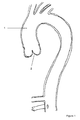
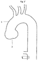
- the aorta includes an ascending aorta 1 which receives blood from the heart through an aortic valve 2.
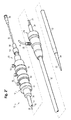
- an implant deployment assembly 10 includes an external manipulation section 12, a proximal attachment region 14 and a distal attachment region 16.
- the proximal attachment region 14 and the distal attachment region 16 secure the two ends of an implant 18.
- the proximal and distal attachment regions 14 and 16 will travel through the patient's vasculature, in this example, to a desired deployment site.
- the external manipulation section 12 at the proximal end of the implant deployment assembly 10, which is operated by a surgeon to manipulate the introducer, remains outside of the patient throughout the procedure.
- the distal attachment region 16 of the implant deployment assembly 10 includes a dilator tip 20, which is typically provided with a bore 22 therein for receiving a guide wire (not shown) of conventional type.
- the longitudinal bore 22 also provides a channel for the introduction of medical reagents. For example, it may be desirable to supply a contrast agent to allow angiography to be performed during placement and deployment phases of the medical procedure.
- the guide wire carrier 24 is flexible so that the implant deployment assembly 10 can be advanced along a relatively tortuous vessel, such as a femoral artery, and so that the distal end of the implant deployment assembly 10 can be longitudinally and rotationally manipulated.
- the guide wire carrier 24 carries a stent 18 or other device to be implanted in the patient.
- the guide wire carrier 24 extends through the implant deployment assembly 10 to the manipulation section 12, terminating at a connection device 26, in conventional manner.
- connection device 26 is designed to accept a syringe to facilitate the introduction of reagents into the guide wire carrier 24 and for this purpose is typically provided with a threaded luer lock connection.
- a pusher sheath or rod 30 (hereinafter referred to as a pusher member), typically made from a plastics material, is mounted coaxial with and radially outside of the guide wire carrier 24.
- the pusher member 30 is "thick walled", that is the thickness of its wall is preferably several times greater than that of the guide wire carrier 24.
- the pusher member 30 and the guide wire carrier 24 are the same component, possibly having different outer diameters at the location at which the stent 18 is to be carried.
- a retractable sheath 32 extends coaxially over and radially outside of the pusher member 30.
- the pusher member 30 and the sheath 32 extend distally to the manipulation region 12.
- the implant 18 is retained in a compressed condition by the sheath 32.
- the sheath 32 extends proximally to a sheath manipulator and haemostatic sealing unit 34 of the external manipulation section 12.
- the haemostatic sealing unit 34 includes a haemostatic seal (not shown) and a side tube 36 held to the unit 34 by a conventional luer lock 38.
- the sheath manipulator and haemostatic sealing unit 34 also includes a clamping collar (not shown) that clamps the sheath 32 to the haemostatic seal and a silicone seal ring (not shown) that forms a haemostatic seal around the pusher member 30.
- the side tube 36 facilitates the introduction of medical fluids between the pusher member 30 and the sheath 32. Saline solution is typically used.
- the sheath 32 is advanced over the proximal end of the dilator tip 20 of the distal attachment region 16 while the implant 18 is held in a compressed state by an external force.
- a suitable distal attachment (retention) section (not visible in this view) is coupled to the pusher member 30 and retains a distal end 40 of the prosthesis 18 during the procedure.
- the distal end of the prosthesis 18 may be provided with a loop of material (not shown) through which release wires 42 extend.
- the release wires also extend through an aperture (not shown in Figures 2 and 3 ) in the proximal attachment section 14 into an annular region 44 between the guide wire carrier 24 and the pusher member 30.
- the release wires 42 extend through the annular space 44 to the manipulation region 12 and exit the annular space 44 at one or more release wire mechanisms or actuation sections 50.
- the external manipulation section 12 includes at least one release wire actuation section 50 mounted on a body 48, in turn mounted onto the pusher member 30.
- the guide wire carrier 24 passes through the body 48.
- the release wire mechanisms 50 are mounted for slidable movement on the body 48.
- Clamping screws 52 prevent inadvertent early release of the prosthesis 18.
- a haemostatic seal (not shown) is included so that the release wires can extend out through the body 48 without unnecessary blood loss during the medical procedure.
- a proximal portion of the external manipulation section 12 includes a pin vice 54 mounted onto the proximal end of the body 48.
- the pin vice 54 has a screw cap 56.
- vice jaws (not shown) of the pin vice 54 clamp against or engage the guide wire carrier 24.
- the guide wire carrier 24 can only move with the body 48 and hence it can only move with the pusher member 30.
- the screw cap 56 tightened, the entire assembly can be moved together as one piece.
- the sheath 32 is withdrawn and the release wire mechanisms 50 are released to allow the prosthesis 18 to expand.
- the sheath 32 may be left in place after expansion of the implant 18.
- the pusher member 30 and guide wire carrier 24 may be withdrawn and replaced by a further component, using the sheath 32 as a guide.
- the guide wire carrier 24 can sometimes be described, both above and in the description which follows, as a centre guide wire carrier, as a cannula or as a sheath and in all of the embodiments described herein it could take any of these forms. It is also to be understood that although some embodiments described below make use of a guide wire carrier as well as an introducer carrier, this is not an essential combination as it is envisaged that in some embodiments a guide wire may be carried within the introducer carrier, that is without any separate guide wire carrier or cannula.
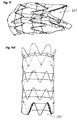
- Figure 4 shows an implant or medical device 18 in the form of a stent graft for being deployed with an introducer assembly 10' which may be of the type illustrated in Figures 2 and 3 .
- Figure 4 shows the stent graft 18 in an expanded state as it would be after being fully deployed.
- the stent graft 18 is intended for being deployed in the ascending aorta, in close proximity to the aortic valve.
- medical devices according to other embodiments of the invention could be used for deployment in other parts of the human or animal vasculature.
- the stent graft 18 of the embodiment of Figure 4 includes a tubular graft 112 of biocompatible material with a lumen therethrough and having a longitudinal axis.
- the stent graft 18 has a proximal end 114 and a distal end 116.
- the stent graft may include a scallop 127 at the distal end of the stent graft arranged to be located on the outside of the curve of the aortic arch on implantation.
- the scallop 127 is shown in Figures 6 , 6A and 41 and particularly in Figure 9A' .
- the scallop may be of the configurations shown in the figures and described in the accompanying text of U.S. Patent No. 7,413,573 to Hartley et al. , incorporated by reference herein.
- the scallop may be disposed between an adjacent pair of struts of the distal end stent 120 with no struts crossing the scallop or it may be disposed between a pair of struts with one or more struts between the pair of struts crossing the scallop.
- the periphery of the scallop may be partially stitched to one or more struts disposed along the periphery of the scallop.
- the scallop is designed and configured to align with one of the arteries of the arch (as shown in Figure 1 ), such as the innominate artery, so as to not block that artery.
- the stent graft 18 includes a proximal end stent 118 and a distal end stent 120.
- the proximal end stent 118 is a bare stent located at and extending beyond the proximal end 114 of the stent graft 18.
- the longitudinal length of the bare stent from proximal to distal apices is about 15mm.
- the diameter of the bare stent tapers from a first diameter at its proximal end to a second smaller diameter at its distal end thereby forming a frusto-conical shape.
- the proximal end stent has proximal apices and distal apices.
- the proximal apices may have a larger radius of curvature than the distal apices so as to present an atraumatic end of the stent graft.
- the distal end stent 120 is located at the distal end 116 of the stent graft 18 but does not extend distally of the graft material. In other words, the distal end stent is also the last covered stent.
- the distal end stent can be a bare stent extending beyond the distal end of the graft material of the same or similar construction as the proximal bare stent, and/or the proximal end stent can be a non-bare stent and can be the first covered stent.
- the stent graft 18 includes a first covered stent 122' which is a different stent from the proximal end stent, but which is adjacent to the proximal end stent.
- the stent graft 18 also includes a plurality of intermediate stents 122 which are provided on the graft 112 between the first and last covered stents 122', 120.
- the first and last covered stents and all the intermediate stents are covered, that is covered over their full longitudinal extent on at least one surface, with graft material.
- the stents may have a zig zag shape and are what is commonly known as Gianturco type stents or z-stents.
- the stents can be spaced on the graft 112 substantially equidistantly or with different distances between different sets of adjacent stents. In some embodiments, the stents can be provided in close proximity with minimal distances between adjacent stents. As shown, the stents are discrete, meaning separate, and not connected to each other except indirectly by way of the graft material.
- the distal end stent 120 and the first covered stent 122' are internal stents whereas the intermediate stents 122 are external stents.
- each stent can be either internal or external.
- internal stent what is meant is that the stent is located on the internal surface of the graft and therefore has graft material on its outer side, whereas an “external stent” is located on the external surface of the graft and therefore has graft material on its inner side.
- proximal end stent 122' and the distal end stent 120 are internal so as to present a smooth landing surface of the stent graft for graft to vessel apposition to ensure a tight interface.
- Each of the stents is attached to the graft 112, for example by sutures in a conventional manner.
- Figure 4 shows two intermediate stents 122. However, in other embodiments there can be other numbers of intermediate stents.
- Each of the stents of the stent graft is provided with a constraining mechanism for constraining the respective stent.
- the constraining mechanisms for the proximal and distal end stents are not visible in the expanded state of Figure 4 .
- the constraining mechanism 124 for each of the intermediate stents 122 is for constricting the respective stent.
- the constraining mechanism 124 for each of the intermediate stents is configured in a constricting configuration to constrict substantially the entire length and circumference of the respective stent, the length being in a longitudinal direction.
- the constraining mechanism 124 for each of the intermediate stents 122 includes first and second constriction elements.
- the first constriction element includes a first thread 126 and the second constriction element includes a second thread 128. Both the first and second threads can be made of suture material.
- the first thread 126 is attached to and extends around substantially the entire circumference of a proximal section of the respective intermediate stent 122 whereby to constrict the proximal section of the respective intermediate stent when in a constricting configuration.
- the second thread is attached to and extends around substantially the entire circumference of a distal section of the respective intermediate stent 122 whereby to constrict the distal section of the respective intermediate stent when in a constricting configuration.
- the threads can pass radially internally of the struts of the stent, radially externally of the struts of the stent, or a mixture of radially internally and radially externally.
- each thread may alternate around the circumference of the stent between passing radially internally and radially externally of the struts.
- the first and second threads may pass around the inside of odd-numbered struts and the outside of even-numbered struts and thereby be threaded inside and outside the struts in an alternating manner around the circumference of the respective stent.
- the first thread 126 extends about the circumference of the exterior of the graft at or near the proximal apices and the second thread 128 extends about the circumference of the exterior of the graft at or near the distal apices of intermediate stent 122.
- the first and second threads 126, 128 may extend through the graft material to the interior of the graft for a short distance.
- the first and second threads 126, 128 may extend around the circumference of the respective stent and be tied to each strut, or at least tied to a plurality of struts such as every second strut at or near the apices.
- Each of the first and second threads 126, 128 forms a loop with a length which is substantially equal to an uncompressed circumference of the respective stent section, or at least which is not less than an uncompressed circumference of the respective stent section.
- each of the threads is restrained at a plurality of locations around its loop as described below in order to provide a constricting function and thereby to prevent the respective stent section from expanding to its full deployment diameter.
- the first and second constriction elements in this case the first and second threads 126, 128, are in a fully constricted configuration configured to constrain the respective stent section to a diameter of no more than half or more preferably no more than a third of its fully deployed diameter.
- the constraining mechanism for the first covered stent 122' includes a single constriction element 130.
- the constriction element 130 corresponds to the first constriction element 126 of the intermediate stents 122.
- the constriction element for the first covered stent 122' is positioned about the circumference of the stent and graft and weave in and out of the graft material at one or more apices, and in particular as shown in Figures 4 and 5 at one or more proximal apices of the first covered stent 122'.
- Figures 5 to 11 show how the constraining mechanisms of the first covered stent and the intermediate stents are held in a constricting configuration by the release wires until withdrawal of the release wires.
- Figures 5 to 11 also show the constraining mechanisms for the proximal and distal end stents.
- release wires 42 which pass longitudinally through the lumen of the stent graft 18.
- the number of release wires is not important.
- the deployment assembly 10' has, in this embodiment, a guide wire carrier 24 and a release wire carrier 8 (typically the carrier of the introducer for carrying the medical device) located coaxially around the guide wire carrier 24, such that the guide wire carrier resides in a lumen of the release wire carrier 8.
- the guide wire may be located directly in the release wire carrier 8 thus avoiding the need for a separate guide wire carrier 24.
- the release wires 42 pass along the annular space between the guide wire carrier 24 and the release wire carrier 8.
- Figure 5 is a perspective view from the proximal end of the medical device when mounted on an introducer device and with all of the constraining mechanisms in a constraining configuration.
- Figure 5A is a side view thereof.
- the proximal end stent 118 includes a constraining mechanism 132 at a proximal retaining or attachment region 14.
- each release wire has associated first and second apertures 107 in the release wire carrier 8. The release wire extends out of the release wire carrier 8 through its first associated aperture 107, passes over one or more proximal apices of the proximal end stent 118, and passes back into the release wire carrier 8 through its second associated aperture 107.
- each release wire at the proximal retaining section passes over and thereby constrains approximately one third of the proximal apices of the proximal end stent 118.
- the number of release wires is not important and a different number of release wires could be used, with each wire being attached to a different fraction of the proximal apices of the proximal end stent.
- other means of attaching release wires to the proximal end stent as known in the art can be used.
- one or more release wires play no role in the constraining mechanism 132.
- the assembly 10' includes a pusher sheath or rod 30.
- the release wire carrier 8 and the pusher sheath 30 have sets of aligned apertures 117.
- Each set of apertures 117 includes a first aperture in the release wire carrier 8 aligned with a first aperture in the pusher sheath and a second aperture in the release wire carrier aligned with a second aperture in the pusher sheath.
- Each release wire 42 extends from the release wire carrier out of its respective first apertures to the outside of the pusher sheath 30.
- the release wire passes over one or more distal apices of the distal end stent 120 on the outside of the pusher sheath 30 and then extends back into the release wire carrier through the respective second apertures.
- the release wires 42 for the distal end stent 120 may be the same as or different release wires from the release wires 42 for the proximal end stent 118.
- the constraining mechanism 134 constrains the distal end stent on the pusher sheath. This is advantageous as it can assist the pusher sheath with advancing the stent graft.
- the sets of apertures 117 can be provided just in the release wire carrier and not in the pusher sheath so that the pusher sheath is not directly attached to the distal end stent.
- One or more or all release wires can each hold a plurality of distal apices. In some embodiments, one or more release wires play no role in the constraining mechanism 134. In embodiments, all distal apices of the distal end stent are restrained by a release wire. In other embodiments, other means of constraining the distal apices of the distal end stent can be used.
- proximal apices of the proximal end stent and the distal apices of the distal end stent can be coupled to the release wires such that the release wires can be withdrawn so as to release the apices.
- Other possible techniques for providing constraining mechanisms for the proximal and distal end stents are disclosed in WO2006/037086 , which is incorporated herein by reference in its entirety.
- Figures 7 to 11 show more clearly how the constriction elements of the constraining mechanisms of the first covered stent and the intermediate stents are coupled to the release wires.
- Figure 7 is a view of the assembly of Figure 5 but showing more clearly the constriction element 130 of the first covered stent 122'.
- the thread of the constriction element 130 passes around an outer surface of the graft 112 where it is attached to the first covered stent.
- the thread 130 is continuous around the full circumference of a proximal section of the first covered stent, adjacent to the proximal end of the graft.
- the thread 130 is tied to the first covered stent.
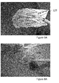
- Figures 8 and 8A shows the assembly of Figures 5 to 7 but in which the proximal end stent has been released from the constraining mechanism 132.
- the thread 130 passes through the graft to the interior of the graft, is passed around one or more of the release wires 42, and passes back out of the graft to the exterior of the graft.
- a bight of the thread is restrained by one or more release wires.
- the release wire can extend out of and back into its respective aperture to form an arc or loop.
- the aperture can be in the form of first and second apertures allowing the respective release wire to extend out through a first aperture and back in through a second aperture in a similar manner to the apertures 107 described above.
- the release wires do not extend through the apertures but are simply exposed within the release wire carrier 8 by the apertures 7.
- a bight 131 of the thread 130 passes around one or more release wires.
- the thread is thereby restrained by the release wires at the restraining locations, constricting the diameter of the proximal section of the first covered stent.
- the thread 130 passes through the graft at points either side of a strut of the first covered stent in the vicinity of a proximal apex thereof.
- the bight 131 of thread at each restraining location can be considered to include a first length on one side of its coupling to the release wires and a second length on the other side of its coupling to the release wires, the first length passes through a proximal apex of the first covered stent and the second length passes through the graft adjacent to that proximal apex.
- the thread 130 may be attached directly to the first covered stent at or adjacent to the points at which it passes through the graft.
- the thread does not need to pass through the graft in the vicinity of apices in all embodiments but can pass through the graft at any points.
- the thread is attached to a first point of a first strut where it passes through the graft into the interior of the graft and is attached to a second point of a second strut where it passes through the graft out of the interior of the graft.
- the first and second points are points on adjacent struts either side of and close to an apex. In this way, the struts can act to hide or shield the thread from any other medical device or components inside the graft.
- the thread 130 is held in a constricting configuration, thereby constricting the proximal end of the first (proximal) covered stent 122'.
- the thread 130 is released from the constricting configuration condition and allows the proximal section of the first covered stent to expand beyond its constricted diameter.
- Two of the release wires constrain one bight 131 of the thread 130 each.
- One of the release wires constrains two bights 131 of the thread 130.
- the number of release wires is not important.
- the number of bights of threads and restraining locations is also not important. It is possible to have any number of release wires and any number of bights of thread. In one embodiment, there are 6 bights 131 of the thread.
- each release wire can restrain one bight of the thread, although it is not always necessary for every release wire to restrain a bight 131 of the thread. In some embodiments, especially if there are more bights of the thread than release wires, one or more release wires may restrain more than one bight of the thread.
- the release wires When the release wires are pulled, because their ends during withdrawal terminate at different longitudinal positions, the bights will be released separately and hence sequentially to sequentially circumferentially expand the restrained stent. In other words, one portion of the stent will expand first and then the remaining portions of the stent will expand, one after the other in a sequential fashion.
- the number of bights of the thread and the number of release wires is dependent on the size of the stent graft and the number of apices on a stent. For example, for a 42mm stent graft, there may be 8 bights of the thread. However, in many situations, it has been found that 4 bights of the thread works well.
- each release wire can have a dedicated aperture associated with the thread 130, or a single aperture may expose more than one release wire for coupling to the thread.
- the release wires are the same length and independently operable, that is, they can be withdrawn in a staggered fashion so as to release different parts of the constraining mechanism at different times. This can be achieved by coupling them to their own dedicated actuation sections 50 as shown in Figures 2 and 3 and withdrawing them so that distal ends of the release wires terminate at different longitudinal positions during withdrawal so as to be withdrawn from and release different couplings of the constraining mechanism at different times.
- the release wires are different lengths and designed to be withdrawn together so as to release different parts of the constraining mechanism and hence different sides of the graft at different times, thereby effecting a similar staggered withdrawal.
- distal ends of the release wires can be held at the distal end of the assembly, for example in the nose cone dilator, at different longitudinal distances from the stent graft, whereby the stent graft is positioned between the distal ends of the release wires and the actuation sections 50.
- Releasing different parts of the constraining mechanism at different times can allow the proximal section of the first covered stent to expand beyond its constricted diameter to its uncompressed or fully deployed diameter in stages. This can provide for expanding the graft constrained by the constraining method sequentially around its circumference. This permits the proximal end of the stent to conform to the curved vessel with no gaps between the vessel wall and the graft end.
- the release wires are typically designed to be withdrawn so that there is only a very short interval between the release of different parts of each constrained stent section, and there is only a short interval between the release of adjacent stent sections.
- the release wires are preferably configured to be withdrawn so that each constrained stent is completely released from the release wires before any part of the next constrained stent in the direction of withdrawal is released from the release wires.
- a longitudinal distance between a distal end of the release wire that extends furthest into the nose cone dilator, and a distal end of the release wire that extends least far into the nose cone dilator may be less than a minimum longitudinal distance between couplings of adjacent constraining mechanisms.
- the first stent is released in stages around its circumference first, then the next stent is released around its circumference and so on.
- the proximal end of the first intermediate stent can be released circumferentially in stages, followed by the distal end being released circumferentially in stages, followed by release of the proximal end of the next immediate stent in circumferential stages, followed by release of the distal end of the next immediate stent is circumferential stages, and so on depending on the number of intermediate stents.
- the thread 130 can form a loop substantially corresponding to the expanded circumference of the stent section.
- the restraining locations and therefore the bights of thread are at regular angular intervals around the proximal section of the first covered stent in order to provide an even constricting effect.
- the restraining locations and bights of thread do not need to be at regular angular intervals.
- the thread 130 does not in all embodiments need to be generally external to the graft provided that it is disposed with respect to the first covered stent so as to be able to constrict the proximal section of the first covered stent when restrained at the restraining locations. Therefore, the bights are not in all embodiments associated with points at which the thread passes through the graft; the thread may in some embodiments already be internal to the graft, especially if the stent is an internal stent.
- Each bight can be a length of the thread, from a first point of attachment of the thread to the graft and/or stent, to a second point of attachment to the graft and/or stent, wherein the bight passes around one or more of the release wires between the first and second points of attachment.
- Each of the threads of the constraining mechanisms of the intermediate stents can be attached to the release wires in a corresponding manner.
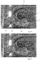
- Figures 9 and 9A show the assembly of Figure 5 but in which the constraining mechanism 130 of the first covered stent has been released.
- Figure 9 shows more clearly the constraining mechanism of the intermediate stent 122 adjacent to and distal of the first covered stent 122'.
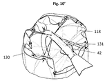
- Figures 10 and 10A show the assembly of Figure 5 but in which the constraining mechanisms 130, 124 of the first covered stent and the intermediate stent adjacent to and distal of first covered stent have been released.
- Figure 10 shows more clearly the constraining mechanism of the intermediate stent 122 which is distal of the first covered stent 122' and separated therefrom by one stent.
- the constraining mechanisms of the stents of the stent graft are coupled or include couplings to the release wires in the same order along the release wires from the proximal end to the distal end of the stent graft as the order from the proximal end to the distal end of the stent graft of the stent sections that they constrain. This means that withdrawal of the release wires in a direction away from the heart releases those stent sections in order from the proximal to the distal end of the stent graft.
- Figure 11 shows a longitudinal cross-section through a part of the assembly 10' in the region of an intermediate stent 122.
- Figure 11 does not show the stent 122 itself as only the internal surface of the graft 112 is visible in Figure 11 whereas the stent 122 is an external stent.
- the bights of the threads 126, 128 can only be seen for the sections that are internal to the graft 112.
- the deployment assembly 10' has, in this embodiment, a guide wire carrier 24 and a release wire carrier 8 (typically the carrier of the introducer for carrying the medical device) located coaxially around the guide wire carrier 24, such that the guide wire carrier resides in a lumen of the carrier 8.
- the guide wire may be located directly in the release wire carrier 8 thus avoiding the need for a separate guide wire carrier 24.
- the release wires 42 pass along the annular space between the guide wire carrier 24 and the release wire carrier 8. For each thread 126, 128, each release wire is exposed by an aperture 7 in the release wire carrier 8. At each of the apertures 7, one of the release wires exits through the aperture 7, where at least one bight passes around it. The release wire then re-enters the annular space between the guide wire carrier and the release wire carrier.
- the apertures 7, release wires and bights can be configured in other fashions such as discussed above for the first covered stent.
- the release wires eventually pass into the nose cone dilator 20 at the distal end of the assembly to be secured thereby.
- a guide wire passes through the lumen of the guide wire carrier, catheter or cannula 24 in conventional manner.
- the apertures 7 and/or the restraining locations associated with each thread 126, 128 may be equally spaced around the release wire carrier. In this embodiment, the apertures are spaced at approximately 120° to each other and the restraining locations are spaced at approximately 90° to each other. However, as discussed above, the number of restraining locations and release wires is not important.
- the assembly is operated as described below, with reference to Figures 5 to 10 and 12 to 21 .
- the device 18 is compressed in the sheath 32 with all of the constraining mechanisms in a constraining configuration.
- the stent graft 18 is advanced in a known manner to a deployment site, in this example being the ascending aorta 1 of a patient.
- Figures 12-21 show an experimental mock up with a tube designed to imitate the aorta of a patient.
- the region designed to imitate the ascending aorta of a patient is labelled 1'.
- the sheath is withdrawn in a known manner leaving the situation shown in Figure 12 . This corresponds to the stent graft being in the configuration shown in Figures 5 and 5A .
- the stent graft Owing to the constriction elements constricting the intermediate stents 122, the constriction element 130 constricting the first covered stent 122', and the constraining mechanisms at the proximal and distal retaining sections, the stent graft has not fully deployed in Figure 12 despite the withdrawal of the sheath.
- the constraining mechanisms constrain the stents to no more than half or no more than a third of their unconstrained and fully deployed diameter. This enables the stent graft to be imaged and easily repositioned if it is in the incorrect location.
- a line 138 is shown which marks a substantially perpendicular direction with respect to the ascending aorta and identifies a position which should be taken by the first covered stent when deployed.
- the release wires 42 are the same length and withdrawn in a staggered fashion.
- the release wires can be withdrawn concurrently but staggered so that during withdrawal each release wire is at a different stage in its withdrawal process, that is to say the distal end of each release wire terminates at a different longitudinal position during withdrawal.
- the release wires may in other embodiments be different lengths and withdrawn together, thereby also effecting a staggered withdrawal so that during withdrawal the distal end of each release wire terminates at a different longitudinal position.
- the release wires can be the same length and withdrawn together.
- the release wires are preferably withdrawn so as to completely release each constrained stent from the release wires in a circumferentially staged manner before any part of the next constrained stent in the direction of withdrawal is released from the release wires. This is to ensure that the constrained stents are released in sequence from the proximal end to the distal end of the stent graft.
- the proximal apices of the proximal end stent are no longer constrained and can spring open.
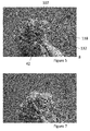
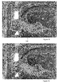
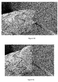
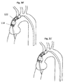
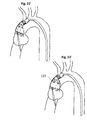
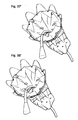
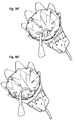
- the apices of the proximal end stent 118 are released and spring open in stages, as the release wires release different sets of apices at different times. This is shown in Figures 22 to 25 , and allows a gradual expansion process.
- the release wires are withdrawn proximally of (in other words closer to the operator than) the bights 131 of the thread of the constriction element 130 of the first covered stent, the bights 131 of the constriction element 130 are released and the constriction element 130 of the first covered stent no longer provides a constricting function and the first covered stent can spring open.
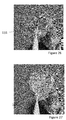
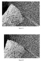
- the bights 131 of the thread of the constriction element 130 of the first covered stent are released in stages, as the release wires release the bights from different restraining locations at different times. This is shown in Figures 26 to 29 , and allows a gradual expansion process for the proximal section of the first covered stent 122'.
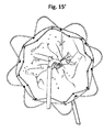
- Figures 9 and 15 show the position after the constriction element of the first covered stent has been released. As can be seen in Figure 15 , the first covered stent has begun to expand towards its fully deployed diameter. However, because of the constriction elements constricting the intermediate stents, the proximal end stent 118 is unable to completely fully deploy.
- the constriction elements of the first intermediate stent are released and therefore provide no more constricting function, and the first intermediate stent can expand towards its full deployed diameter.
- each release wire is withdrawn in sequence from the bights by which it is coupled to the constraining mechanism.
- the bights of this constraining mechanism can be considered to be arranged in sets, with each release wire being coupled to a set of bights of the constraining mechanism.
- a set of bights for a particular release wire includes any bights of the thread 126 of the first constriction element to which it is coupled as well as any bights of the thread 128 of the second constriction element to which it is coupled.
- Each set of bights is released from its respective release wire in turn so that all bights of a given set are released before any bights from the next set to be released.
- the constraining mechanism 124 as a whole is gradually released, allowing the first intermediate stent to expand.
- the first constriction element 126 can be entirely released before any bights of the second constriction element 128.
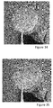
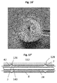
- Figure 31 shows one circumferential section released as a release wire is pulled.
- Figure 32 shows the next circumferential section released.
- Figure 34 shows the next circumferential section released, and
- Figure 35 shows the last circumferential section released such that the first covered stent is completely released.
- Figures 10 and 17 show the positon after the release wires 42 have been withdrawn proximally of (in other words closer to the operator than) the bights of the constriction elements of the first intermediate stent 122.
- the constriction elements of the first intermediate stent at this stage provide no more constricting function, and the first intermediate stent can expand towards its full deployed diameter.
- the distal apices of the distal end stent are no longer constrained and can spring open.
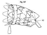
- the apices of the distal end stent are released and spring open in stages, as the release wires release different sets of apices at different times. This is shown in Figures 40 to 43 , and allows a gradual expansion process.
- the scallop 127 is located in the vicinity of the first set of apices of the distal apices of the distal end stent to spring open, but this is not necessary in all embodiments.
- the ordered release of the stents from their constraining mechanisms in this manner enables the expansion of each stent both to be guided by, and to assist, the expansion of the adjacent proximal stent, thereby enabling the stent graft to expand in a smooth and reliable manner into its desired position within the vessel.
- embodiments of the invention enable careful repositioning after retraction of the sheath but before full deployment and a smooth and accurate deployment of the stent graft.
- This is particularly advantageous in the ascending aorta where it is difficult to manipulate a deployment device owing to the significant curvature of the aortic arch, and where also it is important to ensure an accurate and reliable placement.
- constriction elements in this embodiment still allow the stents to expand in a substantially symmetrical fashion. This has been found to cause a gradual transition from a constricted configuration to a released configuration, with a gradual increase in diameter.
- the release of all the constraining mechanisms is preferably performed as a quick procedure to minimise the risk of the blood flow dislodging the device as it is being deployed.
- release wires are withdrawn in a staggered fashion so each constraining mechanism is released in stages, it is possible for the release wires to be withdrawn together to cause all couplings of the stent graft to the release wires that are at substantially the same longitudinal positions to be released substantially together.
- each of the release wires operates all of the constraining mechanisms, in some embodiments there are different release wires for different constraining mechanisms.
- each release wire may operate one or more constraining mechanisms, possibly in combination with one or more further release wires.
- One embodiment includes a set of release wires for operating the proximal-most and distal-most constraining mechanisms, and a separate set of release wires for operating the other constraining mechanisms.
- the proximal-most and distal-most constraining mechanisms may be released, in the manner described above, but after the other constraining mechanisms.
- the proximal and distal end stents may each be retained by a retention mechanism and released in a different procedure from the constraining mechanisms which constrain the stents between them.
- the proximal and distal end stents may be deployed after the constraining mechanisms which constrain the stents between them have been released.
- the retention mechanisms may be similar to the constraining mechanisms for the proximal and distal end stents described above and may include features of the constraining mechanisms discussed above.
- a retention mechanism actuation mechanism which may be separate from but similar to, the actuation mechanism discussed above, may be provided including a plurality of retention mechanism release wires or rods, and each of the retention mechanisms may include a plurality of couplings to the retention mechanism release wires or rods, the retention mechanism release wires or rods being operable to be withdrawn from the couplings to release the retention mechanisms.
- the retention mechanism release wires or rods may have ends which during withdrawal terminate at different longitudinal positions whereby to release different couplings of each of the retention mechanisms at different times whereby to release each of the retention mechanisms in stages.
- the distal end stent is the last stent to be deployed.
- each of the threads of the constriction elements is described as being a single thread that extends around substantially the entire circumference of the respective stent section, it is possible for one or more or all of these threads to be replaced by a plurality of threads each extending around a part of the circumference of the respective section of the respective stent and each being attached to a release wire 42 at a restraining location.
- Figure 39 shows a constriction element 330 for the first covered stent 318.
- the constriction element 330 four lengths of suture thread 128' each attached to a plurality of stent apices.
- Each suture thread 128' is located generally on the outside of the graft material 112 apart from a length or bight which feeds to the inside of the graft material 112, although as described above it is not necessary for the threads to be outside the graft material in every embodiment.
- This length or bight can be fed through one of the openings 7 in the release wire carrier 8 and restrained by a release wire therein.
- the other constriction elements for the stent graft may be correspondingly arranged.
- the threads do not always have to be attached to the apices of the stent, but can for example be attached to struts between the apices. However, the number of lengths of thread and the number of apices or struts to which each length of thread is attached can be varied.
- constriction element it is not necessary in all embodiments for every constriction element to be directly attached to the stent that it is designed to constrict.
- one or more or all constriction elements can be configured to constrict the graft material, for example by attachment thereto, in proximity to the respective stent and thereby constrict the respective stent by virtue of the attachment of the stent to the graft material.
- one or more or all of the threads of the constriction elements can be replaced by a plurality of non-circumferential threads, each of the non-circumferential threads being at a restraining location and being tied to the respective release wire and attached to the graft and/or stent, thereby tying the medical device to the release wires at the restraining locations.
- the constricting function is provided by the medical device being pulled radially inwards at the restraining locations and without a circumferential constriction element thread assisting in the constriction.
- a single thread extending around substantially the entire circumference is advantageous as it is believed to efficiently constrict the entire circumference of the stent graft.
- first and second constriction elements for all intermediate stents
- these stents, or at least some of these stents are provided with a single constriction element which is preferably, but not necessarily, located at a longitudinally substantially central region of the respective stent. Nevertheless, these constriction elements are preferably configured to constrict substantially the full longitudinal extent of their respective stents.
- the constraining mechanism for the first covered stent 122' can be provided with first and second constriction elements as per the intermediate stents, or the constriction element of the first covered stent 122' can be located to constrict a distal section of the first covered stent in a manner corresponding to the second constriction element of the intermediate stents.
- one or more constriction elements corresponding to the constriction elements of the intermediate stents can be provided for the distal end stent 120 in addition to or instead of the constraining element for the distal end stent described above.
- the proximal end stent is a bare stent
- the bare stent it is possible for the bare stent to be omitted, meaning that the first covered stent is also the proximal end stent.
- the first covered stent can be constrained by a tri-fold constraining mechanism such as disclosed in US 2010/0114291 , which is incorporated herein by reference in its entirety. This can be in addition to or instead of a constriction element such as described above.
- the first covered stent includes a constriction element at the distal section of the stent corresponding to the second constriction element 128 of the intermediate stents as described above as this has been found to provide a particularly reliable positioning for the proximal end stent, enabling the proximal end stent to expand against the walls of a vessel in which it is deployed so that the struts of the stent are substantially parallel to the vessel wall.
- US 2010/0114291 discloses a tri-fold constraining mechanism primarily for the proximal stent, such a constraining mechanism can be used for the distal end stent of embodiments of the present invention instead of or in addition to the constraining mechanism described above.
- the stent graft can be provided with a mechanism for controlling the curvature of the stent graft such as disclosed in WO 2009/126227 , which is incorporated herein by reference in its entirety.
- the proximal end of the graft can be provided in a sinusoidal or otherwise scalloped shape such as is disclosed in WO 2010/129685 , which is incorporated herein by reference. This can assist in packing efficiency. It can also minimise loose material between the stent struts at the proximal end of the graft if the first covered stent is not quite at its full deployment diameter. This is often the case as it is generally preferred for a stent graft to be slightly oversized for the vessel so that it imparts a radially outward force on the vessel wall.
- a scalloped edge at the proximal end of the graft for example to provide for receiving a side branch prosthesis for example from the innominate artery.
- thread as used herein is intended to include any filamentary material which can perform the stated function and could, for example, be of conventional suture material, a multi-filamentary structure formed of yarns for example and of a natural or synthetic material such as cotton, other biocompatible material or a polymer material such as polyester, or a mono-filamentary structure of a natural material, other biocompatible material, a metal such as gold or an alloy such as Nitinol.
- the stent graft can include a prosthetic valve, for example a prosthetic heart valve can be positioned at a proximal end of the stent graft.
Landscapes
- Health & Medical Sciences (AREA)
- Engineering & Computer Science (AREA)
- Biomedical Technology (AREA)
- Cardiology (AREA)
- Oral & Maxillofacial Surgery (AREA)
- Transplantation (AREA)
- Heart & Thoracic Surgery (AREA)
- Vascular Medicine (AREA)
- Life Sciences & Earth Sciences (AREA)
- Animal Behavior & Ethology (AREA)
- General Health & Medical Sciences (AREA)
- Public Health (AREA)
- Veterinary Medicine (AREA)
- Gastroenterology & Hepatology (AREA)
- Pulmonology (AREA)
- Prostheses (AREA)
- Media Introduction/Drainage Providing Device (AREA)
Abstract
Description
- The present invention relates to assemblies including implantable medical devices, for example stent grafts, in embodiments including a constriction mechanism.
- Stent grafts are often positioned in the descending aorta, for example for treating aneurysms. However, sometimes it is necessary to implant a stent graft in the ascending aorta, that is in close proximity to the aortic valve.
- Positioning a stent graft in the ascending aorta can be difficult because the deployment device generally extends up the descending aorta, around the aortic arch, and into the ascending aorta. However, the passing of the deployment device over the aortic arch can cause a significant amount of the control that the operator has over the deployment device to be lost owing to the significant curvature of the aortic arch. Furthermore, owing to the location of the ascending aorta being in close proximity to the aortic valve, it is important when positioning stent grafts in the ascending aorta that they are placed accurately.
- The present invention seeks to provide an improved implantable medical device assembly and method for deployment thereof.
- According to an aspect of the invention there is provided an assembly for deploying a stent graft, including:
- a stent graft having a first end, a second end, a tubular structure, and a length, and including a first end stent at the first end of the stent graft, a second end stent at the second end of the stent graft, and at least one stent between the first end stent and the second end stent;
- a plurality of constraining mechanisms arranged along the length of the stent graft, each of the constraining mechanisms being releasable; and
- an actuation mechanism including a plurality of release wires or rods;
- wherein each of the constraining mechanisms includes a plurality of couplings to the release wires or rods, the release wires or rods being operable to be withdrawn from the couplings to release the constraining mechanisms; wherein the release wires or rods have ends which during withdrawal terminate at different longitudinal positions whereby to release different couplings of each of the constraining mechanisms at different times whereby to release each of the constraining mechanisms in stages.
- In embodiments, the release wires or rods are configured for a staggered withdrawal, which can provide for a gradual transition for each of the constraining mechanisms from a constricted configuration to a released configuration, with a gradual increase in diameter while allowing the stents to expand in a substantially symmetrical fashion.
- In embodiments, the couplings of each of the constraining mechanisms to the release wires or rods are angularly or circumferentially spaced with respect to the stent graft.
- In embodiments, the actuation mechanism is operable to release the constraining mechanisms which constrain the stents between the first and second end stents in order from the first end to the second end of the stent graft.
- The term longitudinal can mean with respect to a longitudinal axis of the stent graft.
- According to an aspect of the invention, there is provided an assembly for deploying a stent graft, including:
- a stent graft having a first end, a second end, a tubular structure, and a length, and including a first end stent at the first end of the stent graft, a second end stent at the second end of the stent graft, and at least one stent between the first end stent and the second end stent;
- a plurality of constraining mechanisms arranged along the length of the stent graft and configured to constrain all of the stents of the stent graft, each of the constraining mechanisms being releasable; and
- an actuation mechanism operable to release the constraining mechanisms in order from the first end to the second end of the stent graft.
- The inventors have discovered that by providing a stent graft in which all of the stents can be released sequentially in order from the first to the second end and in a circumferentially staggered fashion, the stent graft can be deployed in a very smooth manner, in many cases avoiding significant jolts or jumps which might cause the stent graft to move out of position. This is particularly advantageous in the ascending aorta where accuracy of position is important owing to the closeness of the aortic valve.
- In addition, where all the stents are constrained, a deployment sheath can be completely removed from the medical device without portions of the medical device springing open too far. This can mean that the stent graft can easily be repositioned after withdrawal of the sheath, to ensure that it is in the correct position before full deployment.
- Each of the constraining mechanisms can couple the stent graft to a radially inner member, which can be or include the actuation mechanism.
- In embodiments, the actuation mechanism is operable to release all constraining mechanisms which couple the stent graft to a radially inner member, in order from the first end to the second end of the stent graft.
- In embodiments, the actuation mechanism is operable to release all constraining mechanisms which couple the stent graft to a release wire or rod, in order from the first end to the second end of the stent graft.
- Preferably, each of the constraining mechanisms is coupled to or includes a coupling to the actuation mechanism and the actuation mechanism is operable to be withdrawn from the couplings to release the constraining mechanisms; wherein the couplings of the constraining mechanisms to the actuation mechanism are arranged in order, for example along the actuation mechanism, from the first end to the second end of the stent graft whereby withdrawal of the actuation mechanism releases the constraining mechanisms in order from the first end to the second end of the stent graft.
- Withdrawal of the actuation mechanism can cause the constraining mechanisms to transition from a constraining configuration to a released configuration. In the released configuration, a constraining mechanism no longer significantly inhibits expansion.
- In embodiments, the actuation mechanism is configured to be withdrawn in a direction from the first end stent to the second end stent.
- The actuation mechanism can include at least one release wire or rod, preferably a plurality of release wires or rods. The release wires or rods can each be the same length, or in some embodiments can be different lengths. First ends of the release wires or rods can be held at a distal end of the assembly at different longitudinal distances from the stent graft, whereby the stent graft is positioned between the first ends and a release wire actuator. This can enable the release wires to be withdrawn together but to release each of the constraining mechanisms in stages. In some embodiments, a longitudinal distance between the held ends of a first release wire or rod of the actuation mechanism and a last release wire or rod of the actuation mechanism may be less than a minimum longitudinal distance between couplings of adjacent constraining mechanisms.
- In embodiments, the release wires or rods have ends which during withdrawal terminate at different longitudinal positions whereby, for each of the constraining mechanisms, the release wires or rods release all of the couplings of that constraining mechanism before releasing any of the couplings of a constraining mechanism adjacent in the direction of withdrawal. For example, during withdrawal, a longitudinal distance between the ends of a first release wire or rod of the actuation mechanism and a last release wire or rod of the actuation mechanism may be less than a longitudinal distance between couplings of adjacent constraining mechanisms.
- In some embodiments, the stent graft may include a scallop at the second or distal end of the stent graft. The actuation mechanism coupling closest to the scallop may be a coupling to the release wire or rod which during withdrawal has the proximal-most distal end of the release wires or rods that actuate the distal end of the stent graft. This can enable the part of the second end of the stent graft which includes the scallop to expand before other parts of the second end of the stent graft.
- Preferably, the at least one stent between the first end stent and the second end stent is a plurality of stents, preferably at least three stents.
- In some embodiments, each stent constrained by the constraining mechanisms, for example each stent of the stent graft, has at least one of the constraining mechanisms disposed at a longitudinal position within a longitudinal extent of that stent.
- In embodiments, each stent constrained by the constraining mechanisms, for example each stent of the stent graft, is constrained by at least one of the constraining mechanisms. In some embodiments, each stent constrained by the constraining mechanisms, for example each stent of the stent graft, is directly constrained by at least one of the constraining mechanisms.
- Preferably, each of the constraining mechanisms is dedicated to an individual stent of the stent graft.
- Preferably, the constraining mechanisms are configured for constricting all of the stents between the first end stent and the second end stent to no more than one half or no more than one third of their respective full deployment diameters.
- Preferably, the stent graft includes a tubular graft having a first end and a second end; wherein the stent graft has a first covered stent at the first end of the graft and a last covered stent at the second end of the graft and at least one, preferably several, intermediate stents between the first covered stent and the last covered stent.
- In embodiments, all intermediate stents of the stent graft, or all stents between the first and second end stents, are constrained by the constraining mechanisms. In some embodiments, all stents of the stent graft are constrained by the constraining mechanisms, but in other embodiments, the first and second end stents may be retained by a separate retention mechanism.
- A covered stent is a stent that is within the area of the graft; the graft may be on the inner side or the outer side of a covered stent.
- Preferably, each intermediate stent is provided with a constraining mechanism, of the plurality of constraining mechanisms, including a constriction element coupled to the actuation mechanism.
- In embodiments, each of the constraining mechanisms that is configured for constraining an intermediate stent is configured to constrict substantially the entire longitudinal extent of the respective intermediate stent.
- In preferred embodiments, the first covered stent is provided with a constraining mechanism, of the plurality of constraining mechanisms, including a constriction element coupled to the actuation mechanism. It has been found that by having a said constriction element at the proximal covered stent, the proximal covered stent expands in a reliable and predictable way when the constriction element is released, so that the proximal covered stent is positioned substantially parallel to a wall of the vessel in which it is being deployed.
- In some embodiments, the last covered stent is provided with a constraining mechanism, of the plurality of constraining mechanisms, including a constriction element coupled to the actuation mechanism.
- Preferably, each said constriction element includes a diameter reducing tie.
- Preferably, each said constriction element includes a thread element which can in some embodiments be attached to the stent which the constriction element is configured to constrict. Each said thread element may extend angularly or circumferentially partly around or preferably entirely around the respective stent. For example, each said thread element may extend around substantially the entire circumference of the respective stent. This may be considered to be a hoop thread.
- In this context, angular or angularly means in an angular direction, with respect to a longitudinal axis, in a plane substantially perpendicular to the longitudinal axis.
- Each said thread element may be restrained at at least one, preferably multiple, restraining locations angularly around the stent graft by the actuation mechanism.
- Each said thread element can be coupled to the actuation mechanism at the respective restraining location or locations. The restraining locations associated with each said thread element may be at regular angular intervals around the stent graft.
- Each of the said thread elements can be single threads or multiple threads.
- In some embodiments, each said thread element extends angularly or circumferentially around its respective stent in a loop with length no less than an uncompressed circumference of the respective stent.
- In some embodiments, each said thread element is restrained by each release wire or rod of the actuation mechanism with each release wire or rod contributing to the constriction function of the said thread element.
- In some embodiments at least one intermediate stent, preferably all intermediate stents, is provided with a constraining mechanism, of the plurality of constraining mechanisms, including a plurality of said constriction elements, a first constriction element of the plurality of constriction elements being configured to constrict a first, for example proximal, section of the respective stent and a second constriction element of the plurality of constriction elements being configured to constrict a second, for example distal, section of the respective stent. This can preferably constrict substantially the entire longitudinal extent of the respective intermediate stent
- In some embodiments, the thread element of each of said first constriction elements extends angularly or circumferentially at least partly and preferably entirely around the respective first section and the thread element of each of said second constriction elements extends angularly or circumferentially at least partly and preferably entirely around the respective second section.
- In one embodiment, the first covered stent is provided with a single said constriction element.
- In some embodiments, the same release wires of the actuation mechanism are operable to release all of the constraining mechanisms, which in embodiments includes all constraining mechanisms which couple the stent graft to a radially inner member. In other embodiments, the first and second end stents can each be provided with a constraining mechanism, of the plurality of constraining mechanisms, which is coupled to or includes a coupling to a first set of release wires of the actuation mechanism; and the other constraining mechanisms can be coupled to or can include a coupling to a second set of release wires of the actuation mechanism. The first and second sets of release wires can be mutually exclusive whereby the first and second end stents can have constraining mechanisms that can be released independently of the other constraining mechanisms.
- The stents are preferably self-expanding stents.
- According to an aspect of the invention, there is provided a method of deploying a stent graft, including:
- operating an assembly as above to advance the stent graft to a deployment site; and
- operating the actuation mechanism to withdraw the release wires or rods so that during withdrawal the release wires or rods have ends which terminate at different longitudinal positions to release each of the constraining mechanisms in stages.
- In embodiments, operating the actuation mechanism includes operating the actuation mechanism to release each of the constraining mechanisms in order from the first end of the stent graft towards the second end of the stent graft.
- According to an aspect of the invention, there is provided a method of deploying a stent graft with an assembly, the assembly including:
- a stent graft having a first end, a second end, a tubular structure, and a length, and including a first end stent at the first end of the stent graft, a second end stent at the second end of the stent graft, and at least one stent between the first end stent and the second end stent;
- a plurality of constraining mechanisms arranged along the length of the stent graft and configured to constrain all of the stents of the stent graft, each of the constraining mechanisms being releasable; and
- an actuation mechanism operable to release the constraining mechanisms in order from the first end to the second end of the stent graft; the method including:
- operating the assembly to advance the stent graft to a deployment site; and
- releasing each of the constraining mechanisms in order from the first end of the stent graft towards the second end of the stent graft.
- In embodiments, releasing each of the constraining mechanisms is by operating the actuation mechanism to release each of the constraining mechanisms.
- Preferably, operating the actuation mechanism to release each of the constraining mechanisms includes withdrawing the actuation mechanism in a direction from the first end of the stent graft towards the second end of the stent graft.
- Preferably, operating the actuation mechanism to release each of the constraining mechanisms includes withdrawing one or more release wires or rods in a direction from the first end of the stent graft towards the second end of the stent graft.
- In some embodiments, operating the actuation mechanism to release each of the constraining mechanisms includes operating the actuation mechanism to release each of the constraining mechanisms in a staggered withdrawal.
- In some embodiments, the actuation mechanism includes a plurality of release wires or rods and operating the actuation mechanism to release each of the constraining mechanisms includes operating the actuation mechanism to withdraw the release wires or rods so that during withdrawal the release wires or rods have ends which terminate at different longitudinal positions to release each of the constraining mechanisms in stages.
- In some embodiments, the actuation mechanism includes a plurality of release wires or rods and operating the actuation mechanism to release each of the constraining mechanisms includes withdrawing the plurality of release wires or rods together or in a staggered fashion.
- In some embodiments, the actuation mechanism includes a plurality of release wires or rods and operating the actuation mechanism to release each of the constraining mechanisms includes withdrawing the plurality of release wires to release each of the constraining mechanisms in stages. For example, for each of the constraining mechanisms, the release wires can be withdrawn from substantially longitudinally level couplings at different times.
- Some embodiments provide an assembly for deploying a stent graft including a stent graft. The stent graft can have a tubular structure and include first and second end stents and at least one stent between the first and second end stents. The assembly can also include a plurality of constraining mechanisms arranged along the length of the stent graft and configured to constrain all of the stents of the stent graft. The assembly can include an actuation mechanism operable to release the plurality of constraining mechanisms in order from the first end to the second end of the stent graft.
- Embodiments of the present invention are described below, by way of example only, with reference to the accompanying drawings, in which:
-
Figure 1 shows a schematic view of an aorta; -
Figures 2 and3 show an example of an implant deployment device that can be used with the teachings herein; -
Figure 4 is a shows a stent graft in accordance with an embodiment of the invention; -
Figure 4A shows a part of the stent graft ofFigure 4 ; -
Figure 5 ,6 ,6A ,7 ,8 ,8A ,9 ,9A ,10 and10A are perspective views of an assembly including the stent graft ofFigure 4 on a deployment device in various stages of expansion; -
Figure 5A is a side view of the arrangement ofFigure 5 ; -
Figure 11 is a longitudinal cross-section through a part of the assembly ofFigure 5 ; -
Figures 12 to 21 show stages of the assembly ofFigure 5 in operation; -
Figures 22 to 35 are perspective views showing the assembly ofFigure 5 in various stages of expansion; -
Figures 36 to 38 are side views showing the assembly ofFigure 5 in various stages of expansion; -
Figure 39 is a schematic view of part of a stent graft in accordance with another embodiment of the invention; -
Figures 40 to 43 are side views showing the assembly ofFigure 5 in various stages of expansion; -
Figure 1' shows a schematic view of an aorta, including the abdominal aorta, the aortic arch and the thoracic aorta; -
Figure 2' shows an exemplary delivery system for an implantable medical device such as a stent graft; -
Figure 3' shows another exemplary delivery system for an implantable medical device such as a stent graft; -
Figure 4' shows an exemplary stent graft in accordance with an embodiment of the invention; -
Figure 5' is a partial view of the proximal end of the stent graft shown inFigure 4' ; -
Figure 6' is a partial view of the proximal end of the stent graft shown inFigure 4' and, in particular, showing the attachment of the proximal end bare stent to a delivery device; -
Figure 7' is a side view of the stent graft ofFigure 4' disposed on a delivery device; -
Figure 8' is a partial view of the distal end of the stent graft ofFigure 4' showing the attachment of the distal end of the stent graft to the delivery device; -
Figure 9' is a partial view of the distal end of the stent graft ofFigure 4' showing the attachment of the distal end of the stent graft to the delivery device and a distal scallop in the graft material; -
Figure 10' is another partial view of the proximal end of the stent graft shown inFigure 4' and, in particular, showing the attachment of the proximal end bare stent to a delivery device; -
Figure 11' is another partial view of the proximal end of the stent graft shown inFigure 4' and, in particular, showing release of the proximal end bare stent from the delivery device; -
Figure 12' is another partial view of the proximal end of the stent graft shown inFigure 4' and, in particular, showing release of the proximal end bare stent from the delivery device; -
Figure 13' is a partial view of the proximal end of the stent graft shown inFigure 4' and, in particular, showing an internal view of a stent/delivery system attachment mechanism; -
Figure 14' is an end on view of the proximal end of the stent graft shown inFigure 4' and, in particular, showing an internal view of a stent/delivery system attachment mechanism; -
Figure 15' is an up close partial end on view of the interior of the proximal end portion of the stent graft ofFigure 4' ; -
Figure 16' is an end on view of the proximal end of the stent graft ofFigure 4' and, in particular, showing the bare stent, the proximal most stent and a portion of the next adjacent stent released from the delivery device; -
Figure 17' is a schematic view of a portion of the stent attachment mechanisms of an embodiment of the invention; -
Figures 18' through 27' are side views of the sequential deployment of the stent graft ofFigure 4' in an ascending aorta at various sequential stages of deployment; -
Figures 28' through 43' are perspective views of the sequential deployment of the stent graft ofFigure 4' at various sequential stages of deployment. -
Figures 1' to 43' show features which correspond to those described below in connection withFigures 1 to 43 . - A stent graft and apparatus and fitting method is disclosed in
WO 2009/126227 . This document discloses two threads of suture material disposed radially around the most proximal stent. - A device for treating aortic dissection is disclosed in
WO 2006/037086 . -
US 2010/0114291 discloses a constraining mechanism at the proximal end of a stent graft. -
WO 2010/129685 discloses a stent graft with a proximal end of the graft provided in a sinusoidal shape. -
WO 2010/062362 discloses an introducer for deploying a stent graft in a curved lumen. - Described below are preferred embodiments of the assembly taught herein. It is to be understood that the drawings are not to scale and are intended to be merely illustrative of the features and elements of the assembly and its components taught herein.
- In this description, when referring to a deployment assembly, the term distal is used to refer to an end of a component which in use is furthest from the surgeon during the medical procedure, including within a patient. The term proximal is used to refer to an end of a component closest to the surgeon and in practice in or adjacent an external manipulation part of the deployment or treatment assembly.
- On the other hand, when referring to an implantable medical device such as a stent or stent graft, the term proximal refers to a location which in use is closest to the patient's heart, in the case of a vascular implant, and the term distal refers to a location furthest from the patient's heart.
- It will be seen from
Figure 1 that the aorta includes an ascendingaorta 1 which receives blood from the heart through anaortic valve 2. - Referring to
Figures 2 and3 , animplant deployment assembly 10 includes anexternal manipulation section 12, aproximal attachment region 14 and adistal attachment region 16. Theproximal attachment region 14 and thedistal attachment region 16 secure the two ends of animplant 18. During the medical procedure to deploy theimplant 18, the proximal anddistal attachment regions external manipulation section 12 at the proximal end of theimplant deployment assembly 10, which is operated by a surgeon to manipulate the introducer, remains outside of the patient throughout the procedure. - The
distal attachment region 16 of theimplant deployment assembly 10 includes adilator tip 20, which is typically provided with abore 22 therein for receiving a guide wire (not shown) of conventional type. Thelongitudinal bore 22 also provides a channel for the introduction of medical reagents. For example, it may be desirable to supply a contrast agent to allow angiography to be performed during placement and deployment phases of the medical procedure. - A guide wire carrier or
cannula 24, conventionally made from a flexible thin walled metal tube, such as from Nitinol or stainless steel, is fastened to thedilator tip 20. Theguide wire carrier 24 is flexible so that theimplant deployment assembly 10 can be advanced along a relatively tortuous vessel, such as a femoral artery, and so that the distal end of theimplant deployment assembly 10 can be longitudinally and rotationally manipulated. Theguide wire carrier 24 carries astent 18 or other device to be implanted in the patient. Theguide wire carrier 24 extends through theimplant deployment assembly 10 to themanipulation section 12, terminating at aconnection device 26, in conventional manner. - The
connection device 26 is designed to accept a syringe to facilitate the introduction of reagents into theguide wire carrier 24 and for this purpose is typically provided with a threaded luer lock connection. - Where provided, a pusher sheath or rod 30 (hereinafter referred to as a pusher member), typically made from a plastics material, is mounted coaxial with and radially outside of the
guide wire carrier 24. Thepusher member 30 is "thick walled", that is the thickness of its wall is preferably several times greater than that of theguide wire carrier 24. In some instances, thepusher member 30 and theguide wire carrier 24 are the same component, possibly having different outer diameters at the location at which thestent 18 is to be carried. - A
retractable sheath 32 extends coaxially over and radially outside of thepusher member 30. Thepusher member 30 and thesheath 32 extend distally to themanipulation region 12. - The
implant 18 is retained in a compressed condition by thesheath 32. Thesheath 32 extends proximally to a sheath manipulator andhaemostatic sealing unit 34 of theexternal manipulation section 12. Thehaemostatic sealing unit 34 includes a haemostatic seal (not shown) and aside tube 36 held to theunit 34 by aconventional luer lock 38. - The sheath manipulator and
haemostatic sealing unit 34 also includes a clamping collar (not shown) that clamps thesheath 32 to the haemostatic seal and a silicone seal ring (not shown) that forms a haemostatic seal around thepusher member 30. Theside tube 36 facilitates the introduction of medical fluids between thepusher member 30 and thesheath 32. Saline solution is typically used. - During assembly of the
implant deployment device 10, thesheath 32 is advanced over the proximal end of thedilator tip 20 of thedistal attachment region 16 while theimplant 18 is held in a compressed state by an external force. A suitable distal attachment (retention) section (not visible in this view) is coupled to thepusher member 30 and retains adistal end 40 of theprosthesis 18 during the procedure. The distal end of theprosthesis 18 may be provided with a loop of material (not shown) through whichrelease wires 42 extend. The release wires also extend through an aperture (not shown inFigures 2 and3 ) in theproximal attachment section 14 into anannular region 44 between theguide wire carrier 24 and thepusher member 30. Therelease wires 42 extend through theannular space 44 to themanipulation region 12 and exit theannular space 44 at one or more release wire mechanisms oractuation sections 50. - The
external manipulation section 12 includes at least one releasewire actuation section 50 mounted on abody 48, in turn mounted onto thepusher member 30. Theguide wire carrier 24 passes through thebody 48. Therelease wire mechanisms 50 are mounted for slidable movement on thebody 48. - Clamping screws 52 prevent inadvertent early release of the
prosthesis 18. A haemostatic seal (not shown) is included so that the release wires can extend out through thebody 48 without unnecessary blood loss during the medical procedure. - A proximal portion of the
external manipulation section 12 includes apin vice 54 mounted onto the proximal end of thebody 48. Thepin vice 54 has ascrew cap 56. When screwed in, vice jaws (not shown) of thepin vice 54 clamp against or engage theguide wire carrier 24. When the vice jaws are engaged, theguide wire carrier 24 can only move with thebody 48 and hence it can only move with thepusher member 30. With thescrew cap 56 tightened, the entire assembly can be moved together as one piece. - Once the
implant deployment assembly 10 is in the desired deployment position, thesheath 32 is withdrawn and therelease wire mechanisms 50 are released to allow theprosthesis 18 to expand. - For some procedures, the
sheath 32 may be left in place after expansion of theimplant 18. Thepusher member 30 andguide wire carrier 24 may be withdrawn and replaced by a further component, using thesheath 32 as a guide. - It is to be understood that the
guide wire carrier 24 can sometimes be described, both above and in the description which follows, as a centre guide wire carrier, as a cannula or as a sheath and in all of the embodiments described herein it could take any of these forms. It is also to be understood that although some embodiments described below make use of a guide wire carrier as well as an introducer carrier, this is not an essential combination as it is envisaged that in some embodiments a guide wire may be carried within the introducer carrier, that is without any separate guide wire carrier or cannula. -
Figure 4 shows an implant ormedical device 18 in the form of a stent graft for being deployed with an introducer assembly 10' which may be of the type illustrated inFigures 2 and3 .Figure 4 shows thestent graft 18 in an expanded state as it would be after being fully deployed. - In the embodiment of
Figure 4 , thestent graft 18 is intended for being deployed in the ascending aorta, in close proximity to the aortic valve. However, it is to be appreciated that medical devices according to other embodiments of the invention could be used for deployment in other parts of the human or animal vasculature. - The
stent graft 18 of the embodiment ofFigure 4 includes atubular graft 112 of biocompatible material with a lumen therethrough and having a longitudinal axis. Thestent graft 18 has aproximal end 114 and adistal end 116. In some embodiments, the stent graft may include ascallop 127 at the distal end of the stent graft arranged to be located on the outside of the curve of the aortic arch on implantation. Thescallop 127 is shown inFigures 6 ,6A and41 and particularly inFigure 9A' . - The scallop may be of the configurations shown in the figures and described in the accompanying text of
U.S. Patent No. 7,413,573 to Hartley et al. , incorporated by reference herein. The scallop may be disposed between an adjacent pair of struts of thedistal end stent 120 with no struts crossing the scallop or it may be disposed between a pair of struts with one or more struts between the pair of struts crossing the scallop. The periphery of the scallop may be partially stitched to one or more struts disposed along the periphery of the scallop. The scallop is designed and configured to align with one of the arteries of the arch (as shown inFigure 1 ), such as the innominate artery, so as to not block that artery. - The
stent graft 18 includes aproximal end stent 118 and adistal end stent 120. As shown inFigure 4 , theproximal end stent 118 is a bare stent located at and extending beyond theproximal end 114 of thestent graft 18. In one embodiment, the longitudinal length of the bare stent from proximal to distal apices is about 15mm. In the depicted embodiment, the diameter of the bare stent tapers from a first diameter at its proximal end to a second smaller diameter at its distal end thereby forming a frusto-conical shape. The proximal end stent has proximal apices and distal apices. As shown, the proximal apices may have a larger radius of curvature than the distal apices so as to present an atraumatic end of the stent graft. Thedistal end stent 120 is located at thedistal end 116 of thestent graft 18 but does not extend distally of the graft material. In other words, the distal end stent is also the last covered stent. In other embodiments, the distal end stent can be a bare stent extending beyond the distal end of the graft material of the same or similar construction as the proximal bare stent, and/or the proximal end stent can be a non-bare stent and can be the first covered stent. - In the embodiment shown in
Figure 4 , thestent graft 18 includes a first covered stent 122' which is a different stent from the proximal end stent, but which is adjacent to the proximal end stent. Thestent graft 18 also includes a plurality ofintermediate stents 122 which are provided on thegraft 112 between the first and last coveredstents 122', 120. The first and last covered stents and all the intermediate stents are covered, that is covered over their full longitudinal extent on at least one surface, with graft material. - As shown in
Figure 4 , the stents may have a zig zag shape and are what is commonly known as Gianturco type stents or z-stents. - The stents can be spaced on the
graft 112 substantially equidistantly or with different distances between different sets of adjacent stents. In some embodiments, the stents can be provided in close proximity with minimal distances between adjacent stents. As shown, the stents are discrete, meaning separate, and not connected to each other except indirectly by way of the graft material. - As can be seen from
Figure 4 , in this embodiment, thedistal end stent 120 and the first covered stent 122' are internal stents whereas theintermediate stents 122 are external stents. However, whether particular stents are internal or external is not important and each stent can be either internal or external. By "internal stent" what is meant is that the stent is located on the internal surface of the graft and therefore has graft material on its outer side, whereas an "external stent" is located on the external surface of the graft and therefore has graft material on its inner side. - However, it is preferable for the proximal end stent 122' and the
distal end stent 120 are internal so as to present a smooth landing surface of the stent graft for graft to vessel apposition to ensure a tight interface. - Each of the stents is attached to the
graft 112, for example by sutures in a conventional manner. -
Figure 4 shows twointermediate stents 122. However, in other embodiments there can be other numbers of intermediate stents. Advantageously, there is at least one intermediate stent and preferably at least two intermediate stents as this is able to obtain particular advantages of a smooth deployment and possible repositioning before full deployment as described below. - Each of the stents of the stent graft is provided with a constraining mechanism for constraining the respective stent. However, in this embodiment, the constraining mechanisms for the proximal and distal end stents are not visible in the expanded state of
Figure 4 . - In
Figure 4 , the constrainingmechanism 124 for each of theintermediate stents 122 is for constricting the respective stent. - The constraining
mechanism 124 for each of the intermediate stents is configured in a constricting configuration to constrict substantially the entire length and circumference of the respective stent, the length being in a longitudinal direction. - The constraining
mechanism 124 for each of theintermediate stents 122 includes first and second constriction elements. In the embodiment ofFigure 4 , the first constriction element includes afirst thread 126 and the second constriction element includes asecond thread 128. Both the first and second threads can be made of suture material. - The
first thread 126 is attached to and extends around substantially the entire circumference of a proximal section of the respectiveintermediate stent 122 whereby to constrict the proximal section of the respective intermediate stent when in a constricting configuration. The second thread is attached to and extends around substantially the entire circumference of a distal section of the respectiveintermediate stent 122 whereby to constrict the distal section of the respective intermediate stent when in a constricting configuration. - In order to extend around the entire circumference of a stent section, the threads can pass radially internally of the struts of the stent, radially externally of the struts of the stent, or a mixture of radially internally and radially externally.
- In some embodiments, each thread may alternate around the circumference of the stent between passing radially internally and radially externally of the struts. For example, if the struts of the stents are considered to be numbered in a consecutive manner around the circumference of the stent, the first and second threads may pass around the inside of odd-numbered struts and the outside of even-numbered struts and thereby be threaded inside and outside the struts in an alternating manner around the circumference of the respective stent.
- In some embodiments, the
first thread 126 extends about the circumference of the exterior of the graft at or near the proximal apices and thesecond thread 128 extends about the circumference of the exterior of the graft at or near the distal apices ofintermediate stent 122. At one or more of the apices, the first andsecond threads second threads - Each of the first and
second threads second threads - In
Figure 4 , the constraining mechanism for the first covered stent 122' includes asingle constriction element 130. Theconstriction element 130 corresponds to thefirst constriction element 126 of theintermediate stents 122. Like the constriction elements for theintermediate stents 122, the constriction element for the first covered stent 122' is positioned about the circumference of the stent and graft and weave in and out of the graft material at one or more apices, and in particular as shown inFigures 4 and5 at one or more proximal apices of the first covered stent 122'. -
Figures 5 to 11 show how the constraining mechanisms of the first covered stent and the intermediate stents are held in a constricting configuration by the release wires until withdrawal of the release wires.Figures 5 to 11 also show the constraining mechanisms for the proximal and distal end stents. - In this embodiment there are three
release wires 42 which pass longitudinally through the lumen of thestent graft 18. However, as is made clearer below, the number of release wires is not important. - As shown in
Figure 11 , in the region of themedical device 18, the deployment assembly 10' has, in this embodiment, aguide wire carrier 24 and a release wire carrier 8 (typically the carrier of the introducer for carrying the medical device) located coaxially around theguide wire carrier 24, such that the guide wire carrier resides in a lumen of therelease wire carrier 8. In some embodiments the guide wire may be located directly in therelease wire carrier 8 thus avoiding the need for a separateguide wire carrier 24. Therelease wires 42 pass along the annular space between theguide wire carrier 24 and therelease wire carrier 8. -
Figure 5 is a perspective view from the proximal end of the medical device when mounted on an introducer device and with all of the constraining mechanisms in a constraining configuration.Figure 5A is a side view thereof. As can be seen inFigures 5 and5A , theproximal end stent 118 includes a constrainingmechanism 132 at a proximal retaining orattachment region 14. At the constrainingmechanism 132, each release wire has associated first andsecond apertures 107 in therelease wire carrier 8. The release wire extends out of therelease wire carrier 8 through its first associatedaperture 107, passes over one or more proximal apices of theproximal end stent 118, and passes back into therelease wire carrier 8 through its second associatedaperture 107. In this embodiment, in which there are provided three release wires, each release wire at the proximal retaining section passes over and thereby constrains approximately one third of the proximal apices of theproximal end stent 118. However, as mentioned above, the number of release wires is not important and a different number of release wires could be used, with each wire being attached to a different fraction of the proximal apices of the proximal end stent. In addition or alternatively, other means of attaching release wires to the proximal end stent as known in the art can be used. In some embodiments, one or more release wires play no role in the constrainingmechanism 132. - The distal apices of the
distal end stent 120 are retained by the release wires at a constrainingmechanism 134 at thedistal attachment region 16 as shown inFigures 6 and6A . As can be seen in particular fromFigure 6 , in this embodiment the assembly 10' includes a pusher sheath orrod 30. At the constrainingmechanism 134, therelease wire carrier 8 and thepusher sheath 30 have sets of alignedapertures 117. There is a set ofapertures 117 for each release wire. Each set ofapertures 117 includes a first aperture in therelease wire carrier 8 aligned with a first aperture in the pusher sheath and a second aperture in the release wire carrier aligned with a second aperture in the pusher sheath. The apertures in the release wire carrier are not visible inFigure 6 since they are within the pusher sheath. Eachrelease wire 42 extends from the release wire carrier out of its respective first apertures to the outside of thepusher sheath 30. The release wire passes over one or more distal apices of thedistal end stent 120 on the outside of thepusher sheath 30 and then extends back into the release wire carrier through the respective second apertures. Therelease wires 42 for thedistal end stent 120 may be the same as or different release wires from therelease wires 42 for theproximal end stent 118. - In this way, the constraining
mechanism 134 constrains the distal end stent on the pusher sheath. This is advantageous as it can assist the pusher sheath with advancing the stent graft. However, in other embodiments, the sets ofapertures 117 can be provided just in the release wire carrier and not in the pusher sheath so that the pusher sheath is not directly attached to the distal end stent. - One or more or all release wires can each hold a plurality of distal apices. In some embodiments, one or more release wires play no role in the constraining
mechanism 134. In embodiments, all distal apices of the distal end stent are restrained by a release wire. In other embodiments, other means of constraining the distal apices of the distal end stent can be used. - Thus, the proximal apices of the proximal end stent and the distal apices of the distal end stent can be coupled to the release wires such that the release wires can be withdrawn so as to release the apices. Other possible techniques for providing constraining mechanisms for the proximal and distal end stents are disclosed in
WO2006/037086 , which is incorporated herein by reference in its entirety. -
Figures 7 to 11 show more clearly how the constriction elements of the constraining mechanisms of the first covered stent and the intermediate stents are coupled to the release wires.Figure 7 is a view of the assembly ofFigure 5 but showing more clearly theconstriction element 130 of the first covered stent 122'. - As can be seen in
Figure 7 , the thread of theconstriction element 130 passes around an outer surface of thegraft 112 where it is attached to the first covered stent. As can be seen, thethread 130 is continuous around the full circumference of a proximal section of the first covered stent, adjacent to the proximal end of the graft. In this embodiment, thethread 130 is tied to the first covered stent. -
Figures 8 and8A shows the assembly ofFigures 5 to 7 but in which the proximal end stent has been released from the constrainingmechanism 132. As can be seen inFigure 8 , at several restraininglocations 140 around the circumference of the graft, thethread 130 passes through the graft to the interior of the graft, is passed around one or more of therelease wires 42, and passes back out of the graft to the exterior of the graft. In other words, at each restraining location, a bight of the thread is restrained by one or more release wires. - As can be seen in
Figure 8 , for each release wire, there is provided anaperture 7 associated with thethread 130 in therelease wire carrier 8, in this case longitudinally aligned with thethread 130, which exposes the respective release wire. In some embodiments, the release wire can extend out of and back into its respective aperture to form an arc or loop. In other embodiments, the aperture can be in the form of first and second apertures allowing the respective release wire to extend out through a first aperture and back in through a second aperture in a similar manner to theapertures 107 described above. In other embodiments, the release wires do not extend through the apertures but are simply exposed within therelease wire carrier 8 by theapertures 7. - At each of the restraining
locations 140, abight 131 of thethread 130 passes around one or more release wires. The thread is thereby restrained by the release wires at the restraining locations, constricting the diameter of the proximal section of the first covered stent. - As can be seen in
Figure 8 , in this embodiment, at each restraininglocation 140, thethread 130 passes through the graft at points either side of a strut of the first covered stent in the vicinity of a proximal apex thereof. Accordingly, if thebight 131 of thread at each restraining location can be considered to include a first length on one side of its coupling to the release wires and a second length on the other side of its coupling to the release wires, the first length passes through a proximal apex of the first covered stent and the second length passes through the graft adjacent to that proximal apex. Thethread 130 may be attached directly to the first covered stent at or adjacent to the points at which it passes through the graft. - However, the thread does not need to pass through the graft in the vicinity of apices in all embodiments but can pass through the graft at any points. In some embodiments, at each restraining location the thread is attached to a first point of a first strut where it passes through the graft into the interior of the graft and is attached to a second point of a second strut where it passes through the graft out of the interior of the graft. The first and second points are points on adjacent struts either side of and close to an apex. In this way, the struts can act to hide or shield the thread from any other medical device or components inside the graft.
- In this way, while the
release wires 42 are present, thethread 130 is held in a constricting configuration, thereby constricting the proximal end of the first (proximal) covered stent 122'. However, as therelease wires 42 are withdrawn from the restraining locations, thethread 130 is released from the constricting configuration condition and allows the proximal section of the first covered stent to expand beyond its constricted diameter. - In this embodiment, there are three release wires and four restraining locations for the
thread 130 and therefore fourbights 131 of thread. Two of the release wires constrain onebight 131 of thethread 130 each. One of the release wires constrains twobights 131 of thethread 130. However, as mentioned above, the number of release wires is not important. The number of bights of threads and restraining locations is also not important. It is possible to have any number of release wires and any number of bights of thread. In one embodiment, there are 6bights 131 of the thread. If there is the same number of bights as release wires, each release wire can restrain one bight of the thread, although it is not always necessary for every release wire to restrain abight 131 of the thread. In some embodiments, especially if there are more bights of the thread than release wires, one or more release wires may restrain more than one bight of the thread. - When the release wires are pulled, because their ends during withdrawal terminate at different longitudinal positions, the bights will be released separately and hence sequentially to sequentially circumferentially expand the restrained stent. In other words, one portion of the stent will expand first and then the remaining portions of the stent will expand, one after the other in a sequential fashion.
- In some embodiments, the number of bights of the thread and the number of release wires is dependent on the size of the stent graft and the number of apices on a stent. For example, for a 42mm stent graft, there may be 8 bights of the thread. However, in many situations, it has been found that 4 bights of the thread works well.
- In some embodiments, there may be 6 or 7 release wires.
- In addition, the number of
apertures 7 associated with thethread 130 is not important. Each release wire can have a dedicated aperture associated with thethread 130, or a single aperture may expose more than one release wire for coupling to the thread. - Preferably, the release wires are the same length and independently operable, that is, they can be withdrawn in a staggered fashion so as to release different parts of the constraining mechanism at different times. This can be achieved by coupling them to their own
dedicated actuation sections 50 as shown inFigures 2 and3 and withdrawing them so that distal ends of the release wires terminate at different longitudinal positions during withdrawal so as to be withdrawn from and release different couplings of the constraining mechanism at different times. However, in some embodiments, the release wires are different lengths and designed to be withdrawn together so as to release different parts of the constraining mechanism and hence different sides of the graft at different times, thereby effecting a similar staggered withdrawal. For example, distal ends of the release wires can be held at the distal end of the assembly, for example in the nose cone dilator, at different longitudinal distances from the stent graft, whereby the stent graft is positioned between the distal ends of the release wires and theactuation sections 50. Releasing different parts of the constraining mechanism at different times can allow the proximal section of the first covered stent to expand beyond its constricted diameter to its uncompressed or fully deployed diameter in stages. This can provide for expanding the graft constrained by the constraining method sequentially around its circumference. This permits the proximal end of the stent to conform to the curved vessel with no gaps between the vessel wall and the graft end. In practice, however, the release wires are typically designed to be withdrawn so that there is only a very short interval between the release of different parts of each constrained stent section, and there is only a short interval between the release of adjacent stent sections. Furthermore, the release wires are preferably configured to be withdrawn so that each constrained stent is completely released from the release wires before any part of the next constrained stent in the direction of withdrawal is released from the release wires. For example, when held the release wires are held in the nose cone dilator at different longitudinal distances from the stent graft, a longitudinal distance between a distal end of the release wire that extends furthest into the nose cone dilator, and a distal end of the release wire that extends least far into the nose cone dilator, may be less than a minimum longitudinal distance between couplings of adjacent constraining mechanisms. - Hence, in practice, the first stent is released in stages around its circumference first, then the next stent is released around its circumference and so on.
- In some embodiments, with the intermediate stents having constraining mechanisms at the proximal and distal apices, the proximal end of the first intermediate stent can be released circumferentially in stages, followed by the distal end being released circumferentially in stages, followed by release of the proximal end of the next immediate stent in circumferential stages, followed by release of the distal end of the next immediate stent is circumferential stages, and so on depending on the number of intermediate stents.
- Because the thread has a length substantially equal to an uncompressed circumference of the respective stent section, once the stent section has expanded to its uncompressed diameter, the
thread 130 can form a loop substantially corresponding to the expanded circumference of the stent section. - In this embodiment, the restraining locations and therefore the bights of thread are at regular angular intervals around the proximal section of the first covered stent in order to provide an even constricting effect. However, in other embodiments the restraining locations and bights of thread do not need to be at regular angular intervals.
- Furthermore, the
thread 130 does not in all embodiments need to be generally external to the graft provided that it is disposed with respect to the first covered stent so as to be able to constrict the proximal section of the first covered stent when restrained at the restraining locations. Therefore, the bights are not in all embodiments associated with points at which the thread passes through the graft; the thread may in some embodiments already be internal to the graft, especially if the stent is an internal stent. Each bight can be a length of the thread, from a first point of attachment of the thread to the graft and/or stent, to a second point of attachment to the graft and/or stent, wherein the bight passes around one or more of the release wires between the first and second points of attachment. - Each of the threads of the constraining mechanisms of the intermediate stents can be attached to the release wires in a corresponding manner.
- For example,
Figures 9 and9A show the assembly ofFigure 5 but in which the constrainingmechanism 130 of the first covered stent has been released.Figure 9 shows more clearly the constraining mechanism of theintermediate stent 122 adjacent to and distal of the first covered stent 122'.Figures 10 and10A show the assembly ofFigure 5 but in which the constrainingmechanisms Figure 10 shows more clearly the constraining mechanism of theintermediate stent 122 which is distal of the first covered stent 122' and separated therefrom by one stent. - As can be seen from
Figures 5 to 10 , the constraining mechanisms of the stents of the stent graft are coupled or include couplings to the release wires in the same order along the release wires from the proximal end to the distal end of the stent graft as the order from the proximal end to the distal end of the stent graft of the stent sections that they constrain. This means that withdrawal of the release wires in a direction away from the heart releases those stent sections in order from the proximal to the distal end of the stent graft. -
Figure 11 shows a longitudinal cross-section through a part of the assembly 10' in the region of anintermediate stent 122.Figure 11 does not show thestent 122 itself as only the internal surface of thegraft 112 is visible inFigure 11 whereas thestent 122 is an external stent. The bights of thethreads graft 112. - As shown in
Figure 11 and as discussed above, in the region of themedical device 18, the deployment assembly 10' has, in this embodiment, aguide wire carrier 24 and a release wire carrier 8 (typically the carrier of the introducer for carrying the medical device) located coaxially around theguide wire carrier 24, such that the guide wire carrier resides in a lumen of thecarrier 8. In some embodiments the guide wire may be located directly in therelease wire carrier 8 thus avoiding the need for a separateguide wire carrier 24. - The
release wires 42 pass along the annular space between theguide wire carrier 24 and therelease wire carrier 8. For eachthread aperture 7 in therelease wire carrier 8. At each of theapertures 7, one of the release wires exits through theaperture 7, where at least one bight passes around it. The release wire then re-enters the annular space between the guide wire carrier and the release wire carrier. However, theapertures 7, release wires and bights can be configured in other fashions such as discussed above for the first covered stent. - The release wires eventually pass into the
nose cone dilator 20 at the distal end of the assembly to be secured thereby. A guide wire passes through the lumen of the guide wire carrier, catheter orcannula 24 in conventional manner. Theapertures 7 and/or the restraining locations associated with eachthread - The assembly is operated as described below, with reference to
Figures 5 to 10 and 12 to 21 . Thedevice 18 is compressed in thesheath 32 with all of the constraining mechanisms in a constraining configuration. - The
stent graft 18 is advanced in a known manner to a deployment site, in this example being the ascendingaorta 1 of a patient. It is to be noted thatFigures 12-21 show an experimental mock up with a tube designed to imitate the aorta of a patient. The region designed to imitate the ascending aorta of a patient is labelled 1'. - Once the stent graft is located in approximately the correct positon, the sheath is withdrawn in a known manner leaving the situation shown in
Figure 12 . This corresponds to the stent graft being in the configuration shown inFigures 5 and5A . - Owing to the constriction elements constricting the
intermediate stents 122, theconstriction element 130 constricting the first covered stent 122', and the constraining mechanisms at the proximal and distal retaining sections, the stent graft has not fully deployed inFigure 12 despite the withdrawal of the sheath. In particular, the constraining mechanisms constrain the stents to no more than half or no more than a third of their unconstrained and fully deployed diameter. This enables the stent graft to be imaged and easily repositioned if it is in the incorrect location. - In particular, if the stent graft is fully deployed immediately after withdrawal of the sheath, repositioning can be difficult as the stent graft will be pressing on the walls of the vessel. By keeping the stent graft constrained even after the sheath has been withdrawn, readjustment is made easier.
- In
Figures 12-21 , aline 138 is shown which marks a substantially perpendicular direction with respect to the ascending aorta and identifies a position which should be taken by the first covered stent when deployed. - In the depicted embodiment, the
release wires 42 are the same length and withdrawn in a staggered fashion. For example, the release wires can be withdrawn concurrently but staggered so that during withdrawal each release wire is at a different stage in its withdrawal process, that is to say the distal end of each release wire terminates at a different longitudinal position during withdrawal. However, as discussed above, the release wires may in other embodiments be different lengths and withdrawn together, thereby also effecting a staggered withdrawal so that during withdrawal the distal end of each release wire terminates at a different longitudinal position. In other embodiments, the release wires can be the same length and withdrawn together. Nevertheless, in any of these situations, the release wires are preferably withdrawn so as to completely release each constrained stent from the release wires in a circumferentially staged manner before any part of the next constrained stent in the direction of withdrawal is released from the release wires. This is to ensure that the constrained stents are released in sequence from the proximal end to the distal end of the stent graft. - As the release wires are withdrawn proximally of (in other words closer to the operator than) the points at which they are coupled to the proximal apices of the proximal end stent, the proximal apices of the proximal end stent are no longer constrained and can spring open.
- Because of the staggered nature of the withdrawal of the release wires in this embodiment, the apices of the
proximal end stent 118 are released and spring open in stages, as the release wires release different sets of apices at different times. This is shown inFigures 22 to 25 , and allows a gradual expansion process. - This situation after all of the proximal apices of the proximal end stent have been released can be seen in
Figures 8 and13 . - As the release wires are withdrawn proximally of (in other words closer to the operator than) the
bights 131 of the thread of theconstriction element 130 of the first covered stent, thebights 131 of theconstriction element 130 are released and theconstriction element 130 of the first covered stent no longer provides a constricting function and the first covered stent can spring open. - Because of the staggered nature of the withdrawal of the release wires in this embodiment, the
bights 131 of the thread of theconstriction element 130 of the first covered stent are released in stages, as the release wires release the bights from different restraining locations at different times. This is shown inFigures 26 to 29 , and allows a gradual expansion process for the proximal section of the first covered stent 122'. -
Figures 9 and15 show the position after the constriction element of the first covered stent has been released. As can be seen inFigure 15 , the first covered stent has begun to expand towards its fully deployed diameter. However, because of the constriction elements constricting the intermediate stents, theproximal end stent 118 is unable to completely fully deploy. - As the
release wires 42 are withdrawn proximally of (in other words closer to the operator than) the bights of the constriction elements of the firstintermediate stent 122, the constriction elements of the first intermediate stent are released and therefore provide no more constricting function, and the first intermediate stent can expand towards its full deployed diameter. - Because of the staggered nature of the withdrawal of the release wires in this embodiment, the bights of the threads of the constriction elements of the first intermediate stent are released in stages, as shown in
Figures 30 to 35 , allowing a gradual expansion process for the first intermediate stent. As can be seen inFigures 30 to 35 , in this embodiment, each release wire is withdrawn in sequence from the bights by which it is coupled to the constraining mechanism. The bights of this constraining mechanism can be considered to be arranged in sets, with each release wire being coupled to a set of bights of the constraining mechanism. A set of bights for a particular release wire includes any bights of thethread 126 of the first constriction element to which it is coupled as well as any bights of thethread 128 of the second constriction element to which it is coupled. Each set of bights is released from its respective release wire in turn so that all bights of a given set are released before any bights from the next set to be released. In this way, the constrainingmechanism 124 as a whole is gradually released, allowing the first intermediate stent to expand. However, in other embodiments, thefirst constriction element 126 can be entirely released before any bights of thesecond constriction element 128. - Referring to
Figures 30 to 35 , the process of release of the stents is as follows.Figure 31 shows one circumferential section released as a release wire is pulled.Figure 32 shows the next circumferential section released.Figure 34 shows the next circumferential section released, andFigure 35 shows the last circumferential section released such that the first covered stent is completely released. -
Figures 10 and17 show the positon after therelease wires 42 have been withdrawn proximally of (in other words closer to the operator than) the bights of the constriction elements of the firstintermediate stent 122. The constriction elements of the first intermediate stent at this stage provide no more constricting function, and the first intermediate stent can expand towards its full deployed diameter. - This in turn allows the
proximal end stent 118 to expand further. As can be seen inFigure 17 , the first covered stent also at this point moves closer towards theline 138. - As can be seen from
Figures 18 to 21 , further withdrawal of therelease wires 42 causes each of the stents in turn from the proximal to the distal end of the stent graft gradually to expand in a smooth manner.Figures 36 to 38 show side views of the stent graft as the constraining mechanism of the secondintermediate stent 122 is released in a staggered fashion and the second intermediate stent expands. - As the release wires are withdrawn proximally of (in other words closer to the operator than) the points at which they are coupled to the distal apices of the distal end stent, the distal apices of the distal end stent are no longer constrained and can spring open.
- Because of the staggered nature of the withdrawal of the release wires in this embodiment, the apices of the distal end stent are released and spring open in stages, as the release wires release different sets of apices at different times. This is shown in
Figures 40 to 43 , and allows a gradual expansion process. In this embodiment, thescallop 127 is located in the vicinity of the first set of apices of the distal apices of the distal end stent to spring open, but this is not necessary in all embodiments. - Without wishing to be bound by theory, it is believed that the ordered release of the stents from their constraining mechanisms in this manner enables the expansion of each stent both to be guided by, and to assist, the expansion of the adjacent proximal stent, thereby enabling the stent graft to expand in a smooth and reliable manner into its desired position within the vessel.
- As shown in
Figures 20 and 21 , once therelease wires 42 have been withdrawn proximally of (in other words closer to the operator than) the constraining mechanism of the distal end stent, the entire stent graft can be fully deployed and the first covered stent is substantially aligned with theline 138. - As can be seen from the above, embodiments of the invention enable careful repositioning after retraction of the sheath but before full deployment and a smooth and accurate deployment of the stent graft. This is particularly advantageous in the ascending aorta where it is difficult to manipulate a deployment device owing to the significant curvature of the aortic arch, and where also it is important to ensure an accurate and reliable placement.
- Despite the withdrawal of the release wires in a staggered fashion, the constriction elements in this embodiment still allow the stents to expand in a substantially symmetrical fashion. This has been found to cause a gradual transition from a constricted configuration to a released configuration, with a gradual increase in diameter.
- The release of all the constraining mechanisms is preferably performed as a quick procedure to minimise the risk of the blood flow dislodging the device as it is being deployed.
- Although in the above description the release wires are withdrawn in a staggered fashion so each constraining mechanism is released in stages, it is possible for the release wires to be withdrawn together to cause all couplings of the stent graft to the release wires that are at substantially the same longitudinal positions to be released substantially together.
- Although in the above embodiments each of the release wires operates all of the constraining mechanisms, in some embodiments there are different release wires for different constraining mechanisms. In such embodiments, each release wire may operate one or more constraining mechanisms, possibly in combination with one or more further release wires. One embodiment includes a set of release wires for operating the proximal-most and distal-most constraining mechanisms, and a separate set of release wires for operating the other constraining mechanisms. In some embodiments, the proximal-most and distal-most constraining mechanisms may be released, in the manner described above, but after the other constraining mechanisms.
- In some embodiments, the proximal and distal end stents may each be retained by a retention mechanism and released in a different procedure from the constraining mechanisms which constrain the stents between them. For example, the proximal and distal end stents may be deployed after the constraining mechanisms which constrain the stents between them have been released. The retention mechanisms may be similar to the constraining mechanisms for the proximal and distal end stents described above and may include features of the constraining mechanisms discussed above. A retention mechanism actuation mechanism, which may be separate from but similar to, the actuation mechanism discussed above, may be provided including a plurality of retention mechanism release wires or rods, and each of the retention mechanisms may include a plurality of couplings to the retention mechanism release wires or rods, the retention mechanism release wires or rods being operable to be withdrawn from the couplings to release the retention mechanisms. In a similar manner to the release wires or rods discussed above, the retention mechanism release wires or rods may have ends which during withdrawal terminate at different longitudinal positions whereby to release different couplings of each of the retention mechanisms at different times whereby to release each of the retention mechanisms in stages.
- Preferably, the distal end stent is the last stent to be deployed.
- Furthermore, although each of the threads of the constriction elements is described as being a single thread that extends around substantially the entire circumference of the respective stent section, it is possible for one or more or all of these threads to be replaced by a plurality of threads each extending around a part of the circumference of the respective section of the respective stent and each being attached to a
release wire 42 at a restraining location. One such embodiment is shown inFigure 39 , which shows aconstriction element 330 for the firstcovered stent 318. In the embodiment ofFigure 39 , although only three lengths are shown, there are provided for theconstriction element 330 four lengths of suture thread 128' each attached to a plurality of stent apices. Each suture thread 128' is located generally on the outside of thegraft material 112 apart from a length or bight which feeds to the inside of thegraft material 112, although as described above it is not necessary for the threads to be outside the graft material in every embodiment. This length or bight can be fed through one of theopenings 7 in therelease wire carrier 8 and restrained by a release wire therein. The other constriction elements for the stent graft may be correspondingly arranged. The threads do not always have to be attached to the apices of the stent, but can for example be attached to struts between the apices. However, the number of lengths of thread and the number of apices or struts to which each length of thread is attached can be varied. - It is not necessary in all embodiments for every constriction element to be directly attached to the stent that it is designed to constrict. For example, in some embodiments, one or more or all constriction elements can be configured to constrict the graft material, for example by attachment thereto, in proximity to the respective stent and thereby constrict the respective stent by virtue of the attachment of the stent to the graft material.
- Furthermore, in some embodiments, one or more or all of the threads of the constriction elements can be replaced by a plurality of non-circumferential threads, each of the non-circumferential threads being at a restraining location and being tied to the respective release wire and attached to the graft and/or stent, thereby tying the medical device to the release wires at the restraining locations. In these embodiments, the constricting function is provided by the medical device being pulled radially inwards at the restraining locations and without a circumferential constriction element thread assisting in the constriction.
- However, a single thread extending around substantially the entire circumference is advantageous as it is believed to efficiently constrict the entire circumference of the stent graft.
- Although the embodiments described above include first and second constriction elements for all intermediate stents, in some embodiments these stents, or at least some of these stents, are provided with a single constriction element which is preferably, but not necessarily, located at a longitudinally substantially central region of the respective stent. Nevertheless, these constriction elements are preferably configured to constrict substantially the full longitudinal extent of their respective stents.
- In some embodiments, the constraining mechanism for the first covered stent 122' can be provided with first and second constriction elements as per the intermediate stents, or the constriction element of the first covered stent 122' can be located to constrict a distal section of the first covered stent in a manner corresponding to the second constriction element of the intermediate stents.
- Furthermore, in some embodiments, one or more constriction elements corresponding to the constriction elements of the intermediate stents can be provided for the
distal end stent 120 in addition to or instead of the constraining element for the distal end stent described above. - Although in the embodiments described above the proximal end stent is a bare stent, it is possible for the bare stent to be omitted, meaning that the first covered stent is also the proximal end stent. In such embodiments, the first covered stent can be constrained by a tri-fold constraining mechanism such as disclosed in
US 2010/0114291 , which is incorporated herein by reference in its entirety. This can be in addition to or instead of a constriction element such as described above. Preferably, in embodiments which do not have a bare stent at the proximal end of the stent graft, the first covered stent includes a constriction element at the distal section of the stent corresponding to thesecond constriction element 128 of the intermediate stents as described above as this has been found to provide a particularly reliable positioning for the proximal end stent, enabling the proximal end stent to expand against the walls of a vessel in which it is deployed so that the struts of the stent are substantially parallel to the vessel wall. - Although
US 2010/0114291 discloses a tri-fold constraining mechanism primarily for the proximal stent, such a constraining mechanism can be used for the distal end stent of embodiments of the present invention instead of or in addition to the constraining mechanism described above. - In some embodiments, the stent graft can be provided with a mechanism for controlling the curvature of the stent graft such as disclosed in
WO 2009/126227 , which is incorporated herein by reference in its entirety. - In some embodiments, the proximal end of the graft can be provided in a sinusoidal or otherwise scalloped shape such as is disclosed in
WO 2010/129685 , which is incorporated herein by reference. This can assist in packing efficiency. It can also minimise loose material between the stent struts at the proximal end of the graft if the first covered stent is not quite at its full deployment diameter. This is often the case as it is generally preferred for a stent graft to be slightly oversized for the vessel so that it imparts a radially outward force on the vessel wall. - In some embodiments, it is possible to provide a scalloped edge at the proximal end of the graft, for example to provide for receiving a side branch prosthesis for example from the innominate artery. In such embodiments, it is possible to orient a curved delivery cannula with a spiral wire before withdrawing the sheath. After the sheath is withdrawn, it is possible to manoeuvre the stent graft as described above before full deployment in order to align the scallop for the side branch prosthesis with a wire guide to the innominate artery.
- The term thread as used herein is intended to include any filamentary material which can perform the stated function and could, for example, be of conventional suture material, a multi-filamentary structure formed of yarns for example and of a natural or synthetic material such as cotton, other biocompatible material or a polymer material such as polyester, or a mono-filamentary structure of a natural material, other biocompatible material, a metal such as gold or an alloy such as Nitinol.
- In some embodiments, the stent graft can include a prosthetic valve, for example a prosthetic heart valve can be positioned at a proximal end of the stent graft.
- All optional and preferred features and modifications of the described embodiments and dependent claims are usable in all aspects of the invention taught herein. Furthermore, the individual features of the dependent claims, as well as all optional and preferred features and modifications of the described embodiments are combinable and interchangeable with one another.
- The disclosures in British patent application
GB 1504414.2
Claims (15)
- An assembly for deploying a stent graft, including:a stent graft having a first end, a second end, a tubular structure, and a length, and including a first end stent at the first end of the stent graft, a second end stent at the second end of the stent graft, and at least one stent between the first end stent and the second end stent;a plurality of constraining mechanisms arranged along the length of the stent graft, each of the constraining mechanisms being releasable; andan actuation mechanism including a plurality of release wires or rods;wherein each of the constraining mechanisms includes a plurality of couplings to the release wires or rods, the release wires or rods being operable to be withdrawn from the couplings to release the constraining mechanisms;wherein the release wires or rods have ends which during withdrawal terminate at different longitudinal positions whereby to release different couplings of each of the constraining mechanisms at different times whereby to release each of the constraining mechanisms in stages.
- An assembly according to claim 1 wherein the constraining mechanisms are configured to constrain all of the stents of the stent graft.
- An assembly according to claim 1 or 2, wherein the actuation mechanism is operable to release the constraining mechanisms in order from the first end to the second end of the stent graft.
- An assembly according to claim 2 or 3, wherein the release wires or rods are different lengths.
- An assembly according to claim 4, wherein the release wires or rods are designed to be withdrawn together.
- An assembly according to any preceding claim, wherein first ends of the release wires or rods are held at different longitudinal distances from the stent graft, whereby the stent graft is positioned between the first ends and a release actuator.
- An assembly according to any preceding claim, wherein each of the constraining mechanisms includes at least one coupling associated with each of the release wires or rods, and the release wires or rods have ends which during withdrawal terminate at different longitudinal positions whereby, for each of the constraining mechanisms, the release wires or rods release the coupling or couplings associated with a first of the release wires or rods at a different time from the coupling or couplings associated with a second of the release wires or rods, whereby to release each of the constraining mechanisms in stages.
- An assembly according to any preceding claim, wherein the couplings of the constraining mechanisms to the actuation mechanism are arranged in order from the first end to the second end of the stent graft whereby withdrawal of the actuation mechanism releases the constraining mechanisms in order from the first end to the second end of the stent graft.
- An assembly according to any preceding claim, wherein each stent of the stent graft has at least one of the constraining mechanisms disposed at that stent.
- An assembly according to any preceding claim, wherein the stent graft includes a tubular graft having a first end and a second end; wherein the stent graft has a first covered stent at the first end of the graft and a last covered stent at the second end of the graft and a plurality of intermediate stents between the first covered stent and the last covered stent.
- An assembly according to claim 10, wherein the plurality of intermediate stents is at least three intermediate stents.
- An assembly according to any of claims 10 to 11, wherein each intermediate stent is provided with a constraining mechanism, of the plurality of constraining mechanisms, including a constriction element coupled to the actuation mechanism.
- An assembly according to any of claims 10 to 12, wherein the first covered stent is provided with a constraining mechanism, of the plurality of constraining mechanisms, including a constriction element coupled to the actuation mechanism.
- An assembly according to any of claims 12 to 13, wherein each said constriction element includes a thread element.
- An assembly according to any of claims 10 to 14, wherein each intermediate stent is provided with a constraining mechanism, of the plurality of constraining mechanisms, including a plurality of said constriction elements, a first constriction element of the plurality of constriction elements being configured to constrict a first section of the respective stent and a second constriction element of the plurality of constriction elements being configured to constrict a second section of the respective stent.
Applications Claiming Priority (1)
| Application Number | Priority Date | Filing Date | Title |
|---|---|---|---|
| GB1504414.2A GB2536439C (en) | 2015-03-16 | 2015-03-16 | Medical device assembly with constriction mechanism |
Publications (2)
| Publication Number | Publication Date |
|---|---|
| EP3069696A1 true EP3069696A1 (en) | 2016-09-21 |
| EP3069696B1 EP3069696B1 (en) | 2017-09-27 |
Family
ID=53016199
Family Applications (1)
| Application Number | Title | Priority Date | Filing Date |
|---|---|---|---|
| EP16275044.2A Active EP3069696B1 (en) | 2015-03-16 | 2016-03-16 | Medical device assembly with constriction mechanism |
Country Status (6)
| Country | Link |
|---|---|
| US (1) | US10292847B2 (en) |
| EP (1) | EP3069696B1 (en) |
| JP (1) | JP6271620B2 (en) |
| AU (1) | AU2016201671B2 (en) |
| CA (1) | CA2923878A1 (en) |
| GB (1) | GB2536439C (en) |
Cited By (5)
| Publication number | Priority date | Publication date | Assignee | Title |
|---|---|---|---|---|
| EP3395302A1 (en) * | 2017-04-28 | 2018-10-31 | Cook Medical Technologies LLC | Systems and methods for adjusting the diameter of an endoluminal prosthesis and an endoluminal prosthesis configured for the same |
| EP3585306B1 (en) | 2017-02-24 | 2021-01-27 | Bolton Medical, Inc. | System to radially constrict a stent graft |
| EP4088686A1 (en) * | 2018-08-09 | 2022-11-16 | Cook Medical Technologies LLC | Stent graft and method of forming an endoluminal medical device |
| US11684474B2 (en) | 2018-01-25 | 2023-06-27 | Edwards Lifesciences Corporation | Delivery system for aided replacement valve recapture and repositioning post-deployment |
| US12521261B2 (en) | 2017-02-24 | 2026-01-13 | Bolton Medical, Inc. | Radially adjustable stent graft delivery system and method of use |
Families Citing this family (28)
| Publication number | Priority date | Publication date | Assignee | Title |
|---|---|---|---|---|
| EP4413954A3 (en) | 2011-12-06 | 2024-11-20 | Aortic Innovations LLC | Device for endovascular aortic repair and method of using the same |
| US10149758B2 (en) | 2014-04-01 | 2018-12-11 | Medtronic, Inc. | System and method of stepped deployment of prosthetic heart valve |
| KR102501552B1 (en) | 2015-01-11 | 2023-03-21 | 어씨러스 메디컬, 엘엘씨 | Hybrid device for surgical aortic repair |
| WO2017152097A1 (en) | 2016-03-03 | 2017-09-08 | Medtronic Vascular Inc. | Stented prosthesis delivery system having a bumper |
| US10765545B2 (en) | 2016-10-31 | 2020-09-08 | Cook Medical Technologies Llc | Suture esophageal stent introducer |
| US11141298B2 (en) | 2016-10-31 | 2021-10-12 | Cook Medical Technologies Llc | Suture esophageal stent introducer |
| US10702408B2 (en) | 2016-10-31 | 2020-07-07 | Cook Medical Technologies Llc | Suture esophageal stent introducer |
| US10500080B2 (en) * | 2016-10-31 | 2019-12-10 | Cook Medical Technologies Llc | Suture esophageal stent introducer |
| US11246727B2 (en) | 2016-10-31 | 2022-02-15 | Cook Medical Technologies Llc | Suture esophageal stent introducer |
| US11141299B2 (en) | 2016-10-31 | 2021-10-12 | Cook Medical Technologies Llc | Suture esophageal stent introducer |
| US10849775B2 (en) | 2016-10-31 | 2020-12-01 | Cook Medical Technologies Llc | Suture esophageal stent introducer parallel handle |
| US11413175B2 (en) | 2016-10-31 | 2022-08-16 | Cook Medical Technologies Llc | Tube and suture stent introducer system |
| CN109394379B (en) * | 2017-08-18 | 2024-09-20 | 上海蓝脉医疗科技有限公司 | Filter device |
| CA3102102C (en) * | 2018-06-04 | 2023-03-28 | Boston Scientific Scimed, Inc. | Removable stent |
| DE102019121930A1 (en) | 2019-08-14 | 2021-02-18 | Jotec Gmbh | Vascular prosthesis |
| CN113081387B (en) * | 2019-12-23 | 2023-12-05 | 先健科技(深圳)有限公司 | Covered stent, covered stent conveying system and covered stent loading method |
| CN111035486B (en) * | 2019-12-25 | 2024-01-23 | 上海微创心脉医疗科技(集团)股份有限公司 | Stent delivery system and method of loading stents |
| JP7771046B2 (en) * | 2020-03-02 | 2025-11-17 | Sbカワスミ株式会社 | stent graft |
| CN114681113A (en) * | 2020-12-29 | 2022-07-01 | 上海微创心脉医疗科技(集团)股份有限公司 | Covered stent system |
| GB2605559B (en) | 2021-01-07 | 2023-04-05 | Cook Medical Technologies Llc | Stent graft |
| CN113274166B (en) * | 2021-05-10 | 2023-12-08 | 杭州唯强医疗科技有限公司 | Covered stent and delivery system |
| CN115869105B (en) * | 2021-08-24 | 2025-08-12 | 先健科技(深圳)有限公司 | Lumen stent |
| CN115887059B (en) * | 2021-08-24 | 2025-08-12 | 先健科技(深圳)有限公司 | Lumen stent |
| CN114886494B (en) * | 2022-05-17 | 2024-11-15 | 中山大学孙逸仙纪念医院 | A surgical system for vascular anastomosis |
| CN115708735A (en) * | 2022-11-11 | 2023-02-24 | 宁波迪创医疗科技有限公司 | Successively released implantation instrument and delivery system thereof |
| CN118252648B (en) * | 2022-12-28 | 2026-07-03 | 先健科技(深圳)有限公司 | Implant and implant delivery system |
| GB2631689B (en) | 2023-07-05 | 2026-04-29 | Cook Medical Technologies Llc | Medical Device System |
| CN120814932A (en) * | 2025-09-17 | 2025-10-21 | 鼎科医疗技术(苏州)有限公司 | A stent graft system |
Citations (3)
| Publication number | Priority date | Publication date | Assignee | Title |
|---|---|---|---|---|
| US20020151956A1 (en) * | 2001-04-11 | 2002-10-17 | Trivascular, Inc. | Delivery system and method for endovascular graft |
| DE102012101103B3 (en) * | 2012-02-10 | 2013-07-04 | Jotec Gmbh | Stentgraft with fixation elements and insertion system |
| US20130268048A1 (en) * | 2012-04-06 | 2013-10-10 | Trivascular, Inc. | Delivery catheter for endovascular device |
Family Cites Families (9)
| Publication number | Priority date | Publication date | Assignee | Title |
|---|---|---|---|---|
| US6878161B2 (en) * | 1996-01-05 | 2005-04-12 | Medtronic Vascular, Inc. | Stent graft loading and deployment device and method |
| GB2475494B (en) * | 2009-11-18 | 2011-11-23 | Cook William Europ | Stent graft and introducer assembly |
| US8876877B2 (en) * | 2009-04-23 | 2014-11-04 | Medtronic Vascular, Inc. | Centering for a TAA |
| TW201104523A (en) * | 2009-07-22 | 2011-02-01 | Wistron Corp | Modular touch control assembly and electronic device having the same |
| US9757263B2 (en) * | 2009-11-18 | 2017-09-12 | Cook Medical Technologies Llc | Stent graft and introducer assembly |
| US8968384B2 (en) * | 2012-04-27 | 2015-03-03 | Medtronic Vascular, Inc. | Circumferentially constraining sutures for a stent-graft |
| AU2012258395B1 (en) * | 2012-11-27 | 2013-03-28 | Cook Medical Technologies Llc | Assembly of stent grafts with diameter reducing ties |
| US10350096B2 (en) * | 2012-12-26 | 2019-07-16 | Cook Medical Technologies Llc | Expandable stent-graft system having diameter reducing connectors |
| US10004620B2 (en) * | 2015-01-14 | 2018-06-26 | Cook Medical Technologies Llc | Suture and wire stent deployment system |
-
2015
- 2015-03-16 GB GB1504414.2A patent/GB2536439C/en active Active
-
2016
- 2016-03-16 AU AU2016201671A patent/AU2016201671B2/en active Active
- 2016-03-16 CA CA2923878A patent/CA2923878A1/en not_active Abandoned
- 2016-03-16 JP JP2016052867A patent/JP6271620B2/en active Active
- 2016-03-16 EP EP16275044.2A patent/EP3069696B1/en active Active
- 2016-03-16 US US15/071,650 patent/US10292847B2/en active Active
Patent Citations (3)
| Publication number | Priority date | Publication date | Assignee | Title |
|---|---|---|---|---|
| US20020151956A1 (en) * | 2001-04-11 | 2002-10-17 | Trivascular, Inc. | Delivery system and method for endovascular graft |
| DE102012101103B3 (en) * | 2012-02-10 | 2013-07-04 | Jotec Gmbh | Stentgraft with fixation elements and insertion system |
| US20130268048A1 (en) * | 2012-04-06 | 2013-10-10 | Trivascular, Inc. | Delivery catheter for endovascular device |
Cited By (10)
| Publication number | Priority date | Publication date | Assignee | Title |
|---|---|---|---|---|
| EP3585306B1 (en) | 2017-02-24 | 2021-01-27 | Bolton Medical, Inc. | System to radially constrict a stent graft |
| EP3838220B1 (en) | 2017-02-24 | 2024-08-28 | Bolton Medical, Inc. | System to radially constrict a stent graft |
| US12521261B2 (en) | 2017-02-24 | 2026-01-13 | Bolton Medical, Inc. | Radially adjustable stent graft delivery system and method of use |
| EP3395302A1 (en) * | 2017-04-28 | 2018-10-31 | Cook Medical Technologies LLC | Systems and methods for adjusting the diameter of an endoluminal prosthesis and an endoluminal prosthesis configured for the same |
| US10709541B2 (en) | 2017-04-28 | 2020-07-14 | Cook Medical Technologies Llc | Systems and methods for adjusting the diameter of an endoluminal prosthesis and an endoluminal prosthesis configured for the same |
| US11666430B2 (en) | 2017-04-28 | 2023-06-06 | Cook Medical Technologies Llc | Systems and methods for adjusting the diameter of an endoluminal prosthesis and an endoluminal prosthesis configured for the same |
| EP4218688A1 (en) * | 2017-04-28 | 2023-08-02 | Cook Medical Technologies LLC | Systems and methods for adjusting the diameter of an endoluminal prosthesis and an endoluminal prosthesis configured for the same |
| US12336901B2 (en) | 2017-04-28 | 2025-06-24 | Cook Medical Technologies Llc | Systems and methods for adjusting the diameter of an endoluminal prosthesis and an endoluminal prosthesis configured for the same |
| US11684474B2 (en) | 2018-01-25 | 2023-06-27 | Edwards Lifesciences Corporation | Delivery system for aided replacement valve recapture and repositioning post-deployment |
| EP4088686A1 (en) * | 2018-08-09 | 2022-11-16 | Cook Medical Technologies LLC | Stent graft and method of forming an endoluminal medical device |
Also Published As
| Publication number | Publication date |
|---|---|
| AU2016201671B2 (en) | 2020-09-24 |
| JP6271620B2 (en) | 2018-01-31 |
| US10292847B2 (en) | 2019-05-21 |
| CA2923878A1 (en) | 2016-09-16 |
| GB2536439A (en) | 2016-09-21 |
| US20160270935A1 (en) | 2016-09-22 |
| GB2536439B (en) | 2018-09-12 |
| EP3069696B1 (en) | 2017-09-27 |
| GB2536439C (en) | 2019-10-16 |
| JP2016171998A (en) | 2016-09-29 |
| AU2016201671A1 (en) | 2016-10-06 |
| GB201504414D0 (en) | 2015-04-29 |
Similar Documents
| Publication | Publication Date | Title |
|---|---|---|
| EP3069696B1 (en) | Medical device assembly with constriction mechanism | |
| US10675140B2 (en) | Introducer for deploying a stent graft in a curved lumen and stent graft therefor | |
| EP2362760B1 (en) | Introducer for deploying a stent graft in a curved lumen | |
| US9925032B2 (en) | Stent graft and introducer assembly | |
| US9237960B2 (en) | Apparatus for curving an implantable medical device in a lumen | |
| EP2387379B1 (en) | Stent graft and introducer assembly | |
| EP2088969B1 (en) | Implant release mechanism | |
| EP2240126B1 (en) | Apparatus for and method of fitting a stent-graft or similar device | |
| US9717611B2 (en) | Stent graft and introducer assembly | |
| EP2529705B1 (en) | Introducer for deploying an implant | |
| US11376114B2 (en) | Introducer for deploying a stent graft in a curved lumen and stent graft therefor | |
| CN122028871A (en) | Restraint arrangement for stent grafts loaded onto a delivery system |
Legal Events
| Date | Code | Title | Description |
|---|---|---|---|
| PUAI | Public reference made under article 153(3) epc to a published international application that has entered the european phase |
Free format text: ORIGINAL CODE: 0009012 |
|
| AK | Designated contracting states |
Kind code of ref document: A1 Designated state(s): AL AT BE BG CH CY CZ DE DK EE ES FI FR GB GR HR HU IE IS IT LI LT LU LV MC MK MT NL NO PL PT RO RS SE SI SK SM TR |
|
| AX | Request for extension of the european patent |
Extension state: BA ME |
|
| 17P | Request for examination filed |
Effective date: 20160817 |
|
| RBV | Designated contracting states (corrected) |
Designated state(s): AL AT BE BG CH CY CZ DE DK EE ES FI FR GB GR HR HU IE IS IT LI LT LU LV MC MK MT NL NO PL PT RO RS SE SI SK SM TR |
|
| GRAP | Despatch of communication of intention to grant a patent |
Free format text: ORIGINAL CODE: EPIDOSNIGR1 |
|
| STAA | Information on the status of an ep patent application or granted ep patent |
Free format text: STATUS: GRANT OF PATENT IS INTENDED |
|
| INTG | Intention to grant announced |
Effective date: 20161201 |
|
| GRAJ | Information related to disapproval of communication of intention to grant by the applicant or resumption of examination proceedings by the epo deleted |
Free format text: ORIGINAL CODE: EPIDOSDIGR1 |
|
| STAA | Information on the status of an ep patent application or granted ep patent |
Free format text: STATUS: REQUEST FOR EXAMINATION WAS MADE |
|
| GRAP | Despatch of communication of intention to grant a patent |
Free format text: ORIGINAL CODE: EPIDOSNIGR1 |
|
| STAA | Information on the status of an ep patent application or granted ep patent |
Free format text: STATUS: GRANT OF PATENT IS INTENDED |
|
| INTC | Intention to grant announced (deleted) | ||
| INTG | Intention to grant announced |
Effective date: 20170508 |
|
| GRAS | Grant fee paid |
Free format text: ORIGINAL CODE: EPIDOSNIGR3 |
|
| GRAA | (expected) grant |
Free format text: ORIGINAL CODE: 0009210 |
|
| STAA | Information on the status of an ep patent application or granted ep patent |
Free format text: STATUS: THE PATENT HAS BEEN GRANTED |
|
| AK | Designated contracting states |
Kind code of ref document: B1 Designated state(s): AL AT BE BG CH CY CZ DE DK EE ES FI FR GB GR HR HU IE IS IT LI LT LU LV MC MK MT NL NO PL PT RO RS SE SI SK SM TR |
|
| REG | Reference to a national code |
Ref country code: GB Ref legal event code: FG4D |
|
| REG | Reference to a national code |
Ref country code: CH Ref legal event code: EP |
|
| REG | Reference to a national code |
Ref country code: AT Ref legal event code: REF Ref document number: 931291 Country of ref document: AT Kind code of ref document: T Effective date: 20171015 |
|
| REG | Reference to a national code |
Ref country code: IE Ref legal event code: FG4D |
|
| REG | Reference to a national code |
Ref country code: DE Ref legal event code: R096 Ref document number: 602016000470 Country of ref document: DE |
|
| PG25 | Lapsed in a contracting state [announced via postgrant information from national office to epo] |
Ref country code: HR Free format text: LAPSE BECAUSE OF FAILURE TO SUBMIT A TRANSLATION OF THE DESCRIPTION OR TO PAY THE FEE WITHIN THE PRESCRIBED TIME-LIMIT Effective date: 20170927 Ref country code: NO Free format text: LAPSE BECAUSE OF FAILURE TO SUBMIT A TRANSLATION OF THE DESCRIPTION OR TO PAY THE FEE WITHIN THE PRESCRIBED TIME-LIMIT Effective date: 20171227 Ref country code: SE Free format text: LAPSE BECAUSE OF FAILURE TO SUBMIT A TRANSLATION OF THE DESCRIPTION OR TO PAY THE FEE WITHIN THE PRESCRIBED TIME-LIMIT Effective date: 20170927 Ref country code: FI Free format text: LAPSE BECAUSE OF FAILURE TO SUBMIT A TRANSLATION OF THE DESCRIPTION OR TO PAY THE FEE WITHIN THE PRESCRIBED TIME-LIMIT Effective date: 20170927 Ref country code: LT Free format text: LAPSE BECAUSE OF FAILURE TO SUBMIT A TRANSLATION OF THE DESCRIPTION OR TO PAY THE FEE WITHIN THE PRESCRIBED TIME-LIMIT Effective date: 20170927 |
|
| REG | Reference to a national code |
Ref country code: NL Ref legal event code: MP Effective date: 20170927 |
|
| REG | Reference to a national code |
Ref country code: LT Ref legal event code: MG4D |
|
| REG | Reference to a national code |
Ref country code: AT Ref legal event code: MK05 Ref document number: 931291 Country of ref document: AT Kind code of ref document: T Effective date: 20170927 |
|
| PG25 | Lapsed in a contracting state [announced via postgrant information from national office to epo] |
Ref country code: RS Free format text: LAPSE BECAUSE OF FAILURE TO SUBMIT A TRANSLATION OF THE DESCRIPTION OR TO PAY THE FEE WITHIN THE PRESCRIBED TIME-LIMIT Effective date: 20170927 Ref country code: GR Free format text: LAPSE BECAUSE OF FAILURE TO SUBMIT A TRANSLATION OF THE DESCRIPTION OR TO PAY THE FEE WITHIN THE PRESCRIBED TIME-LIMIT Effective date: 20171228 Ref country code: LV Free format text: LAPSE BECAUSE OF FAILURE TO SUBMIT A TRANSLATION OF THE DESCRIPTION OR TO PAY THE FEE WITHIN THE PRESCRIBED TIME-LIMIT Effective date: 20170927 Ref country code: BG Free format text: LAPSE BECAUSE OF FAILURE TO SUBMIT A TRANSLATION OF THE DESCRIPTION OR TO PAY THE FEE WITHIN THE PRESCRIBED TIME-LIMIT Effective date: 20171227 |
|
| PG25 | Lapsed in a contracting state [announced via postgrant information from national office to epo] |
Ref country code: NL Free format text: LAPSE BECAUSE OF FAILURE TO SUBMIT A TRANSLATION OF THE DESCRIPTION OR TO PAY THE FEE WITHIN THE PRESCRIBED TIME-LIMIT Effective date: 20170927 |
|
| PG25 | Lapsed in a contracting state [announced via postgrant information from national office to epo] |
Ref country code: RO Free format text: LAPSE BECAUSE OF FAILURE TO SUBMIT A TRANSLATION OF THE DESCRIPTION OR TO PAY THE FEE WITHIN THE PRESCRIBED TIME-LIMIT Effective date: 20170927 Ref country code: ES Free format text: LAPSE BECAUSE OF FAILURE TO SUBMIT A TRANSLATION OF THE DESCRIPTION OR TO PAY THE FEE WITHIN THE PRESCRIBED TIME-LIMIT Effective date: 20170927 Ref country code: CZ Free format text: LAPSE BECAUSE OF FAILURE TO SUBMIT A TRANSLATION OF THE DESCRIPTION OR TO PAY THE FEE WITHIN THE PRESCRIBED TIME-LIMIT Effective date: 20170927 |
|
| PG25 | Lapsed in a contracting state [announced via postgrant information from national office to epo] |
Ref country code: AT Free format text: LAPSE BECAUSE OF FAILURE TO SUBMIT A TRANSLATION OF THE DESCRIPTION OR TO PAY THE FEE WITHIN THE PRESCRIBED TIME-LIMIT Effective date: 20170927 Ref country code: IS Free format text: LAPSE BECAUSE OF FAILURE TO SUBMIT A TRANSLATION OF THE DESCRIPTION OR TO PAY THE FEE WITHIN THE PRESCRIBED TIME-LIMIT Effective date: 20180127 Ref country code: EE Free format text: LAPSE BECAUSE OF FAILURE TO SUBMIT A TRANSLATION OF THE DESCRIPTION OR TO PAY THE FEE WITHIN THE PRESCRIBED TIME-LIMIT Effective date: 20170927 Ref country code: SM Free format text: LAPSE BECAUSE OF FAILURE TO SUBMIT A TRANSLATION OF THE DESCRIPTION OR TO PAY THE FEE WITHIN THE PRESCRIBED TIME-LIMIT Effective date: 20170927 Ref country code: SK Free format text: LAPSE BECAUSE OF FAILURE TO SUBMIT A TRANSLATION OF THE DESCRIPTION OR TO PAY THE FEE WITHIN THE PRESCRIBED TIME-LIMIT Effective date: 20170927 Ref country code: IT Free format text: LAPSE BECAUSE OF FAILURE TO SUBMIT A TRANSLATION OF THE DESCRIPTION OR TO PAY THE FEE WITHIN THE PRESCRIBED TIME-LIMIT Effective date: 20170927 |
|
| REG | Reference to a national code |
Ref country code: DE Ref legal event code: R097 Ref document number: 602016000470 Country of ref document: DE |
|
| PG25 | Lapsed in a contracting state [announced via postgrant information from national office to epo] |
Ref country code: DK Free format text: LAPSE BECAUSE OF FAILURE TO SUBMIT A TRANSLATION OF THE DESCRIPTION OR TO PAY THE FEE WITHIN THE PRESCRIBED TIME-LIMIT Effective date: 20170927 |
|
| PLBE | No opposition filed within time limit |
Free format text: ORIGINAL CODE: 0009261 |
|
| STAA | Information on the status of an ep patent application or granted ep patent |
Free format text: STATUS: NO OPPOSITION FILED WITHIN TIME LIMIT |
|
| PG25 | Lapsed in a contracting state [announced via postgrant information from national office to epo] |
Ref country code: PL Free format text: LAPSE BECAUSE OF FAILURE TO SUBMIT A TRANSLATION OF THE DESCRIPTION OR TO PAY THE FEE WITHIN THE PRESCRIBED TIME-LIMIT Effective date: 20170927 |
|
| 26N | No opposition filed |
Effective date: 20180628 |
|
| PG25 | Lapsed in a contracting state [announced via postgrant information from national office to epo] |
Ref country code: SI Free format text: LAPSE BECAUSE OF FAILURE TO SUBMIT A TRANSLATION OF THE DESCRIPTION OR TO PAY THE FEE WITHIN THE PRESCRIBED TIME-LIMIT Effective date: 20170927 Ref country code: MC Free format text: LAPSE BECAUSE OF FAILURE TO SUBMIT A TRANSLATION OF THE DESCRIPTION OR TO PAY THE FEE WITHIN THE PRESCRIBED TIME-LIMIT Effective date: 20170927 |
|
| REG | Reference to a national code |
Ref country code: BE Ref legal event code: MM Effective date: 20180331 |
|
| PG25 | Lapsed in a contracting state [announced via postgrant information from national office to epo] |
Ref country code: LU Free format text: LAPSE BECAUSE OF NON-PAYMENT OF DUE FEES Effective date: 20180316 |
|
| PG25 | Lapsed in a contracting state [announced via postgrant information from national office to epo] |
Ref country code: BE Free format text: LAPSE BECAUSE OF NON-PAYMENT OF DUE FEES Effective date: 20180331 |
|
| PG25 | Lapsed in a contracting state [announced via postgrant information from national office to epo] |
Ref country code: FR Free format text: LAPSE BECAUSE OF NON-PAYMENT OF DUE FEES Effective date: 20180331 |
|
| REG | Reference to a national code |
Ref country code: CH Ref legal event code: PL |
|
| PG25 | Lapsed in a contracting state [announced via postgrant information from national office to epo] |
Ref country code: CH Free format text: LAPSE BECAUSE OF NON-PAYMENT OF DUE FEES Effective date: 20190331 Ref country code: LI Free format text: LAPSE BECAUSE OF NON-PAYMENT OF DUE FEES Effective date: 20190331 Ref country code: MT Free format text: LAPSE BECAUSE OF NON-PAYMENT OF DUE FEES Effective date: 20180316 |
|
| PG25 | Lapsed in a contracting state [announced via postgrant information from national office to epo] |
Ref country code: TR Free format text: LAPSE BECAUSE OF FAILURE TO SUBMIT A TRANSLATION OF THE DESCRIPTION OR TO PAY THE FEE WITHIN THE PRESCRIBED TIME-LIMIT Effective date: 20170927 |
|
| PG25 | Lapsed in a contracting state [announced via postgrant information from national office to epo] |
Ref country code: PT Free format text: LAPSE BECAUSE OF FAILURE TO SUBMIT A TRANSLATION OF THE DESCRIPTION OR TO PAY THE FEE WITHIN THE PRESCRIBED TIME-LIMIT Effective date: 20170927 |
|
| PG25 | Lapsed in a contracting state [announced via postgrant information from national office to epo] |
Ref country code: CY Free format text: LAPSE BECAUSE OF FAILURE TO SUBMIT A TRANSLATION OF THE DESCRIPTION OR TO PAY THE FEE WITHIN THE PRESCRIBED TIME-LIMIT Effective date: 20170927 Ref country code: HU Free format text: LAPSE BECAUSE OF FAILURE TO SUBMIT A TRANSLATION OF THE DESCRIPTION OR TO PAY THE FEE WITHIN THE PRESCRIBED TIME-LIMIT; INVALID AB INITIO Effective date: 20160316 Ref country code: MK Free format text: LAPSE BECAUSE OF NON-PAYMENT OF DUE FEES Effective date: 20170927 |
|
| PG25 | Lapsed in a contracting state [announced via postgrant information from national office to epo] |
Ref country code: AL Free format text: LAPSE BECAUSE OF FAILURE TO SUBMIT A TRANSLATION OF THE DESCRIPTION OR TO PAY THE FEE WITHIN THE PRESCRIBED TIME-LIMIT Effective date: 20170927 |
|
| P01 | Opt-out of the competence of the unified patent court (upc) registered |
Effective date: 20230602 |
|
| PGFP | Annual fee paid to national office [announced via postgrant information from national office to epo] |
Ref country code: GB Payment date: 20260319 Year of fee payment: 11 |
|
| PGFP | Annual fee paid to national office [announced via postgrant information from national office to epo] |
Ref country code: DE Payment date: 20260320 Year of fee payment: 11 Ref country code: IE Payment date: 20260318 Year of fee payment: 11 |