EP3069668A1 - Basket-type grasping forceps - Google Patents
Basket-type grasping forceps Download PDFInfo
- Publication number
- EP3069668A1 EP3069668A1 EP14862482.8A EP14862482A EP3069668A1 EP 3069668 A1 EP3069668 A1 EP 3069668A1 EP 14862482 A EP14862482 A EP 14862482A EP 3069668 A1 EP3069668 A1 EP 3069668A1
- Authority
- EP
- European Patent Office
- Prior art keywords
- basket
- section
- wire
- wires
- grasping forceps
- Prior art date
- Legal status (The legal status is an assumption and is not a legal conclusion. Google has not performed a legal analysis and makes no representation as to the accuracy of the status listed.)
- Withdrawn
Links
- 239000000126 substance Substances 0.000 claims abstract description 40
- 238000000034 method Methods 0.000 description 9
- 238000005219 brazing Methods 0.000 description 6
- 238000005476 soldering Methods 0.000 description 6
- 238000003466 welding Methods 0.000 description 6
- 210000000013 bile duct Anatomy 0.000 description 5
- 230000000694 effects Effects 0.000 description 5
- 239000007788 liquid Substances 0.000 description 5
- 238000004891 communication Methods 0.000 description 4
- 238000007599 discharging Methods 0.000 description 3
- 238000013459 approach Methods 0.000 description 2
- 208000000913 Kidney Calculi Diseases 0.000 description 1
- 206010029148 Nephrolithiasis Diseases 0.000 description 1
- 239000002872 contrast media Substances 0.000 description 1
- XLYOFNOQVPJJNP-UHFFFAOYSA-N water Substances O XLYOFNOQVPJJNP-UHFFFAOYSA-N 0.000 description 1
Images


Classifications
-
- A—HUMAN NECESSITIES
- A61—MEDICAL OR VETERINARY SCIENCE; HYGIENE
- A61B—DIAGNOSIS; SURGERY; IDENTIFICATION
- A61B17/00—Surgical instruments, devices or methods
- A61B17/22—Implements for squeezing-off ulcers or the like on inner organs of the body; Implements for scraping-out cavities of body organs, e.g. bones; for invasive removal or destruction of calculus using mechanical vibrations; for removing obstructions in blood vessels, not otherwise provided for
- A61B17/221—Gripping devices in the form of loops or baskets for gripping calculi or similar types of obstructions
-
- A—HUMAN NECESSITIES
- A61—MEDICAL OR VETERINARY SCIENCE; HYGIENE
- A61B—DIAGNOSIS; SURGERY; IDENTIFICATION
- A61B17/00—Surgical instruments, devices or methods
- A61B17/22—Implements for squeezing-off ulcers or the like on inner organs of the body; Implements for scraping-out cavities of body organs, e.g. bones; for invasive removal or destruction of calculus using mechanical vibrations; for removing obstructions in blood vessels, not otherwise provided for
- A61B17/221—Gripping devices in the form of loops or baskets for gripping calculi or similar types of obstructions
- A61B2017/2212—Gripping devices in the form of loops or baskets for gripping calculi or similar types of obstructions having a closed distal end, e.g. a loop
Definitions
- the present invention relates to a basket type grasping forceps.
- a basket type grasping forceps inserted into a conduit line in a body such as a bile duct or the like and configured to collect a foreign substance such as a calculus or the like is known (for example, see Patent Documents 1, 2 and 3).
- the basket type grasping forceps has a structure for holding a foreign substance using a plurality of wires, when a large amount of a foreign substance should be collected, a basket may not be removed from the conduit line while holding the foreign substance. For example, when the foreign substance is not removed from between the plurality of wires disclosed in Patent Documents 1, 2 and 3, the basket may not be removed from the conduit line.
- the present invention is directed to provide a basket type grasping forceps capable of easily removing a foreign substance held in a basket.
- a basket type grasping forceps of a first aspect of the present invention a sheath, a main body section which has a distal end and a proximal end and inserted through the sheath; and a manipulation section which is fixed to the sheath and to which the proximal end of the main body section is attached.
- the main body section includes a basket section which is provided at a distal side of the main body section, which has a substantially fusiform shape, and which is configured to hold a foreign substance, a first wire which is provided at a proximal side of the basket section and which is fixed to the basket section, and a removal mechanism which is attached to the basket section and which moves the foreign substance in the basket section.
- the basket section includes a plurality of basket wires; and a fixing member which binds and fixes the plurality of basket wires.
- the removal mechanism includes a slide sleeve which is provided at the distal side of the basket section, through which the plurality of basket wires are inserted, and which is configured to advance and retract with respect to the plurality of basket wires, and a second wire which has a distal end fixed to the slide sleeve and which is configured to advance and retract the slide sleeve with respect to the basket wires.
- a size of an opening at the proximal side of the basket section which is formed by the plurality of basket wires may be larger than a size of the opening at the distal side of the basket section which is formed by the pluarlity of basket wires.
- the main body section may further have a center wire, and the center wire may be fixed to the distal end of the basket section, pass substantially a center of the basket section, and extend to at least the proximal end of the basket section.
- the slide sleeve in the basket type grasping forceps of the third aspect, may be provided to be positioned at the distal end of the basket section in a state in which the foreign substance is held in the basket section that is spread to form the substantially fusiform shape.
- the second wire may extend from the slide sleeve to the proximal side through the basket section.
- a lumen may be formed at the slide sleeve and the plurality of basket wires and the center wire may be inserted into the lumen.
- the basket type grasping forceps capable of easily discharging a foreign substance held in the basket to the outside of the basket.
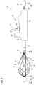
- FIG. 1 is a general view of the basket type grasping forceps of the embodiment.
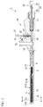
- Fig. 2 is a cross-sectional view of the basket type grasping forceps of the embodiment.
- Fig. 3 is a cross-sectional view taken along line A-A of Fig. 2 .
- the basket type grasping forceps 1 shown in Figs. 1 and 2 is a medical instrument inserted into a conduit line in a body such as a bile duct or the like and configured to remove a foreign substance.
- the basket type grasping forceps 1 includes a sheath 2, a main body section 3 inserted into the sheath 2, and a manipulation section 15 fixed to the sheath 2.
- the sheath 2 is a cylindrical member having flexibility.
- the sheath 2 has an exterior dimension at which it can be inserted to advance or retreat with respect to a treatment tool channel of the endoscope.
- a distal end of the sheath 2 has a hardness such that a basket section 4 (to be described below) can be folded upon use of the basket type grasping forceps 1.
- the main body section 3 is an elongated member inserted into the sheath 2 having a distal end and a proximal end.
- the main body section 3 includes the basket section 4, a first wire 9 connected to the basket section 4, a connecting member 10 configured to connect the basket section 4 and the first wire 9, a removal mechanism 11 configured to remove a foreign substance in the basket section 4, and a center wire 14 fixed to the basket section 4.
- the basket section 4 which is expandable and contractible, is disposed at a distal end side of the main body section 3 and spread in a substantially fusiform shape to hold a foreign substance.
- the basket section 4 in a contracted state has a substantially linear shape that can be accommodated in the sheath 2.
- the basket section 4 includes a plurality of basket wires 5, and a fixing member 6 configured to fix the plurality of basket wires 5 and form a basket section in a substantially fusiform shape.
- the basket section 4 has a substantially fusiform shape and holds a foreign substance in the body therein (see Fig. 4 ).
- the plurality of basket wires 5 are provided such that the basket section 4 is formed in a substantially fusiform shape.
- the basket wires 5 form a helical shape about a centerline of the basket section 4.
- the basket wires 5 have a denser helical pitch closer to the distal side. That is, sizes of openings formed by the plurality of basket wires 5 are smallest at the distal end of the basket section 4 and gradually increase toward the proximal side of the basket section 4.
- the fixing member 6 has a distal fixing member 7 configured to bind the basket wires 5 and fix them to the distal side of the basket section 4, and a proximal fixing member 8 configured to bind the basket wires 5 and fix them to the proximal side of the basket section 4. Both of the distal fixing member 7 and the proximal fixing member 8 form a cylindrical shape.
- All of the basket wires 5 are inserted into the distal fixing member 7 and the proximal fixing member 8.
- the distal fixing member 7 and the basket wires 5 are fixed by a known fixing method such as adhesion, brazing, soldering, welding, or the like.
- the proximal fixing member 8 and the basket wires 5 are fixed by a known fixing method such as adhesion, brazing, soldering, welding, or the like.
- the first wire 9 is disposed at the proximal side of the basket section 4 and fixed to the basket section 4 by the connecting member 10.
- a distal end of the first wire 9 is inserted into the connecting member 10, and simultaneously, proximal ends of the basket wires 5 of the basket section 4 are inserted into the connecting member 10.
- the distal end of the first wire 9 and the connecting member 10 are fixed by a known fixing method such as adhesion, brazing, soldering, welding, or the like.
- the proximal end of the basket wires 5 and the connecting member 10 are fixed by a known fixing method such as adhesion, brazing, soldering, welding, or the like.
- the removal mechanism 11 shown in Fig. 1 is installed to move the foreign substance in the basket section 4 from the distal side toward the proximal side of the basket section 4.
- the removal mechanism 11 includes a slide sleeve 12 attached to the basket section 4, and a second wire 13 fixed to the slide sleeve 12.
- the slide sleeve 12 is a cylindrical member into which the plurality of basket wires 5 are inserted, and is able to advance or retreat with respect to the plurality of basket wires 5. All of the basket wires 5 are inserted into the slide sleeve 12.
- the slide sleeve 12 is disposed at the distal end of the basket section 4 in a state in which the plurality of basket wires 5 are spread to form a substantially fusiform shape.
- the second wire 13 is a wire-shaped member configured to advance or retract the slide sleeve 12 with respect to the basket wires 5.
- the distal end of the second wire 13 is fixed to the slide sleeve 12.
- the second wire 13 extends to the proximal side through the basket section 4 to be directed from the slide sleeve 12 to the sheath 2. Further, in the embodiment, the second wire 13 extends to the manipulation section 15 through the sheath 2. A second wire manipulation mechanism 37 is attached to the proximal end of the second wire 13.
- the center wire 14 is fixed to the distal end of the basket section 4 and extends to at least the proximal end of the basket section 4 through substantially a center of the basket section 4. In the embodiment, the center wire 14 is fixed to the inside of the distal fixing member 7 of the basket section 4 together with the basket wires 5.
- the proximal end of the center wire 14 extends closer to the proximal side than the opening of the distal end side of the sheath 2, and even in a state in which the basket section 4 is completely exposed from the opening of the distal end of the sheath 2 in a conventional use state of the basket type grasping forceps 1, the proximal end of the center wire 14 is formed not to exit the opening of the distal end side of the sheath 2.
- the manipulation section 15 is fixed to the proximal end of the sheath 2 to advance or retract the first wire 9 and the second wire 13 with respect to the sheath 2.
- the manipulation section 15 includes a manipulation main body 16, a slider 24 and the second wire manipulation mechanism 37.
- the manipulation main body 16 is fixed to the proximal end of the sheath 2.
- the manipulation main body 16 has a first port 17 through which a portion of the slider 24 configured to advance and retract the first wire 9 is inserted, and a second port 19 through which the second wire 13 is inserted.
- the first port 17 has an O-ring 18 that can be adhered to an outer surface of a shaft 25 (to be described below). Accordingly, the first port 17 and the shaft 25 are able to advance and retreat in a water-tight state.
- the second port 19 has an opening section 20 in communication with the sheath 2, a stopper 21 having elasticity and disposed in the opening section 20, and a screw body 22 screwed into the opening section 20 of the second port 19 and configured to elastically deform the stopper 21.
- the screw body 22 is screwed into the opening section 20, when the stopper 21 is elastically deformed to be adhered to an outer circumferential surface of the second wire 13, the second wire 13 is fixed to the manipulation section 15.
- the stopper 21 When the stopper 21 is elastically deformed to be adhered to the outer circumferential surface of the second wire 13, the second port 19 is water-tightly closed.
- a third port 23 is a port configured to deliver a liquid such as a contrast medium, rinse water, or the like, and can be water-tightly connected to, for example, a syringe.
- the liquid When the liquid is injected from the third port 23 while the first port 17 and the second port 19 are in the water-tight state, the liquid flows into the sheath 2 to be ejected from an opening of the distal end side of the sheath 2.
- the slider 24 has the shaft 25 fixed to the proximal end of the first wire 9, and a grip 27 disposed at the proximal end of the shaft 25.
- the shaft 25 is a hard member, and has a cylindrical shape in the embodiment.
- the first wire 9 and the shaft 25 are connected via a connecting pipe 26.
- the proximal end of the first wire 9 is inserted into the connecting pipe 26 and fixed by a known fixing method such as adhesion, brazing, soldering, welding, or the like.
- the distal end of the shaft 25 is inserted into the connecting pipe 26 and fixed by a known fixing method such as adhesion, brazing, soldering, welding, or the like.
- the grip 27 is a member having an exterior shape larger than that of the shaft 25 such that an operator of the basket type grasping forceps 1 can easily hold the grip 27.
- the grip 27 may have a brace according to necessity.
- the second wire manipulation mechanism 37 is attached to the proximal end of the second wire 13. As the second wire manipulation mechanism 37 is manipulated, the slide sleeve 12 and the second wire 13 can advance and retreat with respect to the plurality of basket wires 5.
- FIGS. 4 and 5 are views for describing the action of the basket type grasping forceps of the embodiment.
- the basket type grasping forceps 1 is inserted into the conduit line such as the bile duct or the like in the body of the patient through the endoscope channel in a state in which the basket section 4 is accommodated in the sheath 2.
- the basket section 4 protrudes from the sheath 2 in the conduit line due to the advance manipulation of the slider 24, the basket section 4 is widened and opened by an elastic force of the basket wires 5.
- the slider 24 can be pulled to reduce a diameter of the basket section 4 and the foreign substance X can be tightly held in the basket section 4.
- the basket type grasping forceps 1 is removed from the body of the patient together with the endoscope, and the foreign substance X is collected.
- the basket section 4 When the foreign substance X held in the basket section 4 is large, the basket section 4 may not be removed from the conduit line such as the bile duct or the like. In order to avoid this, in a state in which the basket section 4 is disposed in the conduit line, the held foreign substance X should be discharged to the outside of the basket.
- the slide sleeve 12 moved from the distal end of the basket section 4 to the proximal side moves the basket wires 5 such that each of the basket wires 5 approaches with each other. That is, as the slide sleeve 12 is moved to the proximal side, a diameter of the basket section 4 is gradually reduced from the distal side to the proximal side.
- the basket type grasping forceps 1 of the embodiment can remove the foreign substance X in the body to the outside of the basket section 4 by moving the slide sleeve 12 from the distal end of the basket section 4 to the proximal side.
- the basket type grasping forceps 1 of the embodiment can easily remove the foreign substance X held in the basket wires 5, and efficiency of treatment can be increased.
- Fig. 6 is a side view showing a configuration of the variant.
- the basket type grasping forceps 1A of the variant does not include the center wire 14.
- the basket type grasping forceps 1A of the variant also exhibits the same effect as the first embodiment.
- Fig. 7 is a side view showing a configuration of the variant.
- a basket type grasping forceps 1C of the variant has a basket section 4A having a different shape from the first embodiment.
- the basket section 4A has a plurality of basket wires 5A in which two element wires are bound at the proximal side and branched off from the intermediate portion toward the distal side one by one.
- the opening is reduced at the distal side and the opening is increased at the proximal side.
- the basket type grasping forceps 1A of the variant also exhibits the same effect as the first embodiment.
- FIG. 8 is a cross-sectional view showing a configuration of the basket type grasping forceps of the embodiment.
- the basket type grasping forceps 1B of the embodiment has a center wire 14A extending to the manipulation section 15, instead of the center wire 14 described in the first embodiment.
- a fourth port 30 is installed at the manipulation section 15.
- the center wire 14A is inserted through the fourth port 30, the proximal end of the center wire 14A is pulled out to the outside of the manipulation section 15, and the center wire manipulation mechanism 38 is attached to the fourth port 30.
- the fourth port 30 installed at the manipulation section 15 of the embodiment includes an opening section 31 through which the center wire 14 is inserted, a stopper 32 constituted by an elastic member formed in the opening section, and a screw body 33 screwed into the opening section 31 to deform the stopper 32.
- the stopper 32 When the screw body 33 in the fourth port 30 is screwed into the opening section 31, the stopper 32 is elastically deformed to come in contact with the outer surface of the center wire 14A, and the opening section 31 is water-tightly closed while the center wire 14A is fixed to the manipulation section 15. Accordingly, the liquid can be delivered from the third port 23 to the distal end of the sheath 2.
- a shape of the basket section 4 can be varied by advancing and retracting the center wire 14A in a longitudinal direction of the sheath 2 in the center wire manipulation mechanism 38.
- FIG. 9 is a cross-sectional view showing a configuration of the embodiment.
- the embodiment is distinguished from the first embodiment in that a slide sleeve 12A having a different shape from that of the slide sleeve 12 described in the first embodiment is provided.
- the slide sleeve 12A installed at the basket type grasping forceps 1D of the embodiment has an inner diameter having a slight clearance with respect to a diameter of a bundle when the basket wires 5 are bound to be closely adhered to each other at the distal side.
- the slide sleeve 12A has an inner diameter at the proximal side larger than an inner diameter of the distal side.
- the slide sleeve 12A of the embodiment has a tapered inner surface 12A1 having an inner diameter that is gradually increased from the distal side to the proximal side.
- a shape of the inner surface of the slide sleeve 12A is not limited to the tapered shape.
- grooves configured to individually guide the basket wires 5 may be formed in the inner surface of the slide sleeve 12A. In this case, the basket wires 5 cannot be easily entangled in the slide sleeve 12A and can smoothly move the slide sleeve 12A with respect to the basket wires 5.
- Fig. 10 is a cross-sectional view showing a configuration of the embodiment.
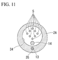
- Fig. 11 is a cross-sectional view taken along line B-B of Fig. 10 .
- the basket type grasping forceps IE of the embodiment includes a sheath 2A in which a first lumen 34 through which the first wire 9 and the basket section 4 pass, and a second lumen 35 through which the second wire 13 passes are formed, instead of the sheath 2 described in the first embodiment.
- the center wire 14 is inserted through the first lumen 34 of the sheath 2A together with the first wire 9 and the basket section 4.
- the first port 17 comes in communication with the first lumen 34 and the second port 19 comes in communication with the second lumen 35.
- the second port 19 may not be water-tight since the liquid from the third port 23 does not enter the second port 19.
- the third port 23 may come in contact with the second lumen 35.
- the sheath 2A since the sheath 2A has a plurality of lumens and the first wire 9 and the second wire 13 are inserted into different lumens, the first wire 9 and the second wire 13 are not entangled.
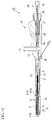
- Fig. 12 is a cross-sectional view showing a configuration of the variant.
- the second wire 13 extends toward the manipulation section 15 outside the sheath 2.
- the manipulation section 15 has a hook 36 configured to hook the second wire 13, instead of the second port 19.
- a means configured to cause the second wire 13 to approach the outer surface of the sheath 2 and hold the second wire 13 may be provided.
- the basket type grasping forceps capable of easily discharging a foreign substance held in the basket to the outside of the basket.
Landscapes
- Health & Medical Sciences (AREA)
- Surgery (AREA)
- Life Sciences & Earth Sciences (AREA)
- Heart & Thoracic Surgery (AREA)
- Nuclear Medicine, Radiotherapy & Molecular Imaging (AREA)
- Vascular Medicine (AREA)
- Engineering & Computer Science (AREA)
- Biomedical Technology (AREA)
- Orthopedic Medicine & Surgery (AREA)
- Medical Informatics (AREA)
- Molecular Biology (AREA)
- Animal Behavior & Ethology (AREA)
- General Health & Medical Sciences (AREA)
- Public Health (AREA)
- Veterinary Medicine (AREA)
- Surgical Instruments (AREA)
Abstract
Description
- The present invention relates to a basket type grasping forceps.
- Priority is claimed on Japanese Patent Application No.
2013-233973, filed November 12, 2013 - In the related art, a basket type grasping forceps inserted into a conduit line in a body such as a bile duct or the like and configured to collect a foreign substance such as a calculus or the like is known (for example, see
Patent Documents - Since the basket type grasping forceps has a structure for holding a foreign substance using a plurality of wires, when a large amount of a foreign substance should be collected, a basket may not be removed from the conduit line while holding the foreign substance. For example, when the foreign substance is not removed from between the plurality of wires disclosed in
Patent Documents -
- [Patent Document 1] Japanese Unexamined Patent Application, First Publication No.
H11-114070 - [Patent Document 2] Japanese Unexamined Patent Application, First Publication No.
2006-94876 - [Patent Document 3] International Publication No. PCT/2012/141213
- When a large foreign substance is held, if the basket cannot be removed from the conduit line such as the bile duct or the like together with the foreign substance, the foreign substance that is held at once should be discharged from the basket in the conduit line and it is necessary to remove just the basket type grasping forceps only. However, in such a case, since the foreign substance is large, if the foreign substance is held at once, the foreign substance cannot be discharged to the outside of the basket in the conduit line as intended, and complicated operations are required.
- In consideration of the above-mentioned circumstances, the present invention is directed to provide a basket type grasping forceps capable of easily removing a foreign substance held in a basket.
- A basket type grasping forceps of a first aspect of the present invention a sheath, a main body section which has a distal end and a proximal end and inserted through the sheath; and a manipulation section which is fixed to the sheath and to which the proximal end of the main body section is attached. The main body section includes a basket section which is provided at a distal side of the main body section, which has a substantially fusiform shape, and which is configured to hold a foreign substance, a first wire which is provided at a proximal side of the basket section and which is fixed to the basket section, and a removal mechanism which is attached to the basket section and which moves the foreign substance in the basket section. The basket section includes a plurality of basket wires; and a fixing member which binds and fixes the plurality of basket wires. The removal mechanism includes a slide sleeve which is provided at the distal side of the basket section, through which the plurality of basket wires are inserted, and which is configured to advance and retract with respect to the plurality of basket wires, and a second wire which has a distal end fixed to the slide sleeve and which is configured to advance and retract the slide sleeve with respect to the basket wires.
- According to a second aspect of the present invention, in the basket type grasping forceps of the first aspect, a size of an opening at the proximal side of the basket section which is formed by the plurality of basket wires may be larger than a size of the opening at the distal side of the basket section which is formed by the pluarlity of basket wires.
- According to a third aspect of the present invention, in the basket type grasping forceps of the second aspect, the main body section may further have a center wire, and the center wire may be fixed to the distal end of the basket section, pass substantially a center of the basket section, and extend to at least the proximal end of the basket section.
- According to a fourth aspect of the present invention, in the basket type grasping forceps of the third aspect, the slide sleeve may be provided to be positioned at the distal end of the basket section in a state in which the foreign substance is held in the basket section that is spread to form the substantially fusiform shape.
- According to a fifth aspect of the present invention, in the basket type grasping forceps of the fourth aspect, the second wire may extend from the slide sleeve to the proximal side through the basket section.
- According to a sixth aspect of the present invention, in the basket type grasping forceps of the fifth aspect, a lumen may be formed at the slide sleeve and the plurality of basket wires and the center wire may be inserted into the lumen.
- According to the above-mentioned aspects, it is possible to provide the basket type grasping forceps capable of easily discharging a foreign substance held in the basket to the outside of the basket.
-
-
Fig. 1 is a general view of a basket type grasping forceps of a first embodiment of the present invention. -
Fig. 2 is a cross-sectional view of the basket type grasping forceps of the embodiment. -
Fig. 3 is a cross-sectional view taken along line A-A ofFig. 2 . -
Fig. 4 is a view for describing an action of the basket type grasping forceps of the embodiment. -
Fig. 5 is a view for describing an action of the basket type grasping forceps of the embodiment. -
Fig. 6 is a side view showing a configuration of a variant of the embodiment. -
Fig. 7 is a side view showing a configuration of another variant of the embodiment. -
Fig. 8 is a cross-sectional view showing a basket type grasping forceps of a second embodiment of the present invention. -
Fig. 9 is a cross-sectional view showing a basket type grasping forceps of a third embodiment of the present invention. -
Fig. 10 is a cross-sectional view showing a basket type grasping forceps of a fourth embodiment of the present invention. -
Fig. 11 is a cross-sectional view taken along line B-B ofFig. 10 . -
Fig. 12 is a cross-sectional view showing a configuration of the variant of the embodiment. - A basket type grasping forceps of a first embodiment of the present invention will be described.
Fig. 1 is a general view of the basket type grasping forceps of the embodiment.Fig. 2 is a cross-sectional view of the basket type grasping forceps of the embodiment.Fig. 3 is a cross-sectional view taken along line A-A ofFig. 2 . - The basket
type grasping forceps 1 shown inFigs. 1 and2 is a medical instrument inserted into a conduit line in a body such as a bile duct or the like and configured to remove a foreign substance. - As shown in
Fig. 1 , the baskettype grasping forceps 1 includes asheath 2, amain body section 3 inserted into thesheath 2, and amanipulation section 15 fixed to thesheath 2. - The
sheath 2 is a cylindrical member having flexibility. Thesheath 2 has an exterior dimension at which it can be inserted to advance or retreat with respect to a treatment tool channel of the endoscope. A distal end of thesheath 2 has a hardness such that a basket section 4 (to be described below) can be folded upon use of the baskettype grasping forceps 1. - As shown in
Fig. 2 , themain body section 3 is an elongated member inserted into thesheath 2 having a distal end and a proximal end. Themain body section 3 includes thebasket section 4, afirst wire 9 connected to thebasket section 4, a connectingmember 10 configured to connect thebasket section 4 and thefirst wire 9, aremoval mechanism 11 configured to remove a foreign substance in thebasket section 4, and acenter wire 14 fixed to thebasket section 4. - As shown in
Figs. 1 and2 , thebasket section 4, which is expandable and contractible, is disposed at a distal end side of themain body section 3 and spread in a substantially fusiform shape to hold a foreign substance. Thebasket section 4 in a contracted state has a substantially linear shape that can be accommodated in thesheath 2. - The
basket section 4 includes a plurality ofbasket wires 5, and afixing member 6 configured to fix the plurality ofbasket wires 5 and form a basket section in a substantially fusiform shape. - The
basket section 4 has a substantially fusiform shape and holds a foreign substance in the body therein (seeFig. 4 ). The plurality ofbasket wires 5 are provided such that thebasket section 4 is formed in a substantially fusiform shape. - In the embodiment, the
basket wires 5 form a helical shape about a centerline of thebasket section 4. Thebasket wires 5 have a denser helical pitch closer to the distal side. That is, sizes of openings formed by the plurality ofbasket wires 5 are smallest at the distal end of thebasket section 4 and gradually increase toward the proximal side of thebasket section 4. - As shown in
Fig. 1 , thefixing member 6 has adistal fixing member 7 configured to bind thebasket wires 5 and fix them to the distal side of thebasket section 4, and aproximal fixing member 8 configured to bind thebasket wires 5 and fix them to the proximal side of thebasket section 4. Both of thedistal fixing member 7 and theproximal fixing member 8 form a cylindrical shape. - All of the
basket wires 5 are inserted into thedistal fixing member 7 and theproximal fixing member 8. Thedistal fixing member 7 and thebasket wires 5 are fixed by a known fixing method such as adhesion, brazing, soldering, welding, or the like. Similarly, the proximal fixingmember 8 and thebasket wires 5 are fixed by a known fixing method such as adhesion, brazing, soldering, welding, or the like. - As shown in
Fig. 2 , thefirst wire 9 is disposed at the proximal side of thebasket section 4 and fixed to thebasket section 4 by the connectingmember 10. - As shown in
Fig. 2 , a distal end of thefirst wire 9 is inserted into the connectingmember 10, and simultaneously, proximal ends of thebasket wires 5 of thebasket section 4 are inserted into the connectingmember 10. The distal end of thefirst wire 9 and the connectingmember 10 are fixed by a known fixing method such as adhesion, brazing, soldering, welding, or the like. Similarly, the proximal end of thebasket wires 5 and the connectingmember 10 are fixed by a known fixing method such as adhesion, brazing, soldering, welding, or the like. - The
removal mechanism 11 shown inFig. 1 is installed to move the foreign substance in thebasket section 4 from the distal side toward the proximal side of thebasket section 4. - As shown in
Figs. 1 and2 , theremoval mechanism 11 includes aslide sleeve 12 attached to thebasket section 4, and asecond wire 13 fixed to theslide sleeve 12. - The
slide sleeve 12 is a cylindrical member into which the plurality ofbasket wires 5 are inserted, and is able to advance or retreat with respect to the plurality ofbasket wires 5. All of thebasket wires 5 are inserted into theslide sleeve 12. Theslide sleeve 12 is disposed at the distal end of thebasket section 4 in a state in which the plurality ofbasket wires 5 are spread to form a substantially fusiform shape. - The
second wire 13 is a wire-shaped member configured to advance or retract theslide sleeve 12 with respect to thebasket wires 5. The distal end of thesecond wire 13 is fixed to theslide sleeve 12. - In a state in which the
basket section 4 forms a substantially fusiform shape, thesecond wire 13 extends to the proximal side through thebasket section 4 to be directed from theslide sleeve 12 to thesheath 2. Further, in the embodiment, thesecond wire 13 extends to themanipulation section 15 through thesheath 2. A secondwire manipulation mechanism 37 is attached to the proximal end of thesecond wire 13. - The
center wire 14 is fixed to the distal end of thebasket section 4 and extends to at least the proximal end of thebasket section 4 through substantially a center of thebasket section 4. In the embodiment, thecenter wire 14 is fixed to the inside of thedistal fixing member 7 of thebasket section 4 together with thebasket wires 5. - In the embodiment, the proximal end of the
center wire 14 extends closer to the proximal side than the opening of the distal end side of thesheath 2, and even in a state in which thebasket section 4 is completely exposed from the opening of the distal end of thesheath 2 in a conventional use state of the baskettype grasping forceps 1, the proximal end of thecenter wire 14 is formed not to exit the opening of the distal end side of thesheath 2. - As shown in
Figs. 1 and2 , themanipulation section 15 is fixed to the proximal end of thesheath 2 to advance or retract thefirst wire 9 and thesecond wire 13 with respect to thesheath 2. - The
manipulation section 15 includes a manipulationmain body 16, aslider 24 and the secondwire manipulation mechanism 37. - The manipulation
main body 16 is fixed to the proximal end of thesheath 2. The manipulationmain body 16 has afirst port 17 through which a portion of theslider 24 configured to advance and retract thefirst wire 9 is inserted, and asecond port 19 through which thesecond wire 13 is inserted. - The
first port 17 has an O-ring 18 that can be adhered to an outer surface of a shaft 25 (to be described below). Accordingly, thefirst port 17 and theshaft 25 are able to advance and retreat in a water-tight state. - The
second port 19 has anopening section 20 in communication with thesheath 2, astopper 21 having elasticity and disposed in theopening section 20, and ascrew body 22 screwed into theopening section 20 of thesecond port 19 and configured to elastically deform thestopper 21. As thescrew body 22 is screwed into theopening section 20, when thestopper 21 is elastically deformed to be adhered to an outer circumferential surface of thesecond wire 13, thesecond wire 13 is fixed to themanipulation section 15. - When the
stopper 21 is elastically deformed to be adhered to the outer circumferential surface of thesecond wire 13, thesecond port 19 is water-tightly closed. - A
third port 23 is a port configured to deliver a liquid such as a contrast medium, rinse water, or the like, and can be water-tightly connected to, for example, a syringe. - When the liquid is injected from the
third port 23 while thefirst port 17 and thesecond port 19 are in the water-tight state, the liquid flows into thesheath 2 to be ejected from an opening of the distal end side of thesheath 2. - The
slider 24 has theshaft 25 fixed to the proximal end of thefirst wire 9, and agrip 27 disposed at the proximal end of theshaft 25. - The
shaft 25 is a hard member, and has a cylindrical shape in the embodiment. Thefirst wire 9 and theshaft 25 are connected via a connectingpipe 26. In the embodiment, the proximal end of thefirst wire 9 is inserted into the connectingpipe 26 and fixed by a known fixing method such as adhesion, brazing, soldering, welding, or the like. Similarly, the distal end of theshaft 25 is inserted into the connectingpipe 26 and fixed by a known fixing method such as adhesion, brazing, soldering, welding, or the like. - The
grip 27 is a member having an exterior shape larger than that of theshaft 25 such that an operator of the baskettype grasping forceps 1 can easily hold thegrip 27. Thegrip 27 may have a brace according to necessity. - The second
wire manipulation mechanism 37 is attached to the proximal end of thesecond wire 13. As the secondwire manipulation mechanism 37 is manipulated, theslide sleeve 12 and thesecond wire 13 can advance and retreat with respect to the plurality ofbasket wires 5. - Next, an action of the basket
type grasping forceps 1 of the embodiment will be described.Figs. 4 and5 are views for describing the action of the basket type grasping forceps of the embodiment. - Like the general basket type medical treatment tool, the basket
type grasping forceps 1 is inserted into the conduit line such as the bile duct or the like in the body of the patient through the endoscope channel in a state in which thebasket section 4 is accommodated in thesheath 2. When thebasket section 4 protrudes from thesheath 2 in the conduit line due to the advance manipulation of theslider 24, thebasket section 4 is widened and opened by an elastic force of thebasket wires 5. - After a foreign substance X such as renal calculi or the like is taken into the widened and opened
basket section 4, theslider 24 can be pulled to reduce a diameter of thebasket section 4 and the foreign substance X can be tightly held in thebasket section 4. After that, the baskettype grasping forceps 1 is removed from the body of the patient together with the endoscope, and the foreign substance X is collected. - When the foreign substance X held in the
basket section 4 is large, thebasket section 4 may not be removed from the conduit line such as the bile duct or the like. In order to avoid this, in a state in which thebasket section 4 is disposed in the conduit line, the held foreign substance X should be discharged to the outside of the basket. - As a method of discharging the foreign substance X in the related art, there is a method of introducing an emergency lithotripter, a laser, or the like, into the body and breaking the foreign substance X, or the like. However, these methods in the related art are complicated and increase the entire treatment time.
- In the basket
type grasping forceps 1, when the proximal end of thesecond wire 13 in the secondwire manipulation mechanism 37 shown inFig. 1 is pulled to the proximal side, theslide sleeve 12 disposed at the distal end of thebasket section 4 is pulled to the proximal side. Accordingly, as shown inFig. 5 , theslide sleeve 12 is moved to the proximal side with respect to thebasket section 4. - The
slide sleeve 12 moved from the distal end of thebasket section 4 to the proximal side moves thebasket wires 5 such that each of thebasket wires 5 approaches with each other. That is, as theslide sleeve 12 is moved to the proximal side, a diameter of thebasket section 4 is gradually reduced from the distal side to the proximal side. - When the diameter of the
basket section 4 is gradually reduced from the distal side to the proximal side, in the case in which the foreign substance X in the body is captured by the distal side portion of thebasket section 4, the foreign substance X is moved to the proximal side in thebasket section 4. - When a size of the opening of the distal side of the
basket section 4 of the embodiment is compared with that of the opening of the proximal side, the opening of the proximal side is larger. For this reason, according to a decrease in diameter of thebasket section 4, the foreign substance X moved to the proximal side in thebasket section 4 is discharged to the outside of thebasket section 4 from the gap between thebasket wires 5. - In these points, the basket
type grasping forceps 1 of the embodiment can remove the foreign substance X in the body to the outside of thebasket section 4 by moving theslide sleeve 12 from the distal end of thebasket section 4 to the proximal side. As a result, the baskettype grasping forceps 1 of the embodiment can easily remove the foreign substance X held in thebasket wires 5, and efficiency of treatment can be increased. - Next, a variant of the basket
type grasping forceps 1 of the embodiment will be described.Fig. 6 is a side view showing a configuration of the variant. - As shown in
Fig. 6 , the basket type grasping forceps 1A of the variant does not include thecenter wire 14. - Like the basket
type grasping forceps 1 of the above-mentioned first embodiment, even in the basket type grasping forceps 1A of the variant, as theslide sleeve 12 is moved from the distal end of thebasket section 4 to the proximal side, a diameter of thebasket section 4 is gradually reduced from the distal side to the proximal side. - For this reason, the basket type grasping forceps 1A of the variant also exhibits the same effect as the first embodiment.
- Next, another variant of the basket
type grasping forceps 1 of the first embodiment will be described.Fig. 7 is a side view showing a configuration of the variant. - As shown in
Fig. 7 , a baskettype grasping forceps 1C of the variant has abasket section 4A having a different shape from the first embodiment. - The
basket section 4A has a plurality ofbasket wires 5A in which two element wires are bound at the proximal side and branched off from the intermediate portion toward the distal side one by one. In thebasket section 4A of the variant, as thebasket wires 5A have branches, the opening is reduced at the distal side and the opening is increased at the proximal side. - Even in the basket
type grasping forceps 1C of the variant, similar to the baskettype grasping forceps 1 of the first embodiment, as theslide sleeve 12 is moved from the distal end of thebasket section 4A to the proximal side, a diameter of thebasket section 4A is gradually reduced from the distal side to the proximal side. - For this reason, the basket type grasping forceps 1A of the variant also exhibits the same effect as the first embodiment.
- Next, the basket type grasping forceps of the second embodiment of the present invention will be described.
Fig. 8 is a cross-sectional view showing a configuration of the basket type grasping forceps of the embodiment. - As shown in
Fig. 8 , the baskettype grasping forceps 1B of the embodiment has acenter wire 14A extending to themanipulation section 15, instead of thecenter wire 14 described in the first embodiment. - A
fourth port 30 is installed at themanipulation section 15. Thecenter wire 14A is inserted through thefourth port 30, the proximal end of thecenter wire 14A is pulled out to the outside of themanipulation section 15, and the centerwire manipulation mechanism 38 is attached to thefourth port 30. - The
fourth port 30 installed at themanipulation section 15 of the embodiment includes anopening section 31 through which thecenter wire 14 is inserted, astopper 32 constituted by an elastic member formed in the opening section, and ascrew body 33 screwed into theopening section 31 to deform thestopper 32. - When the
screw body 33 in thefourth port 30 is screwed into theopening section 31, thestopper 32 is elastically deformed to come in contact with the outer surface of thecenter wire 14A, and theopening section 31 is water-tightly closed while thecenter wire 14A is fixed to themanipulation section 15. Accordingly, the liquid can be delivered from thethird port 23 to the distal end of thesheath 2. - In the embodiment, it is possible to manipulate the
center wire 14A by a centerwire manipulation mechanism 38. For this reason, a shape of thebasket section 4 can be varied by advancing and retracting thecenter wire 14A in a longitudinal direction of thesheath 2 in the centerwire manipulation mechanism 38. - Next, a basket type grasping forceps of a third embodiment of the present invention will be described.
Fig. 9 is a cross-sectional view showing a configuration of the embodiment. - As shown in
Fig. 9 , the embodiment is distinguished from the first embodiment in that aslide sleeve 12A having a different shape from that of theslide sleeve 12 described in the first embodiment is provided. - The
slide sleeve 12A installed at the baskettype grasping forceps 1D of the embodiment has an inner diameter having a slight clearance with respect to a diameter of a bundle when thebasket wires 5 are bound to be closely adhered to each other at the distal side. Theslide sleeve 12A has an inner diameter at the proximal side larger than an inner diameter of the distal side. - That is, the
slide sleeve 12A of the embodiment has a tapered inner surface 12A1 having an inner diameter that is gradually increased from the distal side to the proximal side. - In the embodiment, when the
slide sleeve 12A is moved from the distal side to the proximal side of thebasket section 4, a contact angle of the inner surface of theslide sleeve 12A with respect to thebasket wires 5 radially extending from a centerline of theslide sleeve 12A can be reduced. For this reason, theslide sleeve 12A can be smoothly moved to the proximal side with respect to thebasket wires 5. - A shape of the inner surface of the
slide sleeve 12A is not limited to the tapered shape. For example, grooves configured to individually guide thebasket wires 5 may be formed in the inner surface of theslide sleeve 12A. In this case, thebasket wires 5 cannot be easily entangled in theslide sleeve 12A and can smoothly move theslide sleeve 12A with respect to thebasket wires 5. - Next, a basket type grasping forceps of a fourth embodiment of the present invention will be described.
Fig. 10 is a cross-sectional view showing a configuration of the embodiment.Fig. 11 is a cross-sectional view taken along line B-B ofFig. 10 . - As shown in
Figs. 10 and11 , the basket type grasping forceps IE of the embodiment includes asheath 2A in which afirst lumen 34 through which thefirst wire 9 and thebasket section 4 pass, and asecond lumen 35 through which thesecond wire 13 passes are formed, instead of thesheath 2 described in the first embodiment. In the embodiment, thecenter wire 14 is inserted through thefirst lumen 34 of thesheath 2A together with thefirst wire 9 and thebasket section 4. - In the embodiment, in the
manipulation section 15, thefirst port 17 comes in communication with thefirst lumen 34 and thesecond port 19 comes in communication with thesecond lumen 35. In the embodiment, thesecond port 19 may not be water-tight since the liquid from thethird port 23 does not enter thesecond port 19. - In the embodiment, while an example in which the
third port 23 comes in communication with thefirst lumen 34 is provided, thethird port 23 may come in contact with thesecond lumen 35. - Even in the above-mentioned configuration, the same effect as the first embodiment is exhibited.
- In the embodiment, since the
sheath 2A has a plurality of lumens and thefirst wire 9 and thesecond wire 13 are inserted into different lumens, thefirst wire 9 and thesecond wire 13 are not entangled. - Next, another variant of the basket type grasping forceps of the fourth embodiment will be described.
Fig. 12 is a cross-sectional view showing a configuration of the variant. - As shown in
Fig. 12 , in the baskettype grasping forceps 1F of the variant, thesecond wire 13 extends toward themanipulation section 15 outside thesheath 2. Themanipulation section 15 has ahook 36 configured to hook thesecond wire 13, instead of thesecond port 19. - Even in the above-mentioned configuration, the same effect as the fourth embodiment is exhibited.
- In the variant, a means configured to cause the
second wire 13 to approach the outer surface of thesheath 2 and hold thesecond wire 13 may be provided. - While the embodiments and the variants thereof of the present invention have been described above in detail with reference to the accompanying drawings, the specific configuration is not limited to the embodiment but may include design changes without departing from the spirit of the present invention.
- Components shown in the above-mentioned embodiments and variants thereof may be appropriately combined and configured.
- According to the embodiments, it is possible to provide the basket type grasping forceps capable of easily discharging a foreign substance held in the basket to the outside of the basket.
-
- 1, 1A, 1B, 1C, 1D, IE, 1F Basket type grasping forceps
- 2, 2A Sheath
- 3 Main body section
- 4, 4A Basket section
- 5, 5A Basket wires
- 6 Fixing member
- 7 Distal fixing member
- 8 Proximal fixing member
- 9 First wire
- 10 Connecting member
- 11 Removal mechanism
- 12, 12A Slide sleeve
- 12A1 Inner surface of slide sleeve
- 13 Second wire
- 14, 14A Center wire
- 15 Manipulation section
- 16 Manipulation main body
- 17 First port
- 18 O-ring
- 19 Second port
- 20 Opening section
- 21 Stopper
- 22 Screw body
- 23 Third port
- 24 Slider
- 25 Shaft
- 26 Connecting pipe
- 27 Grip
- 30 Fourth port
- 31 Opening section
- 32 Stopper
- 33 Screw body
- 34 First lumen
- 35 Second lumen
- 36 Hook
- 37 Second
wire manipulation mechanism 38 Center wire manipulation mechanism - X Foreign substance
Claims (6)
- A basket type grasping forceps comprising:a sheath;a main body section which has a distal end and a proximal end and inserted through the sheath; anda manipulation section which is fixed to the sheath and to which the proximal end of the main body section is attached,wherein the main body section includes:a basket section which is provided at a distal side of the main body section, which has a substantially fusiform shape, and which is configured to hold a foreign substance;a first wire which is provided at a proximal side of the basket section and which is fixed to the basket section; anda removal mechanism which is attached to the basket section and which moves the foreign substance in the basket section,the basket section includes:a plurality of basket wires; anda fixing member which binds and fixes the plurality of basket wires, andthe removal mechanism includes:a slide sleeve which is provided at the distal side of the basket section, through which the plurality of basket wires are inserted, and which is configured to advance and retract with respect to the plurality of basket wires; anda second wire which has a distal end fixed to the slide sleeve and which is configured to advance and retract the slide sleeve with respect to the basket wires.
- The basket type grasping forceps according to claim 1,
wherein a size of an opening at the proximal side of the basket section which is formed by the plurality of basket wires is larger than a size of an opening at the distal side of the basket section which is formed by the plurality of basket wires. - The basket type grasping forceps according to claim 2, the main body section further comprising: a center wire,
wherein the center wire is fixed to the distal end of the basket section, passes substantially a center of the basket section, and extends to at least the proximal end of the basket section. - The basket type grasping forceps according to claim 3,
wherein the slide sleeve is provided to be positioned at the distal end of the basket section in a state in which the foreign substance is held in the basket section that is spread to form the substantially fusiform shape. - The basket type grasping forceps according to claim 4, wherein the second wire extends from the slide sleeve to the proximal side through the basket section.
- The basket type grasping forceps according to claim 5, wherein a lumen is formed at the slide sleeve and the plurality of basket wires and the center wire are inserted into the lumen.
Applications Claiming Priority (2)
| Application Number | Priority Date | Filing Date | Title |
|---|---|---|---|
| JP2013233973 | 2013-11-12 | ||
| PCT/JP2014/079501 WO2015072394A1 (en) | 2013-11-12 | 2014-11-06 | Basket-type grasping forceps |
Publications (2)
| Publication Number | Publication Date |
|---|---|
| EP3069668A1 true EP3069668A1 (en) | 2016-09-21 |
| EP3069668A4 EP3069668A4 (en) | 2017-06-28 |
Family
ID=53057329
Family Applications (1)
| Application Number | Title | Priority Date | Filing Date |
|---|---|---|---|
| EP14862482.8A Withdrawn EP3069668A4 (en) | 2013-11-12 | 2014-11-06 | Basket-type grasping forceps |
Country Status (5)
| Country | Link |
|---|---|
| US (1) | US9522013B2 (en) |
| EP (1) | EP3069668A4 (en) |
| JP (1) | JP5933842B2 (en) |
| CN (1) | CN105873527B (en) |
| WO (1) | WO2015072394A1 (en) |
Cited By (1)
| Publication number | Priority date | Publication date | Assignee | Title |
|---|---|---|---|---|
| US10932801B2 (en) | 2016-05-26 | 2021-03-02 | Olympus Corporation | Endoscope treatment tool |
Families Citing this family (9)
| Publication number | Priority date | Publication date | Assignee | Title |
|---|---|---|---|---|
| CN105852933B (en) * | 2016-04-27 | 2019-07-26 | 中国人民解放军第二军医大学 | A braided ureteral stone blocking extractor |
| CN106420004A (en) * | 2016-08-08 | 2017-02-22 | 佛山市迪华科技有限公司 | Easy operating stone removal basket |
| WO2019083757A1 (en) * | 2017-10-26 | 2019-05-02 | Teleflex Innovations S.A.R.L. | Subintimal catheter device and assembly |
| JP7016252B2 (en) * | 2017-12-18 | 2022-02-04 | 真 小林 | Basket-type endoscope treatment tool |
| CN109363747A (en) * | 2018-12-20 | 2019-02-22 | 王欣 | A kind of airway wall intervention traction attachment |
| USD943743S1 (en) | 2019-01-15 | 2022-02-15 | Olympus Corporation | Stone retrieval basket for medical device |
| US11534189B2 (en) | 2019-03-01 | 2022-12-27 | Gyrus Acmi, Inc. | Surgical basket |
| WO2025089076A1 (en) * | 2023-10-23 | 2025-05-01 | 朝日インテック株式会社 | Medical device |
| WO2026024329A1 (en) * | 2024-07-25 | 2026-01-29 | Flow Medical Solutions, Inc. | Self-expanding scaffold structures for thrombectomy and/or thrombolysis catheter systems, devices and methods |
Family Cites Families (9)
| Publication number | Priority date | Publication date | Assignee | Title |
|---|---|---|---|---|
| JP2000507856A (en) * | 1996-03-25 | 2000-06-27 | セイフ コンダクト アクチボラゲット | Tissue extraction equipment |
| US6096053A (en) * | 1996-05-03 | 2000-08-01 | Scimed Life Systems, Inc. | Medical retrieval basket |
| JPH1147141A (en) * | 1997-08-04 | 1999-02-23 | Olympus Optical Co Ltd | Gripping instrument for recovering foreign matter in body cavity |
| JP3995770B2 (en) | 1997-10-08 | 2007-10-24 | ペンタックス株式会社 | Endoscope indwelling basket |
| US7410490B2 (en) * | 2000-11-15 | 2008-08-12 | Omnitech Systems, Inc. | Surgical device |
| US20050283166A1 (en) * | 2004-06-17 | 2005-12-22 | Secant Medical, Llc | Expandible snare |
| JP4324535B2 (en) | 2004-09-28 | 2009-09-02 | 朝日インテック株式会社 | Medical treatment tool |
| WO2010102307A1 (en) * | 2009-03-06 | 2010-09-10 | Lazarus Effect, Inc. | Retrieval systems and methods for use thereof |
| JP5252606B2 (en) | 2011-04-13 | 2013-07-31 | オリンパスメディカルシステムズ株式会社 | Endoscopic treatment tool |
-
2014
- 2014-11-06 CN CN201480060962.4A patent/CN105873527B/en active Active
- 2014-11-06 EP EP14862482.8A patent/EP3069668A4/en not_active Withdrawn
- 2014-11-06 JP JP2015526427A patent/JP5933842B2/en active Active
- 2014-11-06 WO PCT/JP2014/079501 patent/WO2015072394A1/en not_active Ceased
-
2016
- 2016-05-03 US US15/145,011 patent/US9522013B2/en active Active
Cited By (1)
| Publication number | Priority date | Publication date | Assignee | Title |
|---|---|---|---|---|
| US10932801B2 (en) | 2016-05-26 | 2021-03-02 | Olympus Corporation | Endoscope treatment tool |
Also Published As
| Publication number | Publication date |
|---|---|
| WO2015072394A1 (en) | 2015-05-21 |
| JPWO2015072394A1 (en) | 2017-03-16 |
| EP3069668A4 (en) | 2017-06-28 |
| CN105873527B (en) | 2018-10-02 |
| JP5933842B2 (en) | 2016-06-15 |
| CN105873527A (en) | 2016-08-17 |
| US20160242795A1 (en) | 2016-08-25 |
| US9522013B2 (en) | 2016-12-20 |
Similar Documents
| Publication | Publication Date | Title |
|---|---|---|
| EP3069668A1 (en) | Basket-type grasping forceps | |
| EP3081177B1 (en) | Basket-type grasping forceps | |
| JP5252606B2 (en) | Endoscopic treatment tool | |
| US10561430B2 (en) | Basket type grasping forceps | |
| EP3184058B1 (en) | Tissue grasping device | |
| CN106999193B (en) | Endoscope treatment device | |
| EP3318205A1 (en) | Treatment instrument for endoscope | |
| JP6124782B2 (en) | Basket-type grasping forceps | |
| EP3238641B1 (en) | Medical instrument | |
| EP3466351B1 (en) | Endoscope treatment tool | |
| JPWO2018122907A1 (en) | Basket type treatment tool | |
| CN106535789B (en) | Stone basket type holding pliers | |
| CN107072682A (en) | Disposal Instruments for Endoscopes | |
| JP6734514B2 (en) | Endoscopic treatment tool |
Legal Events
| Date | Code | Title | Description |
|---|---|---|---|
| PUAI | Public reference made under article 153(3) epc to a published international application that has entered the european phase |
Free format text: ORIGINAL CODE: 0009012 |
|
| 17P | Request for examination filed |
Effective date: 20160608 |
|
| AK | Designated contracting states |
Kind code of ref document: A1 Designated state(s): AL AT BE BG CH CY CZ DE DK EE ES FI FR GB GR HR HU IE IS IT LI LT LU LV MC MK MT NL NO PL PT RO RS SE SI SK SM TR |
|
| AX | Request for extension of the european patent |
Extension state: BA ME |
|
| RAP1 | Party data changed (applicant data changed or rights of an application transferred) |
Owner name: OLYMPUS CORPORATION |
|
| RAP1 | Party data changed (applicant data changed or rights of an application transferred) |
Owner name: OLYMPUS CORPORATION |
|
| RAP1 | Party data changed (applicant data changed or rights of an application transferred) |
Owner name: OLYMPUS CORPORATION |
|
| RIN1 | Information on inventor provided before grant (corrected) |
Inventor name: HAYAKAWA, TOMOTAKA Inventor name: IWABUCHI, AKIHISA |
|
| DAX | Request for extension of the european patent (deleted) | ||
| A4 | Supplementary search report drawn up and despatched |
Effective date: 20170530 |
|
| RIC1 | Information provided on ipc code assigned before grant |
Ipc: A61B 17/221 20060101AFI20170523BHEP |
|
| STAA | Information on the status of an ep patent application or granted ep patent |
Free format text: STATUS: REQUEST FOR EXAMINATION WAS MADE |
|
| STAA | Information on the status of an ep patent application or granted ep patent |
Free format text: STATUS: THE APPLICATION IS DEEMED TO BE WITHDRAWN |
|
| 18D | Application deemed to be withdrawn |
Effective date: 20200603 |