EP3069663A1 - Connecting end effectors to surgical devices - Google Patents
Connecting end effectors to surgical devices Download PDFInfo
- Publication number
- EP3069663A1 EP3069663A1 EP16160646.2A EP16160646A EP3069663A1 EP 3069663 A1 EP3069663 A1 EP 3069663A1 EP 16160646 A EP16160646 A EP 16160646A EP 3069663 A1 EP3069663 A1 EP 3069663A1
- Authority
- EP
- European Patent Office
- Prior art keywords
- body portion
- elongated body
- end effector
- outer tube
- distal
- Prior art date
- Legal status (The legal status is an assumption and is not a legal conclusion. Google has not performed a legal analysis and makes no representation as to the accuracy of the status listed.)
- Granted
Links
Images





Classifications
-
- A—HUMAN NECESSITIES
- A61—MEDICAL OR VETERINARY SCIENCE; HYGIENE
- A61B—DIAGNOSIS; SURGERY; IDENTIFICATION
- A61B17/00—Surgical instruments, devices or methods
- A61B17/00234—Surgical instruments, devices or methods for minimally invasive surgery
-
- A—HUMAN NECESSITIES
- A61—MEDICAL OR VETERINARY SCIENCE; HYGIENE
- A61B—DIAGNOSIS; SURGERY; IDENTIFICATION
- A61B17/00—Surgical instruments, devices or methods
- A61B17/56—Surgical instruments or methods for treatment of bones or joints; Devices specially adapted therefor
- A61B17/58—Surgical instruments or methods for treatment of bones or joints; Devices specially adapted therefor for osteosynthesis, e.g. bone plates, screws or setting implements
- A61B17/88—Osteosynthesis instruments; Methods or means for implanting or extracting internal or external fixation devices
- A61B17/8875—Screwdrivers, spanners or wrenches
- A61B17/8877—Screwdrivers, spanners or wrenches characterised by the cross-section of the driver bit
- A61B17/8883—Screwdrivers, spanners or wrenches characterised by the cross-section of the driver bit the driver bit acting on the periphery of the screw head
-
- A—HUMAN NECESSITIES
- A61—MEDICAL OR VETERINARY SCIENCE; HYGIENE
- A61B—DIAGNOSIS; SURGERY; IDENTIFICATION
- A61B17/00—Surgical instruments, devices or methods
- A61B17/068—Surgical staplers, e.g. containing multiple staples or clamps
-
- A—HUMAN NECESSITIES
- A61—MEDICAL OR VETERINARY SCIENCE; HYGIENE
- A61B—DIAGNOSIS; SURGERY; IDENTIFICATION
- A61B17/00—Surgical instruments, devices or methods
- A61B17/56—Surgical instruments or methods for treatment of bones or joints; Devices specially adapted therefor
- A61B17/58—Surgical instruments or methods for treatment of bones or joints; Devices specially adapted therefor for osteosynthesis, e.g. bone plates, screws or setting implements
- A61B17/88—Osteosynthesis instruments; Methods or means for implanting or extracting internal or external fixation devices
- A61B17/8872—Instruments for putting said fixation devices against or away from the bone
-
- A—HUMAN NECESSITIES
- A61—MEDICAL OR VETERINARY SCIENCE; HYGIENE
- A61B—DIAGNOSIS; SURGERY; IDENTIFICATION
- A61B17/00—Surgical instruments, devices or methods
- A61B2017/00367—Details of actuation of instruments, e.g. relations between pushing buttons, or the like, and activation of the tool, working tip, or the like
-
- A—HUMAN NECESSITIES
- A61—MEDICAL OR VETERINARY SCIENCE; HYGIENE
- A61B—DIAGNOSIS; SURGERY; IDENTIFICATION
- A61B17/00—Surgical instruments, devices or methods
- A61B2017/0046—Surgical instruments, devices or methods with a releasable handle; with handle and operating part separable
- A61B2017/00473—Distal part, e.g. tip or head
-
- A—HUMAN NECESSITIES
- A61—MEDICAL OR VETERINARY SCIENCE; HYGIENE
- A61B—DIAGNOSIS; SURGERY; IDENTIFICATION
- A61B17/00—Surgical instruments, devices or methods
- A61B2017/00477—Coupling
-
- A—HUMAN NECESSITIES
- A61—MEDICAL OR VETERINARY SCIENCE; HYGIENE
- A61B—DIAGNOSIS; SURGERY; IDENTIFICATION
- A61B17/00—Surgical instruments, devices or methods
- A61B17/064—Surgical staples, i.e. penetrating the tissue
- A61B2017/0647—Surgical staples, i.e. penetrating the tissue having one single leg, e.g. tacks
- A61B2017/0648—Surgical staples, i.e. penetrating the tissue having one single leg, e.g. tacks threaded, e.g. tacks with a screw thread
-
- A—HUMAN NECESSITIES
- A61—MEDICAL OR VETERINARY SCIENCE; HYGIENE
- A61B—DIAGNOSIS; SURGERY; IDENTIFICATION
- A61B17/00—Surgical instruments, devices or methods
- A61B17/064—Surgical staples, i.e. penetrating the tissue
- A61B2017/0649—Coils or spirals
-
- A—HUMAN NECESSITIES
- A61—MEDICAL OR VETERINARY SCIENCE; HYGIENE
- A61B—DIAGNOSIS; SURGERY; IDENTIFICATION
- A61B17/00—Surgical instruments, devices or methods
- A61B17/28—Surgical forceps
- A61B17/29—Forceps for use in minimally invasive surgery
- A61B17/2909—Handles
- A61B2017/2912—Handles transmission of forces to actuating rod or piston
- A61B2017/2923—Toothed members, e.g. rack and pinion
-
- A—HUMAN NECESSITIES
- A61—MEDICAL OR VETERINARY SCIENCE; HYGIENE
- A61B—DIAGNOSIS; SURGERY; IDENTIFICATION
- A61B17/00—Surgical instruments, devices or methods
- A61B17/28—Surgical forceps
- A61B17/29—Forceps for use in minimally invasive surgery
- A61B2017/2946—Locking means
-
- A—HUMAN NECESSITIES
- A61—MEDICAL OR VETERINARY SCIENCE; HYGIENE
- A61B—DIAGNOSIS; SURGERY; IDENTIFICATION
- A61B90/00—Instruments, implements or accessories specially adapted for surgery or diagnosis and not covered by any of the groups A61B1/00 - A61B50/00, e.g. for luxation treatment or for protecting wound edges
- A61B90/03—Automatic limiting or abutting means, e.g. for safety
- A61B2090/038—Automatic limiting or abutting means, e.g. for safety during shipment
-
- A—HUMAN NECESSITIES
- A61—MEDICAL OR VETERINARY SCIENCE; HYGIENE
- A61B—DIAGNOSIS; SURGERY; IDENTIFICATION
- A61B2560/00—Constructional details of operational features of apparatus; Accessories for medical measuring apparatus
- A61B2560/04—Constructional details of apparatus
-
- A—HUMAN NECESSITIES
- A61—MEDICAL OR VETERINARY SCIENCE; HYGIENE
- A61B—DIAGNOSIS; SURGERY; IDENTIFICATION
- A61B2560/00—Constructional details of operational features of apparatus; Accessories for medical measuring apparatus
- A61B2560/04—Constructional details of apparatus
- A61B2560/0456—Apparatus provided with a docking unit
Definitions
- the present disclosure relates to surgical devices, systems, and/or methods for performing surgical procedures. More specifically, the present disclosure relates to surgical fastener applying devices and/or systems that are loadable with end effectors containing absorbable or permanent surgical fasteners for performing minimally invasive surgical procedures, and methods of use thereof.
- hernia repair it is often desirable to fasten a mesh to body tissue.
- hernias such as direct or indirect inguinal hernias
- a part of the intestine protrudes through a defect in the abdominal wall to form a hernial sac.
- the defect may be repaired using an open surgery procedure in which a relatively large incision is made and the hernia is closed outside the abdominal wall by suturing.
- the mesh is attached with sutures over the opening in the abdominal wall to provide reinforcement.
- Laparoscopic and endoscopic procedures are currently available to repair a hernia.
- laparoscopic procedures surgery is performed in the abdomen through a small incision while in endoscopic procedures, surgery is performed through narrow endoscopic tubes or cannulas inserted through small incisions in the body.
- Laparoscopic and endoscopic procedures generally utilize long and narrow devices capable of reaching remote regions within the body and are configured to form a seal with the incision or tube they are inserted through. Additionally, the devices are typically capable of being actuated remotely, that is, from outside the body.
- surgical fasteners e.g., surgical tacks, staples, and clips
- Surgical fasteners are often applied through an elongated device for delivery to the mesh, and are manipulated from outside a body cavity.
- the minimally invasive devices include end effectors that are typically loaded with either permanent fasteners or bioabsorbable fasteners. Additionally, following a surgical procedure, these devices are either re-sterilized for re-use or are disposed.
- the present disclosure is directed to new devices, systems, and/or methods for enabling attachment and/or detachment of end effectors to surgical devices and/or systems within small work spaces (e.g., 0.218 inch work envelope or the like).
- the new devices, systems, and/or methods advantageously enable a user to effectuate such attachment and/or detachment remotely from handles thereof by virtue a selectively movable and/or floating detent that couples a proximally extending drive shaft of the end effector to an inner shaft assembly of an elongated body portion of the presently disclosed devices and/or systems.
- a user can articulate the end effectors relative to the presently disclosed devices and/or systems and/or fire anchors from these end effectors, for example, to secure a mesh to body tissue.
- a surgical device in one aspect of the present disclosure, includes an elongated body portion, an end effector, and a detent.
- the elongated body portion includes an outer tube and an inner shaft assembly.
- the outer tube includes a proximal portion and a distal portion.
- the inner shaft assembly is longitudinally and/or rotationally movable through the outer tube.
- the inner shaft assembly includes a distal tube defining a non-circular bore in a distal end thereof. The bore may have a D-shaped cross-sectional profile.
- the outer tube and the distal tube define corresponding openings extending transversely therethrough.
- the inner shaft assembly includes a proximal rigid portion connected to a distal flexible portion. The distal flexible portion extends distally to the distal tube.
- the end effector is selectively connectable to the elongated body portion.
- the end effector includes a drive shaft that extends proximally therefrom and that defines an annular recess in an outer surface thereof.
- the annular recess of the drive shaft may have an arcuate cross-sectional profile.
- the annular recess of the drive shaft may partially circumscribe the drive shaft.
- the drive shaft has a non-circular transverse cross-sectional profile that is complimentary in shape to the non-circular bore of the inner shaft assembly of the elongated body portion.
- the non-circular transverse cross-sectional profile of the drive shaft may be D-shaped and may be complementary to D-shaped cross-sectional profile of the bore.
- the drive shaft rotates in response to rotation of the inner shaft assembly.
- the end effector includes an outer housing positioned about the drive shaft.
- the outer housing of the end effector and the outer tube of the elongated body portion include corresponding mating structures configured and dimensioned for engagement to rotationally align and lock together the elongated body portion and the end effector.
- the detent is movable within the openings of the elongated body portion.
- the detent is positionable between the annular recess of the drive shaft and the outer tube of the elongated body portion to connect the end effector to the elongated body portion in response to insertion of the drive shaft into the non-circular bore of the inner shaft assembly.
- the detent is configured and dimensioned to float between the end effector and the elongated body portion to enable to selective connection between the end effector and the elongated body portion.
- the detent has a spherical shape.
- the surgical device includes an articulation assembly having an articulation actuator supported at a proximal end of the elongated body portion.
- a drive assembly is operatively coupled between the articulation actuator and the distal portion of the outer tube.
- the articulation actuator is actuatable to articulate the distal portion of the outer tube relative to the proximal portion of the outer tube for articulating the end effector relative to a longitudinal axis defined through the elongated body portion.
- the drive assembly may include a slidable tube and an articulation arm.
- the articulation arm is pivotally coupled to the slidable tube and the distal portion of the outer tube.
- the articulation actuator is coupled to the slidable tube so that rotation of the articulation actuator longitudinal translates the slidable tube through the elongated body portion. Longitudinal translation of the slidable tube longitudinally translates the articulation arm to enable the end effector to articulate relative to the longitudinal axis.
- an end effector is configured and dimensioned for releasable connection to an elongated body portion of a surgical fastener applying device.
- the elongated body portion includes a detent.
- the end effector includes a proximally extending drive shaft configured and dimensioned for insertion into the elongated body portion of the surgical fastener applying device.
- the drive shaft defines an annular recess configured and dimensioned to receive the detent such that the detent is positionable between the annular recess and the elongated body portion of the surgical fastener applying device to connect the end effector to the surgical fastener applying device.
- the end effector may include an outer tube supporting the proximally extending drive shaft.
- the drive shaft is rotatable to fire a plurality of fasteners supported within the outer tube from the outer tube.
- a surgical fastener applying device configured and dimensioned for releasable connection to an end effector.
- the surgical fastener applying device includes an elongated body portion and a detent.
- the elongated body portion includes an outer tube and an inner shaft assembly.
- the inner shaft assembly includes a distal tube that defines a non-circular bore in a distal end thereof.
- the inner shaft assembly is longitudinally movable through the outer tube.
- the outer tube and the distal tube define corresponding openings extending transversely therethrough.
- the detent is movable within the openings of the elongated body portion.
- the detent is configured and dimensioned to float between the end effector and the elongated body portion to enable selective connection between the end effector and the elongated body portion.
- distal refers to that portion of the device that is farther from the user
- proximal refers to that portion of the device that is closer to the user.
- Non-limiting examples of endoscopic surgical devices include manual, mechanical and/or electromechanical surgical tack appliers (i.e., tackers) and the like.
- endoscopic surgical devices include manual, mechanical and/or electromechanical surgical tack appliers (i.e., tackers) and the like.
- tackers electromechanical surgical tack appliers
- Endoscopic surgical system 10 includes an endoscopic surgical device in the form of an endoscopic surgical tack applier or tacker 100, and a shipping wedge 200.
- Tack applier 100 includes a handle assembly 110 and an elongated body portion 120 extending distally along a longitudinal axis "L" from handle assembly 110 to an end effector 130 at a distal end thereof that is selectively detachable/attachable from/to elongated body portion 120.
- Handle assembly 110 includes a handle housing 112 having a first half-section 112a and a second half section 112b joined to one another to form a stationary handle 112c.
- First half-section 112a and second half section 112b of handle housing 112 may be joined to one another using known methods by those of skill in the art, including and not limited to welding, fasteners (i.e., screws) and the like.
- handle assembly 110 includes a trigger 114 connected to handle housing 112 about a pivot point "P" for pivoting movement relative to handle housing 112 as illustrated by arrow "A1."
- Handle assembly 110 includes a biasing member 116 configured for maintaining trigger 114 in an extended or un-actuated position.
- Biasing member 116 is also configured to have a spring constant sufficient to return trigger 114 to the un-actuated position.
- Trigger 114 defines a gear rack 114a formed thereon at a location opposite a hand grip portion and remote from the pivot point "P" of trigger 114.
- Gear rack 114a of trigger 114 is configured for operative engagement with a pinion gear 114b rotatably supported in handle housing 112.
- Handle assembly 110 further includes a bevel gear 114c, in the form of a crown gear, operatively engaged/associated with pinion gear 114b and rotatably mounted to handle housing 112.
- Bevel gear 114c is operatively engaged/associated with a drive gear 118 rotatably mounted to handle housing 112.
- Gear components such as gear rack 114a, pinion gear 114b, bevel gear 114c, drive gear 118, and/or teeth thereof can have any suitable configuration for interacting/enmeshing with one another.
- these gear components can be configured and dimensioned such that one complete squeeze of trigger 114 results in one complete revolution of pinion gear 114b causing drive gear 118 to rotate the required number of turns to deliver the surgical fasterner.
- drive gear 118 defines a non-circular opening 118a dimensioned to receive a proximal end portion of an inner shaft assembly 140 of elongated body portion 120.
- Non-circular opening 118a can have a transverse cross-sectional profile with any suitable shape such as a D-shape, for example, to transmit torque to the inner shaft assembly 140.
- elongated body portion 120 includes an outer tube 122 that supports inner shaft assembly 140.
- Outer tube 122 includes a proximal portion 124 and a distal portion 126.
- proximal portion 124 includes an outer surface 124a that defines a throughbore 124b extending transversely therethrough and an inner surface 124c that defines lumen 124d extending longitudinally therealong. A distal end of inner surface 124c defines a threaded portion 124e therealong.
- distal portion 126 of outer tube 122 includes an outer wall 126a.
- An inner surface of outer wall 126a defines a central bore 126b.
- a pivot portion 126c extends proximally from outer wall 126a and includes a pair of opposed protuberances 126d, each of which extends from one of the side surfaces of pivot portion 126c (only one of the pair of opposed protuberances 126d shown in FIG. 8 ).
- Outer wall 126a extends distally to first and second rotational lock features 126e (e.g., on bottom of outer tube 122 - shown facing upwards in FIG. 8 ), 126f (e.g., on top of outer tube 122 - shown facing downwards in FIG. 8 ).
- first and second rotational lock features 126e, 126f includes a pair of tapered side surfaces 126g.
- first and second rotational lock features 126e, 126f can have any suitable shape such as trapezoidal, for example, to facilitate rotational locking interaction with a counterpart shape as described in greater detail below.
- Outer wall 126a further defines a pair of opposed proximal apertures 126h and an elongated, transverse distal slot 126i, each of which extends through outer wall 126a.
- distal portion 126 includes an alignment feature 126j positioned thereon to facilitate alignment of distal portion 126 relative to end effector 130, as described in greater detail below.
- inner shaft assembly 140 includes a coupling member 142 at a proximal end thereof that is slidably supported within non-circular opening 118a of drive gear 118 and rotatable therewith as illustrated by arrows "A2" and "A3."
- Coupling member 142 includes a stem 142a having a non-circular, transverse, cross-sectional outer profile at a proximal end thereof that is configured and dimensioned to correspond to non-circular opening 118a of drive gear 118, thereby providing slidable movement therein relative to drive gear 118.
- non-circular stem 142a has a D-shape transverse cross-sectional outer profile.
- Coupling member 142 extends distally to a mounting portion 142b, operatively engaged/associated with a slider 150, and a biasing member 160.
- Mounting portion 142b defines a bore 142c that receives a proximal end of biasing member 160 and includes a plurality of annular flanges 142d that extends therefrom.
- the proximal end of biasing member 160 is secured to an inner surface of mounting portion 142b using any known technique such as peening, welding, fastening or the like.
- Non-circular stem 142a defines a passage 142d in communication with bore 142c of mounting portion 142b.
- Non-circular stem 142a includes a transverse passage 142e therethrough in communication with passage 142d.
- Inner shaft assembly 140 includes a proximal rigid portion 144 having a proximal end 144a received within passage 142d of coupling member 142.
- Proximal rigid portion 144 defines an aperture 144e ( FIG. 7 ) therethrough in communication with transverse passage 142e of coupling member 142.
- Aperture 144e of proximal rigid portion 144 and transverse passage 142e of coupling member 142 receive a fastener or a pin (not shown) therein to secure proximal rigid portion 144 within passage 142d of coupling member 142.
- proximal end 144a of proximal rigid portion 144 is secured within passage 142d of coupling member 142 using any known technique such as peening, welding, fastening or the like.
- Proximal rigid portion 144 extends to a distal end 144b connected to a proximal end 146a of a distal flexible portion 146 of inner shaft assembly 140.
- a distal end 146b of distal flexible portion 146 is connected to a proximal end 148a of a distal tube 148.
- Distal tube 148 extends to a distal end 148b and defines a longitudinal bore 148c that opens through distal end 148b thereof.
- Distal tube 148 also defines an opening 148d therethrough that is transverse to, and in communication with, longitudinal bore 148c.
- Longitudinal bore 148c has a D-shaped transverse cross-sectional profile. Longitudinal bore 148c may have any suitable non-circular shape and/or dimension for receiving/interacting with one or more components of end effector 130.
- Opening 148d of distal tube 140 is configured to receive a detent 170 therein.
- Detent 170 may have any suitable shape and/or dimension such as spherical and/or rounded for example. In some embodiments, detent 170 may be a ball.
- a slider 150 is slidably supported on handle assembly 110 and includes a finger pad 152 extending from an outer surface of handle assembly 110.
- Slider 150 further includes a mating portion 154 having a flange 156 engaged with annular flanges 142d of coupling member 142.
- Slider 150 is biased to a proximal position by axial forces generated by biasing member 160. The axial forces are transmitted through interaction between flange 156 of slider 150 and annular flanges 142d of coupling member 142.
- Slider 150 is selectively movable to a distal position to axially advance inner shaft assembly 140 relative to longitudinal axis "L,” as described in greater detail below.
- an articulation assembly 180 includes an articulation actuator 180a supported at a proximal end of elongated body portion 120 and rotatable thereabout as illustrated by arrow "A4."
- Articulation actuator 180a is axially fixed within a recess 111 defined within handle assembly 110 via one or more flanges 111a.
- flange 111a has an annular configuration.
- Articulation assembly 180 includes a drive assembly 180b.
- Drive assembly 180b includes a tubular sleeve 182, a slidable tube 184, and an articulation arm 186.
- Tubular sleeve 182 of drive assembly 180b includes first and second protubuerances 182a, 182b extending therefrom that are slidably received by a helical channel 181 defined within articulation actuator 180a so that rotation of articulation actuator 180a about outer tube 122 of elongated body portion 120 enables tubular sleeve 182 to axially slide relative to articulation actuator 180 and outer tube 122 as described in greater detail below.
- Tubular sleeve 182 further includes first and second pins 182c, 182d that are received within, and slidable along, opposite ends of throughbore 124b of outer tube 122, respectively.
- Slidable tube 184 of drive assembly 180b is supported within outer tube 122 and slidable therealong.
- Slidable tube 184 defines first and second apertures 184a, 184b that are dimensioned to receive ends of first and second pins 182c, 182d of tubular sleeve 182 depending respectively therefrom.
- First and second pins 182c, 182d may be secured within first and second apertures 184a, 184b using any known technique such as welding, friction fit, snap fit or the like.
- First and second apertures 184a, 184b are disposed in communication with throughbore 124b and longitudinally movable therealong as tubular sleeve 182 axially translates relative to the longitudinal axis "L.”
- slidable tube 184 further defines a longitudinally extending lumen 184c therethrough and an articulation member recess 184d that is transverse to lumen 184c and in communication therewith.
- Articulation arm 186 of drive assembly 180b includes first and second protuberances 186a, 186b that extend from side surfaces of a proximal end thereof and third and fourth protuberances 186c, 186d that extend from side surfaces of a distal end thereof.
- First and second protuberances 186a, 186b are received within articulation member recess 184d of slidable tube 184 and each of third and fourth protuberances 186c, 186d are received within one of the pair of opposed apertures 126h of distal portion 126 of outer tube 122, respectively (see FIG. 8 ).
- a clevis 190 of articulation assembly 180 includes first and second arms 192, 194 that are coupled by a base 196 and that extend distally from base 196.
- Clevis 190 defines a central passage 198 therethrough.
- First and second arms 192, 194 define respective apertures 192a, 194a transversely therethrough and include respective threaded surfaces 192b, 194b thereon.
- Apertures 192a, 194a of first and second arms 192, 194 receive the pair of opposed protuberances 126d of distal portion 126 of outer tube 122 and base 196 is supported on a distal end of slidable tube 184 with the distal end of slidable tube 184 received within central passage 198 of clevis 190.
- distal portion 126 of outer tube 122 is pivotally coupled to clevis 190.
- Threaded surfaces 192b, 194b of clevis 190 are threadably engaged with threaded surface 124e of proximal portion 124 of outer tube 122.
- clevis 190 can be rotated relative to proximal portion 124 of outer tube 122 in order to adjust a longitudinal position of distal portion 126 of outer tube 122 relative to proximal portion 124 to account for changes in length of distal flexible portion 146 of inner shaft assembly 140.
- end effector 130 is configured to removably receive a shipping wedge 200 and for selective connection to elongated body portion 120.
- End effector 130 includes an outer housing 132 coupled to an inner housing 134 by a spring clip 136.
- End effector 130 supports and stores a plurality of anchors 138 such that handle assembly 110, elongated body portion 120, and end effector 130 cooperate to selectively release or fire one or more of the plurality of anchors 138 from end effector 130, as described in greater detail below.
- Outer housing 132 includes an outer surface 132a and a threaded inner surface 132b that defines a lumen 132c longitudinally therethrough. With reference to FIG. 5 , outer housing 132 includes a proximal segment 132d and a distal segment 132e. Proximal and distal segments 132d, 132e of outer housing 132 have different diameters and are separated at a ledge or shoulder 132f. Distal segment 132e of outer housing 132 defines a pair of side slots 132g (only one of the pair of side slots 132g being shown in FIG. 5 ) in an outer surface thereof.
- Outer housing 132 defines a transverse aperture 132h through outer surface 132a and includes a pair of rotational lock features 132i (only one of the pair of rotational lock features 132i being shown in FIG. 5 ) that receives first and second rotational lock features 126e, 126f of distal portion 126 of outer tube 122.
- Each of the pair of rotational lock features 132i includes a pair of engaging surfaces 132j.
- One or both of the pair of engaging surfaces 132j may include one or more angled, tapered, and/or curved surfaces.
- Transverse aperture 132h extends along portions of both proximal and distal segments 132d, 132e of outer housing 132. As seen in FIGS.
- proximal segment 132d of outer housing 132 includes an alignment feature 132k positioned to align with alignment feature 126j of distal portion 126 of outer tube 122.
- alignment features 126j, 132k can include structure or indicia of any size, shape, and/or color suitable for orienting end effector 130 relative to elongated body portion 120 to facilitate proper connection therebetween.
- inner housing 134 includes a support body 134a having a drive shaft 134b extending proximally therefrom and first and second tines 134c, 134d extending distally therefrom.
- First and second tines 134c, 134d are disposed in spaced-apart relation to one another and define an anchor channel 134e therebetween that is configured and dimensioned to receive the plurality of anchors 138.
- Support body 134a defines an annular channel 134f radially therearound that aligns with the pair of side slots 132g of outer housing 132 for receiving clip 136 to longitudinally fix inner housing 134 relative to outer housing 132.
- Drive shaft 134b defines an annular recess 134g that extends around an arcuate surface 134h of drive shaft 134b.
- Drive shaft 134b further includes a flat surface 134j disposed opposite to arcuate surface 134h.
- shipping wedge 200 includes a body portion 202, and first and second wings 204, 206 that extend from body portion 202.
- Body portion 202 has an outer surface 202a and an inner surface 202b.
- Inner surface 202b defines a channel 202c that extends axially along body 202.
- Channel 202c is configured and dimensioned to receive outer housing 132 of end effector 130.
- An engagement nub 208 extends from inner surface 202b into channel 202c of shipping wedge 200. Engagement nub 208 is receivable within transverse aperture 132h of outer housing 132 and within a proximal portion of anchor channel 134e while shipping wedge 200 is secured to end effector 130.
- First and second wings 202, 204 are biased by body portion 202 in an initial state in which first and second wings 202, 204 are disposed in spaced-apart relation and in which channel 202c is configured and dimensioned to engage outer housing 132 of end effector 130 for maintaining shipping wedge 200 secured to end effector 130.
- First and second wings 202, 204 are configured and dimensioned to flex toward one another to flex body portion 202 outwardly and to further open channel 202c for facilitating attachment and/or removal of shipping wedge 200 to/from end effector 130 (see FIG. 20 ).
- FIGS. 9-22 a loading of end effector 130 to handle assembly 110, and an operation of tacker 100 is described.
- the proximal end of end effector 130 is aligned with the distal end of elongated body portion 120.
- slider 150 is advanced from an initial position shown in FIG. 9 to the distal position shown in FIG. 11 .
- Flange 156 of slider 150 axially drives annular flanges 142d of coupling member 142 to axially advance coupling member 142 such that non-circular stem 142a thereof slides within and relative to non-circular opening 118a of drive gear 118, as indicated by arrow "A2" ( FIG. 11 ).
- distal flexible portion 146 drives distal tube 148 distally, as indicated by arrows "A6," as seen in FIG. 12 .
- detent 170 while positioned within opening 148d of distal tube 148, slides/floats distally along the inner surface of outer wall 126a of distal portion 126.
- detent 170 is free to float within into opening 148d of distal tube 148 and within slot 126i of distal portion 126 (see arrow "A7") in order to enable receipt of inner housing 134 within bore 148c of distal tube 148.
- drive shaft 134b of inner housing 134 is then advanced into longitudinal bore 148c of distal tube 148 as indicated by arrows "A8" and "A9.”
- Drive shaft 134b is positioned such that annular recess 134g of drive shaft 134b is aligned with detent 170 and in communication with opening 148d of distal tube 148.
- slider 150 With inner housing 134 inserted into bore 148c of distal tube 148, and with annular recess 134g of drive shaft 134b in registration with detent 170, slider 150 is moved in a proximal direction to withdraw or move distal tube 148 in a proximal direction to urge detent 170 out of elongated slot 126i and into annular recess 134g of drive shaft 134b and opening 148d of distal tube 148.
- drive shaft 134b of end effector 130 is then further proximally advanced into distal tube 148 as indicated by arrows "A11" such that detent 170 proximally slides/floats along inner surface of outer wall 126a of distal portion 126 until inner shaft assembly 140 and slider 150 are positioned back into their initial positions (see FIG. 9 ) and end effector 130 and elongated body portion 120 are fully engaged and locked together via detent 170.
- first and second wings 204, 206 are approximated or flexed toward one another so that body portion 202 flexes radially outwardly as indicated by arrows "A12" and “A13,” respectively.
- Shipping wedge 200 may then be separated from end effector 130 as indicated by arrows "A14.”
- tacker 100 can be fired as described in greater detail below.
- a clinician may desire to articulate end effector 130 relative to elongated body portion 120 and longitudinal axis "L” as indicated by arrow "AA,” shown in FIG. 1 .
- articulation actuator 180a of articulation assembly 180 is rotated as indicated by arrow "A4.”
- Rotation of articulation actuator 180a imparts linear movement to tubular sleeve 182 as illustrated by arrow "A17,” as shown in FIG. 11 .
- Axial movement of tubular sleeve 182 enables first and second pins 182c, 182d to axially slide slidable tube 184 within outer tube 122 relative thereto.
- articulation arm 186 articulates distal portion 126 of outer tube 122 relative to proximal portion 124 of outer tube in the direction illustrated by arrow "AA.”
- Rotation of articulation actuator 180a in an opposite direction drives slidable tube 184 distally and articulates distal portion 126 of outer tube 122 back toward its initial position in axial alignment with proximal portion 124 of outer tube 122.
- trigger 114 is drawn proximally toward stationary handle 112c as indicated by arrow "A1," as shown in FIG. 9 . While trigger 114 pivots about pivot point “P,” radially movement imparted by gear rack 114a, indicated by arrow “A15,” rotates pinion gear 114b and bevel gear 114c as indicated by arrow “A16.” With drive gear 118 and coupling member 142 coupled together by non-circular profiles of noncircular opening 118a of drive gear 118 and non-circular stem 142a of coupling member 142, as shown in FIG.
- rotation of bevel gear 114c imparts rotation on drive gear 118 and coupling member 142 of inner shaft assembly 140, as indicated by arrow "A3."
- drive shaft 134b of inner housing 134 rotates such that first and second tines 134c, 134d rotate the plurality of anchors 138 distally along threaded inner surface 132b of outer housing 132.
- outer housing 132 rotationally fixed relative to outer tube 122 via engagement of first and second rotational lock features 126e, 126f with the pair of rotational lock features 132i ( FIG.
- a distal-most anchor of the plurality of anchors 138 is dispensed from distal end of end effector 130 upon approximation of trigger 114 and stationary handle 112c.
- Trigger 114 is then released and unpproximated from stationary handle 112c to its initial position relative to handle 112c.
- the firing process can be repeated as desired until each of the plurality of anchors 138 is dispensed from end effector 130.
- end effector 130 is again advanced distally until detent 170 is in registration with or positioned within elongated slot 126i of outer tube 122. Once detent 170 is received in elongated slot 126i, end effector 130 may be separated from elongated body portion 120 and a new or reloaded end effector 130 may be reattached and reused, as described above.
- securement of any of the components of the presently disclosed devices can be effectuated using known fastening techniques such welding, crimping, gluing, fastening, etc.
Landscapes
- Health & Medical Sciences (AREA)
- Life Sciences & Earth Sciences (AREA)
- Surgery (AREA)
- Heart & Thoracic Surgery (AREA)
- Engineering & Computer Science (AREA)
- Biomedical Technology (AREA)
- Nuclear Medicine, Radiotherapy & Molecular Imaging (AREA)
- Medical Informatics (AREA)
- Molecular Biology (AREA)
- Animal Behavior & Ethology (AREA)
- General Health & Medical Sciences (AREA)
- Public Health (AREA)
- Veterinary Medicine (AREA)
- Orthopedic Medicine & Surgery (AREA)
- Surgical Instruments (AREA)
Abstract
Description
- This application claims the benefit of and priority to
U.S. Provisional Patent Application Serial No. 62/134,107 filed March 17, 2015 - The present disclosure relates to surgical devices, systems, and/or methods for performing surgical procedures. More specifically, the present disclosure relates to surgical fastener applying devices and/or systems that are loadable with end effectors containing absorbable or permanent surgical fasteners for performing minimally invasive surgical procedures, and methods of use thereof.
- Various surgical procedures require devices capable of applying fasteners to tissue to form tissue connections or to secure objects to tissue. For example, during hernia repair it is often desirable to fasten a mesh to body tissue. In certain hernias, such as direct or indirect inguinal hernias, a part of the intestine protrudes through a defect in the abdominal wall to form a hernial sac. The defect may be repaired using an open surgery procedure in which a relatively large incision is made and the hernia is closed outside the abdominal wall by suturing. The mesh is attached with sutures over the opening in the abdominal wall to provide reinforcement.
- Minimally invasive, e.g., endoscopic or laparoscopic, surgical procedures are currently available to repair a hernia. In laparoscopic procedures, surgery is performed in the abdomen through a small incision while in endoscopic procedures, surgery is performed through narrow endoscopic tubes or cannulas inserted through small incisions in the body. Laparoscopic and endoscopic procedures generally utilize long and narrow devices capable of reaching remote regions within the body and are configured to form a seal with the incision or tube they are inserted through. Additionally, the devices are typically capable of being actuated remotely, that is, from outside the body.
- Currently, minimally invasive surgical techniques for hernia repair utilize surgical fasteners, e.g., surgical tacks, staples, and clips, to secure the mesh to the tissue to provide reinforcement and structure for encouraging tissue ingrowth. Surgical fasteners are often applied through an elongated device for delivery to the mesh, and are manipulated from outside a body cavity.
- In some procedures permanent fasteners may be required, while in other procedures bioabsorbable fasteners may be required, or both. The minimally invasive devices include end effectors that are typically loaded with either permanent fasteners or bioabsorbable fasteners. Additionally, following a surgical procedure, these devices are either re-sterilized for re-use or are disposed.
- Accordingly, new devices and/or systems that are reliable, precise, and that enable easy and efficient attachment and removal of end effectors thereto, as well as methods of use thereof, would be desirable.
- The present disclosure is directed to new devices, systems, and/or methods for enabling attachment and/or detachment of end effectors to surgical devices and/or systems within small work spaces (e.g., 0.218 inch work envelope or the like). The new devices, systems, and/or methods advantageously enable a user to effectuate such attachment and/or detachment remotely from handles thereof by virtue a selectively movable and/or floating detent that couples a proximally extending drive shaft of the end effector to an inner shaft assembly of an elongated body portion of the presently disclosed devices and/or systems. With the presently disclosed end effectors attached to the presently disclosed devices and/or systems, a user can articulate the end effectors relative to the presently disclosed devices and/or systems and/or fire anchors from these end effectors, for example, to secure a mesh to body tissue.
- In one aspect of the present disclosure, a surgical device is provided. The surgical device includes an elongated body portion, an end effector, and a detent.
- The elongated body portion includes an outer tube and an inner shaft assembly. The outer tube includes a proximal portion and a distal portion. The inner shaft assembly is longitudinally and/or rotationally movable through the outer tube. The inner shaft assembly includes a distal tube defining a non-circular bore in a distal end thereof. The bore may have a D-shaped cross-sectional profile. The outer tube and the distal tube define corresponding openings extending transversely therethrough. The inner shaft assembly includes a proximal rigid portion connected to a distal flexible portion. The distal flexible portion extends distally to the distal tube.
- The end effector is selectively connectable to the elongated body portion. The end effector includes a drive shaft that extends proximally therefrom and that defines an annular recess in an outer surface thereof. The annular recess of the drive shaft may have an arcuate cross-sectional profile. The annular recess of the drive shaft may partially circumscribe the drive shaft. The drive shaft has a non-circular transverse cross-sectional profile that is complimentary in shape to the non-circular bore of the inner shaft assembly of the elongated body portion. The non-circular transverse cross-sectional profile of the drive shaft may be D-shaped and may be complementary to D-shaped cross-sectional profile of the bore. The drive shaft rotates in response to rotation of the inner shaft assembly.
- The end effector includes an outer housing positioned about the drive shaft. The outer housing of the end effector and the outer tube of the elongated body portion include corresponding mating structures configured and dimensioned for engagement to rotationally align and lock together the elongated body portion and the end effector.
- The detent is movable within the openings of the elongated body portion. The detent is positionable between the annular recess of the drive shaft and the outer tube of the elongated body portion to connect the end effector to the elongated body portion in response to insertion of the drive shaft into the non-circular bore of the inner shaft assembly. The detent is configured and dimensioned to float between the end effector and the elongated body portion to enable to selective connection between the end effector and the elongated body portion. In certain embodiments, the detent has a spherical shape.
- In some embodiments, the surgical device includes an articulation assembly having an articulation actuator supported at a proximal end of the elongated body portion. A drive assembly is operatively coupled between the articulation actuator and the distal portion of the outer tube. The articulation actuator is actuatable to articulate the distal portion of the outer tube relative to the proximal portion of the outer tube for articulating the end effector relative to a longitudinal axis defined through the elongated body portion.
- The drive assembly may include a slidable tube and an articulation arm. The articulation arm is pivotally coupled to the slidable tube and the distal portion of the outer tube. The articulation actuator is coupled to the slidable tube so that rotation of the articulation actuator longitudinal translates the slidable tube through the elongated body portion. Longitudinal translation of the slidable tube longitudinally translates the articulation arm to enable the end effector to articulate relative to the longitudinal axis.
- According to yet another aspect, an end effector is configured and dimensioned for releasable connection to an elongated body portion of a surgical fastener applying device. The elongated body portion includes a detent. The end effector includes a proximally extending drive shaft configured and dimensioned for insertion into the elongated body portion of the surgical fastener applying device. The drive shaft defines an annular recess configured and dimensioned to receive the detent such that the detent is positionable between the annular recess and the elongated body portion of the surgical fastener applying device to connect the end effector to the surgical fastener applying device.
- The end effector may include an outer tube supporting the proximally extending drive shaft. In some embodiments, the drive shaft is rotatable to fire a plurality of fasteners supported within the outer tube from the outer tube.
- According to still another aspect, a surgical fastener applying device configured and dimensioned for releasable connection to an end effector is provided.
- The surgical fastener applying device includes an elongated body portion and a detent. The elongated body portion includes an outer tube and an inner shaft assembly. The inner shaft assembly includes a distal tube that defines a non-circular bore in a distal end thereof. The inner shaft assembly is longitudinally movable through the outer tube. The outer tube and the distal tube define corresponding openings extending transversely therethrough. The detent is movable within the openings of the elongated body portion. The detent is configured and dimensioned to float between the end effector and the elongated body portion to enable selective connection between the end effector and the elongated body portion.
- Other aspects, features, and advantages will be apparent from the description, the drawings, and the claims that follow.
- The accompanying drawings, which are incorporated in and constitute a part of this specification, illustrate embodiments of the disclosure and, together with a general description of the disclosure given above, and the detailed description given below, serve to explain the principles of the disclosure, wherein:
-
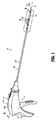
FIG. 1 is a perspective view of an endoscopic surgical system in accordance with the present disclosure; -
FIG. 2 is an enlarged, top perspective view of a distal portion of the endoscopic surgical system ofFIG. 1 ; -
FIG. 3 is a bottom perspective view of the distal portion of the endoscopic surgical system shown inFIG. 2 ; -
FIG. 4 is a perspective view, with parts separated, of an end effector of the endoscopic surgical system ofFIG. 1 ; -
FIG. 5 is an enlarged perspective view of the indicated area of detail shown inFIG. 4 . -
FIG. 6 is a perspective view of a shipping wedge of the endoscopic surgical system ofFIG. 1 ; -
FIG. 7 is a perspective view, with parts separated, of an elongated body portion of the endoscopic surgical system ofFIG. 1 ; -
FIG. 8 is an enlarged, perspective view of the indicated area of detail shown inFIG. 7 ; -
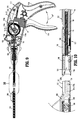
FIG. 9 is a cross-sectional view of the endoscopic surgical system ofFIG. 1 , as taken along line segment 9-9 ofFIG. 1 , the endoscopic surgical system shown in a first state; -
FIG. 10 is an enlarged, elevational view of the indicated area of detail shown inFIG. 9 ; -
FIG. 11 is a cross-sectional view of a portion of the endoscopic surgical system ofFIG. 1 in a second state; -
FIG. 12 is an enlarged view of the indicated area of detail shown inFIG. 11 ; -
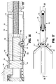
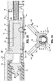
FIGS. 13-18 are progressive views illustrating an assembly of the endoscopic surgical system ofFIG. 1 ; and -
FIGS. 19-22 are progressive views illustrating a removal of the shipping wedge from the endoscopic surgical system ofFIG. 1 . - Embodiments of the presently disclosed devices are described in detail with reference to the drawings, in which like reference numerals designate identical or corresponding elements in each of the several views. As used herein, the term "distal" refers to that portion of the device that is farther from the user, while the term "proximal" refers to that portion of the device that is closer to the user.
- Non-limiting examples of endoscopic surgical devices according to the present disclosure include manual, mechanical and/or electromechanical surgical tack appliers (i.e., tackers) and the like. For a more detailed description of similar endoscopic surgical devices and components thereof that can be used with, or adapted for use with, the presently described endoscopic surgical devices, reference can be made to
U.S. patent application serial number 13/974,338, filed on August 23, 2013 - Referring initially to
FIGS. 1-8 , an endoscopic surgical system is shown generally as 10. Endoscopicsurgical system 10 includes an endoscopic surgical device in the form of an endoscopic surgical tack applier ortacker 100, and ashipping wedge 200.Tack applier 100 includes ahandle assembly 110 and anelongated body portion 120 extending distally along a longitudinal axis "L" fromhandle assembly 110 to anend effector 130 at a distal end thereof that is selectively detachable/attachable from/toelongated body portion 120. -
Handle assembly 110 includes ahandle housing 112 having a first half-section 112a and asecond half section 112b joined to one another to form astationary handle 112c. First half-section 112a andsecond half section 112b ofhandle housing 112 may be joined to one another using known methods by those of skill in the art, including and not limited to welding, fasteners (i.e., screws) and the like. - Referring also to
FIG. 9 , handleassembly 110 includes atrigger 114 connected to handlehousing 112 about a pivot point "P" for pivoting movement relative to handlehousing 112 as illustrated by arrow "A1."Handle assembly 110 includes a biasingmember 116 configured for maintainingtrigger 114 in an extended or un-actuated position.Biasing member 116 is also configured to have a spring constant sufficient to returntrigger 114 to the un-actuated position. -
Trigger 114 defines agear rack 114a formed thereon at a location opposite a hand grip portion and remote from the pivot point "P" oftrigger 114.Gear rack 114a oftrigger 114 is configured for operative engagement with apinion gear 114b rotatably supported inhandle housing 112. - Handle assembly 110 further includes a
bevel gear 114c, in the form of a crown gear, operatively engaged/associated withpinion gear 114b and rotatably mounted to handlehousing 112.Bevel gear 114c is operatively engaged/associated with adrive gear 118 rotatably mounted to handlehousing 112. Gear components such asgear rack 114a,pinion gear 114b,bevel gear 114c,drive gear 118, and/or teeth thereof can have any suitable configuration for interacting/enmeshing with one another. For example, these gear components can be configured and dimensioned such that one complete squeeze oftrigger 114 results in one complete revolution ofpinion gear 114b causingdrive gear 118 to rotate the required number of turns to deliver the surgical fasterner. - As seen in
FIGS. 9 and11 ,drive gear 118 defines anon-circular opening 118a dimensioned to receive a proximal end portion of aninner shaft assembly 140 ofelongated body portion 120.Non-circular opening 118a can have a transverse cross-sectional profile with any suitable shape such as a D-shape, for example, to transmit torque to theinner shaft assembly 140. - Referring also to
FIGS. 10 and11 ,elongated body portion 120 includes anouter tube 122 that supportsinner shaft assembly 140.Outer tube 122 includes aproximal portion 124 and adistal portion 126. - With reference to
FIG. 7 ,proximal portion 124 includes anouter surface 124a that defines a throughbore 124b extending transversely therethrough and aninner surface 124c that defineslumen 124d extending longitudinally therealong. A distal end ofinner surface 124c defines a threadedportion 124e therealong. - Referring to
FIG. 8 ,distal portion 126 ofouter tube 122 includes anouter wall 126a. An inner surface ofouter wall 126a defines acentral bore 126b. Apivot portion 126c extends proximally fromouter wall 126a and includes a pair of opposedprotuberances 126d, each of which extends from one of the side surfaces ofpivot portion 126c (only one of the pair of opposedprotuberances 126d shown inFIG. 8 ).Outer wall 126a extends distally to first and second rotational lock features 126e (e.g., on bottom of outer tube 122 - shown facing upwards inFIG. 8 ), 126f (e.g., on top of outer tube 122 - shown facing downwards inFIG. 8 ). Each of first and second rotational lock features 126e, 126f includes a pair of tapered side surfaces 126g. One or both of first and second rotational lock features 126e, 126f can have any suitable shape such as trapezoidal, for example, to facilitate rotational locking interaction with a counterpart shape as described in greater detail below.Outer wall 126a further defines a pair of opposedproximal apertures 126h and an elongated, transversedistal slot 126i, each of which extends throughouter wall 126a. As seen inFIGS. 14 and 15 ,distal portion 126 includes analignment feature 126j positioned thereon to facilitate alignment ofdistal portion 126 relative to endeffector 130, as described in greater detail below. - Referring again to
FIG. 11 ,inner shaft assembly 140 includes acoupling member 142 at a proximal end thereof that is slidably supported withinnon-circular opening 118a ofdrive gear 118 and rotatable therewith as illustrated by arrows "A2" and "A3." Couplingmember 142 includes astem 142a having a non-circular, transverse, cross-sectional outer profile at a proximal end thereof that is configured and dimensioned to correspond tonon-circular opening 118a ofdrive gear 118, thereby providing slidable movement therein relative to drivegear 118. In some embodiments,non-circular stem 142a has a D-shape transverse cross-sectional outer profile. Couplingmember 142 extends distally to a mountingportion 142b, operatively engaged/associated with aslider 150, and a biasingmember 160. Mountingportion 142b defines abore 142c that receives a proximal end of biasingmember 160 and includes a plurality ofannular flanges 142d that extends therefrom. The proximal end of biasingmember 160 is secured to an inner surface of mountingportion 142b using any known technique such as peening, welding, fastening or the like.Non-circular stem 142a defines apassage 142d in communication withbore 142c of mountingportion 142b.Non-circular stem 142a includes atransverse passage 142e therethrough in communication withpassage 142d. -
Inner shaft assembly 140 includes a proximalrigid portion 144 having aproximal end 144a received withinpassage 142d ofcoupling member 142. Proximalrigid portion 144 defines anaperture 144e (FIG. 7 ) therethrough in communication withtransverse passage 142e ofcoupling member 142.Aperture 144e of proximalrigid portion 144 andtransverse passage 142e ofcoupling member 142 receive a fastener or a pin (not shown) therein to secure proximalrigid portion 144 withinpassage 142d ofcoupling member 142. In some embodiments,proximal end 144a of proximalrigid portion 144 is secured withinpassage 142d ofcoupling member 142 using any known technique such as peening, welding, fastening or the like. Proximalrigid portion 144 extends to adistal end 144b connected to aproximal end 146a of a distalflexible portion 146 ofinner shaft assembly 140. - With reference to
FIGS. 8 and12 , adistal end 146b of distalflexible portion 146 is connected to aproximal end 148a of adistal tube 148.Distal tube 148 extends to adistal end 148b and defines alongitudinal bore 148c that opens throughdistal end 148b thereof.Distal tube 148 also defines anopening 148d therethrough that is transverse to, and in communication with,longitudinal bore 148c.Longitudinal bore 148c has a D-shaped transverse cross-sectional profile.Longitudinal bore 148c may have any suitable non-circular shape and/or dimension for receiving/interacting with one or more components ofend effector 130.Opening 148d ofdistal tube 140 is configured to receive adetent 170 therein.Detent 170 may have any suitable shape and/or dimension such as spherical and/or rounded for example. In some embodiments,detent 170 may be a ball. - As seen in
FIG. 11 , aslider 150 is slidably supported onhandle assembly 110 and includes afinger pad 152 extending from an outer surface ofhandle assembly 110.Slider 150 further includes amating portion 154 having aflange 156 engaged withannular flanges 142d ofcoupling member 142.Slider 150 is biased to a proximal position by axial forces generated by biasingmember 160. The axial forces are transmitted through interaction betweenflange 156 ofslider 150 andannular flanges 142d ofcoupling member 142.Slider 150 is selectively movable to a distal position to axially advanceinner shaft assembly 140 relative to longitudinal axis "L," as described in greater detail below. - Referring again to
FIG. 11 , anarticulation assembly 180 includes anarticulation actuator 180a supported at a proximal end ofelongated body portion 120 and rotatable thereabout as illustrated by arrow "A4."Articulation actuator 180a is axially fixed within arecess 111 defined withinhandle assembly 110 via one ormore flanges 111a. In some embodiments,flange 111a has an annular configuration.Articulation assembly 180 includes adrive assembly 180b.Drive assembly 180b includes atubular sleeve 182, aslidable tube 184, and anarticulation arm 186. -
Tubular sleeve 182 ofdrive assembly 180b includes first and second protubuerances 182a, 182b extending therefrom that are slidably received by ahelical channel 181 defined withinarticulation actuator 180a so that rotation ofarticulation actuator 180a aboutouter tube 122 ofelongated body portion 120 enablestubular sleeve 182 to axially slide relative toarticulation actuator 180 andouter tube 122 as described in greater detail below.Tubular sleeve 182 further includes first andsecond pins throughbore 124b ofouter tube 122, respectively. -
Slidable tube 184 ofdrive assembly 180b is supported withinouter tube 122 and slidable therealong.Slidable tube 184 defines first andsecond apertures second pins tubular sleeve 182 depending respectively therefrom. First andsecond pins second apertures second apertures throughbore 124b and longitudinally movable therealong astubular sleeve 182 axially translates relative to the longitudinal axis "L." - With reference to
FIG. 7 ,slidable tube 184 further defines alongitudinally extending lumen 184c therethrough and anarticulation member recess 184d that is transverse to lumen 184c and in communication therewith. -
Articulation arm 186 ofdrive assembly 180b includes first andsecond protuberances fourth protuberances second protuberances articulation member recess 184d ofslidable tube 184 and each of third andfourth protuberances opposed apertures 126h ofdistal portion 126 ofouter tube 122, respectively (seeFIG. 8 ). - With continued reference to
FIG. 7 , aclevis 190 ofarticulation assembly 180 includes first and second arms 192, 194 that are coupled by abase 196 and that extend distally frombase 196.Clevis 190 defines acentral passage 198 therethrough. First and second arms 192, 194 definerespective apertures surfaces Apertures protuberances 126d ofdistal portion 126 ofouter tube 122 andbase 196 is supported on a distal end ofslidable tube 184 with the distal end ofslidable tube 184 received withincentral passage 198 ofclevis 190. Witharticulation arm 186 supportingclevis 190 betweenslidable tube 184 anddistal portion 126 ofouter tube 122 viaprotuberances 186a-186d, and with the pair of opposedprotuberances 126d ofdistal portion 126 ofouter tube 122 received withinapertures clevis 190,distal portion 126 ofouter tube 122 is pivotally coupled toclevis 190. Threadedsurfaces clevis 190 are threadably engaged with threadedsurface 124e ofproximal portion 124 ofouter tube 122. - Optionally, clevis 190 can be rotated relative to
proximal portion 124 ofouter tube 122 in order to adjust a longitudinal position ofdistal portion 126 ofouter tube 122 relative toproximal portion 124 to account for changes in length of distalflexible portion 146 ofinner shaft assembly 140. - Turning back to
FIG. 4 ,end effector 130 is configured to removably receive ashipping wedge 200 and for selective connection toelongated body portion 120.End effector 130 includes anouter housing 132 coupled to aninner housing 134 by aspring clip 136.End effector 130 supports and stores a plurality ofanchors 138 such that handleassembly 110,elongated body portion 120, andend effector 130 cooperate to selectively release or fire one or more of the plurality ofanchors 138 fromend effector 130, as described in greater detail below. -
Outer housing 132 includes anouter surface 132a and a threadedinner surface 132b that defines alumen 132c longitudinally therethrough. With reference toFIG. 5 ,outer housing 132 includes aproximal segment 132d and adistal segment 132e. Proximal anddistal segments outer housing 132 have different diameters and are separated at a ledge orshoulder 132f.Distal segment 132e ofouter housing 132 defines a pair ofside slots 132g (only one of the pair ofside slots 132g being shown inFIG. 5 ) in an outer surface thereof.Outer housing 132 defines atransverse aperture 132h throughouter surface 132a and includes a pair of rotational lock features 132i (only one of the pair of rotational lock features 132i being shown inFIG. 5 ) that receives first and second rotational lock features 126e, 126f ofdistal portion 126 ofouter tube 122. Each of the pair of rotational lock features 132i includes a pair of engagingsurfaces 132j. One or both of the pair of engagingsurfaces 132j may include one or more angled, tapered, and/or curved surfaces.Transverse aperture 132h extends along portions of both proximal anddistal segments outer housing 132. As seen inFIGS. 14 and 15 ,proximal segment 132d ofouter housing 132 includes analignment feature 132k positioned to align withalignment feature 126j ofdistal portion 126 ofouter tube 122. Although shown as ribs, alignment features 126j, 132k can include structure or indicia of any size, shape, and/or color suitable for orientingend effector 130 relative toelongated body portion 120 to facilitate proper connection therebetween. - With continued reference to
FIG. 4 ,inner housing 134 includes asupport body 134a having adrive shaft 134b extending proximally therefrom and first andsecond tines second tines anchor channel 134e therebetween that is configured and dimensioned to receive the plurality ofanchors 138.Support body 134a defines an annular channel 134f radially therearound that aligns with the pair ofside slots 132g ofouter housing 132 for receivingclip 136 to longitudinally fixinner housing 134 relative toouter housing 132. Driveshaft 134b defines anannular recess 134g that extends around anarcuate surface 134h ofdrive shaft 134b. Driveshaft 134b further includes aflat surface 134j disposed opposite toarcuate surface 134h. - With reference to
FIGS. 4-8 ,shipping wedge 200 includes abody portion 202, and first andsecond wings body portion 202.Body portion 202 has anouter surface 202a and aninner surface 202b.Inner surface 202b defines achannel 202c that extends axially alongbody 202.Channel 202c is configured and dimensioned to receiveouter housing 132 ofend effector 130. Anengagement nub 208 extends frominner surface 202b intochannel 202c ofshipping wedge 200.Engagement nub 208 is receivable withintransverse aperture 132h ofouter housing 132 and within a proximal portion ofanchor channel 134e while shippingwedge 200 is secured to endeffector 130. First andsecond wings body portion 202 in an initial state in which first andsecond wings channel 202c is configured and dimensioned to engageouter housing 132 ofend effector 130 for maintainingshipping wedge 200 secured to endeffector 130. First andsecond wings body portion 202 outwardly and to furtheropen channel 202c for facilitating attachment and/or removal ofshipping wedge 200 to/from end effector 130 (seeFIG. 20 ). - With reference to
FIGS. 9-22 , a loading ofend effector 130 to handleassembly 110, and an operation oftacker 100 is described. As shown inFIGS. 9-12 , the proximal end ofend effector 130 is aligned with the distal end ofelongated body portion 120. As indicated by arrow "A5,"slider 150 is advanced from an initial position shown inFIG. 9 to the distal position shown inFIG. 11 .Flange 156 ofslider 150 axially drivesannular flanges 142d ofcoupling member 142 to axiallyadvance coupling member 142 such thatnon-circular stem 142a thereof slides within and relative tonon-circular opening 118a ofdrive gear 118, as indicated by arrow "A2" (FIG. 11 ). With proximalrigid portion 144 ofinner shaft assembly 140 fixedly secured tocoupling member 142, axial movement ofcoupling member 142 drives proximalrigid portion 144 ofinner shaft assembly 140 axially such that distalflexible portion 146 drivesdistal tube 148 distally, as indicated by arrows "A6," as seen inFIG. 12 . As the distal end ofdistal tube 148 advances distally beyond the distal end ofdistal portion 126 ofouter tube 122,detent 170, while positioned within opening 148d ofdistal tube 148, slides/floats distally along the inner surface ofouter wall 126a ofdistal portion 126. Once elongatedslot 126i ofdistal portion 126 andopening 148d ofdistal tube 148 are longitudinally aligned,detent 170 is free to float within intoopening 148d ofdistal tube 148 and withinslot 126i of distal portion 126 (see arrow "A7") in order to enable receipt ofinner housing 134 withinbore 148c ofdistal tube 148. - As seen in
FIGS. 14-16 , with alignment features 132k, 126j aligned with one another,drive shaft 134b ofinner housing 134 is then advanced intolongitudinal bore 148c ofdistal tube 148 as indicated by arrows "A8" and "A9." Driveshaft 134b is positioned such thatannular recess 134g ofdrive shaft 134b is aligned withdetent 170 and in communication withopening 148d ofdistal tube 148. - With
inner housing 134 inserted intobore 148c ofdistal tube 148, and withannular recess 134g ofdrive shaft 134b in registration withdetent 170,slider 150 is moved in a proximal direction to withdraw or movedistal tube 148 in a proximal direction to urgedetent 170 out ofelongated slot 126i and intoannular recess 134g ofdrive shaft 134b andopening 148d ofdistal tube 148. - With reference to
FIGS. 17 and18 ,drive shaft 134b ofend effector 130 is then further proximally advanced intodistal tube 148 as indicated by arrows "A11" such thatdetent 170 proximally slides/floats along inner surface ofouter wall 126a ofdistal portion 126 untilinner shaft assembly 140 andslider 150 are positioned back into their initial positions (seeFIG. 9 ) andend effector 130 andelongated body portion 120 are fully engaged and locked together viadetent 170. - As seen in
FIGS. 19 and20 , to removeshipping wedge 200, first andsecond wings body portion 202 flexes radially outwardly as indicated by arrows "A12" and "A13," respectively.Shipping wedge 200 may then be separated fromend effector 130 as indicated by arrows "A14." Withshipping wedge 200 removed, as shown inFIGS. 21 and 22 ,tacker 100 can be fired as described in greater detail below. - During use, a clinician may desire to articulate
end effector 130 relative toelongated body portion 120 and longitudinal axis "L" as indicated by arrow "AA," shown inFIG. 1 . To effectuate articulation,articulation actuator 180a ofarticulation assembly 180 is rotated as indicated by arrow "A4." Rotation ofarticulation actuator 180a imparts linear movement totubular sleeve 182 as illustrated by arrow "A17," as shown inFIG. 11 . Axial movement oftubular sleeve 182 enables first andsecond pins slidable tube 184 withinouter tube 122 relative thereto. Asslidable tube 184 is drawn proximally,articulation arm 186 articulatesdistal portion 126 ofouter tube 122 relative toproximal portion 124 of outer tube in the direction illustrated by arrow "AA." Rotation ofarticulation actuator 180a in an opposite direction drivesslidable tube 184 distally and articulatesdistal portion 126 ofouter tube 122 back toward its initial position in axial alignment withproximal portion 124 ofouter tube 122. - To fire one or more of the plurality of
anchors 138,trigger 114 is drawn proximally towardstationary handle 112c as indicated by arrow "A1," as shown inFIG. 9 . Whiletrigger 114 pivots about pivot point "P," radially movement imparted bygear rack 114a, indicated by arrow "A15," rotatespinion gear 114b andbevel gear 114c as indicated by arrow "A16." Withdrive gear 118 andcoupling member 142 coupled together by non-circular profiles ofnoncircular opening 118a ofdrive gear 118 andnon-circular stem 142a ofcoupling member 142, as shown inFIG. 11 , rotation ofbevel gear 114c imparts rotation ondrive gear 118 andcoupling member 142 ofinner shaft assembly 140, as indicated by arrow "A3." Whiledistal tube 148 ofinner shaft assembly 140 rotates,drive shaft 134b ofinner housing 134 rotates such that first andsecond tines anchors 138 distally along threadedinner surface 132b ofouter housing 132. Withouter housing 132 rotationally fixed relative toouter tube 122 via engagement of first and second rotational lock features 126e, 126f with the pair of rotational lock features 132i (FIG. 5 ), a distal-most anchor of the plurality ofanchors 138 is dispensed from distal end ofend effector 130 upon approximation oftrigger 114 andstationary handle 112c.Trigger 114 is then released and unpproximated fromstationary handle 112c to its initial position relative to handle 112c. The firing process can be repeated as desired until each of the plurality ofanchors 138 is dispensed fromend effector 130. - To remove
end effector 130 fromelongated body portion 120, for example, after a plurality or all ofanchors 138 are dispensed fromend effector 130,slider 150 is again advanced distally untildetent 170 is in registration with or positioned withinelongated slot 126i ofouter tube 122. Oncedetent 170 is received inelongated slot 126i,end effector 130 may be separated fromelongated body portion 120 and a new or reloadedend effector 130 may be reattached and reused, as described above. - As can be appreciated, securement of any of the components of the presently disclosed devices can be effectuated using known fastening techniques such welding, crimping, gluing, fastening, etc.
- Persons skilled in the art will understand that the structures and methods specifically described herein and shown in the accompanying figures are non-limiting exemplary embodiments, and that the description, disclosure, and figures should be construed merely as exemplary of particular embodiments. It is to be understood, therefore, that the present disclosure is not limited to the precise embodiments described, and that various other changes and modifications may be effected by one skilled in the art without departing from the scope or spirit of the disclosure. Additionally, the elements and features shown or described in connection with certain embodiments may be combined with the elements and features of certain other embodiments without departing from the scope of the present disclosure, and that such modifications and variations are also included within the scope of the present disclosure. Accordingly, the subject matter of the present disclosure is not limited by what has been particularly shown and described.
- The invention may be described by reference to the following numbered paragraphs:-
- 1. A surgical device comprising:
- an elongated body portion including an outer tube and an inner shaft assembly, the inner shaft assembly having a distal tube defining a non-circular bore in a distal end thereof, the inner shaft assembly being longitudinally movable through the outer tube, the outer tube and the distal tube defining corresponding openings extending transversely therethrough;
- an end effector configured and dimensioned for selective connection to the elongated body portion, the end effector including a drive shaft extending proximally therefrom and defining an annular recess in an outer surface thereof, the drive shaft having a non-circular transverse cross-sectional profile that is complimentary in shape to the non-circular bore of the distal tube; and
- a detent movable within the openings of the elongated body portion, the detent positionable between the annular recess of the drive shaft and the outer tube of the elongated body portion to connect the end effector to the elongated body portion in response to insertion of the drive shaft into the non-circular bore of the distal tube.
- 2. The surgical device of paragraph 1, wherein the annular recess of the drive shaft has an arcuate cross-sectional profile.
- 3. The surgical device of
paragraph 2, wherein the annular recess of the drive shaft partially circumscribes the drive shaft. - 4. The surgical device of paragraph 1, wherein the inner shaft assembly includes a proximal rigid portion connected to a distal flexible portion.
- 5. The surgical device of paragraph 1, wherein the drive shaft of the end effector and the bore of the distal tube have complementary D-shaped cross-sectional profiles.
- 6. The surgical device of paragraph 1, wherein the drive shaft of the end effector rotates in response to rotation of the inner shaft assembly.
- 7. The surgical device of paragraph 1, wherein the end effector includes an outer housing positioned about the drive shaft, the outer housing of the end effector and the outer tube of the elongated body portion including corresponding mating structures configured and dimensioned for engagement to rotationally align and lock together the elongated body portion and the end effector.
- 8. The surgical device of paragraph 1, further including an articulation assembly having an articulation actuator supported at a proximal end of the elongated body portion and a drive assembly, the outer tube of the elongated body portion including a proximal portion and a distal portion, the drive assembly operatively coupled between the articulation actuator and the distal portion of the outer tube, the articulation actuator being actuatable to articulate the distal portion of the outer tube relative to the proximal portion of the outer tube for articulating the end effector relative to a longitudinal axis defined through the elongated body portion.
- 9. The surgical device of
paragraph 8, wherein the drive assembly includes a slidable tube and an articulation arm, the articulation arm pivotally coupled to the slidable tube and the distal portion of the outer tube, the articulation actuator coupled to the slidable tube, wherein rotation of the articulation actuator longitudinal translates the slidable tube through elongated body portion, wherein longitudinal translation of the slidable tube longitudinally translates the articulation arm to enable the end effector to articulate relative to the longitudinal axis. - 10. The surgical device of paragraph 1, wherein the detent is configured and dimensioned to float between the end effector and the elongated body portion to enable selective connection between the end effector and the elongated body portion.
- 11. The surgical device of
paragraph 10, wherein the detent has a spherical shape. - 12. An end effector configured and dimensioned for releasable connection to an elongated body portion of a surgical fastener applying device, the elongated body portion including a detent, the end effector comprising:
- a proximally extending drive shaft configured and dimensioned for insertion into the elongated body portion of the surgical fastener applying device, the drive shaft defining an annular recess configured and dimensioned to receive the detent such that the detent is positionable between the annular recess and the elongated body portion of the surgical fastener applying device to connect the end effector to the surgical fastener applying device.
- 13. The end effector of
paragraph 12, wherein the annular recess of the drive shaft defines an arcuate cross-sectional profile. - 14. The end effector of
paragraph 12, wherein the annular recess of the drive shaft partially circumscribes the drive shaft. - 15. The end effector of
paragraph 12, wherein the drive shaft has a non-circular transverse cross-sectional profile. - 16. The end effector of
paragraph 12, wherein the drive shaft is D-shaped. - 17. The end effector of
paragraph 12, further including an outer tube supporting the proximally extending drive shaft, the drive shaft being rotatable to fire a plurality of fasteners supported within the outer tube from the outer tube. - 18. A surgical fastener applying device configured and dimensioned for releasable connection to an end effector, the surgical fastener applying device comprising:
- an elongated body portion including an outer tube and an inner shaft assembly, the inner shaft assembly having a distal tube defining a non-circular bore in a distal end thereof, the inner shaft assembly being longitudinally movable through the outer tube, the outer tube and the distal tube defining corresponding openings extending transversely therethrough; and
- a detent movable within the openings of the elongated body portion, the detent configured and dimensioned to float between the end effector and the elongated body portion to enable selective connection between the end effector and the elongated body portion.
- 19. The surgical fastener applying device of
paragraph 18, wherein the detent has a spherical shape. - 20. The surgical fastener applying device of
paragraph 18, further including an articulation assembly having an articulation actuator supported at a proximal end of the elongated body portion and a drive assembly, the outer tube of the elongated body portion including a proximal portion and a distal portion, the drive assembly operatively coupled between the articulation actuator and the distal portion of the outer tube, the articulation actuator being actuatable to articulate the distal portion of the outer tube relative to the proximal portion of the outer tube for articulating the end effector relative to a longitudinal axis defined through the elongated body portion.
Claims (14)
- A surgical device comprising:an elongated body portion including an outer tube and an inner shaft assembly, the inner shaft assembly having a distal tube defining a non-circular bore in a distal end thereof, the inner shaft assembly being longitudinally movable through the outer tube, the outer tube and the distal tube defining corresponding openings extending transversely therethrough;an end effector configured and dimensioned for selective connection to the elongated body portion, the end effector including a drive shaft extending proximally therefrom and defining an annular recess in an outer surface thereof, the drive shaft having a non-circular transverse cross-sectional profile that is complimentary in shape to the non-circular bore of the distal tube; anda detent movable within the openings of the elongated body portion, the detent positionable between the annular recess of the drive shaft and the outer tube of the elongated body portion to connect the end effector to the elongated body portion in response to insertion of the drive shaft into the non-circular bore of the distal tube.
- The surgical device of claim 1, wherein the annular recess of the drive shaft has an arcuate cross-sectional profile; preferably wherein the annular recess of the drive shaft partially circumscribes the drive shaft.
- The surgical device of claim 1 or claim 2, wherein the inner shaft assembly includes a proximal rigid portion connected to a distal flexible portion.
- The surgical device of any preceding claim, wherein the drive shaft of the end effector and the bore of the distal tube have complementary D-shaped cross-sectional profiles; and/or wherein the drive shaft of the end effector rotates in response to rotation of the inner shaft assembly.
- The surgical device of any preceding claim, wherein the end effector includes an outer housing positioned about the drive shaft, the outer housing of the end effector and the outer tube of the elongated body portion including corresponding mating structures configured and dimensioned for engagement to rotationally align and lock together the elongated body portion and the end effector.
- The surgical device of any preceding claim, further including an articulation assembly having an articulation actuator supported at a proximal end of the elongated body portion and a drive assembly, the outer tube of the elongated body portion including a proximal portion and a distal portion, the drive assembly operatively coupled between the articulation actuator and the distal portion of the outer tube, the articulation actuator being actuatable to articulate the distal portion of the outer tube relative to the proximal portion of the outer tube for articulating the end effector relative to a longitudinal axis defined through the elongated body portion; preferably wherein the drive assembly includes a slidable tube and an articulation arm, the articulation arm pivotally coupled to the slidable tube and the distal portion of the outer tube, the articulation actuator coupled to the slidable tube, wherein rotation of the articulation actuator longitudinal translates the slidable tube through elongated body portion, wherein longitudinal translation of the slidable tube longitudinally translates the articulation arm to enable the end effector to articulate relative to the longitudinal axis.
- The surgical device of any preceding claim, wherein the detent is configured and dimensioned to float between the end effector and the elongated body portion to enable selective connection between the end effector and the elongated body portion; preferably wherein the detent has a spherical shape.
- An end effector configured and dimensioned for releasable connection to an elongated body portion of a surgical fastener applying device, the elongated body portion including a detent, the end effector comprising:a proximally extending drive shaft configured and dimensioned for insertion into the elongated body portion of the surgical fastener applying device, the drive shaft defining an annular recess configured and dimensioned to receive the detent such that the detent is positionable between the annular recess and the elongated body portion of the surgical fastener applying device to connect the end effector to the surgical fastener applying device.
- The end effector of claim 12, wherein the annular recess of the drive shaft defines an arcuate cross-sectional profile; and/or wherein the annular recess of the drive shaft partially circumscribes the drive shaft.
- The end effector of claim 12, wherein the drive shaft has a non-circular transverse cross-sectional profile; preferably wherein the drive shaft is D-shaped.
- The end effector of any of claims 8 to 10, further including an outer tube supporting the proximally extending drive shaft, the drive shaft being rotatable to fire a plurality of fasteners supported within the outer tube from the outer tube.
- A surgical fastener applying device configured and dimensioned for releasable connection to an end effector, the surgical fastener applying device comprising:an elongated body portion including an outer tube and an inner shaft assembly, the inner shaft assembly having a distal tube defining a non-circular bore in a distal end thereof, the inner shaft assembly being longitudinally movable through the outer tube, the outer tube and the distal tube defining corresponding openings extending transversely therethrough; anda detent movable within the openings of the elongated body portion, the detent configured and dimensioned to float between the end effector and the elongated body portion to enable selective connection between the end effector and the elongated body portion.
- The surgical fastener applying device of claim 12, wherein the detent has a spherical shape.
- The surgical fastener applying device of claim 12 or claim 13, further including an articulation assembly having an articulation actuator supported at a proximal end of the elongated body portion and a drive assembly, the outer tube of the elongated body portion including a proximal portion and a distal portion, the drive assembly operatively coupled between the articulation actuator and the distal portion of the outer tube, the articulation actuator being actuatable to articulate the distal portion of the outer tube relative to the proximal portion of the outer tube for articulating the end effector relative to a longitudinal axis defined through the elongated body portion.
Applications Claiming Priority (2)
| Application Number | Priority Date | Filing Date | Title |
|---|---|---|---|
| US201562134107P | 2015-03-17 | 2015-03-17 | |
| US15/052,952 US11090097B2 (en) | 2015-03-17 | 2016-02-25 | Connecting end effectors to surgical devices |
Publications (2)
| Publication Number | Publication Date |
|---|---|
| EP3069663A1 true EP3069663A1 (en) | 2016-09-21 |
| EP3069663B1 EP3069663B1 (en) | 2018-10-17 |
Family
ID=55542504
Family Applications (1)
| Application Number | Title | Priority Date | Filing Date |
|---|---|---|---|
| EP16160646.2A Active EP3069663B1 (en) | 2015-03-17 | 2016-03-16 | Connecting end effectors to surgical devices |
Country Status (5)
| Country | Link |
|---|---|
| US (2) | US11090097B2 (en) |
| EP (1) | EP3069663B1 (en) |
| JP (1) | JP6735575B2 (en) |
| CN (1) | CN105982703B (en) |
| AU (1) | AU2016201340B2 (en) |
Cited By (8)
| Publication number | Priority date | Publication date | Assignee | Title |
|---|---|---|---|---|
| CN110099631A (en) * | 2016-12-21 | 2019-08-06 | 爱惜康有限责任公司 | The surgical end-effector for capableing of joint motions with asymmetric shaft arrangement |
| WO2020014315A3 (en) * | 2018-07-12 | 2020-02-20 | Davol Inc. | Surgical instrument with fastener preload lock-out |
| EP3943016A1 (en) * | 2020-07-21 | 2022-01-26 | Covidien LP | Cartridge alignment mechanism for use with surgical devices |
| US11864750B2 (en) | 2020-04-29 | 2024-01-09 | Medos International Sarl | Knotless anchor insertion |
| USD1019945S1 (en) | 2021-12-30 | 2024-03-26 | Medos International Sarl | Suture anchor insertion device |
| USD1028232S1 (en) | 2021-04-27 | 2024-05-21 | Medos International Sarl | Suture anchor insertion device |
| US12029416B2 (en) | 2019-04-17 | 2024-07-09 | Davol Inc. | Surgical instrument with fastener preload lock-out |
| US12137894B2 (en) | 2021-12-30 | 2024-11-12 | Medos International Sarl | Knotless anchor inserter tool extraction |
Families Citing this family (36)
| Publication number | Priority date | Publication date | Assignee | Title |
|---|---|---|---|---|
| ES2301119T3 (en) | 2002-06-11 | 2008-06-16 | Tyco Healthcare Group Lp | MALE TIGHTS FOR HERNIAS. |
| CA2527778C (en) | 2003-06-13 | 2011-11-08 | Tyco Healthcare Group Lp | Multiple member interconnect for surgical instrument and absorbable screw fastener |
| US8926637B2 (en) | 2003-06-13 | 2015-01-06 | Covidien Lp | Multiple member interconnect for surgical instrument and absorbable screw fastener |
| US10478179B2 (en) | 2004-04-27 | 2019-11-19 | Covidien Lp | Absorbable fastener for hernia mesh fixation |
| US9421037B2 (en) * | 2012-05-01 | 2016-08-23 | Globus Medical, Inc. | Dispensing fasteners |
| US9351733B2 (en) | 2013-01-18 | 2016-05-31 | Covidien Lp | Surgical fastener applier |
| US9358010B2 (en) | 2013-03-12 | 2016-06-07 | Covidien Lp | Flex cable and spring-loaded tube for tacking device |
| US9867620B2 (en) | 2013-03-14 | 2018-01-16 | Covidien Lp | Articulation joint for apparatus for endoscopic procedures |
| US9797486B2 (en) * | 2013-06-20 | 2017-10-24 | Covidien Lp | Adapter direct drive with manual retraction, lockout and connection mechanisms |
| US9351728B2 (en) | 2013-06-28 | 2016-05-31 | Covidien Lp | Articulating apparatus for endoscopic procedures |
| US9668730B2 (en) | 2013-06-28 | 2017-06-06 | Covidien Lp | Articulating apparatus for endoscopic procedures with timing system |
| US10085746B2 (en) | 2013-06-28 | 2018-10-02 | Covidien Lp | Surgical instrument including rotating end effector and rotation-limiting structure |
| US9358004B2 (en) | 2013-06-28 | 2016-06-07 | Covidien Lp | Articulating apparatus for endoscopic procedures |
| US20150032130A1 (en) | 2013-07-24 | 2015-01-29 | Covidien Lp | Expanding absorbable tack |
| US9955966B2 (en) * | 2013-09-17 | 2018-05-01 | Covidien Lp | Adapter direct drive with manual retraction, lockout, and connection mechanisms for improper use prevention |
| US10335146B2 (en) | 2014-04-02 | 2019-07-02 | Coviden Lp | Surgical fastener applying apparatus, kits and methods for endoscopic procedures |
| US11090097B2 (en) | 2015-03-17 | 2021-08-17 | Covidien Lp | Connecting end effectors to surgical devices |
| US11432902B2 (en) | 2015-04-10 | 2022-09-06 | Covidien Lp | Surgical devices with moisture control |
| US10617409B2 (en) | 2016-10-21 | 2020-04-14 | Covidien Lp | Surgical end effectors |
| US10743859B2 (en) | 2016-10-21 | 2020-08-18 | Covidien Lp | Surgical end effectors |
| US11298123B2 (en) | 2016-10-21 | 2022-04-12 | Covidien Lp | Surgical end effectors |
| US10888309B2 (en) | 2017-01-31 | 2021-01-12 | Covidien Lp | Surgical fastener devices with geometric tubes |
| US10932804B2 (en) | 2017-10-30 | 2021-03-02 | Ethicon Llc | Surgical instrument with sensor and/or control systems |
| US10736616B2 (en) | 2017-10-30 | 2020-08-11 | Ethicon Llc | Surgical instrument with remote release |
| US11129634B2 (en) | 2017-10-30 | 2021-09-28 | Cilag Gmbh International | Surgical instrument with rotary drive selectively actuating multiple end effector functions |
| US11298126B2 (en) | 2018-05-02 | 2022-04-12 | Covidien Lp | Shipping wedge for end effector installation onto surgical devices |
| US11116500B2 (en) | 2018-06-28 | 2021-09-14 | Covidien Lp | Surgical fastener applying device, kits and methods for endoscopic procedures |
| CN111820978A (en) * | 2019-04-16 | 2020-10-27 | 柯惠Lp公司 | Surgical device with humidity control |
| US11523817B2 (en) | 2019-06-27 | 2022-12-13 | Covidien Lp | Endoluminal pursestring device |
| US11540827B2 (en) * | 2019-12-13 | 2023-01-03 | Covidien Lp | Hand-held electromechanical surgical instruments |
| USD944985S1 (en) | 2019-12-19 | 2022-03-01 | Covidien Lp | Positioning guide cuff |
| USD944984S1 (en) | 2019-12-19 | 2022-03-01 | Covidien Lp | Tubular positioning guide |
| US11197675B2 (en) | 2019-12-19 | 2021-12-14 | Covidien Lp | Positioning guide for surgical instruments and surgical instrument systems |
| US11779343B2 (en) * | 2020-02-26 | 2023-10-10 | Covidien Lp | Staple reload assembly with releasable knife |
| US11517357B2 (en) * | 2021-02-03 | 2022-12-06 | Warsaw Orthopedic, Inc. | Combination set screw breakoff and tab breaker instrument |
| USD1109327S1 (en) | 2024-09-06 | 2026-01-13 | Covidien Lp | Handle for a surgical instrument |
Citations (9)
| Publication number | Priority date | Publication date | Assignee | Title |
|---|---|---|---|---|
| FR2361089A1 (en) * | 1976-08-09 | 1978-03-10 | American Safety Equip | SURGICAL INSTRUMENT USING A PNEUMATIC PULSE MOTOR |
| US5505737A (en) * | 1994-07-01 | 1996-04-09 | Midas Rex Pneumatic Tools, Inc. | Quick release coupling for a dissecting tool |
| EP0716831A1 (en) * | 1994-12-13 | 1996-06-19 | Bristol-Myers Squibb Company | Surgical cutting device with safety interlock |
| WO1997000149A1 (en) * | 1995-06-14 | 1997-01-03 | Sodem Diffusion S.A. | Quick connection method and device, and surgical instrument for driving interchangeable rotary tools |
| US20030060841A1 (en) * | 2001-09-25 | 2003-03-27 | Del Rio Eddy H. | High speed surgical instrument |
| US20060041268A1 (en) * | 2004-08-17 | 2006-02-23 | Medtronic, Inc. | Surgical attachment instrument and method |
| EP2005896A2 (en) * | 2007-06-18 | 2008-12-24 | Ethicon Endo-Surgery, Inc. | Surgical stapling and cutting instrument with improved closure system |
| EP2090233A2 (en) * | 2008-02-15 | 2009-08-19 | Ethicon Endo-Surgery, Inc. | Closure systems for a surgical cutting and stapling instrument |
| CA2857855A1 (en) * | 2013-08-23 | 2015-02-23 | Covidien Lp | Articulating apparatus for endoscopic procedures |
Family Cites Families (237)
| Publication number | Priority date | Publication date | Assignee | Title |
|---|---|---|---|---|
| US3032359A (en) * | 1958-05-05 | 1962-05-01 | Crawford Fitting Co | Quick connect coupling |
| US3866510A (en) | 1967-06-05 | 1975-02-18 | Carl B H Eibes | Self-tapping threaded bushings |
| US4403959A (en) * | 1981-07-31 | 1983-09-13 | Kabushiki Kaisha Yoshida Seisakusho | Coupling device for a dental instrument |
| US4577875A (en) * | 1982-10-29 | 1986-03-25 | Miyakawa Industry Co., Ltd. | Exchange chuck for a tool |
| US4924865A (en) | 1986-05-20 | 1990-05-15 | Concept, Inc. | Repair tack for bodily tissue |
| US4730726A (en) | 1987-04-21 | 1988-03-15 | United States Surgical Corporation | Sealed sterile package |
| US4846714A (en) * | 1988-05-16 | 1989-07-11 | Kaman Instrumentation Corporation | Quick disconnect connector |
| CH681273A5 (en) | 1988-12-16 | 1993-02-26 | Sulzer Ag | |
| US5382254A (en) | 1989-07-18 | 1995-01-17 | United States Surgical Corporation | Actuating handle for surgical instruments |
| US5129906A (en) | 1989-09-08 | 1992-07-14 | Linvatec Corporation | Bioabsorbable tack for joining bodily tissue and in vivo method and apparatus for deploying same |
| US5236563A (en) | 1990-06-18 | 1993-08-17 | Advanced Surface Technology Inc. | Surface-modified bioabsorbables |
| US5085661A (en) | 1990-10-29 | 1992-02-04 | Gerald Moss | Surgical fastener implantation device |
| DE4108952A1 (en) | 1991-03-19 | 1992-09-24 | Beiersdorf Ag | DEVICE FOR SETTING WIND CLASPS |
| US5144942A (en) | 1991-03-21 | 1992-09-08 | United States Surgical Corporation | Endoscopic instrumentation kit and package therefor |
| US5171247A (en) | 1991-04-04 | 1992-12-15 | Ethicon, Inc. | Endoscopic multiple ligating clip applier with rotating shaft |
| US5171249A (en) | 1991-04-04 | 1992-12-15 | Ethicon, Inc. | Endoscopic multiple ligating clip applier |
| US5156267A (en) | 1991-06-14 | 1992-10-20 | Dynamic Bio-Apparatuses, Inc. | Syringe inhibiting container |
| US5207697A (en) * | 1991-06-27 | 1993-05-04 | Stryker Corporation | Battery powered surgical handpiece |
| US5228256A (en) | 1991-10-02 | 1993-07-20 | Ross Dreveny | Anchor means and apparatus for installing same |
| US5312023A (en) | 1991-10-18 | 1994-05-17 | United States Surgical Corporation | Self contained gas powered surgical apparatus |
| US5356064A (en) * | 1991-10-18 | 1994-10-18 | United States Surgical Corporation | Apparatus and method for applying surgical staples to attach an object to body tissue |
| US5397046A (en) | 1991-10-18 | 1995-03-14 | United States Surgical Corporation | Lockout mechanism for surgical apparatus |
| US5478003A (en) * | 1991-10-18 | 1995-12-26 | United States Surgical Corporation | Surgical apparatus |
| US5433721A (en) | 1992-01-17 | 1995-07-18 | Ethicon, Inc. | Endoscopic instrument having a torsionally stiff drive shaft for applying fasteners to tissue |
| CA2088883A1 (en) | 1992-02-13 | 1993-08-14 | David T. Green | Endoscopic ligating instrument |
| US5246450A (en) | 1992-03-10 | 1993-09-21 | Edward Weck Incorporated | High capacity medical clip feeding and dispensing mechanism |
| US5342373A (en) | 1992-09-14 | 1994-08-30 | Ethicon, Inc. | Sterile clips and instrument for their placement |
| US5381943A (en) | 1992-10-09 | 1995-01-17 | Ethicon, Inc. | Endoscopic surgical stapling instrument with pivotable and rotatable staple cartridge |
| US5601224A (en) | 1992-10-09 | 1997-02-11 | Ethicon, Inc. | Surgical instrument |
| US5662662A (en) | 1992-10-09 | 1997-09-02 | Ethicon Endo-Surgery, Inc. | Surgical instrument and method |
| US5330487A (en) | 1992-12-17 | 1994-07-19 | Tfi Acquistion Corp. | Drive mechanism for surgical instruments |
| US5403327A (en) * | 1992-12-31 | 1995-04-04 | Pilling Weck Incorporated | Surgical clip applier |
| US5398861A (en) | 1993-04-16 | 1995-03-21 | United States Surgical Corporation | Device for driving surgical fasteners |
| US5353929A (en) | 1993-04-19 | 1994-10-11 | United States Surgical Corporation | Package for surgical instrument |
| ATE153231T1 (en) | 1993-04-27 | 1997-06-15 | American Cyanamid Co | AUTOMATIC LAPAROSCOPIC APPLICATOR FOR LIVING CLIPS |
| US5467911A (en) | 1993-04-27 | 1995-11-21 | Olympus Optical Co., Ltd. | Surgical device for stapling and fastening body tissues |
| US5439468A (en) | 1993-05-07 | 1995-08-08 | Ethicon Endo-Surgery | Surgical clip applier |
| US5522844A (en) | 1993-06-22 | 1996-06-04 | Johnson; Lanny L. | Suture anchor, suture anchor installation device and method for attaching a suture to a bone |
| DE69415676T2 (en) | 1993-08-03 | 1999-05-20 | Howmedica Inc., New York, N.Y. | LOCKING ROD COMPRESSION DEVICE |
| US5344061A (en) | 1993-08-03 | 1994-09-06 | Lawrence Crainich | Ratchet assembly for medical instrument |
| US5407070A (en) | 1993-08-18 | 1995-04-18 | Bascos; Christine M. | One-time resealable package for needled medical devices |
| US5381896A (en) | 1993-10-06 | 1995-01-17 | Ethicon, Inc. | Presentation tray for surgical instruments |
| AU1011595A (en) | 1994-01-13 | 1995-07-20 | Ethicon Inc. | Spiral surgical tack |
| US5466243A (en) | 1994-02-17 | 1995-11-14 | Arthrex, Inc. | Method and apparatus for installing a suture anchor through a hollow cannulated grasper |
| CA2143560C (en) | 1994-03-02 | 2007-01-16 | Mark Fogelberg | Sterile occlusion fasteners and instrument and method for their placement |
| US5681330A (en) | 1994-03-02 | 1997-10-28 | Ethicon Endo-Surgery, Inc. | Sterile occlusion fasteners and instrument and method for their placement |
| US5474566A (en) | 1994-05-05 | 1995-12-12 | United States Surgical Corporation | Self-contained powered surgical apparatus |
| US5601571A (en) | 1994-05-17 | 1997-02-11 | Moss; Gerald | Surgical fastener implantation device |
| US5496323A (en) * | 1994-06-02 | 1996-03-05 | Intermedics Orthopedics, Inc. | Orthopedic instrument with quarter-turn disconnect mechanism |
| EP0699418A1 (en) | 1994-08-05 | 1996-03-06 | United States Surgical Corporation | Self-contained powered surgical apparatus |
| US5582616A (en) | 1994-08-05 | 1996-12-10 | Origin Medsystems, Inc. | Surgical helical fastener with applicator |
| US5562685A (en) | 1994-09-16 | 1996-10-08 | General Surgical Innovations, Inc. | Surgical instrument for placing suture or fasteners |
| US5730744A (en) | 1994-09-27 | 1998-03-24 | Justin; Daniel F. | Soft tissue screw, delivery device, and method |
| US5685474A (en) | 1994-10-04 | 1997-11-11 | United States Surgical Corporation | Tactile indicator for surgical instrument |
| DE19509966A1 (en) | 1995-03-18 | 1996-09-19 | Frank Ullrich Schuetz | Stapler and nail for surgery |
| DE19514098C2 (en) * | 1995-04-13 | 2001-01-25 | Storz Karl Gmbh & Co Kg | Coupling for tubular shaft instruments |
| US5553765A (en) | 1995-04-28 | 1996-09-10 | Ethicon Endo-Surgery, Inc. | Surgical stapler with improved operating lever mounting arrangement |
| US5626613A (en) | 1995-05-04 | 1997-05-06 | Arthrex, Inc. | Corkscrew suture anchor and driver |
| US5509695A (en) * | 1995-06-01 | 1996-04-23 | Pilot Industries, Inc. | Precocked quick connect fluid coupling having a v-shaped holding ring |
| US5762256A (en) * | 1995-08-28 | 1998-06-09 | United States Surgical Corporation | Surgical stapler |
| US5697935A (en) | 1995-09-12 | 1997-12-16 | Medex Marketing, Inc. | Device and method for removing fastening implements from bone |
| US5997552A (en) * | 1995-10-20 | 1999-12-07 | United States Surgical Corporation | Meniscal fastener applying device |
| US5582615A (en) * | 1995-10-30 | 1996-12-10 | Pilling Weck, Incorporated | Handle for surgical clip applicator systems |
| JP3047159B2 (en) * | 1995-11-09 | 2000-05-29 | 矢崎総業株式会社 | Connector mating structure |
| JPH09149906A (en) | 1995-11-29 | 1997-06-10 | Nagoya Rashi Seisakusho:Kk | Tool for curing bone disease |
| US5649931A (en) | 1996-01-16 | 1997-07-22 | Zimmer, Inc. | Orthopaedic apparatus for driving and/or removing a bone screw |
| US5762255A (en) | 1996-02-20 | 1998-06-09 | Richard-Allan Medical Industries, Inc. | Surgical instrument with improvement safety lockout mechanisms |
| US6099537A (en) | 1996-02-26 | 2000-08-08 | Olympus Optical Co., Ltd. | Medical treatment instrument |
| US5782844A (en) | 1996-03-05 | 1998-07-21 | Inbae Yoon | Suture spring device applicator |
| US5732806A (en) | 1996-03-29 | 1998-03-31 | Pilling Weck, Incorporated | Compensator to prevent backlash in a surgical instrument |
| US5747953A (en) | 1996-03-29 | 1998-05-05 | Stryker Corporation | Cordless, battery operated surical tool |
| EP0800796A1 (en) | 1996-04-12 | 1997-10-15 | Caron, Philippe | Screwdriving device incorporating a screw loader, particularly for use in maxillo-facial surgery |
| US5830221A (en) | 1996-09-20 | 1998-11-03 | United States Surgical Corporation | Coil fastener applier |
| WO1998011814A2 (en) | 1996-09-20 | 1998-03-26 | United States Surgical Corporation | Coil fastener applier and remover |
| US6109500A (en) * | 1996-10-04 | 2000-08-29 | United States Surgical Corporation | Lockout mechanism for a surgical stapler |
| CA2217435C (en) | 1996-10-04 | 2006-08-29 | United States Surgical Corporation | Tissue fastener implantation apparatus and method |
| US5928252A (en) | 1997-01-21 | 1999-07-27 | Regen Biologics, Inc. | Device and method for driving a needle and meniscal repair |
| US5843087A (en) | 1997-01-30 | 1998-12-01 | Ethicon, Inc. | Suture anchor installation tool |
| DE19707373C1 (en) * | 1997-02-25 | 1998-02-05 | Storz Karl Gmbh & Co | Releasable connection of two tube shaft instruments or instrument parts |
| JP3301530B2 (en) * | 1997-02-26 | 2002-07-15 | 住友電装株式会社 | connector |
| US5897564A (en) | 1997-04-08 | 1999-04-27 | Ethicon Endo-Surgery, Inc. | Endoscopic instrument assembly for fastening tissue |
| US5910105A (en) | 1997-04-14 | 1999-06-08 | C.R. Bard, Inc. | Control handle for an endoscope |
| US5941439A (en) | 1997-05-14 | 1999-08-24 | Mitek Surgical Products, Inc. | Applicator and method for deploying a surgical fastener in tissue |
| US5957924A (en) | 1997-05-22 | 1999-09-28 | Bionx Implants Oy | Installation tool for suture anchor |
| US5865361A (en) * | 1997-09-23 | 1999-02-02 | United States Surgical Corporation | Surgical stapling apparatus |
| US6010513A (en) | 1997-11-26 | 2000-01-04 | Bionx Implants Oy | Device for installing a tissue fastener |
| US6457625B1 (en) | 1998-02-17 | 2002-10-01 | Bionx Implants, Oy | Device for installing a tissue fastener |
| US5961524A (en) | 1998-03-11 | 1999-10-05 | Stryker Technologies Corporation | Screw and method of attachment to a substrate |
| US8075570B2 (en) | 2001-11-28 | 2011-12-13 | Aptus Endosystems, Inc. | Intraluminal prosthesis attachment systems and methods |
| US7491232B2 (en) | 1998-09-18 | 2009-02-17 | Aptus Endosystems, Inc. | Catheter-based fastener implantation apparatus and methods with implantation force resolution |
| US5931844A (en) | 1998-03-31 | 1999-08-03 | Smith & Nephew, Inc. | Surgical drive tool |
| US5976160A (en) | 1998-03-31 | 1999-11-02 | Design Standards Corporation | Handle mechanism with two distinct pivot points |
| JP3561143B2 (en) * | 1998-04-02 | 2004-09-02 | 矢崎総業株式会社 | Lock structure |
| AU733868B2 (en) | 1998-05-12 | 2001-05-31 | Boston Scientific Limited | Manual bone anchor placement devices |
| US6261302B1 (en) | 1998-06-26 | 2001-07-17 | Ethicon Endo-Surgery, Inc. | Applier for implantable surgical marker |
| US6228098B1 (en) | 1998-07-10 | 2001-05-08 | General Surgical Innovations, Inc. | Apparatus and method for surgical fastening |
| US6039753A (en) | 1998-07-16 | 2000-03-21 | Meislin; Robert | Single unit surgical fastener and method |
| US5911722A (en) | 1998-07-23 | 1999-06-15 | Millenium Devices Llc | Leban/Gordon surgical hand driver |
| US6146387A (en) | 1998-08-26 | 2000-11-14 | Linvatec Corporation | Cannulated tissue anchor system |
| EP1121057A1 (en) | 1998-09-18 | 2001-08-08 | United States Surgical Corporation | Endovascular fastener applicator |
| US6235058B1 (en) | 1998-10-19 | 2001-05-22 | Douglas B. Huene | Bone plug anchoring device and methods for anchoring one or more tendons or other grafts using the bone plug anchoring device |
| US6126670A (en) | 1998-12-16 | 2000-10-03 | Medtronic, Inc. | Cordless surgical handpiece with disposable battery; and method |
| US6887244B1 (en) | 1998-12-16 | 2005-05-03 | Medtronic, Inc. | Cordless surgical handpiece with disposable battery; and method |
| AU5924099A (en) | 1998-12-31 | 2000-07-24 | Jeffrey E. Yeung | Tissue fastening devices and delivery means |
| US6074395A (en) | 1999-02-02 | 2000-06-13 | Linvatec Corporation | Cannulated tissue anchor insertion system |
| US6387113B1 (en) | 1999-02-02 | 2002-05-14 | Biomet, Inc. | Method and apparatus for repairing a torn meniscus |
| US6402757B1 (en) | 1999-03-12 | 2002-06-11 | Biomet, Inc. | Cannulated fastener system for repair of bone fracture |
| FR2795301B1 (en) | 1999-06-25 | 2001-08-31 | Prec | ENDOSCOPIC SURGERY INSTRUMENT |
| DE19930426C2 (en) * | 1999-07-01 | 2001-05-03 | Storz Karl Gmbh & Co Kg | Medical, in particular surgical instrument |
| DE19935042B4 (en) * | 1999-07-26 | 2004-02-05 | Aesculap Ag & Co. Kg | Surgical tubular shaft instrument |
| US6132435A (en) | 1999-09-14 | 2000-10-17 | Synthes (Usa) | Torque limiting device for surgical use |
| DE59901090D1 (en) | 1999-12-23 | 2002-05-02 | Storz Karl Gmbh & Co Kg | Decentralized drive screw |
| US6942674B2 (en) | 2000-01-05 | 2005-09-13 | Integrated Vascular Systems, Inc. | Apparatus and methods for delivering a closure device |
| JP4295459B2 (en) * | 2000-02-18 | 2009-07-15 | ストライカー コーポレイション | Surgical instrument cutting accessories |
| US6440136B1 (en) | 2000-05-24 | 2002-08-27 | Medtronic Ps Medical, Inc. | Apparatus for attaching to bone |
| US7296804B2 (en) | 2000-06-24 | 2007-11-20 | Precimed S.A. | Hand-held instrument holder for surgical use |
| US7204847B1 (en) | 2000-07-28 | 2007-04-17 | C. R. Bard, Inc. | Implant anchor systems |
| US6632228B2 (en) | 2000-08-23 | 2003-10-14 | Scimed Life System, Inc. | System, method, and apparatus for accurately deploying particular medical appliances at a target site |
| WO2002017771A2 (en) | 2000-09-01 | 2002-03-07 | Advanced Vascular Technologies, Llc | Multi-fastener surgical apparatus and method |
| WO2002024079A1 (en) | 2000-09-22 | 2002-03-28 | Codman & Shurtleff, Inc. | Instrument and method for applying surgical fastners |
| US6425900B1 (en) | 2000-10-19 | 2002-07-30 | Ethicon Endo-Surgery | Method for attaching hernia mesh |
| US6773438B1 (en) | 2000-10-19 | 2004-08-10 | Ethicon Endo-Surgery | Surgical instrument having a rotary lockout mechanism |
| US6572626B1 (en) | 2000-10-19 | 2003-06-03 | Ethicon Endo-Surgery, Inc. | Surgical instrument having a fastener delivery mechanism |
| US6551333B2 (en) | 2000-10-19 | 2003-04-22 | Ethicon Endo-Surgery, Inc. | Method for attaching hernia mesh |
| AU2002232798B2 (en) | 2000-10-23 | 2006-01-05 | Covidien Lp | Absorbable fastener and applying apparatus |
| US6733506B1 (en) | 2000-11-16 | 2004-05-11 | Ethicon, Inc. | Apparatus and method for attaching soft tissue to bone |
| US6439446B1 (en) | 2000-12-01 | 2002-08-27 | Stephen J. Perry | Safety lockout for actuator shaft |
| US6716226B2 (en) | 2001-06-25 | 2004-04-06 | Inscope Development, Llc | Surgical clip |
| US6663656B2 (en) | 2001-02-26 | 2003-12-16 | Arthrex, Inc. | Torque driver for interference screw |
| CA2391635C (en) | 2001-07-02 | 2007-12-18 | Depuy France | Device for joining bony parts |
| WO2003034925A2 (en) | 2001-10-23 | 2003-05-01 | Tyco Healthcare Group Lp | Surgical fasteners |
| AU2002353807B2 (en) | 2001-11-28 | 2008-08-14 | Aptus Endosystems, Inc. | Endovascular aneurysm repair system |
| US6929661B2 (en) | 2001-11-28 | 2005-08-16 | Aptus Endosystems, Inc. | Multi-lumen prosthesis systems and methods |
| US7128754B2 (en) | 2001-11-28 | 2006-10-31 | Aptus Endosystems, Inc. | Catheter-based fastener implantation apparatus and methods |
| US8231639B2 (en) | 2001-11-28 | 2012-07-31 | Aptus Endosystems, Inc. | Systems and methods for attaching a prosthesis within a body lumen or hollow organ |
| US7122028B2 (en) | 2001-12-19 | 2006-10-17 | Allegiance Corporation | Reconfiguration surgical apparatus |
| US6869435B2 (en) | 2002-01-17 | 2005-03-22 | Blake, Iii John W | Repeating multi-clip applier |
| US6749621B2 (en) | 2002-02-21 | 2004-06-15 | Integrated Vascular Systems, Inc. | Sheath apparatus and methods for delivering a closure device |
| ES2301119T3 (en) | 2002-06-11 | 2008-06-16 | Tyco Healthcare Group Lp | MALE TIGHTS FOR HERNIAS. |
| CN2547267Y (en) | 2002-06-13 | 2003-04-30 | 张金六 | Bathing towel |
| US6966919B2 (en) | 2002-09-20 | 2005-11-22 | Id, Llc | Instrument for applying a surgical fastener particularly for the transoral treatment of gastroesophageal reflux disease (GERD) |
| US7811312B2 (en) | 2002-12-04 | 2010-10-12 | Morphographics, Lc | Bone alignment implant and method of use |
| US6755836B1 (en) | 2002-12-20 | 2004-06-29 | High Plains Technology Group, Llc | Bone screw fastener and apparatus for inserting and removing same |
| DE10300787B4 (en) | 2003-01-13 | 2016-06-09 | A.M.I (Agency for Medical Innovations GmbH) | Device for attaching a mesh to human or animal tissue |
| US7070601B2 (en) | 2003-01-16 | 2006-07-04 | Triage Medical, Inc. | Locking plate for bone anchors |
| DE10311455B3 (en) * | 2003-03-15 | 2004-09-16 | Aesculap Ag & Co. Kg | Coupling for a surgical rotary drive hand piece comprises a catch which slides against the action of a spring into a extended position using a tool |
| US7461574B2 (en) | 2003-04-28 | 2008-12-09 | Biomet Microfixation, Llc | Multiple screw delivery apparatus |
| US8926637B2 (en) | 2003-06-13 | 2015-01-06 | Covidien Lp | Multiple member interconnect for surgical instrument and absorbable screw fastener |
| CA2527778C (en) | 2003-06-13 | 2011-11-08 | Tyco Healthcare Group Lp | Multiple member interconnect for surgical instrument and absorbable screw fastener |
| CA2724284C (en) * | 2003-06-17 | 2013-02-26 | Tyco Healthcare Group Lp | Surgical stapling device |
| US20070088390A1 (en) | 2003-07-11 | 2007-04-19 | Endogun Medical Systems Ltd. | Surgical fasteners and devices for surgical fastening |
| KR100546348B1 (en) * | 2003-07-23 | 2006-01-26 | 삼성전자주식회사 | Flash memory system and its data storage method |
| US7000819B2 (en) | 2003-09-29 | 2006-02-21 | Ethicon Endo-Surgery, Inc. | Surgical stapling instrument having multistroke firing incorporating a traction-biased ratcheting mechanism |
| US6905057B2 (en) | 2003-09-29 | 2005-06-14 | Ethicon Endo-Surgery, Inc. | Surgical stapling instrument incorporating a firing mechanism having a linked rack transmission |
| DE10356566B3 (en) * | 2003-12-04 | 2005-07-21 | Airbus Deutschland Gmbh | Lockable plug connection |
| US6988650B2 (en) | 2003-12-30 | 2006-01-24 | Ethicon Endo-Surgery, Inc. | Retaining pin lever advancement mechanism for a curved cutter stapler |
| US10478179B2 (en) | 2004-04-27 | 2019-11-19 | Covidien Lp | Absorbable fastener for hernia mesh fixation |
| US8114099B2 (en) | 2004-04-27 | 2012-02-14 | Tyco Healthcare Group Lp | Absorbable anchor for hernia mesh fixation |
| US20060129152A1 (en) | 2004-12-10 | 2006-06-15 | Shipp John I | Absorbable Anchor for Hernia Mesh Fixation |
| US7758612B2 (en) | 2004-04-27 | 2010-07-20 | Tyco Healthcare Group Lp | Surgery delivery device and mesh anchor |
| US20090118776A1 (en) | 2004-09-24 | 2009-05-07 | Biomec, Inc. | Tissue anchors |
| JP5047799B2 (en) | 2004-10-08 | 2012-10-10 | タイコ ヘルスケア グループ リミテッド パートナーシップ | Endoscopic surgical clip applier |
| US7604659B2 (en) | 2004-11-09 | 2009-10-20 | Lee James M | Method and apparatus for repair of torn rotator cuff tendons |
| US9700334B2 (en) | 2004-11-23 | 2017-07-11 | Intuitive Surgical Operations, Inc. | Articulating mechanisms and link systems with torque transmission in remote manipulation of instruments and tools |
| CN101193600B (en) * | 2005-04-29 | 2010-09-08 | 博维医药公司 | Forceps for performing endoscopic or arthroscopic procedures |
| US7229306B2 (en) * | 2005-05-19 | 2007-06-12 | Sumitomo Wiring Systems, Ltd. | Connector and a connector assembly |
| US8333776B2 (en) | 2005-05-20 | 2012-12-18 | Neotract, Inc. | Anchor delivery system |
| US20070031184A1 (en) * | 2005-08-02 | 2007-02-08 | Baxstrom Luke J | Connector |
| JP4770346B2 (en) * | 2005-09-13 | 2011-09-14 | 住友電装株式会社 | connector |
| US20070162030A1 (en) | 2006-01-06 | 2007-07-12 | Ernest Aranyi | Multi-pronged compressive absorbable tack |
| US7862573B2 (en) | 2006-04-21 | 2011-01-04 | Darois Roger E | Method and apparatus for surgical fastening |
| WO2008010948A2 (en) | 2006-07-18 | 2008-01-24 | Davol Inc. | Method and apparatus for surgical fastening |
| US20080021278A1 (en) * | 2006-07-24 | 2008-01-24 | Leonard Robert F | Surgical device with removable end effector |
| US9017345B2 (en) | 2006-10-06 | 2015-04-28 | Covidien Lp | Coil fastener applier with flexible shaft |
| US7810817B1 (en) * | 2006-11-20 | 2010-10-12 | Bradshaw Medical, Inc. | Holder for replaceable tools |
| US9084621B2 (en) | 2006-12-01 | 2015-07-21 | Boston Scientific Scimed, Inc. | Guide tube systems and methods |
| US8062306B2 (en) | 2006-12-14 | 2011-11-22 | Ethicon Endo-Surgery, Inc. | Manually articulating devices |
| US8845652B2 (en) * | 2007-02-27 | 2014-09-30 | Warsaw Orthopedic, Inc. | Surgical driver |
| US8377044B2 (en) | 2007-03-30 | 2013-02-19 | Ethicon Endo-Surgery, Inc. | Detachable end effectors |
| US7931660B2 (en) | 2007-05-10 | 2011-04-26 | Tyco Healthcare Group Lp | Powered tacker instrument |
| JP2008307383A (en) | 2007-06-12 | 2008-12-25 | Tyco Healthcare Group Lp | Surgical fastener |
| JP2009004318A (en) * | 2007-06-25 | 2009-01-08 | Sumitomo Wiring Syst Ltd | Connector |
| EP3111854B1 (en) | 2007-09-21 | 2021-01-20 | Covidien LP | Surgical device |
| US7766929B2 (en) * | 2007-09-28 | 2010-08-03 | Olympus Medical Systems Corp. | Surgical operating apparatus |
| US20090112234A1 (en) | 2007-10-31 | 2009-04-30 | Lawrence Crainich | Reloadable laparoscopic fastener deploying device for use in a gastric volume reduction procedure |
| JP5050820B2 (en) * | 2007-12-05 | 2012-10-17 | 住友電装株式会社 | connector |
| US8006365B2 (en) | 2008-01-30 | 2011-08-30 | Easylap Ltd. | Device and method for applying rotary tacks |
| US8540133B2 (en) * | 2008-09-19 | 2013-09-24 | Ethicon Endo-Surgery, Inc. | Staple cartridge |
| US7789283B2 (en) * | 2008-06-06 | 2010-09-07 | Tyco Healthcare Group Lp | Knife/firing rod connection for surgical instrument |
| US8087142B2 (en) | 2008-07-02 | 2012-01-03 | Easylap Ltd. | Pivoting tacker |
| EP2339970B1 (en) | 2008-07-30 | 2018-11-14 | Neotract, Inc. | Anchor delivery system with replaceable cartridge |
| US20100270354A1 (en) | 2009-04-22 | 2010-10-28 | Ofir Rimer | Ergonomic rotary tacker |
| US8728099B2 (en) | 2009-05-12 | 2014-05-20 | Ethicon, Inc. | Surgical fasteners, applicator instruments, and methods for deploying surgical fasteners |
| US8579920B2 (en) | 2009-05-12 | 2013-11-12 | Ethicon, Inc. | Surgical fasteners, applicator instruments, and methods for deploying surgical fasteners |
| US8920439B2 (en) | 2009-05-12 | 2014-12-30 | Ethicon, Inc. | Applicator instruments having curved and articulating shafts for deploying surgical fasteners and methods therefor |
| US8728098B2 (en) | 2009-05-12 | 2014-05-20 | Ethicon, Inc. | Surgical fasteners, applicator instruments, and methods for deploying surgical fasteners |
| US8894669B2 (en) | 2009-05-12 | 2014-11-25 | Ethicon, Inc. | Surgical fasteners, applicator instruments, and methods for deploying surgical fasteners |
| US8474679B2 (en) | 2009-07-13 | 2013-07-02 | C.R. Bard, Inc. | Instrument for applying a surgical fastener |
| EP2316356B1 (en) * | 2009-10-28 | 2016-03-23 | Bien-Air Holding SA | Device for coupling between a motor shaft of a surgical instrument and a tool |
| US8186558B2 (en) * | 2009-11-10 | 2012-05-29 | Tyco Healthcare Group Lp | Locking mechanism for use with loading units |
| US8672209B2 (en) | 2010-02-25 | 2014-03-18 | Design Standards Corporation | Laproscopic stapler |
| DE102010015009A1 (en) | 2010-04-14 | 2011-10-20 | Olympus Winter & Ibe Gmbh | Bend controllable tubular shaft for laparoscopic instrument, has outer tube formed as screw element that traverses bendable and rigid sections, where screw element is rigidly reinforced in rigid sections |
| US20110295282A1 (en) | 2010-05-26 | 2011-12-01 | Tyco Healthcare Group Lp | Fastener and drive method for soft tissue repair |
| US9028495B2 (en) | 2010-06-23 | 2015-05-12 | Covidien Lp | Surgical instrument with a separable coaxial joint |
| US8844942B1 (en) * | 2010-06-25 | 2014-09-30 | Greatbatch Ltd. | Quick-load connector for a surgical tool |
| JP2012070933A (en) * | 2010-09-28 | 2012-04-12 | Olympus Corp | Attachment and detachment mechanism, and operation tool system |
| US9510895B2 (en) * | 2010-11-05 | 2016-12-06 | Ethicon Endo-Surgery, Llc | Surgical instrument with modular shaft and end effector |
| AU2012313955B2 (en) | 2011-09-26 | 2017-01-12 | Artack Medical (2013) Ltd. | Surgical fastening device and method |
| US9364231B2 (en) | 2011-10-27 | 2016-06-14 | Covidien Lp | System and method of using simulation reload to optimize staple formation |
| US8469423B1 (en) * | 2012-01-24 | 2013-06-25 | Hastings Fiber Glass Products, Inc. | Telescopic hot stick with controlled button movement feature |
| US8968311B2 (en) | 2012-05-01 | 2015-03-03 | Covidien Lp | Surgical instrument with stamped double-flag jaws and actuation mechanism |
| WO2014003848A1 (en) * | 2012-06-29 | 2014-01-03 | Gyrus Acmi, Inc. | Blade retention mechanism for surgical instrument |
| US9700310B2 (en) | 2013-08-23 | 2017-07-11 | Ethicon Llc | Firing member retraction devices for powered surgical instruments |
| DE102012108265A1 (en) * | 2012-09-05 | 2014-03-06 | Aesculap Ag | Surgical torque transmitting instrument including associated tool |
| DE102012108266A1 (en) * | 2012-09-05 | 2014-03-06 | Aesculap Ag | Surgical torque transmitting instrument including associated tool |
| DE102012108267A1 (en) * | 2012-09-05 | 2014-03-06 | Aesculap Ag | Surgical torque transmitting instrument including associated tool |
| US9358010B2 (en) | 2013-03-12 | 2016-06-07 | Covidien Lp | Flex cable and spring-loaded tube for tacking device |
| US9867620B2 (en) | 2013-03-14 | 2018-01-16 | Covidien Lp | Articulation joint for apparatus for endoscopic procedures |
| CN118717295A (en) * | 2013-03-15 | 2024-10-01 | 史赛克公司 | End effector of surgical robot arm |
| US9655621B2 (en) | 2013-03-15 | 2017-05-23 | Covidien Lp | Surgical instrument for dispensing tacks and solution |
| US9351728B2 (en) * | 2013-06-28 | 2016-05-31 | Covidien Lp | Articulating apparatus for endoscopic procedures |
| US9358004B2 (en) | 2013-06-28 | 2016-06-07 | Covidien Lp | Articulating apparatus for endoscopic procedures |
| US9668730B2 (en) * | 2013-06-28 | 2017-06-06 | Covidien Lp | Articulating apparatus for endoscopic procedures with timing system |
| CN203379164U (en) | 2013-07-05 | 2014-01-08 | 常州市微凯医疗科技有限公司 | Anorectal linear cutting anastomat |
| US9757129B2 (en) * | 2013-07-08 | 2017-09-12 | Covidien Lp | Coupling member configured for use with surgical devices |
| US20150032130A1 (en) | 2013-07-24 | 2015-01-29 | Covidien Lp | Expanding absorbable tack |
| US9526498B2 (en) | 2013-09-17 | 2016-12-27 | Covidien Lp | Surgical device with a trigger lockout mechanism device |
| US9615830B2 (en) | 2013-11-08 | 2017-04-11 | C.R. Bard, Inc. | Surgical fastener |
| US9445814B2 (en) | 2013-11-08 | 2016-09-20 | C.R. Bard, Inc. | Surgical fastener |
| US10368870B2 (en) | 2013-11-08 | 2019-08-06 | C.R. Bard, Inc. | Surgical fastener |
| US10335146B2 (en) | 2014-04-02 | 2019-07-02 | Coviden Lp | Surgical fastener applying apparatus, kits and methods for endoscopic procedures |
| US10080552B2 (en) * | 2014-04-21 | 2018-09-25 | Covidien Lp | Adapter assembly with gimbal for interconnecting electromechanical surgical devices and surgical loading units, and surgical systems thereof |
| DE102014113751A1 (en) * | 2014-09-23 | 2016-04-07 | Karl Storz Gmbh & Co. Kg | Medical instrument and coupling device for connecting two components of a medical instrument |
| US11090097B2 (en) | 2015-03-17 | 2021-08-17 | Covidien Lp | Connecting end effectors to surgical devices |
| JP6287988B2 (en) * | 2015-07-22 | 2018-03-07 | 住友電装株式会社 | connector |
| US20180042591A1 (en) | 2016-08-15 | 2018-02-15 | Covidien Lp | Surgical instruments including adjustable handle assemblies |
| US10751075B2 (en) * | 2016-11-30 | 2020-08-25 | Gyrus Acmi, Inc. | Device for axial attachment and radial detachment of disposable blades |
-
2016
- 2016-02-25 US US15/052,952 patent/US11090097B2/en active Active
- 2016-03-02 AU AU2016201340A patent/AU2016201340B2/en not_active Ceased
- 2016-03-10 JP JP2016046868A patent/JP6735575B2/en active Active
- 2016-03-16 EP EP16160646.2A patent/EP3069663B1/en active Active
- 2016-03-17 CN CN201610153904.7A patent/CN105982703B/en active Active
-
2021
- 2021-08-11 US US17/399,146 patent/US11871976B2/en active Active
Patent Citations (9)
| Publication number | Priority date | Publication date | Assignee | Title |
|---|---|---|---|---|
| FR2361089A1 (en) * | 1976-08-09 | 1978-03-10 | American Safety Equip | SURGICAL INSTRUMENT USING A PNEUMATIC PULSE MOTOR |
| US5505737A (en) * | 1994-07-01 | 1996-04-09 | Midas Rex Pneumatic Tools, Inc. | Quick release coupling for a dissecting tool |
| EP0716831A1 (en) * | 1994-12-13 | 1996-06-19 | Bristol-Myers Squibb Company | Surgical cutting device with safety interlock |
| WO1997000149A1 (en) * | 1995-06-14 | 1997-01-03 | Sodem Diffusion S.A. | Quick connection method and device, and surgical instrument for driving interchangeable rotary tools |
| US20030060841A1 (en) * | 2001-09-25 | 2003-03-27 | Del Rio Eddy H. | High speed surgical instrument |
| US20060041268A1 (en) * | 2004-08-17 | 2006-02-23 | Medtronic, Inc. | Surgical attachment instrument and method |
| EP2005896A2 (en) * | 2007-06-18 | 2008-12-24 | Ethicon Endo-Surgery, Inc. | Surgical stapling and cutting instrument with improved closure system |
| EP2090233A2 (en) * | 2008-02-15 | 2009-08-19 | Ethicon Endo-Surgery, Inc. | Closure systems for a surgical cutting and stapling instrument |
| CA2857855A1 (en) * | 2013-08-23 | 2015-02-23 | Covidien Lp | Articulating apparatus for endoscopic procedures |
Cited By (19)
| Publication number | Priority date | Publication date | Assignee | Title |
|---|---|---|---|---|
| CN110099631B (en) * | 2016-12-21 | 2022-08-26 | 爱惜康有限责任公司 | Articulatable surgical end effector with asymmetric shaft arrangement |
| CN110099631A (en) * | 2016-12-21 | 2019-08-06 | 爱惜康有限责任公司 | The surgical end-effector for capableing of joint motions with asymmetric shaft arrangement |
| EP4122407A1 (en) * | 2018-07-12 | 2023-01-25 | Davol Inc. | Surgical instrument with fastener preload lock-out |
| AU2019301655B2 (en) * | 2018-07-12 | 2023-09-07 | Davol Inc. | Surgical instrument with fastener preload lock-out |
| US11191604B2 (en) | 2018-07-12 | 2021-12-07 | Davol Inc. | Surgical instrument with fastener preload lock-out |
| US11007030B2 (en) | 2018-07-12 | 2021-05-18 | Davol Inc. | Surgical instrument with fastener preload lock-out |
| CN112384155A (en) * | 2018-07-12 | 2021-02-19 | 达沃有限公司 | Surgical instrument with fastener preload lockout |
| EP3820381B1 (en) * | 2018-07-12 | 2022-09-21 | Davol Inc. | Surgical instrument with fastener preload lock-out |
| WO2020014315A3 (en) * | 2018-07-12 | 2020-02-20 | Davol Inc. | Surgical instrument with fastener preload lock-out |
| US11642189B2 (en) | 2018-07-12 | 2023-05-09 | Davol Inc. | Surgical instrument with fastener preload lock-out |
| US11690693B2 (en) | 2018-07-12 | 2023-07-04 | Davol Inc. | Surgical instrument with fastener preload lockout |
| US12029416B2 (en) | 2019-04-17 | 2024-07-09 | Davol Inc. | Surgical instrument with fastener preload lock-out |
| US11864750B2 (en) | 2020-04-29 | 2024-01-09 | Medos International Sarl | Knotless anchor insertion |
| US11890002B2 (en) | 2020-04-29 | 2024-02-06 | Medos International Sarl | Knotless anchor insertion |
| US12349895B2 (en) | 2020-04-29 | 2025-07-08 | Medos International Sarl | Knotless anchor insertion |
| EP3943016A1 (en) * | 2020-07-21 | 2022-01-26 | Covidien LP | Cartridge alignment mechanism for use with surgical devices |
| USD1028232S1 (en) | 2021-04-27 | 2024-05-21 | Medos International Sarl | Suture anchor insertion device |
| USD1019945S1 (en) | 2021-12-30 | 2024-03-26 | Medos International Sarl | Suture anchor insertion device |
| US12137894B2 (en) | 2021-12-30 | 2024-11-12 | Medos International Sarl | Knotless anchor inserter tool extraction |
Also Published As
| Publication number | Publication date |
|---|---|
| CN105982703B (en) | 2020-07-28 |
| AU2016201340B2 (en) | 2020-06-25 |
| US20160270835A1 (en) | 2016-09-22 |
| JP6735575B2 (en) | 2020-08-05 |
| JP2016171991A (en) | 2016-09-29 |
| US20210369317A1 (en) | 2021-12-02 |
| US11090097B2 (en) | 2021-08-17 |
| EP3069663B1 (en) | 2018-10-17 |
| AU2016201340A1 (en) | 2016-10-06 |
| US11871976B2 (en) | 2024-01-16 |
| CN105982703A (en) | 2016-10-05 |
Similar Documents
| Publication | Publication Date | Title |
|---|---|---|
| EP3069663B1 (en) | Connecting end effectors to surgical devices | |
| AU2016355263B2 (en) | Applicator instruments for dispensing surgical fasteners having articulating shafts and articulation control elements | |
| AU2008205430B2 (en) | Articulating joint for surgical instruments | |
| CN109788954B (en) | Applicator instrument with articulating shaft for dispensing surgical fasteners | |
| JP5701491B2 (en) | Laparoscopic instruments and related surgical methods | |
| US8500777B2 (en) | Methods for approximation and fastening of soft tissue | |
| US10335146B2 (en) | Surgical fastener applying apparatus, kits and methods for endoscopic procedures | |
| CN101156796A (en) | Improvements relating to an anastomotic ring applier | |
| AU2014203843B2 (en) | Articulating apparatus for endoscopic procedures | |
| MX2015006801A (en) | Pivoting anvil for surgical circular stapler. | |
| US11298126B2 (en) | Shipping wedge for end effector installation onto surgical devices | |
| US20250064472A1 (en) | Articulation locking mechanisms for end effectors and methods of use | |
| WO2015065484A1 (en) | Surgical fastener applying apparatus | |
| WO2016000255A1 (en) | Surgical fastener applying apparatus and methods for endoscopic procedures | |
| WO2015139197A1 (en) | Surgical fastener applying apparatus | |
| EP3170458B1 (en) | Surgical fastener appliers | |
| CN120814863A (en) | A laparoscopic stapler | |
| AU2014200781B2 (en) | Articulating joint for surgical instruments | |
| AU2015202081A1 (en) | Articulating joint for surgical instruments |
Legal Events
| Date | Code | Title | Description |
|---|---|---|---|
| PUAI | Public reference made under article 153(3) epc to a published international application that has entered the european phase |
Free format text: ORIGINAL CODE: 0009012 |
|
| AK | Designated contracting states |
Kind code of ref document: A1 Designated state(s): AL AT BE BG CH CY CZ DE DK EE ES FI FR GB GR HR HU IE IS IT LI LT LU LV MC MK MT NL NO PL PT RO RS SE SI SK SM TR |
|
| AX | Request for extension of the european patent |
Extension state: BA ME |
|
| STAA | Information on the status of an ep patent application or granted ep patent |
Free format text: STATUS: REQUEST FOR EXAMINATION WAS MADE |
|
| 17P | Request for examination filed |
Effective date: 20170321 |
|
| RBV | Designated contracting states (corrected) |
Designated state(s): AL AT BE BG CH CY CZ DE DK EE ES FI FR GB GR HR HU IE IS IT LI LT LU LV MC MK MT NL NO PL PT RO RS SE SI SK SM TR |
|
| GRAP | Despatch of communication of intention to grant a patent |
Free format text: ORIGINAL CODE: EPIDOSNIGR1 |
|
| STAA | Information on the status of an ep patent application or granted ep patent |
Free format text: STATUS: GRANT OF PATENT IS INTENDED |
|
| INTG | Intention to grant announced |
Effective date: 20180628 |
|
| GRAS | Grant fee paid |
Free format text: ORIGINAL CODE: EPIDOSNIGR3 |
|
| GRAA | (expected) grant |
Free format text: ORIGINAL CODE: 0009210 |
|
| STAA | Information on the status of an ep patent application or granted ep patent |
Free format text: STATUS: THE PATENT HAS BEEN GRANTED |
|
| AK | Designated contracting states |
Kind code of ref document: B1 Designated state(s): AL AT BE BG CH CY CZ DE DK EE ES FI FR GB GR HR HU IE IS IT LI LT LU LV MC MK MT NL NO PL PT RO RS SE SI SK SM TR |
|
| REG | Reference to a national code |
Ref country code: GB Ref legal event code: FG4D |
|
| REG | Reference to a national code |
Ref country code: CH Ref legal event code: EP |
|
| REG | Reference to a national code |
Ref country code: IE Ref legal event code: FG4D |
|
| REG | Reference to a national code |
Ref country code: DE Ref legal event code: R096 Ref document number: 602016006358 Country of ref document: DE Ref country code: AT Ref legal event code: REF Ref document number: 1053034 Country of ref document: AT Kind code of ref document: T Effective date: 20181115 |
|
| REG | Reference to a national code |
Ref country code: NL Ref legal event code: MP Effective date: 20181017 |
|
| REG | Reference to a national code |
Ref country code: LT Ref legal event code: MG4D |
|
| REG | Reference to a national code |
Ref country code: AT Ref legal event code: MK05 Ref document number: 1053034 Country of ref document: AT Kind code of ref document: T Effective date: 20181017 |
|
| PG25 | Lapsed in a contracting state [announced via postgrant information from national office to epo] |
Ref country code: NL Free format text: LAPSE BECAUSE OF FAILURE TO SUBMIT A TRANSLATION OF THE DESCRIPTION OR TO PAY THE FEE WITHIN THE PRESCRIBED TIME-LIMIT Effective date: 20181017 |
|
| PG25 | Lapsed in a contracting state [announced via postgrant information from national office to epo] |
Ref country code: BG Free format text: LAPSE BECAUSE OF FAILURE TO SUBMIT A TRANSLATION OF THE DESCRIPTION OR TO PAY THE FEE WITHIN THE PRESCRIBED TIME-LIMIT Effective date: 20190117 Ref country code: NO Free format text: LAPSE BECAUSE OF FAILURE TO SUBMIT A TRANSLATION OF THE DESCRIPTION OR TO PAY THE FEE WITHIN THE PRESCRIBED TIME-LIMIT Effective date: 20190117 Ref country code: HR Free format text: LAPSE BECAUSE OF FAILURE TO SUBMIT A TRANSLATION OF THE DESCRIPTION OR TO PAY THE FEE WITHIN THE PRESCRIBED TIME-LIMIT Effective date: 20181017 Ref country code: PL Free format text: LAPSE BECAUSE OF FAILURE TO SUBMIT A TRANSLATION OF THE DESCRIPTION OR TO PAY THE FEE WITHIN THE PRESCRIBED TIME-LIMIT Effective date: 20181017 Ref country code: AT Free format text: LAPSE BECAUSE OF FAILURE TO SUBMIT A TRANSLATION OF THE DESCRIPTION OR TO PAY THE FEE WITHIN THE PRESCRIBED TIME-LIMIT Effective date: 20181017 Ref country code: LV Free format text: LAPSE BECAUSE OF FAILURE TO SUBMIT A TRANSLATION OF THE DESCRIPTION OR TO PAY THE FEE WITHIN THE PRESCRIBED TIME-LIMIT Effective date: 20181017 Ref country code: FI Free format text: LAPSE BECAUSE OF FAILURE TO SUBMIT A TRANSLATION OF THE DESCRIPTION OR TO PAY THE FEE WITHIN THE PRESCRIBED TIME-LIMIT Effective date: 20181017 Ref country code: IS Free format text: LAPSE BECAUSE OF FAILURE TO SUBMIT A TRANSLATION OF THE DESCRIPTION OR TO PAY THE FEE WITHIN THE PRESCRIBED TIME-LIMIT Effective date: 20190217 Ref country code: ES Free format text: LAPSE BECAUSE OF FAILURE TO SUBMIT A TRANSLATION OF THE DESCRIPTION OR TO PAY THE FEE WITHIN THE PRESCRIBED TIME-LIMIT Effective date: 20181017 Ref country code: LT Free format text: LAPSE BECAUSE OF FAILURE TO SUBMIT A TRANSLATION OF THE DESCRIPTION OR TO PAY THE FEE WITHIN THE PRESCRIBED TIME-LIMIT Effective date: 20181017 |
|
| PG25 | Lapsed in a contracting state [announced via postgrant information from national office to epo] |
Ref country code: PT Free format text: LAPSE BECAUSE OF FAILURE TO SUBMIT A TRANSLATION OF THE DESCRIPTION OR TO PAY THE FEE WITHIN THE PRESCRIBED TIME-LIMIT Effective date: 20190217 Ref country code: GR Free format text: LAPSE BECAUSE OF FAILURE TO SUBMIT A TRANSLATION OF THE DESCRIPTION OR TO PAY THE FEE WITHIN THE PRESCRIBED TIME-LIMIT Effective date: 20190118 Ref country code: SE Free format text: LAPSE BECAUSE OF FAILURE TO SUBMIT A TRANSLATION OF THE DESCRIPTION OR TO PAY THE FEE WITHIN THE PRESCRIBED TIME-LIMIT Effective date: 20181017 Ref country code: RS Free format text: LAPSE BECAUSE OF FAILURE TO SUBMIT A TRANSLATION OF THE DESCRIPTION OR TO PAY THE FEE WITHIN THE PRESCRIBED TIME-LIMIT Effective date: 20181017 Ref country code: AL Free format text: LAPSE BECAUSE OF FAILURE TO SUBMIT A TRANSLATION OF THE DESCRIPTION OR TO PAY THE FEE WITHIN THE PRESCRIBED TIME-LIMIT Effective date: 20181017 |
|
| REG | Reference to a national code |
Ref country code: DE Ref legal event code: R097 Ref document number: 602016006358 Country of ref document: DE |
|
| PG25 | Lapsed in a contracting state [announced via postgrant information from national office to epo] |
Ref country code: CZ Free format text: LAPSE BECAUSE OF FAILURE TO SUBMIT A TRANSLATION OF THE DESCRIPTION OR TO PAY THE FEE WITHIN THE PRESCRIBED TIME-LIMIT Effective date: 20181017 Ref country code: IT Free format text: LAPSE BECAUSE OF FAILURE TO SUBMIT A TRANSLATION OF THE DESCRIPTION OR TO PAY THE FEE WITHIN THE PRESCRIBED TIME-LIMIT Effective date: 20181017 Ref country code: DK Free format text: LAPSE BECAUSE OF FAILURE TO SUBMIT A TRANSLATION OF THE DESCRIPTION OR TO PAY THE FEE WITHIN THE PRESCRIBED TIME-LIMIT Effective date: 20181017 |
|
| PLBE | No opposition filed within time limit |
Free format text: ORIGINAL CODE: 0009261 |
|
| STAA | Information on the status of an ep patent application or granted ep patent |
Free format text: STATUS: NO OPPOSITION FILED WITHIN TIME LIMIT |
|
| PG25 | Lapsed in a contracting state [announced via postgrant information from national office to epo] |
Ref country code: SM Free format text: LAPSE BECAUSE OF FAILURE TO SUBMIT A TRANSLATION OF THE DESCRIPTION OR TO PAY THE FEE WITHIN THE PRESCRIBED TIME-LIMIT Effective date: 20181017 Ref country code: EE Free format text: LAPSE BECAUSE OF FAILURE TO SUBMIT A TRANSLATION OF THE DESCRIPTION OR TO PAY THE FEE WITHIN THE PRESCRIBED TIME-LIMIT Effective date: 20181017 Ref country code: SK Free format text: LAPSE BECAUSE OF FAILURE TO SUBMIT A TRANSLATION OF THE DESCRIPTION OR TO PAY THE FEE WITHIN THE PRESCRIBED TIME-LIMIT Effective date: 20181017 Ref country code: RO Free format text: LAPSE BECAUSE OF FAILURE TO SUBMIT A TRANSLATION OF THE DESCRIPTION OR TO PAY THE FEE WITHIN THE PRESCRIBED TIME-LIMIT Effective date: 20181017 |
|
| 26N | No opposition filed |
Effective date: 20190718 |
|
| PG25 | Lapsed in a contracting state [announced via postgrant information from national office to epo] |
Ref country code: MC Free format text: LAPSE BECAUSE OF FAILURE TO SUBMIT A TRANSLATION OF THE DESCRIPTION OR TO PAY THE FEE WITHIN THE PRESCRIBED TIME-LIMIT Effective date: 20181017 Ref country code: SI Free format text: LAPSE BECAUSE OF FAILURE TO SUBMIT A TRANSLATION OF THE DESCRIPTION OR TO PAY THE FEE WITHIN THE PRESCRIBED TIME-LIMIT Effective date: 20181017 |
|
| REG | Reference to a national code |
Ref country code: CH Ref legal event code: PL |
|
| PG25 | Lapsed in a contracting state [announced via postgrant information from national office to epo] |
Ref country code: LU Free format text: LAPSE BECAUSE OF NON-PAYMENT OF DUE FEES Effective date: 20190316 |
|
| REG | Reference to a national code |
Ref country code: BE Ref legal event code: MM Effective date: 20190331 |
|
| PG25 | Lapsed in a contracting state [announced via postgrant information from national office to epo] |
Ref country code: CH Free format text: LAPSE BECAUSE OF NON-PAYMENT OF DUE FEES Effective date: 20190331 Ref country code: LI Free format text: LAPSE BECAUSE OF NON-PAYMENT OF DUE FEES Effective date: 20190331 |
|
| PG25 | Lapsed in a contracting state [announced via postgrant information from national office to epo] |
Ref country code: BE Free format text: LAPSE BECAUSE OF NON-PAYMENT OF DUE FEES Effective date: 20190331 |
|
| PG25 | Lapsed in a contracting state [announced via postgrant information from national office to epo] |
Ref country code: TR Free format text: LAPSE BECAUSE OF FAILURE TO SUBMIT A TRANSLATION OF THE DESCRIPTION OR TO PAY THE FEE WITHIN THE PRESCRIBED TIME-LIMIT Effective date: 20181017 |
|
| PGFP | Annual fee paid to national office [announced via postgrant information from national office to epo] |
Ref country code: IE Payment date: 20200227 Year of fee payment: 5 |
|
| PG25 | Lapsed in a contracting state [announced via postgrant information from national office to epo] |
Ref country code: MT Free format text: LAPSE BECAUSE OF NON-PAYMENT OF DUE FEES Effective date: 20190316 |
|
| PG25 | Lapsed in a contracting state [announced via postgrant information from national office to epo] |
Ref country code: CY Free format text: LAPSE BECAUSE OF FAILURE TO SUBMIT A TRANSLATION OF THE DESCRIPTION OR TO PAY THE FEE WITHIN THE PRESCRIBED TIME-LIMIT Effective date: 20181017 |
|
| PGFP | Annual fee paid to national office [announced via postgrant information from national office to epo] |
Ref country code: GB Payment date: 20210219 Year of fee payment: 6 |
|
| PG25 | Lapsed in a contracting state [announced via postgrant information from national office to epo] |
Ref country code: HU Free format text: LAPSE BECAUSE OF FAILURE TO SUBMIT A TRANSLATION OF THE DESCRIPTION OR TO PAY THE FEE WITHIN THE PRESCRIBED TIME-LIMIT; INVALID AB INITIO Effective date: 20160316 |
|
| PG25 | Lapsed in a contracting state [announced via postgrant information from national office to epo] |
Ref country code: IE Free format text: LAPSE BECAUSE OF NON-PAYMENT OF DUE FEES Effective date: 20210316 |
|
| PG25 | Lapsed in a contracting state [announced via postgrant information from national office to epo] |
Ref country code: MK Free format text: LAPSE BECAUSE OF FAILURE TO SUBMIT A TRANSLATION OF THE DESCRIPTION OR TO PAY THE FEE WITHIN THE PRESCRIBED TIME-LIMIT Effective date: 20181017 |
|
| GBPC | Gb: european patent ceased through non-payment of renewal fee |
Effective date: 20220316 |
|
| PG25 | Lapsed in a contracting state [announced via postgrant information from national office to epo] |
Ref country code: GB Free format text: LAPSE BECAUSE OF NON-PAYMENT OF DUE FEES Effective date: 20220316 |
|
| PGFP | Annual fee paid to national office [announced via postgrant information from national office to epo] |
Ref country code: DE Payment date: 20260219 Year of fee payment: 11 |
|
| PGFP | Annual fee paid to national office [announced via postgrant information from national office to epo] |
Ref country code: FR Payment date: 20260220 Year of fee payment: 11 |