EP3069633A1 - Rail mounting structure - Google Patents
Rail mounting structure Download PDFInfo
- Publication number
- EP3069633A1 EP3069633A1 EP15159153.4A EP15159153A EP3069633A1 EP 3069633 A1 EP3069633 A1 EP 3069633A1 EP 15159153 A EP15159153 A EP 15159153A EP 3069633 A1 EP3069633 A1 EP 3069633A1
- Authority
- EP
- European Patent Office
- Prior art keywords
- rail
- mounting
- mounting slot
- entrance
- auxiliary member
- Prior art date
- Legal status (The legal status is an assumption and is not a legal conclusion. Google has not performed a legal analysis and makes no representation as to the accuracy of the status listed.)
- Granted
Links
Images






Classifications
-
- A—HUMAN NECESSITIES
- A47—FURNITURE; DOMESTIC ARTICLES OR APPLIANCES; COFFEE MILLS; SPICE MILLS; SUCTION CLEANERS IN GENERAL
- A47B—TABLES; DESKS; OFFICE FURNITURE; CABINETS; DRAWERS; GENERAL DETAILS OF FURNITURE
- A47B88/00—Drawers for tables, cabinets or like furniture; Guides for drawers
- A47B88/40—Sliding drawers; Slides or guides therefor
- A47B88/423—Fastening devices for slides or guides
- A47B88/427—Fastening devices for slides or guides at drawer side
-
- A—HUMAN NECESSITIES
- A47—FURNITURE; DOMESTIC ARTICLES OR APPLIANCES; COFFEE MILLS; SPICE MILLS; SUCTION CLEANERS IN GENERAL
- A47B—TABLES; DESKS; OFFICE FURNITURE; CABINETS; DRAWERS; GENERAL DETAILS OF FURNITURE
- A47B88/00—Drawers for tables, cabinets or like furniture; Guides for drawers
- A47B88/40—Sliding drawers; Slides or guides therefor
- A47B88/423—Fastening devices for slides or guides
- A47B88/427—Fastening devices for slides or guides at drawer side
- A47B2088/4274—Fastening devices for slides or guides at drawer side the drawer being detachable as a whole from a slide frame
Definitions
- the present invention relates to a slide rail and more particularly to a rail mounting structure to which objects of different length specifications can be mounted.
- a slide rail assembly includes a first rail and a second rail, wherein the second rail can be longitudinally displaced relative to the first rail in order to be located at a retracted or extended position.
- the second rail can be mounted with an object (e.g., a piece of electronic equipment, a drawer, or the like), and the way in which the object is mounted to the second rail may vary, depending on actual mounting requirements.
- U.S. Patent No. 6,938,967 B2 discloses a slide rail assembly having a rail member with a mounting slot, wherein the mounting slot is adapted to engage with a mounting post of an object.
- the present invention relates to a rail mounting structure applicable to objects of different length specifications.
- a rail mounting structure includes a rail member, an auxiliary member, and a resilient member.
- the rail member includes a first mounting slot and a second mounting slot.
- the auxiliary member is movably mounted to the rail member and includes a first portion and a second portion.
- the resilient member provides a resilient force acting on the auxiliary member.
- the auxiliary member is kept at a predetermined position relative to the rail member by the resilient force of the resilient member. While the auxiliary member is at the predetermined position, the first portion of the auxiliary member is adjacent to the first mounting slot, and the second portion of the auxiliary member is adjacent to the second mounting slot.
- the first mounting slot preferably includes an entrance portion and a positioning portion, wherein the entrance portion of the first mounting slot extends downward from the top of the rail member and forms an entrance while the positioning portion of the first mounting slot extends substantially perpendicularly from the bottom of the entrance portion for a distance.
- the first portion of the auxiliary member preferably further includes an extended section which extends to a position corresponding to the positioning portion of the first mounting slot.
- the second mounting slot preferably includes an entrance portion and a positioning portion, wherein the entrance portion of the second mounting slot extends downward from the top of the rail member and forms an entrance while the positioning portion of the second mounting slot is located at the bottom of the entrance portion.
- the second portion of the auxiliary member preferably further includes an extended section which extends to a position corresponding to a position between the entrance portion and the positioning portion of the second mounting slot.
- each of the rail member and the auxiliary member further includes a connecting portion, and the resilient member is connected between the two connecting portions.
- the auxiliary member further includes an elongated aperture, and that the resilient member is located in the elongated aperture.
- the rail member further includes a contact portion, and the resilient member is connected to the auxiliary member and pressed against the contact portion.
- a rail mounting structure for use with an object including a first mounting member and a second mounting member.
- the rail mounting structure includes a rail member, an auxiliary member, and a resilient member.
- the rail member includes a first mounting slot and a second mounting slot.
- the auxiliary member is movably mounted to the rail member and includes a first portion and a second portion, wherein the first portion is adjacent to the first mounting slot and the second portion is adjacent to the second mounting slot.
- the resilient member provides a resilient force acting on the auxiliary member.
- the first mounting member of the object pushes the first portion of the auxiliary member and overcomes the resilient force of the resilient member such that the auxiliary member is displaced to a position, allowing the second mounting member of the object to be mounted to the second mounting slot of the rail member.
- the first mounting slot includes an entrance portion and a positioning portion; the entrance portion of the first mounting slot extends downward from the top of the rail member and forms an entrance; the positioning portion of the first mounting slot extends substantially perpendicularly from the bottom of the entrance portion for a distance; the first portion of the auxiliary member further includes an extended section which is adjacent to one side of the positioning portion of the first mounting slot; and the first mounting member further includes a head section and a body section connected to the head section.
- the head section of the first mounting member pushes the extended section of the first portion of the auxiliary member and thereby displaces the auxiliary member.
- the second mounting slot includes an entrance portion and a positioning portion
- the entrance portion of the second mounting slot extends downward from the top of the rail member and forms an entrance
- the positioning portion of the second mounting slot is located at the bottom of the entrance portion
- the second portion of the auxiliary member further includes an extended section which is adjacent to a position between the entrance portion and the positioning portion of the second mounting slot.
- a rail mounting structure includes a rail member, an auxiliary member, and a resilient member.
- the rail member includes a first mounting slot including an entrance portion and a positioning portion, wherein the entrance portion extends downward from a top of the rail member and forms an entrance, and the positioning portion extends substantially perpendicularly from a bottom of the entrance portion for a distance.
- the auxiliary member is movably mounted to the rail member and includes a first portion adjacent to the first mounting slot.
- the resilient member is configured to provide a resilient force acting on the auxiliary member.
- One of the advantageous features of applying the present invention is that the rail mounting structure can be applied to objects of different length specifications.
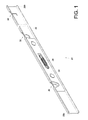
- the rail mounting structure 20 includes a rail member 22, an auxiliary member 24, and a resilient member 26.
- the rail member 22 has a first end portion 28a and a second end portion 28b opposite the first end portion 28a.
- the rail member 22 also includes a first mounting slot 30 and a second mounting slot 32, both of which are located between the first end portion 28a and the second end portion 28b.
- the rail member 22 further includes another mounting slot (e.g., a third mounting slot 34).
- the first mounting slot 30 and the second mounting slot 32 are adjacent to the first end portion 28a of the rail member 22 while the third mounting slot 34 is adjacent to the second end portion 28b of the rail member 22.
- the second mounting slot 32 and the third mounting slot 34 are of similar slot configurations different from that of the first mounting slot 30.
- the locations of the mounting slots are not limited to those disclosed herein, and each two adjacent mounting slots can be spaced by a predetermined distance depending on practical needs.
- the auxiliary member 24 is mounted to the rail member 22 and includes a first portion 36 and a second portion 38.
- the first portion 36 and the second portion 38 have an extended section 40 and an extended section 42 respectively.
- the auxiliary member 24 further includes at least one guide groove 44 and an elongated aperture 46.
- two guide grooves 44 are provided by way of example for use with two connecting elements 48 respectively, and the elongated aperture 46 is located between the two guide grooves 44.
- the auxiliary member 24 is movably connected to the rail member 22 by the two connecting elements 48.
- each connecting element 48 has a body 50 and a head 52 connected to the body 50, wherein the body 50 has a width W1 less than a width W2 of each guide groove 44 and the head 52 has a height H1 greater than a height H2 of each guide groove 44.
- the body 50 of each connecting element 48 can be passed through one of the guide grooves 44 and connected to the rail member 22, with the head 52 of the connecting element 48 blocked outside the guide groove 44, so that the auxiliary member 24 can be displaced relative to the rail member 22 within the limited range defined by the guide grooves 44.
- the resilient member 26 serves to provide a resilient force acting on the auxiliary member 24.
- the resilient member 26 is mounted between the rail member 22 and the auxiliary member 24.
- each of the rail member 22 and the auxiliary member 24 further includes a connecting portion 54, and the resilient member 26 is connected between the two connecting portions 54 and located in the elongated aperture 46 of the auxiliary member 24.
- the structural arrangement described above allows the auxiliary member 24 to be displaced relative to the rail member 22 in a stable manner.
- the auxiliary member 24 is kept at a predetermined position P1 relative to the rail member 22 by the resilient force of the resilient member 26. While the auxiliary member 24 is at the predetermined position P1, the first portion 36 of the auxiliary member 24 is adjacent to the first mounting slot 30, and the second portion 38 of the auxiliary member 24 is adjacent to the second mounting slot 32.
- the extended section 40 of the first portion 36 of the auxiliary member 24 extends in such a way that it covers the first mounting slot 30 partially, and the extended section 42 of the second portion 38 of the auxiliary member 24 extends in such a way that it covers the second mounting slot 32 partially.
- the first mounting slot 30 preferably includes an entrance portion 56 and a positioning portion 58.
- the entrance portion 56 extends downward from the top of the rail member 22 and forms an entrance.
- the positioning portion 58 extends substantially perpendicularly from the bottom of the entrance portion 56 for a distance D.
- the entrance portion 56 and the positioning portion 58 jointly constitute a generally J-shaped groove. More specifically, the extended section 40 of the first portion 36 of the auxiliary member 24 extends to a part of the positioning portion 58 of the first mounting slot 30.
- the second mounting slot 32 includes an entrance portion 60 and a positioning portion 62.
- the entrance portion 60 also extends downward from the top of the rail member 22 and forms an entrance.
- the positioning portion 62 is located at the bottom of the entrance portion 60.
- the entrance portion 60 and the positioning portion 62 jointly constitute a generally U-shaped groove.
- the extended section 42 of the second portion 38 of the auxiliary member 24 extends to a position between the entrance portion 60 and the positioning portion 62 of the second mounting slot 32.
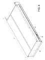
- the rail mounting structure 20 is applied to an object 64 such as the chassis of a piece of electronic equipment, a drawer, or the like.
- the object 64 has a length L1 and can be mounted to the rail member 22.
- FIG. 5A and FIG. 5B show how the object 64 is mounted to the rail member 22 of the rail mounting structure 20.
- the plural mounting members e.g., a first mounting member 68, a second mounting member 70, and a third mounting member 72 mounted on a sidewall 66 of the object 64 are respectively aligned with the first mounting slot 30, the second mounting slot 32, and the third mounting slot 34 of the rail member 22.
- the assembly process begins by putting the first mounting member 68 of the object 64 into the entrance portion 56 of the first mounting slot 30. After that, referring to FIG 5C and FIG.
- the first mounting member 68 of the object 64 is moved from the entrance portion 56 to the positioning portion 58 of the first mounting slot 30, during which time the first mounting member 68 pushes the first portion 36 of the auxiliary member 24 and overcomes the resilient force of the resilient member 26 such that the auxiliary member 24 is displaced relative to the rail member 22 from the aforesaid predetermined position P1 to a position P2.
- the object 64 is lowered, allowing the second mounting member 70 of the object 64 to enter the entrance portion 60 of the second mounting slot 32 of the rail member 22 and be mounted in the positioning portion 62 of the second mounting slot 32.
- the third mounting member 72 is mounted in the third mounting slot 34 in a similar manner.
- the object 64 is mounted to the rail member 22.
- the extended section 40 of the first portion 36 of the auxiliary member 24 is pressed against the first mounting member 68 by virtue of the resilient force of the resilient member 26, and vertically upward displacement of the first mounting member 68 is limited due to the shape of the first mounting slot 30.
- an engaging mechanism (not shown) can be provided between the third mounting member 72 and the rail member 22 to ensure that the object 64 is mounted securely.
- the engagement between the third mounting member 72 and the rail member 22 is released first. Then, a lifting force is applied to a portion of the object 64 that is adjacent to the third mounting member 72 to raise that portion of the object 64.
- the first mounting member 68 and the second mounting member 70 of the object 64 can be removed from the first mounting slot 30 and the second mounting slot 32 of the rail member 22 respectively, allowing the entire object 64 to be detached from the rail member 22 with ease.
- the rail mounting structure 20 is applied to another object 200, which has a length L2 different from the length L1 of the object 64 shown in FIG 4 , and which can be mounted to the rail member 22.
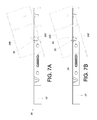
- FIG. 7A and FIG. 7B show how the object 200 is mounted to the rail member 22 of the rail mounting structure 20.
- one of the mounting members e.g., the mounting member 202
- the mounting member 202 of the object 200 is put into the entrance portion 60 of the second mounting slot 32 and, as shown in FIG. 7C and FIG 7D , is subsequently moved from the entrance portion 60 to the positioning portion 62 of the second mounting slot 32 such that the mounting member 202 is pressed against the extended section 42 of the second portion 38 of the auxiliary member 24.
- FIG. 8 shows the rail mounting structure 300 in another embodiment of the present invention.
- This embodiment is different from the previous one substantially in that the rail member 302 of the rail mounting structure 300 includes a contact portion 304, and that the resilient member 306 is connected to the auxiliary member 308 and pressed against the contact portion 304.
- the auxiliary member 308 is displaceable relative to the rail member 302 when pushed by an article (e.g., a mounting member of an object to be mounted to the rail member 302).
- FIG. 9 shows the rail mounting structure 400 in yet another embodiment of the present invention.
- This embodiment is different from the embodiment in FIG. 3 substantially in that the first portion 404 of the auxiliary member 402 includes an extended section 406 which is adjacent to, and on one side of, the positioning portion 410 of the first mounting slot 408.
- the second portion 412 of the auxiliary member 402 includes an extended section 414 adjacent to a position between the entrance portion 418 and the positioning portion 420 of the second mounting slot 416.
- the auxiliary member 402 is shown in FIG 9 as at a predetermined position P3.
- the first mounting member 424 of the object mounted to the rail member 430 of the rail mounting structure 400 includes a head section 426 and a body section 428 connected to the head section 426.
- the head section 426 has a greater diameter than the body section 428.
- the body section 428 can enter the first mounting slot 408.
- the head section 426 of the first mounting member 424 pushes the extended section 406 of the first portion 404 of the auxiliary member 402 such that the auxiliary member 402 is displaced relative to the rail member 430 from the predetermined position P3 to a position P4.
- the second mounting member 432 of the object is correspondingly mounted to the second mounting slot 416 of the rail member 430.
- the mounting member 434 includes a head section 436 and a body section 438 connected to the head section 436.
- the head section 436 has a greater diameter than the body section 438, and the body section 438 can enter the second mounting slot 416.
Landscapes
- Drawers Of Furniture (AREA)
Abstract
Description
- The present invention relates to a slide rail and more particularly to a rail mounting structure to which objects of different length specifications can be mounted.
- Generally, a slide rail assembly includes a first rail and a second rail, wherein the second rail can be longitudinally displaced relative to the first rail in order to be located at a retracted or extended position. Also, the second rail can be mounted with an object (e.g., a piece of electronic equipment, a drawer, or the like), and the way in which the object is mounted to the second rail may vary, depending on actual mounting requirements. For example,
U.S. Patent No. 6,938,967 B2 discloses a slide rail assembly having a rail member with a mounting slot, wherein the mounting slot is adapted to engage with a mounting post of an object. - The present invention relates to a rail mounting structure applicable to objects of different length specifications.
- According to one aspect of the present invention, a rail mounting structure includes a rail member, an auxiliary member, and a resilient member. The rail member includes a first mounting slot and a second mounting slot. The auxiliary member is movably mounted to the rail member and includes a first portion and a second portion. The resilient member provides a resilient force acting on the auxiliary member. The auxiliary member is kept at a predetermined position relative to the rail member by the resilient force of the resilient member. While the auxiliary member is at the predetermined position, the first portion of the auxiliary member is adjacent to the first mounting slot, and the second portion of the auxiliary member is adjacent to the second mounting slot.
- The first mounting slot preferably includes an entrance portion and a positioning portion, wherein the entrance portion of the first mounting slot extends downward from the top of the rail member and forms an entrance while the positioning portion of the first mounting slot extends substantially perpendicularly from the bottom of the entrance portion for a distance. The first portion of the auxiliary member preferably further includes an extended section which extends to a position corresponding to the positioning portion of the first mounting slot.
- The second mounting slot preferably includes an entrance portion and a positioning portion, wherein the entrance portion of the second mounting slot extends downward from the top of the rail member and forms an entrance while the positioning portion of the second mounting slot is located at the bottom of the entrance portion. The second portion of the auxiliary member preferably further includes an extended section which extends to a position corresponding to a position between the entrance portion and the positioning portion of the second mounting slot.
- Preferably, each of the rail member and the auxiliary member further includes a connecting portion, and the resilient member is connected between the two connecting portions. In addition, it is preferable that the auxiliary member further includes an elongated aperture, and that the resilient member is located in the elongated aperture.
- Preferably, the rail member further includes a contact portion, and the resilient member is connected to the auxiliary member and pressed against the contact portion.
- According to another aspect of the present invention, a rail mounting structure is provided for use with an object including a first mounting member and a second mounting member. The rail mounting structure includes a rail member, an auxiliary member, and a resilient member. The rail member includes a first mounting slot and a second mounting slot. The auxiliary member is movably mounted to the rail member and includes a first portion and a second portion, wherein the first portion is adjacent to the first mounting slot and the second portion is adjacent to the second mounting slot. The resilient member provides a resilient force acting on the auxiliary member. In the course in which the first mounting member of the object is mounted to the first mounting slot of the rail member, the first mounting member of the object pushes the first portion of the auxiliary member and overcomes the resilient force of the resilient member such that the auxiliary member is displaced to a position, allowing the second mounting member of the object to be mounted to the second mounting slot of the rail member.
- Preferably, the first mounting slot includes an entrance portion and a positioning portion; the entrance portion of the first mounting slot extends downward from the top of the rail member and forms an entrance; the positioning portion of the first mounting slot extends substantially perpendicularly from the bottom of the entrance portion for a distance; the first portion of the auxiliary member further includes an extended section which is adjacent to one side of the positioning portion of the first mounting slot; and the first mounting member further includes a head section and a body section connected to the head section. In the course in which the body section of the first mounting member is mounted to the positioning portion of the first mounting slot, the head section of the first mounting member pushes the extended section of the first portion of the auxiliary member and thereby displaces the auxiliary member.
- Preferably, the second mounting slot includes an entrance portion and a positioning portion, the entrance portion of the second mounting slot extends downward from the top of the rail member and forms an entrance, the positioning portion of the second mounting slot is located at the bottom of the entrance portion, and the second portion of the auxiliary member further includes an extended section which is adjacent to a position between the entrance portion and the positioning portion of the second mounting slot.
- According to yet another aspect of the present invention, a rail mounting structure includes a rail member, an auxiliary member, and a resilient member. The rail member includes a first mounting slot including an entrance portion and a positioning portion, wherein the entrance portion extends downward from a top of the rail member and forms an entrance, and the positioning portion extends substantially perpendicularly from a bottom of the entrance portion for a distance. The auxiliary member is movably mounted to the rail member and includes a first portion adjacent to the first mounting slot. The resilient member is configured to provide a resilient force acting on the auxiliary member.
- One of the advantageous features of applying the present invention is that the rail mounting structure can be applied to objects of different length specifications.
- The structure as well as a preferred mode of use and the advantages of the present invention will be best understood by referring to the following detailed description of some illustrative embodiments in conjunction with the accompanying drawings, in which:
-
FIG. 1 is a perspective view of the rail mounting structure in the first embodiment of the present invention; -
FIG. 2 is an exploded perspective view of the rail mounting structure in the first embodiment of the present invention; -
FIG. 3 is a side view of the rail mounting structure in the first embodiment of the present invention, showing in particular the structural arrangement of the rail member, the auxiliary member, and the resilient member; -
FIG. 4 is a perspective view in which the rail mounting structure in the first embodiment of the present invention is applied to an object capable of being mounted to the rail mounting structure; -
FIG. 5A shows how the object inFIG. 4 is mounted to the rail mounting structure in the first embodiment of the present invention; -
FIG. 5B further shows how the object inFIG. 4 is mounted to the rail mounting structure in the first embodiment of the present invention, or more particularly how the first mounting member of the object enters the first mounting slot of the rail member; -
FIG. 5C further shows how the object inFIG. 4 is mounted to the rail mounting structure in the first embodiment of the present invention, or more particularly how the first mounting member of the object is mounted to the positioning portion of the first mounting slot and how the auxiliary member is pushed by the first mounting member and therefore displaced to a different position; -
FIG. 5D further shows how the object inFIG. 4 is mounted to the rail mounting structure in the first embodiment of the present invention, wherein the object has been mounted to the rail member; -
FIG. 6 is a perspective view in which the rail mounting structure in the first embodiment of the present invention is applied to another object capable of being mounted to the rail mounting structure; -
FIG. 7A shows how the object inFIG. 6 is mounted to the rail mounting structure in the first embodiment of the present invention; -
FIG. 7B further shows how the object inFIG. 6 is mounted to the rail mounting structure in the first embodiment of the present invention, or more particularly how a mounting member of the object enters the second mounting slot of the rail member; -
FIG. 7C further shows how the object inFIG. 6 is mounted to the rail mounting structure in the first embodiment of the present invention, or more particularly how the aforesaid mounting member of the object is mounted to the positioning portion of the second mounting slot and blocked by the extended section of the second portion of the auxiliary member; -
FIG. 7D further shows how the object inFIG. 6 is mounted to the rail mounting structure in the first embodiment of the present invention, wherein the object has been mounted to the rail member; -
FIG. 8 is a side view of the rail mounting structure in the second embodiment of the present invention; -
FIG. 9 is a side view of the rail mounting structure in the third embodiment of the present invention; -
FIG. 10 shows how the first mounting slot and the second mounting slot of the rail mounting structure in the third embodiment of the present invention are mounted with a first mounting member and a second mounting member respectively; and -
FIG. 11 shows how the second mounting slot of the rail mounting structure in the third embodiment of the present invention is mounted with a mounting member. - Referring to
FIG 1 andFIG. 2 , therail mounting structure 20 according to an embodiment of the present invention includes arail member 22, anauxiliary member 24, and aresilient member 26. - The
rail member 22 has afirst end portion 28a and asecond end portion 28b opposite thefirst end portion 28a. Therail member 22 also includes a first mountingslot 30 and asecond mounting slot 32, both of which are located between thefirst end portion 28a and thesecond end portion 28b. In this embodiment, therail member 22 further includes another mounting slot (e.g., a third mounting slot 34). Thefirst mounting slot 30 and the second mountingslot 32 are adjacent to thefirst end portion 28a of therail member 22 while the third mountingslot 34 is adjacent to thesecond end portion 28b of therail member 22. Preferably, the second mountingslot 32 and the third mountingslot 34 are of similar slot configurations different from that of the first mountingslot 30. In practice, the locations of the mounting slots are not limited to those disclosed herein, and each two adjacent mounting slots can be spaced by a predetermined distance depending on practical needs. - As shown in
FIG. 2 andFIG 3 , theauxiliary member 24 is mounted to therail member 22 and includes afirst portion 36 and asecond portion 38. Thefirst portion 36 and thesecond portion 38 have an extendedsection 40 and anextended section 42 respectively. Preferably, theauxiliary member 24 further includes at least oneguide groove 44 and anelongated aperture 46. In this embodiment, twoguide grooves 44 are provided by way of example for use with two connectingelements 48 respectively, and theelongated aperture 46 is located between the twoguide grooves 44. Theauxiliary member 24 is movably connected to therail member 22 by the two connectingelements 48. More specifically, each connectingelement 48 has abody 50 and ahead 52 connected to thebody 50, wherein thebody 50 has a width W1 less than a width W2 of eachguide groove 44 and thehead 52 has a height H1 greater than a height H2 of eachguide groove 44. With this arrangement, thebody 50 of each connectingelement 48 can be passed through one of theguide grooves 44 and connected to therail member 22, with thehead 52 of the connectingelement 48 blocked outside theguide groove 44, so that theauxiliary member 24 can be displaced relative to therail member 22 within the limited range defined by theguide grooves 44. Theresilient member 26 serves to provide a resilient force acting on theauxiliary member 24. Here, theresilient member 26 is mounted between therail member 22 and theauxiliary member 24. For example, each of therail member 22 and theauxiliary member 24 further includes a connectingportion 54, and theresilient member 26 is connected between the two connectingportions 54 and located in theelongated aperture 46 of theauxiliary member 24. The structural arrangement described above allows theauxiliary member 24 to be displaced relative to therail member 22 in a stable manner. - As shown in
FIG. 3 , theauxiliary member 24 is kept at a predetermined position P1 relative to therail member 22 by the resilient force of theresilient member 26. While theauxiliary member 24 is at the predetermined position P1, thefirst portion 36 of theauxiliary member 24 is adjacent to the first mountingslot 30, and thesecond portion 38 of theauxiliary member 24 is adjacent to the second mountingslot 32. In a preferred embodiment, theextended section 40 of thefirst portion 36 of theauxiliary member 24 extends in such a way that it covers the first mountingslot 30 partially, and theextended section 42 of thesecond portion 38 of theauxiliary member 24 extends in such a way that it covers the second mountingslot 32 partially. - The
first mounting slot 30 preferably includes anentrance portion 56 and apositioning portion 58. Theentrance portion 56 extends downward from the top of therail member 22 and forms an entrance. The positioningportion 58 extends substantially perpendicularly from the bottom of theentrance portion 56 for a distance D. Theentrance portion 56 and thepositioning portion 58 jointly constitute a generally J-shaped groove. More specifically, theextended section 40 of thefirst portion 36 of theauxiliary member 24 extends to a part of thepositioning portion 58 of the first mountingslot 30. Thesecond mounting slot 32, on the other hand, includes anentrance portion 60 and apositioning portion 62. Theentrance portion 60 also extends downward from the top of therail member 22 and forms an entrance. The positioningportion 62 is located at the bottom of theentrance portion 60. Theentrance portion 60 and thepositioning portion 62 jointly constitute a generally U-shaped groove. Theextended section 42 of thesecond portion 38 of theauxiliary member 24 extends to a position between theentrance portion 60 and thepositioning portion 62 of the second mountingslot 32. - In
FIG 4 , therail mounting structure 20 is applied to anobject 64 such as the chassis of a piece of electronic equipment, a drawer, or the like. Theobject 64 has a length L1 and can be mounted to therail member 22. -
FIG. 5A and FIG. 5B show how theobject 64 is mounted to therail member 22 of therail mounting structure 20. When it is desired to mount theobject 64 to therail member 22, the plural mounting members (e.g., a first mountingmember 68, a second mountingmember 70, and a third mounting member 72) mounted on asidewall 66 of theobject 64 are respectively aligned with the first mountingslot 30, the second mountingslot 32, and the third mountingslot 34 of therail member 22. For example, the assembly process begins by putting the first mountingmember 68 of theobject 64 into theentrance portion 56 of the first mountingslot 30. After that, referring toFIG 5C and FIG. 5D , the first mountingmember 68 of theobject 64 is moved from theentrance portion 56 to thepositioning portion 58 of the first mountingslot 30, during which time the first mountingmember 68 pushes thefirst portion 36 of theauxiliary member 24 and overcomes the resilient force of theresilient member 26 such that theauxiliary member 24 is displaced relative to therail member 22 from the aforesaid predetermined position P1 to a position P2. On the other hand, theobject 64 is lowered, allowing the second mountingmember 70 of theobject 64 to enter theentrance portion 60 of the second mountingslot 32 of therail member 22 and be mounted in thepositioning portion 62 of the second mountingslot 32. The third mountingmember 72 is mounted in the third mountingslot 34 in a similar manner. Thus, theobject 64 is mounted to therail member 22. It is worth mentioning that, once theauxiliary member 24 is displaced to the position P2, theextended section 40 of thefirst portion 36 of theauxiliary member 24 is pressed against the first mountingmember 68 by virtue of the resilient force of theresilient member 26, and vertically upward displacement of the first mountingmember 68 is limited due to the shape of the first mountingslot 30. In practice, an engaging mechanism (not shown) can be provided between the third mountingmember 72 and therail member 22 to ensure that theobject 64 is mounted securely. When it is desired to remove theobject 64 from therail member 22, the engagement between the third mountingmember 72 and therail member 22 is released first. Then, a lifting force is applied to a portion of theobject 64 that is adjacent to the third mountingmember 72 to raise that portion of theobject 64. Once theobject 64 forms a proper inclination angle with therail member 22, the first mountingmember 68 and the second mountingmember 70 of theobject 64 can be removed from the first mountingslot 30 and the second mountingslot 32 of therail member 22 respectively, allowing theentire object 64 to be detached from therail member 22 with ease. - In
FIG 6 , therail mounting structure 20 is applied to anotherobject 200, which has a length L2 different from the length L1 of theobject 64 shown inFIG 4 , and which can be mounted to therail member 22. -
FIG. 7A and FIG. 7B show how theobject 200 is mounted to therail member 22 of therail mounting structure 20. When it is desired to mount theobject 200 to therail member 22, one of the mounting members (e.g., the mounting member 202) on a sidewall of theobject 200 is aligned with the second mountingslot 32 of therail member 22. More specifically, the mountingmember 202 of theobject 200 is put into theentrance portion 60 of the second mountingslot 32 and, as shown inFIG. 7C and FIG 7D , is subsequently moved from theentrance portion 60 to thepositioning portion 62 of the second mountingslot 32 such that the mountingmember 202 is pressed against theextended section 42 of thesecond portion 38 of theauxiliary member 24. Afterward, by lowering theobject 200, another mountingmember 204 of theobject 200 is mounted in the third mountingslot 34 of therail member 22. Thanks to the resilient force of theresilient member 26, theextended section 42 of thesecond portion 38 of theauxiliary member 24 is now pressed against the mountingmember 202, and theobject 200 is thus mounted to therail member 22. As with the first mountingslot 30 of therail member 22 and the first mountingmember 68 in the previous case, the engagement between the mountingmember 202 of theobject 200 and theextended section 42 of thesecond portion 38 of theauxiliary member 24 limits vertically upward displacement of the mountingmember 202, thereby ensuring that theobject 200 is mounted securely. Detachment of theobject 200 can be carried out in a way similar to that of theobject 64 and therefore is not described repeatedly. -
FIG. 8 shows therail mounting structure 300 in another embodiment of the present invention. This embodiment is different from the previous one substantially in that therail member 302 of therail mounting structure 300 includes acontact portion 304, and that theresilient member 306 is connected to theauxiliary member 308 and pressed against thecontact portion 304. Thus, theauxiliary member 308 is displaceable relative to therail member 302 when pushed by an article (e.g., a mounting member of an object to be mounted to the rail member 302). -
FIG. 9 shows therail mounting structure 400 in yet another embodiment of the present invention. This embodiment is different from the embodiment inFIG. 3 substantially in that thefirst portion 404 of theauxiliary member 402 includes anextended section 406 which is adjacent to, and on one side of, thepositioning portion 410 of thefirst mounting slot 408. On the other hand, thesecond portion 412 of theauxiliary member 402 includes anextended section 414 adjacent to a position between theentrance portion 418 and thepositioning portion 420 of thesecond mounting slot 416. Theauxiliary member 402 is shown inFIG 9 as at a predetermined position P3. - Referring to
FIG 10 , the first mountingmember 424 of the object mounted to therail member 430 of therail mounting structure 400 includes ahead section 426 and abody section 428 connected to thehead section 426. Thehead section 426 has a greater diameter than thebody section 428. Thebody section 428 can enter thefirst mounting slot 408. In the course in which thebody section 428 of the first mountingmember 424 of the object is mounted to thepositioning portion 410 of thefirst mounting slot 408, thehead section 426 of the first mountingmember 424 pushes theextended section 406 of thefirst portion 404 of theauxiliary member 402 such that theauxiliary member 402 is displaced relative to therail member 430 from the predetermined position P3 to a position P4. The second mountingmember 432 of the object, on the other hand, is correspondingly mounted to thesecond mounting slot 416 of therail member 430. - As shown in
FIG. 11 , when therail mounting structure 400 is applied to another object, one of the mounting members (e.g., the mounting member 434) of this object is correspondingly mounted to thesecond mounting slot 416 of therail member 430. More specifically, the mountingmember 434 includes ahead section 436 and abody section 438 connected to thehead section 436. Thehead section 436 has a greater diameter than thebody section 438, and thebody section 438 can enter thesecond mounting slot 416. Once thebody section 438 of the mountingmember 434 of the object is mounted to thepositioning portion 420 of thesecond mounting slot 416, a portion of thehead section 436 of the mountingmember 434 is blocked by theextended section 414 of thesecond portion 412 of theauxiliary member 402. - While the present invention has been disclosed through the foregoing preferred embodiments, the embodiments are not intended to be restrictive of the present invention. The scope of patent protection sought by the applicant is defined by the appended claims.
Claims (12)
- A rail mounting structure (20, 300, 400), comprising:a rail member (22, 302, 430) comprising a first mounting slot (30, 408);an auxiliary member (24, 308, 402) movably mounted to the rail member (22, 302, 430), the auxiliary member (24, 308, 402) comprising a first portion (36, 404) adjacent to the first mounting slot (30, 408); anda resilient member (26, 306) for providing a resilient force acting on the auxiliary member (24, 308, 402).
- The rail mounting structure (20, 300, 400) as claimed in claim 1, wherein the first mounting slot (30, 408) comprises an entrance portion (56) and a positioning portion (58, 410), the entrance portion (56) extends downward from a top of the rail member (22, 302, 430) and forms an entrance, and the positioning portion (58, 410) extends substantially perpendicularly from a bottom of the entrance portion (56) for a distance (D).
- The rail mounting structure (20, 300, 400) as claimed in claim 1, wherein the rail member (22, 302, 430) further comprises a second mounting slot (32, 416), the auxiliary member (24, 308, 402) further comprises a second portion (38, 412), and the resilient force keeps the auxiliary member (24, 308, 402) at a predetermined position (P1, P3) relative to the rail member (22, 302, 430) where the first portion (36, 404) and the second portion (38, 412) of the auxiliary member (24, 308, 402) are adjacent to the first mounting slot (30, 408) and the second mounting slot (32, 416) respectively.
- The rail mounting structure (20, 300, 400) as claimed in claim 3, wherein the first mounting slot (30, 408) comprises an entrance portion (56) and a positioning portion (58, 410), the entrance portion (56) of the first mounting slot (30, 408) extends downward from a top of the rail member (22, 302, 430) and forms an entrance, and the positioning portion (58, 410) of the first mounting slot (30, 408) extends substantially perpendicularly from a bottom of the entrance portion (56) for a distance (D).
- The rail mounting structure (20, 300, 400) as claimed in claim 4, wherein the first portion (36, 404) of the auxiliary member (24, 308, 402) further comprises an extended section (40, 406) extending to a position corresponding to the positioning portion (58, 410) of the first mounting slot (30, 408).
- The rail mounting structure (20, 300, 400) as claimed in claim 3, wherein the second mounting slot (32, 416) comprises an entrance portion (60, 418) and a positioning portion (62, 420), the entrance portion (60, 418) of the second mounting slot (32, 416) extends downward from a top of the rail member (22, 302, 430) and forms an entrance, the positioning portion (62, 420) of the second mounting slot (32, 416) is located at a bottom of the entrance portion (60, 418), and the second portion (38, 412) of the auxiliary member (24, 308, 402) further comprises an extended section (42, 414) extending to a position corresponding to a position between the entrance portion (60, 418) and the positioning portion (62, 420) of the second mounting slot (32, 416).
- The rail mounting structure (20, 400) as claimed in claim 3, wherein each of the rail member (22, 430) and the auxiliary member (24, 402) further comprises a connecting portion (54), and the resilient member (26) is connected between the two connecting portions (54).
- The rail mounting structure (20, 400) as claimed in claim 7, wherein the auxiliary member (24, 402) further comprises an elongated aperture (46), and the resilient member (26) is located in the elongated aperture (46).
- The rail mounting structure (300) as claimed in claim 3, wherein the rail member (302) further comprises a contact portion (304), and the resilient member (306) is connected to the auxiliary member (308) and pressed against the contact portion (304).
- The rail mounting structure (20, 300, 400) as claimed in claim 1, wherein the rail mounting structure (20, 300, 400) is applicable to an object (64) comprising a first mounting member (68, 424) and a second mounting member (70, 432); the rail member (22, 302, 430) further comprises a second mounting slot (32, 416), the auxiliary member (24, 308, 402) further comprises a second portion (38, 412), and the first portion (36, 404) and the second portion (38, 412) of the auxiliary member (24, 308, 402) are adjacent to the first mounting slot (30, 408) and the second mounting slot (32, 416) respectively; and wherein while being mounted to the first mounting slot (30, 408) of the rail member (22, 302, 430), the first mounting member (68, 424) of the object (64) pushes the first portion (36, 404) of the auxiliary member (24, 308, 402) and overcomes the resilient force of the resilient member (26, 306) such that the auxiliary member (24, 308, 402) is displaced to a position (P2, P4), allowing the second mounting member (70, 432) of the object (64) to be mounted to the second mounting slot (32, 416) of the rail member (22, 302, 430).
- The rail mounting structure (400) as claimed in claim 10, wherein the first mounting slot (408) comprises an entrance portion and a positioning portion (410); the entrance portion of the first mounting slot (408) extends downward from a top of the rail member (430) and forms an entrance; the positioning portion (410) of the first mounting slot (408) extends substantially perpendicularly from a bottom of the entrance portion for a distance; the first portion (404) of the auxiliary member (402) further comprises an extended section (406) adjacent to one side of the positioning portion (410) of the first mounting slot (408); and the first mounting member (424) further comprises a head section (426) and a body section (428) connected to the head section (426) such that, while the body section (428) of the first mounting member (424) is being mounted to the positioning portion (410) of the first mounting slot (408), the head section (426) of the first mounting member (424) pushes the extended section (406) of the first portion (404) of the auxiliary member (402) and thereby displaces the auxiliary member (402).
- The rail mounting structure (400) as claimed in claim 10, wherein the second mounting slot (416) comprises an entrance portion (418) and a positioning portion (420), the entrance portion (418) of the second mounting slot (416) extends downward from a top of the rail member (430) and forms an entrance, the positioning portion (420) of the second mounting slot (416) is located at a bottom of the entrance portion (418), and the second portion (412) of the auxiliary member (402) further comprises an extended section (414) adjacent to a position between the entrance portion (418) and the positioning portion (420) of the second mounting slot (416).
Priority Applications (1)
| Application Number | Priority Date | Filing Date | Title |
|---|---|---|---|
| EP15159153.4A EP3069633B1 (en) | 2015-03-16 | 2015-03-16 | Rail mounting structure |
Applications Claiming Priority (1)
| Application Number | Priority Date | Filing Date | Title |
|---|---|---|---|
| EP15159153.4A EP3069633B1 (en) | 2015-03-16 | 2015-03-16 | Rail mounting structure |
Publications (2)
| Publication Number | Publication Date |
|---|---|
| EP3069633A1 true EP3069633A1 (en) | 2016-09-21 |
| EP3069633B1 EP3069633B1 (en) | 2018-10-10 |
Family
ID=52672201
Family Applications (1)
| Application Number | Title | Priority Date | Filing Date |
|---|---|---|---|
| EP15159153.4A Active EP3069633B1 (en) | 2015-03-16 | 2015-03-16 | Rail mounting structure |
Country Status (1)
| Country | Link |
|---|---|
| EP (1) | EP3069633B1 (en) |
Citations (3)
| Publication number | Priority date | Publication date | Assignee | Title |
|---|---|---|---|---|
| US6938967B2 (en) | 2001-12-12 | 2005-09-06 | Pentair Electronic Packaging Co. | Telescoping slide assembly |
| US7513581B1 (en) * | 2007-06-07 | 2009-04-07 | Central Industrial Supply Company | Chassis lock for a drawer slide |
| US20130044416A1 (en) * | 2011-08-16 | 2013-02-21 | Hon Hai Precision Industry Co., Ltd. | Slide assembly |
-
2015
- 2015-03-16 EP EP15159153.4A patent/EP3069633B1/en active Active
Patent Citations (3)
| Publication number | Priority date | Publication date | Assignee | Title |
|---|---|---|---|---|
| US6938967B2 (en) | 2001-12-12 | 2005-09-06 | Pentair Electronic Packaging Co. | Telescoping slide assembly |
| US7513581B1 (en) * | 2007-06-07 | 2009-04-07 | Central Industrial Supply Company | Chassis lock for a drawer slide |
| US20130044416A1 (en) * | 2011-08-16 | 2013-02-21 | Hon Hai Precision Industry Co., Ltd. | Slide assembly |
Also Published As
| Publication number | Publication date |
|---|---|
| EP3069633B1 (en) | 2018-10-10 |
Similar Documents
| Publication | Publication Date | Title |
|---|---|---|
| US9125489B2 (en) | Fixing device for a slide assembly | |
| US9629459B2 (en) | Slide rail assembly | |
| US9681749B2 (en) | Slide rail assembly | |
| US9480183B2 (en) | Slide rail assembly | |
| US20160278522A1 (en) | Slide rail assembly | |
| US9504181B2 (en) | Slide rail assembly | |
| CN104873012A (en) | Slide Rail And Equipment Mounting Rack | |
| US20180098626A1 (en) | Bracket device | |
| EP3199061B1 (en) | Slide rail assembly | |
| US20090283652A1 (en) | Adjustable bracket for a slide assembly | |
| US20160097229A1 (en) | Slide rail assembly | |
| US20160198855A1 (en) | Slide rail assembly and mounting device thereof | |
| EP3176351A1 (en) | Slide rail assembly and locking device thereof | |
| EP3197252A1 (en) | Slide rail assembly and guiding mechanism thereof | |
| US9642279B2 (en) | Rail mounting structure | |
| US9861197B2 (en) | Slide rail assembly | |
| KR20200088755A (en) | Fixing apparatus for easy detachable on din rail | |
| EP3310033B1 (en) | Slide rail assembly | |
| EP3073811B1 (en) | Slide rail assembly | |
| EP3069633A1 (en) | Rail mounting structure | |
| US9755687B2 (en) | Housing mounting mechanism for portable electronic device | |
| EP3116291A1 (en) | Slide rail mounting mechanism | |
| EP3045074A1 (en) | Slide rail assembly and mounting device thereof | |
| EP3005901A1 (en) | Slide rail assembly | |
| CN105725545B (en) | Slide rail installation mechanism |
Legal Events
| Date | Code | Title | Description |
|---|---|---|---|
| PUAI | Public reference made under article 153(3) epc to a published international application that has entered the european phase |
Free format text: ORIGINAL CODE: 0009012 |
|
| 17P | Request for examination filed |
Effective date: 20160304 |
|
| AK | Designated contracting states |
Kind code of ref document: A1 Designated state(s): AL AT BE BG CH CY CZ DE DK EE ES FI FR GB GR HR HU IE IS IT LI LT LU LV MC MK MT NL NO PL PT RO RS SE SI SK SM TR |
|
| AX | Request for extension of the european patent |
Extension state: BA ME |
|
| REG | Reference to a national code |
Ref country code: DE Ref legal event code: R079 Ref document number: 602015017703 Country of ref document: DE Free format text: PREVIOUS MAIN CLASS: A47B0088040000 Ipc: A47B0088400000 |
|
| STAA | Information on the status of an ep patent application or granted ep patent |
Free format text: STATUS: EXAMINATION IS IN PROGRESS |
|
| RIC1 | Information provided on ipc code assigned before grant |
Ipc: A47B 88/427 20170101ALI20170817BHEP Ipc: A47B 88/40 20170101AFI20170817BHEP |
|
| 17Q | First examination report despatched |
Effective date: 20170905 |
|
| GRAP | Despatch of communication of intention to grant a patent |
Free format text: ORIGINAL CODE: EPIDOSNIGR1 |
|
| STAA | Information on the status of an ep patent application or granted ep patent |
Free format text: STATUS: GRANT OF PATENT IS INTENDED |
|
| INTG | Intention to grant announced |
Effective date: 20180509 |
|
| GRAS | Grant fee paid |
Free format text: ORIGINAL CODE: EPIDOSNIGR3 |
|
| GRAA | (expected) grant |
Free format text: ORIGINAL CODE: 0009210 |
|
| STAA | Information on the status of an ep patent application or granted ep patent |
Free format text: STATUS: THE PATENT HAS BEEN GRANTED |
|
| AK | Designated contracting states |
Kind code of ref document: B1 Designated state(s): AL AT BE BG CH CY CZ DE DK EE ES FI FR GB GR HR HU IE IS IT LI LT LU LV MC MK MT NL NO PL PT RO RS SE SI SK SM TR |
|
| REG | Reference to a national code |
Ref country code: GB Ref legal event code: FG4D |
|
| REG | Reference to a national code |
Ref country code: CH Ref legal event code: EP Ref country code: AT Ref legal event code: REF Ref document number: 1050227 Country of ref document: AT Kind code of ref document: T Effective date: 20181015 |
|
| REG | Reference to a national code |
Ref country code: IE Ref legal event code: FG4D |
|
| REG | Reference to a national code |
Ref country code: DE Ref legal event code: R096 Ref document number: 602015017703 Country of ref document: DE |
|
| REG | Reference to a national code |
Ref country code: NL Ref legal event code: MP Effective date: 20181010 |
|
| REG | Reference to a national code |
Ref country code: LT Ref legal event code: MG4D |
|
| REG | Reference to a national code |
Ref country code: AT Ref legal event code: MK05 Ref document number: 1050227 Country of ref document: AT Kind code of ref document: T Effective date: 20181010 |
|
| PG25 | Lapsed in a contracting state [announced via postgrant information from national office to epo] |
Ref country code: NL Free format text: LAPSE BECAUSE OF FAILURE TO SUBMIT A TRANSLATION OF THE DESCRIPTION OR TO PAY THE FEE WITHIN THE PRESCRIBED TIME-LIMIT Effective date: 20181010 |
|
| PG25 | Lapsed in a contracting state [announced via postgrant information from national office to epo] |
Ref country code: FI Free format text: LAPSE BECAUSE OF FAILURE TO SUBMIT A TRANSLATION OF THE DESCRIPTION OR TO PAY THE FEE WITHIN THE PRESCRIBED TIME-LIMIT Effective date: 20181010 Ref country code: IS Free format text: LAPSE BECAUSE OF FAILURE TO SUBMIT A TRANSLATION OF THE DESCRIPTION OR TO PAY THE FEE WITHIN THE PRESCRIBED TIME-LIMIT Effective date: 20190210 Ref country code: NO Free format text: LAPSE BECAUSE OF FAILURE TO SUBMIT A TRANSLATION OF THE DESCRIPTION OR TO PAY THE FEE WITHIN THE PRESCRIBED TIME-LIMIT Effective date: 20190110 Ref country code: HR Free format text: LAPSE BECAUSE OF FAILURE TO SUBMIT A TRANSLATION OF THE DESCRIPTION OR TO PAY THE FEE WITHIN THE PRESCRIBED TIME-LIMIT Effective date: 20181010 Ref country code: PL Free format text: LAPSE BECAUSE OF FAILURE TO SUBMIT A TRANSLATION OF THE DESCRIPTION OR TO PAY THE FEE WITHIN THE PRESCRIBED TIME-LIMIT Effective date: 20181010 Ref country code: BG Free format text: LAPSE BECAUSE OF FAILURE TO SUBMIT A TRANSLATION OF THE DESCRIPTION OR TO PAY THE FEE WITHIN THE PRESCRIBED TIME-LIMIT Effective date: 20190110 Ref country code: LT Free format text: LAPSE BECAUSE OF FAILURE TO SUBMIT A TRANSLATION OF THE DESCRIPTION OR TO PAY THE FEE WITHIN THE PRESCRIBED TIME-LIMIT Effective date: 20181010 Ref country code: ES Free format text: LAPSE BECAUSE OF FAILURE TO SUBMIT A TRANSLATION OF THE DESCRIPTION OR TO PAY THE FEE WITHIN THE PRESCRIBED TIME-LIMIT Effective date: 20181010 Ref country code: AT Free format text: LAPSE BECAUSE OF FAILURE TO SUBMIT A TRANSLATION OF THE DESCRIPTION OR TO PAY THE FEE WITHIN THE PRESCRIBED TIME-LIMIT Effective date: 20181010 Ref country code: LV Free format text: LAPSE BECAUSE OF FAILURE TO SUBMIT A TRANSLATION OF THE DESCRIPTION OR TO PAY THE FEE WITHIN THE PRESCRIBED TIME-LIMIT Effective date: 20181010 |
|
| PG25 | Lapsed in a contracting state [announced via postgrant information from national office to epo] |
Ref country code: PT Free format text: LAPSE BECAUSE OF FAILURE TO SUBMIT A TRANSLATION OF THE DESCRIPTION OR TO PAY THE FEE WITHIN THE PRESCRIBED TIME-LIMIT Effective date: 20190210 Ref country code: AL Free format text: LAPSE BECAUSE OF FAILURE TO SUBMIT A TRANSLATION OF THE DESCRIPTION OR TO PAY THE FEE WITHIN THE PRESCRIBED TIME-LIMIT Effective date: 20181010 Ref country code: RS Free format text: LAPSE BECAUSE OF FAILURE TO SUBMIT A TRANSLATION OF THE DESCRIPTION OR TO PAY THE FEE WITHIN THE PRESCRIBED TIME-LIMIT Effective date: 20181010 Ref country code: SE Free format text: LAPSE BECAUSE OF FAILURE TO SUBMIT A TRANSLATION OF THE DESCRIPTION OR TO PAY THE FEE WITHIN THE PRESCRIBED TIME-LIMIT Effective date: 20181010 |
|
| REG | Reference to a national code |
Ref country code: DE Ref legal event code: R097 Ref document number: 602015017703 Country of ref document: DE |
|
| PG25 | Lapsed in a contracting state [announced via postgrant information from national office to epo] |
Ref country code: IT Free format text: LAPSE BECAUSE OF FAILURE TO SUBMIT A TRANSLATION OF THE DESCRIPTION OR TO PAY THE FEE WITHIN THE PRESCRIBED TIME-LIMIT Effective date: 20181010 Ref country code: DK Free format text: LAPSE BECAUSE OF FAILURE TO SUBMIT A TRANSLATION OF THE DESCRIPTION OR TO PAY THE FEE WITHIN THE PRESCRIBED TIME-LIMIT Effective date: 20181010 Ref country code: CZ Free format text: LAPSE BECAUSE OF FAILURE TO SUBMIT A TRANSLATION OF THE DESCRIPTION OR TO PAY THE FEE WITHIN THE PRESCRIBED TIME-LIMIT Effective date: 20181010 |
|
| PLBE | No opposition filed within time limit |
Free format text: ORIGINAL CODE: 0009261 |
|
| STAA | Information on the status of an ep patent application or granted ep patent |
Free format text: STATUS: NO OPPOSITION FILED WITHIN TIME LIMIT |
|
| PG25 | Lapsed in a contracting state [announced via postgrant information from national office to epo] |
Ref country code: RO Free format text: LAPSE BECAUSE OF FAILURE TO SUBMIT A TRANSLATION OF THE DESCRIPTION OR TO PAY THE FEE WITHIN THE PRESCRIBED TIME-LIMIT Effective date: 20181010 Ref country code: SK Free format text: LAPSE BECAUSE OF FAILURE TO SUBMIT A TRANSLATION OF THE DESCRIPTION OR TO PAY THE FEE WITHIN THE PRESCRIBED TIME-LIMIT Effective date: 20181010 Ref country code: SM Free format text: LAPSE BECAUSE OF FAILURE TO SUBMIT A TRANSLATION OF THE DESCRIPTION OR TO PAY THE FEE WITHIN THE PRESCRIBED TIME-LIMIT Effective date: 20181010 Ref country code: EE Free format text: LAPSE BECAUSE OF FAILURE TO SUBMIT A TRANSLATION OF THE DESCRIPTION OR TO PAY THE FEE WITHIN THE PRESCRIBED TIME-LIMIT Effective date: 20181010 |
|
| 26N | No opposition filed |
Effective date: 20190711 |
|
| PG25 | Lapsed in a contracting state [announced via postgrant information from national office to epo] |
Ref country code: SI Free format text: LAPSE BECAUSE OF FAILURE TO SUBMIT A TRANSLATION OF THE DESCRIPTION OR TO PAY THE FEE WITHIN THE PRESCRIBED TIME-LIMIT Effective date: 20181010 Ref country code: MC Free format text: LAPSE BECAUSE OF FAILURE TO SUBMIT A TRANSLATION OF THE DESCRIPTION OR TO PAY THE FEE WITHIN THE PRESCRIBED TIME-LIMIT Effective date: 20181010 |
|
| REG | Reference to a national code |
Ref country code: CH Ref legal event code: PL |
|
| PG25 | Lapsed in a contracting state [announced via postgrant information from national office to epo] |
Ref country code: LU Free format text: LAPSE BECAUSE OF NON-PAYMENT OF DUE FEES Effective date: 20190316 |
|
| REG | Reference to a national code |
Ref country code: BE Ref legal event code: MM Effective date: 20190331 |
|
| PG25 | Lapsed in a contracting state [announced via postgrant information from national office to epo] |
Ref country code: CH Free format text: LAPSE BECAUSE OF NON-PAYMENT OF DUE FEES Effective date: 20190331 Ref country code: LI Free format text: LAPSE BECAUSE OF NON-PAYMENT OF DUE FEES Effective date: 20190331 |
|
| PG25 | Lapsed in a contracting state [announced via postgrant information from national office to epo] |
Ref country code: BE Free format text: LAPSE BECAUSE OF NON-PAYMENT OF DUE FEES Effective date: 20190331 Ref country code: FR Free format text: LAPSE BECAUSE OF NON-PAYMENT OF DUE FEES Effective date: 20190331 |
|
| PG25 | Lapsed in a contracting state [announced via postgrant information from national office to epo] |
Ref country code: TR Free format text: LAPSE BECAUSE OF FAILURE TO SUBMIT A TRANSLATION OF THE DESCRIPTION OR TO PAY THE FEE WITHIN THE PRESCRIBED TIME-LIMIT Effective date: 20181010 |
|
| PG25 | Lapsed in a contracting state [announced via postgrant information from national office to epo] |
Ref country code: MT Free format text: LAPSE BECAUSE OF NON-PAYMENT OF DUE FEES Effective date: 20190316 |
|
| PG25 | Lapsed in a contracting state [announced via postgrant information from national office to epo] |
Ref country code: CY Free format text: LAPSE BECAUSE OF FAILURE TO SUBMIT A TRANSLATION OF THE DESCRIPTION OR TO PAY THE FEE WITHIN THE PRESCRIBED TIME-LIMIT Effective date: 20181010 |
|
| PG25 | Lapsed in a contracting state [announced via postgrant information from national office to epo] |
Ref country code: GR Free format text: LAPSE BECAUSE OF FAILURE TO SUBMIT A TRANSLATION OF THE DESCRIPTION OR TO PAY THE FEE WITHIN THE PRESCRIBED TIME-LIMIT Effective date: 20181010 |
|
| PG25 | Lapsed in a contracting state [announced via postgrant information from national office to epo] |
Ref country code: HU Free format text: LAPSE BECAUSE OF FAILURE TO SUBMIT A TRANSLATION OF THE DESCRIPTION OR TO PAY THE FEE WITHIN THE PRESCRIBED TIME-LIMIT; INVALID AB INITIO Effective date: 20150316 |
|
| PG25 | Lapsed in a contracting state [announced via postgrant information from national office to epo] |
Ref country code: MK Free format text: LAPSE BECAUSE OF FAILURE TO SUBMIT A TRANSLATION OF THE DESCRIPTION OR TO PAY THE FEE WITHIN THE PRESCRIBED TIME-LIMIT Effective date: 20181010 |
|
| PGFP | Annual fee paid to national office [announced via postgrant information from national office to epo] |
Ref country code: GB Payment date: 20260108 Year of fee payment: 12 |
|
| PGFP | Annual fee paid to national office [announced via postgrant information from national office to epo] |
Ref country code: DE Payment date: 20260109 Year of fee payment: 12 Ref country code: IE Payment date: 20260108 Year of fee payment: 12 |