EP3069593A1 - Charging equipment for moving robot and controlling method thereof - Google Patents
Charging equipment for moving robot and controlling method thereof Download PDFInfo
- Publication number
- EP3069593A1 EP3069593A1 EP16160413.7A EP16160413A EP3069593A1 EP 3069593 A1 EP3069593 A1 EP 3069593A1 EP 16160413 A EP16160413 A EP 16160413A EP 3069593 A1 EP3069593 A1 EP 3069593A1
- Authority
- EP
- European Patent Office
- Prior art keywords
- moving robot
- unit
- charging equipment
- supporting unit
- robot
- Prior art date
- Legal status (The legal status is an assumption and is not a legal conclusion. Google has not performed a legal analysis and makes no representation as to the accuracy of the status listed.)
- Granted
Links
Images





Classifications
-
- H—ELECTRICITY
- H02—GENERATION; CONVERSION OR DISTRIBUTION OF ELECTRIC POWER
- H02J—ELECTRIC POWER NETWORKS; CIRCUIT ARRANGEMENTS OR SYSTEMS FOR SUPPLYING OR DISTRIBUTING ELECTRIC POWER; SYSTEMS FOR STORING ELECTRIC ENERGY
- H02J7/00—Circuit arrangements for charging or discharging batteries or for supplying loads from batteries
- H02J7/70—Circuit arrangements for charging or discharging batteries or for supplying loads from batteries characterised by the mechanical construction
-
- A—HUMAN NECESSITIES
- A01—AGRICULTURE; FORESTRY; ANIMAL HUSBANDRY; HUNTING; TRAPPING; FISHING
- A01D—HARVESTING; MOWING
- A01D34/00—Mowers; Mowing apparatus of harvesters
- A01D34/006—Control or measuring arrangements
- A01D34/008—Control or measuring arrangements for automated or remotely controlled operation
-
- A—HUMAN NECESSITIES
- A01—AGRICULTURE; FORESTRY; ANIMAL HUSBANDRY; HUNTING; TRAPPING; FISHING
- A01D—HARVESTING; MOWING
- A01D69/00—Driving mechanisms or parts thereof for harvesters or mowers
- A01D69/02—Driving mechanisms or parts thereof for harvesters or mowers electric
-
- G—PHYSICS
- G05—CONTROLLING; REGULATING
- G05D—SYSTEMS FOR CONTROLLING OR REGULATING NON-ELECTRIC VARIABLES
- G05D1/00—Control of position, course, altitude or attitude of land, water, air or space vehicles, e.g. using automatic pilots
- G05D1/02—Control of position or course in two dimensions
- G05D1/021—Control of position or course in two dimensions specially adapted to land vehicles
- G05D1/0212—Control of position or course in two dimensions specially adapted to land vehicles with means for defining a desired trajectory
- G05D1/0225—Control of position or course in two dimensions specially adapted to land vehicles with means for defining a desired trajectory involving docking at a fixed facility, e.g. base station or loading bay
-
- G—PHYSICS
- G05—CONTROLLING; REGULATING
- G05D—SYSTEMS FOR CONTROLLING OR REGULATING NON-ELECTRIC VARIABLES
- G05D1/00—Control of position, course, altitude or attitude of land, water, air or space vehicles, e.g. using automatic pilots
- G05D1/02—Control of position or course in two dimensions
- G05D1/021—Control of position or course in two dimensions specially adapted to land vehicles
- G05D1/0231—Control of position or course in two dimensions specially adapted to land vehicles using optical position detecting means
- G05D1/0242—Control of position or course in two dimensions specially adapted to land vehicles using optical position detecting means using non-visible light signals, e.g. IR or UV signals
Definitions
- the present invention relates to a charging equipment for a moving robot and a controlling method thereof, and more particularly, to a charging equipment for a lawn mower which moves inside a boundary wire, and a controlling method thereof.
- a lawn mower is an apparatus for trimming lawn planted in a yard of a house, a playground, etc.
- the lawn mower may be divided into a home lawn mower used at home, and a tractor lawn mower used in a wide playground or a wide farm.
- the home lawn mower is categorized into a walk behind type moved by a man positioned at a rear side of the lawn mower, and a handheld type directly carried by a user's hands.
- an aspect of the detailed description is to provide a charging equipment for a moving robot, capable of smoothly supplying power to the moving robot, and capable of protecting lawn positioned within an operation region of the moving robot, and a controlling method thereof.
- Another aspect of the detailed description is to provide a charging equipment for a moving robot, capable of minimizing a sharing region between an installation region of the charging equipment and an operation region of the moving robot, and a controlling method thereof.
- Another aspect of the detailed description is to provide a charging equipment for a moving robot, which is installed outside a closed curve defined by a boundary wire installed at an outer periphery of an operation region, and a controlling method thereof.
- a charging equipment for a moving robot including: a bottom unit installed at part of an operation region of the moving robot; a supporting unit coupled to the bottom unit, and positioned on a lateral side of a body of the moving robot when the robot is being charged; and a terminal unit coupled to the supporting unit, and positioned on an upper side of the body of the moving robot when the robot is being charged, wherein the bottom unit is formed to mount one of a plurality of wheels of the moving robot when the moving robot is being charged.
- the wheel mounted to the bottom unit may be one of main driving wheels installed at the body of the moving robot.
- the bottom unit may be provided with a plurality of holes.
- a coupling angle between the terminal unit and the supporting unit may be changed by an external force.
- the supporting unit may be provided with a concaved portion facing the body of the moving robot.
- an IR sensor may be attached to a side surface of the supporting unit, and the attached IR sensor may transmit a preset signal to the moving robot.
- the supporting unit may include a plurality of rods, and the plurality of rods may be formed to have different diameters, and may be sequentially coupled to each other. As the coupled state among the plurality of rods is changed, a length of the supporting unit may be changed.
- the bottom unit may include a first bottom member installed on a ground surface, and a second bottom member buried below the ground surface. At least one of the bottom unit, the supporting unit, and the terminal unit may be inserted into the second bottom member, as the coupled state among the bottom unit, the supporting unit and the terminal unit is changed.
- At least one of the bottom unit, the supporting unit, and the terminal unit may include coupling portions connected to a boundary wire installed at an outline of the operation region.
- the bottom unit may be installed such that its one surface contacts the boundary wire.
- the present invention may have the following advantages.
- operation efficiency of the lawn mower may be enhanced by the charging equipment which does not hinder a driving of the lawn mower.
- FIGS. 1A and 1B are conceptual views illustrating an embodiment where a charging equipment 100 for a moving robot 10 according to the present invention is installed at an operation region 1000 for the moving robot 10.
- the moving robot 10 may autonomously move within a predetermined region. Further, the moving robot 10 may execute a specific function while moving.
- the moving robot 10 may be a lawn mower.
- the specific function may be a function to mow (trim) lawn within the operation region 1000.
- the operation region 1000 may be defined by a boundary wire 1200 formed as a closed curve. More specifically, the boundary wire 1200 may be installed at an arbitrary region. And the moving robot 10 may move within a region defined by the closed curve of the boundary wire 1200.
- the boundary wire 1200 may be installed inside the operation region 1000. More specifically, the boundary wire 1200 may be installed at a boundary between the operation region 1000 of the moving robot 10 and an external region 1100, or may be spaced from the external region 1100 with a predetermined interval (d). In this case, the predetermined interval (d) for installation of the boundary wire 1200 may be variable. Thus, a user may install the boundary wire 1200 along an outer periphery of the operation region 1000, and may install the boundary wire 1200 more easily because an installation interval of the boundary wire 1200 from the outer periphery or the external region 1100 needs not be considered.
- the charging equipment 100 for the moving robot 10 may be installed so as to be connected to the boundary wire 1200. Although not shown, the charging equipment 100 may be also installed at part of the operation region 1000 including an installation region of the boundary wire 1200. Although not shown in FIG. 1B , the charging equipment 100 may be installed at part of the operation region 1000, or at part of the external region 1100.
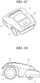
- FIGS. 1C and 1D illustrate an embodiment of the moving robot 10, in a case where the moving robot 10 is implemented as a lawn mower.
- the lawn mower 10 may include a body 50 formed to be moveable and configured to mow lawn.
- the body 50 may mow lawn inside the operation region 1000 while moving within the boundary wire 1200.
- the boundary wire 1200 may be connected to the charging equipment 100 for supplying a current to the boundary wire 1200. That is, the boundary wire 1200 may be connected to the charging equipment 100, and may generate a magnetic field by a current supplied from the charging equipment 100. The body 50 may be charged by being coupled to the charging equipment 100.
- a cutting unit configured to mow lawn may be provided at the body 50 of the lawn mower.
- the cutting unit may have a sharp blade formed to be rotatable.
- a driving unit configured to move the body 50 to a desired direction and to rotate the body 50, is provided at the body 50.
- the driving unit may include a plurality of rotatable wheels, and each of the wheels may be rotatable individually. With such a configuration, the body 50 may be rotatable to a desired direction.
- the driving unit may include at least one main driving wheel 40, and at least one auxiliary wheel 20.
- the body 50 may include two main driving wheels 40, and the two main driving wheels 40 may be installed at a bottom surface of a rear side of the body 50.
- the body 50 may include a sensing unit 30 configured to sense the boundary wire 1200.
- the sensing unit 30 may sense whether the body 50 has reached the boundary wire 1200, whether the body 50 is positioned within a closed surface formed by the boundary wire 1200, whether the body 50 is running along the boundary wire 1200, etc.
- the sensing unit 30 may acquire information about the sensing, based on a magnetic field generated by a current which flows on the boundary wire 1200, and based on a voltage generated by the magnetic field by induction.
- the sensing unit 30 may also sense various information about a moving distance of the body 50, a moving speed of the body 50, etc.
- the body 50 may drive the driving unit 40 based on the information sensed by the sensing unit 30. That is, a controller 20 may control driving of the body 50 based on information measured by the sensing unit 30, thereby driving the driving unit such that the body 50 is positioned within the operation region.
- the body 50 may include the sensing unit 30 configured to sense a voltage induced from the boundary wire 1200, and the controller 20 configured to determine a distance between the body 50 and the boundary wire 1200 based on the voltage sensed by the sensing unit 30.
- the body 50 may include a power receiving unit 60 configured to receive power by contacting the charging equipment 100.
- the power receiving unit 60 may include at least one terminal. More specifically, the terminal may be formed to be moveable up and down, by being coupled to an elastic unit (not shown).
- the power receiving unit 60 may be installed above one of the main driving wheels 40 of the driving unit.
- the power receiving unit 60 may be installed to be exposed toward an upper side of the body 50.
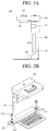
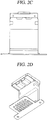
- FIGS. 2A to 2D illustrate an embodiment of the charging equipment for the moving robot according to the present invention.
- the charging equipment 100 for the moving robot may include at least one of a bottom unit 101, a supporting unit 102 and a terminal unit 103.
- the bottom unit 101, the supporting unit 102 and the terminal unit 103 may be formed independently.
- the charging equipment 100 may be formed as the bottom unit 101, the supporting unit 102 and the terminal unit 103 which are formed independently are coupled to each other.
- At least one of the bottom unit 101, the supporting unit 102 and the terminal unit 103 may be coupled to each other by a hinge (not shown).
- at least one of the bottom unit 101, the supporting unit 102 and the terminal unit 103 may be coupled to each other by a coupling part (not shown) formed at each of the bottom unit 101, the supporting unit 102 and the terminal unit 103.
- At least one of the bottom unit 101, the supporting unit 102 and the terminal unit 103 may be formed integrally with each other.
- the bottom unit 101 may be installed on at least part of the operation region of the moving robot. If the moving robot is being charged, the bottom unit 101 may be formed to mount one of the plurality of wheels of the moving robot.
- a direction facing the body 50 of the robot is defined as a front surface or a front side of the supporting unit 102, and an opposite direction to the front surface of the front side is defined as a rear surface or a rear side of the supporting unit 102.
- a normal direction of a ground surface is defined as an upper side of the supporting unit 102, and an opposite direction to the upper side of the supporting unit 102 is defined as a lower side of the supporting unit 102.
- the remaining two directions except for the front side, the rear side, the upper side and the lower side of the supporting unit 102 are defined as side surfaces or lateral sides of the supporting unit 102.
- a front surface, a rear surface, side surfaces, an upper surface and a lower surface of each of the bottom unit 101 and the terminal unit 103 are defined.
- a plurality of holes 111 may be formed at the bottom unit 101.
- the bottom unit 101 may be provided with protrusions 121 between a first part and a second part where the plurality of homes are formed. With such a configuration, damage of lawn may be minimized since the lawn disposed at part of an installation region of the bottom unit 101 grows through the plurality of holes 111.
- the protrusions 121 may increase a grip force between the main driving wheel of the moving robot and the bottom unit 101.
- the plurality of holes 111 may be more formed at the second part of the bottom unit not contacting the wheels of the moving robot, than at the first part of the bottom unit contacting the wheels of the moving robot when the moving robot is being charged.
- the plurality of holes formed at the second part may have a larger size than the plurality of holes formed at the first part.
- the bottom unit 101 may include coupling portions 131 configured to fix the bottom unit 101 to the operation region.
- a coupling hole of a predetermined size may be formed at the coupling portion 131.
- a coupling member 131 a is coupled to the ground surface through the coupling hole of the coupling portion 131, thereby fixing the bottom unit 101 to the ground surface.
- the coupling portions and the coupling holes are formed at two sides of the bottom unit 101.
- the coupling portion 131 may be coupled to the boundary wire 1200.
- the boundary wire 1200 may receive a current through the coupling portions 131.
- the coupling portion 131 may be provided with a current supply terminal (not shown).
- the coupling portion 131 may be also provided with a wire coupling part (not shown) configured to couple the boundary wire 1200 with the coupling portion 131.
- FIG. 2B illustrates an embodiment where the coupling portions are positioned at two side surfaces of the bottom unit.
- the present invention is not limited to this. That is, the coupling portions may be positioned at two side surfaces of the supporting unit 102. In this case, the coupling portions may be connected to the boundary wire installed at an outline of an operation of the moving robot.
- At least one of the bottom unit and the supporting unit may include the coupling portions connected to the boundary wire installed at an outline of an operation of the moving robot.
- the bottom unit may be installed such that its one surface may contact the boundary wire.
- the one surface of the bottom unit, which contacts the boundary wire may be a rear surface of the bottom unit.
- the coupling portions are disposed at two side surfaces of the bottom unit or the supporting unit, the charging equipment for the moving robot (lawn mower) may be more easily aligned with the boundary wire 1200 in a specific direction.
- the supporting unit 102 may be coupled to the bottom unit 101. At least one of the supporting unit 102 and the bottom unit 101 may be provided with a coupling member (not shown) for coupling therebetween.
- the supporting unit 102 may be positioned at a lateral side of the body 50 of the moving robot.
- the supporting unit 102 may be provided with a concaved portion 102a such that the supporting unit 102 may not contact one of the wheels 40 of the moving robot when the moving robot is being charged. That is, the supporting unit 102 may include a first supporting member (concaved portion 102a) formed to have a first thickness, and a second supporting member formed to have a second thickness and configured to support the charging equipment by being coupled to at least one of the bottom unit 101 and the terminal unit 103.
- a sensor 112 may be attached to a side surface of the supporting unit 102. More specifically, the sensor 112 may be an IR sensor.
- the IR sensor 112 may transmit a preset signal to the moving robot, or may receive a preset signal from the moving robot. More specifically, the preset signal may include information about a position of the charging equipment, information indicating whether the charging equipment can execute a charging operation or not.
- a wire cap 122 may be provided on a rear surface of the supporting unit 102.
- the wire cap 122 may cover a coupling member between the boundary wire 1200 and the charging equipment 100, in a case where the charging equipment 100 and the boundary wire 1200 are connected to the same power source.
- An embodiment of the wire cap 122 will be explained in more detail with reference to FIG. 7 .
- the terminal unit 103 may be coupled to the supporting unit 102. More specifically, a coupling angle between the terminal unit 103 and the supporting unit 102 may be changed by an external force.
- One or more terminals 113 may be installed on a lower surface of the terminal unit 103.
- the terminals 113 may be configured to supply power to the moving robot 10, by contacting the power receiving unit 60 of the moving robot 10 (refer to FIGS. 1C and 1D ).
- an elastic member (not shown) may be installed between the terminals 1113 and the terminal unit 103. With such a configuration, a protruded length of the terminals 113 may be changed by an external force.
- the terminals 113 may be formed of an elastic material. That is, the terminals 113 may be bent by an external force, and thus a protruded degree of the terminals 113 may be changed.
- the terminal unit 103 may supply power to the moving robot 10 in a wireless manner.
- the terminal unit 103 may be provided with a wireless power transmitting portion (not shown), and the moving robot 10 may be provided with a wireless power receiving portion (not shown).
- the charging equipment 100 may supply power to the moving robot 10, even in a state where the terminal unit 103 is spaced from an upper surface of the moving robot 10 by a predetermined distance.
- a handgrip 123 may be installed on an upper surface of the terminal unit 103.
- a relative coupling position between the terminal unit 103 and the supporting unit 102 may be changed by an external force applied to the handgrip 123.
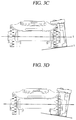
- FIGS. 3A to 3D are views illustrating an embodiment of the charging equipment to which the moving robot according to the present invention has been coupled.
- the bottom unit 101 of the charging equipment 100 may be formed to be mounted to only one of the plurality of wheels 40 of the moving robot 10, in a case where the moving robot 10 is being charged.
- the wheels 40 mounted to the bottom unit 101 may be main driving wheels installed at the body of the moving robot.
- the main driving wheels may be installed at a rear side of the body of the moving robot.
- the bottom unit 101 may be formed to have a quadrangular shape.
- a length of a side surface of the bottom unit 101 may be greater than a width of the wheel of the moving robot 10.
- a length of a front surface or a rear surface of the bottom unit 101 may be formed to be greater than a diameter of the wheel of the moving robot 10.
- the bottom unit 101 of the charging equipment 100 according to the present invention is not limited to this.
- the length of the front surface or the rear surface of the bottom unit 101 may be formed to be equal to or greater than a contact area between the wheel of the moving robot 10 and a ground surface, in a case where the wheel of the moving robot 10 contacts the ground surface. In this case, since an area of the bottom unit 101 can be minimized, operation efficiency of the moving robot 10 may be enhanced, and damage of lawn may be minimized.
- the terminals 113 of the terminal unit 103 of the charging equipment 100 may maintain a contacted state with the power receiving unit 60 of the moving robot 10.
- the charging equipment 100 may supply power to the moving robot 10 through the terminal unit 103.
- the preset range may be 0° ⁇ 10°.
- a coupling angle between the terminal unit 103 and the supporting unit 102 may be changed such that the contacted state between the terminals 113 and the power receiving unit 60 may be maintained.
- a relative coupling position between the terminal unit 103 and the terminals 113 provided on a lower surface of the terminal unit 103 may be changed.
- the terminals 113 may be formed of a magnetic substance, and may move in a coupled state to the lower surface of the terminal unit 103, so as to contact the power receiving unit 60 formed of a metallic material.
- an elastic member (not shown) may be provided between the terminals 113 and the terminal unit 103, and the elastic member may change a protruded degree of the terminals 113.
- the charging equipment 100 of the present invention may efficiently supply power to the moving robot 10, even if the operation region 1000 does not have a flat surface. That is, the charging equipment 100 of the present invention may efficiently supply power to the moving robot 10, even when the moving robot 10 has been mounted to the charging equipment 100 with various postures.
- FIGS. 4A and 4B are views illustrating an embodiment of the terminal unit of the charging equipment for the moving robot according to the present invention.
- a coupling angle between the terminal unit 103 and the supporting unit 102 of the charging equipment 100 may be changed by an external force. More specifically, in a state where a first external force has been applied to the terminal unit 103 in a direction parallel to a ground surface, if a second external force is applied to the terminal unit 103 in a direction perpendicular to the ground surface, the coupling angle between the terminal unit 103 and the supporting unit 102 may be changed.
- FIG. 4B illustrates an embodiment of a coupling part 400 between the terminal unit 103 and the supporting unit 102.
- the terminal unit 103 and the supporting unit 102 may be coupled to each other by a hinge 401. And the terminal unit 103 and the supporting unit 102 may be coupled to two ends of a spring 402. With such a configuration, if an external force applied to the terminal unit 103 disappears, the coupling angle between the terminal unit 103 and the supporting unit 102 may return to an initial value. For instance, the initial value may be 90°.
- FIG. 4B illustrates that the terminal unit 103 and the supporting unit 102 are coupled to two ends of the spring 402.
- the present invention is not limited to this.
- FIGS. 5A, 5B , 6A and 6B are views illustrating an embodiment of the supporting unit 102 of the charging equipment 100.
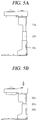
- the supporting unit 102 may include a plurality of rods 102a, 102b, 102c, and the plurality of rods 102a, 102b, 102c may be formed to have different diameters. And the plurality of rods 102a, 102b, 102c may be sequentially coupled to each other.
- a length of the supporting unit 102 may be changed.
- each rod may be provided with a hole member (not shown) and a pin member (not shown) for fixing a coupled state between the rods.
- the coupled state between the hole member of the first rod 102a and the pin member of the second rod 102b may be changed. That is, if the coupled state between the hole member of the first rod 102a and the pin member of the second rod 102b is released, the first rod 102a may be inserted into the second rod 102b more deeply, or may be protruded out from the second rod 102b.
- the charging equipment 100 may further include a controller (not shown).
- the controller may control the coupled state among the plurality of rods to be changed, if it is determined that no power is being supplied to the moving robot 10. More specifically, if it is determined that no power is being supplied to the moving robot 10, the controller may change the coupled state among the plurality of rods such that a length of the supporting unit may be reduced.
- the controller may determine whether the moving robot 10 is approaching the charging equipment 100 or not, based on information received from the sensor 112. In this case, the controller may change the coupled state among the plurality of rods such that the length of the supporting unit may be increased, for power supply to the moving robot 10.
- a first coupled state maintaining member (not shown) and a second coupled state maintaining member (not shown), configured to maintain a coupled state between the first and second rods may be provided at the first and second rods 102a, 102b, respectively.
- the first and second coupled state maintaining members may be formed against an external force applied to the supporting unit, such that a coupled state between the first and second rods may be maintained.
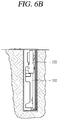
- the bottom unit 101 of the charging equipment 100 may include a first bottom member 101 a installed on a ground surface, and a second bottom member 101b buried below the ground surface. More specifically, the second bottom member 101b may be formed to have a width greater than a width of the supporting unit.
- the supporting unit 102 coupled to the bottom unit 101, and the terminal unit 103 coupled to the supporting unit 102 may be inserted into the second bottom member 101b, as a coupled state among the bottom unit, the supporting unit and the terminal unit is changed.
- the coupled state among the bottom unit, the supporting unit and the terminal unit may be changed by a user's external force, or under control of the controller of the charging equipment 100.
- the bottom unit 101 may be provided with a sensor.
- an installation volume of the charging equipment 100 may be minimized. This may enhance a user's convenience.
- FIG. 7 is a view illustrating an embodiment of a rear surface of the supporting unit 102 of the charging equipment 100 according to the present invention.
- wire caps 122a, 122b may be provided on right and left sides of a rear surface of the supporting unit 102.
- the wire cap 122 may cover a coupling member between the boundary wire 1200 and the charging equipment 100, in a case where the charging equipment 100 and the boundary wire 1200 are connected to the same power source.
- the wire cap 122 may cover a coupling member between a power supply wire (not shown) connected to the boundary wire 1200 and the charging equipment 100.
- the present invention may have the following advantages.
- operation efficiency of the lawn mower may be enhanced by the charging equipment which does not hinder a driving of the lawn mower.
Landscapes
- Engineering & Computer Science (AREA)
- Physics & Mathematics (AREA)
- Environmental Sciences (AREA)
- Life Sciences & Earth Sciences (AREA)
- General Physics & Mathematics (AREA)
- Aviation & Aerospace Engineering (AREA)
- Radar, Positioning & Navigation (AREA)
- Remote Sensing (AREA)
- Automation & Control Theory (AREA)
- Electromagnetism (AREA)
- Power Engineering (AREA)
- Harvester Elements (AREA)
- Electric Propulsion And Braking For Vehicles (AREA)
- Charge And Discharge Circuits For Batteries Or The Like (AREA)
Abstract
Description
- The present invention relates to a charging equipment for a moving robot and a controlling method thereof, and more particularly, to a charging equipment for a lawn mower which moves inside a boundary wire, and a controlling method thereof.
- A lawn mower is an apparatus for trimming lawn planted in a yard of a house, a playground, etc. The lawn mower may be divided into a home lawn mower used at home, and a tractor lawn mower used in a wide playground or a wide farm.
- The home lawn mower is categorized into a walk behind type moved by a man positioned at a rear side of the lawn mower, and a handheld type directly carried by a user's hands.
- However, there is a user's difficulty in directly operating the two types of lawn mowers.
- Especially, since modern people generally tend to hire a person to trim lawn due to a busy daily life and a difficult trimming operation, high costs are generated.
- Thus, an automatic robot type of lawn mower, to prevent high costs and to solve a user's difficulty, is being developed. Research on control of such an automatic robot type of lawn mower is ongoing actively.
- Further, in order to realize automatic power supply to the automatic robot type of lawn mower, a charging equipment for the lawn mower is being developed. Since charging performance of the charging equipment is related to a driving control of the automatic robot, research on the charging equipment, as well as research on control of moving performance of the automatic robot, is ongoing.
- Therefore, an aspect of the detailed description is to provide a charging equipment for a moving robot, capable of smoothly supplying power to the moving robot, and capable of protecting lawn positioned within an operation region of the moving robot, and a controlling method thereof.
- Another aspect of the detailed description is to provide a charging equipment for a moving robot, capable of minimizing a sharing region between an installation region of the charging equipment and an operation region of the moving robot, and a controlling method thereof.
- Another aspect of the detailed description is to provide a charging equipment for a moving robot, which is installed outside a closed curve defined by a boundary wire installed at an outer periphery of an operation region, and a controlling method thereof.
- To achieve these and other advantages and in accordance with the purpose of this specification, as embodied and broadly described herein, there is provided a charging equipment for a moving robot, including: a bottom unit installed at part of an operation region of the moving robot; a supporting unit coupled to the bottom unit, and positioned on a lateral side of a body of the moving robot when the robot is being charged; and a terminal unit coupled to the supporting unit, and positioned on an upper side of the body of the moving robot when the robot is being charged, wherein the bottom unit is formed to mount one of a plurality of wheels of the moving robot when the moving robot is being charged.
- In an embodiment of the present invention, the wheel mounted to the bottom unit may be one of main driving wheels installed at the body of the moving robot.
- In an embodiment of the present invention, the bottom unit may be provided with a plurality of holes.
- In an embodiment of the present invention, a coupling angle between the terminal unit and the supporting unit may be changed by an external force.
- In an embodiment of the present invention, if the moving robot is being charged, the supporting unit may be provided with a concaved portion facing the body of the moving robot.
- In an embodiment of the present invention, an IR sensor may be attached to a side surface of the supporting unit, and the attached IR sensor may transmit a preset signal to the moving robot.
- In an embodiment of the present invention, the supporting unit may include a plurality of rods, and the plurality of rods may be formed to have different diameters, and may be sequentially coupled to each other. As the coupled state among the plurality of rods is changed, a length of the supporting unit may be changed.
- In an embodiment of the present invention, the bottom unit may include a first bottom member installed on a ground surface, and a second bottom member buried below the ground surface. At least one of the bottom unit, the supporting unit, and the terminal unit may be inserted into the second bottom member, as the coupled state among the bottom unit, the supporting unit and the terminal unit is changed.
- In an embodiment of the present invention, at least one of the bottom unit, the supporting unit, and the terminal unit may include coupling portions connected to a boundary wire installed at an outline of the operation region.
- In an embodiment of the present invention, the bottom unit may be installed such that its one surface contacts the boundary wire.
- The present invention may have the following advantages.
- Firstly, when the charging equipment for supplying power to the moving robot (lawn mower) is installed, damage of lawn positioned within an operation region of the lawn mower may be minimized.
- Secondly, operation efficiency of the lawn mower may be enhanced by the charging equipment which does not hinder a driving of the lawn mower.
- Further, as an installation region and a size of the charging equipment are reduced, a user's convenience in using the lawn mower may be enhanced.
- Further scope of applicability of the present application will become more apparent from the detailed description given hereinafter. However, it should be understood that the detailed description and specific examples, while indicating preferred embodiments of the invention, are given by way of illustration only, since various changes and modifications within the spirit and scope of the invention will become apparent to those skilled in the art from the detailed description.
- The accompanying drawings, which are included to provide a further understanding of the invention and are incorporated in and constitute a part of this specification, illustrate exemplary embodiments and together with the description serve to explain the principles of the invention.
- In the drawings:
-
FIGS. 1A and 1B are conceptual views illustrating an embodiment where a charging equipment for a moving robot according to the present invention is installed at an operation region for a moving robot; -
FIGS. 1C and 1D are conceptual views illustrating an embodiment of a moving robot; -
FIGS. 2A to 2D are perspective views illustrating a charging equipment for a moving robot according to an embodiment of the present invention, at various angles; -
FIGS. 3A to 3D are views illustrating an embodiment of a charging equipment to which a moving robot according to the present invention has been coupled; -
FIGS. 4A and 4B are views illustrating an embodiment of a terminal unit of a charging equipment for a moving robot according to the present invention; -
FIGS. 5A, 5B ,6A and6B are views illustrating an embodiment of a supporting unit of a charging equipment for a moving robot according to the present invention; and -
FIG. 7 is a view illustrating an embodiment of a rear surface of the supporting unit of a charging equipment for a moving robot according to the present invention. - Description will now be given in detail of preferred configurations of a charging equipment for a moving robot, and a controlling method thereof according to the present invention, with reference to the accompanying drawings.
- For the sake of brief description with reference to the drawings, the same or equivalent components may be provided with the same or similar reference numbers, and description thereof will not be repeated. A singular representation may include a plural representation unless it represents a definitely different meaning from the context.
-
FIGS. 1A and 1B are conceptual views illustrating an embodiment where acharging equipment 100 for a movingrobot 10 according to the present invention is installed at anoperation region 1000 for the movingrobot 10. - Referring to
FIG. 1A , the movingrobot 10 may autonomously move within a predetermined region. Further, the movingrobot 10 may execute a specific function while moving. - More specifically, the moving
robot 10 may be a lawn mower. In this case, the specific function may be a function to mow (trim) lawn within theoperation region 1000. - The
operation region 1000 may be defined by aboundary wire 1200 formed as a closed curve. More specifically, theboundary wire 1200 may be installed at an arbitrary region. And the movingrobot 10 may move within a region defined by the closed curve of theboundary wire 1200. - Referring to
FIG. 1B , theboundary wire 1200 may be installed inside theoperation region 1000. More specifically, theboundary wire 1200 may be installed at a boundary between theoperation region 1000 of the movingrobot 10 and anexternal region 1100, or may be spaced from theexternal region 1100 with a predetermined interval (d). In this case, the predetermined interval (d) for installation of theboundary wire 1200 may be variable. Thus, a user may install theboundary wire 1200 along an outer periphery of theoperation region 1000, and may install theboundary wire 1200 more easily because an installation interval of theboundary wire 1200 from the outer periphery or theexternal region 1100 needs not be considered. - As shown in
FIG. 1B , thecharging equipment 100 for the movingrobot 10 may be installed so as to be connected to theboundary wire 1200. Although not shown, thecharging equipment 100 may be also installed at part of theoperation region 1000 including an installation region of theboundary wire 1200. Although not shown inFIG. 1B , thecharging equipment 100 may be installed at part of theoperation region 1000, or at part of theexternal region 1100. -
FIGS. 1C and 1D illustrate an embodiment of the movingrobot 10, in a case where the movingrobot 10 is implemented as a lawn mower. - Referring to
FIGS. 1C and 1D , thelawn mower 10 may include abody 50 formed to be moveable and configured to mow lawn. Thebody 50 may mow lawn inside theoperation region 1000 while moving within theboundary wire 1200. - The
boundary wire 1200 may be connected to thecharging equipment 100 for supplying a current to theboundary wire 1200. That is, theboundary wire 1200 may be connected to thecharging equipment 100, and may generate a magnetic field by a current supplied from thecharging equipment 100. Thebody 50 may be charged by being coupled to thecharging equipment 100. - A cutting unit (not shown) configured to mow lawn may be provided at the
body 50 of the lawn mower. The cutting unit may have a sharp blade formed to be rotatable. - A driving unit, configured to move the
body 50 to a desired direction and to rotate thebody 50, is provided at thebody 50. The driving unit may include a plurality of rotatable wheels, and each of the wheels may be rotatable individually. With such a configuration, thebody 50 may be rotatable to a desired direction. More specifically, the driving unit may include at least onemain driving wheel 40, and at least oneauxiliary wheel 20. For instance, thebody 50 may include twomain driving wheels 40, and the twomain driving wheels 40 may be installed at a bottom surface of a rear side of thebody 50. - The
body 50 may include a sensing unit 30 configured to sense theboundary wire 1200. The sensing unit 30 may sense whether thebody 50 has reached theboundary wire 1200, whether thebody 50 is positioned within a closed surface formed by theboundary wire 1200, whether thebody 50 is running along theboundary wire 1200, etc. In this case, the sensing unit 30 may acquire information about the sensing, based on a magnetic field generated by a current which flows on theboundary wire 1200, and based on a voltage generated by the magnetic field by induction. - The sensing unit 30 may also sense various information about a moving distance of the
body 50, a moving speed of thebody 50, etc. - The
body 50 may drive the drivingunit 40 based on the information sensed by the sensing unit 30. That is, acontroller 20 may control driving of thebody 50 based on information measured by the sensing unit 30, thereby driving the driving unit such that thebody 50 is positioned within the operation region. - The
body 50 may include the sensing unit 30 configured to sense a voltage induced from theboundary wire 1200, and thecontroller 20 configured to determine a distance between thebody 50 and theboundary wire 1200 based on the voltage sensed by the sensing unit 30. - The
body 50 may include apower receiving unit 60 configured to receive power by contacting thecharging equipment 100. Thepower receiving unit 60 may include at least one terminal. More specifically, the terminal may be formed to be moveable up and down, by being coupled to an elastic unit (not shown). Thepower receiving unit 60 may be installed above one of themain driving wheels 40 of the driving unit. Thepower receiving unit 60 may be installed to be exposed toward an upper side of thebody 50. -
FIGS. 2A to 2D illustrate an embodiment of the charging equipment for the moving robot according to the present invention. - Referring to
FIG. 2A , thecharging equipment 100 for the moving robot according to the present invention may include at least one of abottom unit 101, a supportingunit 102 and aterminal unit 103. - As shown in
FIG. 2A , thebottom unit 101, the supportingunit 102 and theterminal unit 103 may be formed independently. Thecharging equipment 100 may be formed as thebottom unit 101, the supportingunit 102 and theterminal unit 103 which are formed independently are coupled to each other. At least one of thebottom unit 101, the supportingunit 102 and theterminal unit 103 may be coupled to each other by a hinge (not shown). Alternatively, at least one of thebottom unit 101, the supportingunit 102 and theterminal unit 103 may be coupled to each other by a coupling part (not shown) formed at each of thebottom unit 101, the supportingunit 102 and theterminal unit 103. - Although not shown, at least one of the
bottom unit 101, the supportingunit 102 and theterminal unit 103 may be formed integrally with each other. - More specifically, the
bottom unit 101 may be installed on at least part of the operation region of the moving robot. If the moving robot is being charged, thebottom unit 101 may be formed to mount one of the plurality of wheels of the moving robot. - In the following descriptions, under an assumption that the moving robot is being charged, a direction facing the
body 50 of the robot is defined as a front surface or a front side of the supportingunit 102, and an opposite direction to the front surface of the front side is defined as a rear surface or a rear side of the supportingunit 102. A normal direction of a ground surface is defined as an upper side of the supportingunit 102, and an opposite direction to the upper side of the supportingunit 102 is defined as a lower side of the supportingunit 102. And the remaining two directions except for the front side, the rear side, the upper side and the lower side of the supportingunit 102, are defined as side surfaces or lateral sides of the supportingunit 102. - In the same manner, a front surface, a rear surface, side surfaces, an upper surface and a lower surface of each of the
bottom unit 101 and theterminal unit 103 are defined. - As shown in
FIG. 2B , a plurality ofholes 111 may be formed at thebottom unit 101. Thebottom unit 101 may be provided withprotrusions 121 between a first part and a second part where the plurality of homes are formed. With such a configuration, damage of lawn may be minimized since the lawn disposed at part of an installation region of thebottom unit 101 grows through the plurality ofholes 111. Theprotrusions 121 may increase a grip force between the main driving wheel of the moving robot and thebottom unit 101. - Although not shown, the plurality of
holes 111 may be more formed at the second part of the bottom unit not contacting the wheels of the moving robot, than at the first part of the bottom unit contacting the wheels of the moving robot when the moving robot is being charged. As another example, the plurality of holes formed at the second part may have a larger size than the plurality of holes formed at the first part. - Referring to
FIG. 2B , thebottom unit 101 may includecoupling portions 131 configured to fix thebottom unit 101 to the operation region. A coupling hole of a predetermined size may be formed at thecoupling portion 131. Acoupling member 131 a is coupled to the ground surface through the coupling hole of thecoupling portion 131, thereby fixing thebottom unit 101 to the ground surface. In the drawings, the coupling portions and the coupling holes are formed at two sides of thebottom unit 101. - Although not shown in
FIG. 2B , thecoupling portion 131 may be coupled to theboundary wire 1200. In a case where thecharging equipment 100 and theboundary wire 1200 receive power from the same power source, theboundary wire 1200 may receive a current through thecoupling portions 131. - In this case, the
coupling portion 131 may be provided with a current supply terminal (not shown). Thecoupling portion 131 may be also provided with a wire coupling part (not shown) configured to couple theboundary wire 1200 with thecoupling portion 131. -
FIG. 2B illustrates an embodiment where the coupling portions are positioned at two side surfaces of the bottom unit. However, the present invention is not limited to this. That is, the coupling portions may be positioned at two side surfaces of the supportingunit 102. In this case, the coupling portions may be connected to the boundary wire installed at an outline of an operation of the moving robot. - More specifically, at least one of the bottom unit and the supporting unit may include the coupling portions connected to the boundary wire installed at an outline of an operation of the moving robot.
- The bottom unit may be installed such that its one surface may contact the boundary wire. For instance, the one surface of the bottom unit, which contacts the boundary wire, may be a rear surface of the bottom unit.
- Since the coupling portions are disposed at two side surfaces of the bottom unit or the supporting unit, the charging equipment for the moving robot (lawn mower) may be more easily aligned with the
boundary wire 1200 in a specific direction. - Referring to
FIGS. 2A to 2D , the supportingunit 102 may be coupled to thebottom unit 101. At least one of the supportingunit 102 and thebottom unit 101 may be provided with a coupling member (not shown) for coupling therebetween. - If the moving robot is being charged, the supporting
unit 102 may be positioned at a lateral side of thebody 50 of the moving robot. The supportingunit 102 may be provided with aconcaved portion 102a such that the supportingunit 102 may not contact one of thewheels 40 of the moving robot when the moving robot is being charged. That is, the supportingunit 102 may include a first supporting member (concaved portion 102a) formed to have a first thickness, and a second supporting member formed to have a second thickness and configured to support the charging equipment by being coupled to at least one of thebottom unit 101 and theterminal unit 103. - A
sensor 112 may be attached to a side surface of the supportingunit 102. More specifically, thesensor 112 may be an IR sensor. - The
IR sensor 112 may transmit a preset signal to the moving robot, or may receive a preset signal from the moving robot. More specifically, the preset signal may include information about a position of the charging equipment, information indicating whether the charging equipment can execute a charging operation or not. - A
wire cap 122 may be provided on a rear surface of the supportingunit 102. Thewire cap 122 may cover a coupling member between theboundary wire 1200 and thecharging equipment 100, in a case where thecharging equipment 100 and theboundary wire 1200 are connected to the same power source. An embodiment of thewire cap 122 will be explained in more detail with reference toFIG. 7 . - Referring to
FIGS. 2A to 2D , theterminal unit 103 may be coupled to the supportingunit 102. More specifically, a coupling angle between theterminal unit 103 and the supportingunit 102 may be changed by an external force. - One or
more terminals 113 may be installed on a lower surface of theterminal unit 103. Theterminals 113 may be configured to supply power to the movingrobot 10, by contacting thepower receiving unit 60 of the moving robot 10 (refer toFIGS. 1C and 1D ). - As an example, an elastic member (not shown) may be installed between the terminals 1113 and the
terminal unit 103. With such a configuration, a protruded length of theterminals 113 may be changed by an external force. - As another example, the
terminals 113 may be formed of an elastic material. That is, theterminals 113 may be bent by an external force, and thus a protruded degree of theterminals 113 may be changed. - Although not shown in
FIGS. 2A to 2D , theterminal unit 103 may supply power to the movingrobot 10 in a wireless manner. In this case, theterminal unit 103 may be provided with a wireless power transmitting portion (not shown), and the movingrobot 10 may be provided with a wireless power receiving portion (not shown). With such a configuration, thecharging equipment 100 may supply power to the movingrobot 10, even in a state where theterminal unit 103 is spaced from an upper surface of the movingrobot 10 by a predetermined distance. - As shown in
FIGS. 2A to 2D , ahandgrip 123 may be installed on an upper surface of theterminal unit 103. A relative coupling position between theterminal unit 103 and the supportingunit 102 may be changed by an external force applied to thehandgrip 123. -
FIGS. 3A to 3D are views illustrating an embodiment of the charging equipment to which the moving robot according to the present invention has been coupled. - As shown in
FIGS. 3A and 3B , thebottom unit 101 of thecharging equipment 100 may be formed to be mounted to only one of the plurality ofwheels 40 of the movingrobot 10, in a case where the movingrobot 10 is being charged. - More specifically, the
wheels 40 mounted to thebottom unit 101 may be main driving wheels installed at the body of the moving robot. As another example, the main driving wheels may be installed at a rear side of the body of the moving robot. - As shown in
FIG. 3A , thebottom unit 101 may be formed to have a quadrangular shape. In this case, a length of a side surface of thebottom unit 101 may be greater than a width of the wheel of the movingrobot 10. - Referring to
FIG. 3A , a length of a front surface or a rear surface of thebottom unit 101 may be formed to be greater than a diameter of the wheel of the movingrobot 10. However, thebottom unit 101 of thecharging equipment 100 according to the present invention is not limited to this. - As another example, the length of the front surface or the rear surface of the
bottom unit 101 may be formed to be equal to or greater than a contact area between the wheel of the movingrobot 10 and a ground surface, in a case where the wheel of the movingrobot 10 contacts the ground surface. In this case, since an area of thebottom unit 101 can be minimized, operation efficiency of the movingrobot 10 may be enhanced, and damage of lawn may be minimized. - Referring to
FIGS. 3C and 3D , if an absolute value of an angle (α) formed between a rotation shaft of thewheel 40 of the movingrobot 10 and thebottom unit 101 is within a preset range, theterminals 113 of theterminal unit 103 of thecharging equipment 100 may maintain a contacted state with thepower receiving unit 60 of the movingrobot 10. - That is, if the angle (α) formed between the rotation shaft of the
wheel 40 of the movingrobot 10 and thebottom unit 101 is within the preset range, thecharging equipment 100 may supply power to the movingrobot 10 through theterminal unit 103. For instance, the preset range may be 0°~ 10°. - Although not shown in
FIGS. 3C and 3D , the absolute value of the angle (α) is within the preset range, a coupling angle between theterminal unit 103 and the supportingunit 102 may be changed such that the contacted state between theterminals 113 and thepower receiving unit 60 may be maintained. - In another embodiment, a relative coupling position between the
terminal unit 103 and theterminals 113 provided on a lower surface of theterminal unit 103 may be changed. In this case, theterminals 113 may be formed of a magnetic substance, and may move in a coupled state to the lower surface of theterminal unit 103, so as to contact thepower receiving unit 60 formed of a metallic material. - In another embodiment, an elastic member (not shown) may be provided between the
terminals 113 and theterminal unit 103, and the elastic member may change a protruded degree of theterminals 113. With such a configuration, the contacted state between theterminals 113 and thepower receiving unit 60 may be maintained, even if an entering posture of the movingrobot 10 for charging is changed. - Accordingly, the
charging equipment 100 of the present invention may efficiently supply power to the movingrobot 10, even if theoperation region 1000 does not have a flat surface. That is, thecharging equipment 100 of the present invention may efficiently supply power to the movingrobot 10, even when the movingrobot 10 has been mounted to thecharging equipment 100 with various postures. -
FIGS. 4A and 4B are views illustrating an embodiment of the terminal unit of the charging equipment for the moving robot according to the present invention. - Referring to
FIG. 4A , a coupling angle between theterminal unit 103 and the supportingunit 102 of thecharging equipment 100 may be changed by an external force. More specifically, in a state where a first external force has been applied to theterminal unit 103 in a direction parallel to a ground surface, if a second external force is applied to theterminal unit 103 in a direction perpendicular to the ground surface, the coupling angle between theterminal unit 103 and the supportingunit 102 may be changed. -
FIG. 4B illustrates an embodiment of acoupling part 400 between theterminal unit 103 and the supportingunit 102. - As shown in
FIG. 4B , theterminal unit 103 and the supportingunit 102 may be coupled to each other by ahinge 401. And theterminal unit 103 and the supportingunit 102 may be coupled to two ends of aspring 402. With such a configuration, if an external force applied to theterminal unit 103 disappears, the coupling angle between theterminal unit 103 and the supportingunit 102 may return to an initial value. For instance, the initial value may be 90°. -
FIG. 4B illustrates that theterminal unit 103 and the supportingunit 102 are coupled to two ends of thespring 402. However, the present invention is not limited to this. -
FIGS. 5A, 5B ,6A and6B are views illustrating an embodiment of the supportingunit 102 of thecharging equipment 100. - Referring to
FIG. 5A , the supportingunit 102 may include a plurality ofrods rods rods - As shown in
FIG. 5B , as the coupled state among the plurality of rods is changed, a length of the supportingunit 102 may be changed. - For instance, each rod may be provided with a hole member (not shown) and a pin member (not shown) for fixing a coupled state between the rods. Once the hole member of the
first rod 102a is coupled to the pin member of thesecond rod 102b, the coupled state between the first and second rods may be maintained. - In another embodiment, if the coupled state between the hole member of the
first rod 102a and the pin member of thesecond rod 102b is released, the coupled state between the first and second rods may be changed. That is, if the coupled state between the hole member of thefirst rod 102a and the pin member of thesecond rod 102b is released, thefirst rod 102a may be inserted into thesecond rod 102b more deeply, or may be protruded out from thesecond rod 102b. - In another embodiment, the
charging equipment 100 may further include a controller (not shown). The controller may control the coupled state among the plurality of rods to be changed, if it is determined that no power is being supplied to the movingrobot 10. More specifically, if it is determined that no power is being supplied to the movingrobot 10, the controller may change the coupled state among the plurality of rods such that a length of the supporting unit may be reduced. - In another embodiment, the controller may determine whether the moving
robot 10 is approaching thecharging equipment 100 or not, based on information received from thesensor 112. In this case, the controller may change the coupled state among the plurality of rods such that the length of the supporting unit may be increased, for power supply to the movingrobot 10. - Although not shown in
FIGS. 5A and 5B , a first coupled state maintaining member (not shown) and a second coupled state maintaining member (not shown), configured to maintain a coupled state between the first and second rods, may be provided at the first andsecond rods - Referring to
FIG. 6A , thebottom unit 101 of thecharging equipment 100 according to the present invention may include afirst bottom member 101 a installed on a ground surface, and asecond bottom member 101b buried below the ground surface. More specifically, thesecond bottom member 101b may be formed to have a width greater than a width of the supporting unit. - Referring to
FIG. 6B , the supportingunit 102 coupled to thebottom unit 101, and theterminal unit 103 coupled to the supportingunit 102 may be inserted into thesecond bottom member 101b, as a coupled state among the bottom unit, the supporting unit and the terminal unit is changed. - For instance, the coupled state among the bottom unit, the supporting unit and the terminal unit may be changed by a user's external force, or under control of the controller of the
charging equipment 100. As another example, thebottom unit 101 may be provided with a sensor. - When the
charging equipment 100 is not supplying power to the movingrobot 10, an installation volume of thecharging equipment 100 may be minimized. This may enhance a user's convenience. -
FIG. 7 is a view illustrating an embodiment of a rear surface of the supportingunit 102 of thecharging equipment 100 according to the present invention. - As shown in
FIG. 7 ,wire caps unit 102. - In an embodiment, the
wire cap 122 may cover a coupling member between theboundary wire 1200 and thecharging equipment 100, in a case where thecharging equipment 100 and theboundary wire 1200 are connected to the same power source. - In another embodiment, the
wire cap 122 may cover a coupling member between a power supply wire (not shown) connected to theboundary wire 1200 and thecharging equipment 100. - The present invention may have the following advantages.
- Firstly, when the charging equipment for supplying power to the moving robot (lawn mower) is installed, damage of lawn positioned within an operation region of the lawn mower may be minimized.
- Secondly, operation efficiency of the lawn mower may be enhanced by the charging equipment which does not hinder a driving of the lawn mower.
- Further, as an installation region and a size of the charging equipment are reduced, a user's convenience in using the lawn mower may be enhanced.
- As the present features may be embodied in several forms without departing from the characteristics thereof, it should also be understood that the above-described embodiments are not limited by any of the details of the foregoing description, unless otherwise specified, but rather should be construed broadly within its scope as defined in the appended claims, and therefore all changes and modifications that fall within the metes and bounds of the claims, or equivalents of such metes and bounds are therefore intended to be embraced by the appended claims.
Claims (12)
- A charging equipment for a moving robot, comprising:a bottom unit (101) installed at part of an operation region (1000) of the moving robot (10);a supporting unit (102) coupled to the bottom unit (101), and positioned on a lateral side of a body (50) of the moving robot (10) when the robot (10) is being charged; anda terminal unit (103) coupled to the supporting unit (102), and positioned on an upper side of the body (50) of the moving robot (10) when the robot (10) is being charged,wherein the bottom unit (101) is formed to mount one of a plurality of wheels (40) of the moving robot (10) when the moving robot (10) is being charged.
- The charging equipment for a moving robot of claim 1, wherein the wheel (40) mounted to the bottom unit (101) is one of main driving wheels installed at the body (50) of the moving robot (10).
- The charging equipment for a moving robot of claim 1 or 2, wherein the bottom unit (101) is provided with a plurality of holes (111).
- The charging equipment for a moving robot of claim 3, wherein the bottom unit (101) includes protrusions (121) formed between the plurality of holes (111).
- The charging equipment for a moving robot of any one of the preceding claims, wherein a coupling angle between the terminal unit (103) and the supporting unit (102) is changed by an external force.
- The charging equipment for a moving robot of any one of the preceding claims, wherein if the moving robot (10) is being charged, the supporting unit (102) is provided with a concaved portion facing the body (50) of the moving robot (10).
- The charging equipment for a moving robot of any one of the preceding claims, wherein an IR sensor (112) is attached to a side surface of the supporting unit (102), and
wherein the attached IR sensor (112) transmits a preset signal to the moving robot (10). - The charging equipment for a moving robot of claim 7, wherein the preset signal transmitted from the IR sensor (112) includes information about a position of the charging equipment, information indicating whether a charging operation is executable or not.
- The charging equipment for a moving robot of any one of the preceding claims, wherein the supporting unit (102) includes a plurality of rods (102a-c),
wherein the plurality of rods (102a-c) are formed to have different diameters, and are sequentially coupled to each other, and
wherein as the coupled state among the plurality of rods (102a-c) is changed, a length of the supporting unit (102) is changed. - The charging equipment for a moving robot of any one of the preceding claims, wherein the bottom unit (101) includes a first bottom member (101a) installed on a ground surface, and a second bottom member (101b) buried below the ground surface, and
wherein at least one of the bottom unit (101), the supporting unit (102), and the terminal unit (103) is inserted into the second bottom member (101b), as the coupled state among the bottom unit (101), the supporting unit (102) and the terminal unit (103) is changed. - The charging equipment for a moving robot of any one of the preceding claims, wherein at least one of the bottom unit (101), the supporting unit (102), and the terminal unit (103) includes coupling portions connected to a boundary wire (1200) installed at an outline of the operation region (1000).
- The charging equipment for a moving robot of claim 11, wherein the bottom unit (101) is installed such that its one surface contacts the boundary wire (1200).
Applications Claiming Priority (1)
| Application Number | Priority Date | Filing Date | Title |
|---|---|---|---|
| KR1020150036111A KR102398329B1 (en) | 2015-03-16 | 2015-03-16 | Charging equipment for moving robot and controlling method thereof |
Publications (2)
| Publication Number | Publication Date |
|---|---|
| EP3069593A1 true EP3069593A1 (en) | 2016-09-21 |
| EP3069593B1 EP3069593B1 (en) | 2019-11-20 |
Family
ID=55532207
Family Applications (1)
| Application Number | Title | Priority Date | Filing Date |
|---|---|---|---|
| EP16160413.7A Active EP3069593B1 (en) | 2015-03-16 | 2016-03-15 | Charging equipment for moving robot |
Country Status (2)
| Country | Link |
|---|---|
| EP (1) | EP3069593B1 (en) |
| KR (1) | KR102398329B1 (en) |
Cited By (10)
| Publication number | Priority date | Publication date | Assignee | Title |
|---|---|---|---|---|
| WO2018054255A1 (en) * | 2016-09-23 | 2018-03-29 | 苏州宝时得电动工具有限公司 | Automatic working system, charging station and method for intelligent lawn mower to return to charging station |
| EP3178304A4 (en) * | 2014-08-07 | 2018-04-04 | Positec Power Tools (Suzhou) Co., Ltd | Wireless charging station, automatic mower and automatic mowing system |
| EP3412133A1 (en) * | 2017-06-09 | 2018-12-12 | Andreas Stihl AG & Co. KG | Floor processing system with multiple charging stations |
| US10681864B2 (en) | 2017-06-09 | 2020-06-16 | Andreas Stihl Ag & Co. Kg | Charging station with a data connection for a ground working system |
| US10820493B2 (en) | 2017-06-09 | 2020-11-03 | Andreas Stihl Ag & Co. Kg | Ground working system with signal adaptation |
| EP3547817A4 (en) * | 2016-11-29 | 2020-12-09 | Briggs & Stratton Corporation | ROBOTIC LAWN MOWER WITH DETACHABLE RECHARGEABLE BATTERY MODULE |
| US10986775B2 (en) | 2017-06-09 | 2021-04-27 | Andreas Stihl Ag & Co. Kg | Ground working system with an endless boundary wire |
| CN112970412A (en) * | 2016-05-20 | 2021-06-18 | 苏州宝时得电动工具有限公司 | Charging station, intelligent mower and automatic working system |
| US11064652B2 (en) | 2017-06-09 | 2021-07-20 | Andreas Stihl Ag & Co. Kg | Ground working system with at least one intensive zone |
| US11172609B2 (en) | 2016-06-30 | 2021-11-16 | Tti (Macao Commercial Offshore) Limited | Autonomous lawn mower and a system for navigating thereof |
Families Citing this family (2)
| Publication number | Priority date | Publication date | Assignee | Title |
|---|---|---|---|---|
| KR20190109609A (en) * | 2018-02-23 | 2019-09-26 | 엘지전자 주식회사 | Moving robot, Docking unitand Moving robot system |
| CN116325411B (en) * | 2020-05-07 | 2026-03-06 | 格力博(江苏)股份有限公司 | A robotic lawnmower with integrated components |
Citations (7)
| Publication number | Priority date | Publication date | Assignee | Title |
|---|---|---|---|---|
| US6525509B1 (en) * | 1998-01-08 | 2003-02-25 | Aktiebolaget Electrolux | Docking system for a self-propelled working tool |
| WO2005074362A2 (en) * | 2004-02-03 | 2005-08-18 | F. Robotics Aquisitions Ltd. | Robot docking station |
| DE102008038199A1 (en) * | 2008-08-18 | 2010-03-04 | Robocut Gmbh | Automatically operable lawn mower, has supporting device for lifting lawn mower and connected with control device, with which operation of cutting device of lawn mower is stopped, where cutting device has cutting spindle |
| WO2013100833A1 (en) * | 2011-12-30 | 2013-07-04 | Husqvarna Ab | Contact assembly of a robotic garden tool charging device |
| EP2658073A1 (en) * | 2010-12-20 | 2013-10-30 | Positec Power Tools (Suzhou) Co., Ltd | Automatic walking device, docking system and docking method therefor |
| EP2667271A1 (en) * | 2012-05-23 | 2013-11-27 | Honda Motor Co., Ltd. | Unmanned autonomous system with area signal selection |
| WO2015108454A1 (en) * | 2014-01-16 | 2015-07-23 | Husqvarna Ab | A robotic work tool system and a charging connector arrangement for a robotic work tool system. |
-
2015
- 2015-03-16 KR KR1020150036111A patent/KR102398329B1/en not_active Expired - Fee Related
-
2016
- 2016-03-15 EP EP16160413.7A patent/EP3069593B1/en active Active
Patent Citations (7)
| Publication number | Priority date | Publication date | Assignee | Title |
|---|---|---|---|---|
| US6525509B1 (en) * | 1998-01-08 | 2003-02-25 | Aktiebolaget Electrolux | Docking system for a self-propelled working tool |
| WO2005074362A2 (en) * | 2004-02-03 | 2005-08-18 | F. Robotics Aquisitions Ltd. | Robot docking station |
| DE102008038199A1 (en) * | 2008-08-18 | 2010-03-04 | Robocut Gmbh | Automatically operable lawn mower, has supporting device for lifting lawn mower and connected with control device, with which operation of cutting device of lawn mower is stopped, where cutting device has cutting spindle |
| EP2658073A1 (en) * | 2010-12-20 | 2013-10-30 | Positec Power Tools (Suzhou) Co., Ltd | Automatic walking device, docking system and docking method therefor |
| WO2013100833A1 (en) * | 2011-12-30 | 2013-07-04 | Husqvarna Ab | Contact assembly of a robotic garden tool charging device |
| EP2667271A1 (en) * | 2012-05-23 | 2013-11-27 | Honda Motor Co., Ltd. | Unmanned autonomous system with area signal selection |
| WO2015108454A1 (en) * | 2014-01-16 | 2015-07-23 | Husqvarna Ab | A robotic work tool system and a charging connector arrangement for a robotic work tool system. |
Cited By (18)
| Publication number | Priority date | Publication date | Assignee | Title |
|---|---|---|---|---|
| EP3178304A4 (en) * | 2014-08-07 | 2018-04-04 | Positec Power Tools (Suzhou) Co., Ltd | Wireless charging station, automatic mower and automatic mowing system |
| US11161422B2 (en) | 2014-08-07 | 2021-11-02 | Positec Power Tools (Suzhou) Co., Ltd. | Wireless charging station, automatic mower and automatic mowing system |
| CN112970412A (en) * | 2016-05-20 | 2021-06-18 | 苏州宝时得电动工具有限公司 | Charging station, intelligent mower and automatic working system |
| US11172609B2 (en) | 2016-06-30 | 2021-11-16 | Tti (Macao Commercial Offshore) Limited | Autonomous lawn mower and a system for navigating thereof |
| EP3354124A4 (en) * | 2016-09-23 | 2019-06-05 | Positec Power Tools (Suzhou) Co., Ltd | AUTOMATIC WORKING SYSTEM, LOAD STATION AND METHOD FOR INTELLIGENT TURF MOWER TO RETURN TO LOAD STATION |
| US11171497B2 (en) | 2016-09-23 | 2021-11-09 | Positec Power Tools (Suzhou) Co., Ltd. | Automatic working system, charging station and method for returning robotic mower to charging station |
| WO2018054255A1 (en) * | 2016-09-23 | 2018-03-29 | 苏州宝时得电动工具有限公司 | Automatic working system, charging station and method for intelligent lawn mower to return to charging station |
| US12292736B2 (en) | 2016-11-29 | 2025-05-06 | Briggs & Stratton, Llc | Robotic lawn mower including removable rechargeable battery module |
| EP3547817A4 (en) * | 2016-11-29 | 2020-12-09 | Briggs & Stratton Corporation | ROBOTIC LAWN MOWER WITH DETACHABLE RECHARGEABLE BATTERY MODULE |
| EP4413844A1 (en) * | 2016-11-29 | 2024-08-14 | Briggs & Stratton, LLC | Robotic lawn mower including removable rechargeable battery module |
| US11592819B2 (en) | 2016-11-29 | 2023-02-28 | Briggs & Stratton, Llc | Robotic lawn mower including removable rechargeable battery module |
| US11064652B2 (en) | 2017-06-09 | 2021-07-20 | Andreas Stihl Ag & Co. Kg | Ground working system with at least one intensive zone |
| CN109005863A (en) * | 2017-06-09 | 2018-12-18 | 安德烈·斯蒂尔股份两合公司 | Cultivating system with multiple charging stations |
| US10681864B2 (en) | 2017-06-09 | 2020-06-16 | Andreas Stihl Ag & Co. Kg | Charging station with a data connection for a ground working system |
| EP3412133A1 (en) * | 2017-06-09 | 2018-12-12 | Andreas Stihl AG & Co. KG | Floor processing system with multiple charging stations |
| US10986775B2 (en) | 2017-06-09 | 2021-04-27 | Andreas Stihl Ag & Co. Kg | Ground working system with an endless boundary wire |
| US10874278B2 (en) | 2017-06-09 | 2020-12-29 | Andreas Stihl Ag & Co. Kg | Ground working system with multiple charging stations |
| US10820493B2 (en) | 2017-06-09 | 2020-11-03 | Andreas Stihl Ag & Co. Kg | Ground working system with signal adaptation |
Also Published As
| Publication number | Publication date |
|---|---|
| EP3069593B1 (en) | 2019-11-20 |
| KR102398329B1 (en) | 2022-05-16 |
| KR20160111229A (en) | 2016-09-26 |
Similar Documents
| Publication | Publication Date | Title |
|---|---|---|
| EP3069593B1 (en) | Charging equipment for moving robot | |
| US10588255B2 (en) | Charging device of moving robot and control method thereof | |
| US10594117B2 (en) | Wire installation apparatus and control method thereof | |
| US9376027B2 (en) | Robotic mower inductive charging station | |
| EP2073088B1 (en) | Robot docking station and robot for use therewith | |
| EP2732939B1 (en) | Wheel assembly of mobile robot | |
| US11589504B2 (en) | Robotic lawnmower with passive cleaning assembly | |
| EP2625947A1 (en) | Lawn mower | |
| EP3533311B1 (en) | Moving robot system | |
| KR20190098866A (en) | Moving robot | |
| EP3520664B1 (en) | Automatic cleaner | |
| EP2797401B1 (en) | Contact assembly of a robotic garden tool charging device | |
| EP2425700A2 (en) | Switch unit for a device, in particular a lawnmower | |
| AU2019202379A1 (en) | Lawn mower robot | |
| AU2019248261A1 (en) | Moving robot and control method of moving robot | |
| JP2016208886A (en) | Grass mower | |
| US11083356B2 (en) | Robotic dust collector and self-propelled device | |
| EP2693072B1 (en) | Flexible mounting | |
| EP4062743A1 (en) | Fixed device, autonomous operating system, and mounting method for fixed device | |
| JP2016208885A (en) | Self-propelled mower | |
| US11205925B2 (en) | Wireless power feeding structure including a power transmission coil, power reception coil, and a core of a magnetic substance | |
| EP4641873A1 (en) | Charging station and method for charging robot | |
| WO2024183671A1 (en) | Automatic operation apparatus and control method therefor |
Legal Events
| Date | Code | Title | Description |
|---|---|---|---|
| PUAI | Public reference made under article 153(3) epc to a published international application that has entered the european phase |
Free format text: ORIGINAL CODE: 0009012 |
|
| 17P | Request for examination filed |
Effective date: 20160331 |
|
| AK | Designated contracting states |
Kind code of ref document: A1 Designated state(s): AL AT BE BG CH CY CZ DE DK EE ES FI FR GB GR HR HU IE IS IT LI LT LU LV MC MK MT NL NO PL PT RO RS SE SI SK SM TR |
|
| AX | Request for extension of the european patent |
Extension state: BA ME |
|
| RBV | Designated contracting states (corrected) |
Designated state(s): AL AT BE BG CH CY CZ DE DK EE ES FI FR GB GR HR HU IE IS IT LI LT LU LV MC MK MT NL NO PL PT RO RS SE SI SK SM TR |
|
| STAA | Information on the status of an ep patent application or granted ep patent |
Free format text: STATUS: EXAMINATION IS IN PROGRESS |
|
| 17Q | First examination report despatched |
Effective date: 20170929 |
|
| RIN1 | Information on inventor provided before grant (corrected) |
Inventor name: WOO, JONGJIN Inventor name: NAM, DONGKYUN Inventor name: SONG, HYUNSUP |
|
| GRAP | Despatch of communication of intention to grant a patent |
Free format text: ORIGINAL CODE: EPIDOSNIGR1 |
|
| STAA | Information on the status of an ep patent application or granted ep patent |
Free format text: STATUS: GRANT OF PATENT IS INTENDED |
|
| RIC1 | Information provided on ipc code assigned before grant |
Ipc: A47L 9/00 20060101ALN20190510BHEP Ipc: A01D 34/00 20060101AFI20190510BHEP Ipc: G05D 1/02 20060101ALN20190510BHEP |
|
| INTG | Intention to grant announced |
Effective date: 20190531 |
|
| RIC1 | Information provided on ipc code assigned before grant |
Ipc: A47L 9/00 20060101ALN20190517BHEP Ipc: G05D 1/02 20060101ALN20190517BHEP Ipc: A01D 34/00 20060101AFI20190517BHEP |
|
| GRAS | Grant fee paid |
Free format text: ORIGINAL CODE: EPIDOSNIGR3 |
|
| GRAA | (expected) grant |
Free format text: ORIGINAL CODE: 0009210 |
|
| STAA | Information on the status of an ep patent application or granted ep patent |
Free format text: STATUS: THE PATENT HAS BEEN GRANTED |
|
| AK | Designated contracting states |
Kind code of ref document: B1 Designated state(s): AL AT BE BG CH CY CZ DE DK EE ES FI FR GB GR HR HU IE IS IT LI LT LU LV MC MK MT NL NO PL PT RO RS SE SI SK SM TR |
|
| REG | Reference to a national code |
Ref country code: GB Ref legal event code: FG4D |
|
| REG | Reference to a national code |
Ref country code: CH Ref legal event code: EP |
|
| REG | Reference to a national code |
Ref country code: IE Ref legal event code: FG4D |
|
| REG | Reference to a national code |
Ref country code: DE Ref legal event code: R096 Ref document number: 602016024515 Country of ref document: DE |
|
| REG | Reference to a national code |
Ref country code: AT Ref legal event code: REF Ref document number: 1203096 Country of ref document: AT Kind code of ref document: T Effective date: 20191215 |
|
| REG | Reference to a national code |
Ref country code: NL Ref legal event code: MP Effective date: 20191120 |
|
| REG | Reference to a national code |
Ref country code: LT Ref legal event code: MG4D |
|
| PG25 | Lapsed in a contracting state [announced via postgrant information from national office to epo] |
Ref country code: GR Free format text: LAPSE BECAUSE OF FAILURE TO SUBMIT A TRANSLATION OF THE DESCRIPTION OR TO PAY THE FEE WITHIN THE PRESCRIBED TIME-LIMIT Effective date: 20200221 Ref country code: NO Free format text: LAPSE BECAUSE OF FAILURE TO SUBMIT A TRANSLATION OF THE DESCRIPTION OR TO PAY THE FEE WITHIN THE PRESCRIBED TIME-LIMIT Effective date: 20200220 Ref country code: LV Free format text: LAPSE BECAUSE OF FAILURE TO SUBMIT A TRANSLATION OF THE DESCRIPTION OR TO PAY THE FEE WITHIN THE PRESCRIBED TIME-LIMIT Effective date: 20191120 Ref country code: SE Free format text: LAPSE BECAUSE OF FAILURE TO SUBMIT A TRANSLATION OF THE DESCRIPTION OR TO PAY THE FEE WITHIN THE PRESCRIBED TIME-LIMIT Effective date: 20191120 Ref country code: BG Free format text: LAPSE BECAUSE OF FAILURE TO SUBMIT A TRANSLATION OF THE DESCRIPTION OR TO PAY THE FEE WITHIN THE PRESCRIBED TIME-LIMIT Effective date: 20200220 Ref country code: FI Free format text: LAPSE BECAUSE OF FAILURE TO SUBMIT A TRANSLATION OF THE DESCRIPTION OR TO PAY THE FEE WITHIN THE PRESCRIBED TIME-LIMIT Effective date: 20191120 Ref country code: NL Free format text: LAPSE BECAUSE OF FAILURE TO SUBMIT A TRANSLATION OF THE DESCRIPTION OR TO PAY THE FEE WITHIN THE PRESCRIBED TIME-LIMIT Effective date: 20191120 Ref country code: LT Free format text: LAPSE BECAUSE OF FAILURE TO SUBMIT A TRANSLATION OF THE DESCRIPTION OR TO PAY THE FEE WITHIN THE PRESCRIBED TIME-LIMIT Effective date: 20191120 |
|
| PG25 | Lapsed in a contracting state [announced via postgrant information from national office to epo] |
Ref country code: IS Free format text: LAPSE BECAUSE OF FAILURE TO SUBMIT A TRANSLATION OF THE DESCRIPTION OR TO PAY THE FEE WITHIN THE PRESCRIBED TIME-LIMIT Effective date: 20200320 Ref country code: HR Free format text: LAPSE BECAUSE OF FAILURE TO SUBMIT A TRANSLATION OF THE DESCRIPTION OR TO PAY THE FEE WITHIN THE PRESCRIBED TIME-LIMIT Effective date: 20191120 Ref country code: RS Free format text: LAPSE BECAUSE OF FAILURE TO SUBMIT A TRANSLATION OF THE DESCRIPTION OR TO PAY THE FEE WITHIN THE PRESCRIBED TIME-LIMIT Effective date: 20191120 |
|
| PG25 | Lapsed in a contracting state [announced via postgrant information from national office to epo] |
Ref country code: AL Free format text: LAPSE BECAUSE OF FAILURE TO SUBMIT A TRANSLATION OF THE DESCRIPTION OR TO PAY THE FEE WITHIN THE PRESCRIBED TIME-LIMIT Effective date: 20191120 |
|
| PG25 | Lapsed in a contracting state [announced via postgrant information from national office to epo] |
Ref country code: ES Free format text: LAPSE BECAUSE OF FAILURE TO SUBMIT A TRANSLATION OF THE DESCRIPTION OR TO PAY THE FEE WITHIN THE PRESCRIBED TIME-LIMIT Effective date: 20191120 Ref country code: DK Free format text: LAPSE BECAUSE OF FAILURE TO SUBMIT A TRANSLATION OF THE DESCRIPTION OR TO PAY THE FEE WITHIN THE PRESCRIBED TIME-LIMIT Effective date: 20191120 Ref country code: CZ Free format text: LAPSE BECAUSE OF FAILURE TO SUBMIT A TRANSLATION OF THE DESCRIPTION OR TO PAY THE FEE WITHIN THE PRESCRIBED TIME-LIMIT Effective date: 20191120 Ref country code: EE Free format text: LAPSE BECAUSE OF FAILURE TO SUBMIT A TRANSLATION OF THE DESCRIPTION OR TO PAY THE FEE WITHIN THE PRESCRIBED TIME-LIMIT Effective date: 20191120 Ref country code: RO Free format text: LAPSE BECAUSE OF FAILURE TO SUBMIT A TRANSLATION OF THE DESCRIPTION OR TO PAY THE FEE WITHIN THE PRESCRIBED TIME-LIMIT Effective date: 20191120 Ref country code: PT Free format text: LAPSE BECAUSE OF FAILURE TO SUBMIT A TRANSLATION OF THE DESCRIPTION OR TO PAY THE FEE WITHIN THE PRESCRIBED TIME-LIMIT Effective date: 20200412 |
|
| REG | Reference to a national code |
Ref country code: AT Ref legal event code: MK05 Ref document number: 1203096 Country of ref document: AT Kind code of ref document: T Effective date: 20191120 |
|
| REG | Reference to a national code |
Ref country code: DE Ref legal event code: R097 Ref document number: 602016024515 Country of ref document: DE |
|
| PG25 | Lapsed in a contracting state [announced via postgrant information from national office to epo] |
Ref country code: SM Free format text: LAPSE BECAUSE OF FAILURE TO SUBMIT A TRANSLATION OF THE DESCRIPTION OR TO PAY THE FEE WITHIN THE PRESCRIBED TIME-LIMIT Effective date: 20191120 Ref country code: SK Free format text: LAPSE BECAUSE OF FAILURE TO SUBMIT A TRANSLATION OF THE DESCRIPTION OR TO PAY THE FEE WITHIN THE PRESCRIBED TIME-LIMIT Effective date: 20191120 |
|
| PLBE | No opposition filed within time limit |
Free format text: ORIGINAL CODE: 0009261 |
|
| STAA | Information on the status of an ep patent application or granted ep patent |
Free format text: STATUS: NO OPPOSITION FILED WITHIN TIME LIMIT |
|
| 26N | No opposition filed |
Effective date: 20200821 |
|
| PG25 | Lapsed in a contracting state [announced via postgrant information from national office to epo] |
Ref country code: MC Free format text: LAPSE BECAUSE OF FAILURE TO SUBMIT A TRANSLATION OF THE DESCRIPTION OR TO PAY THE FEE WITHIN THE PRESCRIBED TIME-LIMIT Effective date: 20191120 |
|
| REG | Reference to a national code |
Ref country code: CH Ref legal event code: PL |
|
| PG25 | Lapsed in a contracting state [announced via postgrant information from national office to epo] |
Ref country code: AT Free format text: LAPSE BECAUSE OF FAILURE TO SUBMIT A TRANSLATION OF THE DESCRIPTION OR TO PAY THE FEE WITHIN THE PRESCRIBED TIME-LIMIT Effective date: 20191120 Ref country code: SI Free format text: LAPSE BECAUSE OF FAILURE TO SUBMIT A TRANSLATION OF THE DESCRIPTION OR TO PAY THE FEE WITHIN THE PRESCRIBED TIME-LIMIT Effective date: 20191120 Ref country code: PL Free format text: LAPSE BECAUSE OF FAILURE TO SUBMIT A TRANSLATION OF THE DESCRIPTION OR TO PAY THE FEE WITHIN THE PRESCRIBED TIME-LIMIT Effective date: 20191120 |
|
| REG | Reference to a national code |
Ref country code: BE Ref legal event code: MM Effective date: 20200331 |
|
| PG25 | Lapsed in a contracting state [announced via postgrant information from national office to epo] |
Ref country code: LU Free format text: LAPSE BECAUSE OF NON-PAYMENT OF DUE FEES Effective date: 20200315 |
|
| PG25 | Lapsed in a contracting state [announced via postgrant information from national office to epo] |
Ref country code: LI Free format text: LAPSE BECAUSE OF NON-PAYMENT OF DUE FEES Effective date: 20200331 Ref country code: IT Free format text: LAPSE BECAUSE OF FAILURE TO SUBMIT A TRANSLATION OF THE DESCRIPTION OR TO PAY THE FEE WITHIN THE PRESCRIBED TIME-LIMIT Effective date: 20191120 Ref country code: FR Free format text: LAPSE BECAUSE OF NON-PAYMENT OF DUE FEES Effective date: 20200331 Ref country code: IE Free format text: LAPSE BECAUSE OF NON-PAYMENT OF DUE FEES Effective date: 20200315 Ref country code: CH Free format text: LAPSE BECAUSE OF NON-PAYMENT OF DUE FEES Effective date: 20200331 |
|
| PG25 | Lapsed in a contracting state [announced via postgrant information from national office to epo] |
Ref country code: BE Free format text: LAPSE BECAUSE OF NON-PAYMENT OF DUE FEES Effective date: 20200331 |
|
| GBPC | Gb: european patent ceased through non-payment of renewal fee |
Effective date: 20200315 |
|
| PG25 | Lapsed in a contracting state [announced via postgrant information from national office to epo] |
Ref country code: GB Free format text: LAPSE BECAUSE OF NON-PAYMENT OF DUE FEES Effective date: 20200315 |
|
| PG25 | Lapsed in a contracting state [announced via postgrant information from national office to epo] |
Ref country code: TR Free format text: LAPSE BECAUSE OF FAILURE TO SUBMIT A TRANSLATION OF THE DESCRIPTION OR TO PAY THE FEE WITHIN THE PRESCRIBED TIME-LIMIT Effective date: 20191120 Ref country code: MT Free format text: LAPSE BECAUSE OF FAILURE TO SUBMIT A TRANSLATION OF THE DESCRIPTION OR TO PAY THE FEE WITHIN THE PRESCRIBED TIME-LIMIT Effective date: 20191120 Ref country code: CY Free format text: LAPSE BECAUSE OF FAILURE TO SUBMIT A TRANSLATION OF THE DESCRIPTION OR TO PAY THE FEE WITHIN THE PRESCRIBED TIME-LIMIT Effective date: 20191120 |
|
| PG25 | Lapsed in a contracting state [announced via postgrant information from national office to epo] |
Ref country code: MK Free format text: LAPSE BECAUSE OF FAILURE TO SUBMIT A TRANSLATION OF THE DESCRIPTION OR TO PAY THE FEE WITHIN THE PRESCRIBED TIME-LIMIT Effective date: 20191120 |
|
| PGFP | Annual fee paid to national office [announced via postgrant information from national office to epo] |
Ref country code: DE Payment date: 20250205 Year of fee payment: 10 |