EP3069085B1 - Signal transmission device for air conditioner - Google Patents
Signal transmission device for air conditioner Download PDFInfo
- Publication number
- EP3069085B1 EP3069085B1 EP14859603.4A EP14859603A EP3069085B1 EP 3069085 B1 EP3069085 B1 EP 3069085B1 EP 14859603 A EP14859603 A EP 14859603A EP 3069085 B1 EP3069085 B1 EP 3069085B1
- Authority
- EP
- European Patent Office
- Prior art keywords
- core
- signal line
- core assembly
- circumferential surface
- pipe
- Prior art date
- Legal status (The legal status is an assumption and is not a legal conclusion. Google has not performed a legal analysis and makes no representation as to the accuracy of the status listed.)
- Active
Links
Images
Classifications
-
- H—ELECTRICITY
- H02—GENERATION; CONVERSION OR DISTRIBUTION OF ELECTRIC POWER
- H02G—INSTALLATION OF ELECTRIC CABLES OR LINES, OR OF COMBINED OPTICAL AND ELECTRIC CABLES OR LINES
- H02G3/00—Installations of electric cables or lines or protective tubing therefor in or on buildings, equivalent structures or vehicles
- H02G3/02—Details
- H02G3/04—Protective tubing or conduits, e.g. cable ladders or cable troughs
- H02G3/0462—Tubings, i.e. having a closed section
-
- F—MECHANICAL ENGINEERING; LIGHTING; HEATING; WEAPONS; BLASTING
- F24—HEATING; RANGES; VENTILATING
- F24F—AIR-CONDITIONING; AIR-HUMIDIFICATION; VENTILATION; USE OF AIR CURRENTS FOR SCREENING
- F24F1/00—Room units for air-conditioning, e.g. separate or self-contained units or units receiving primary air from a central station
-
- F—MECHANICAL ENGINEERING; LIGHTING; HEATING; WEAPONS; BLASTING
- F24—HEATING; RANGES; VENTILATING
- F24F—AIR-CONDITIONING; AIR-HUMIDIFICATION; VENTILATION; USE OF AIR CURRENTS FOR SCREENING
- F24F1/00—Room units for air-conditioning, e.g. separate or self-contained units or units receiving primary air from a central station
- F24F1/06—Separate outdoor units, e.g. outdoor unit to be linked to a separate room comprising a compressor and a heat exchanger
- F24F1/26—Refrigerant piping
-
- F—MECHANICAL ENGINEERING; LIGHTING; HEATING; WEAPONS; BLASTING
- F24—HEATING; RANGES; VENTILATING
- F24F—AIR-CONDITIONING; AIR-HUMIDIFICATION; VENTILATION; USE OF AIR CURRENTS FOR SCREENING
- F24F1/00—Room units for air-conditioning, e.g. separate or self-contained units or units receiving primary air from a central station
- F24F1/06—Separate outdoor units, e.g. outdoor unit to be linked to a separate room comprising a compressor and a heat exchanger
- F24F1/26—Refrigerant piping
- F24F1/32—Refrigerant piping for connecting the separate outdoor units to indoor units
-
- F—MECHANICAL ENGINEERING; LIGHTING; HEATING; WEAPONS; BLASTING
- F24—HEATING; RANGES; VENTILATING
- F24F—AIR-CONDITIONING; AIR-HUMIDIFICATION; VENTILATION; USE OF AIR CURRENTS FOR SCREENING
- F24F11/00—Control or safety arrangements
- F24F11/89—Arrangement or mounting of control or safety devices
-
- F—MECHANICAL ENGINEERING; LIGHTING; HEATING; WEAPONS; BLASTING
- F24—HEATING; RANGES; VENTILATING
- F24F—AIR-CONDITIONING; AIR-HUMIDIFICATION; VENTILATION; USE OF AIR CURRENTS FOR SCREENING
- F24F13/00—Details common to, or for air-conditioning, air-humidification, ventilation or use of air currents for screening
- F24F13/20—Casings or covers
-
- F—MECHANICAL ENGINEERING; LIGHTING; HEATING; WEAPONS; BLASTING
- F24—HEATING; RANGES; VENTILATING
- F24F—AIR-CONDITIONING; AIR-HUMIDIFICATION; VENTILATION; USE OF AIR CURRENTS FOR SCREENING
- F24F11/00—Control or safety arrangements
- F24F11/50—Control or safety arrangements characterised by user interfaces or communication
- F24F11/56—Remote control
Definitions
- the present invention relates to a communication device for pipes (or a signal transmission device) of an air conditioner, capable of transferring signals using pipes between indoor units and an outdoor unit.
- an air conditioner is provided with an indoor unit and an outdoor unit, which are electrically connected such that electric signals can be transferred to each other.
- an indoor unit and an outdoor unit, which are electrically connected such that electric signals can be transferred to each other.
- a plurality of indoor units are connected in parallel to one outdoor unit or a refrigerant pipe is installed in a wall of a building and a plurality of indoor units are connected in parallel to the refrigerant pipe, it is usually difficult to electrically connect each of indoor units to outdoor units, number of which is less than the number of indoor units.
- a communication technology for pipes is being currently introduced to allow electric signals to be transmitted and received using a refrigerant pipe, as a communication medium, which connects a plurality of indoor units to a less number of outdoor units.
- a communication device for pipes may be configured such that both ends of a gas-side refrigerant pipe (hereinafter, referred to as 'gas pipe' and both ends of a liquid-side refrigerant pipe (hereinafter, referred to as liquid pipe' are connected to indoor units and an outdoor unit, respectively, in an insulating manner, and signal lines which are connected to a control board of the indoor units and a control board of the outdoor unit are connected to the gas pipe and the liquid pipe. Consequently, the gas pipe and the liquid pipe can be used as communication media between the indoor units and the outdoor unit.
- the refrigerant pipe is provided with a core assembly which is installed to increase communication performance.
- the core assembly is typically configured such that a pair of cores each having a semicircular section is accommodated in core holders and coupled to surround a refrigerant pipe, and the core holders are coupled to signal terminals which electrically connect the refrigerant pipe to each control board to each other.
- the signal terminals are fixed or detachably coupled to the core holders in a contact state with the refrigerant pipe.
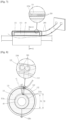
- FIG. 1 is a perspective view illustrating one example of the related art core assembly
- FIG. 2 is a sectional view illustrating a state that the core assembly of FIG. 1 is coupled to a pipe.
- the related art core assembly 1 includes cores 2 each provided with a pipe insertion recess 2a at a center thereof and having a semicircular sectional shape, core holders 3 each having a semicircular sectional shape and provided with a pipe insertion recess 3a, in which the corre-sponding core 2 is inserted, signal terminals 4 closely coupled onto both ends of an inner circumferential surface of one of the core holders 3, respectively, and a terminal pin 3b provided on one end of an outer circumferential surface of the one of the core holder 3 and allowing a connection with a connector 5, which is connected to each control board (not illustrated) via signal lines 5a.
- the core holders 3 are coupled to a gas pipe or a liquid pipe 6 (hereinafter, the gas pipe and the liquid pipe are collectively referred to as a refrigerant pipe and a reference numeral representatively denotes the liquid pipe) in a manner of surrounding the refrigerant pipe 6, such that the signal terminals 4 are closely adhered between an inner circumferential surface of each core holder 3 and an outer circumferential surface of the refrigerant pipe 6.
- a gas pipe or a liquid pipe 6 hereinafter, the gas pipe and the liquid pipe are collectively referred to as a refrigerant pipe and a reference numeral representatively denotes the liquid pipe
- the terminal pin 3b is provided at the one of the core holder 3, and an inner end of the terminal pin 3b is connected to the signal terminal 4. An outer end of the terminal pin 3b is electrically connected to the connector 5 which is inserted into the terminal pin 3b for connection. Accordingly, the signal terminal 4 coupled to the core assembly 1 and the signal line 5a extending from each control board are electrically connected to each other, such that electric signals between the control boards are transferred to the refrigerant pipe 6.
- KR 2011 0102032 A relates to an air conditioner that transmits signals using piping between an indoor unit and an outdoor unit, and more particularly to a core assembly of an air conditioner having an impedance to an electric signal.
- EP 1 318 355 A1 relates to an air conditioner having a humidifying unit, in which the amount of humidity can be maintained and the overall diameter of the lines can be designed to be minimized.
- WO 2012/099362 A2 relates to a piping communication system.
- EP 2 369 247 A2 relates to a communication apparatus, air conditioning system having the same and communication method thereof using refrigerant pipes.
- KR 2011 0019233 A relates to a signal transmitting device of an air conditioner comprising a core assembly and a signal terminal.
- US 2011/219795 A1 relates to a core assembly for an air conditioner, and an air conditioner having the same.
- the electric signal can be smoothly transferred only when the signal terminal 4 keeps on contacted by the refrigerant pipe 6.
- an assembly error of the core assembly 1 deterioration of the pipe or vibration causes the signal terminal 4 to be completely separated or intermittently spaced from the re-frigerant pipe 6, which results in a non-smooth signal transmission.
- the outdoor unit of the air conditioner is usually installed at an outside of a building. Accordingly, when the signal line 5a and the signal terminal 4 are connected to the terminal pin 3b, the connector 5 and the like, a breakdown or degradation of communication performance of the communication device is likely to be caused due to permeation of rainwater or foreign materials between the terminal pin 3b and the connector 5.
- an aspect of the detailed description is to provide a communication device for pipes, which is capable of maintaining high communication performance even without a direct contact between a signal terminal and a refrigerant pipe, and an air conditioner having the same.
- Another aspect of the detailed description is to provide a communication device for pipes, which is capable of preventing beforehand a breakdown or degradation of performance, caused due to rainwater or foreign materials even if being installed at an outside of a building, and an air conditioner having the same.
- the core assembly may have an annular sectional shape with both ends open, and the signal line may be inserted through the core assembly from one side opening end to the other side opening end.
- the signal line is wound by at least once on inner and outer circumferential surfaces of the core assembly.
- the core assembly may be provided with at least one through hole formed along a lengthwise direction thereof.
- the signal line is wound by passing through the inner circumferential surface of the core assembly and the through hole.
- the core assembly has a core made of a magnetic material, and an inner circumferential surface of the core may face an outer circumferential surface of the refrigerant pipe. Also, the signal line is located between the inner circumferential surface of the core and the outer circumferential surface of the refrigerant pipe.
- the core may have both side surfaces and an outer circumferential surface surrounded by a core holder made of an insulating material, and the core holder may be provided with a signal line mounting hole formed therethrough along a lengthwise direction thereof such that the signal line is inserted through the signal line mounting hole.
- the signal line mounting hole may be formed through each of outer and inner portions of the core holder based on the core
- a communication device for pipes of an air conditioner may transmit and receive communication signals using induced electromotive force, which is generated by winding a signal line around a core assembly. This may facilitate for connection between the core assembly and the signal line, without the need of a direct contact between a signal terminal and a refrigerant pipe.
- induced electromotive force which is generated by winding a signal line around a core assembly.
- connection between the signal line and the core assembly in the winding manner may prevent rainwater or foreign materials from permeating between the signal line and the core assembly, and accordingly prevent in advance a breakdown or degradation of communication performance due to the permeation.
- the signal line may be fixedly inserted through a signal line mounting hole, which is formed through the core assembly, thereby preventing in advance a movement of the core assembly even though the refrigerant pipe vibrates.
- FIG. 3 is a block diagram illustrating one exemplary embodiment of an air conditioner having a communication device for pipes in accordance with the present invention.
- an air conditioner may include an outdoor unit 10 and an indoor unit 20.
- the outdoor unit 10 and the indoor unit 20 may be located with interposing an outer wall of a building therebetween, and connected to each other through a gas pipe 30 and a liquid pipe 40.
- the outdoor unit 10 may include, within a case thereof, an outdoor unit-side heat exchanging unit 11, an outdoor unit-side controller 12, and an outdoor unit-side signal transfer unit 13.
- the indoor unit 20 may include, within a case thereof, an indoor unit-side heat exchanging unit 21, an indoor unit-side controller 22, and an indoor unit-side signal transfer unit 23.
- the outdoor unit-side controller 12 and the indoor unit-side controller 22 may exchange control signals through the medium of an alternating current (AC) signal.
- an AC control signal which is output from the outdoor unit-side controller 12 may be transmitted to the indoor unit-side controller 22 through the gas pipe 30 or the liquid pipe 40 or both of the pipes 30 and 40 via the outdoor unit-side signal transfer unit 13.
- an AC control signal which is output from the indoor unit-side controller 22 may be transmitted to the outdoor unit-side controller 12 through the gas pipe 30 or the liquid pipe 40 or both of the pipes 30 and 40 via the indoor unit-side signal transfer unit 23.
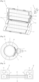
- FIG. 4 is a perspective view illustrating one exemplary embodiment of a core assembly of a signal transfer unit provided in an outdoor unit of the air conditioner illustrated in FIG. 3
- FIG. 5 is a front view illustrating a state that the core assembly illustrated in FIG. 4 is coupled to a pipe
- FIG. 6 is a sectional view taken along the line 'I-I' of FIG. 5 .
- the outdoor unit-side signal transfer unit installed in the liquid pipe will be representatively described.
- the signal transfer unit 13 includes a core assembly 100 coupled to surround the liquid pipe 40, and a signal line 200 wound around the core assembly 100 and having both ends connected to the outdoor unit-side controller 12.
- the core assembly 100 includes a core 110 made of a magnetic material and surrounding the liquid pipe 40, and a core holder 120 accommodating the core 110 therein such that the core 110 keeps on surrounding the liquid pipe 40 and simultaneously the signal line 200 is located between the liquid pipe 40 and the core 110.
- the core 110 may be implemented with a pair of partial cores 111 and 112 each of which is made of a magnetic material to generate single turn winding inductance and has a semicircular sectional shape.
- the shape of the core 110 may be formed to have various sectional shapes, such as a 1/4 circular sectional shape, as well as the semicircular sectional shape.
- the core 110 may be implemented as a troidal core.
- the AC signal when an AC signal flows along the liquid pipe 40 installed between the outdoor unit 10 and the indoor unit 20, the AC signal exhibits an attenuation characteristic according to a distance due to a transmission line impedance Z 0 of the pipe itself.
- the transmission line impedance Z 0 is proportional to the distance, and an AC signal which is used for sensing a distance of the liquid pipe 40 has reduced signal strength by the transmission line impedance Z 0 and the signal transfer unit 13. That is, if the impedance value of the signal transfer unit 13 and strength of AC control signals of transmitting and receiving ends are known, distance information may be obtained.
- the liquid pipe may be used as a transmission path of a distance sensing signal and this may allow for automatic calculation of a piping distance between the indoor unit and the outdoor unit, which is used for calculating an amount of refrigerant.
- the core holder 120 may also have a semicircular sectional shape, similar to the core 110.
- the core holder 120 may be divided into two parts along a center axis of a lengthwise direction thereof, so as to be formed with a plurality of partial holders 121 and 122 which are assembled into a cylindrical shape with accommodating the core 110 therebetween.
- the pair of partial holders 121 and 122 may be coupled by hinges at one side thereof in a widthwise direction so as to be rotatable with respect to each other.
- the pair of partial holders 121 and 122 may be provided with a plurality of coupling grooves 121b and a plurality of coupling protrusions 122b at the other side thereof, respectively, such that the pair of partial holders 121 and 122 can be detachably coupled to each other.
- the core may be integrally molded with the core holder.
- the core 110 and the core holder 120 are provided with pipe insertion recesses 111a, 112a, 121a and 122a formed at a center thereof to surround the liquid pipe 40.
- An inner diameter D2 of the pipe insertion recesses 111a and 112a may be formed greater than an outer diameter D1 of the liquid pipe 40, so as to be commonly applied to various standards of pipes.
- an elastic member (not illustrated) for supporting the core assembly 100 onto the liquid pipe 40 may be installed between an inner circumferential surface of the core assembly 100 (namely, the pipe insertion recesses) and an outer circumferential surface of the liquid pipe 40.
- the elastic member may be installed with a predetermined gap from along an inner circumferential surface of the core assembly such that a center of the elastic member and a center of the core assembly are aligned with each other.
- the elastic member may be installed eccentric to one side of the inner circumferential surface of the core assembly such that the center of the elastic member is eccentric from the center of the core assembly.
- the core holder 120 is wound by the signal line 200, without a separate signal terminal for electrical connection between the liquid pipe 40 and the signal line 200.
- the signal line 200 may be inserted from one side opening end 120a of the core holder 120, extend along an inner circumferential surface of the pipe insertion recesses 121a and 122a and then drawn out through the other opening end 120b, such that both ends thereof are electrically connected to the outdoor unit-side controller 12.
- the signal line 200 may also preferably be connected to the outdoor unit-side controller 12 after both ends thereof intersect with each other within the pipe insertion recesses 111a, 112a, 121a and 122a in a shape of surrounding the core holder 120 more than once from the outer circumferential surface to the inner circumferential surface of the core holder 120.
- a non-explained reference numeral 120c denotes a hinge.
- the pipe insertion recess 112a of the one partial core 112 and the pipe insertion recess 122a of the one partial holder 122 are inserted to be aligned with the liquid pipe 40.
- the partial core 111 and the partial holder 121 are rotated toward the other partial core 112 and the partial holder 122, and the coupling protrusions 122b of the other partial holder 122 are inserted into the coupling grooves 121b of the one partial holder 121 in an aligning manner.
- a communication signal of the outdoor unit-side controller 12 which is applied through the signal line 200 coupled to the core assembly 100 may be transmitted to the liquid pipe 40 using the induced electromotive force of the magnetic core 110 (the Lenz's law), and a communication signal which is applied from the indoor unit-side controller 22 to the liquid pipe 40 may be induced on the signal line 200 to be received by the outdoor unit-side controller 12.
- the connection between the core assembly and the signal line may be facilitated.
- the inner diameter of the pipe insertion recess of the core assembly may be formed greater than the outer diameter of the liquid pipe. This may allow one type of core assembly to be commonly applied to various standards of liquid pipes.
- the coupling between the signal line and the core assembly in the winding manner may prevent rainwater or foreign materials from permeating between the signal line and the core assembly even if a device, such as the outdoor unit, is installed at the outside of a building, accordingly minimizing a breakdown or degradation of communication performance of the communication device for pipes, which may be caused due to the permeation.
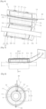
- FIG. 7 is a perspective view illustrating another exemplary embedment of the core holder illustrated in FIG. 4 .
- FIG. 8 is a sectional view taken along the line II-II in a state that the core holder illustrated in FIG. 7 is mounted to a liquid pipe.
- the foregoing embodiment has illustrated that the signal line is wound on the core holder after being inserted through the pipe insertion recesses, but this embodiment illustrates that a signal line mounting hole is formed through the core holder in a lengthwise direction of the core holder such that the signal line can be firmly, stably coupled to the core holder by being wound on the core holder.
- the core holder 120 may be provided with at least one signal line mounting hole 121d formed through each of an inner portion and an outer portion of the core holder 120 based on the core 110.
- the signal line 200 may be inserted into the signal line mounting hole 120d and firmly fixed thereto.
- the signal line mounting hole 120d may be formed in an arcuate shape such that the signal line can be wound therealong by plural times.
- a plurality of signal line mounting holes may be formed along a circumferential direction of the core holder 120, such that one string of signal line is inserted into each hole.
- the signal line may be inserted into the signal line mounting hole and firmly wound therealong, which may prevent the core assembly from moving even if a refrigerant pipe vibrates.
- a signal line mounting recess having a predetermined depth may also be formed in a thickness direction of the core holder along outer and inner circumferential surfaces of the core holder, instead of the signal line mounting hole.
- the signal line may be inserted into the signal line mounting recess so as to be fixed stably and firmly.
Landscapes
- Engineering & Computer Science (AREA)
- Chemical & Material Sciences (AREA)
- Combustion & Propulsion (AREA)
- Mechanical Engineering (AREA)
- General Engineering & Computer Science (AREA)
- Architecture (AREA)
- Civil Engineering (AREA)
- Structural Engineering (AREA)
- Human Computer Interaction (AREA)
- Air Conditioning Control Device (AREA)
- Air Filters, Heat-Exchange Apparatuses, And Housings Of Air-Conditioning Units (AREA)
Description
- The present invention relates to a communication device for pipes (or a signal transmission device) of an air conditioner, capable of transferring signals using pipes between indoor units and an outdoor unit.
- In general, an air conditioner is provided with an indoor unit and an outdoor unit, which are electrically connected such that electric signals can be transferred to each other. However, in case where a plurality of indoor units are connected in parallel to one outdoor unit or a refrigerant pipe is installed in a wall of a building and a plurality of indoor units are connected in parallel to the refrigerant pipe, it is usually difficult to electrically connect each of indoor units to outdoor units, number of which is less than the number of indoor units.
- Accordingly, a communication technology for pipes is being currently introduced to allow electric signals to be transmitted and received using a refrigerant pipe, as a communication medium, which connects a plurality of indoor units to a less number of outdoor units. For example, a communication device for pipes may be configured such that both ends of a gas-side refrigerant pipe (hereinafter, referred to as 'gas pipe' and both ends of a liquid-side refrigerant pipe (hereinafter, referred to as liquid pipe' are connected to indoor units and an outdoor unit, respectively, in an insulating manner, and signal lines which are connected to a control board of the indoor units and a control board of the outdoor unit are connected to the gas pipe and the liquid pipe. Consequently, the gas pipe and the liquid pipe can be used as communication media between the indoor units and the outdoor unit.
- Here, the refrigerant pipe is provided with a core assembly which is installed to increase communication performance. The core assembly is typically configured such that a pair of cores each having a semicircular section is accommodated in core holders and coupled to surround a refrigerant pipe, and the core holders are coupled to signal terminals which electrically connect the refrigerant pipe to each control board to each other. The signal terminals are fixed or detachably coupled to the core holders in a contact state with the refrigerant pipe.
-
FIG. 1 is a perspective view illustrating one example of the related art core assembly, andFIG. 2 is a sectional view illustrating a state that the core assembly ofFIG. 1 is coupled to a pipe. As illustrated inFIGS. 1 and 2 , the relatedart core assembly 1 includescores 2 each provided with apipe insertion recess 2a at a center thereof and having a semicircular sectional shape,core holders 3 each having a semicircular sectional shape and provided with a pipe insertion recess 3a, in which the corre-spondingcore 2 is inserted,signal terminals 4 closely coupled onto both ends of an inner circumferential surface of one of thecore holders 3, respectively, and aterminal pin 3b provided on one end of an outer circumferential surface of the one of thecore holder 3 and allowing a connection with a connector 5, which is connected to each control board (not illustrated) viasignal lines 5a. - In the
core assembly 1 according to the related art, thecore holders 3 are coupled to a gas pipe or a liquid pipe 6 (hereinafter, the gas pipe and the liquid pipe are collectively referred to as a refrigerant pipe and a reference numeral representatively denotes the liquid pipe) in a manner of surrounding the refrigerant pipe 6, such that thesignal terminals 4 are closely adhered between an inner circumferential surface of eachcore holder 3 and an outer circumferential surface of the refrigerant pipe 6. - The
terminal pin 3b is provided at the one of thecore holder 3, and an inner end of theterminal pin 3b is connected to thesignal terminal 4. An outer end of theterminal pin 3b is electrically connected to the connector 5 which is inserted into theterminal pin 3b for connection. Accordingly, thesignal terminal 4 coupled to thecore assembly 1 and thesignal line 5a extending from each control board are electrically connected to each other, such that electric signals between the control boards are transferred to the refrigerant pipe 6.
KR 2011 0102032 A
EP 1 318 355 A1
WO 2012/099362 A2 relates to a piping communication system.
EP 2 369 247 A2
KR 2011 0019233 A
US 2011/219795 A1 relates to a core assembly for an air conditioner, and an air conditioner having the same. - In the related art core assembly, the electric signal can be smoothly transferred only when the
signal terminal 4 keeps on contacted by the refrigerant pipe 6. However, an assembly error of thecore assembly 1, deterioration of the pipe or vibration causes thesignal terminal 4 to be completely separated or intermittently spaced from the re-frigerant pipe 6, which results in a non-smooth signal transmission. - Also, the outdoor unit of the air conditioner is usually installed at an outside of a building. Accordingly, when the
signal line 5a and thesignal terminal 4 are connected to theterminal pin 3b, the connector 5 and the like, a breakdown or degradation of communication performance of the communication device is likely to be caused due to permeation of rainwater or foreign materials between theterminal pin 3b and the connector 5. - Therefore, an aspect of the detailed description is to provide a communication device for pipes, which is capable of maintaining high communication performance even without a direct contact between a signal terminal and a refrigerant pipe, and an air conditioner having the same.
- Another aspect of the detailed description is to provide a communication device for pipes, which is capable of preventing beforehand a breakdown or degradation of performance, caused due to rainwater or foreign materials even if being installed at an outside of a building, and an air conditioner having the same.
- The invention is specified by the
independent claim 1. Preferred embodiments are defined in the dependent claims. - Here, the core assembly may have an annular sectional shape with both ends open, and the signal line may be inserted through the core assembly from one side opening end to the other side opening end.
- The signal line is wound by at least once on inner and outer circumferential surfaces of the core assembly.
- The core assembly may be provided with at least one through hole formed along a lengthwise direction thereof.
- The signal line is wound by passing through the inner circumferential surface of the core assembly and the through hole.
- The core assembly has a core made of a magnetic material, and an inner circumferential surface of the core may face an outer circumferential surface of the refrigerant pipe. Also, the signal line is located between the inner circumferential surface of the core and the outer circumferential surface of the refrigerant pipe.
- The core may have both side surfaces and an outer circumferential surface surrounded by a core holder made of an insulating material, and the core holder may be provided with a signal line mounting hole formed therethrough along a lengthwise direction thereof such that the signal line is inserted through the signal line mounting hole.
- The signal line mounting hole may be formed through each of outer and inner portions of the core holder based on the core
- A communication device for pipes of an air conditioner may transmit and receive communication signals using induced electromotive force, which is generated by winding a signal line around a core assembly. This may facilitate for connection between the core assembly and the signal line, without the need of a direct contact between a signal terminal and a refrigerant pipe. In addition, as an inner diameter of a pipe insertion recess of the core assembly is greater than an outer diameter of a refrigerant pipe, one type of core assembly can be commonly applied to various standards of refrigerant pipes.
- Also, even if the communication device is installed at the outside of a building, the connection between the signal line and the core assembly in the winding manner may prevent rainwater or foreign materials from permeating between the signal line and the core assembly, and accordingly prevent in advance a breakdown or degradation of communication performance due to the permeation.
- In addition, the signal line may be fixedly inserted through a signal line mounting hole, which is formed through the core assembly, thereby preventing in advance a movement of the core assembly even though the refrigerant pipe vibrates.
-
-
FIG. 1 is a perspective view illustrating one example of the related art core assembly. -
FIG. 2 is a sectional view illustrating a state that the core assembly ofFIG. 1 is coupled to a pipe. -
FIG. 3 is a block diagram illustrating one exemplary embodiment of an air conditioner having a communication device for pipes in accordance with the present invention. -
FIG. 4 is a perspective view illustrating one exemplary embodiment of a core assembly of a signal transfer unit provided in an outdoor unit of the air conditioner illustrated inFIG. 3 . -
FIG. 5 is a front view illustrating a state that the core assembly illustrated inFIG. 4 is coupled to a pipe. -
FIG. 6 is a sectional view taken along the line 'I-I' ofFIG. 5 . -
FIG. 7 is a perspective view illustrating another exemplary embedment of a core holder illustrated inFIG. 4 . -
FIG. 8 is a sectional view taken along the line 'II-II' in a state that the core holder illustrated inFIG. 7 is mounted to a liquid pipe. - Hereinafter, description will be given of a communication device for pipes (or a signal transmission device) of an air conditioner in accordance with one exemplary embodiment disclosed herein with reference to the accompanying drawings.
-
FIG. 3 is a block diagram illustrating one exemplary embodiment of an air conditioner having a communication device for pipes in accordance with the present invention. - As illustrated in
FIG. 3 , an air conditioner according to one exemplary embodiment may include anoutdoor unit 10 and anindoor unit 20. Theoutdoor unit 10 and theindoor unit 20 may be located with interposing an outer wall of a building therebetween, and connected to each other through agas pipe 30 and aliquid pipe 40. - The
outdoor unit 10 may include, within a case thereof, an outdoor unit-sideheat exchanging unit 11, an outdoor unit-side controller 12, and an outdoor unit-sidesignal transfer unit 13. Theindoor unit 20 may include, within a case thereof, an indoor unit-sideheat exchanging unit 21, an indoor unit-side controller 22, and an indoor unit-sidesignal transfer unit 23. - Here, the outdoor unit-
side controller 12 and the indoor unit-side controller 22 may exchange control signals through the medium of an alternating current (AC) signal. For example, an AC control signal which is output from the outdoor unit-side controller 12 may be transmitted to the indoor unit-side controller 22 through thegas pipe 30 or theliquid pipe 40 or both of thepipes signal transfer unit 13. On the other hand, an AC control signal which is output from the indoor unit-side controller 22 may be transmitted to the outdoor unit-side controller 12 through thegas pipe 30 or theliquid pipe 40 or both of thepipes signal transfer unit 23. -
FIG. 4 is a perspective view illustrating one exemplary embodiment of a core assembly of a signal transfer unit provided in an outdoor unit of the air conditioner illustrated inFIG. 3 ,FIG. 5 is a front view illustrating a state that the core assembly illustrated inFIG. 4 is coupled to a pipe, andFIG. 6 is a sectional view taken along the line 'I-I' ofFIG. 5 . Hereinafter, the outdoor unit-side signal transfer unit installed in the liquid pipe will be representatively described. - As illustrated in
FIG. 4 , thesignal transfer unit 13 according to this exemplary embodiment includes acore assembly 100 coupled to surround theliquid pipe 40, and asignal line 200 wound around thecore assembly 100 and having both ends connected to the outdoor unit-side controller 12. - The
core assembly 100 includes acore 110 made of a magnetic material and surrounding theliquid pipe 40, and acore holder 120 accommodating the core 110 therein such that thecore 110 keeps on surrounding theliquid pipe 40 and simultaneously thesignal line 200 is located between theliquid pipe 40 and thecore 110. - The
core 110 may be implemented with a pair ofpartial cores core 110 may be formed to have various sectional shapes, such as a 1/4 circular sectional shape, as well as the semicircular sectional shape. - The
core 110 may be implemented as a troidal core. For example, a troidal core which has an inner radius R1, an outer radius R2, a height h, and magnetic permeability µ, has a self inductance L of L= (µh/2π ln (R2/R1) and an impedance of Z = j2πfL with respect to an AC signal of a frequency f. Therefore, with respect to an AC control signal transmitted by the outdoor unit-side controller 12, a transmission line terminated with an impedance of 2*Z is formed at the side of the outdoor unit-sideheat exchanging unit 11 by an operation of the core through which theliquid pipe 40 penetrates. Therefore, when an AC signal flows along theliquid pipe 40 installed between theoutdoor unit 10 and theindoor unit 20, the AC signal exhibits an attenuation characteristic according to a distance due to a transmission line impedance Z0 of the pipe itself. And, the transmission line impedance Z0 is proportional to the distance, and an AC signal which is used for sensing a distance of theliquid pipe 40 has reduced signal strength by the transmission line impedance Z0 and thesignal transfer unit 13. That is, if the impedance value of thesignal transfer unit 13 and strength of AC control signals of transmitting and receiving ends are known, distance information may be obtained. Accordingly, the liquid pipe may be used as a transmission path of a distance sensing signal and this may allow for automatic calculation of a piping distance between the indoor unit and the outdoor unit, which is used for calculating an amount of refrigerant. - The
core holder 120 may also have a semicircular sectional shape, similar to thecore 110. Thecore holder 120 may be divided into two parts along a center axis of a lengthwise direction thereof, so as to be formed with a plurality ofpartial holders partial holders partial holders coupling protrusions 122b at the other side thereof, respectively, such that the pair ofpartial holders - Here, the
core 110 and thecore holder 120 are provided withpipe insertion recesses liquid pipe 40. An inner diameter D2 of thepipe insertion recesses liquid pipe 40, so as to be commonly applied to various standards of pipes. Here, in order to prevent thecore assembly 100 from freely spinning with respect to theliquid pipe 40, an elastic member (not illustrated) for supporting thecore assembly 100 onto theliquid pipe 40 may be installed between an inner circumferential surface of the core assembly 100 (namely, the pipe insertion recesses) and an outer circumferential surface of theliquid pipe 40. The elastic member may be installed with a predetermined gap from along an inner circumferential surface of the core assembly such that a center of the elastic member and a center of the core assembly are aligned with each other. Or, the elastic member may be installed eccentric to one side of the inner circumferential surface of the core assembly such that the center of the elastic member is eccentric from the center of the core assembly. - Meanwhile, the
core holder 120 is wound by thesignal line 200, without a separate signal terminal for electrical connection between theliquid pipe 40 and thesignal line 200. For example, thesignal line 200 may be inserted from oneside opening end 120a of thecore holder 120, extend along an inner circumferential surface of thepipe insertion recesses end 120b, such that both ends thereof are electrically connected to the outdoor unit-side controller 12. - Instead of the connection between the
signal line 200 and the outdoor unit-side controller 12 in a manner of inserting thesignal line 200 into the oneside opening end 120a of thecore holder 120, extending it through thepipe insertion recesses end 120b, in order to stably maintain the position of thesignal line 200 and simultaneously increase induced electromotive force, thesignal line 200 may also preferably be connected to the outdoor unit-side controller 12 after both ends thereof intersect with each other within thepipe insertion recesses core holder 120 more than once from the outer circumferential surface to the inner circumferential surface of thecore holder 120. - A
non-explained reference numeral 120c denotes a hinge. - Hereinafter, description will be given of operation effects of the communication device for pipes and the air conditioner according to the exemplary embodiments.
- That is, while the
partial holders hinges 120c of thecore holder 120, thepipe insertion recess 112a of the onepartial core 112 and thepipe insertion recess 122a of the onepartial holder 122 are inserted to be aligned with theliquid pipe 40. - Then, after winding the
signal line 200 in a lengthwise direction of thecore holder 120 along thepipe insertion recesses partial core 111 andpartial holder 121, thepartial core 111 and thepartial holder 121 are rotated toward the otherpartial core 112 and thepartial holder 122, and thecoupling protrusions 122b of the otherpartial holder 122 are inserted into the coupling grooves 121b of the onepartial holder 121 in an aligning manner. - A communication signal of the outdoor unit-
side controller 12 which is applied through thesignal line 200 coupled to thecore assembly 100 may be transmitted to theliquid pipe 40 using the induced electromotive force of the magnetic core 110 (the Lenz's law), and a communication signal which is applied from the indoor unit-side controller 22 to theliquid pipe 40 may be induced on thesignal line 200 to be received by the outdoor unit-side controller 12. - In this manner, as the signal line is coupled to the core assembly in a non-contact manner other than a contact manner, the connection between the core assembly and the signal line may be facilitated. In addition, the inner diameter of the pipe insertion recess of the core assembly may be formed greater than the outer diameter of the liquid pipe. This may allow one type of core assembly to be commonly applied to various standards of liquid pipes.
- Also, the coupling between the signal line and the core assembly in the winding manner may prevent rainwater or foreign materials from permeating between the signal line and the core assembly even if a device, such as the outdoor unit, is installed at the outside of a building, accordingly minimizing a breakdown or degradation of communication performance of the communication device for pipes, which may be caused due to the permeation.
- Hereinafter, description will be given of another exemplary embodiment of a core holder wound with a signal line in a communication device for pipes according to the present disclosure.
FIG. 7 is a perspective view illustrating another exemplary embedment of the core holder illustrated inFIG. 4 .FIG. 8 is a sectional view taken along the line II-II in a state that the core holder illustrated inFIG. 7 is mounted to a liquid pipe. - That is, the foregoing embodiment has illustrated that the signal line is wound on the core holder after being inserted through the pipe insertion recesses, but this embodiment illustrates that a signal line mounting hole is formed through the core holder in a lengthwise direction of the core holder such that the signal line can be firmly, stably coupled to the core holder by being wound on the core holder.
- For example, referring to
FIGS. 7 and 8 , thecore holder 120 according to this exemplary embodiment may be provided with at least one signalline mounting hole 121d formed through each of an inner portion and an outer portion of thecore holder 120 based on thecore 110. Thesignal line 200 may be inserted into the signalline mounting hole 120d and firmly fixed thereto. - The signal
line mounting hole 120d, as illustrated inFIG. 8 , may be formed in an arcuate shape such that the signal line can be wound therealong by plural times. In some cases, a plurality of signal line mounting holes may be formed along a circumferential direction of thecore holder 120, such that one string of signal line is inserted into each hole. - A configuration and operation effects of the core assembly according to this exemplary embodiment are the same or similar to those of the foregoing embodiment, so detailed description thereof will be omitted. Here, in this exemplary embodiment, the signal line may be inserted into the signal line mounting hole and firmly wound therealong, which may prevent the core assembly from moving even if a refrigerant pipe vibrates.
- Meanwhile, although not illustrated, a signal line mounting recess having a predetermined depth may also be formed in a thickness direction of the core holder along outer and inner circumferential surfaces of the core holder, instead of the signal line mounting hole. In this structure, the signal line may be inserted into the signal line mounting recess so as to be fixed stably and firmly.
Claims (9)
- A communication device for pipes of an air conditioner, the device comprising:a refrigerant pipe (40) for connecting an outdoor unit (10) and an indoor unit (20) to each other;a core assembly (100) comprising a core (110) made of a magnetic material and a core holder (120), the core assembly coupled to the refrigerant pipe (40) in a surrounding manner; anda signal line (200) that is configured to transfer electric signals transmitted and received through the refrigerant pipe (40) to controllers (12, 22) controlling the outdoor unit (10) and the indoor unit (20), respectively,the signal line (200) is inserted between the outer circumferential surface of the refrigerant pipe (40) and an inner circumferential surface of the core assembly (100) facing the outer circumferential surface of the refrigerant pipe (40), andthe signal line is configured to be electrically connected to the controllers (12, 22),characterized in thatthe signal line (200) is arranged within and outside a pipe insertion recesses (111a, 112a, 121a and 122a) of the core (110) and the core holder (120) in a shape of surrounding the core assembly (100) at least once from the outer circumferential surface to the inner circumferential surface of the core assembly (100).
- The device of claim 1, wherein the core assembly (100) has an annular sectional shape with both ends open, and the signal line (200) is inserted through the core assembly (100) from one side opening end to the other side opening end.
- The device of any one of claims 1 or 2, wherein the core assembly (100) is provided with at least one through hole formed along a lengthwise direction thereof.
- The device of claim 3, wherein the signal line (200) is passed through the through hole.
- The device of claim 1, wherein the core (110) has both side surfaces and an outer circumferential surface surrounded by a core holder (120) made of an insulating material, and the core holder (120) is provided with a signal line mounting hole (120d) formed therethrough along a lengthwise direction thereof such that the signal line (200) is wound by passing through the signal line mounting hole (120d).
- The device of claim 5, wherein the signal line mounting hole (120d) is formed through each of outer and inner portions of the core holder (120) based on the core (110).
- The device of any one of claims 1 to 6, wherein an inner diameter of the pipe insertion recess (111a, 112a, 121a, 122a) is greater than an outer diameter of the refrigerant pipe (40).
- The device of claim 7, wherein the core (110) has both side surfaces and an outer circumferential surface surrounded by a core holder (120) made of an insulating material, and the core holder (120) is provided with a signal line mounting hole (120d) formed therethrough along a lengthwise direction thereof such that the signal line (200) is inserted through the signal line mounting hole (120d).
- The device of claim 8, wherein the signal line (200) is wound by passing through the inner circumferential surface of the core assembly (100) and the signal line mounting hole (120d).
Applications Claiming Priority (2)
| Application Number | Priority Date | Filing Date | Title |
|---|---|---|---|
| KR1020130136464A KR102137020B1 (en) | 2013-11-11 | 2013-11-11 | Signal transmission device for air conditionner |
| PCT/KR2014/008619 WO2015068946A1 (en) | 2013-11-11 | 2014-09-16 | Signal transmission device for air conditioner |
Publications (3)
| Publication Number | Publication Date |
|---|---|
| EP3069085A1 EP3069085A1 (en) | 2016-09-21 |
| EP3069085A4 EP3069085A4 (en) | 2017-08-30 |
| EP3069085B1 true EP3069085B1 (en) | 2025-02-19 |
Family
ID=53041679
Family Applications (1)
| Application Number | Title | Priority Date | Filing Date |
|---|---|---|---|
| EP14859603.4A Active EP3069085B1 (en) | 2013-11-11 | 2014-09-16 | Signal transmission device for air conditioner |
Country Status (4)
| Country | Link |
|---|---|
| US (1) | US10381813B2 (en) |
| EP (1) | EP3069085B1 (en) |
| KR (1) | KR102137020B1 (en) |
| WO (1) | WO2015068946A1 (en) |
Families Citing this family (4)
| Publication number | Priority date | Publication date | Assignee | Title |
|---|---|---|---|---|
| KR102457214B1 (en) * | 2018-06-15 | 2022-10-21 | 삼성전자주식회사 | Air conditioner, and communication method of air conditioner using refrigerant piping |
| JP7404928B2 (en) * | 2020-02-25 | 2023-12-26 | 住友電装株式会社 | wire harness |
| CN112747388A (en) * | 2021-02-03 | 2021-05-04 | 珠海格力电器股份有限公司 | Air conditioner pipeline device and air conditioner |
| DE102021120848A1 (en) | 2021-08-11 | 2023-02-16 | Vaillant Gmbh | Process for the production of a cable bundle, cable bundle blank and air conditioning or heating system |
Family Cites Families (17)
| Publication number | Priority date | Publication date | Assignee | Title |
|---|---|---|---|---|
| US202047A (en) * | 1878-04-02 | Improvement in combined gas and electric conductors | ||
| US2530105A (en) * | 1945-12-17 | 1950-11-14 | Jr Robert Lee Wallace | Method of making a diver's combined hose and electrical communication line cable |
| US3111551A (en) * | 1960-05-13 | 1963-11-19 | Anaconda Wire & Cable Co | Fluid-cooled power cable |
| US3277231A (en) * | 1964-01-17 | 1966-10-04 | Electrolux Corp | Conductor-carrying flexible conduit |
| JPH0681996A (en) * | 1992-08-31 | 1994-03-22 | Matsushita Seiko Co Ltd | Refrigerant piping |
| JP2002089904A (en) | 2000-09-12 | 2002-03-27 | Daikin Ind Ltd | Air conditioner |
| EP2239520B1 (en) | 2004-03-09 | 2011-11-16 | Mitsubishi Denki Kabushiki Kaisha | Air conditioning equipment and signal transmission method therefor |
| JP5103778B2 (en) | 2006-04-17 | 2012-12-19 | ダイキン工業株式会社 | Air conditioning system |
| JP4762040B2 (en) | 2006-04-24 | 2011-08-31 | 三菱電機株式会社 | Transmission equipment, cooling / heating equipment and equipment |
| KR20100005295U (en) | 2008-11-14 | 2010-05-25 | 에어테크엔지니어링(주) | The Cover device |
| KR101257083B1 (en) * | 2009-08-19 | 2013-04-19 | 엘지전자 주식회사 | Signal delivery device for air conditionner |
| KR101257084B1 (en) * | 2010-03-10 | 2013-04-19 | 엘지전자 주식회사 | Signal transmission device for air conditionner |
| KR101229361B1 (en) | 2010-03-10 | 2013-02-05 | 엘지전자 주식회사 | Communicating apparatus, air conditioning system including the same and communicating method using refrigerant pipes thereof |
| KR101320510B1 (en) | 2010-03-10 | 2013-10-23 | 엘지전자 주식회사 | Core assembly |
| US20110219795A1 (en) | 2010-03-10 | 2011-09-15 | Chisun Ahn | Core assembly for air conditioner and air conditioner having the same |
| KR101088039B1 (en) | 2010-11-29 | 2011-11-30 | 소민철 | Refrigerant pipe for air conditioner and manufacturing method |
| KR101257095B1 (en) | 2011-01-21 | 2013-04-19 | 엘지전자 주식회사 | Piping cummunition system |
-
2013
- 2013-11-11 KR KR1020130136464A patent/KR102137020B1/en active Active
-
2014
- 2014-09-16 EP EP14859603.4A patent/EP3069085B1/en active Active
- 2014-09-16 US US15/031,971 patent/US10381813B2/en active Active
- 2014-09-16 WO PCT/KR2014/008619 patent/WO2015068946A1/en not_active Ceased
Also Published As
| Publication number | Publication date |
|---|---|
| EP3069085A1 (en) | 2016-09-21 |
| KR20150054252A (en) | 2015-05-20 |
| KR102137020B1 (en) | 2020-07-23 |
| EP3069085A4 (en) | 2017-08-30 |
| US20160273796A1 (en) | 2016-09-22 |
| US10381813B2 (en) | 2019-08-13 |
| WO2015068946A1 (en) | 2015-05-14 |
Similar Documents
| Publication | Publication Date | Title |
|---|---|---|
| US10381813B2 (en) | Signal transmission device for air conditioner | |
| EP1724534B1 (en) | Air conditioner, signal transmission method, and signal transmission method for air conditioner | |
| EP2366957B1 (en) | Core assembly for air conditioner and air conditioner having the same | |
| EP2665976B1 (en) | Piping communication system | |
| KR101257091B1 (en) | Signal Transmitter of Air Conditioner | |
| KR101257084B1 (en) | Signal transmission device for air conditionner | |
| KR101257083B1 (en) | Signal delivery device for air conditionner | |
| KR101320510B1 (en) | Core assembly | |
| KR101510119B1 (en) | Composite Cable For Power Line Communication | |
| KR20130107678A (en) | Communication network system in building using airconditioner pipe | |
| KR101257085B1 (en) | Signal delivery device for air conditionner | |
| KR101257096B1 (en) | Piping cummunition system | |
| CN113357852B (en) | Skeleton texture and have its electronic expansion valve | |
| KR101287965B1 (en) | Core assembly for air conditionner | |
| CN209874346U (en) | Wireless charging floor system | |
| JP2006038393A (en) | AIR CONDITIONER, SIGNAL TRANSMISSION METHOD, AND AIR CONDITIONER SIGNAL TRANSMISSION METHOD | |
| CN110676943A (en) | Electrical device | |
| KR20150093414A (en) | Wire integrated pipes, methods and apparatus for manufacturing the same | |
| KR101296791B1 (en) | Coaxial connecter | |
| WO2026083438A1 (en) | Sensor assembly | |
| KR200474434Y1 (en) | Communication network system in building using airconditioner pipe | |
| KR20160125817A (en) | Air-conditioner and pipe communication device |
Legal Events
| Date | Code | Title | Description |
|---|---|---|---|
| PUAI | Public reference made under article 153(3) epc to a published international application that has entered the european phase |
Free format text: ORIGINAL CODE: 0009012 |
|
| 17P | Request for examination filed |
Effective date: 20160611 |
|
| AK | Designated contracting states |
Kind code of ref document: A1 Designated state(s): AL AT BE BG CH CY CZ DE DK EE ES FI FR GB GR HR HU IE IS IT LI LT LU LV MC MK MT NL NO PL PT RO RS SE SI SK SM TR |
|
| AX | Request for extension of the european patent |
Extension state: BA ME |
|
| DAX | Request for extension of the european patent (deleted) | ||
| A4 | Supplementary search report drawn up and despatched |
Effective date: 20170728 |
|
| RIC1 | Information provided on ipc code assigned before grant |
Ipc: F24F 1/00 20110101ALI20170724BHEP Ipc: F24F 1/26 20110101ALI20170724BHEP Ipc: F24F 13/20 20060101ALI20170724BHEP Ipc: F24F 11/02 20060101AFI20170724BHEP Ipc: F24F 1/32 20110101ALI20170724BHEP |
|
| RAP1 | Party data changed (applicant data changed or rights of an application transferred) |
Owner name: LG ELECTRONICS INC. |
|
| STAA | Information on the status of an ep patent application or granted ep patent |
Free format text: STATUS: EXAMINATION IS IN PROGRESS |
|
| 17Q | First examination report despatched |
Effective date: 20200408 |
|
| REG | Reference to a national code |
Ref country code: DE Ref legal event code: R079 Free format text: PREVIOUS MAIN CLASS: F24F0011020000 Ipc: F24F0001260000 Ref document number: 602014091581 Country of ref document: DE |
|
| GRAP | Despatch of communication of intention to grant a patent |
Free format text: ORIGINAL CODE: EPIDOSNIGR1 |
|
| STAA | Information on the status of an ep patent application or granted ep patent |
Free format text: STATUS: GRANT OF PATENT IS INTENDED |
|
| RIC1 | Information provided on ipc code assigned before grant |
Ipc: F24F 11/89 20180101ALI20241104BHEP Ipc: F24F 11/56 20180101ALI20241104BHEP Ipc: F24F 1/32 20110101ALI20241104BHEP Ipc: F24F 1/26 20110101AFI20241104BHEP |
|
| INTG | Intention to grant announced |
Effective date: 20241115 |
|
| GRAS | Grant fee paid |
Free format text: ORIGINAL CODE: EPIDOSNIGR3 |
|
| GRAA | (expected) grant |
Free format text: ORIGINAL CODE: 0009210 |
|
| STAA | Information on the status of an ep patent application or granted ep patent |
Free format text: STATUS: THE PATENT HAS BEEN GRANTED |
|
| AK | Designated contracting states |
Kind code of ref document: B1 Designated state(s): AL AT BE BG CH CY CZ DE DK EE ES FI FR GB GR HR HU IE IS IT LI LT LU LV MC MK MT NL NO PL PT RO RS SE SI SK SM TR |
|
| REG | Reference to a national code |
Ref country code: GB Ref legal event code: FG4D |
|
| REG | Reference to a national code |
Ref country code: CH Ref legal event code: EP |
|
| REG | Reference to a national code |
Ref country code: DE Ref legal event code: R096 Ref document number: 602014091581 Country of ref document: DE |
|
| REG | Reference to a national code |
Ref country code: IE Ref legal event code: FG4D |
|
| REG | Reference to a national code |
Ref country code: NL Ref legal event code: MP Effective date: 20250219 |
|
| PG25 | Lapsed in a contracting state [announced via postgrant information from national office to epo] |
Ref country code: RS Free format text: LAPSE BECAUSE OF FAILURE TO SUBMIT A TRANSLATION OF THE DESCRIPTION OR TO PAY THE FEE WITHIN THE PRESCRIBED TIME-LIMIT Effective date: 20250519 |
|
| PG25 | Lapsed in a contracting state [announced via postgrant information from national office to epo] |
Ref country code: FI Free format text: LAPSE BECAUSE OF FAILURE TO SUBMIT A TRANSLATION OF THE DESCRIPTION OR TO PAY THE FEE WITHIN THE PRESCRIBED TIME-LIMIT Effective date: 20250219 |
|
| PG25 | Lapsed in a contracting state [announced via postgrant information from national office to epo] |
Ref country code: PL Free format text: LAPSE BECAUSE OF FAILURE TO SUBMIT A TRANSLATION OF THE DESCRIPTION OR TO PAY THE FEE WITHIN THE PRESCRIBED TIME-LIMIT Effective date: 20250219 |
|
| PG25 | Lapsed in a contracting state [announced via postgrant information from national office to epo] |
Ref country code: ES Free format text: LAPSE BECAUSE OF FAILURE TO SUBMIT A TRANSLATION OF THE DESCRIPTION OR TO PAY THE FEE WITHIN THE PRESCRIBED TIME-LIMIT Effective date: 20250219 |
|
| REG | Reference to a national code |
Ref country code: LT Ref legal event code: MG9D |
|
| PG25 | Lapsed in a contracting state [announced via postgrant information from national office to epo] |
Ref country code: NO Free format text: LAPSE BECAUSE OF FAILURE TO SUBMIT A TRANSLATION OF THE DESCRIPTION OR TO PAY THE FEE WITHIN THE PRESCRIBED TIME-LIMIT Effective date: 20250519 Ref country code: IS Free format text: LAPSE BECAUSE OF FAILURE TO SUBMIT A TRANSLATION OF THE DESCRIPTION OR TO PAY THE FEE WITHIN THE PRESCRIBED TIME-LIMIT Effective date: 20250619 |
|
| PG25 | Lapsed in a contracting state [announced via postgrant information from national office to epo] |
Ref country code: NL Free format text: LAPSE BECAUSE OF FAILURE TO SUBMIT A TRANSLATION OF THE DESCRIPTION OR TO PAY THE FEE WITHIN THE PRESCRIBED TIME-LIMIT Effective date: 20250219 |
|
| PG25 | Lapsed in a contracting state [announced via postgrant information from national office to epo] |
Ref country code: HR Free format text: LAPSE BECAUSE OF FAILURE TO SUBMIT A TRANSLATION OF THE DESCRIPTION OR TO PAY THE FEE WITHIN THE PRESCRIBED TIME-LIMIT Effective date: 20250219 |
|
| PG25 | Lapsed in a contracting state [announced via postgrant information from national office to epo] |
Ref country code: LV Free format text: LAPSE BECAUSE OF FAILURE TO SUBMIT A TRANSLATION OF THE DESCRIPTION OR TO PAY THE FEE WITHIN THE PRESCRIBED TIME-LIMIT Effective date: 20250219 Ref country code: PT Free format text: LAPSE BECAUSE OF FAILURE TO SUBMIT A TRANSLATION OF THE DESCRIPTION OR TO PAY THE FEE WITHIN THE PRESCRIBED TIME-LIMIT Effective date: 20250620 |
|
| PG25 | Lapsed in a contracting state [announced via postgrant information from national office to epo] |
Ref country code: GR Free format text: LAPSE BECAUSE OF FAILURE TO SUBMIT A TRANSLATION OF THE DESCRIPTION OR TO PAY THE FEE WITHIN THE PRESCRIBED TIME-LIMIT Effective date: 20250520 Ref country code: BG Free format text: LAPSE BECAUSE OF FAILURE TO SUBMIT A TRANSLATION OF THE DESCRIPTION OR TO PAY THE FEE WITHIN THE PRESCRIBED TIME-LIMIT Effective date: 20250219 |
|
| REG | Reference to a national code |
Ref country code: AT Ref legal event code: MK05 Ref document number: 1768577 Country of ref document: AT Kind code of ref document: T Effective date: 20250219 |
|
| PG25 | Lapsed in a contracting state [announced via postgrant information from national office to epo] |
Ref country code: SE Free format text: LAPSE BECAUSE OF FAILURE TO SUBMIT A TRANSLATION OF THE DESCRIPTION OR TO PAY THE FEE WITHIN THE PRESCRIBED TIME-LIMIT Effective date: 20250219 |
|
| PG25 | Lapsed in a contracting state [announced via postgrant information from national office to epo] |
Ref country code: SM Free format text: LAPSE BECAUSE OF FAILURE TO SUBMIT A TRANSLATION OF THE DESCRIPTION OR TO PAY THE FEE WITHIN THE PRESCRIBED TIME-LIMIT Effective date: 20250219 |
|
| PG25 | Lapsed in a contracting state [announced via postgrant information from national office to epo] |
Ref country code: DK Free format text: LAPSE BECAUSE OF FAILURE TO SUBMIT A TRANSLATION OF THE DESCRIPTION OR TO PAY THE FEE WITHIN THE PRESCRIBED TIME-LIMIT Effective date: 20250219 |
|
| PGFP | Annual fee paid to national office [announced via postgrant information from national office to epo] |
Ref country code: DE Payment date: 20250805 Year of fee payment: 12 |
|
| PG25 | Lapsed in a contracting state [announced via postgrant information from national office to epo] |
Ref country code: IT Free format text: LAPSE BECAUSE OF FAILURE TO SUBMIT A TRANSLATION OF THE DESCRIPTION OR TO PAY THE FEE WITHIN THE PRESCRIBED TIME-LIMIT Effective date: 20250219 |
|
| PG25 | Lapsed in a contracting state [announced via postgrant information from national office to epo] |
Ref country code: AT Free format text: LAPSE BECAUSE OF FAILURE TO SUBMIT A TRANSLATION OF THE DESCRIPTION OR TO PAY THE FEE WITHIN THE PRESCRIBED TIME-LIMIT Effective date: 20250219 |
|
| PG25 | Lapsed in a contracting state [announced via postgrant information from national office to epo] |
Ref country code: EE Free format text: LAPSE BECAUSE OF FAILURE TO SUBMIT A TRANSLATION OF THE DESCRIPTION OR TO PAY THE FEE WITHIN THE PRESCRIBED TIME-LIMIT Effective date: 20250219 Ref country code: CZ Free format text: LAPSE BECAUSE OF FAILURE TO SUBMIT A TRANSLATION OF THE DESCRIPTION OR TO PAY THE FEE WITHIN THE PRESCRIBED TIME-LIMIT Effective date: 20250219 |
|
| PG25 | Lapsed in a contracting state [announced via postgrant information from national office to epo] |
Ref country code: RO Free format text: LAPSE BECAUSE OF FAILURE TO SUBMIT A TRANSLATION OF THE DESCRIPTION OR TO PAY THE FEE WITHIN THE PRESCRIBED TIME-LIMIT Effective date: 20250219 |
|
| PG25 | Lapsed in a contracting state [announced via postgrant information from national office to epo] |
Ref country code: SK Free format text: LAPSE BECAUSE OF FAILURE TO SUBMIT A TRANSLATION OF THE DESCRIPTION OR TO PAY THE FEE WITHIN THE PRESCRIBED TIME-LIMIT Effective date: 20250219 |
|
| REG | Reference to a national code |
Ref country code: DE Ref legal event code: R097 Ref document number: 602014091581 Country of ref document: DE |
|
| PLBE | No opposition filed within time limit |
Free format text: ORIGINAL CODE: 0009261 |
|
| STAA | Information on the status of an ep patent application or granted ep patent |
Free format text: STATUS: NO OPPOSITION FILED WITHIN TIME LIMIT |
|
| REG | Reference to a national code |
Ref country code: CH Ref legal event code: L10 Free format text: ST27 STATUS EVENT CODE: U-0-0-L10-L00 (AS PROVIDED BY THE NATIONAL OFFICE) Effective date: 20251231 |
|
| 26N | No opposition filed |
Effective date: 20251120 |
|
| REG | Reference to a national code |
Ref country code: CH Ref legal event code: H13 Free format text: ST27 STATUS EVENT CODE: U-0-0-H10-H13 (AS PROVIDED BY THE NATIONAL OFFICE) Effective date: 20260504 |