EP3068278B1 - Liquid presence/turbidity sensor using single optical channel - Google Patents
Liquid presence/turbidity sensor using single optical channel Download PDFInfo
- Publication number
- EP3068278B1 EP3068278B1 EP14790985.7A EP14790985A EP3068278B1 EP 3068278 B1 EP3068278 B1 EP 3068278B1 EP 14790985 A EP14790985 A EP 14790985A EP 3068278 B1 EP3068278 B1 EP 3068278B1
- Authority
- EP
- European Patent Office
- Prior art keywords
- electronic light
- multisensor
- lenses
- light
- fluid
- Prior art date
- Legal status (The legal status is an assumption and is not a legal conclusion. Google has not performed a legal analysis and makes no representation as to the accuracy of the status listed.)
- Active
Links
- 0 C*1*=C=CC1*C*CI Chemical compound C*1*=C=CC1*C*CI 0.000 description 2
Images



Classifications
-
- G—PHYSICS
- G01—MEASURING; TESTING
- G01N—INVESTIGATING OR ANALYSING MATERIALS BY DETERMINING THEIR CHEMICAL OR PHYSICAL PROPERTIES
- G01N21/00—Investigating or analysing materials by the use of optical means, i.e. using sub-millimetre waves, infrared, visible or ultraviolet light
- G01N21/17—Systems in which incident light is modified in accordance with the properties of the material investigated
- G01N21/47—Scattering, i.e. diffuse reflection
- G01N21/49—Scattering, i.e. diffuse reflection within a body or fluid
- G01N21/53—Scattering, i.e. diffuse reflection within a body or fluid within a flowing fluid, e.g. smoke
- G01N21/532—Scattering, i.e. diffuse reflection within a body or fluid within a flowing fluid, e.g. smoke with measurement of scattering and transmission
-
- D—TEXTILES; PAPER
- D06—TREATMENT OF TEXTILES OR THE LIKE; LAUNDERING; FLEXIBLE MATERIALS NOT OTHERWISE PROVIDED FOR
- D06F—LAUNDERING, DRYING, IRONING, PRESSING OR FOLDING TEXTILE ARTICLES
- D06F34/00—Details of control systems for washing machines, washer-dryers or laundry dryers
- D06F34/14—Arrangements for detecting or measuring specific parameters
- D06F34/22—Condition of the washing liquid, e.g. turbidity
-
- G—PHYSICS
- G01—MEASURING; TESTING
- G01N—INVESTIGATING OR ANALYSING MATERIALS BY DETERMINING THEIR CHEMICAL OR PHYSICAL PROPERTIES
- G01N21/00—Investigating or analysing materials by the use of optical means, i.e. using sub-millimetre waves, infrared, visible or ultraviolet light
- G01N21/17—Systems in which incident light is modified in accordance with the properties of the material investigated
- G01N21/41—Refractivity; Phase-affecting properties, e.g. optical path length
-
- G—PHYSICS
- G01—MEASURING; TESTING
- G01N—INVESTIGATING OR ANALYSING MATERIALS BY DETERMINING THEIR CHEMICAL OR PHYSICAL PROPERTIES
- G01N21/00—Investigating or analysing materials by the use of optical means, i.e. using sub-millimetre waves, infrared, visible or ultraviolet light
- G01N21/17—Systems in which incident light is modified in accordance with the properties of the material investigated
- G01N21/47—Scattering, i.e. diffuse reflection
- G01N21/49—Scattering, i.e. diffuse reflection within a body or fluid
- G01N21/53—Scattering, i.e. diffuse reflection within a body or fluid within a flowing fluid, e.g. smoke
- G01N21/534—Scattering, i.e. diffuse reflection within a body or fluid within a flowing fluid, e.g. smoke by measuring transmission alone, i.e. determining opacity
-
- G—PHYSICS
- G01—MEASURING; TESTING
- G01N—INVESTIGATING OR ANALYSING MATERIALS BY DETERMINING THEIR CHEMICAL OR PHYSICAL PROPERTIES
- G01N21/00—Investigating or analysing materials by the use of optical means, i.e. using sub-millimetre waves, infrared, visible or ultraviolet light
- G01N21/17—Systems in which incident light is modified in accordance with the properties of the material investigated
- G01N21/59—Transmissivity
-
- G—PHYSICS
- G01—MEASURING; TESTING
- G01N—INVESTIGATING OR ANALYSING MATERIALS BY DETERMINING THEIR CHEMICAL OR PHYSICAL PROPERTIES
- G01N21/00—Investigating or analysing materials by the use of optical means, i.e. using sub-millimetre waves, infrared, visible or ultraviolet light
- G01N21/17—Systems in which incident light is modified in accordance with the properties of the material investigated
- G01N21/59—Transmissivity
- G01N21/5907—Densitometers
-
- G—PHYSICS
- G01—MEASURING; TESTING
- G01N—INVESTIGATING OR ANALYSING MATERIALS BY DETERMINING THEIR CHEMICAL OR PHYSICAL PROPERTIES
- G01N21/00—Investigating or analysing materials by the use of optical means, i.e. using sub-millimetre waves, infrared, visible or ultraviolet light
- G01N21/84—Systems specially adapted for particular applications
- G01N21/85—Investigating moving fluids or granular solids
- G01N21/8507—Probe photometers, i.e. with optical measuring part dipped into fluid sample
-
- A—HUMAN NECESSITIES
- A47—FURNITURE; DOMESTIC ARTICLES OR APPLIANCES; COFFEE MILLS; SPICE MILLS; SUCTION CLEANERS IN GENERAL
- A47L—DOMESTIC WASHING OR CLEANING; SUCTION CLEANERS IN GENERAL
- A47L15/00—Washing or rinsing machines for crockery or tableware
- A47L15/42—Details
- A47L15/4297—Arrangements for detecting or measuring the condition of the washing water, e.g. turbidity
-
- D—TEXTILES; PAPER
- D06—TREATMENT OF TEXTILES OR THE LIKE; LAUNDERING; FLEXIBLE MATERIALS NOT OTHERWISE PROVIDED FOR
- D06F—LAUNDERING, DRYING, IRONING, PRESSING OR FOLDING TEXTILE ARTICLES
- D06F2103/00—Parameters monitored or detected for the control of domestic laundry washing machines, washer-dryers or laundry dryers
- D06F2103/20—Washing liquid condition, e.g. turbidity
-
- D—TEXTILES; PAPER
- D06—TREATMENT OF TEXTILES OR THE LIKE; LAUNDERING; FLEXIBLE MATERIALS NOT OTHERWISE PROVIDED FOR
- D06F—LAUNDERING, DRYING, IRONING, PRESSING OR FOLDING TEXTILE ARTICLES
- D06F2105/00—Systems or parameters controlled or affected by the control systems of washing machines, washer-dryers or laundry dryers
- D06F2105/52—Changing sequence of operational steps; Carrying out additional operational steps; Modifying operational steps, e.g. by extending duration of steps
-
- D—TEXTILES; PAPER
- D06—TREATMENT OF TEXTILES OR THE LIKE; LAUNDERING; FLEXIBLE MATERIALS NOT OTHERWISE PROVIDED FOR
- D06F—LAUNDERING, DRYING, IRONING, PRESSING OR FOLDING TEXTILE ARTICLES
- D06F33/00—Control of operations performed in washing machines or washer-dryers
- D06F33/30—Control of washing machines characterised by the purpose or target of the control
- D06F33/32—Control of operational steps, e.g. optimisation or improvement of operational steps depending on the condition of the laundry
-
- G—PHYSICS
- G01—MEASURING; TESTING
- G01N—INVESTIGATING OR ANALYSING MATERIALS BY DETERMINING THEIR CHEMICAL OR PHYSICAL PROPERTIES
- G01N2201/00—Features of devices classified in G01N21/00
- G01N2201/06—Illumination; Optics
- G01N2201/062—LED's
-
- G—PHYSICS
- G01—MEASURING; TESTING
- G01N—INVESTIGATING OR ANALYSING MATERIALS BY DETERMINING THEIR CHEMICAL OR PHYSICAL PROPERTIES
- G01N2201/00—Features of devices classified in G01N21/00
- G01N2201/06—Illumination; Optics
- G01N2201/063—Illuminating optical parts
- G01N2201/0638—Refractive parts
Definitions
- the present invention relates to a multisensor for the measurement of both of the turbidity of liquid and the presence the liquid in a sensing volume as defined in claim 1.
- the present invention relates also to an appliance as defined in claim 12.
- US 2007/0151584 A1 discloses a system distinguishing between air, foam, and water. It can, however, not distinguish between water and turbid water. The distinction between water and foam is based on a change in light over time.
- US 4 637 719 A , DE 10 2006 052 892 A1 , EP 0 393 311 A1 and US 2013/092189 A1 describe turbidity sensors which, however, do not use optical elements in contact with liquid in the channel that change their index of refraction as with the present invention.
- Optical sensors may be used to detect the presence or absence of a liquid, for example, in a washing machine or dishwasher and for determining the turbidity of that liquid when liquid is present. Such turbidity measurements may indicate the amount of dirt suspended in the water and may be used to assess how much cleaning or rinsing is required.
- the turbidity of a liquid in a sampling volume may be measured by assessing how much light passes between a light transmitter and light detector positioned so that the path of light between the light transmitter and light detector crosses the sampling volume.
- the light transmitter may be an electronic light source such as a light emitting diode and the light detector may be an electronic light sensor such as a photodiode, phototransistor, or the like.
- the amount of light passing between the light transmitter and light detector in a turbidity sensor will also be affected by whether the sampling volume contains air or water. Air in the sampling volume will typically reduce the amount of light passing between the light transmitter and light detector when compared to the light transmitted by a clear liquid. This is because the turbidity sensor normally includes optical elements configured to maximize light transmission in liquid to ensure sufficient light is transmitted for measurement of highly turbid water. As a result, a turbidity sensor with a single optical channel (for example, one light transmitter and one light detector) cannot reliably distinguish between air and turbid water.
- Multisensors which combine a liquid presence sensor and a turbidity sensor normally use two optical channels each producing independent signals.
- the first channel may provide a straight transmission path through the sampling volume between a first light transmitter/receiver pair to deduce turbidity.
- the second channel may provide a transmission path reflecting off a boundary between an optical element and material in the sampling volume between the second light transmitter/receiver pair.
- the optical element will provide for a greater internal reflection when air is in the sampling volume than when water is in the sampling volume thus reliably distinguishing between air and liquid.
- These two optical channels may share one of optical transmitters or receivers, for example, through multiplexing techniques, but generally require at least three components selected from optical transmitters and receivers and two optical paths.
- a single optical channel can be used to detect turbidity and to detect the presence or absence of liquid by ensuring that the attenuation of the light in this optical channel is less for air than it is for clear water.
- this relative attenuation is enforced by focusing the light between the light transmitter and the light detector using refractive elements under the assumption that the refractive elements are in an air environment. The introduction of water into that environment upsets this assumption and de-focuses these refractive elements reducing the light intensity at the light detector.
- the present invention provides a multisensory as defined in claim 1 and an appliance as defined in claim 12.
- the optical element may be a focusing lens positioned along the optical path to be in contact with fluid in the passage.
- the turbidity sensor may employ two lenses positioned along the optical path to be in contact with fluid from the passage wherein the lenses are positioned and focused to provide the first level of transmission of light from the electronic light source to the electronic light detector when the fluid in the passage is air and the second level of transmission of light from the electronic light source to the electronic light detector when the fluid in the passage is clear water, the first level of transmission of light being greater than the second level of transmission of light.
- the lenses may be circular lenses selected from the group consisting of circular plano-convex lenses and bi-convex lenses.
- the lenses may be cylindrical or sphero-cylindrical lenses.
- the turbidity sensor may include detection circuitry for detecting at least three levels of light transmission corresponding to the fluid in the passage being air, the fluid in the passage being water of low turbidity and the fluid in the passage being water of high turbidity, higher than the low turbidity.
- the turbidity sensor may include only a single electronic light source and single electronic light detector.
- a multisensor 10 per the present invention may provide a U-shaped frame 12 having opposed arms 14a and 14b extending in opposition across a fluid passage 16.
- the first arm 14a may hold at a distal end a light transmitter 18, for example, providing a light source, and including but not limited to a light emitting diode die or light emitting diode die plus encapsulating lens element.
- the light transmitter 18 directs light along optical axis 20 through the fluid passage 16 toward a distal end of the second arm 14b.
- the second arm 14b may in turn hold at a distal end a light detector 22, for example, a photosensor such as a photodiode, photo transistor, a photo resistor, or photocell, receiving light along the optical axis 20 through the fluid passage 16 from the first arms 14a.
- a light detector 22 for example, a photosensor such as a photodiode, photo transistor, a photo resistor, or photocell, receiving light along the optical axis 20 through the fluid passage 16 from the first arms 14a.
- the photosensor may include some integrated optical lenses or may be a die without lens.
- a collimating lens 24 may be positioned along the optical axis 20 between the light transmitter 18 within the arm 14a and an external fluid 26 in the fluid passage 16.
- a focusing lens 28 may be positioned along the optical axis 20 between the external fluid 26 in the fluid passage 16 and the light detector 22 in the arm 14b.
- both the collimating lens 24 and focusing lens 28 will contact the external fluid 26 such as may modify the focal properties of the collimating lens 24 and the focusing lens 28 by changing the difference in index of refraction between the optical material of the lenses 24 and 28 and the surrounding medium such as changes refraction.
- the light transmitter 18 may communicate via leads 30 passing within the arm 14a to a source of electrical power and the light detector 22 may communicate via leads 32 passing within the arm 14b to detection circuitry for determining an amount of light received by the light detector 22.
- the collimating lens 24 and the focusing lens 28 may be sealed to the respective arms 14a and 14b to prevent fluid from leaking into the arms 14 which are otherwise sealed against fluid ingress.
- the arms 14 may attach to a base 19 that includes a seal 17 allowing the base 19 to be attached through an opening and sealed to the opening in a channel containing a stream of liquid flow of external liquid 26 to prevent leakage therefrom so that the arms 14 extend into the liquid flow and the leads 30 and 32 are accessible outside of the channel from an opposite side of the base 19.
- collimating lens 24 and focusing lens 28 transmit an image of a surface of the light transmitter 18 originating at a first focal plane 34 to a second focal plane 36 focused on the surface of the light detector 22.
- collimating lens 24, focusing lens 28, and the geometry of the focal planes 34 and 36 and the positions of the lenses 24 and 28 are selected according to well understood optical principles to provide this focusing with air 33 within the fluid passage 16.
- this focusing described above is dependent on the focal length of the lenses 24 and 28, the latter of which is generally determined by the difference between the index of refraction of the lens material and the index of refraction of the medium surrounding the lens and in particular the media in the fluid passage 16.
- a compact illumination spot 38 (shown displaced from light detector 22 and rotated 90 degrees for clarity) will generally conform to an image of the light transmitter 18 concentrating and maximizing the light energy from the light transmitter 18 on the active area of the light detector 22.
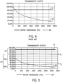
- This will produce a detector output, for example, of 180 percent, as referenced to a detector output of 100 percent expected when clear liquid water is within the fluid passage 16 as shown in Fig. 5 by curve 51.
- This output is independent of the turbidity of water (shown in the horizontal axis of Fig. 5 ) simply because water is not positioned between the light transmitter 18 and the light detector 22 in this environment 37.
- collimating lens 24 and focusing lens 28 transmit an image of a surface of the light transmitter 18 at a second focal plane 42 past the surface of the light detector 22.
- the illumination spot 38' on the light detector 22 will be an unfocused image of the light transmitter 18 and thus be larger to extend outside the boundaries of the light detector 22 and more diffuse within the boundaries of the light detector 22, reducing the amount of light detected by the light detector 22 to a value of 100 percent (normalized to this water transmission path) which is, importantly, lower than that obtained when air 33 is within the fluid passage 16 as shown in environment 37.
- a range of varying turbidity will provide a corresponding range of varying attenuation in detected light along a curve 50 in a plot of light attenuation vs. turbidity that may be used to provide a quantitative output of turbidity.
- the chart shown in Fig. 5 may be contrasted with the chart in Fig. 4 showing a prior art system without the focused optics of the present invention such as produces an overlap between curve 51' corresponding to curve 51 and curve 50' corresponding to curve 50.
- the presence of air between the light transmitter 18 and light detector 22 cannot be distinguished from the presence of water between the light transmitter 18 and the light detector 22 if the water has an NTU value of approximately 200.
- the practical effect is that the presence of air or water may not be adequately distinguish over an important range of turbidity.
- the chart of Fig. 5 shows that the presence of air may be readily distinguished from the presence of water at all turbidity levels.
- the light transmitter 18 and light detector 22 may include optional ancillary lenses 35, for example, incorporated into the packages of the light transmitter 18 and/or light detector 22 or other lenses may be placed along the optical path. Generally these lenses will not be in contact with fluid in the fluid passage 16. The focusing effect of these ancillary lenses 35 is simply accommodated in the placement and focusing of the lenses 24 and 28 to provide the desired detection effect described above.
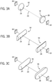
- various optical systems may be used in the present invention including circular plano-convex lenses or biconvex lenses 52 as shown in Fig. 3a , cylindrical lenses 54 as shown in Fig. 3b and sphero-cylindrical lenses 55 as shown in Fig. 3c .
- a cylindrical lens 54 is one having a surface that is a portion of a cylinder.
- a sphero-cylindrical lens 55 is one having different portions of its surface that are portions of spheres (for example, the ends of the lens) and other portions that are portions of a cylinder. Any of these lenses may be solid surface or Fresnel versions. It is contemplated that the lenses will be injection molded but other fabrication techniques may be employed.
- the lenses may be integrally molded into opposed faces of the arms 14.
- Each of these lenses 52, 54, and 55 may be configured to provide a concentrated focusing of light from the light transmitter 18 on the light detector 22, and thus a maximum light detected at light detector 22 in the presence of air along the optical axis 20, and a lesser focusing and lower light detected at light detector 22 even with perfectly clear water and decreasing with increased water turbidity.
- a control circuit 49 suitable for the present sensor may provide for a biasing circuit 56 for the light transmitter 18 and a biasing circuit 57 for the light detector 22 both operating from a common power line 58. Fluctuations in the power, for example, incident to unregulated power in a home appliance or the like may be accommodated by also providing a comparator system 59 that generates threshold voltages 61 from the power line 58. In this way, common mode variations in the power line 88 cause the threshold voltages to rise and fall together with the biasing of the light transmitter 18 and light detector 22 to offset this effect.
- the generated threshold voltages may provide for two threshold voltages V 1 and V 2 provided to separate comparators 63a and 63b which also receive an output from the light detector.
- these threshold voltages V 1 and V 2 may distinguish curve 51 from curve 50 at all turbidities and distinguish a high and low turbidity value on curve 50 such as may trigger a washing process.
- the voltage V 1 defines above it, a first range 53 of light transmission indicative of the presence of air between the light transmitter 18 and light detector 22, and the voltage V 1 defines below it a second range 65 associated only with the presence of water between the light transmitter 18 and light detector 22.
- the voltage V 2 divides the second range 65 into a first sub range 65a associated with a first turbidity and the second sub range 65b associated with a second turbidity.
- first and second sub ranges 65a and 65b may be used to control the washing cycles of the appliance selecting between light and heavy cycles while the first range 53 may be used to determine that the water is present or absent at the beginning or end of the cycles to ensure that a washing chamber is filled or emptied as the case may be.
- the multisensor 10 of the present invention may be positioned in a fluid conduit as part of a washing appliance 60 having a washing chamber 62 accessible through a lid 64. Washing water may be circulated to the washing chamber 62 as pumped by a pump 66 through the fluid passage 16.
- the appliance may include water heater 67 for heating that recirculating water, water inlet valve 68 for adding water from a public water supply to the washing chamber 62, drain valve 70 for removing water from the washing chamber 62 into a water drain, and agitator 72 for agitating the water within the washing chamber as connected to a motor 74.
- each of the multisensor 10, pump 66, water heater 67, valve 68, valve 70, and motor 74 may be read by or controlled by electronic computer 80 executing a stored program 82 to adjust washing parameters based on turbidity and the presence or absence of water within the fluid passage 16.
- the computer 80 may communicate with a console control 84 providing input and output to a user of the appliance.
- the multisensor 10 may determine how dirty is the material being washed and change the length or number of washing cycles by controlling duration of operation of the pump 66 or the temperature of the water by controlling the duration of the operation of the heater 67.
- the invention may also be accomplished with a single lens system, for example, providing a lens only at the light detector so long as the same defocusing occurs in the presence of liquid between the light transmitter and light detector.
- a single light detector and single light sensor may be used, as shown herein; however, will be appreciated that multiple light sensors and light detectors may be added in tandem for increased sensitivity while still constituting a single optical channel.
- the invention may also be used with completely separate optical channels yet still provide an optical system that maximizes light throughput on one channel for air over water.
- the path of light along the optical axis 20 within the arms 14a and 14b may travel through air, although any medium of known index of refraction may be placed in this region.
- the fluid passage 16 may be of arbitrary shape that allows the flow of external fluid 26 between the light transmitter 18 and the light detector 22 including, for example, a tubular structure.
Landscapes
- Physics & Mathematics (AREA)
- Health & Medical Sciences (AREA)
- Life Sciences & Earth Sciences (AREA)
- Chemical & Material Sciences (AREA)
- Analytical Chemistry (AREA)
- Biochemistry (AREA)
- General Health & Medical Sciences (AREA)
- General Physics & Mathematics (AREA)
- Immunology (AREA)
- Pathology (AREA)
- Engineering & Computer Science (AREA)
- Textile Engineering (AREA)
- Investigating Or Analysing Materials By Optical Means (AREA)
Description
- The present invention relates to a multisensor for the measurement of both of the turbidity of liquid and the presence the liquid in a sensing volume as defined in claim 1. The present invention relates also to an appliance as defined in
claim 12. -
US 2007/0151584 A1 discloses a system distinguishing between air, foam, and water. It can, however, not distinguish between water and turbid water. The distinction between water and foam is based on a change in light over time.US 4 637 719 A ,DE 10 2006 052 892 A1 ,EP 0 393 311 A1 andUS 2013/092189 A1 describe turbidity sensors which, however, do not use optical elements in contact with liquid in the channel that change their index of refraction as with the present invention. - Optical sensors may be used to detect the presence or absence of a liquid, for example, in a washing machine or dishwasher and for determining the turbidity of that liquid when liquid is present. Such turbidity measurements may indicate the amount of dirt suspended in the water and may be used to assess how much cleaning or rinsing is required.
- The turbidity of a liquid in a sampling volume may be measured by assessing how much light passes between a light transmitter and light detector positioned so that the path of light between the light transmitter and light detector crosses the sampling volume. The light transmitter may be an electronic light source such as a light emitting diode and the light detector may be an electronic light sensor such as a photodiode, phototransistor, or the like.
- The amount of light passing between the light transmitter and light detector in a turbidity sensor will also be affected by whether the sampling volume contains air or water. Air in the sampling volume will typically reduce the amount of light passing between the light transmitter and light detector when compared to the light transmitted by a clear liquid. This is because the turbidity sensor normally includes optical elements configured to maximize light transmission in liquid to ensure sufficient light is transmitted for measurement of highly turbid water. As a result, a turbidity sensor with a single optical channel (for example, one light transmitter and one light detector) cannot reliably distinguish between air and turbid water.
- Multisensors which combine a liquid presence sensor and a turbidity sensor normally use two optical channels each producing independent signals. The first channel may provide a straight transmission path through the sampling volume between a first light transmitter/receiver pair to deduce turbidity. The second channel may provide a transmission path reflecting off a boundary between an optical element and material in the sampling volume between the second light transmitter/receiver pair. The optical element will provide for a greater internal reflection when air is in the sampling volume than when water is in the sampling volume thus reliably distinguishing between air and liquid.
- These two optical channels may share one of optical transmitters or receivers, for example, through multiplexing techniques, but generally require at least three components selected from optical transmitters and receivers and two optical paths.
- The present inventors have recognized that a single optical channel can be used to detect turbidity and to detect the presence or absence of liquid by ensuring that the attenuation of the light in this optical channel is less for air than it is for clear water. In one embodiment, this relative attenuation is enforced by focusing the light between the light transmitter and the light detector using refractive elements under the assumption that the refractive elements are in an air environment. The introduction of water into that environment upsets this assumption and de-focuses these refractive elements reducing the light intensity at the light detector.
- Specifically the present invention provides a multisensory as defined in claim 1 and an appliance as defined in
claim 12. - It is thus a feature of at least one embodiment of the invention to provide a turbidity sensor that unambiguously distinguishes between air and water of different turbidities.
- The optical element may be a focusing lens positioned along the optical path to be in contact with fluid in the passage.
- It is thus a feature of at least one embodiment of the invention to employ optical elements that increase the light energy transmitted through the fluid by focusing.
- The turbidity sensor may employ two lenses positioned along the optical path to be in contact with fluid from the passage wherein the lenses are positioned and focused to provide the first level of transmission of light from the electronic light source to the electronic light detector when the fluid in the passage is air and the second level of transmission of light from the electronic light source to the electronic light detector when the fluid in the passage is clear water, the first level of transmission of light being greater than the second level of transmission of light.
- It is thus a feature of at least one embodiment of the invention to employ a defocusing to distinguish between types of fluid in contrast to fluid turbidities.
- The lenses may be circular lenses selected from the group consisting of circular plano-convex lenses and bi-convex lenses.
- It is thus a feature of at least one embodiment of the invention to permit the use of common lens structures.
- Alternatively, the lenses may be cylindrical or sphero-cylindrical lenses.
- It is thus a feature of at least one embodiment of the invention to provide a lens structure that permits wide beam shapes or that accommodates optical misalignment.
- The turbidity sensor may include detection circuitry for detecting at least three levels of light transmission corresponding to the fluid in the passage being air, the fluid in the passage being water of low turbidity and the fluid in the passage being water of high turbidity, higher than the low turbidity.
- It is thus a feature of at least one embodiment of the invention to provide a turbidity sensor that may be used for multiple control purposes within the appliance to both sense turbidity and distinguish between different fluids.
- The turbidity sensor may include only a single electronic light source and single electronic light detector.
- It is thus a feature of at least one embodiment of the invention to greatly reduced the parts count required of current turbidity sensor technologies.
- Other features and advantages of the invention will become apparent to those skilled in the art upon review of the following detailed description, claims and drawings in which like numerals are used to designate like features.
-
-
Fig. 1 is a simplified perspective view of a multisensor in phantom detecting both turbidity and liquid presence constructed according to one embodiment of the invention; -
Fig. 2 is a depiction of the optical path of the sensor ofFig. 1 under three conditions of air, clear water, and turbid water interposed between the light transmitter and light detector and showing a relative signal strength provided by the multisensor in each situation; -
Figs. 3a-3c are examples of three different optical systems that may be employed in various embodiments of the present invention; -
Fig. 4 is a chart of light transmission in the prior art showing the overlap of light transmission levels for air and water normalized to a peak value of 100 percent and plotted against turbidity in Nephelometric Turbidity Units (NTU); -
Fig. 5 is a chart similar to that ofFig. 4 showing the separation of transmission levels for air and water in the present invention; -
Fig. 6 is a simplified block diagram of detection circuitry suitable for use with the present invention; and -
Fig. 7 is a simplified diagram of a washing appliance that may use the multisensor of the present invention. - Before the embodiments of the invention are explained in detail, it is to be understood that the invention is not limited in its application to the details of construction and the arrangement of the components set forth in the following description or illustrated in the drawings. The invention is capable of other embodiments and of being practiced or being carried out in various ways. Also, it is to be understood that the phraseology and terminology used herein are for the purpose of description and should not be regarded as limiting. The use of "including" and "comprising" and variations thereof is meant to encompass the items listed thereafter and equivalents thereof as well as additional items and equivalents thereof.
- Referring now to
Fig. 1 , amultisensor 10 per the present invention may provide aU-shaped frame 12 having opposedarms fluid passage 16. Thefirst arm 14a may hold at a distal end alight transmitter 18, for example, providing a light source, and including but not limited to a light emitting diode die or light emitting diode die plus encapsulating lens element. Thelight transmitter 18 directs light alongoptical axis 20 through thefluid passage 16 toward a distal end of thesecond arm 14b. - The
second arm 14b may in turn hold at a distal end alight detector 22, for example, a photosensor such as a photodiode, photo transistor, a photo resistor, or photocell, receiving light along theoptical axis 20 through thefluid passage 16 from thefirst arms 14a. The photosensor may include some integrated optical lenses or may be a die without lens. - A
collimating lens 24 may be positioned along theoptical axis 20 between thelight transmitter 18 within thearm 14a and anexternal fluid 26 in thefluid passage 16. Likewise a focusinglens 28 may be positioned along theoptical axis 20 between theexternal fluid 26 in thefluid passage 16 and thelight detector 22 in thearm 14b. - Generally both the
collimating lens 24 and focusinglens 28 will contact theexternal fluid 26 such as may modify the focal properties of thecollimating lens 24 and the focusinglens 28 by changing the difference in index of refraction between the optical material of thelenses - The
light transmitter 18 may communicate via leads 30 passing within thearm 14a to a source of electrical power and thelight detector 22 may communicate vialeads 32 passing within thearm 14b to detection circuitry for determining an amount of light received by thelight detector 22. - The
collimating lens 24 and the focusinglens 28 may be sealed to therespective arms base 19 that includes aseal 17 allowing thebase 19 to be attached through an opening and sealed to the opening in a channel containing a stream of liquid flow ofexternal liquid 26 to prevent leakage therefrom so that the arms 14 extend into the liquid flow and theleads base 19. - Referring now to
Fig. 2 , inenvironment 37 when the multisensor 10 is operated withair 33 within thefluid passage 16, collimatinglens 24 and focusinglens 28 transmit an image of a surface of thelight transmitter 18 originating at a firstfocal plane 34 to a secondfocal plane 36 focused on the surface of thelight detector 22. In this regard, collimatinglens 24, focusinglens 28, and the geometry of thefocal planes lenses air 33 within thefluid passage 16. - It will be understood that this focusing described above is dependent on the focal length of the
lenses fluid passage 16. - By placing
light detector 22 atfocal plane 36 oflens 28 in theenvironment 37, a compact illumination spot 38 (shown displaced fromlight detector 22 and rotated 90 degrees for clarity) will generally conform to an image of thelight transmitter 18 concentrating and maximizing the light energy from thelight transmitter 18 on the active area of thelight detector 22. This will produce a detector output, for example, of 180 percent, as referenced to a detector output of 100 percent expected when clear liquid water is within thefluid passage 16 as shown inFig. 5 bycurve 51. This output is independent of the turbidity of water (shown in the horizontal axis ofFig. 5 ) simply because water is not positioned between thelight transmitter 18 and thelight detector 22 in thisenvironment 37. - Referring still to
Fig. 2 , inenvironment 40, when the multisensor 10 is operated withclear water 41 within thefluid passage 16, collimatinglens 24 and focusinglens 28 transmit an image of a surface of thelight transmitter 18 at a secondfocal plane 42 past the surface of thelight detector 22. In this case, the illumination spot 38' on thelight detector 22 will be an unfocused image of thelight transmitter 18 and thus be larger to extend outside the boundaries of thelight detector 22 and more diffuse within the boundaries of thelight detector 22, reducing the amount of light detected by thelight detector 22 to a value of 100 percent (normalized to this water transmission path) which is, importantly, lower than that obtained whenair 33 is within thefluid passage 16 as shown inenvironment 37. - Finally, referring to
Fig. 2 , inenvironment 46, when multisensor 10 is operated withturbid water 48 withinfluid passage 16, including, for example, water holding suspended solids and bubbles, collimatinglens 24 and focusinglens 28 again focus the image of the surface of thelight transmitter 18 at secondfocal plane 42 removed from thelight detector 22 providing not only a more diffuseillumination spot 38" but also one that is attenuated by the scattering and absorption of theturbid water 48. The result is a detector value, for example, of 50 percent, being below the detector values for air or clear water. Generally, a range of varying turbidity will provide a corresponding range of varying attenuation in detected light along acurve 50 in a plot of light attenuation vs. turbidity that may be used to provide a quantitative output of turbidity. - The chart shown in
Fig. 5 may be contrasted with the chart inFig. 4 showing a prior art system without the focused optics of the present invention such as produces an overlap between curve 51' corresponding tocurve 51 and curve 50' corresponding tocurve 50. In the chart ofFig. 4 , the presence of air between thelight transmitter 18 andlight detector 22 cannot be distinguished from the presence of water between thelight transmitter 18 and thelight detector 22 if the water has an NTU value of approximately 200. Given that there will be some variation in the values of the signals based on normal manufacturing tolerances, the practical effect is that the presence of air or water may not be adequately distinguish over an important range of turbidity. In contrast, the chart ofFig. 5 shows that the presence of air may be readily distinguished from the presence of water at all turbidity levels. - Referring still to
Fig. 2 , it will be noted that thelight transmitter 18 andlight detector 22 may include optionalancillary lenses 35, for example, incorporated into the packages of thelight transmitter 18 and/orlight detector 22 or other lenses may be placed along the optical path. Generally these lenses will not be in contact with fluid in thefluid passage 16. The focusing effect of theseancillary lenses 35 is simply accommodated in the placement and focusing of thelenses - Referring now to
Fig. 3 , various optical systems may be used in the present invention including circular plano-convex lenses orbiconvex lenses 52 as shown inFig. 3a ,cylindrical lenses 54 as shown inFig. 3b and sphero-cylindrical lenses 55 as shown inFig. 3c . Acylindrical lens 54 is one having a surface that is a portion of a cylinder. A sphero-cylindrical lens 55 is one having different portions of its surface that are portions of spheres (for example, the ends of the lens) and other portions that are portions of a cylinder. Any of these lenses may be solid surface or Fresnel versions. It is contemplated that the lenses will be injection molded but other fabrication techniques may be employed. The lenses may be integrally molded into opposed faces of the arms 14. - Each of these
lenses light transmitter 18 on thelight detector 22, and thus a maximum light detected atlight detector 22 in the presence of air along theoptical axis 20, and a lesser focusing and lower light detected atlight detector 22 even with perfectly clear water and decreasing with increased water turbidity. - Referring now to
Fig. 6 , acontrol circuit 49 suitable for the present sensor may provide for a biasingcircuit 56 for thelight transmitter 18 and a biasingcircuit 57 for thelight detector 22 both operating from acommon power line 58. Fluctuations in the power, for example, incident to unregulated power in a home appliance or the like may be accommodated by also providing acomparator system 59 that generatesthreshold voltages 61 from thepower line 58. In this way, common mode variations in the power line 88 cause the threshold voltages to rise and fall together with the biasing of thelight transmitter 18 andlight detector 22 to offset this effect. The generated threshold voltages may provide for two threshold voltages V1 and V2 provided toseparate comparators - Referring momentarily to
Fig. 5 , these threshold voltages V1 and V2 may distinguishcurve 51 fromcurve 50 at all turbidities and distinguish a high and low turbidity value oncurve 50 such as may trigger a washing process. Specifically, the voltage V1 defines above it, afirst range 53 of light transmission indicative of the presence of air between thelight transmitter 18 andlight detector 22, and the voltage V1 defines below it asecond range 65 associated only with the presence of water between thelight transmitter 18 andlight detector 22. The voltage V2 divides thesecond range 65 into afirst sub range 65a associated with a first turbidity and thesecond sub range 65b associated with a second turbidity. These first and second sub ranges 65a and 65b may be used to control the washing cycles of the appliance selecting between light and heavy cycles while thefirst range 53 may be used to determine that the water is present or absent at the beginning or end of the cycles to ensure that a washing chamber is filled or emptied as the case may be. - Referring now to
Fig. 7 , the multisensor 10 of the present invention may be positioned in a fluid conduit as part of awashing appliance 60 having awashing chamber 62 accessible through alid 64. Washing water may be circulated to thewashing chamber 62 as pumped by apump 66 through thefluid passage 16. The appliance may includewater heater 67 for heating that recirculating water,water inlet valve 68 for adding water from a public water supply to thewashing chamber 62,drain valve 70 for removing water from thewashing chamber 62 into a water drain, andagitator 72 for agitating the water within the washing chamber as connected to amotor 74. Generally each of the multisensor 10, pump 66,water heater 67,valve 68,valve 70, andmotor 74 may be read by or controlled byelectronic computer 80 executing a storedprogram 82 to adjust washing parameters based on turbidity and the presence or absence of water within thefluid passage 16. Thecomputer 80 may communicate with aconsole control 84 providing input and output to a user of the appliance. For example, the multisensor 10 may determine how dirty is the material being washed and change the length or number of washing cycles by controlling duration of operation of thepump 66 or the temperature of the water by controlling the duration of the operation of theheater 67. - It will be appreciated that the invention may also be accomplished with a single lens system, for example, providing a lens only at the light detector so long as the same defocusing occurs in the presence of liquid between the light transmitter and light detector. In one embodiment, a single light detector and single light sensor may be used, as shown herein; however, will be appreciated that multiple light sensors and light detectors may be added in tandem for increased sensitivity while still constituting a single optical channel. The invention may also be used with completely separate optical channels yet still provide an optical system that maximizes light throughput on one channel for air over water. The path of light along the
optical axis 20 within thearms - While the present invention has been described with respect to a
U-shaped frame 12, it will be appreciated that thefluid passage 16 may be of arbitrary shape that allows the flow ofexternal fluid 26 between thelight transmitter 18 and thelight detector 22 including, for example, a tubular structure. - Various features of the invention are set forth in the following claims.
Claims (13)
- A multisensor (10) for measurement of both of the turbidity of liquid and the presence of liquid in a sensing volume, comprising:- an electronic light source (18) and electronic light detector (22) positioned at ends of an optical path through a channel open to receive a passage (16) of fluid (33, 41, 48) therethrough;- at least one optical element (28) positioned along the optical path in contact with the fluid (33, 41, 48) to change a transmission of light between the electronic light source (18) and electronic light detector (22),wherein the light detector (22) is placed at a focal plane (36) of the at least one optical element (28) with air (33) within the passage (16), and wherein the transmission of light between the electronic light source (18) and the electronic light detector (22) is changed as a function of an index of refraction of the fluid (33, 41, 48) relative to material of the optical element (28) to produce a first level of transmission of light from the electronic light source (18) to the electronic light detector (22) when the fluid in the passage (16) is air (33) and to produce a second level of transmission of light from the electronic light source (18) to the electronic light detector (22) when the fluid in the passage (16) is clear water (41), the first level being greater than the second level;further including detection circuitry for detecting at least three levels of light transmission corresponding to the fluid in the passage (16) being air (33), the fluid in the passage (16) being water of low turbidity (41), and the fluid in the passage (16) being water of high turbidity (48) higher than the low turbidity.
- The multisensor of claim 1,
wherein the optical element (28) is a focusing lens positioned along the optical path to be in contact with fluid (33, 41, 48) in the passage (16). - The multisensor of claim 2,
wherein the at least one lens is two lenses (24, 28) positioned along the optical path to be in contact with fluid (33, 41, 48) from the passage (16) wherein the lenses (28) are positioned and focused to provide the first level of transmission of light from the electronic light source (18) to the electronic light detector (22) when the fluid in the passage (16) is air (33) and the second level of transmission of light from the electronic light source (18) to the electronic light detector (22) when the fluid in the passage (16) is clear water (41), the first level of transmission of light being greater than the second level of transmission of light. - The multisensor of claim 3,
wherein the lenses (24, 28) are circular lenses selected from the group consisting of circular, plano-convex lenses and bi-convex lenses (52), or wherein the lenses are cylindrical lenses (54), or wherein the lenses are sphero-cylindrical lenses (55). - The multisensor of claim 3 or 4,
wherein the two lenses (24, 28) and the electronic light source (18) and electronic light detector (22) are supported by arms (14a, 14b) of a U-shaped channel to also hold electrical conductors associated with the electronic light source (18) and electronic light detector (22) extending through the arms (14a, 14b) to a base joining the arms (14a, 14b). - The multisensor of claim 5,
including a watertight housing and wherein at least one lens (24, 28) is sealed to the housing to prevent water ingress into the housing past at least one lens and wherein the electronic light detector (22) and electronic light source (18) are contained within the housing. - The multisensor of one of the preceding claims,
wherein the electronic light source (18) is a light emitting diode, and/or wherein the electronic light detector (22) is selected from the group consisting of a photo diode, a photo transistor, a photocell, and a photo resistor. - The multisensor of one of the preceding claims,further including additional lenses (35) in the optical path,wherein the additional lenses (35) are integrated with at least one of the electronic light source (18) and electronic light detector (22).
- The multisensor of one of the preceding claims,
comprising only a single electronic light source (18) and single electronic light detector (22). - The multisensor of one of the preceding claims,
wherein the optical path is a substantially straight line with light passing along a single direction. - The multisensor of one of the preceding claims,
insertable in an appliance (60) providing for a circulation of washing water through contained materials to be washed, the multisensory (10) positioned to receive washing water and communicating with the appliance (60) to control the appliance based on sensed turbidity. - An appliance (60) comprising:- a compartment (62) for a circulation of washing water through contained materials to be washed;- a pump (66) for circulating washing water through the compartment (62);- a heater (67) for heating washing water circulating through the compartment (62);- a multisensor (10) of one of claims 1 to 10 positioned to receive washing water, and- an electronic control system (80) communicating with the pump (66) and the heater (67) and the multisensor (10) to control at least one of the pump (66) and heater (67) based on output from the multisensor (10).
- The appliance of claim 12,
wherein the electronic control system (80) responds to different sub levels of transmission of light in the second level to control a duration of operation of the pump (66) and a duration of operation of the heater (67).
Priority Applications (1)
| Application Number | Priority Date | Filing Date | Title |
|---|---|---|---|
| PL14790985T PL3068278T3 (en) | 2013-11-12 | 2014-10-21 | Liquid presence/turbidity sensor using single optical channel |
Applications Claiming Priority (2)
| Application Number | Priority Date | Filing Date | Title |
|---|---|---|---|
| US201361903035P | 2013-11-12 | 2013-11-12 | |
| PCT/US2014/061464 WO2015073165A1 (en) | 2013-11-12 | 2014-10-21 | Liquid presence/turbidity sensor using single optical channel |
Publications (2)
| Publication Number | Publication Date |
|---|---|
| EP3068278A1 EP3068278A1 (en) | 2016-09-21 |
| EP3068278B1 true EP3068278B1 (en) | 2022-01-26 |
Family
ID=51842923
Family Applications (1)
| Application Number | Title | Priority Date | Filing Date |
|---|---|---|---|
| EP14790985.7A Active EP3068278B1 (en) | 2013-11-12 | 2014-10-21 | Liquid presence/turbidity sensor using single optical channel |
Country Status (4)
| Country | Link |
|---|---|
| US (1) | US10365217B2 (en) |
| EP (1) | EP3068278B1 (en) |
| PL (1) | PL3068278T3 (en) |
| WO (1) | WO2015073165A1 (en) |
Families Citing this family (8)
| Publication number | Priority date | Publication date | Assignee | Title |
|---|---|---|---|---|
| CN108449960A (en) * | 2015-07-21 | 2018-08-24 | 弗卢德森斯国际有限公司 | Systems and methods for detecting particles in liquids or air |
| WO2017162288A1 (en) * | 2016-03-24 | 2017-09-28 | Electrolux Appliances Aktiebolag | Household washing machine |
| KR102557925B1 (en) | 2016-05-30 | 2023-07-21 | 엘지전자 주식회사 | Control method for laundry washing machine |
| CN111778679B (en) * | 2019-03-18 | 2023-10-20 | 天津海尔洗涤电器有限公司 | A kind of control method of washing system |
| TWI717117B (en) * | 2019-11-22 | 2021-01-21 | 財團法人工業技術研究院 | Residual toxicant detection device |
| CN112444486B (en) * | 2020-09-15 | 2022-11-22 | 广州绿水智慧运营管理有限公司 | System and method for monitoring water turbidity in pipeline |
| CN115236034B (en) * | 2021-04-22 | 2026-04-14 | 深圳市流数科技有限公司 | Method, system and device for simultaneously measuring refractive index and turbidity of liquid |
| TWI812251B (en) * | 2022-05-31 | 2023-08-11 | 瑞愛生醫股份有限公司 | Detection probe of underwater optical detection device |
Family Cites Families (9)
| Publication number | Priority date | Publication date | Assignee | Title |
|---|---|---|---|---|
| US4637719A (en) | 1984-08-14 | 1987-01-20 | Canadian Patents And Development Limited | Optical measurement of marine conditions |
| GB8829819D0 (en) * | 1988-12-21 | 1989-02-15 | Freeman Michael H | Lenses and mirrors |
| KR930007703B1 (en) * | 1989-01-27 | 1993-08-18 | 마쓰시다덴기산교 가부시기가이샤 | Washing machine |
| JP2004337429A (en) | 2003-05-16 | 2004-12-02 | Sanyo Electric Co Ltd | Dishwasher |
| US7550718B2 (en) * | 2003-05-30 | 2009-06-23 | Purdue Research Foundation | Process for increasing ionic charge in mass spectrometry |
| US7196316B2 (en) * | 2004-09-22 | 2007-03-27 | Avago Technologies Ecbu Ip (Singapore) Pte. Ltd. | Portable electronic device with activation sensor |
| DE102006052892B4 (en) | 2006-11-09 | 2021-07-15 | BSH Hausgeräte GmbH | Turbidity sensor |
| US20130092189A1 (en) | 2011-10-13 | 2013-04-18 | General Electric Company | Appliance with turbidity sensor calibration |
| US8760786B2 (en) * | 2012-06-25 | 2014-06-24 | Oracle International Corporation | Lateral tape motion detector |
-
2014
- 2014-10-21 US US15/034,968 patent/US10365217B2/en active Active
- 2014-10-21 WO PCT/US2014/061464 patent/WO2015073165A1/en not_active Ceased
- 2014-10-21 EP EP14790985.7A patent/EP3068278B1/en active Active
- 2014-10-21 PL PL14790985T patent/PL3068278T3/en unknown
Also Published As
| Publication number | Publication date |
|---|---|
| WO2015073165A1 (en) | 2015-05-21 |
| US20160274028A1 (en) | 2016-09-22 |
| PL3068278T3 (en) | 2022-05-02 |
| EP3068278A1 (en) | 2016-09-21 |
| US10365217B2 (en) | 2019-07-30 |
Similar Documents
| Publication | Publication Date | Title |
|---|---|---|
| US10365217B2 (en) | Liquid presence/turbidity sensor using single optical channel | |
| EP2657687B1 (en) | Electric home appliance with turbidity sensor | |
| RU2477345C2 (en) | Turbidity sensor | |
| US5453832A (en) | Turbidity measurement | |
| US20020159061A1 (en) | Focused laser light turbidity sensor | |
| US6456375B1 (en) | Focused laser light turbidity sensor apparatus and method for measuring very low concentrations of particles in fluids | |
| JP5497445B2 (en) | Assembly having a portable device with a fluid-fillable container and holder | |
| KR101684573B1 (en) | Turbidity sensor for an electric household appliance | |
| US20120162652A1 (en) | Optical sensor, in particular for installation in a household washing machine or dishwasher | |
| JPH08338849A (en) | Liquid suction determination method and dispensing device driven and controlled by this method | |
| WO2013012320A1 (en) | Detectopm system, sensor and dairy animal treatment device comprising the same | |
| EP0972486B1 (en) | Optical sensor | |
| ES2266533T3 (en) | A METHOD OF OPERATING A DOMESTIC WATER DRIVING APPLIANCE AND A CORRESPONDING DOMESTIC APPLIANCE. | |
| JPH07190929A (en) | Optical sensor | |
| US9861248B2 (en) | Optical sensor for water-air detection | |
| CN120077259A (en) | Turbidity measuring device and turbidity measuring method | |
| JP4905439B2 (en) | Washing machine | |
| JP5317410B2 (en) | Liquid detector | |
| JPH0671084A (en) | Washing machine | |
| JP2011055926A (en) | Washing machine | |
| KR20090093325A (en) | Home appliance and method of controlling the same | |
| KR20180114311A (en) | Washing machine and method of controlling the same | |
| ITTO20080906A1 (en) | OPTICAL LEVEL SENSOR FOR APPLIANCES, IN PARTICULAR TO DETECT THE LEVEL OF CONDENSATE WATER IN DRYING MACHINES, AND ASSOCIATED METHOD | |
| JP2011030923A (en) | Washing machine |
Legal Events
| Date | Code | Title | Description |
|---|---|---|---|
| PUAI | Public reference made under article 153(3) epc to a published international application that has entered the european phase |
Free format text: ORIGINAL CODE: 0009012 |
|
| 17P | Request for examination filed |
Effective date: 20160323 |
|
| AK | Designated contracting states |
Kind code of ref document: A1 Designated state(s): AL AT BE BG CH CY CZ DE DK EE ES FI FR GB GR HR HU IE IS IT LI LT LU LV MC MK MT NL NO PL PT RO RS SE SI SK SM TR |
|
| AX | Request for extension of the european patent |
Extension state: BA ME |
|
| DAX | Request for extension of the european patent (deleted) | ||
| STAA | Information on the status of an ep patent application or granted ep patent |
Free format text: STATUS: EXAMINATION IS IN PROGRESS |
|
| 17Q | First examination report despatched |
Effective date: 20180914 |
|
| GRAP | Despatch of communication of intention to grant a patent |
Free format text: ORIGINAL CODE: EPIDOSNIGR1 |
|
| STAA | Information on the status of an ep patent application or granted ep patent |
Free format text: STATUS: GRANT OF PATENT IS INTENDED |
|
| INTG | Intention to grant announced |
Effective date: 20210818 |
|
| RIN1 | Information on inventor provided before grant (corrected) |
Inventor name: BORDIGNON, DAVIDE Inventor name: SCLIP, MARCO |
|
| GRAS | Grant fee paid |
Free format text: ORIGINAL CODE: EPIDOSNIGR3 |
|
| GRAA | (expected) grant |
Free format text: ORIGINAL CODE: 0009210 |
|
| STAA | Information on the status of an ep patent application or granted ep patent |
Free format text: STATUS: THE PATENT HAS BEEN GRANTED |
|
| AK | Designated contracting states |
Kind code of ref document: B1 Designated state(s): AL AT BE BG CH CY CZ DE DK EE ES FI FR GB GR HR HU IE IS IT LI LT LU LV MC MK MT NL NO PL PT RO RS SE SI SK SM TR |
|
| REG | Reference to a national code |
Ref country code: GB Ref legal event code: FG4D |
|
| REG | Reference to a national code |
Ref country code: CH Ref legal event code: EP |
|
| REG | Reference to a national code |
Ref country code: AT Ref legal event code: REF Ref document number: 1464612 Country of ref document: AT Kind code of ref document: T Effective date: 20220215 |
|
| REG | Reference to a national code |
Ref country code: IE Ref legal event code: FG4D |
|
| REG | Reference to a national code |
Ref country code: DE Ref legal event code: R096 Ref document number: 602014082330 Country of ref document: DE |
|
| REG | Reference to a national code |
Ref country code: LT Ref legal event code: MG9D |
|
| REG | Reference to a national code |
Ref country code: NL Ref legal event code: MP Effective date: 20220126 |
|
| REG | Reference to a national code |
Ref country code: AT Ref legal event code: MK05 Ref document number: 1464612 Country of ref document: AT Kind code of ref document: T Effective date: 20220126 |
|
| PG25 | Lapsed in a contracting state [announced via postgrant information from national office to epo] |
Ref country code: NL Free format text: LAPSE BECAUSE OF FAILURE TO SUBMIT A TRANSLATION OF THE DESCRIPTION OR TO PAY THE FEE WITHIN THE PRESCRIBED TIME-LIMIT Effective date: 20220126 |
|
| PG25 | Lapsed in a contracting state [announced via postgrant information from national office to epo] |
Ref country code: SE Free format text: LAPSE BECAUSE OF FAILURE TO SUBMIT A TRANSLATION OF THE DESCRIPTION OR TO PAY THE FEE WITHIN THE PRESCRIBED TIME-LIMIT Effective date: 20220126 Ref country code: RS Free format text: LAPSE BECAUSE OF FAILURE TO SUBMIT A TRANSLATION OF THE DESCRIPTION OR TO PAY THE FEE WITHIN THE PRESCRIBED TIME-LIMIT Effective date: 20220126 Ref country code: PT Free format text: LAPSE BECAUSE OF FAILURE TO SUBMIT A TRANSLATION OF THE DESCRIPTION OR TO PAY THE FEE WITHIN THE PRESCRIBED TIME-LIMIT Effective date: 20220526 Ref country code: NO Free format text: LAPSE BECAUSE OF FAILURE TO SUBMIT A TRANSLATION OF THE DESCRIPTION OR TO PAY THE FEE WITHIN THE PRESCRIBED TIME-LIMIT Effective date: 20220426 Ref country code: LT Free format text: LAPSE BECAUSE OF FAILURE TO SUBMIT A TRANSLATION OF THE DESCRIPTION OR TO PAY THE FEE WITHIN THE PRESCRIBED TIME-LIMIT Effective date: 20220126 Ref country code: HR Free format text: LAPSE BECAUSE OF FAILURE TO SUBMIT A TRANSLATION OF THE DESCRIPTION OR TO PAY THE FEE WITHIN THE PRESCRIBED TIME-LIMIT Effective date: 20220126 Ref country code: ES Free format text: LAPSE BECAUSE OF FAILURE TO SUBMIT A TRANSLATION OF THE DESCRIPTION OR TO PAY THE FEE WITHIN THE PRESCRIBED TIME-LIMIT Effective date: 20220126 Ref country code: BG Free format text: LAPSE BECAUSE OF FAILURE TO SUBMIT A TRANSLATION OF THE DESCRIPTION OR TO PAY THE FEE WITHIN THE PRESCRIBED TIME-LIMIT Effective date: 20220426 |
|
| PG25 | Lapsed in a contracting state [announced via postgrant information from national office to epo] |
Ref country code: LV Free format text: LAPSE BECAUSE OF FAILURE TO SUBMIT A TRANSLATION OF THE DESCRIPTION OR TO PAY THE FEE WITHIN THE PRESCRIBED TIME-LIMIT Effective date: 20220126 Ref country code: GR Free format text: LAPSE BECAUSE OF FAILURE TO SUBMIT A TRANSLATION OF THE DESCRIPTION OR TO PAY THE FEE WITHIN THE PRESCRIBED TIME-LIMIT Effective date: 20220427 Ref country code: FI Free format text: LAPSE BECAUSE OF FAILURE TO SUBMIT A TRANSLATION OF THE DESCRIPTION OR TO PAY THE FEE WITHIN THE PRESCRIBED TIME-LIMIT Effective date: 20220126 Ref country code: AT Free format text: LAPSE BECAUSE OF FAILURE TO SUBMIT A TRANSLATION OF THE DESCRIPTION OR TO PAY THE FEE WITHIN THE PRESCRIBED TIME-LIMIT Effective date: 20220126 |
|
| PG25 | Lapsed in a contracting state [announced via postgrant information from national office to epo] |
Ref country code: IS Free format text: LAPSE BECAUSE OF FAILURE TO SUBMIT A TRANSLATION OF THE DESCRIPTION OR TO PAY THE FEE WITHIN THE PRESCRIBED TIME-LIMIT Effective date: 20220526 |
|
| REG | Reference to a national code |
Ref country code: DE Ref legal event code: R097 Ref document number: 602014082330 Country of ref document: DE |
|
| PG25 | Lapsed in a contracting state [announced via postgrant information from national office to epo] |
Ref country code: SM Free format text: LAPSE BECAUSE OF FAILURE TO SUBMIT A TRANSLATION OF THE DESCRIPTION OR TO PAY THE FEE WITHIN THE PRESCRIBED TIME-LIMIT Effective date: 20220126 Ref country code: SK Free format text: LAPSE BECAUSE OF FAILURE TO SUBMIT A TRANSLATION OF THE DESCRIPTION OR TO PAY THE FEE WITHIN THE PRESCRIBED TIME-LIMIT Effective date: 20220126 Ref country code: RO Free format text: LAPSE BECAUSE OF FAILURE TO SUBMIT A TRANSLATION OF THE DESCRIPTION OR TO PAY THE FEE WITHIN THE PRESCRIBED TIME-LIMIT Effective date: 20220126 Ref country code: EE Free format text: LAPSE BECAUSE OF FAILURE TO SUBMIT A TRANSLATION OF THE DESCRIPTION OR TO PAY THE FEE WITHIN THE PRESCRIBED TIME-LIMIT Effective date: 20220126 Ref country code: DK Free format text: LAPSE BECAUSE OF FAILURE TO SUBMIT A TRANSLATION OF THE DESCRIPTION OR TO PAY THE FEE WITHIN THE PRESCRIBED TIME-LIMIT Effective date: 20220126 Ref country code: CZ Free format text: LAPSE BECAUSE OF FAILURE TO SUBMIT A TRANSLATION OF THE DESCRIPTION OR TO PAY THE FEE WITHIN THE PRESCRIBED TIME-LIMIT Effective date: 20220126 |
|
| PG25 | Lapsed in a contracting state [announced via postgrant information from national office to epo] |
Ref country code: AL Free format text: LAPSE BECAUSE OF FAILURE TO SUBMIT A TRANSLATION OF THE DESCRIPTION OR TO PAY THE FEE WITHIN THE PRESCRIBED TIME-LIMIT Effective date: 20220126 |
|
| PLBE | No opposition filed within time limit |
Free format text: ORIGINAL CODE: 0009261 |
|
| STAA | Information on the status of an ep patent application or granted ep patent |
Free format text: STATUS: NO OPPOSITION FILED WITHIN TIME LIMIT |
|
| 26N | No opposition filed |
Effective date: 20221027 |
|
| PG25 | Lapsed in a contracting state [announced via postgrant information from national office to epo] |
Ref country code: SI Free format text: LAPSE BECAUSE OF FAILURE TO SUBMIT A TRANSLATION OF THE DESCRIPTION OR TO PAY THE FEE WITHIN THE PRESCRIBED TIME-LIMIT Effective date: 20220126 |
|
| PG25 | Lapsed in a contracting state [announced via postgrant information from national office to epo] |
Ref country code: MC Free format text: LAPSE BECAUSE OF FAILURE TO SUBMIT A TRANSLATION OF THE DESCRIPTION OR TO PAY THE FEE WITHIN THE PRESCRIBED TIME-LIMIT Effective date: 20220126 |
|
| REG | Reference to a national code |
Ref country code: CH Ref legal event code: PL |
|
| REG | Reference to a national code |
Ref country code: BE Ref legal event code: MM Effective date: 20221031 |
|
| GBPC | Gb: european patent ceased through non-payment of renewal fee |
Effective date: 20221021 |
|
| PG25 | Lapsed in a contracting state [announced via postgrant information from national office to epo] |
Ref country code: LU Free format text: LAPSE BECAUSE OF NON-PAYMENT OF DUE FEES Effective date: 20221021 |
|
| P01 | Opt-out of the competence of the unified patent court (upc) registered |
Effective date: 20230606 |
|
| PG25 | Lapsed in a contracting state [announced via postgrant information from national office to epo] |
Ref country code: LI Free format text: LAPSE BECAUSE OF NON-PAYMENT OF DUE FEES Effective date: 20221031 Ref country code: FR Free format text: LAPSE BECAUSE OF NON-PAYMENT OF DUE FEES Effective date: 20221031 Ref country code: CH Free format text: LAPSE BECAUSE OF NON-PAYMENT OF DUE FEES Effective date: 20221031 |
|
| PG25 | Lapsed in a contracting state [announced via postgrant information from national office to epo] |
Ref country code: BE Free format text: LAPSE BECAUSE OF NON-PAYMENT OF DUE FEES Effective date: 20221031 |
|
| PG25 | Lapsed in a contracting state [announced via postgrant information from national office to epo] |
Ref country code: IE Free format text: LAPSE BECAUSE OF NON-PAYMENT OF DUE FEES Effective date: 20221021 Ref country code: GB Free format text: LAPSE BECAUSE OF NON-PAYMENT OF DUE FEES Effective date: 20221021 |
|
| PG25 | Lapsed in a contracting state [announced via postgrant information from national office to epo] |
Ref country code: HU Free format text: LAPSE BECAUSE OF FAILURE TO SUBMIT A TRANSLATION OF THE DESCRIPTION OR TO PAY THE FEE WITHIN THE PRESCRIBED TIME-LIMIT; INVALID AB INITIO Effective date: 20141021 |
|
| PG25 | Lapsed in a contracting state [announced via postgrant information from national office to epo] |
Ref country code: CY Free format text: LAPSE BECAUSE OF FAILURE TO SUBMIT A TRANSLATION OF THE DESCRIPTION OR TO PAY THE FEE WITHIN THE PRESCRIBED TIME-LIMIT Effective date: 20220126 |
|
| PG25 | Lapsed in a contracting state [announced via postgrant information from national office to epo] |
Ref country code: MK Free format text: LAPSE BECAUSE OF FAILURE TO SUBMIT A TRANSLATION OF THE DESCRIPTION OR TO PAY THE FEE WITHIN THE PRESCRIBED TIME-LIMIT Effective date: 20220126 |
|
| PG25 | Lapsed in a contracting state [announced via postgrant information from national office to epo] |
Ref country code: MT Free format text: LAPSE BECAUSE OF FAILURE TO SUBMIT A TRANSLATION OF THE DESCRIPTION OR TO PAY THE FEE WITHIN THE PRESCRIBED TIME-LIMIT Effective date: 20220126 |
|
| PGFP | Annual fee paid to national office [announced via postgrant information from national office to epo] |
Ref country code: DE Payment date: 20251029 Year of fee payment: 12 |
|
| PGFP | Annual fee paid to national office [announced via postgrant information from national office to epo] |
Ref country code: IT Payment date: 20251021 Year of fee payment: 12 |
|
| PGFP | Annual fee paid to national office [announced via postgrant information from national office to epo] |
Ref country code: TR Payment date: 20251007 Year of fee payment: 12 |
|
| PGFP | Annual fee paid to national office [announced via postgrant information from national office to epo] |
Ref country code: PL Payment date: 20251017 Year of fee payment: 12 |