EP3068133A1 - Unique system and method of creating scenes within a moving vehicle such as an aircraft - Google Patents
Unique system and method of creating scenes within a moving vehicle such as an aircraft Download PDFInfo
- Publication number
- EP3068133A1 EP3068133A1 EP16159816.4A EP16159816A EP3068133A1 EP 3068133 A1 EP3068133 A1 EP 3068133A1 EP 16159816 A EP16159816 A EP 16159816A EP 3068133 A1 EP3068133 A1 EP 3068133A1
- Authority
- EP
- European Patent Office
- Prior art keywords
- projector
- image
- ceiling
- cabin
- vehicle
- Prior art date
- Legal status (The legal status is an assumption and is not a legal conclusion. Google has not performed a legal analysis and makes no representation as to the accuracy of the status listed.)
- Granted
Links
Images



Classifications
-
- B—PERFORMING OPERATIONS; TRANSPORTING
- B64—AIRCRAFT; AVIATION; COSMONAUTICS
- B64D—EQUIPMENT FOR FITTING IN OR TO AIRCRAFT; FLIGHT SUITS; PARACHUTES; ARRANGEMENT OR MOUNTING OF POWER PLANTS OR PROPULSION TRANSMISSIONS IN AIRCRAFT
- B64D11/00—Passenger or crew accommodation; Flight-deck installations not otherwise provided for
- B64D11/0015—Arrangements for entertainment or communications, e.g. radio, television
-
- H—ELECTRICITY
- H04—ELECTRIC COMMUNICATION TECHNIQUE
- H04N—PICTORIAL COMMUNICATION, e.g. TELEVISION
- H04N9/00—Details of colour television systems
- H04N9/12—Picture reproducers
- H04N9/31—Projection devices for colour picture display, e.g. using electronic spatial light modulators [ESLM]
- H04N9/3141—Constructional details thereof
-
- B—PERFORMING OPERATIONS; TRANSPORTING
- B64—AIRCRAFT; AVIATION; COSMONAUTICS
- B64D—EQUIPMENT FOR FITTING IN OR TO AIRCRAFT; FLIGHT SUITS; PARACHUTES; ARRANGEMENT OR MOUNTING OF POWER PLANTS OR PROPULSION TRANSMISSIONS IN AIRCRAFT
- B64D11/00—Passenger or crew accommodation; Flight-deck installations not otherwise provided for
- B64D11/0023—Movable or removable cabin dividers, e.g. for class separation
-
- B—PERFORMING OPERATIONS; TRANSPORTING
- B64—AIRCRAFT; AVIATION; COSMONAUTICS
- B64D—EQUIPMENT FOR FITTING IN OR TO AIRCRAFT; FLIGHT SUITS; PARACHUTES; ARRANGEMENT OR MOUNTING OF POWER PLANTS OR PROPULSION TRANSMISSIONS IN AIRCRAFT
- B64D11/00—Passenger or crew accommodation; Flight-deck installations not otherwise provided for
- B64D11/003—Stowage devices for passengers' personal luggage
-
- G—PHYSICS
- G03—PHOTOGRAPHY; CINEMATOGRAPHY; ANALOGOUS TECHNIQUES USING WAVES OTHER THAN OPTICAL WAVES; ELECTROGRAPHY; HOLOGRAPHY
- G03B—APPARATUS OR ARRANGEMENTS FOR TAKING PHOTOGRAPHS OR FOR PROJECTING OR VIEWING THEM; APPARATUS OR ARRANGEMENTS EMPLOYING ANALOGOUS TECHNIQUES USING WAVES OTHER THAN OPTICAL WAVES; ACCESSORIES THEREFOR
- G03B21/00—Projectors or projection-type viewers; Accessories therefor
- G03B21/13—Projectors for producing special effects at the edges of picture, e.g. blurring
-
- G—PHYSICS
- G03—PHOTOGRAPHY; CINEMATOGRAPHY; ANALOGOUS TECHNIQUES USING WAVES OTHER THAN OPTICAL WAVES; ELECTROGRAPHY; HOLOGRAPHY
- G03B—APPARATUS OR ARRANGEMENTS FOR TAKING PHOTOGRAPHS OR FOR PROJECTING OR VIEWING THEM; APPARATUS OR ARRANGEMENTS EMPLOYING ANALOGOUS TECHNIQUES USING WAVES OTHER THAN OPTICAL WAVES; ACCESSORIES THEREFOR
- G03B21/00—Projectors or projection-type viewers; Accessories therefor
- G03B21/14—Details
- G03B21/145—Housing details, e.g. position adjustments thereof
-
- G—PHYSICS
- G03—PHOTOGRAPHY; CINEMATOGRAPHY; ANALOGOUS TECHNIQUES USING WAVES OTHER THAN OPTICAL WAVES; ELECTROGRAPHY; HOLOGRAPHY
- G03B—APPARATUS OR ARRANGEMENTS FOR TAKING PHOTOGRAPHS OR FOR PROJECTING OR VIEWING THEM; APPARATUS OR ARRANGEMENTS EMPLOYING ANALOGOUS TECHNIQUES USING WAVES OTHER THAN OPTICAL WAVES; ACCESSORIES THEREFOR
- G03B31/00—Associated working of cameras or projectors with sound-recording or sound-reproducing means
-
- H—ELECTRICITY
- H04—ELECTRIC COMMUNICATION TECHNIQUE
- H04N—PICTORIAL COMMUNICATION, e.g. TELEVISION
- H04N9/00—Details of colour television systems
- H04N9/12—Picture reproducers
- H04N9/31—Projection devices for colour picture display, e.g. using electronic spatial light modulators [ESLM]
- H04N9/3141—Constructional details thereof
- H04N9/3147—Multi-projection systems
Definitions
- Vehicles may include lighting used to create a theme, mood, or effect during travel.
- color lights such as light-emitting diodes (LEDs) may be used to illuminate a portion of the interior with a desired color.
- LEDs light-emitting diodes
- an airline may prefer to have the ceiling of an aircraft to be one color during boarding, but a different color during cruising, and maybe even a different color during landing and takeoff procedures. While the use of a number of different LEDs may permit different color schemes in the interior of a vehicle, the LEDs may not permit a wide variation of themes or effects. For example, the lighting only permits the illumination of the cabin in a particular color.
- Present lighting schemes may be limited to the color of LEDs already installed on the vehicle, which may limit the number of different colors to just a few colors due to space constraints.
- the use of LEDs lighting may require a significant effort if it is desired to change the colors and/or theme that may be displayed within the vehicle especially when requiring an addition of starry skies, shooting stars and/or constellations on the ceiling of a vehicle, such as an aircraft.
- Present lighting systems do not permit the displaying of a company logo and/or brand. Other drawbacks of current vehicle theme and/or lighting systems may exist.
- the present disclosure is directed to a method and system that overcomes some of the problems and disadvantages discussed above.
- a vehicle projection system comprising a first projector positioned adjacent to a first portion of a ceiling of a vehicle, wherein the first projector is configured to project a first image on the first portion of the ceiling.
- the image may be a moving image.
- the image may be a starry sky, northern sky, moon, constellation, and/or other natural sky scene.
- the image may be projected in conjunction with sound from an on board sound system.
- the projector may be a pico-projector or a micro-projector.
- the vehicle may be an aircraft having a cabin.
- the first portion of the ceiling may be positioned between two overhead bins.
- the first projector may be disposed on an overhead portion of the cabin of an aircraft.
- the first projector may be disposed on a first curtain header in the cabin of an aircraft.
- the system may comprise a second projector disposed on an overhead portion of the cabin of the aircraft, wherein the second projector is configured to project a second image on a second portion of the ceiling.
- the second projector may be disposed on a second curtain header in the cabin of the aircraft.
- the first and second portions of the ceiling may be positioned between the first and second projectors.
- the first projector may include a first edge fader aperture and the second projector may include a second edge fader aperture, wherein the first and second edge fader apertures blend an interface between the first and second images.
- the first edge fader aperture may be positioned within the first projector between a first image engine and a first lens and the second edge fader aperture may be positioned within the second projector between a second image engine and a second lens.
- the system may include a control panel configured to control the projection of the first image by the first projector and the projection of the second image by the second projector. The control panel may be used to control a plurality of projectors within the vehicle
- the method comprises providing a first projector and projecting a first image from the first projector on a first portion of a ceiling of a vehicle, the first portion of the ceiling being adjacent to the first projector.
- the method may include controlling the first image projected by the first projector with a control panel.
- the image may be a moving image.
- the method may include providing a second projector and projecting a second image from the second projector on a second portion of the ceiling of the vehicle, the second portion of the ceiling being adjacent to the second projector.
- the method may include blending an interface between the first image and the second image.
- the method may include positioning the first projection on an overhead portion of a cabin of an aircraft.
- FIG. 1 shows a partial top cross-section view of a portion of a cabin of an aircraft 1.
- the cabin includes seats 10 and overhead bins 20.
- a plurality of projectors 100a-d (collectively projectors 100) are positioned adjacent ceiling portions 50a-d between overhead bins 20 above passenger walkways between the seats 10 rows.
- the projectors 100a-d may be mounted on an upper portion of the cabin of the aircraft 1 so that they are positioned above passengers walking through passenger walkways.
- the location of the projectors above the passengers may be such that a passenger moving about the cabin won't obscure the image projected from a projector 100.
- projectors 100 may be mounted or positioned on a curtain header 40 that separate different portions of the aircraft 1.
- curtain headers 40 may be used as a separation barrier to separate different portions of the aircraft 1.
- the projectors 100a-d are configured to project an image on the ceiling portion 50a-d adjacent to the projectors 100a-d.
- projector 100a may project an image onto ceiling portion 50a
- projector 100b may project an image onto ceiling portion 50b
- projector 100c may project an image onto ceiling portion 50c
- projector 100d may project an image onto ceiling portion 50d.
- the projectors 100 may be a pico-projector or a micro-projector.
- pico-projector or micro-projector means a hand held sized projector or smaller.
- the image may be projected in conjunction with audio, such as sound, from an onboard sound system.
- the onboard sound system could be a vehicle sound system and/or a personal sound system of a passenger.
- a control panel 110 may be used to control the operation of the projectors 100a-d.
- the control panel 110 may be a panel mounted on a structure within the cabin of the aircraft 1.
- the control panel 110 could be a mobile device operated by a member of the flight crew.
- the control panel 110 may be used to project the same image on all ceiling portions 50 adjacent a projector 100.
- the control panel 110 may permit projection of different images on different ceiling portions 50. For example, all the projectors 100 in one area of a vehicle may project a first image and all projectors 100 in a second area of a vehicle may project a second image.
- the image may be a static image that is based on a theme, such as starry skies, northern skies, nature scenes, galaxy or space scenes, or various other scenes or images as would be appreciated by one of ordinary skill in the art having the benefit of this disclosure.
- the images may be a static image or may be a moving image, such as a movie or a moving design such as shooting stars in the midst of starry skies.
- the configuration of seats 10, bins 20, curtains 30, curtain headers 40, ceiling portions 50a-d, projectors 100a-d, and control panel 110 shown in FIG. 1 is for illustrative purposes and may be varied as would be appreciated by one of ordinary skill in the art having the benefit of this disclosure.
- the projectors 100a-d could be installed in various vehicles, such as a bus, train, ship, or other vehicle to project an image or images onto a portion of a ceiling or other surface as would be appreciated by one of ordinary skill in the art having the benefit of this disclosure.
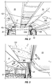
- FIG. 2 shows a perspective view of a portion of a cabin of an aircraft.
- the cabin includes a first projector 100a positioned on a curtain header 40a and a second projector 100b positioned on a curtain header 40b.
- the body of the projectors 100 may be partially hidden, camouflaged, and/or partially obscured on the curtain headers 40 so that substantially only the lens is visible.
- Curtains 30 are connected to the curtain headers 40 and may be used to selectively separate portions of the cabin.
- the projectors 100a and 100b are configured to project an image on an adjacent portion of the ceiling 50 of the cabin.
- projector 100a is projecting an image 150 onto portion 50a adjacent to the projector 100a.
- the image 150 may be a static pattern, static image, or moving image.
- the image 150 may be a pattern of twinkling stars as shown in FIG. 2 .
- the image could be a static or animated illustration of a brand name, logo, or escape route instructions.
- the curtain header 40 may include an exits sign 41 and the ceiling portions 50a and 50b may be separated by an overhead bin 20.
- the projectors 100a and 100b may be operated independently and project different images or one projector 100b may not project an image while an adjacent projector 100a may project an image 150 as shown in FIG. 2 . Images may be adjusted to compensate for elongation or foreshortening based on the curvature of the cabin portion upon which the image is projected in order to provide a clear and undistorted representation.
- FIG. 3 shows a projector 100 projecting an image 150 and an adjacent ceiling portion 50.
- the projector 100 may be positioned on an upper structure of the aircraft cabin, such as header 40, so that the projection of the image 150 is not obstructed by movement of passengers about the cabin.
- FIG. 4 shows a close up view of a projector 100 mounted on a curtain header 40 adjacent an exit sign 41. Alternatively, the projector 100 may be integrated into or within an exit side 41 or other wall or mounted item in the cabin.
- the projector 100 may be a pico-projector or micro-projector to enable the mounting or positioning the projector 100 at various locations within the vehicle.
- a pico-projector or micro-projector may be mounted on an upper portion of a cabin adjacent to the ceiling to permit the projection of an image upon the ceiling.
- the projector 100 may have some or all of the body hidden inside of a structure, such as the curtain header, with only the lens of the projector being visible.
- the projector 100 may have a barrel portion surrounding the projection lens to prevent or reduce shining light into the eyes of passengers or crew who may be standing or walking in an aisle, or a very tall passenger.
- the barrel portion may be long enough to ensure it is not possible to observe the projector light directly, but only view reflected light from a projection surface.
- the projector 100 may have an external adjustment feature for alignment.
- a vehicle such as an aircraft 1, may include a plurality of projectors 100 throughout the vehicle capable of projecting an image on an adjacent portion of the ceiling.
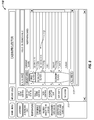
- the operation of the projectors may be controlled at a control panel 110 such as the control panel 110 shown in FIG. 5 .
- the control panel 110 may include an interface 111 that permits the selection of projectors within the vehicle.
- the control panel 110 may include an interface that permits the control of projectors located in various locations within the vehicle. For example, interfaces 112a, 112b, and 112c may permit the operation of projectors within a specified area of the vehicle.
- the control panel 110 may also include an interface 112 to permit the uniform operation of projectors 100 throughout the vehicle.
- the images projected by the projectors 100 may be determined based on settings 113 on the control panel.
- the control panel 110 may be used to change the image between various images, such as, starry skies and northern skies.
- Various themes and configurations may be included on the control panel 110 as would be appreciated by one of ordinary skill in the art having the benefit of this disclosure.
- the layout of the control panel 110 as shown in FIG. 5 is for illustrative purposes and may be varied as would be appreciated by one of ordinary skill in the art having the benefit of this disclosure.
- FIG. 6 shows a schematic of one configuration of a projector 100 having an aperture 103.
- the aperture 103 may be positioned between an image engine 101 and a lens 102 within the projector 100.
- the aperture 103 may aid in blending the edges of the image 150 projected by the projector 100, which may be desired.
- the edges of the images projected by the projector 100 may not be sharp, but rather fuzzy due to the use of the aperture 103.
- the fuzzy edges of adjacent images may permit improved blending of the two images at interfaces such as 100ac or 100bd shown in FIG.
- FIG. 7 shows a schematic of one configuration of a projector 200 having an aperture 203 to aid in the blending of adjacent images as discussed herein.
- the projector 200 includes an image engine 201 and lens 202 with an aperture 203 positioned exterior of the projector 200.
- the projection of the image 250 through an aperture 203 may provide fuzzy edges.
Landscapes
- Engineering & Computer Science (AREA)
- Aviation & Aerospace Engineering (AREA)
- Physics & Mathematics (AREA)
- General Physics & Mathematics (AREA)
- Multimedia (AREA)
- Signal Processing (AREA)
- Projection Apparatus (AREA)
- Transforming Electric Information Into Light Information (AREA)
- Arrangements Of Lighting Devices For Vehicle Interiors, Mounting And Supporting Thereof, Circuits Therefore (AREA)
Abstract
Description
- The examples described herein relate to a method and system of projecting a desired image onto an interior portion of an aircraft. Vehicles, especially mass transit vehicles, may include lighting used to create a theme, mood, or effect during travel. For example, color lights, such as light-emitting diodes (LEDs) may be used to illuminate a portion of the interior with a desired color. For example, an airline may prefer to have the ceiling of an aircraft to be one color during boarding, but a different color during cruising, and maybe even a different color during landing and takeoff procedures. While the use of a number of different LEDs may permit different color schemes in the interior of a vehicle, the LEDs may not permit a wide variation of themes or effects. For example, the lighting only permits the illumination of the cabin in a particular color.
- Present lighting schemes may be limited to the color of LEDs already installed on the vehicle, which may limit the number of different colors to just a few colors due to space constraints. The use of LEDs lighting may require a significant effort if it is desired to change the colors and/or theme that may be displayed within the vehicle especially when requiring an addition of starry skies, shooting stars and/or constellations on the ceiling of a vehicle, such as an aircraft. Present lighting systems do not permit the displaying of a company logo and/or brand. Other drawbacks of current vehicle theme and/or lighting systems may exist.
- The present disclosure is directed to a method and system that overcomes some of the problems and disadvantages discussed above.
- One example supported by the disclosure is a vehicle projection system comprising a first projector positioned adjacent to a first portion of a ceiling of a vehicle, wherein the first projector is configured to project a first image on the first portion of the ceiling. The image may be a moving image. The image may be a starry sky, northern sky, moon, constellation, and/or other natural sky scene. The image may be projected in conjunction with sound from an on board sound system. The projector may be a pico-projector or a micro-projector. The vehicle may be an aircraft having a cabin. The first portion of the ceiling may be positioned between two overhead bins. The first projector may be disposed on an overhead portion of the cabin of an aircraft. The first projector may be disposed on a first curtain header in the cabin of an aircraft.
- The system may comprise a second projector disposed on an overhead portion of the cabin of the aircraft, wherein the second projector is configured to project a second image on a second portion of the ceiling. The second projector may be disposed on a second curtain header in the cabin of the aircraft. The first and second portions of the ceiling may be positioned between the first and second projectors. The first projector may include a first edge fader aperture and the second projector may include a second edge fader aperture, wherein the first and second edge fader apertures blend an interface between the first and second images. The first edge fader aperture may be positioned within the first projector between a first image engine and a first lens and the second edge fader aperture may be positioned within the second projector between a second image engine and a second lens. The system may include a control panel configured to control the projection of the first image by the first projector and the projection of the second image by the second projector. The control panel may be used to control a plurality of projectors within the vehicle.
- Another example supported by the disclosure is a method of creating an image on a portion of a ceiling of a vehicle. The method comprises providing a first projector and projecting a first image from the first projector on a first portion of a ceiling of a vehicle, the first portion of the ceiling being adjacent to the first projector. The method may include controlling the first image projected by the first projector with a control panel. The image may be a moving image. The method may include providing a second projector and projecting a second image from the second projector on a second portion of the ceiling of the vehicle, the second portion of the ceiling being adjacent to the second projector. The method may include blending an interface between the first image and the second image. The method may include positioning the first projection on an overhead portion of a cabin of an aircraft.
-
-
FIG. 1 is a partial top cross-section view of a portion of a vehicle having a plurality of projectors. -
FIG. 2 is a perspective view of a portion of an interior of an aircraft having a projector. -
FIG. 3 is a perspective view of a portion of an interior of an aircraft having a projector. -
FIG. 4 is a perspective view of a portion of an interior of an aircraft having a projector. -
FIG. 5 shows one example of a control panel for controlling a plurality of projectors within an aircraft and options for flight attendants to select one. -
FIG. 6 shows a schematic of one example of a projector with projected scene edge control. -
FIG. 7 shows a schematic of one example of a projector with projected scene edge control. - While the disclosure is susceptible to various modifications and alternative forms, specific examples have been shown in the drawings and will be described in detail herein. However, it should be understood that the disclosure is not intended to be limited to the particular forms disclosed. Rather, the intention is to cover all modifications, equivalents and alternatives falling within the scope of the disclosure as defined by the appended claims.
-
FIG. 1 shows a partial top cross-section view of a portion of a cabin of an aircraft 1. The cabin includesseats 10 andoverhead bins 20. A plurality ofprojectors 100a-d (collectively projectors 100) are positionedadjacent ceiling portions 50a-d betweenoverhead bins 20 above passenger walkways between theseats 10 rows. Theprojectors 100a-d may be mounted on an upper portion of the cabin of the aircraft 1 so that they are positioned above passengers walking through passenger walkways. The location of the projectors above the passengers may be such that a passenger moving about the cabin won't obscure the image projected from aprojector 100. For example,projectors 100 may be mounted or positioned on acurtain header 40 that separate different portions of the aircraft 1.Curtains 30 on thecurtain headers 40a-d (collectively curtain headers 40) may be used as a separation barrier to separate different portions of the aircraft 1. Theprojectors 100a-d are configured to project an image on theceiling portion 50a-d adjacent to theprojectors 100a-d. For example,projector 100a may project an image ontoceiling portion 50a,projector 100b may project an image ontoceiling portion 50b,projector 100c may project an image ontoceiling portion 50c, andprojector 100d may project an image ontoceiling portion 50d. Theprojectors 100 may be a pico-projector or a micro-projector. As used herein, pico-projector or micro-projector means a hand held sized projector or smaller. The image may be projected in conjunction with audio, such as sound, from an onboard sound system. The onboard sound system could be a vehicle sound system and/or a personal sound system of a passenger. - A
control panel 110 may be used to control the operation of theprojectors 100a-d. Thecontrol panel 110 may be a panel mounted on a structure within the cabin of the aircraft 1. Alternatively, thecontrol panel 110 could be a mobile device operated by a member of the flight crew. Thecontrol panel 110 may be used to project the same image on allceiling portions 50 adjacent aprojector 100. Likewise, thecontrol panel 110 may permit projection of different images ondifferent ceiling portions 50. For example, all theprojectors 100 in one area of a vehicle may project a first image and allprojectors 100 in a second area of a vehicle may project a second image. The image may be a static image that is based on a theme, such as starry skies, northern skies, nature scenes, galaxy or space scenes, or various other scenes or images as would be appreciated by one of ordinary skill in the art having the benefit of this disclosure. The images may be a static image or may be a moving image, such as a movie or a moving design such as shooting stars in the midst of starry skies. The configuration ofseats 10,bins 20,curtains 30,curtain headers 40,ceiling portions 50a-d,projectors 100a-d, andcontrol panel 110 shown inFIG. 1 is for illustrative purposes and may be varied as would be appreciated by one of ordinary skill in the art having the benefit of this disclosure. Further, theprojectors 100a-d could be installed in various vehicles, such as a bus, train, ship, or other vehicle to project an image or images onto a portion of a ceiling or other surface as would be appreciated by one of ordinary skill in the art having the benefit of this disclosure. -
FIG. 2 shows a perspective view of a portion of a cabin of an aircraft. The cabin includes afirst projector 100a positioned on acurtain header 40a and asecond projector 100b positioned on acurtain header 40b. The body of theprojectors 100 may be partially hidden, camouflaged, and/or partially obscured on thecurtain headers 40 so that substantially only the lens is visible.Curtains 30 are connected to thecurtain headers 40 and may be used to selectively separate portions of the cabin. Theprojectors ceiling 50 of the cabin. For example,projector 100a is projecting animage 150 ontoportion 50a adjacent to theprojector 100a. Theimage 150 may be a static pattern, static image, or moving image. For example, theimage 150 may be a pattern of twinkling stars as shown inFIG. 2 . Alternatively, the image could be a static or animated illustration of a brand name, logo, or escape route instructions. Thecurtain header 40 may include an exits sign 41 and theceiling portions overhead bin 20. Theprojectors projector 100b may not project an image while anadjacent projector 100a may project animage 150 as shown inFIG. 2 . Images may be adjusted to compensate for elongation or foreshortening based on the curvature of the cabin portion upon which the image is projected in order to provide a clear and undistorted representation. -
FIG. 3 shows aprojector 100 projecting animage 150 and anadjacent ceiling portion 50. Theprojector 100 may be positioned on an upper structure of the aircraft cabin, such asheader 40, so that the projection of theimage 150 is not obstructed by movement of passengers about the cabin.FIG. 4 shows a close up view of aprojector 100 mounted on acurtain header 40 adjacent anexit sign 41. Alternatively, theprojector 100 may be integrated into or within anexit side 41 or other wall or mounted item in the cabin. Theprojector 100 may be a pico-projector or micro-projector to enable the mounting or positioning theprojector 100 at various locations within the vehicle. For example, a pico-projector or micro-projector may be mounted on an upper portion of a cabin adjacent to the ceiling to permit the projection of an image upon the ceiling. Theprojector 100 may have some or all of the body hidden inside of a structure, such as the curtain header, with only the lens of the projector being visible. Theprojector 100 may have a barrel portion surrounding the projection lens to prevent or reduce shining light into the eyes of passengers or crew who may be standing or walking in an aisle, or a very tall passenger. The barrel portion may be long enough to ensure it is not possible to observe the projector light directly, but only view reflected light from a projection surface. Theprojector 100 may have an external adjustment feature for alignment. - A vehicle, such as an aircraft 1, may include a plurality of
projectors 100 throughout the vehicle capable of projecting an image on an adjacent portion of the ceiling. The operation of the projectors may be controlled at acontrol panel 110 such as thecontrol panel 110 shown inFIG. 5 . Thecontrol panel 110 may include aninterface 111 that permits the selection of projectors within the vehicle. Thecontrol panel 110 may include an interface that permits the control of projectors located in various locations within the vehicle. For example,interfaces control panel 110 may also include aninterface 112 to permit the uniform operation ofprojectors 100 throughout the vehicle. The images projected by theprojectors 100 may be determined based onsettings 113 on the control panel. For example, thecontrol panel 110 may be used to change the image between various images, such as, starry skies and northern skies. Various themes and configurations may be included on thecontrol panel 110 as would be appreciated by one of ordinary skill in the art having the benefit of this disclosure. The layout of thecontrol panel 110 as shown inFIG. 5 is for illustrative purposes and may be varied as would be appreciated by one of ordinary skill in the art having the benefit of this disclosure. -
FIG. 6 shows a schematic of one configuration of aprojector 100 having anaperture 103. Theaperture 103 may be positioned between animage engine 101 and alens 102 within theprojector 100. Theaperture 103 may aid in blending the edges of theimage 150 projected by theprojector 100, which may be desired. For example, there may be an interface, such as interface 100ac or 100bd shown inFIG. 1 , between two images projected on adjacent ceiling portions, such asportions portion FIG. 1 . The edges of the images projected by theprojector 100 may not be sharp, but rather fuzzy due to the use of theaperture 103. The fuzzy edges of adjacent images may permit improved blending of the two images at interfaces such as 100ac or 100bd shown inFIG. 1 .FIG. 7 shows a schematic of one configuration of aprojector 200 having anaperture 203 to aid in the blending of adjacent images as discussed herein. Theprojector 200 includes animage engine 201 andlens 202 with anaperture 203 positioned exterior of theprojector 200. The projection of theimage 250 through anaperture 203 may provide fuzzy edges. - Further, the disclosure comprises examples according to the following clauses:
- Clause 1. A vehicle projection system comprising: a first projector (100a) positioned adjacent to a first portion of a ceiling (50a) of a vehicle (1); wherein the first projector (100a) is configured to project a first image (150) on the first portion of the ceiling (50a).
- Clause 2. The system of clause 1, wherein the image (150) is a moving image.
- Clause 3. The system of clause 1, wherein the image (150) is one of a starry sky, northern sky, moon, constellation, or other natural sky scene.
- Clause 4. The system of clause 3, wherein the image (150) is projected in conjunction with sound from an on board sound system.
- Clause 5. The system of clause 1, wherein the projector (150) is one of a pico-projector and a micro-projector.
- Clause 6. The system of clause 1, the vehicle further comprising an aircraft (1) having a cabin.
- Clause 7. The system of clause 6, wherein the first portion of the ceiling (50) is positioned between two overhead bins (20).
- Clause 8. The system of clause 6, wherein the first projector (100) is disposed on an overhead portion (40) of the cabin of the aircraft (1).
- Clause 9. The system of clause 8, wherein the first projector (100a) is disposed on a first curtain header (40) in the cabin.
-
Clause 10. The system of clause 8, further comprising a second projector (100c) disposed on an overhead portion (40c) of the cabin of the aircraft (1), wherein the second projector (100c) is configured to project a second image (150) on a second portion of the ceiling (50c). - Clause 11. The system of
clause 10, wherein the second projector (100c) is disposed on a second curtain header (40c) in the cabin. - Clause 12. The system of
clause 10, wherein the first portion of the ceiling (50a) and the second portion of the ceiling (50c) are positioned between the first and second projectors (100a, 100c). - Clause 13. The system of clause 12, wherein the first projector (100a) includes a first edge fader aperture (103) and the second projector (100c) includes a second edge fader aperture (103), wherein the first and second edge fader apertures (103) blend an interface (100ac) between the first and second images (150).
- Clause 14A. The system of clause 13, wherein the first edge fader aperture (103) is positioned within the first projector (100) between a first image engine (101) and a first lens (102) and the second edge fader aperture (103) is positioned within the second projector (100) between a second image engine (101) and a second lens (102).
- Clause 14B. The system of clause 13, wherein the first projector (200) has a first image engine (201) and a first lens (202) and the first edge fader aperture (203) is positioned exterior of the first projector (200), and wherein the second projector (200) has a second image engine (201) and a second lens (202) and the second edge fader aperture (203) is positioned exterior of the second projector (200).
- Clause 15. The system of
clause 10, further comprising a control panel (110) configured to control the projection of the first image (150) by the first projector (100a) and the projection of the second image (150) by the second projector (100c). - Clause 16. The system of clause 6, wherein the first projector (100) further comprising a plurality of projectors (100a-d) positioned to an adjacent portion of the ceiling (50a-d) of the cabin and wherein each projector (100a-d) is configured to project an image (150) on the adjacent portion of the ceiling (50a-d).
- Clause 17. The system of clause 16, further comprising a control panel (110) configured to control the projection of the image (150) by the plurality of projectors (100a-d).
- Clause 18. A method of creating an image on a portion of a ceiling of a vehicle comprising: providing a first projector (100); and projecting a first image (150) from the first projector (100) on a first portion of a ceiling of a vehicle (50), the first portion of the ceiling (50) being adjacent to the first projector (100).
- Clause 19. The method of clause 18, further comprising controlling the first image (150) projected by the first projector (100) with a control panel (110).
-
Clause 20. The method of clause 18, wherein the image (150) is a moving image. - Clause 21. The method of clause 18, further comprising providing a second projector (100) and projecting a second image (150) from the second projector (100) on a second portion of the ceiling (50) of the vehicle (1), the second portion of the ceiling (50) being adjacent to the second projector (100).
- Clause 22. The method of clause 21, further comprising blending an interface (100ac) between the first image and the second image (150).
- Clause 23. The method of clause 18, wherein providing a first projector (150) further comprises positioning the first projector (150) on an overhead portion (40) of a cabin of an aircraft (1).
- Although this disclosure has been described in terms of certain examples, other examples that are apparent to those of ordinary skill in the art, including examples that do not provide all of the features and advantages set forth herein, are also within the scope of this disclosure. Accordingly, the scope of the present disclosure is defined only by reference to the appended claims and equivalents thereof.
Claims (15)
- A vehicle projection system comprising:a first projector (100a) positioned adjacent to a first portion of a ceiling (50a) of a vehicle (1);wherein the first projector (100a) is configured to project a first image (150) on the first portion of the ceiling (50a).
- The system of claim 1, wherein the image (150) is at least one of:a moving image; anda starry sky, northern sky, moon, constellation, or other natural sky scene.
- The system of claim 1 or 2, wherein the image (150) is projected in conjunction with sound from an on board sound system.
- The system of any one of the preceding claims, wherein the first projector (100) is one of a pico-projector and a micro-projector.
- The system of any one of the preceding claims, the vehicle further comprising an aircraft (1) having a cabin.
- The system of claim 5, wherein the first portion of the ceiling (50) is positioned between two overhead bins (20).
- The system of claim 5 or 6, wherein the first projector (100) is disposed on one of:an overhead portion (40) of the cabin of the aircraft (1); anda first curtain header (40) in the cabin.
- The system of any one of claims 5-7, further comprising a second projector (100c) disposed on an overhead portion (40c) of the cabin of the aircraft (1), wherein the second projector (100c) is configured to project a second image (150) on a second portion of the ceiling (50c), wherein the second projector (100c) is disposed on a second curtain header (40c) in the cabin, wherein the first portion of the ceiling (50a) and the second portion of the ceiling (50c) are positioned between the first and second projectors (100a, 100c).
- The system of claim 8, the first projector (100a) includes a first edge fader aperture (103) and the second projector (100c) includes a second edge fader aperture (103), wherein the first and second edge fader apertures (103) blend an interface (100ac) between the first and second images (150), the first edge fader aperture (103) is positioned within the first projector (100) between a first image engine (101) and a first lens (102) and the second edge fader aperture (103) is positioned within the second projector (100) between a second image engine (101) and a second lens (102).
- The system of claim 8 or 9, further comprising a control panel (110) configured to control the projection of the first image (150) by the first projector (100a) and the projection of the second image (150) by the second projector (100c).
- The system of any one of claims 5-10, wherein the first projector (100) further comprises:a plurality of projectors (100a-d) positioned to an adjacent portion of the ceiling (50a-d) of the cabin and wherein each projector (100a-d) is configured to project an image (150) on the adjacent portion of the ceiling (50a-d); andwherein the system further comprises a control panel (110) configured to control the projection of the image (150) by the plurality of projectors (100a-d).
- A method of creating an image on a portion of a ceiling of a vehicle comprising:providing a first projector (100); andprojecting a first image (150) from the first projector (100) on a first portion of a ceiling of a vehicle (50), the first portion of the ceiling (50) being adjacent to the first projector (100),wherein providing a first projector (100) further comprises positioning the first projector (100) on an overhead portion (40) of a cabin of an aircraft (1).
- The method of claim 12, further comprising at least one of:controlling the first image (150) projected by the first projector (100) with a control panel (110); andproviding a second projector (100) and projecting a second image (150) from the second projector (100) on a second portion of the ceiling (50) of the vehicle (1), the second portion of the ceiling (50) being adjacent to the second projector (100).
- The method of claim 13, further comprising blending an interface (100ac) between the first image and the second image (150).
- The method of any one of claims 12-14, wherein the image (150) is a moving image.
Applications Claiming Priority (1)
| Application Number | Priority Date | Filing Date | Title |
|---|---|---|---|
| US14/645,101 US9731824B2 (en) | 2015-03-11 | 2015-03-11 | Unique system and method of creating scenes within a moving vehicle such as an aircraft |
Publications (2)
| Publication Number | Publication Date |
|---|---|
| EP3068133A1 true EP3068133A1 (en) | 2016-09-14 |
| EP3068133B1 EP3068133B1 (en) | 2022-01-05 |
Family
ID=55963125
Family Applications (1)
| Application Number | Title | Priority Date | Filing Date |
|---|---|---|---|
| EP16159816.4A Active EP3068133B1 (en) | 2015-03-11 | 2016-03-11 | Unique system and method of creating scenes within a moving vehicle such as an aircraft |
Country Status (2)
| Country | Link |
|---|---|
| US (1) | US9731824B2 (en) |
| EP (1) | EP3068133B1 (en) |
Cited By (4)
| Publication number | Priority date | Publication date | Assignee | Title |
|---|---|---|---|---|
| EP3524505A1 (en) * | 2018-02-13 | 2019-08-14 | Chantiers de l'Atlantique | Vessel comprising a living space with means for image projection |
| CN111516880A (en) * | 2020-05-29 | 2020-08-11 | 中国商用飞机有限责任公司 | Cabin partition device, operation method thereof and airplane provided with cabin partition device |
| US20250115358A1 (en) * | 2023-10-09 | 2025-04-10 | B/E Aerospace, Inc. | Cockpit secondary barrier |
| US12616762B2 (en) | 2021-01-05 | 2026-05-05 | The Boeing Company | Ultraviolet device and methods of using the same |
Families Citing this family (16)
| Publication number | Priority date | Publication date | Assignee | Title |
|---|---|---|---|---|
| US10214287B2 (en) * | 2016-02-26 | 2019-02-26 | The Boeing Company | Vehicle cabin wayfinding assembly |
| US10303414B2 (en) | 2016-07-15 | 2019-05-28 | Panasonic Intellectual Property Management Co., Ltd. | Device, system, and method of controlling projection image |
| US10556685B2 (en) * | 2017-05-30 | 2020-02-11 | The Boeing Company | Header assembly and method therefore |
| DE102018000216B4 (en) * | 2018-01-12 | 2023-02-02 | Diehl Aerospace Gmbh | Display structure for a passenger cabin of an aircraft and method for operating the display structure |
| DE102018010242B4 (en) | 2018-02-10 | 2022-02-03 | Diehl Aerospace Gmbh | Retrofit method for a projection module |
| DE102018001100B4 (en) * | 2018-02-10 | 2021-02-25 | Diehl Aerospace Gmbh | Projection module, passenger cabin and retrofit procedures |
| US10365546B1 (en) | 2018-04-16 | 2019-07-30 | The Boeing Company | Vehicle projection system and method of using |
| DE102018004829A1 (en) * | 2018-06-15 | 2019-12-19 | Diehl Aerospace Gmbh | Determination of predistortion data for a projection and projector module |
| US10652974B2 (en) * | 2018-07-20 | 2020-05-12 | The Boeing Company | Fiber optic twinkling star patterns by means of light engine and specialized optics |
| US11034429B2 (en) * | 2018-08-24 | 2021-06-15 | The Boeing Company | Ceiling header system for aircraft cabin |
| DE102018130569B4 (en) * | 2018-11-30 | 2021-04-29 | Airbus Operations Gmbh | System and method for displaying a full-scale cabin layout |
| US10696404B1 (en) | 2019-01-21 | 2020-06-30 | Boeing Company, The | Application of artificial intelligence to implement augmented reality, virtual reality, and mixed reality to enhance passenger experience to flying with mood lighting |
| CN112462566A (en) * | 2020-11-13 | 2021-03-09 | 广州小鹏汽车科技有限公司 | Vehicle-mounted cinema system control method, vehicle-mounted cinema system, vehicle and storage medium |
| GB2624634B (en) * | 2022-11-22 | 2025-05-07 | Bayerische Motoren Werke Ag | Integration of Projector |
| DE102023108395A1 (en) | 2023-04-03 | 2024-10-10 | Bayerische Motoren Werke Aktiengesellschaft | Device for interior lighting of a motor vehicle |
| US12043171B1 (en) | 2023-05-12 | 2024-07-23 | The Boeing Company | Invisible lighted feature through a composite panel |
Citations (5)
| Publication number | Priority date | Publication date | Assignee | Title |
|---|---|---|---|---|
| WO1995025292A1 (en) * | 1994-03-17 | 1995-09-21 | Thomson Training & Simulation Limited | Edge-blending of projected images |
| JP2004312480A (en) * | 2003-04-09 | 2004-11-04 | Mitsubishi Electric System & Service Co Ltd | Video image projection system |
| US20100201951A1 (en) * | 2009-02-09 | 2010-08-12 | Airbus Operations Gmbh | Image generating illumination of interior surfaces of aircraft |
| US20110095911A1 (en) * | 2007-05-16 | 2011-04-28 | Airbus Sas | Projection Of Different Image Contents In A Large-Capacity Cabin Of A Transport Means |
| US20130235351A1 (en) * | 2012-03-07 | 2013-09-12 | GM Global Technology Operations LLC | Virtual convertible tops, sunroofs, and back windows, and systems and methods for providing same |
Family Cites Families (4)
| Publication number | Priority date | Publication date | Assignee | Title |
|---|---|---|---|---|
| CA1275003A (en) * | 1986-08-08 | 1990-10-09 | F. David E. Corley | Soft edge mask |
| US5959717A (en) * | 1997-12-12 | 1999-09-28 | Chaum; Jerry | Motion picture copy prevention, monitoring, and interactivity system |
| JP2002116500A (en) * | 2000-10-05 | 2002-04-19 | Olympus Optical Co Ltd | Image projection/display device |
| US9158185B2 (en) * | 2013-01-07 | 2015-10-13 | Lumexis Corporation | Personal interactive overhead projection inflight entertainment system |
-
2015
- 2015-03-11 US US14/645,101 patent/US9731824B2/en active Active
-
2016
- 2016-03-11 EP EP16159816.4A patent/EP3068133B1/en active Active
Patent Citations (5)
| Publication number | Priority date | Publication date | Assignee | Title |
|---|---|---|---|---|
| WO1995025292A1 (en) * | 1994-03-17 | 1995-09-21 | Thomson Training & Simulation Limited | Edge-blending of projected images |
| JP2004312480A (en) * | 2003-04-09 | 2004-11-04 | Mitsubishi Electric System & Service Co Ltd | Video image projection system |
| US20110095911A1 (en) * | 2007-05-16 | 2011-04-28 | Airbus Sas | Projection Of Different Image Contents In A Large-Capacity Cabin Of A Transport Means |
| US20100201951A1 (en) * | 2009-02-09 | 2010-08-12 | Airbus Operations Gmbh | Image generating illumination of interior surfaces of aircraft |
| US20130235351A1 (en) * | 2012-03-07 | 2013-09-12 | GM Global Technology Operations LLC | Virtual convertible tops, sunroofs, and back windows, and systems and methods for providing same |
Cited By (7)
| Publication number | Priority date | Publication date | Assignee | Title |
|---|---|---|---|---|
| EP3524505A1 (en) * | 2018-02-13 | 2019-08-14 | Chantiers de l'Atlantique | Vessel comprising a living space with means for image projection |
| FR3077797A1 (en) * | 2018-02-13 | 2019-08-16 | Stx France S.A. | SHIP COMPRISING A PLACE OF LIFE WITH MEANS FOR PROJECTING IMAGES |
| CN110155255A (en) * | 2018-02-13 | 2019-08-23 | 大西洋造船厂 | boat including living space with image projection device |
| CN111516880A (en) * | 2020-05-29 | 2020-08-11 | 中国商用飞机有限责任公司 | Cabin partition device, operation method thereof and airplane provided with cabin partition device |
| CN111516880B (en) * | 2020-05-29 | 2021-11-23 | 中国商用飞机有限责任公司 | Cabin partition device, operation method thereof and airplane provided with cabin partition device |
| US12616762B2 (en) | 2021-01-05 | 2026-05-05 | The Boeing Company | Ultraviolet device and methods of using the same |
| US20250115358A1 (en) * | 2023-10-09 | 2025-04-10 | B/E Aerospace, Inc. | Cockpit secondary barrier |
Also Published As
| Publication number | Publication date |
|---|---|
| US9731824B2 (en) | 2017-08-15 |
| EP3068133B1 (en) | 2022-01-05 |
| US20160264243A1 (en) | 2016-09-15 |
Similar Documents
| Publication | Publication Date | Title |
|---|---|---|
| EP3068133B1 (en) | Unique system and method of creating scenes within a moving vehicle such as an aircraft | |
| US9499270B2 (en) | Supply module for passenger transport vehicles | |
| US10414499B2 (en) | Passenger service unit and related systems | |
| US7455263B2 (en) | Airplane interior systems | |
| US8556478B2 (en) | Illumination device for several people in airplanes | |
| US8461505B2 (en) | Systems and methods for interior surfaces image illumination having dual projector | |
| RU2354586C1 (en) | Long-haul airplane | |
| US9701411B2 (en) | Evacuation slide with a guidance marking | |
| EP2815973A1 (en) | Virtual star illumination in a cabin of an aircraft | |
| EP3213996A1 (en) | Aircraft mounted display module | |
| US9688406B2 (en) | Interior component for a vehicle with a modular passenger service unit | |
| US20240359823A1 (en) | Methods and systems for lighting a vertical take-off and landing vehicle | |
| CN110736042B (en) | Optical fiber scintillation star pattern with light engine and dedicated optics | |
| CN110300707A (en) | A device for projecting the outer surface of an aircraft | |
| EP3210887B1 (en) | Vehicle cabin wayfinding assembly | |
| CA3060296C (en) | Application of artificial intelligence to implement augmented reality, virtual reality, and mixed reality to enhance passenger experience to flying with mood lighting | |
| EP3702002A1 (en) | Passenger service unit with cover | |
| US10365546B1 (en) | Vehicle projection system and method of using |
Legal Events
| Date | Code | Title | Description |
|---|---|---|---|
| PUAI | Public reference made under article 153(3) epc to a published international application that has entered the european phase |
Free format text: ORIGINAL CODE: 0009012 |
|
| 17P | Request for examination filed |
Effective date: 20160311 |
|
| AK | Designated contracting states |
Kind code of ref document: A1 Designated state(s): AL AT BE BG CH CY CZ DE DK EE ES FI FR GB GR HR HU IE IS IT LI LT LU LV MC MK MT NL NO PL PT RO RS SE SI SK SM TR |
|
| AX | Request for extension of the european patent |
Extension state: BA ME |
|
| STAA | Information on the status of an ep patent application or granted ep patent |
Free format text: STATUS: EXAMINATION IS IN PROGRESS |
|
| 17Q | First examination report despatched |
Effective date: 20180918 |
|
| GRAP | Despatch of communication of intention to grant a patent |
Free format text: ORIGINAL CODE: EPIDOSNIGR1 |
|
| STAA | Information on the status of an ep patent application or granted ep patent |
Free format text: STATUS: GRANT OF PATENT IS INTENDED |
|
| RIC1 | Information provided on ipc code assigned before grant |
Ipc: H04N 9/31 20060101AFI20201218BHEP |
|
| INTG | Intention to grant announced |
Effective date: 20210126 |
|
| GRAJ | Information related to disapproval of communication of intention to grant by the applicant or resumption of examination proceedings by the epo deleted |
Free format text: ORIGINAL CODE: EPIDOSDIGR1 |
|
| STAA | Information on the status of an ep patent application or granted ep patent |
Free format text: STATUS: EXAMINATION IS IN PROGRESS |
|
| INTC | Intention to grant announced (deleted) | ||
| GRAP | Despatch of communication of intention to grant a patent |
Free format text: ORIGINAL CODE: EPIDOSNIGR1 |
|
| STAA | Information on the status of an ep patent application or granted ep patent |
Free format text: STATUS: GRANT OF PATENT IS INTENDED |
|
| INTG | Intention to grant announced |
Effective date: 20210719 |
|
| GRAS | Grant fee paid |
Free format text: ORIGINAL CODE: EPIDOSNIGR3 |
|
| GRAA | (expected) grant |
Free format text: ORIGINAL CODE: 0009210 |
|
| STAA | Information on the status of an ep patent application or granted ep patent |
Free format text: STATUS: THE PATENT HAS BEEN GRANTED |
|
| AK | Designated contracting states |
Kind code of ref document: B1 Designated state(s): AL AT BE BG CH CY CZ DE DK EE ES FI FR GB GR HR HU IE IS IT LI LT LU LV MC MK MT NL NO PL PT RO RS SE SI SK SM TR |
|
| REG | Reference to a national code |
Ref country code: GB Ref legal event code: FG4D |
|
| REG | Reference to a national code |
Ref country code: CH Ref legal event code: EP |
|
| REG | Reference to a national code |
Ref country code: AT Ref legal event code: REF Ref document number: 1461630 Country of ref document: AT Kind code of ref document: T Effective date: 20220115 |
|
| REG | Reference to a national code |
Ref country code: DE Ref legal event code: R096 Ref document number: 602016068001 Country of ref document: DE |
|
| REG | Reference to a national code |
Ref country code: IE Ref legal event code: FG4D |
|
| REG | Reference to a national code |
Ref country code: LT Ref legal event code: MG9D |
|
| REG | Reference to a national code |
Ref country code: NL Ref legal event code: MP Effective date: 20220105 |
|
| REG | Reference to a national code |
Ref country code: AT Ref legal event code: MK05 Ref document number: 1461630 Country of ref document: AT Kind code of ref document: T Effective date: 20220105 |
|
| PG25 | Lapsed in a contracting state [announced via postgrant information from national office to epo] |
Ref country code: NL Free format text: LAPSE BECAUSE OF FAILURE TO SUBMIT A TRANSLATION OF THE DESCRIPTION OR TO PAY THE FEE WITHIN THE PRESCRIBED TIME-LIMIT Effective date: 20220105 |
|
| PG25 | Lapsed in a contracting state [announced via postgrant information from national office to epo] |
Ref country code: SE Free format text: LAPSE BECAUSE OF FAILURE TO SUBMIT A TRANSLATION OF THE DESCRIPTION OR TO PAY THE FEE WITHIN THE PRESCRIBED TIME-LIMIT Effective date: 20220105 Ref country code: RS Free format text: LAPSE BECAUSE OF FAILURE TO SUBMIT A TRANSLATION OF THE DESCRIPTION OR TO PAY THE FEE WITHIN THE PRESCRIBED TIME-LIMIT Effective date: 20220105 Ref country code: PT Free format text: LAPSE BECAUSE OF FAILURE TO SUBMIT A TRANSLATION OF THE DESCRIPTION OR TO PAY THE FEE WITHIN THE PRESCRIBED TIME-LIMIT Effective date: 20220505 Ref country code: NO Free format text: LAPSE BECAUSE OF FAILURE TO SUBMIT A TRANSLATION OF THE DESCRIPTION OR TO PAY THE FEE WITHIN THE PRESCRIBED TIME-LIMIT Effective date: 20220405 Ref country code: LT Free format text: LAPSE BECAUSE OF FAILURE TO SUBMIT A TRANSLATION OF THE DESCRIPTION OR TO PAY THE FEE WITHIN THE PRESCRIBED TIME-LIMIT Effective date: 20220105 Ref country code: HR Free format text: LAPSE BECAUSE OF FAILURE TO SUBMIT A TRANSLATION OF THE DESCRIPTION OR TO PAY THE FEE WITHIN THE PRESCRIBED TIME-LIMIT Effective date: 20220105 Ref country code: ES Free format text: LAPSE BECAUSE OF FAILURE TO SUBMIT A TRANSLATION OF THE DESCRIPTION OR TO PAY THE FEE WITHIN THE PRESCRIBED TIME-LIMIT Effective date: 20220105 Ref country code: BG Free format text: LAPSE BECAUSE OF FAILURE TO SUBMIT A TRANSLATION OF THE DESCRIPTION OR TO PAY THE FEE WITHIN THE PRESCRIBED TIME-LIMIT Effective date: 20220405 |
|
| PG25 | Lapsed in a contracting state [announced via postgrant information from national office to epo] |
Ref country code: PL Free format text: LAPSE BECAUSE OF FAILURE TO SUBMIT A TRANSLATION OF THE DESCRIPTION OR TO PAY THE FEE WITHIN THE PRESCRIBED TIME-LIMIT Effective date: 20220105 Ref country code: LV Free format text: LAPSE BECAUSE OF FAILURE TO SUBMIT A TRANSLATION OF THE DESCRIPTION OR TO PAY THE FEE WITHIN THE PRESCRIBED TIME-LIMIT Effective date: 20220105 Ref country code: GR Free format text: LAPSE BECAUSE OF FAILURE TO SUBMIT A TRANSLATION OF THE DESCRIPTION OR TO PAY THE FEE WITHIN THE PRESCRIBED TIME-LIMIT Effective date: 20220406 Ref country code: FI Free format text: LAPSE BECAUSE OF FAILURE TO SUBMIT A TRANSLATION OF THE DESCRIPTION OR TO PAY THE FEE WITHIN THE PRESCRIBED TIME-LIMIT Effective date: 20220105 Ref country code: AT Free format text: LAPSE BECAUSE OF FAILURE TO SUBMIT A TRANSLATION OF THE DESCRIPTION OR TO PAY THE FEE WITHIN THE PRESCRIBED TIME-LIMIT Effective date: 20220105 |
|
| PG25 | Lapsed in a contracting state [announced via postgrant information from national office to epo] |
Ref country code: IS Free format text: LAPSE BECAUSE OF FAILURE TO SUBMIT A TRANSLATION OF THE DESCRIPTION OR TO PAY THE FEE WITHIN THE PRESCRIBED TIME-LIMIT Effective date: 20220505 |
|
| REG | Reference to a national code |
Ref country code: DE Ref legal event code: R097 Ref document number: 602016068001 Country of ref document: DE |
|
| PG25 | Lapsed in a contracting state [announced via postgrant information from national office to epo] |
Ref country code: SM Free format text: LAPSE BECAUSE OF FAILURE TO SUBMIT A TRANSLATION OF THE DESCRIPTION OR TO PAY THE FEE WITHIN THE PRESCRIBED TIME-LIMIT Effective date: 20220105 Ref country code: SK Free format text: LAPSE BECAUSE OF FAILURE TO SUBMIT A TRANSLATION OF THE DESCRIPTION OR TO PAY THE FEE WITHIN THE PRESCRIBED TIME-LIMIT Effective date: 20220105 Ref country code: RO Free format text: LAPSE BECAUSE OF FAILURE TO SUBMIT A TRANSLATION OF THE DESCRIPTION OR TO PAY THE FEE WITHIN THE PRESCRIBED TIME-LIMIT Effective date: 20220105 Ref country code: MC Free format text: LAPSE BECAUSE OF FAILURE TO SUBMIT A TRANSLATION OF THE DESCRIPTION OR TO PAY THE FEE WITHIN THE PRESCRIBED TIME-LIMIT Effective date: 20220105 Ref country code: EE Free format text: LAPSE BECAUSE OF FAILURE TO SUBMIT A TRANSLATION OF THE DESCRIPTION OR TO PAY THE FEE WITHIN THE PRESCRIBED TIME-LIMIT Effective date: 20220105 Ref country code: DK Free format text: LAPSE BECAUSE OF FAILURE TO SUBMIT A TRANSLATION OF THE DESCRIPTION OR TO PAY THE FEE WITHIN THE PRESCRIBED TIME-LIMIT Effective date: 20220105 Ref country code: CZ Free format text: LAPSE BECAUSE OF FAILURE TO SUBMIT A TRANSLATION OF THE DESCRIPTION OR TO PAY THE FEE WITHIN THE PRESCRIBED TIME-LIMIT Effective date: 20220105 |
|
| REG | Reference to a national code |
Ref country code: CH Ref legal event code: PL |
|
| PLBE | No opposition filed within time limit |
Free format text: ORIGINAL CODE: 0009261 |
|
| STAA | Information on the status of an ep patent application or granted ep patent |
Free format text: STATUS: NO OPPOSITION FILED WITHIN TIME LIMIT |
|
| PG25 | Lapsed in a contracting state [announced via postgrant information from national office to epo] |
Ref country code: AL Free format text: LAPSE BECAUSE OF FAILURE TO SUBMIT A TRANSLATION OF THE DESCRIPTION OR TO PAY THE FEE WITHIN THE PRESCRIBED TIME-LIMIT Effective date: 20220105 |
|
| REG | Reference to a national code |
Ref country code: BE Ref legal event code: MM Effective date: 20220331 |
|
| 26N | No opposition filed |
Effective date: 20221006 |
|
| PG25 | Lapsed in a contracting state [announced via postgrant information from national office to epo] |
Ref country code: LU Free format text: LAPSE BECAUSE OF NON-PAYMENT OF DUE FEES Effective date: 20220311 Ref country code: LI Free format text: LAPSE BECAUSE OF NON-PAYMENT OF DUE FEES Effective date: 20220331 Ref country code: IE Free format text: LAPSE BECAUSE OF NON-PAYMENT OF DUE FEES Effective date: 20220311 Ref country code: CH Free format text: LAPSE BECAUSE OF NON-PAYMENT OF DUE FEES Effective date: 20220331 |
|
| PG25 | Lapsed in a contracting state [announced via postgrant information from national office to epo] |
Ref country code: SI Free format text: LAPSE BECAUSE OF FAILURE TO SUBMIT A TRANSLATION OF THE DESCRIPTION OR TO PAY THE FEE WITHIN THE PRESCRIBED TIME-LIMIT Effective date: 20220105 Ref country code: BE Free format text: LAPSE BECAUSE OF NON-PAYMENT OF DUE FEES Effective date: 20220331 |
|
| P01 | Opt-out of the competence of the unified patent court (upc) registered |
Effective date: 20230516 |
|
| PG25 | Lapsed in a contracting state [announced via postgrant information from national office to epo] |
Ref country code: IT Free format text: LAPSE BECAUSE OF FAILURE TO SUBMIT A TRANSLATION OF THE DESCRIPTION OR TO PAY THE FEE WITHIN THE PRESCRIBED TIME-LIMIT Effective date: 20220105 |
|
| PG25 | Lapsed in a contracting state [announced via postgrant information from national office to epo] |
Ref country code: HU Free format text: LAPSE BECAUSE OF FAILURE TO SUBMIT A TRANSLATION OF THE DESCRIPTION OR TO PAY THE FEE WITHIN THE PRESCRIBED TIME-LIMIT; INVALID AB INITIO Effective date: 20160311 |
|
| PG25 | Lapsed in a contracting state [announced via postgrant information from national office to epo] |
Ref country code: MK Free format text: LAPSE BECAUSE OF FAILURE TO SUBMIT A TRANSLATION OF THE DESCRIPTION OR TO PAY THE FEE WITHIN THE PRESCRIBED TIME-LIMIT Effective date: 20220105 Ref country code: CY Free format text: LAPSE BECAUSE OF FAILURE TO SUBMIT A TRANSLATION OF THE DESCRIPTION OR TO PAY THE FEE WITHIN THE PRESCRIBED TIME-LIMIT Effective date: 20220105 |
|
| PG25 | Lapsed in a contracting state [announced via postgrant information from national office to epo] |
Ref country code: MT Free format text: LAPSE BECAUSE OF FAILURE TO SUBMIT A TRANSLATION OF THE DESCRIPTION OR TO PAY THE FEE WITHIN THE PRESCRIBED TIME-LIMIT Effective date: 20220105 |
|
| PG25 | Lapsed in a contracting state [announced via postgrant information from national office to epo] |
Ref country code: TR Free format text: LAPSE BECAUSE OF FAILURE TO SUBMIT A TRANSLATION OF THE DESCRIPTION OR TO PAY THE FEE WITHIN THE PRESCRIBED TIME-LIMIT Effective date: 20220105 |
|
| PGFP | Annual fee paid to national office [announced via postgrant information from national office to epo] |
Ref country code: GB Payment date: 20260327 Year of fee payment: 11 |
|
| PGFP | Annual fee paid to national office [announced via postgrant information from national office to epo] |
Ref country code: DE Payment date: 20260327 Year of fee payment: 11 |
|
| PGFP | Annual fee paid to national office [announced via postgrant information from national office to epo] |
Ref country code: FR Payment date: 20260325 Year of fee payment: 11 |