EP3067999A1 - Laser-oscillation cooling device - Google Patents
Laser-oscillation cooling device Download PDFInfo
- Publication number
- EP3067999A1 EP3067999A1 EP15765048.2A EP15765048A EP3067999A1 EP 3067999 A1 EP3067999 A1 EP 3067999A1 EP 15765048 A EP15765048 A EP 15765048A EP 3067999 A1 EP3067999 A1 EP 3067999A1
- Authority
- EP
- European Patent Office
- Prior art keywords
- cryogenic liquid
- laser
- laser excitation
- unit
- excitation unit
- Prior art date
- Legal status (The legal status is an assumption and is not a legal conclusion. Google has not performed a legal analysis and makes no representation as to the accuracy of the status listed.)
- Granted
Links
Images

Classifications
-
- H—ELECTRICITY
- H01—ELECTRIC ELEMENTS
- H01S—DEVICES USING THE PROCESS OF LIGHT AMPLIFICATION BY STIMULATED EMISSION OF RADIATION [LASER] TO AMPLIFY OR GENERATE LIGHT; DEVICES USING STIMULATED EMISSION OF ELECTROMAGNETIC RADIATION IN WAVE RANGES OTHER THAN OPTICAL
- H01S3/00—Lasers, i.e. devices using stimulated emission of electromagnetic radiation in the infrared, visible or ultraviolet wave range
- H01S3/02—Constructional details
- H01S3/04—Arrangements for thermal management
- H01S3/0407—Liquid cooling, e.g. by water
-
- H—ELECTRICITY
- H01—ELECTRIC ELEMENTS
- H01S—DEVICES USING THE PROCESS OF LIGHT AMPLIFICATION BY STIMULATED EMISSION OF RADIATION [LASER] TO AMPLIFY OR GENERATE LIGHT; DEVICES USING STIMULATED EMISSION OF ELECTROMAGNETIC RADIATION IN WAVE RANGES OTHER THAN OPTICAL
- H01S3/00—Lasers, i.e. devices using stimulated emission of electromagnetic radiation in the infrared, visible or ultraviolet wave range
- H01S3/02—Constructional details
- H01S3/04—Arrangements for thermal management
-
- H—ELECTRICITY
- H01—ELECTRIC ELEMENTS
- H01S—DEVICES USING THE PROCESS OF LIGHT AMPLIFICATION BY STIMULATED EMISSION OF RADIATION [LASER] TO AMPLIFY OR GENERATE LIGHT; DEVICES USING STIMULATED EMISSION OF ELECTROMAGNETIC RADIATION IN WAVE RANGES OTHER THAN OPTICAL
- H01S3/00—Lasers, i.e. devices using stimulated emission of electromagnetic radiation in the infrared, visible or ultraviolet wave range
- H01S3/02—Constructional details
- H01S3/04—Arrangements for thermal management
- H01S3/042—Arrangements for thermal management for solid state lasers
-
- H—ELECTRICITY
- H01—ELECTRIC ELEMENTS
- H01S—DEVICES USING THE PROCESS OF LIGHT AMPLIFICATION BY STIMULATED EMISSION OF RADIATION [LASER] TO AMPLIFY OR GENERATE LIGHT; DEVICES USING STIMULATED EMISSION OF ELECTROMAGNETIC RADIATION IN WAVE RANGES OTHER THAN OPTICAL
- H01S5/00—Semiconductor lasers
- H01S5/02—Structural details or components not essential to laser action
- H01S5/024—Arrangements for thermal management
-
- H—ELECTRICITY
- H01—ELECTRIC ELEMENTS
- H01S—DEVICES USING THE PROCESS OF LIGHT AMPLIFICATION BY STIMULATED EMISSION OF RADIATION [LASER] TO AMPLIFY OR GENERATE LIGHT; DEVICES USING STIMULATED EMISSION OF ELECTROMAGNETIC RADIATION IN WAVE RANGES OTHER THAN OPTICAL
- H01S5/00—Semiconductor lasers
- H01S5/02—Structural details or components not essential to laser action
- H01S5/024—Arrangements for thermal management
- H01S5/02407—Active cooling, e.g. the laser temperature is controlled by a thermo-electric cooler or water cooling
- H01S5/02423—Liquid cooling, e.g. a liquid cools a mount of the laser
-
- H—ELECTRICITY
- H10—SEMICONDUCTOR DEVICES; ELECTRIC SOLID-STATE DEVICES NOT OTHERWISE PROVIDED FOR
- H10W—GENERIC PACKAGES, INTERCONNECTIONS, CONNECTORS OR OTHER CONSTRUCTIONAL DETAILS OF DEVICES COVERED BY CLASS H10
- H10W40/00—Arrangements for thermal protection or thermal control
- H10W40/70—Fillings or auxiliary members in containers or in encapsulations for thermal protection or control
- H10W40/73—Fillings or auxiliary members in containers or in encapsulations for thermal protection or control for cooling by change of state
Definitions
- the controller 14 adjusts the degree of opening of the pressure control valve 13 on the basis of a pressure value in the cryostat 2 which is measured by the pressure gauge 12. When it is detected that the pressure in the cryostat 2 is greater than 0.3 MPa on the basis of the measured value of the pressure gauge 12, the controller 14 adjusts the degree of opening of the pressure control valve 12 to increase the degree of opening.
- gas gas including an evaporated component of the cryogenic liquid L and air as major components
- the pressure in the cryostat 2 is lowered to an appropriate value (substantially 0.3 MPa).
- cryogenic liquid L liquid nitrogen is exemplified in this embodiment.
- the kind of the cryogenic liquid L is not limited to the liquid nitrogen, but any one can be selected and used from a group of liquid-phase inert elements such as liquid helium and liquid neon.
- the decompression and return unit 6 connects the cryostat 2 to the storage tank 3.
- the decompression and return unit 6 includes a pipe line 61 connecting the second liquid storage bath 25 in the cryostat 2 to the storage tank 3 and a decompression valve 62 disposed in the middle of the pipe line 61.
- the pressurization pump 53 is a known liquid pump that feeds a liquid along the pipe line 52 by pressurizing the liquid passing therein. That is, the cryogenic liquid L is fed in a direction from the storage tank 3 to the spray nozzle 51 along the pipe line 52 by the pressurization pump 53.
- the laser excitation unit 21 is irradiated with the laser beam Z from a light source which is not illustrated.
- the laser beam Z is excited by the excitation medium in the laser excitation unit 21 and is irradiated toward the outside from the laser excitation unit 21.
- the laser excitation unit 21 locally emits heat by irradiation with the laser beam Z. Specifically, the amount of heat emitted reaches 0.25 KW per square centimeter. Accordingly, the laser excitation unit 21 needs to be cooled via the cooling and support unit 22.
- the flow rate adjusting valve 71 is first opened to supply the cryogenic liquid L from the cylinder 4 to the storage tank 3.
- the pressurization pump 53 is driven.
- the laser excitation unit 21 is continuously cooled.
- the amount of cryogenic liquid L stored in the first liquid storage bath 24 gradually increases.
- the liquid level of the cryogenic liquid L stored in the first liquid storage bath 24 reaches a dimension to which the partition wall 23 extends.
- the liquid level of the cryogenic liquid L exceeds the partition wall 23.
- the cryogenic liquid L flows over the first liquid storage bath 24 and flows to the second liquid storage bath 25 adjacent thereto. Thereafter, the cryogenic liquid L is stored in the second liquid storage bath 25.
- the decompression valve 62 is opened. That is, until a predetermined amount of cryogenic liquid L is stored in the second liquid storage bath 25, the decompression valve 62 is not opened.
- the amount of cryogenic liquid L stored is small and the decompression valve 62 is opened, a sufficient flow rate is not achieved and a possibility exists that gas in the cryostat 2 may be involved with the flow of the cryogenic liquid.
- the cryogenic liquid L passing through the decompression valve 62 flows to the storage tank 3. That is, the cryogenic liquid L supplied from the storage tank 3 via the spray nozzle 51 is returned to the storage tank 3 by the decompression and return unit 6.
- the decompression and return unit 6 includes the decompression valve 62 that decompresses the cryogenic liquid L. According to this constitution, it is possible to sufficiently decompress the cryogenic liquid L by causing the cryogenic liquid L to pass through the decompression valve 62 and to simply constitute the decompression and return unit 6.
- the pressurization and supply unit 50 is provided with the spray nozzle 51 that sprays the cryogenic liquid L onto the laser excitation unit 21. According to this constitution, since the cryogenic liquid L can be supplied to the laser excitation unit 21 at a higher flow speed by spraying the cryogenic liquid L from the spray nozzle 51, it is possible to more effectively cool the laser excitation unit 21.
- the micro-channel 54 has such a size which covers the entire surface of the cooling and support unit 22. Accordingly, the cryogenic liquid L widely diffuses to the entire surface of the cooling and support unit 22 via the plurality of pipe-like channels 55. As a result, it is possible to more effectively cool the cooling and support unit 22.
Landscapes
- Physics & Mathematics (AREA)
- Electromagnetism (AREA)
- Optics & Photonics (AREA)
- Engineering & Computer Science (AREA)
- Plasma & Fusion (AREA)
- Condensed Matter Physics & Semiconductors (AREA)
- General Physics & Mathematics (AREA)
- Lasers (AREA)
- Cooling Or The Like Of Electrical Apparatus (AREA)
- Cooling Or The Like Of Semiconductors Or Solid State Devices (AREA)
Abstract
Description
- The present invention relates to a laser-oscillation cooling device.
- Priority is claimed on Japanese Patent Application No.
2014-058886, filed March 20, 2014 - An output of a solid-state laser such as a semiconductor laser is amplified and is used, for example, as a light source in a laser processing machine. It is known that, in an oscillation medium that oscillates a solid-state laser, an amount of heat emitted increases with an increase in the output thereof. Such an oscillation medium is a heat-emitting body, and a possibility exists that the oscillation medium may affect an operation of a device by diffusing heat to the surrounding thereof. Accordingly, it is necessary to cool the heat-emitting body.
- As a technique of cooling the heat-emitting body, for example, techniques described in
Patent Literature 1 andPatent Literature 2 are known. -
Patent Literature 1 discloses a cooling device for a solid-state laser. The cooling device described in Patent Literature I includes a heat sink that is bonded to a solid-state laser oscillation element, a coolant tank that supplies a coolant, and a supply pipe that cause the coolant to circulate in the heat sink. -
Patent Literature 2 discloses a cooling device for a magnetic resonance imaging (MRI) device. In the MRI device, a configuration in which liquid nitrogen, which is supplied as a cooling medium to a cryostat and made to circulate via a refrigerator, is employed to cool a gradient magnetic-field coil as a heat-emitting body. The liquid nitrogen is provided to cool the gradient magnetic-field coil in contact with the cryostat, has its temperature lowered by passing through a refrigerator, and flows through the cryostat again. - When the heat-emitting body is a laser medium in a laser oscillation device as described above, the amount of heat emitted reaches, for example, 0.25 KW per square centimeter. Accordingly, it is effective to spray the cooling medium directly onto the heat-emitting body so as to achieve a satisfactory cooling effect.
- It is known that the cooling medium that is provided to cool the heat-emitting body and is evaporated is about 1% of the total cooling medium. That is, most of the cooling medium is not provided for cooling but is discharged. Accordingly, it is not economical to supply the cooling medium continuously and it is desirable to recover and reuse the cooling medium.
-
- [Patent Literature 1]
Japanese Unexamined Utility Model Application, First Publication No. Hei 6-68725 - [Patent Literature 2] Japanese Unexamined Patent Application, First Publication No.
2002-246522 - However, in the techniques described in
Patent Literature 1 andPatent Literature 2, a cooling medium supply path is constituted as a circulation system isolated from the outside. Accordingly, when the cooling medium sprayed to the outside from the supply path is recovered, a possibility of the cooling medium not being satisfactorily recovered exists in the technique described inPatent Literature 1 or thePatent Literature 2. - The present invention is made in consideration of the above-mentioned circumstances and an object thereof is to provide a laser oscillation cooling device that has a satisfactory cooling effect and can appropriately recover a cooling medium.
- In order to achieve the above-mentioned object, the present invention employs the following constitutions.
- According to a first aspect of the present invention, there is provided a laser-oscillation cooling device including: a laser excitation unit that excites a laser beam and locally emits heat; a storage tank that is capable of storing a cryogenic liquid at an atmospheric pressure and discharge the cryogenic liquid which is evaporated; a pressurization and supply unit that pressurizes the cryogenic liquid stored in the storage tank and supplies the pressurized cryogenic liquid to the laser excitation unit; and a decompression and return unit that decompresses the cryogenic liquid which is supplied to the laser excitation unit and used to cool the laser excitation unit and returns the cryogenic liquid to the storage tank.
- In this laser-oscillation cooling device, since the cryogenic liquid is recovered and decompressed by the decompression and return unit, the temperature of the cryogenic liquid increased by cooling the laser excitation unit decreases.
- The cryogenic liquid reduced in temperature can be stored to the storage tank again and can be used to cool the laser excitation unit again.
- A second aspect of the present invention provides the laser-oscillation cooling device according to the first aspect, wherein the decompression and return unit may include a decompression valve that decompresses the cryogenic liquid.
- According to this constitution, since the cryogenic liquid flows in the decompression valve, it is possible to satisfactorily decompress the cryogenic liquid and to simply constitute the decompression and return unit.
- A third aspect of the present invention provides the laser-oscillation cooling device according to any one of the above-mentioned aspects, wherein the laser excitation unit may be disposed in a cryostat of which the inside is kept at a low temperature.
- According to this constitution, since the temperature of the cryogenic liquid can be kept at a low temperature by disposing the laser excitation unit as a heat-emitting body in the cryostat, it is possible to effectively cool the laser excitation unit.
- A fourth aspect of the present invention provides the laser-oscillation cooling device according to any one of the above-mentioned aspects, wherein the pressurization and supply unit may include a spray nozzle that sprays the cryogenic liquid toward the laser excitation unit.
- According to this constitution, since the cryogenic liquid can be supplied to the laser excitation unit at a higher flow speed by spraying the cryogenic liquid from the spray nozzle, it is possible to more effectively cool the laser excitation unit.
- A fifth aspect of the present invention provides the laser-oscillation cooling device according to any one of the above-mentioned aspects, wherein the pressurization and supply unit may include a micro-channel that is disposed to come in contact with the laser excitation unit and causes the pressurized cryogenic liquid to flow therein.
- According to this constitution, since a contact area of the cryogenic liquid with the laser excitation unit increases by disposing the micro-channel in the pressurization and supply unit, it is possible to more effectively cool the laser excitation unit.
- According to the laser-oscillation cooling device of the present invention, it is possible to achieve a satisfactory cooling effect and to appropriately recover and reuse the cooling medium.
-
-
Fig. 1 is a diagram illustrating a laser-oscillation cooling device according to a first embodiment of the present invention. -
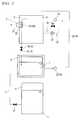
Fig. 2 is a diagram illustrating a laser-oscillation cooling device according to a second embodiment of the present invention. -
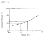
Fig. 3 is a diagram illustrating a relationship of pressure and temperature of a cryogenic liquid in a decompression and return unit according to the embodiments of the present invention. -
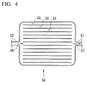
Fig. 4 is a schematic diagram illustrating a micro-channel according to the second embodiment of the present invention. - Hereinafter, a first embodiment of the present invention will be described with reference to the accompanying drawings.
- As illustrated in
Fig. 1 , a laser-oscillation cooling device 1 includes acryostat 2 of which the inside is kept at a low temperature, alaser excitation unit 21 that is disposed on an outer wall of thecryostat 2 and excites a laser beam, astorage tank 3 that stores a cryogenic liquid L therein, a decompression andreturn unit 6 that decompresses the cryogenic liquid L which is provided to cool thelaser excitation unit 21 in thecryostat 2 and returns the cryogenic liquid L to thestorage tank 3, and a pressurization andsupply unit 50 that connects thestorage tank 3 and thecryostat 2 and supplies the cryogenic liquid L stored in thestorage tank 3 to the laser excitation unit. The laser-oscillation cooling device 1 further includes acylinder 4 that supplies the cryogenic liquid L to thestorage tank 3. - The
cryostat 2 is a known device that is generally used for an experiment or the like in which a sample needs to be kept in a low-temperature state. Thecryostat 2 is a box-like container that has a tightly closed space V therein. The space V in thecryostat 2 is thermally isolated from the outside. With the supply of a cooling medium at an extremely low temperature, the inside of the space V is kept at a low temperature. The inside of thecryostat 2 according to this embodiment is pressurized by a pressurization device which is not illustrated, and is substantially kept at 0.3 MPa. - The
cryostat 2 is provided with apressure control unit 10 that lowers a pressure separately from the above-mentioned pressurization device. Thepressure control unit 10 includes apipe line 11 that causes the inside of thecryostat 2 to communicate with the outside, apressure gauge 12 that is connected to apressure control valve 13 and measures the pressure in thecryostat 2, thepressure control valve 13 that can control a degree of opening thereof, and acontroller 14 that adjusts the degree of opening of thepressure control valve 13. - The
controller 14 adjusts the degree of opening of thepressure control valve 13 on the basis of a pressure value in thecryostat 2 which is measured by thepressure gauge 12. When it is detected that the pressure in thecryostat 2 is greater than 0.3 MPa on the basis of the measured value of thepressure gauge 12, thecontroller 14 adjusts the degree of opening of thepressure control valve 12 to increase the degree of opening. When the degree of opening of thepressure control valve 13 increases, gas (gas including an evaporated component of the cryogenic liquid L and air as major components) filled in thecryostat 2 is discharged to the outside via thepipe line 11. Accordingly, the pressure in thecryostat 2 is lowered to an appropriate value (substantially 0.3 MPa). - On the other hand, when the pressure in the
cryostat 2 is lower than 0.3 MPa, thecontroller 14 adjusts the degree of opening of thepressure control valve 13 to decrease the degree of opening. At this time, since the evaporated component of the cryogenic liquid L and the like gradually remain in thecryostat 2, the pressure gradually increases. Thereafter, at a time point at which the pressure reaches a desired value, thepressure control valve 13 is closed. - When a rapid increase in pressure is requested, the inside of the cryostat may be pressurized using the above-mentioned pressurization device.
- The
cryostat 2 is provided with apartition wall 23 that extends upward from the bottom face thereof. Thepartition wall 23 extends to a middle height in a height direction of thecryostat 2. That is, a firstliquid storage bath 24 and a secondliquid storage bath 25 are defined in a lower region in thecryostat 2 by thepartition wall 23 and the inner wall of thecryostat 2. - A
spray nozzle 51 of the pressurization andsupply unit 50, which will be described later, and apipe line 52 connected to thespray nozzle 51 are introduced into thecryostat 2. Thespray nozzle 51 is disposed to spray the cryogenic liquid L supplied via thepipe line 52 toward a cooling andsupport unit 22 of thelaser excitation unit 21. - Here, as the cryogenic liquid L, liquid nitrogen is exemplified in this embodiment. However, the kind of the cryogenic liquid L is not limited to the liquid nitrogen, but any one can be selected and used from a group of liquid-phase inert elements such as liquid helium and liquid neon.
- The
laser excitation unit 21 is disposed in part of the outer wall of thecryostat 2 with the cooling andsupport unit 22. Thelaser excitation unit 21 is a device that amplifies an incident laser beam Z and outputs the amplifier laser beam to the outside. Thelaser excitation unit 21 is constituted, for example, using sapphire or yttrium aluminum garnet (YAG) crystals as a laser excitation medium. - The
laser excitation unit 21 is disposed to protrude to the outside of thecryostat 2. Conversely, the cooling andsupport unit 22 supporting thelaser excitation unit 21 is disposed to face the inside of thecryostat 2. Thelaser excitation unit 21 and the cooling andsupport unit 22 are thermally connected to each other. Accordingly, thelaser excitation unit 21 and the cooling andsupport unit 22 are configured so that a majority of heat transferred to the cooling andsupport unit 22 is immediately transferred to thelaser excitation unit 21. - The
laser excitation unit 21 is disposed above the firstliquid storage bath 24 among the firstliquid storage bath 24 and the secondliquid storage bath 25 which are disposed in thecryostat 2. - The decompression and return
unit 6 connects thecryostat 2 to thestorage tank 3. The decompression and returnunit 6 includes apipe line 61 connecting the secondliquid storage bath 25 in thecryostat 2 to thestorage tank 3 and adecompression valve 62 disposed in the middle of thepipe line 61. - The cryogenic liquid L supplied from the second
liquid storage bath 25 flows in thepipe line 61. The cryogenic liquid L flows to thestorage tank 3 via thepipe line 61. In order to cause the cryogenic liquid L to flow in thepipe line 61, for example, a constitution using a pump which is not illustrated or a constitution causing the cryogenic liquid to fall due to gravity is considered. When the cryogenic liquid is made to fall due to gravity, it is preferable that thecryostat 2 be disposed above thestorage tank 3 to apply a satisfactory gravitational force to the cryogenic liquid L. - The
decompression valve 62 is a known liquid decompression valve that is disposed to lower the pressure of the cryogenic liquid L flowing in thepipe line 61. The cryogenic liquid L passing through thedecompression valve 62 is decompressed and thus decreases in temperature. In this embodiment, the cryogenic liquid L can be lowered to an atmospheric pressure (substantially 0.1 MPa) by thedecompression valve 62. - The
storage tank 3 is a tank that is connected to thecryostat 2 via thepipe line 61 of the decompression and returnunit 6. The cryogenic liquid L flowing through the decompression and returnunit 6 is stored in thestorage tank 3. The pressure in the storage tank is kept substantially equal to the atmospheric pressure. - The pressurization and
supply unit 5 includes thespray nozzle 51 that is introduced into thecryostat 2, thepipe line 52 that connects thespray nozzle 51 to thestorage tank 3 and allows the cryogenic liquid L to flow therein, and apressurization pump 53 that is disposed in thepipe line 52. The pressurization andsupply unit 5 is a device that connects thestorage tank 3 and thecryostat 2 and supplies the cryogenic liquid L stored in thestorage tank 3 to the laser excitation unit 21 (the cooling and support unit 22). - The
spray nozzle 51 is a nozzle member that sprays the cryogenic liquid L supplied via thepipe line 52 from thestorage tank 3 toward the inside of thecryostat 2. A spray hole in thespray nozzle 51 has a diameter sufficiently smaller than that of thepipe line 52. Accordingly, a flow speed of the cryogenic liquid L sprayed from thespray nozzle 51 is higher than a flow speed when the cryogenic liquid passes through thepipe line 52. - The
spray nozzle 51 is disposed at a position at which the cryogenic liquid L can be sprayed toward the cooling andsupport unit 22 integrally disposed with thelaser excitation unit 21. - The
pressurization pump 53 is a known liquid pump that feeds a liquid along thepipe line 52 by pressurizing the liquid passing therein. That is, the cryogenic liquid L is fed in a direction from thestorage tank 3 to thespray nozzle 51 along thepipe line 52 by thepressurization pump 53. - The
cylinder 4 is a container that contains the cryogenic liquid L therein. The cryogenic liquid L in a liquid phase is stored in the cylinder. Thecylinder 4 is connected to thestorage tank 3 via a pipe line 7. A flowrate adjusting valve 71 is disposed in the pipe line 7. It is possible to adjust the flow rate of the cryogenic liquid L supplied from thecylinder 4 to thestorage tank 3 by opening and closing the flowrate adjusting valve 71. That is, when the amount of cryogenic liquid L in thestorage tank 3 decreases, the storage tank can be supplemented with the cryogenic liquid L from thecylinder 4 by opening the flowrate adjusting valve 71. Although not illustrated in the drawing, a liquid level sensor that senses a liquid level of the cryogenic liquid L in thestorage tank 3 and a control unit that controls the opening and closing of the flowrate adjusting valve 71 depending on the output of the liquid level sensor may be separately provided. - According to this constitution, it is possible to autonomously supply the cryogenic liquid L to the
storage tank 3. - Subsequently, an operation of the laser-
oscillation cooling device 1 according to this embodiment will be described. - First, the
laser excitation unit 21 is irradiated with the laser beam Z from a light source which is not illustrated. The laser beam Z is excited by the excitation medium in thelaser excitation unit 21 and is irradiated toward the outside from thelaser excitation unit 21. At this time, thelaser excitation unit 21 locally emits heat by irradiation with the laser beam Z. Specifically, the amount of heat emitted reaches 0.25 KW per square centimeter. Accordingly, thelaser excitation unit 21 needs to be cooled via the cooling andsupport unit 22. - In order to cool the
laser excitation unit 21, the flowrate adjusting valve 71 is first opened to supply the cryogenic liquid L from thecylinder 4 to thestorage tank 3. When it is confirmed that a desired amount of cryogenic liquid L is stored in thestorage tank 3, thepressurization pump 53 is driven. - When the
pressurization pump 53 is driven, the cryogenic liquid L stored in thestorage tank 3 is supplied to thespray nozzle 51 via thepipe line 52. The cryogenic liquid L reached thespray nozzle 51 is sprayed from thespray nozzle 51 toward the cooling andsupport unit 22 in thecryostat 2. Accordingly, the cooling andsupport unit 22 in a high-temperature state is cooled. Here, part of the cryogenic liquid L cooled the cooling andsupport unit 22 is evaporated due to the high temperature of the cooling andsupport unit 22 and stays in thecryostat 2. The component of the cryogenic liquid L which is evaporated due to the cooling is substantially about 1 percent by volume. - Since liquid nitrogen is used as the cryogenic liquid L in this embodiment, the temperature of the cryogenic liquid L in the
storage tank 3 under the atmospheric pressure (about 0.1 MPa) is equal to or lower than -196°C. On the other hand, since the inside of thecryostat 2 is pressurized to about 0.3 MPa as described above, the temperature of the cryogenic liquid L sprayed from thespray nozzle 51 increases to about -180°C (seeFig. 3 ). In this way, by spraying the cryogenic liquid L of a temperature about -180°C, the cooling andsupport unit 22 is satisfactorily cooled. - The cryogenic liquid L provided to cool the cooling and
support unit 22 drops downward from the cooling andsupport unit 22. As described above, the firstliquid storage bath 24 is disposed below the cooling andsupport unit 22. Accordingly, the dropping cryogenic liquid L is stored in the firstliquid storage bath 24. Since the amount of cryogenic liquid L which is provided for the cooling and evaporated is substantially 1 percent by volume as described above, the cryogenic liquid L stored in the firstliquid storage bath 24 is about 99 percent by volume of the amount of cryogenic liquid supplied from thespray nozzle 51. - By continuously spraying the cryogenic liquid L toward the cooling and
support unit 22 in the above-mentioned state, thelaser excitation unit 21 is continuously cooled. By continuously performing the cooling, the amount of cryogenic liquid L stored in the firstliquid storage bath 24 gradually increases. As a result, the liquid level of the cryogenic liquid L stored in the firstliquid storage bath 24 reaches a dimension to which thepartition wall 23 extends. - Thereafter, when the cooling is additionally continuously performed, the liquid level of the cryogenic liquid L exceeds the
partition wall 23. In other words, the cryogenic liquid L flows over the firstliquid storage bath 24 and flows to the secondliquid storage bath 25 adjacent thereto. Thereafter, the cryogenic liquid L is stored in the secondliquid storage bath 25. - Subsequently, when the liquid level of the cryogenic liquid L stored in the second
liquid storage bath 25 reaches a predetermined value, thedecompression valve 62 is opened. That is, until a predetermined amount of cryogenic liquid L is stored in the secondliquid storage bath 25, thedecompression valve 62 is not opened. Here, when the amount of cryogenic liquid L stored is small and thedecompression valve 62 is opened, a sufficient flow rate is not achieved and a possibility exists that gas in thecryostat 2 may be involved with the flow of the cryogenic liquid. - In the
cryostat 2 according to this embodiment, the firstliquid storage bath 24 and the secondliquid storage bath 25 are formed by thepartition wall 23. According to this constitution, a constant amount of cryogenic liquid L is stored in the firstliquid storage bath 24 during operation of the laser-oscillation cooling device 1. Accordingly, since the temperature in thecryostat 2 is kept at a low temperature by the cryogenic liquid L stored in the firstliquid storage bath 24, it is possible to more effectively cool thelaser excitation unit 21. Even when the amount of cryogenic liquid L stored in the secondliquid storage bath 25 varies by opening thedecompression valve 62, it is possible to suppress a rapid variation of the temperature in thecryostat 2. - The cryogenic liquid L passing through the
decompression valve 62 flows to thestorage tank 3. That is, the cryogenic liquid L supplied from thestorage tank 3 via thespray nozzle 51 is returned to thestorage tank 3 by the decompression and returnunit 6. - As described above, about 99 percent by volume of the cryogenic liquid L is stored in the first
liquid storage bath 24 and the secondliquid storage bath 25. Most of the cryogenic liquid L stored in the secondliquid storage bath 25 can be recovered and returned to thestorage tank 3 by the decompression and returnunit 6. Accordingly, it is possible to recover and reuse about 99 percent of the entire cryogenic liquid L. That is, according to the laser-oscillation cooling device 1, it is possible to satisfactorily cool thelaser excitation unit 21 in a high-temperature state and to recover and reuse the cryogenic liquid L as a cooling medium with high efficiency. - According to the above-mentioned constitution, the decompression and return
unit 6 includes thedecompression valve 62 that decompresses the cryogenic liquid L. According to this constitution, it is possible to sufficiently decompress the cryogenic liquid L by causing the cryogenic liquid L to pass through thedecompression valve 62 and to simply constitute the decompression and returnunit 6. - In the above-mentioned constitution, the
laser excitation unit 21 is disposed in thecryostat 2. According to this constitution, since the surrounding of thelaser excitation unit 21 and the cooling andsupport unit 22 can be kept at a low temperature, it is possible to more effectively cool thelaser excitation unit 21 as a heat-emitting body. - In the above-mentioned constitution, the pressurization and
supply unit 50 is provided with thespray nozzle 51 that sprays the cryogenic liquid L onto thelaser excitation unit 21. According to this constitution, since the cryogenic liquid L can be supplied to thelaser excitation unit 21 at a higher flow speed by spraying the cryogenic liquid L from thespray nozzle 51, it is possible to more effectively cool thelaser excitation unit 21. - While an embodiment of the present invention has been described above with reference to the drawings, the specific constitution thereof is not limited to the embodiment but includes modifications in design without departing from the gist of the present invention.
- Hereinafter, a second embodiment of the present invention will be described with reference to the accompanying drawings.
- The same elements as in the above-mentioned first embodiment will be referenced by the same reference signs and detailed description thereof will not be repeated.
- As illustrated in
Fig. 3 , a laser-oscillation cooling device 1 according to this embodiment is different from the laser-oscillation cooling device according to the first embodiment in the following points. That is, in this embodiment, a micro-channel 54 is disposed in thecryostat 2. More specifically, the micro-channel 54 is disposed to come in contact with the cooling andsupport unit 22. More preferably, the micro-channel 54 has a size which covers the entire surface of the cooling andsupport unit 22. - The micro-channel 54 is a known cooling device in which a plurality of pipe-
like channels 55 are arranged. Ends on one side of the plurality of pipe-like channels 55 are merged into one channel which serves as aninflow port 56. Ends on the other side of the plurality of pipe-like channels 55 are merged into one channel which serves as anoutflow port 57. Theinflow port 56 is connected to the above-mentionedpipe line 52. That is, the cryogenic liquid L flows into the micro-channel 54 via theinflow port 56, passes through the plurality of pipe-like channels 55, and is discharged to thepipe line 61 via theoutflow port 57. - As described above, the micro-channel 54 has such a size which covers the entire surface of the cooling and
support unit 22. Accordingly, the cryogenic liquid L widely diffuses to the entire surface of the cooling andsupport unit 22 via the plurality of pipe-like channels 55. As a result, it is possible to more effectively cool the cooling andsupport unit 22. - According to the above-mentioned laser-oscillation cooling device, it is possible to achieve a satisfactory cooling effect of an object and to appropriately recover a cooling medium.
-
- 1
- Laser-oscillation cooling device
- 2
- Cryostat
- 3
- Storage tank
- 4
- Cylinder
- 5
- Pressurization and supply unit
- 6
- Decompression and return unit
- 7
- Pipe line
- 10
- Pressure control unit
- 11
- Pipe line
- 12
- Pressure gauge
- 13
- Pressure control valve
- 14
- Controller
- 21
- Laser excitation unit
- 22
- Cooling and support unit
- 23
- Partition wall
- 24
- First liquid storage bath
- 25
- Second liquid storage bath
- 51
- Spray nozzle
- 52
- Pipe line
- 53
- Pressurization pump
- 61
- Pipe line
- 62
- Decompression valve
- 71
- Flow rate adjusting valve
- L
- Cryogenic liquid
- V
- Space
- Z
- Laser beam
Claims (5)
- A laser-oscillation cooling device comprising:a laser excitation unit that excites a laser beam and locally emits heat;a storage tank capable of storing a cryogenic liquid at an atmospheric pressure and discharging the cryogenic liquid which is evaporated;a pressurization and supply unit that pressurizes the cryogenic liquid stored in the storage tank and supplies the pressurized cryogenic liquid to the laser excitation unit; anda decompression and return unit that decompresses the cryogenic liquid which is supplied to the laser excitation unit and used to cool the laser excitation unit and returns the cryogenic liquid to the storage tank.
- The laser-oscillation cooling device according to claim 1, wherein the decompression and return unit includes a decompression valve that decompresses the cryogenic liquid.
- The laser-oscillation cooling device according to claim 1 or 2, wherein the laser excitation unit is disposed in a cryostat of which the inside is kept at a low temperature.
- The laser-oscillation cooling device according to any one of claims 1 to 3, wherein the pressurization and supply unit includes a spray nozzle that sprays the cryogenic liquid toward the laser excitation unit.
- The laser-oscillation cooling device according to any one of claims 1 to 3, wherein the pressurization and supply unit includes a micro-channel that is disposed to come in contact with the laser excitation unit and in which the pressurized cryogenic liquid flows.
Applications Claiming Priority (2)
| Application Number | Priority Date | Filing Date | Title |
|---|---|---|---|
| JP2014058886A JP6206671B2 (en) | 2014-03-20 | 2014-03-20 | Laser oscillation cooling device |
| PCT/JP2015/055612 WO2015141430A1 (en) | 2014-03-20 | 2015-02-26 | Laser-oscillation cooling device |
Publications (3)
| Publication Number | Publication Date |
|---|---|
| EP3067999A1 true EP3067999A1 (en) | 2016-09-14 |
| EP3067999A4 EP3067999A4 (en) | 2017-02-01 |
| EP3067999B1 EP3067999B1 (en) | 2021-04-14 |
Family
ID=54144406
Family Applications (1)
| Application Number | Title | Priority Date | Filing Date |
|---|---|---|---|
| EP15765048.2A Active EP3067999B1 (en) | 2014-03-20 | 2015-02-26 | Laser-oscillation cooling device |
Country Status (4)
| Country | Link |
|---|---|
| US (1) | US9825418B2 (en) |
| EP (1) | EP3067999B1 (en) |
| JP (1) | JP6206671B2 (en) |
| WO (1) | WO2015141430A1 (en) |
Families Citing this family (4)
| Publication number | Priority date | Publication date | Assignee | Title |
|---|---|---|---|---|
| JPWO2021044575A1 (en) * | 2019-09-05 | 2021-03-11 | ||
| US11919170B2 (en) * | 2019-12-13 | 2024-03-05 | Edda Technology, Inc. | Fast method for robot path planning with obstacle avoidance |
| CN119362118B (en) * | 2024-12-23 | 2025-03-11 | 厦门纽立特电子科技有限公司 | End pump multi-pass lath laser amplifier |
| CN120730705A (en) * | 2025-08-25 | 2025-09-30 | 浪潮电子信息产业股份有限公司 | Server cabinet, server and server control method |
Family Cites Families (17)
| Publication number | Priority date | Publication date | Assignee | Title |
|---|---|---|---|---|
| JPS61501588A (en) * | 1983-07-22 | 1986-07-31 | オ−ストラリア国 | cavity cooling |
| FR2690286A1 (en) * | 1992-04-17 | 1993-10-22 | Commissariat Energie Atomique | Laser cavity with asymmetrical semi-conductor heterostructure and laser equipped with this cavity. |
| JPH0668725A (en) | 1992-08-18 | 1994-03-11 | Mitsubishi Electric Corp | Manufacture of superconducting alloy wire |
| DE4437489C1 (en) * | 1994-10-20 | 1996-03-28 | Zeiss Carl Fa | Cooling device for a pulsed laser and method for operating such a cooling device |
| JP2961072B2 (en) * | 1995-06-23 | 1999-10-12 | 株式会社神戸製鋼所 | Oxygen and nitrogen liquefaction equipment |
| JP3067686B2 (en) * | 1997-04-21 | 2000-07-17 | 日本電気株式会社 | Solid-state laser device |
| US6195372B1 (en) * | 1997-08-19 | 2001-02-27 | David C. Brown | Cryogenically-cooled solid-state lasers |
| JP2002246522A (en) | 2001-02-21 | 2002-08-30 | Mitsubishi Heavy Ind Ltd | Solid-state laser cooling device and heat sink |
| JP3951782B2 (en) | 2002-04-17 | 2007-08-01 | 三菱電機株式会社 | Semiconductor laser pumped solid state laser amplifier, semiconductor laser pumped solid state laser apparatus, and semiconductor laser cooling method in semiconductor laser pumped solid state laser amplifier |
| JP4627445B2 (en) * | 2005-02-23 | 2011-02-09 | 浜松ホトニクス株式会社 | Laser amplifier |
| JP2008027780A (en) * | 2006-07-21 | 2008-02-07 | Sumitomo Electric Ind Ltd | Liquid refrigerant circulation cooling system |
| JP2010135704A (en) * | 2008-12-08 | 2010-06-17 | Mitsubishi Electric Corp | Cooling system of semiconductor laser package |
| US8509281B2 (en) * | 2010-02-11 | 2013-08-13 | The Boeing Company | Disk laser |
| US20120113513A1 (en) * | 2010-10-22 | 2012-05-10 | The Regents Of The University Of Colorado, A Body Corporate | Self-cleaning of optical surfaces in low-pressure reactive gas environments in advanced optical systems |
| US9209598B1 (en) * | 2011-12-14 | 2015-12-08 | Colorado State University Research Foundation | Cooling system for high average power laser |
| JP5837523B2 (en) * | 2012-03-27 | 2015-12-24 | 富士フイルム株式会社 | COOLING SYSTEM, RESERVO UNIT AND CARTRIDGE, AND SOLID-STATE LASER OSCILLATION EQUIPPED |
| JP2013228574A (en) * | 2012-04-26 | 2013-11-07 | Seiko Epson Corp | Wave plate and electronic device |
-
2014
- 2014-03-20 JP JP2014058886A patent/JP6206671B2/en active Active
-
2015
- 2015-02-26 EP EP15765048.2A patent/EP3067999B1/en active Active
- 2015-02-26 WO PCT/JP2015/055612 patent/WO2015141430A1/en not_active Ceased
- 2015-02-26 US US15/103,113 patent/US9825418B2/en active Active
Also Published As
| Publication number | Publication date |
|---|---|
| JP2015185601A (en) | 2015-10-22 |
| US20160308326A1 (en) | 2016-10-20 |
| EP3067999B1 (en) | 2021-04-14 |
| WO2015141430A1 (en) | 2015-09-24 |
| EP3067999A4 (en) | 2017-02-01 |
| JP6206671B2 (en) | 2017-10-04 |
| US9825418B2 (en) | 2017-11-21 |
Similar Documents
| Publication | Publication Date | Title |
|---|---|---|
| EP3067999B1 (en) | Laser-oscillation cooling device | |
| US10199240B2 (en) | Substrate processing method, substrate processing apparatus, and storage medium | |
| JP6640260B2 (en) | Pressurizing apparatus using cooling combining fan and ejector, and method of pressurizing | |
| KR20110128297A (en) | Plant for the storage and supply of compressed gas | |
| WO2011138717A3 (en) | Improved method and apparatus for shipping and storage of cryogenic devices | |
| JP6238498B2 (en) | Heat treatment device and cooling device | |
| KR20130039445A (en) | Superconductive electromagnet apparatus | |
| JP6626816B2 (en) | Superconducting coil precooling method and superconducting magnet device | |
| JP7674877B2 (en) | SUBSTRATE PROCESSING METHOD AND SUBSTRATE PROCESSING APPARATUS | |
| JP2564338B2 (en) | Superconducting coil cooling method and superconducting device | |
| US7854132B2 (en) | Circulation cooling system of cryogenic cable | |
| KR20060033023A (en) | Cooling method and device | |
| KR20130035195A (en) | Substrate processing apparatus | |
| JP2014527606A (en) | Method and apparatus for refilling a storage tank | |
| EP3196990B1 (en) | Laser oscillation cooling device | |
| JP3618703B2 (en) | Pressure heating method and pressure heating apparatus | |
| JP5638049B2 (en) | Loop type heat pipe | |
| KR20140056145A (en) | Cooling device for a super conductor and super conducting synchronous machine | |
| JP2015185601A5 (en) | ||
| US20190135159A1 (en) | Cooling apparatus and a vehicle including the same | |
| US20190353148A1 (en) | Liquid supply system | |
| JP2007506932A (en) | System for liquefying or freezing xenon | |
| JP3908975B2 (en) | Cooling device and cooling method | |
| ES3007757T3 (en) | A method in a pressing arrangement | |
| KR101022388B1 (en) | Satellite propulsion device and propulsion method using Nusen pump |
Legal Events
| Date | Code | Title | Description |
|---|---|---|---|
| PUAI | Public reference made under article 153(3) epc to a published international application that has entered the european phase |
Free format text: ORIGINAL CODE: 0009012 |
|
| 17P | Request for examination filed |
Effective date: 20160606 |
|
| AK | Designated contracting states |
Kind code of ref document: A1 Designated state(s): AL AT BE BG CH CY CZ DE DK EE ES FI FR GB GR HR HU IE IS IT LI LT LU LV MC MK MT NL NO PL PT RO RS SE SI SK SM TR |
|
| AX | Request for extension of the european patent |
Extension state: BA ME |
|
| A4 | Supplementary search report drawn up and despatched |
Effective date: 20170105 |
|
| RIC1 | Information provided on ipc code assigned before grant |
Ipc: H01L 23/473 20060101ALI20161223BHEP Ipc: H05K 7/20 20060101ALI20161223BHEP Ipc: H01S 3/042 20060101AFI20161223BHEP |
|
| DAX | Request for extension of the european patent (deleted) | ||
| STAA | Information on the status of an ep patent application or granted ep patent |
Free format text: STATUS: EXAMINATION IS IN PROGRESS |
|
| 17Q | First examination report despatched |
Effective date: 20180528 |
|
| GRAP | Despatch of communication of intention to grant a patent |
Free format text: ORIGINAL CODE: EPIDOSNIGR1 |
|
| STAA | Information on the status of an ep patent application or granted ep patent |
Free format text: STATUS: GRANT OF PATENT IS INTENDED |
|
| INTG | Intention to grant announced |
Effective date: 20210114 |
|
| GRAS | Grant fee paid |
Free format text: ORIGINAL CODE: EPIDOSNIGR3 |
|
| GRAA | (expected) grant |
Free format text: ORIGINAL CODE: 0009210 |
|
| STAA | Information on the status of an ep patent application or granted ep patent |
Free format text: STATUS: THE PATENT HAS BEEN GRANTED |
|
| AK | Designated contracting states |
Kind code of ref document: B1 Designated state(s): AL AT BE BG CH CY CZ DE DK EE ES FI FR GB GR HR HU IE IS IT LI LT LU LV MC MK MT NL NO PL PT RO RS SE SI SK SM TR |
|
| REG | Reference to a national code |
Ref country code: GB Ref legal event code: FG4D |
|
| REG | Reference to a national code |
Ref country code: CH Ref legal event code: EP |
|
| REG | Reference to a national code |
Ref country code: DE Ref legal event code: R096 Ref document number: 602015068117 Country of ref document: DE |
|
| REG | Reference to a national code |
Ref country code: IE Ref legal event code: FG4D |
|
| REG | Reference to a national code |
Ref country code: AT Ref legal event code: REF Ref document number: 1383301 Country of ref document: AT Kind code of ref document: T Effective date: 20210515 |
|
| REG | Reference to a national code |
Ref country code: LT Ref legal event code: MG9D |
|
| REG | Reference to a national code |
Ref country code: AT Ref legal event code: MK05 Ref document number: 1383301 Country of ref document: AT Kind code of ref document: T Effective date: 20210414 |
|
| REG | Reference to a national code |
Ref country code: NL Ref legal event code: MP Effective date: 20210414 |
|
| PG25 | Lapsed in a contracting state [announced via postgrant information from national office to epo] |
Ref country code: AT Free format text: LAPSE BECAUSE OF FAILURE TO SUBMIT A TRANSLATION OF THE DESCRIPTION OR TO PAY THE FEE WITHIN THE PRESCRIBED TIME-LIMIT Effective date: 20210414 Ref country code: BG Free format text: LAPSE BECAUSE OF FAILURE TO SUBMIT A TRANSLATION OF THE DESCRIPTION OR TO PAY THE FEE WITHIN THE PRESCRIBED TIME-LIMIT Effective date: 20210714 Ref country code: HR Free format text: LAPSE BECAUSE OF FAILURE TO SUBMIT A TRANSLATION OF THE DESCRIPTION OR TO PAY THE FEE WITHIN THE PRESCRIBED TIME-LIMIT Effective date: 20210414 Ref country code: FI Free format text: LAPSE BECAUSE OF FAILURE TO SUBMIT A TRANSLATION OF THE DESCRIPTION OR TO PAY THE FEE WITHIN THE PRESCRIBED TIME-LIMIT Effective date: 20210414 Ref country code: LT Free format text: LAPSE BECAUSE OF FAILURE TO SUBMIT A TRANSLATION OF THE DESCRIPTION OR TO PAY THE FEE WITHIN THE PRESCRIBED TIME-LIMIT Effective date: 20210414 Ref country code: NL Free format text: LAPSE BECAUSE OF FAILURE TO SUBMIT A TRANSLATION OF THE DESCRIPTION OR TO PAY THE FEE WITHIN THE PRESCRIBED TIME-LIMIT Effective date: 20210414 |
|
| PG25 | Lapsed in a contracting state [announced via postgrant information from national office to epo] |
Ref country code: GR Free format text: LAPSE BECAUSE OF FAILURE TO SUBMIT A TRANSLATION OF THE DESCRIPTION OR TO PAY THE FEE WITHIN THE PRESCRIBED TIME-LIMIT Effective date: 20210715 Ref country code: LV Free format text: LAPSE BECAUSE OF FAILURE TO SUBMIT A TRANSLATION OF THE DESCRIPTION OR TO PAY THE FEE WITHIN THE PRESCRIBED TIME-LIMIT Effective date: 20210414 Ref country code: IS Free format text: LAPSE BECAUSE OF FAILURE TO SUBMIT A TRANSLATION OF THE DESCRIPTION OR TO PAY THE FEE WITHIN THE PRESCRIBED TIME-LIMIT Effective date: 20210814 Ref country code: SE Free format text: LAPSE BECAUSE OF FAILURE TO SUBMIT A TRANSLATION OF THE DESCRIPTION OR TO PAY THE FEE WITHIN THE PRESCRIBED TIME-LIMIT Effective date: 20210414 Ref country code: RS Free format text: LAPSE BECAUSE OF FAILURE TO SUBMIT A TRANSLATION OF THE DESCRIPTION OR TO PAY THE FEE WITHIN THE PRESCRIBED TIME-LIMIT Effective date: 20210414 Ref country code: ES Free format text: LAPSE BECAUSE OF FAILURE TO SUBMIT A TRANSLATION OF THE DESCRIPTION OR TO PAY THE FEE WITHIN THE PRESCRIBED TIME-LIMIT Effective date: 20210414 Ref country code: PT Free format text: LAPSE BECAUSE OF FAILURE TO SUBMIT A TRANSLATION OF THE DESCRIPTION OR TO PAY THE FEE WITHIN THE PRESCRIBED TIME-LIMIT Effective date: 20210816 Ref country code: NO Free format text: LAPSE BECAUSE OF FAILURE TO SUBMIT A TRANSLATION OF THE DESCRIPTION OR TO PAY THE FEE WITHIN THE PRESCRIBED TIME-LIMIT Effective date: 20210714 Ref country code: PL Free format text: LAPSE BECAUSE OF FAILURE TO SUBMIT A TRANSLATION OF THE DESCRIPTION OR TO PAY THE FEE WITHIN THE PRESCRIBED TIME-LIMIT Effective date: 20210414 |
|
| REG | Reference to a national code |
Ref country code: DE Ref legal event code: R097 Ref document number: 602015068117 Country of ref document: DE |
|
| PG25 | Lapsed in a contracting state [announced via postgrant information from national office to epo] |
Ref country code: RO Free format text: LAPSE BECAUSE OF FAILURE TO SUBMIT A TRANSLATION OF THE DESCRIPTION OR TO PAY THE FEE WITHIN THE PRESCRIBED TIME-LIMIT Effective date: 20210414 Ref country code: SM Free format text: LAPSE BECAUSE OF FAILURE TO SUBMIT A TRANSLATION OF THE DESCRIPTION OR TO PAY THE FEE WITHIN THE PRESCRIBED TIME-LIMIT Effective date: 20210414 Ref country code: SK Free format text: LAPSE BECAUSE OF FAILURE TO SUBMIT A TRANSLATION OF THE DESCRIPTION OR TO PAY THE FEE WITHIN THE PRESCRIBED TIME-LIMIT Effective date: 20210414 Ref country code: EE Free format text: LAPSE BECAUSE OF FAILURE TO SUBMIT A TRANSLATION OF THE DESCRIPTION OR TO PAY THE FEE WITHIN THE PRESCRIBED TIME-LIMIT Effective date: 20210414 Ref country code: CZ Free format text: LAPSE BECAUSE OF FAILURE TO SUBMIT A TRANSLATION OF THE DESCRIPTION OR TO PAY THE FEE WITHIN THE PRESCRIBED TIME-LIMIT Effective date: 20210414 Ref country code: DK Free format text: LAPSE BECAUSE OF FAILURE TO SUBMIT A TRANSLATION OF THE DESCRIPTION OR TO PAY THE FEE WITHIN THE PRESCRIBED TIME-LIMIT Effective date: 20210414 |
|
| PLBE | No opposition filed within time limit |
Free format text: ORIGINAL CODE: 0009261 |
|
| STAA | Information on the status of an ep patent application or granted ep patent |
Free format text: STATUS: NO OPPOSITION FILED WITHIN TIME LIMIT |
|
| 26N | No opposition filed |
Effective date: 20220117 |
|
| PG25 | Lapsed in a contracting state [announced via postgrant information from national office to epo] |
Ref country code: IS Free format text: LAPSE BECAUSE OF FAILURE TO SUBMIT A TRANSLATION OF THE DESCRIPTION OR TO PAY THE FEE WITHIN THE PRESCRIBED TIME-LIMIT Effective date: 20210814 Ref country code: AL Free format text: LAPSE BECAUSE OF FAILURE TO SUBMIT A TRANSLATION OF THE DESCRIPTION OR TO PAY THE FEE WITHIN THE PRESCRIBED TIME-LIMIT Effective date: 20210414 |
|
| PG25 | Lapsed in a contracting state [announced via postgrant information from national office to epo] |
Ref country code: IT Free format text: LAPSE BECAUSE OF FAILURE TO SUBMIT A TRANSLATION OF THE DESCRIPTION OR TO PAY THE FEE WITHIN THE PRESCRIBED TIME-LIMIT Effective date: 20210414 |
|
| PG25 | Lapsed in a contracting state [announced via postgrant information from national office to epo] |
Ref country code: MC Free format text: LAPSE BECAUSE OF FAILURE TO SUBMIT A TRANSLATION OF THE DESCRIPTION OR TO PAY THE FEE WITHIN THE PRESCRIBED TIME-LIMIT Effective date: 20210414 |
|
| REG | Reference to a national code |
Ref country code: CH Ref legal event code: PL |
|
| REG | Reference to a national code |
Ref country code: BE Ref legal event code: MM Effective date: 20220228 |
|
| PG25 | Lapsed in a contracting state [announced via postgrant information from national office to epo] |
Ref country code: LU Free format text: LAPSE BECAUSE OF NON-PAYMENT OF DUE FEES Effective date: 20220226 |
|
| PG25 | Lapsed in a contracting state [announced via postgrant information from national office to epo] |
Ref country code: LI Free format text: LAPSE BECAUSE OF NON-PAYMENT OF DUE FEES Effective date: 20220228 Ref country code: IE Free format text: LAPSE BECAUSE OF NON-PAYMENT OF DUE FEES Effective date: 20220226 Ref country code: CH Free format text: LAPSE BECAUSE OF NON-PAYMENT OF DUE FEES Effective date: 20220228 |
|
| PG25 | Lapsed in a contracting state [announced via postgrant information from national office to epo] |
Ref country code: BE Free format text: LAPSE BECAUSE OF NON-PAYMENT OF DUE FEES Effective date: 20220228 |
|
| PG25 | Lapsed in a contracting state [announced via postgrant information from national office to epo] |
Ref country code: HU Free format text: LAPSE BECAUSE OF FAILURE TO SUBMIT A TRANSLATION OF THE DESCRIPTION OR TO PAY THE FEE WITHIN THE PRESCRIBED TIME-LIMIT; INVALID AB INITIO Effective date: 20150226 |
|
| PG25 | Lapsed in a contracting state [announced via postgrant information from national office to epo] |
Ref country code: MK Free format text: LAPSE BECAUSE OF FAILURE TO SUBMIT A TRANSLATION OF THE DESCRIPTION OR TO PAY THE FEE WITHIN THE PRESCRIBED TIME-LIMIT Effective date: 20210414 Ref country code: CY Free format text: LAPSE BECAUSE OF FAILURE TO SUBMIT A TRANSLATION OF THE DESCRIPTION OR TO PAY THE FEE WITHIN THE PRESCRIBED TIME-LIMIT Effective date: 20210414 |
|
| PG25 | Lapsed in a contracting state [announced via postgrant information from national office to epo] |
Ref country code: MT Free format text: LAPSE BECAUSE OF FAILURE TO SUBMIT A TRANSLATION OF THE DESCRIPTION OR TO PAY THE FEE WITHIN THE PRESCRIBED TIME-LIMIT Effective date: 20210414 |
|
| PG25 | Lapsed in a contracting state [announced via postgrant information from national office to epo] |
Ref country code: TR Free format text: LAPSE BECAUSE OF FAILURE TO SUBMIT A TRANSLATION OF THE DESCRIPTION OR TO PAY THE FEE WITHIN THE PRESCRIBED TIME-LIMIT Effective date: 20210414 |
|
| PGFP | Annual fee paid to national office [announced via postgrant information from national office to epo] |
Ref country code: FR Payment date: 20251231 Year of fee payment: 12 |
|
| PGFP | Annual fee paid to national office [announced via postgrant information from national office to epo] |
Ref country code: GB Payment date: 20260106 Year of fee payment: 12 |
|
| PGFP | Annual fee paid to national office [announced via postgrant information from national office to epo] |
Ref country code: DE Payment date: 20260102 Year of fee payment: 12 |