EP3067962A1 - Battery pack - Google Patents
Battery pack Download PDFInfo
- Publication number
- EP3067962A1 EP3067962A1 EP16159706.7A EP16159706A EP3067962A1 EP 3067962 A1 EP3067962 A1 EP 3067962A1 EP 16159706 A EP16159706 A EP 16159706A EP 3067962 A1 EP3067962 A1 EP 3067962A1
- Authority
- EP
- European Patent Office
- Prior art keywords
- cooling plate
- bracket
- battery pack
- plate
- battery
- Prior art date
- Legal status (The legal status is an assumption and is not a legal conclusion. Google has not performed a legal analysis and makes no representation as to the accuracy of the status listed.)
- Granted
Links
Images

Classifications
-
- H—ELECTRICITY
- H01—ELECTRIC ELEMENTS
- H01M—PROCESSES OR MEANS, e.g. BATTERIES, FOR THE DIRECT CONVERSION OF CHEMICAL ENERGY INTO ELECTRICAL ENERGY
- H01M10/00—Secondary cells; Manufacture thereof
- H01M10/60—Heating or cooling; Temperature control
- H01M10/65—Means for temperature control structurally associated with the cells
- H01M10/655—Solid structures for heat exchange or heat conduction
- H01M10/6554—Rods or plates
- H01M10/6555—Rods or plates arranged between the cells
-
- H—ELECTRICITY
- H01—ELECTRIC ELEMENTS
- H01M—PROCESSES OR MEANS, e.g. BATTERIES, FOR THE DIRECT CONVERSION OF CHEMICAL ENERGY INTO ELECTRICAL ENERGY
- H01M10/00—Secondary cells; Manufacture thereof
- H01M10/60—Heating or cooling; Temperature control
- H01M10/65—Means for temperature control structurally associated with the cells
- H01M10/655—Solid structures for heat exchange or heat conduction
- H01M10/6554—Rods or plates
-
- H—ELECTRICITY
- H01—ELECTRIC ELEMENTS
- H01M—PROCESSES OR MEANS, e.g. BATTERIES, FOR THE DIRECT CONVERSION OF CHEMICAL ENERGY INTO ELECTRICAL ENERGY
- H01M10/00—Secondary cells; Manufacture thereof
- H01M10/04—Construction or manufacture in general
-
- H—ELECTRICITY
- H01—ELECTRIC ELEMENTS
- H01M—PROCESSES OR MEANS, e.g. BATTERIES, FOR THE DIRECT CONVERSION OF CHEMICAL ENERGY INTO ELECTRICAL ENERGY
- H01M10/00—Secondary cells; Manufacture thereof
- H01M10/60—Heating or cooling; Temperature control
- H01M10/61—Types of temperature control
- H01M10/613—Cooling or keeping cold
-
- H—ELECTRICITY
- H01—ELECTRIC ELEMENTS
- H01M—PROCESSES OR MEANS, e.g. BATTERIES, FOR THE DIRECT CONVERSION OF CHEMICAL ENERGY INTO ELECTRICAL ENERGY
- H01M10/00—Secondary cells; Manufacture thereof
- H01M10/60—Heating or cooling; Temperature control
- H01M10/61—Types of temperature control
- H01M10/615—Heating or keeping warm
-
- H—ELECTRICITY
- H01—ELECTRIC ELEMENTS
- H01M—PROCESSES OR MEANS, e.g. BATTERIES, FOR THE DIRECT CONVERSION OF CHEMICAL ENERGY INTO ELECTRICAL ENERGY
- H01M10/00—Secondary cells; Manufacture thereof
- H01M10/60—Heating or cooling; Temperature control
- H01M10/61—Types of temperature control
- H01M10/617—Types of temperature control for achieving uniformity or desired distribution of temperature
-
- H—ELECTRICITY
- H01—ELECTRIC ELEMENTS
- H01M—PROCESSES OR MEANS, e.g. BATTERIES, FOR THE DIRECT CONVERSION OF CHEMICAL ENERGY INTO ELECTRICAL ENERGY
- H01M10/00—Secondary cells; Manufacture thereof
- H01M10/60—Heating or cooling; Temperature control
- H01M10/62—Heating or cooling; Temperature control specially adapted for specific applications
- H01M10/625—Vehicles
-
- H—ELECTRICITY
- H01—ELECTRIC ELEMENTS
- H01M—PROCESSES OR MEANS, e.g. BATTERIES, FOR THE DIRECT CONVERSION OF CHEMICAL ENERGY INTO ELECTRICAL ENERGY
- H01M10/00—Secondary cells; Manufacture thereof
- H01M10/60—Heating or cooling; Temperature control
- H01M10/65—Means for temperature control structurally associated with the cells
- H01M10/655—Solid structures for heat exchange or heat conduction
- H01M10/6556—Solid parts with flow channel passages or pipes for heat exchange
-
- H—ELECTRICITY
- H01—ELECTRIC ELEMENTS
- H01M—PROCESSES OR MEANS, e.g. BATTERIES, FOR THE DIRECT CONVERSION OF CHEMICAL ENERGY INTO ELECTRICAL ENERGY
- H01M10/00—Secondary cells; Manufacture thereof
- H01M10/60—Heating or cooling; Temperature control
- H01M10/65—Means for temperature control structurally associated with the cells
- H01M10/655—Solid structures for heat exchange or heat conduction
- H01M10/6556—Solid parts with flow channel passages or pipes for heat exchange
- H01M10/6557—Solid parts with flow channel passages or pipes for heat exchange arranged between the cells
-
- H—ELECTRICITY
- H01—ELECTRIC ELEMENTS
- H01M—PROCESSES OR MEANS, e.g. BATTERIES, FOR THE DIRECT CONVERSION OF CHEMICAL ENERGY INTO ELECTRICAL ENERGY
- H01M10/00—Secondary cells; Manufacture thereof
- H01M10/60—Heating or cooling; Temperature control
- H01M10/65—Means for temperature control structurally associated with the cells
- H01M10/656—Means for temperature control structurally associated with the cells characterised by the type of heat-exchange fluid
- H01M10/6567—Liquids
-
- H—ELECTRICITY
- H01—ELECTRIC ELEMENTS
- H01M—PROCESSES OR MEANS, e.g. BATTERIES, FOR THE DIRECT CONVERSION OF CHEMICAL ENERGY INTO ELECTRICAL ENERGY
- H01M50/00—Constructional details or processes of manufacture of the non-active parts of electrochemical cells other than fuel cells, e.g. hybrid cells
- H01M50/20—Mountings; Secondary casings or frames; Racks, modules or packs; Suspension devices; Shock absorbers; Transport or carrying devices; Holders
- H01M50/204—Racks, modules or packs for multiple batteries or multiple cells
-
- H—ELECTRICITY
- H01—ELECTRIC ELEMENTS
- H01M—PROCESSES OR MEANS, e.g. BATTERIES, FOR THE DIRECT CONVERSION OF CHEMICAL ENERGY INTO ELECTRICAL ENERGY
- H01M50/00—Constructional details or processes of manufacture of the non-active parts of electrochemical cells other than fuel cells, e.g. hybrid cells
- H01M50/20—Mountings; Secondary casings or frames; Racks, modules or packs; Suspension devices; Shock absorbers; Transport or carrying devices; Holders
- H01M50/258—Modular batteries; Casings provided with means for assembling
-
- H—ELECTRICITY
- H01—ELECTRIC ELEMENTS
- H01M—PROCESSES OR MEANS, e.g. BATTERIES, FOR THE DIRECT CONVERSION OF CHEMICAL ENERGY INTO ELECTRICAL ENERGY
- H01M50/00—Constructional details or processes of manufacture of the non-active parts of electrochemical cells other than fuel cells, e.g. hybrid cells
- H01M50/20—Mountings; Secondary casings or frames; Racks, modules or packs; Suspension devices; Shock absorbers; Transport or carrying devices; Holders
- H01M50/262—Mountings; Secondary casings or frames; Racks, modules or packs; Suspension devices; Shock absorbers; Transport or carrying devices; Holders with fastening means, e.g. locks
-
- H—ELECTRICITY
- H01—ELECTRIC ELEMENTS
- H01M—PROCESSES OR MEANS, e.g. BATTERIES, FOR THE DIRECT CONVERSION OF CHEMICAL ENERGY INTO ELECTRICAL ENERGY
- H01M2220/00—Batteries for particular applications
- H01M2220/20—Batteries in motive systems, e.g. vehicle, ship, plane
-
- Y—GENERAL TAGGING OF NEW TECHNOLOGICAL DEVELOPMENTS; GENERAL TAGGING OF CROSS-SECTIONAL TECHNOLOGIES SPANNING OVER SEVERAL SECTIONS OF THE IPC; TECHNICAL SUBJECTS COVERED BY FORMER USPC CROSS-REFERENCE ART COLLECTIONS [XRACs] AND DIGESTS
- Y02—TECHNOLOGIES OR APPLICATIONS FOR MITIGATION OR ADAPTATION AGAINST CLIMATE CHANGE
- Y02E—REDUCTION OF GREENHOUSE GAS [GHG] EMISSIONS, RELATED TO ENERGY GENERATION, TRANSMISSION OR DISTRIBUTION
- Y02E60/00—Enabling technologies; Technologies with a potential or indirect contribution to GHG emissions mitigation
- Y02E60/10—Energy storage using batteries
-
- Y—GENERAL TAGGING OF NEW TECHNOLOGICAL DEVELOPMENTS; GENERAL TAGGING OF CROSS-SECTIONAL TECHNOLOGIES SPANNING OVER SEVERAL SECTIONS OF THE IPC; TECHNICAL SUBJECTS COVERED BY FORMER USPC CROSS-REFERENCE ART COLLECTIONS [XRACs] AND DIGESTS
- Y02—TECHNOLOGIES OR APPLICATIONS FOR MITIGATION OR ADAPTATION AGAINST CLIMATE CHANGE
- Y02P—CLIMATE CHANGE MITIGATION TECHNOLOGIES IN THE PRODUCTION OR PROCESSING OF GOODS
- Y02P70/00—Climate change mitigation technologies in the production process for final industrial or consumer products
- Y02P70/50—Manufacturing or production processes characterised by the final manufactured product
Definitions
- a secondary battery is a battery that can be charged and discharged.
- mobile devices such as mobile phones, notebook computers, or the like
- secondary batteries as energy sources.
- Embodiments are directed to a battery pack.
- the embodiments may be realized by providing a battery pack including a plate-shaped cooling plate; a plurality of battery modules, the plurality of battery modules being mounted on a top surface of the cooling plate; and at least one bracket on one lengthwise side of the cooling plate.
- the cooling plate may further include a stopper on a bottom surface thereof at the one lengthwise side of the cooling plate.
- the stopper may downwardly protrude from the bottom surface of the cooling plate and may be bent and extended to the outside of the cooling plate in a widthwise direction of the cooling plate.
- the stopper and the bottom surface of the cooling plate may be on one side region of the bracket.
- the one side region of the bracket may include a fixing protrusion upwardly protruding therefrom, one side of the cooling plate may include a fixing hole passing through a region between top and bottom surfaces of the cooling plate, and the fixing protrusion may be inserted into the at least one fixing hole to couple the bracket with the cooling plate.
- the cooling plate and the bracket may be coupled to each other by welding a contact surface between the bottom surface of the cooling plate and a top surface of the one side region of the bracket.
- the battery pack may further include at least one other bracket on another lengthwise side of the cooling plate, the other lengthwise side of the cooling plate being parallel to the one lengthwise side of the cooling plate.
- the at least one bracket on the one lengthwise side of the cooling plate and the at least one other bracket on the other lengthwise side of the cooling plate may be positioned to be aligned with each other.
- the battery pack may further include an external plate covering a bottom surface of the cooling plate.
- the cooling plate and the at least one bracket on the cooling plate may be interposed between the plurality of battery modules and the external plate.
- top and bottom of a component should be interpreted in a way that does not refer to a specific orientation of the component.
- a “top surface” of a component can refer to a first surface of the component, and a “bottom surface” of that component may refer to a second surface of the component that is opposite to the first surface.
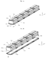
- FIGS. 1A and 1B a perspective view and an exploded perspective view of a battery pack according to an embodiment are illustrated.
- FIG. 2 a cross-sectional view taken along the line 2-2 of FIG. 1A is illustrated.
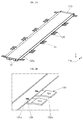
- FIGS. 3A and 3B a perspective view and a partially enlarged view of a cooling plate and a bracket in the battery pack of FIG. 1A are illustrated.
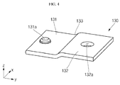
- FIG. 4 an enlarged perspective view of a bracket in the battery pack of FIG. 1A is illustrated.
- FIGS. 1A to 4 a battery pack 100 according to an embodiment will be described with reference to FIGS. 1A to 4 .
- the battery pack 100 includes a plurality of battery modules 110, a plate-shaped cooling plate 120 (having a top surface 120a on which the plurality of battery modules 110 are mounted), at least one bracket 130 (on at least one side of the cooling plate 120), and an external plate 140 covering or on a bottom surface 120b of the cooling plate 120.
- the top surface 120a may face inwardly.
- Each of the plurality of battery modules 110 includes a plurality of rechargeable secondary battery cells 111, a battery protection circuit to control charging and discharging of the plurality of battery cells 111, and a housing 112 to protect the plurality of battery cells 111 and the battery protection circuit.
- the plurality of battery modules 110 are mounted on the top surface 120a of the cooling plate 120 in this embodiment.
- the bottom surface 110b of each of the plurality of battery modules 110 may contact, e.g., may directly contact, the top surface 120a of the cooling plate 120, so that the heat generated during charging and discharging of the plurality of battery cells 111 may be cooled and/or dissipated by the cooling plate 120.
- the plurality of battery modules 110 may be arranged on the top surface 120a of the cooling plate 120 in a lengthwise direction x of the cooling plate 120.
- the plurality of battery modules 110 on the top surface 120a of the cooling plate 120 may include, e.g., five, battery modules 110 arranged in a line.
- the number of battery modules 110 may vary according to a width and length of the cooling plate 120.
- Each of the plurality of battery modules 110 may include fixing parts 112a protruding at opposite sides thereof in a widthwise direction y of the cooling plate 120, e.g., perpendicular to the lengthwise direction x of the cooling plate 120.
- the fixing parts 112a of each of the plurality of battery modules 110 may be in the form of plate-shaped protrusions protruding in parallel or coplanar with the bottom surface 110b of the battery modules 110.
- the fixing parts 112a may be provided at opposite ends of bottom corners of both lengthwise (x) sidewalls 110b of each of the plurality of battery modules 110.
- the fixing parts 112a provided at opposite ends of bottom corners of lengthwise (x) sidewalls of each of the plurality of battery modules 110 may be located to correspond to each other, e.g., may be aligned with one another with respect to central axis running in the x direction.
- each of the plurality of battery modules 110 may include four plate-shaped fixing parts 112a (protruding in the widthwise direction y) from each of the bottom corners of both lengthwise (x) sidewalls 110b.
- each of the fixing parts 112a may include a through-hole 112b passing through a region between the top and bottom surfaces thereof.
- the cooling plate 120 may be plate-shaped and may have a first surface (top surface) 120a and a second surface (bottom surface) 120b.
- the cooling plate 120 may have a rectangular plate shape extending furrier in a first (lengthwise) direction than a second (widthwise) direction.
- the plurality of battery modules 110 may be mounted on the top surface 120a of the cooling plate 120.
- the bottom surface 120b of the cooling plate 120 may be entirely covered by the external plate 140.
- the cooling plate 120 may be interposed between each of the plurality of battery modules 110 and the external plate 140.
- the cooling plate 120 may include a coolant circulating route 122 in an internal space between the top surface 120a and the bottom surface 120b thereof.
- the cooling plate 120 may include a coolant entrance 121 on the widthwise (y) surface to introduce or discharge a coolant to or from the coolant circulating route 122.
- the cooling plate 120 may be made of, e.g., aluminum, and may have high heat transfer and cooling efficiency.
- the cooling plate 120 may include a coolant circulation path therein, and a cooling medium may be provided to the coolant circulation path via a coolant inlet/outlet at an end or ends of the cooling plate 120.
- the cooling plate 120 may further include stoppers 123 along both lengthwise (x) sides thereof.
- Each stopper 123 may be provided on the bottom surface 120b of the cooling plate 120.
- Each stopper 123 may protrude downwardly from the bottom surface 120b of the cooling plate 120 and may be bent and extended in a widthwise direction y.
- the stoppers 123 may be provided on both lengthwise (x) sides of the cooling plate 120, and may protrude from the bottom surface 120b of the cooling plate 120 to then be outwardly bent in the widthwise direction y.
- the stoppers 123 may be provided at regions adjacent to both lengthwise (x) sides of the cooling plate 120.
- the stopper 123 may help prevent one side region 131 of the bracket 130 from moving, e.g., in a height direction z and/or the widthwise direction y of the cooling plate 120.
- At least one bracket 130 may be interposed between the bottom surface 120b of the cooling plate 120 and the stopper 123.
- the stopper 123 may extend downwardly and outwardly relative to the bottom surface 120b of the cooling plate 120 such that a portion of an end of the bracket 130 is on or surrounded by the stopper 123 and the bottom surface 120b of the cooling plate 120.
- brackets 130 may be mounted along both lengthwise (x) sides of the cooling plate 120.
- fixing holes 124 may further be provided in the cooling plate 120 at regions adjacent to both lengthwise (x) sides of the cooling plate 120.
- the fixing holes 124 may pass through the region between the top and bottom surfaces 120a and 120b of the cooling plate 120.
- the fixing hole 124 of the cooling plate 120 may be located to correspond to the at least one bracket 130, and a fixing protrusion 131a (on a top surface 130a of one side region 131 of the bracket 130) may be inserted into the fixing hole 124 to then fix a position of the bracket 130.
- the fixing hole 124 may help prevent the bracket 130 from moving in the lengthwise direction x.
- the cooling plate 120 may fix a position of the bracket 130 with the stoppers 123 and the fixing holes 124.
- the cooling plate 120 may be formed in a single body through extrusion molding, e.g., may have a one-piece, integrally formed structure.
- Brackets 130 may be mounted on both lengthwise (x) sides of the cooling plate 120.
- the bracket 130 may have a plate shape.
- One side region 131 of the bracket 130 may be mounted on or coupled with the cooling plate 120 and another side region 132 of the bracket 130 may be coupled with the fixing part 112a of a battery module 110.
- the bracket 130 may further include a connecting part 133 connecting the one side region 131 and the other side region 132.
- the connecting part 133 may be bent to have or provide a step between the one side region 131 and the other side region 132.
- the one side region 131 and the other side region 132 may be parallel to each other, and/or the connecting part 133 may create a difference in heights (in the z direction) between top and bottom surfaces of the connecting part 133.
- the bracket 130 may be plate- shaped, and the one side region 131, the other side region 132, and the connecting part 133 may be formed in a single body, e.g., may have a one-piece, integrally formed structure.
- the one side region 131 of the bracket 130 may be interposed between the bottom surface 120b of the cooling plate 120 and the stopper 123.
- a top surface 130a of the one side region 131 of the bracket 130 may be brought into contact with the bottom surface 120b of the cooling plate 120 and a bottom surface 130b of the one side region 131 of the bracket 130 may be brought into contact with the stopper 123.
- a portion or end or the one side region of the bracket 130 may be on or at least partially surrounded by the stopper 123 and the bottom surface 120b of the cooling plate 120.
- the one side region 131 of the bracket 130 may further include the fixing protrusion 131a upwardly protruding from the top surface 130a thereof.
- the fixing protrusion 131a may be shaped and sized to correspond to, complement, or fit into the fixing hole 124 of the cooling plate 120.
- the fixing protrusion 131a may be inserted into the fixing hole 124 of the cooling plate 120.
- the bracket 130 may be mounted on, coupled with, and/or otherwise fixed to the cooling plate 120.
- the one side region 131 of the bracket 130 may be interposed between the bottom surface 120b of the cooling plate 120 and the stopper 123, and the fixing protrusion 131a may be inserted into the fixing hole 124 of the cooling plate 120 to then be fixed or coupled thereto.
- the fixing hole 124 and the fixing protrusion 131a may be used to initially and/or temporarily fix the bracket 130 on the cooling plate 120.
- the bracket 130 and the cooling plate 120 may be coupled to each other by, e.g., resistance welding.
- the top surface 130a of the one side region 131 of the bracket 130 and the bottom surface 120b of the cooling plate 120 may be brought into surface-to-surface contact with each other and coupled by welding.
- the fixing hole 124 and the fixing protrusion 131a may be engaged with each other to then initially and/or temporarily fix the bracket 130 on the cooling plate 120, and movement or changing the position of the bracket 130 before the bracket 130 is welded to the cooling plate 120 may be prevented.
- the bracket 130 and the cooling plate 120 may be welded to each other in a state in which their positions are fixed by the stopper 123, the fixing hole 124, and the fixing protrusion 131a, and it need not be necessary to separately fix the cooling plate 120 and the bracket 130 using fixing jigs during welding. It is possible to help prevent the bracket 130 from moving or changing position prior to welding.
- a through-hole 132a (passing through a region between the top surface 10a and the bottom surface 130b of the bracket 130) may be provided at the other side region 132 or end of the bracket 130.
- the through-hole 132a may be shaped and sized to correspond to the through-hole 112b provided in the fixing part 112 of the plurality of battery modules 110, e.g, may have the same size and shape as, and may be aligned with, the through-hole 112b of the fixing part 112.
- the other side region 132 of the bracket 130 may be interposed between the fixing part 112 of a battery module 110 and the external plate 140.
- the through-hole 132a at the other side region 132 of the bracket 130 and the through-hole 112a of each of the plurality of battery modules 110 may be positioned on the same line, e.g., may be vertically (in the z direction) aligned with one another.
- the top surface 130a of the one side region 131 of the bracket 130 may be brought into contact with the bottom surface of the fixing part 112a of a battery module 110, and the bottom surface 130b of the other side region 132 of the bracket 130 may be brought into contact with a top surface of the external plate 140.
- the bracket 130 may be mounted or provided at a region or position corresponding to a region or position of the cooling plate 120 from or at which the fixing part 112a of each of the plurality of battery modules 110 protrude.
- the external plate 140 may be mounted on or may underlie the plurality of battery modules 110 to entirely cover the bottom surface 120a of the cooling plate 120, on which the bracket 130 is mounted.
- the cooling plate 120 and the bracket 130 may be interposed between the plurality of battery modules 110 and the external plate 140.
- the external plate 140 may include a through-hole 141 passing through a region between the top and bottom surfaces of the external plate 140 along or at both lengthwise (x) sides.
- the through-hole 141 of the external plate 140 may have the same shape and size as those of the through-hole 132a provided in the other side region 132 of the bracket 130.
- the through-hole 141 of the external plate 140, the through-hole 132a of the bracket 130 and the through-hole 112b of the battery module 110 may be positioned on the same line, e.g., may be vertically aligned with one another.
- fixing members may be inserted into the through-hole 141 of the external plate 140, the through-hole 132a of the bracket 130, and the through-hole 112b of the battery module 110, thereby coupling the external plate 140, the bracket 130, and the battery module 110 to one another.
- the plurality of battery modules 110 and the external plate 140 mounted on the top surface 120a of the cooling plate 120 may be simultaneously coupled to each other by the fixing members inserted into the through holes 112b, 132a and 141.
- embodiments of the invention can provide a battery pack, comprising a cooling plate; a plurality of battery modules, the plurality of battery modules being mounted on a top surface (first surface) of the cooling plate; and at least one bracket on one lengthwise side of the cooling plate.
- the cooling plate may be longer in the lengthwise direction (first direction) than the widthwise direction (second direction).
- the plurality of battery modules may be arranged along the lengthwise direction of the cooling plate.
- the battery pack may comprise a plurality of brackets, with the brackets extending in a widthwise direction (second direction).
- the brackets may be arranged in pairs, extending in opposite widthwise directions.
- a stopper may be provided on a bottom surface (second surface) of the cooling late for each bracket.
- Each battery module may comprise a first fixing part extending in the widthwise direction (second direction) and a second fixing part extending in an opposite widthwise direction, each fixing part being arranged to be coupled with a bracket.
- An external plate may be provided to cover a bottom surface of the cooling plate.
- the cooling plate, the brackets, and the fixing parts may be interposed between the plurality of battery modules and the external plate.
- a secondary battery pack of an electric vehicle or a hybrid vehicle may include a plurality of battery modules each including a plurality of secondary batteries.
- Such a high-capacity battery pack may include a cooling unit for cooling the batteries during charging and discharging.
- the embodiments may provide a battery pack, in which a bracket and a cooling plate may be reliably and/or consistently welded without a fixing jig.
- the bracket may be temporarily fixed at an accurate position by using a stopper and fixing holes in the cooling plate. Accordingly, an undesirable change in the position of the bracket during welding may be prevented.
Landscapes
- Chemical & Material Sciences (AREA)
- Chemical Kinetics & Catalysis (AREA)
- Electrochemistry (AREA)
- General Chemical & Material Sciences (AREA)
- Engineering & Computer Science (AREA)
- Manufacturing & Machinery (AREA)
- Secondary Cells (AREA)
- Battery Mounting, Suspending (AREA)
Abstract
Description
- In general, unlike a primary battery that cannot be recharged, a secondary battery is a battery that can be charged and discharged. According to technological development and increased production of mobile devices such as mobile phones, notebook computers, or the like, there are rapidly increasing demands for secondary batteries as energy sources. Recently, as alternative energy sources for replacing fossil fuels, secondary batteries for use in electric vehicles or hybrid vehicles are being actively researched and developed.
- Embodiments are directed to a battery pack.
- The embodiments may be realized by providing a battery pack including a plate-shaped cooling plate; a plurality of battery modules, the plurality of battery modules being mounted on a top surface of the cooling plate; and at least one bracket on one lengthwise side of the cooling plate.
- The cooling plate may further include a stopper on a bottom surface thereof at the one lengthwise side of the cooling plate.
- The stopper may downwardly protrude from the bottom surface of the cooling plate and may be bent and extended to the outside of the cooling plate in a widthwise direction of the cooling plate.
- The stopper and the bottom surface of the cooling plate may be on one side region of the bracket.
- The one side region of the bracket may include a fixing protrusion upwardly protruding therefrom, one side of the cooling plate may include a fixing hole passing through a region between top and bottom surfaces of the cooling plate, and the fixing protrusion may be inserted into the at least one fixing hole to couple the bracket with the cooling plate.
- The cooling plate and the bracket may be coupled to each other by welding a contact surface between the bottom surface of the cooling plate and a top surface of the one side region of the bracket.
- The battery pack may further include at least one other bracket on another lengthwise side of the cooling plate, the other lengthwise side of the cooling plate being parallel to the one lengthwise side of the cooling plate.
- The at least one bracket on the one lengthwise side of the cooling plate and the at least one other bracket on the other lengthwise side of the cooling plate may be positioned to be aligned with each other.
- The battery pack may further include an external plate covering a bottom surface of the cooling plate.
- The cooling plate and the at least one bracket on the cooling plate may be interposed between the plurality of battery modules and the external plate.
- According to an aspect of the invention, there is provided a battery pack as set out in claim 1. Preferred features are set out in
claims 2 to 14. - Features will be apparent to those of skill in the art by describing in detail exemplary embodiments with reference to the attached drawings in which:
-
FIGS. 1A and 1B illustrate a perspective view and an exploded perspective view of a battery pack according to an embodiment; -
FIG. 2 illustrates a cross-sectional view taken along the line 2-2 ofFIG. 1A ; -
FIGS. 3A and 3B illustrate a perspective view and a partially enlarged view of a cooling plate and a bracket in the battery pack ofFIG. 1A ; and -
FIG. 4 illustrates an enlarged perspective view of a bracket in the battery pack ofFIG.1A . - Example embodiments will now be described more fully hereinafter with reference to the accompanying drawings; however, they may be embodied in different forms and should not be construed as limited to the embodiments set forth herein. Rather, these embodiments are provided so that this disclosure will be thorough and complete, and will fully convey exemplary implementations to those skilled in the art.
- In the drawing figures, the dimensions of layers and regions may be exaggerated for clarity of illustration. It will also be understood that when a layer or element is referred to as being "on" another layer or substrate, it can be directly on the other layer or substrate, or intervening layers may also be present. In addition, it will also be understood that when a layer is referred to as being "between" two layers, it can be the only layer between the two layers, or one or more intervening layers may also be present. Like reference numerals refer to like elements throughout.
- Furthermore, references to "top" and "bottom" of a component should be interpreted in a way that does not refer to a specific orientation of the component. For example, a "top surface" of a component can refer to a first surface of the component, and a "bottom surface" of that component may refer to a second surface of the component that is opposite to the first surface.
- Referring to
FIGS. 1A and 1B , a perspective view and an exploded perspective view of a battery pack according to an embodiment are illustrated. Referring toFIG. 2 , a cross-sectional view taken along the line 2-2 ofFIG. 1A is illustrated. Referring toFIGS. 3A and 3B , a perspective view and a partially enlarged view of a cooling plate and a bracket in the battery pack ofFIG. 1A are illustrated. Referring toFIG. 4 , an enlarged perspective view of a bracket in the battery pack ofFIG. 1A is illustrated. - Hereinafter, a battery pack 100 according to an embodiment will be described with reference to
FIGS. 1A to 4 . - As illustrated in
FIGS. 1A to 3B , the battery pack 100 includes a plurality ofbattery modules 110, a plate-shaped cooling plate 120 (having atop surface 120a on which the plurality ofbattery modules 110 are mounted), at least one bracket 130 (on at least one side of the cooling plate 120), and anexternal plate 140 covering or on abottom surface 120b of thecooling plate 120. Thetop surface 120a may face inwardly. - Each of the plurality of
battery modules 110 includes a plurality of rechargeablesecondary battery cells 111, a battery protection circuit to control charging and discharging of the plurality ofbattery cells 111, and ahousing 112 to protect the plurality ofbattery cells 111 and the battery protection circuit. The plurality ofbattery modules 110 are mounted on thetop surface 120a of thecooling plate 120 in this embodiment. Thebottom surface 110b of each of the plurality ofbattery modules 110 may contact, e.g., may directly contact, thetop surface 120a of thecooling plate 120, so that the heat generated during charging and discharging of the plurality ofbattery cells 111 may be cooled and/or dissipated by thecooling plate 120. - The plurality of
battery modules 110 may be arranged on thetop surface 120a of thecooling plate 120 in a lengthwise direction x of thecooling plate 120. In an implementation, the plurality ofbattery modules 110 on thetop surface 120a of thecooling plate 120 may include, e.g., five,battery modules 110 arranged in a line. In an implementation, the number ofbattery modules 110 may vary according to a width and length of thecooling plate 120. - Each of the plurality of
battery modules 110 may includefixing parts 112a protruding at opposite sides thereof in a widthwise direction y of thecooling plate 120, e.g., perpendicular to the lengthwise direction x of thecooling plate 120. Thefixing parts 112a of each of the plurality ofbattery modules 110 may be in the form of plate-shaped protrusions protruding in parallel or coplanar with thebottom surface 110b of thebattery modules 110. - In the plurality of
battery modules 110, thefixing parts 112a may be provided at opposite ends of bottom corners of both lengthwise (x)sidewalls 110b of each of the plurality ofbattery modules 110. In an implementation, thefixing parts 112a provided at opposite ends of bottom corners of lengthwise (x) sidewalls of each of the plurality ofbattery modules 110 may be located to correspond to each other, e.g., may be aligned with one another with respect to central axis running in the x direction. For example, each of the plurality ofbattery modules 110 may include four plate-shaped fixing parts 112a (protruding in the widthwise direction y) from each of the bottom corners of both lengthwise (x)sidewalls 110b. In an implementation, each of thefixing parts 112a may include a through-hole 112b passing through a region between the top and bottom surfaces thereof. - The
cooling plate 120 may be plate-shaped and may have a first surface (top surface) 120a and a second surface (bottom surface) 120b. For example, thecooling plate 120 may have a rectangular plate shape extending furrier in a first (lengthwise) direction than a second (widthwise) direction. - For example, it may be assumed that a surface having a larger length when laterally viewed is a lengthwise (x) surface and a surface having a smaller length when laterally viewed and perpendicular to the lengthwise (x) surface is a widthwise (y) surface. The plurality of
battery modules 110 may be mounted on thetop surface 120a of thecooling plate 120. In an implementation, thebottom surface 120b of thecooling plate 120 may be entirely covered by theexternal plate 140. For example, thecooling plate 120 may be interposed between each of the plurality ofbattery modules 110 and theexternal plate 140. - The
cooling plate 120 may include acoolant circulating route 122 in an internal space between thetop surface 120a and thebottom surface 120b thereof. In an implementation, thecooling plate 120 may include acoolant entrance 121 on the widthwise (y) surface to introduce or discharge a coolant to or from thecoolant circulating route 122. Thecooling plate 120 may be made of, e.g., aluminum, and may have high heat transfer and cooling efficiency. For example, thecooling plate 120 may include a coolant circulation path therein, and a cooling medium may be provided to the coolant circulation path via a coolant inlet/outlet at an end or ends of thecooling plate 120. - The
cooling plate 120 may further includestoppers 123 along both lengthwise (x) sides thereof. Eachstopper 123 may be provided on thebottom surface 120b of thecooling plate 120. Eachstopper 123 may protrude downwardly from thebottom surface 120b of thecooling plate 120 and may be bent and extended in a widthwise direction y. For example, thestoppers 123 may be provided on both lengthwise (x) sides of thecooling plate 120, and may protrude from thebottom surface 120b of thecooling plate 120 to then be outwardly bent in the widthwise direction y. Thestoppers 123 may be provided at regions adjacent to both lengthwise (x) sides of thecooling plate 120. Thestopper 123 may help prevent oneside region 131 of thebracket 130 from moving, e.g., in a height direction z and/or the widthwise direction y of thecooling plate 120. At least onebracket 130 may be interposed between thebottom surface 120b of thecooling plate 120 and thestopper 123. For example, thestopper 123 may extend downwardly and outwardly relative to thebottom surface 120b of thecooling plate 120 such that a portion of an end of thebracket 130 is on or surrounded by thestopper 123 and thebottom surface 120b of thecooling plate 120. In an implementation,brackets 130 may be mounted along both lengthwise (x) sides of thecooling plate 120. - In an implementation, fixing holes 124 (to fix a position of the bracket 130) may further be provided in the
cooling plate 120 at regions adjacent to both lengthwise (x) sides of thecooling plate 120. The fixing holes 124 may pass through the region between the top andbottom surfaces cooling plate 120. The fixinghole 124 of thecooling plate 120 may be located to correspond to the at least onebracket 130, and a fixingprotrusion 131a (on atop surface 130a of oneside region 131 of the bracket 130) may be inserted into the fixinghole 124 to then fix a position of thebracket 130. The fixinghole 124 may help prevent thebracket 130 from moving in the lengthwise direction x. For example, thecooling plate 120 may fix a position of thebracket 130 with thestoppers 123 and the fixing holes 124. Thecooling plate 120 may be formed in a single body through extrusion molding, e.g., may have a one-piece, integrally formed structure. -
Brackets 130 may be mounted on both lengthwise (x) sides of thecooling plate 120. Thebracket 130 may have a plate shape. Oneside region 131 of thebracket 130 may be mounted on or coupled with thecooling plate 120 and anotherside region 132 of thebracket 130 may be coupled with the fixingpart 112a of abattery module 110. - The
bracket 130 may further include a connectingpart 133 connecting the oneside region 131 and theother side region 132. The connectingpart 133 may be bent to have or provide a step between the oneside region 131 and theother side region 132. For example, the oneside region 131 and theother side region 132 may be parallel to each other, and/or the connectingpart 133 may create a difference in heights (in the z direction) between top and bottom surfaces of the connectingpart 133. Thebracket 130 may be plate- shaped, and the oneside region 131, theother side region 132, and the connectingpart 133 may be formed in a single body, e.g., may have a one-piece, integrally formed structure. - The one
side region 131 of thebracket 130 may be interposed between thebottom surface 120b of thecooling plate 120 and thestopper 123. For example, atop surface 130a of the oneside region 131 of thebracket 130 may be brought into contact with thebottom surface 120b of thecooling plate 120 and abottom surface 130b of the oneside region 131 of thebracket 130 may be brought into contact with thestopper 123. For example, a portion or end or the one side region of thebracket 130 may be on or at least partially surrounded by thestopper 123 and thebottom surface 120b of thecooling plate 120. - The one
side region 131 of thebracket 130 may further include the fixingprotrusion 131a upwardly protruding from thetop surface 130a thereof. The fixingprotrusion 131a may be shaped and sized to correspond to, complement, or fit into the fixinghole 124 of thecooling plate 120. The fixingprotrusion 131a may be inserted into the fixinghole 124 of thecooling plate 120. As a result of the inserting of the fixingprotrusion 131a of thebracket 130 into the fixinghole 124 of thecooling plate 120, thebracket 130 may be mounted on, coupled with, and/or otherwise fixed to thecooling plate 120. For example, the oneside region 131 of thebracket 130 may be interposed between thebottom surface 120b of thecooling plate 120 and thestopper 123, and the fixingprotrusion 131a may be inserted into the fixinghole 124 of thecooling plate 120 to then be fixed or coupled thereto. - The fixing
hole 124 and the fixingprotrusion 131a may be used to initially and/or temporarily fix thebracket 130 on thecooling plate 120. After thebracket 130 is mounted on thecooling plate 120, thebracket 130 and thecooling plate 120 may be coupled to each other by, e.g., resistance welding. For example, thetop surface 130a of the oneside region 131 of thebracket 130 and thebottom surface 120b of thecooling plate 120 may be brought into surface-to-surface contact with each other and coupled by welding. In an implementation, the fixinghole 124 and the fixingprotrusion 131a may be engaged with each other to then initially and/or temporarily fix thebracket 130 on thecooling plate 120, and movement or changing the position of thebracket 130 before thebracket 130 is welded to thecooling plate 120 may be prevented. For example, thebracket 130 and thecooling plate 120 may be welded to each other in a state in which their positions are fixed by thestopper 123, the fixinghole 124, and the fixingprotrusion 131a, and it need not be necessary to separately fix thecooling plate 120 and thebracket 130 using fixing jigs during welding. It is possible to help prevent thebracket 130 from moving or changing position prior to welding. - A through-
hole 132a (passing through a region between the top surface 10a and thebottom surface 130b of the bracket 130) may be provided at theother side region 132 or end of thebracket 130. The through-hole 132a may be shaped and sized to correspond to the through-hole 112b provided in the fixingpart 112 of the plurality ofbattery modules 110, e.g, may have the same size and shape as, and may be aligned with, the through-hole 112b of the fixingpart 112. Theother side region 132 of thebracket 130 may be interposed between the fixingpart 112 of abattery module 110 and theexternal plate 140. The through-hole 132a at theother side region 132 of thebracket 130 and the through-hole 112a of each of the plurality ofbattery modules 110 may be positioned on the same line, e.g., may be vertically (in the z direction) aligned with one another. - The
top surface 130a of the oneside region 131 of thebracket 130 may be brought into contact with the bottom surface of the fixingpart 112a of abattery module 110, and thebottom surface 130b of theother side region 132 of thebracket 130 may be brought into contact with a top surface of theexternal plate 140. For example, thebracket 130 may be mounted or provided at a region or position corresponding to a region or position of thecooling plate 120 from or at which the fixingpart 112a of each of the plurality ofbattery modules 110 protrude. - The
external plate 140 may be mounted on or may underlie the plurality ofbattery modules 110 to entirely cover thebottom surface 120a of thecooling plate 120, on which thebracket 130 is mounted. For example, thecooling plate 120 and thebracket 130 may be interposed between the plurality ofbattery modules 110 and theexternal plate 140. Theexternal plate 140 may include a through-hole 141 passing through a region between the top and bottom surfaces of theexternal plate 140 along or at both lengthwise (x) sides. The through-hole 141 of theexternal plate 140 may have the same shape and size as those of the through-hole 132a provided in theother side region 132 of thebracket 130. In an implementation, the through-hole 141 of theexternal plate 140, the through-hole 132a of thebracket 130 and the through-hole 112b of thebattery module 110 may be positioned on the same line, e.g., may be vertically aligned with one another. In an implementation, fixing members may be inserted into the through-hole 141 of theexternal plate 140, the through-hole 132a of thebracket 130, and the through-hole 112b of thebattery module 110, thereby coupling theexternal plate 140, thebracket 130, and thebattery module 110 to one another. - For example, the plurality of
battery modules 110 and theexternal plate 140 mounted on thetop surface 120a of thecooling plate 120 may be simultaneously coupled to each other by the fixing members inserted into the throughholes - As discussed, embodiments of the invention can provide a battery pack, comprising a cooling plate; a plurality of battery modules, the plurality of battery modules being mounted on a top surface (first surface) of the cooling plate; and at least one bracket on one lengthwise side of the cooling plate. The cooling plate may be longer in the lengthwise direction (first direction) than the widthwise direction (second direction).
- The plurality of battery modules may be arranged along the lengthwise direction of the cooling plate.
- The battery pack may comprise a plurality of brackets, with the brackets extending in a widthwise direction (second direction). The brackets may be arranged in pairs, extending in opposite widthwise directions.
- A stopper may be provided on a bottom surface (second surface) of the cooling late for each bracket.
- Each battery module may comprise a first fixing part extending in the widthwise direction (second direction) and a second fixing part extending in an opposite widthwise direction, each fixing part being arranged to be coupled with a bracket.
- An external plate may be provided to cover a bottom surface of the cooling plate. The cooling plate, the brackets, and the fixing parts may be interposed between the plurality of battery modules and the external plate.
- By way of summation and review, a secondary battery pack of an electric vehicle or a hybrid vehicle may include a plurality of battery modules each including a plurality of secondary batteries. Such a high-capacity battery pack may include a cooling unit for cooling the batteries during charging and discharging.
- The embodiments may provide a battery pack, in which a bracket and a cooling plate may be reliably and/or consistently welded without a fixing jig. For example, the bracket may be temporarily fixed at an accurate position by using a stopper and fixing holes in the cooling plate. Accordingly, an undesirable change in the position of the bracket during welding may be prevented.
- Example embodiments have been disclosed herein, and although specific terms are employed, they are used and are to be interpreted in a generic and descriptive sense only and not for purpose of limitation. In some instances, as would be apparent to one of ordinary skill in the art as of the filing of the present application, features, characteristics, and/or elements described in connection with a particular embodiment may be used singly or in combination with features, characteristics, and/or elements described in connection with other embodiments unless otherwise specifically indicated. Accordingly, it will be understood by those of skill in the art that various changes in form and details may be made without departing from the scope of the present invention as set forth in the following claims.
Claims (14)
- A battery pack, comprising:a cooling plate;a plurality of battery modules, the plurality of battery modules being mounted on a top surface of the cooling plate; andat least one bracket on one lengthwise side of the cooling plate.
- The battery pack as claimed in claim 1, wherein the cooling plate further includes a stopper on a bottom surface thereof at the one lengthwise side of the cooling plate.
- The battery pack as claimed in claim 2, wherein the stopper downwardly protrudes from the bottom surface of the cooling plate and is bent and extended to the outside of the cooling plate in a widthwise direction of the cooling plate.
- The battery pack as claimed in claim 2 or 3, wherein the stopper and the bottom surface of the cooling plate are on one side region of the bracket.
- The battery pack as claimed in claim 4, wherein:the one side region of the bracket includes a fixing protrusion upwardly protruding therefrom,one side of the cooling plate includes a fixing hole passing through a region between top and bottom surfaces of the cooling plate, andthe fixing protrusion is inserted into the at least one fixing hole to couple the bracket with the cooling plate.
- The battery pack as claimed in claim 5, wherein the cooling plate and the bracket are coupled to each other by welding a contact surface between the bottom surface of the cooling plate and a top surface of the one side region of the bracket.
- The battery pack as claimed in any one of claims 1 to 6, further comprising at least one other bracket on another lengthwise side of the cooling plate, the other lengthwise side of the cooling plate being parallel to the one lengthwise side of the cooling plate.
- The battery pack as claimed in claim 7, wherein the at least one bracket on the one lengthwise side of the cooling plate and the at least one other bracket on the other lengthwise side of the cooling plate are positioned to be aligned with each other.
- The battery pack as claimed in any one of claims 1 to 8, further comprising an external plate covering a bottom surface of the cooling plate.
- The battery pack as claimed in claim 9, wherein the cooling plate and the at least one bracket on the cooling plate are interposed between the plurality of battery modules and the external plate.
- The battery pack as claimed in any one of claims 1 to 10, comprising a plurality of said brackets, each brackets extending in a widthwise direction of a lengthwise side of the cooling plate.
- The battery pack as claimed in claim 11, wherein the brackets are arranged in pairs, with each bracket in a pair of said brackets extending in opposite widthwise directions.
- The battery pack as claimed in any one of claims 1 to 12, wherein each battery module comprises a fixing part arranged to be coupled with a said bracket.
- The battery pack as claimed in any one of claims 1 to 13, wherein each battery module comprises a first fixing part extending in a widthwise direction and a second fixing part extending in an opposite widthwise direction, each fixing part arranged to be coupled with a said bracket.
Applications Claiming Priority (1)
| Application Number | Priority Date | Filing Date | Title |
|---|---|---|---|
| KR1020150033081A KR102288543B1 (en) | 2015-03-10 | 2015-03-10 | Battery pack |
Publications (2)
| Publication Number | Publication Date |
|---|---|
| EP3067962A1 true EP3067962A1 (en) | 2016-09-14 |
| EP3067962B1 EP3067962B1 (en) | 2019-01-02 |
Family
ID=55521636
Family Applications (1)
| Application Number | Title | Priority Date | Filing Date |
|---|---|---|---|
| EP16159706.7A Active EP3067962B1 (en) | 2015-03-10 | 2016-03-10 | Battery pack |
Country Status (4)
| Country | Link |
|---|---|
| US (1) | US10170808B2 (en) |
| EP (1) | EP3067962B1 (en) |
| KR (1) | KR102288543B1 (en) |
| CN (1) | CN105977581B (en) |
Cited By (2)
| Publication number | Priority date | Publication date | Assignee | Title |
|---|---|---|---|---|
| CN113036288A (en) * | 2021-03-04 | 2021-06-25 | 中国第一汽车股份有限公司 | Battery box, power battery system and electric vehicle |
| WO2024246156A1 (en) * | 2023-05-31 | 2024-12-05 | Kautex Textron Gmbh & Co. Kg | Cooling device for installation into a battery housing, battery housing for accommodating at least one battery component, battery having a battery housing |
Families Citing this family (8)
| Publication number | Priority date | Publication date | Assignee | Title |
|---|---|---|---|---|
| DE102016118753A1 (en) * | 2016-10-04 | 2018-04-05 | Johnson Controls Advanced Power Solutions Gmbh | ENERGY STORAGE SYSTEM |
| KR102258175B1 (en) * | 2016-10-25 | 2021-05-28 | 주식회사 엘지에너지솔루션 | Battery Pack with means for cooling heat element |
| CN106898842A (en) * | 2017-03-20 | 2017-06-27 | 乐视汽车(北京)有限公司 | Battery cooling plate and its manufacture method |
| CN111211373B (en) * | 2018-11-21 | 2021-03-30 | 郑州深澜动力科技有限公司 | Liquid cooling plate and manufacturing method thereof |
| KR102412403B1 (en) | 2018-12-26 | 2022-06-22 | 주식회사 엘지에너지솔루션 | Battery module, battery pack comprising the battery module and vehicle comprising the battery pack |
| JP7058613B2 (en) * | 2019-01-15 | 2022-04-22 | 本田技研工業株式会社 | Battery pack |
| KR20210125850A (en) | 2020-04-09 | 2021-10-19 | 주식회사 엘지에너지솔루션 | Battery pack and device including the same |
| WO2023288029A1 (en) * | 2021-07-14 | 2023-01-19 | Our Next Energy, Inc. | Structural cell to pack battery |
Citations (5)
| Publication number | Priority date | Publication date | Assignee | Title |
|---|---|---|---|---|
| DE102010012993A1 (en) * | 2010-03-26 | 2011-09-29 | Daimler Ag | Battery for e.g. electrical vehicle, has set of single cells secured at heat guide plate by attachment members i.e. rivets, where attachment members and framework of single cells are formed as common mold part |
| US20120107663A1 (en) * | 2010-10-29 | 2012-05-03 | Dana Canada Corporation | Heat Exchanger and Battery Unit Structure for Cooling Thermally Conductive Batteries |
| US20130149582A1 (en) * | 2011-12-09 | 2013-06-13 | Honda Motor Co., Ltd. | Battery cooling structure |
| JP2013246990A (en) * | 2012-05-25 | 2013-12-09 | Sanyo Electric Co Ltd | Power supply device, and vehicle and power storage device having this power supply device |
| JP2014093242A (en) * | 2012-11-06 | 2014-05-19 | Nissan Motor Co Ltd | Battery unit |
Family Cites Families (14)
| Publication number | Priority date | Publication date | Assignee | Title |
|---|---|---|---|---|
| JP4601291B2 (en) | 2003-12-26 | 2010-12-22 | 三洋電機株式会社 | Battery pack for vehicles |
| KR100570688B1 (en) | 2004-05-11 | 2006-04-12 | 삼성에스디아이 주식회사 | Stack for Fuel Cell and Fuel Cell Device Having the Stack |
| JP2008192551A (en) | 2007-02-07 | 2008-08-21 | Toyota Motor Corp | Battery pack structure |
| JP2010287514A (en) | 2009-06-12 | 2010-12-24 | Sanyo Electric Co Ltd | Power supply device, and vehicle equipped with this |
| DE102009030016A1 (en) * | 2009-06-23 | 2010-12-30 | Bayerische Motoren Werke Aktiengesellschaft | Device for powering a motor vehicle with a radiator block |
| EP2325922B1 (en) * | 2009-11-19 | 2012-05-09 | SB LiMotive Co., Ltd. | Battery pack |
| JP2011222419A (en) | 2010-04-13 | 2011-11-04 | Sanyo Electric Co Ltd | Battery system and vehicle on which battery system is mounted |
| JP2013025982A (en) | 2011-07-20 | 2013-02-04 | Sanyo Electric Co Ltd | Power supply device and vehicle with power supply device |
| JP2013084444A (en) | 2011-10-08 | 2013-05-09 | Sanyo Electric Co Ltd | Electric power supply apparatus and vehicle including the same |
| JP2013171746A (en) | 2012-02-21 | 2013-09-02 | Sanyo Electric Co Ltd | Power supply device, and vehicle and power storage device having the same |
| JP5878048B2 (en) | 2012-03-16 | 2016-03-08 | 本田技研工業株式会社 | Battery unit |
| KR101669114B1 (en) * | 2012-04-30 | 2016-10-25 | 삼성에스디아이 주식회사 | Battery pack having modulization structure |
| JP6020903B2 (en) * | 2012-10-24 | 2016-11-02 | 株式会社オートネットワーク技術研究所 | Power storage module |
| KR101781923B1 (en) * | 2013-02-05 | 2017-09-26 | 한온시스템 주식회사 | Battery cooler for vehicle |
-
2015
- 2015-03-10 KR KR1020150033081A patent/KR102288543B1/en active Active
-
2016
- 2016-03-04 US US15/060,651 patent/US10170808B2/en active Active
- 2016-03-10 CN CN201610134996.4A patent/CN105977581B/en active Active
- 2016-03-10 EP EP16159706.7A patent/EP3067962B1/en active Active
Patent Citations (5)
| Publication number | Priority date | Publication date | Assignee | Title |
|---|---|---|---|---|
| DE102010012993A1 (en) * | 2010-03-26 | 2011-09-29 | Daimler Ag | Battery for e.g. electrical vehicle, has set of single cells secured at heat guide plate by attachment members i.e. rivets, where attachment members and framework of single cells are formed as common mold part |
| US20120107663A1 (en) * | 2010-10-29 | 2012-05-03 | Dana Canada Corporation | Heat Exchanger and Battery Unit Structure for Cooling Thermally Conductive Batteries |
| US20130149582A1 (en) * | 2011-12-09 | 2013-06-13 | Honda Motor Co., Ltd. | Battery cooling structure |
| JP2013246990A (en) * | 2012-05-25 | 2013-12-09 | Sanyo Electric Co Ltd | Power supply device, and vehicle and power storage device having this power supply device |
| JP2014093242A (en) * | 2012-11-06 | 2014-05-19 | Nissan Motor Co Ltd | Battery unit |
Cited By (3)
| Publication number | Priority date | Publication date | Assignee | Title |
|---|---|---|---|---|
| CN113036288A (en) * | 2021-03-04 | 2021-06-25 | 中国第一汽车股份有限公司 | Battery box, power battery system and electric vehicle |
| CN113036288B (en) * | 2021-03-04 | 2022-03-08 | 中国第一汽车股份有限公司 | Battery box, power battery system and electric vehicle |
| WO2024246156A1 (en) * | 2023-05-31 | 2024-12-05 | Kautex Textron Gmbh & Co. Kg | Cooling device for installation into a battery housing, battery housing for accommodating at least one battery component, battery having a battery housing |
Also Published As
| Publication number | Publication date |
|---|---|
| EP3067962B1 (en) | 2019-01-02 |
| KR20160109155A (en) | 2016-09-21 |
| CN105977581B (en) | 2020-07-03 |
| CN105977581A (en) | 2016-09-28 |
| US20160268656A1 (en) | 2016-09-15 |
| US10170808B2 (en) | 2019-01-01 |
| KR102288543B1 (en) | 2021-08-11 |
Similar Documents
| Publication | Publication Date | Title |
|---|---|---|
| EP3067962B1 (en) | Battery pack | |
| US12021209B2 (en) | Secondary battery module | |
| CN107438911B (en) | Battery module with improved fastening structure | |
| KR102120118B1 (en) | Battery module | |
| JP7335048B2 (en) | Battery module that can prevent gas transfer to adjacent modules | |
| CN107112461B (en) | Battery module including case with clip | |
| EP3467903B1 (en) | Battery pack | |
| CN110100351A (en) | Battery pack including heat transfer medium having louver blade shape | |
| EP2654101A1 (en) | Battery pack | |
| KR20160148398A (en) | Cell Cover for secondary battery and battery module including the same | |
| US12542312B2 (en) | Eco-friendly power source such as a battery module for a transportation vehicle | |
| CN113812039A (en) | Battery pack with enhanced short circuit prevention and shock protection structure | |
| KR20160087093A (en) | Cartridge Having Fixing Bracket and Battery Module and Pack Including the Same | |
| US20130171477A1 (en) | Battery pack | |
| KR102857278B1 (en) | Battery Pack Having High Energy Density And High-Efficiency of radiating heat | |
| KR102341403B1 (en) | Battery module | |
| KR102884059B1 (en) | Battery pack for vehicle | |
| US20260100477A1 (en) | Battery module, and battery pack and vehicle including same | |
| EP4651286A1 (en) | Battery module, and battery pack and vehicle including same | |
| KR102864717B1 (en) | Battery module including end plate assembly | |
| EP4475308A1 (en) | Battery pack and vehicle comprising same | |
| US20240405395A1 (en) | Battery module | |
| JP2026503307A (en) | Battery module and battery pack including same | |
| KR20250125880A (en) | Battery assembly and battery pack including the same | |
| KR20260001308A (en) | Battery pack having cell edge cooling structure and device including the same |
Legal Events
| Date | Code | Title | Description |
|---|---|---|---|
| PUAI | Public reference made under article 153(3) epc to a published international application that has entered the european phase |
Free format text: ORIGINAL CODE: 0009012 |
|
| AK | Designated contracting states |
Kind code of ref document: A1 Designated state(s): AL AT BE BG CH CY CZ DE DK EE ES FI FR GB GR HR HU IE IS IT LI LT LU LV MC MK MT NL NO PL PT RO RS SE SI SK SM TR |
|
| AX | Request for extension of the european patent |
Extension state: BA ME |
|
| STAA | Information on the status of an ep patent application or granted ep patent |
Free format text: STATUS: REQUEST FOR EXAMINATION WAS MADE |
|
| 17P | Request for examination filed |
Effective date: 20170314 |
|
| RBV | Designated contracting states (corrected) |
Designated state(s): AL AT BE BG CH CY CZ DE DK EE ES FI FR GB GR HR HU IE IS IT LI LT LU LV MC MK MT NL NO PL PT RO RS SE SI SK SM TR |
|
| STAA | Information on the status of an ep patent application or granted ep patent |
Free format text: STATUS: EXAMINATION IS IN PROGRESS |
|
| 17Q | First examination report despatched |
Effective date: 20180212 |
|
| GRAP | Despatch of communication of intention to grant a patent |
Free format text: ORIGINAL CODE: EPIDOSNIGR1 |
|
| STAA | Information on the status of an ep patent application or granted ep patent |
Free format text: STATUS: GRANT OF PATENT IS INTENDED |
|
| RIC1 | Information provided on ipc code assigned before grant |
Ipc: H01M 10/613 20140101ALI20180910BHEP Ipc: H01M 10/6554 20140101ALI20180910BHEP Ipc: H01M 2/10 20060101AFI20180910BHEP |
|
| INTG | Intention to grant announced |
Effective date: 20181009 |
|
| GRAS | Grant fee paid |
Free format text: ORIGINAL CODE: EPIDOSNIGR3 |
|
| GRAA | (expected) grant |
Free format text: ORIGINAL CODE: 0009210 |
|
| STAA | Information on the status of an ep patent application or granted ep patent |
Free format text: STATUS: THE PATENT HAS BEEN GRANTED |
|
| AK | Designated contracting states |
Kind code of ref document: B1 Designated state(s): AL AT BE BG CH CY CZ DE DK EE ES FI FR GB GR HR HU IE IS IT LI LT LU LV MC MK MT NL NO PL PT RO RS SE SI SK SM TR |
|
| REG | Reference to a national code |
Ref country code: GB Ref legal event code: FG4D |
|
| REG | Reference to a national code |
Ref country code: CH Ref legal event code: EP Ref country code: AT Ref legal event code: REF Ref document number: 1085514 Country of ref document: AT Kind code of ref document: T Effective date: 20190115 |
|
| REG | Reference to a national code |
Ref country code: IE Ref legal event code: FG4D |
|
| REG | Reference to a national code |
Ref country code: DE Ref legal event code: R096 Ref document number: 602016008833 Country of ref document: DE |
|
| REG | Reference to a national code |
Ref country code: NL Ref legal event code: MP Effective date: 20190102 |
|
| REG | Reference to a national code |
Ref country code: LT Ref legal event code: MG4D |
|
| REG | Reference to a national code |
Ref country code: AT Ref legal event code: MK05 Ref document number: 1085514 Country of ref document: AT Kind code of ref document: T Effective date: 20190102 |
|
| PG25 | Lapsed in a contracting state [announced via postgrant information from national office to epo] |
Ref country code: NL Free format text: LAPSE BECAUSE OF FAILURE TO SUBMIT A TRANSLATION OF THE DESCRIPTION OR TO PAY THE FEE WITHIN THE PRESCRIBED TIME-LIMIT Effective date: 20190102 |
|
| PG25 | Lapsed in a contracting state [announced via postgrant information from national office to epo] |
Ref country code: PL Free format text: LAPSE BECAUSE OF FAILURE TO SUBMIT A TRANSLATION OF THE DESCRIPTION OR TO PAY THE FEE WITHIN THE PRESCRIBED TIME-LIMIT Effective date: 20190102 Ref country code: SE Free format text: LAPSE BECAUSE OF FAILURE TO SUBMIT A TRANSLATION OF THE DESCRIPTION OR TO PAY THE FEE WITHIN THE PRESCRIBED TIME-LIMIT Effective date: 20190102 Ref country code: FI Free format text: LAPSE BECAUSE OF FAILURE TO SUBMIT A TRANSLATION OF THE DESCRIPTION OR TO PAY THE FEE WITHIN THE PRESCRIBED TIME-LIMIT Effective date: 20190102 Ref country code: PT Free format text: LAPSE BECAUSE OF FAILURE TO SUBMIT A TRANSLATION OF THE DESCRIPTION OR TO PAY THE FEE WITHIN THE PRESCRIBED TIME-LIMIT Effective date: 20190502 Ref country code: NO Free format text: LAPSE BECAUSE OF FAILURE TO SUBMIT A TRANSLATION OF THE DESCRIPTION OR TO PAY THE FEE WITHIN THE PRESCRIBED TIME-LIMIT Effective date: 20190402 Ref country code: ES Free format text: LAPSE BECAUSE OF FAILURE TO SUBMIT A TRANSLATION OF THE DESCRIPTION OR TO PAY THE FEE WITHIN THE PRESCRIBED TIME-LIMIT Effective date: 20190102 Ref country code: LT Free format text: LAPSE BECAUSE OF FAILURE TO SUBMIT A TRANSLATION OF THE DESCRIPTION OR TO PAY THE FEE WITHIN THE PRESCRIBED TIME-LIMIT Effective date: 20190102 |
|
| PG25 | Lapsed in a contracting state [announced via postgrant information from national office to epo] |
Ref country code: IS Free format text: LAPSE BECAUSE OF FAILURE TO SUBMIT A TRANSLATION OF THE DESCRIPTION OR TO PAY THE FEE WITHIN THE PRESCRIBED TIME-LIMIT Effective date: 20190502 Ref country code: HR Free format text: LAPSE BECAUSE OF FAILURE TO SUBMIT A TRANSLATION OF THE DESCRIPTION OR TO PAY THE FEE WITHIN THE PRESCRIBED TIME-LIMIT Effective date: 20190102 Ref country code: GR Free format text: LAPSE BECAUSE OF FAILURE TO SUBMIT A TRANSLATION OF THE DESCRIPTION OR TO PAY THE FEE WITHIN THE PRESCRIBED TIME-LIMIT Effective date: 20190403 Ref country code: LV Free format text: LAPSE BECAUSE OF FAILURE TO SUBMIT A TRANSLATION OF THE DESCRIPTION OR TO PAY THE FEE WITHIN THE PRESCRIBED TIME-LIMIT Effective date: 20190102 Ref country code: BG Free format text: LAPSE BECAUSE OF FAILURE TO SUBMIT A TRANSLATION OF THE DESCRIPTION OR TO PAY THE FEE WITHIN THE PRESCRIBED TIME-LIMIT Effective date: 20190402 Ref country code: RS Free format text: LAPSE BECAUSE OF FAILURE TO SUBMIT A TRANSLATION OF THE DESCRIPTION OR TO PAY THE FEE WITHIN THE PRESCRIBED TIME-LIMIT Effective date: 20190102 |
|
| REG | Reference to a national code |
Ref country code: DE Ref legal event code: R097 Ref document number: 602016008833 Country of ref document: DE |
|
| PG25 | Lapsed in a contracting state [announced via postgrant information from national office to epo] |
Ref country code: AL Free format text: LAPSE BECAUSE OF FAILURE TO SUBMIT A TRANSLATION OF THE DESCRIPTION OR TO PAY THE FEE WITHIN THE PRESCRIBED TIME-LIMIT Effective date: 20190102 Ref country code: MC Free format text: LAPSE BECAUSE OF FAILURE TO SUBMIT A TRANSLATION OF THE DESCRIPTION OR TO PAY THE FEE WITHIN THE PRESCRIBED TIME-LIMIT Effective date: 20190102 Ref country code: DK Free format text: LAPSE BECAUSE OF FAILURE TO SUBMIT A TRANSLATION OF THE DESCRIPTION OR TO PAY THE FEE WITHIN THE PRESCRIBED TIME-LIMIT Effective date: 20190102 Ref country code: CZ Free format text: LAPSE BECAUSE OF FAILURE TO SUBMIT A TRANSLATION OF THE DESCRIPTION OR TO PAY THE FEE WITHIN THE PRESCRIBED TIME-LIMIT Effective date: 20190102 Ref country code: AT Free format text: LAPSE BECAUSE OF FAILURE TO SUBMIT A TRANSLATION OF THE DESCRIPTION OR TO PAY THE FEE WITHIN THE PRESCRIBED TIME-LIMIT Effective date: 20190102 Ref country code: RO Free format text: LAPSE BECAUSE OF FAILURE TO SUBMIT A TRANSLATION OF THE DESCRIPTION OR TO PAY THE FEE WITHIN THE PRESCRIBED TIME-LIMIT Effective date: 20190102 Ref country code: IT Free format text: LAPSE BECAUSE OF FAILURE TO SUBMIT A TRANSLATION OF THE DESCRIPTION OR TO PAY THE FEE WITHIN THE PRESCRIBED TIME-LIMIT Effective date: 20190102 Ref country code: EE Free format text: LAPSE BECAUSE OF FAILURE TO SUBMIT A TRANSLATION OF THE DESCRIPTION OR TO PAY THE FEE WITHIN THE PRESCRIBED TIME-LIMIT Effective date: 20190102 Ref country code: SK Free format text: LAPSE BECAUSE OF FAILURE TO SUBMIT A TRANSLATION OF THE DESCRIPTION OR TO PAY THE FEE WITHIN THE PRESCRIBED TIME-LIMIT Effective date: 20190102 |
|
| REG | Reference to a national code |
Ref country code: CH Ref legal event code: PL |
|
| PLBE | No opposition filed within time limit |
Free format text: ORIGINAL CODE: 0009261 |
|
| STAA | Information on the status of an ep patent application or granted ep patent |
Free format text: STATUS: NO OPPOSITION FILED WITHIN TIME LIMIT |
|
| PG25 | Lapsed in a contracting state [announced via postgrant information from national office to epo] |
Ref country code: LU Free format text: LAPSE BECAUSE OF NON-PAYMENT OF DUE FEES Effective date: 20190310 Ref country code: SM Free format text: LAPSE BECAUSE OF FAILURE TO SUBMIT A TRANSLATION OF THE DESCRIPTION OR TO PAY THE FEE WITHIN THE PRESCRIBED TIME-LIMIT Effective date: 20190102 |
|
| 26N | No opposition filed |
Effective date: 20191003 |
|
| REG | Reference to a national code |
Ref country code: BE Ref legal event code: MM Effective date: 20190331 |
|
| PG25 | Lapsed in a contracting state [announced via postgrant information from national office to epo] |
Ref country code: LI Free format text: LAPSE BECAUSE OF NON-PAYMENT OF DUE FEES Effective date: 20190331 Ref country code: CH Free format text: LAPSE BECAUSE OF NON-PAYMENT OF DUE FEES Effective date: 20190331 Ref country code: IE Free format text: LAPSE BECAUSE OF NON-PAYMENT OF DUE FEES Effective date: 20190310 |
|
| PG25 | Lapsed in a contracting state [announced via postgrant information from national office to epo] |
Ref country code: SI Free format text: LAPSE BECAUSE OF FAILURE TO SUBMIT A TRANSLATION OF THE DESCRIPTION OR TO PAY THE FEE WITHIN THE PRESCRIBED TIME-LIMIT Effective date: 20190102 Ref country code: BE Free format text: LAPSE BECAUSE OF NON-PAYMENT OF DUE FEES Effective date: 20190331 |
|
| PG25 | Lapsed in a contracting state [announced via postgrant information from national office to epo] |
Ref country code: TR Free format text: LAPSE BECAUSE OF FAILURE TO SUBMIT A TRANSLATION OF THE DESCRIPTION OR TO PAY THE FEE WITHIN THE PRESCRIBED TIME-LIMIT Effective date: 20190102 |
|
| PG25 | Lapsed in a contracting state [announced via postgrant information from national office to epo] |
Ref country code: MT Free format text: LAPSE BECAUSE OF NON-PAYMENT OF DUE FEES Effective date: 20190310 |
|
| REG | Reference to a national code |
Ref country code: DE Ref legal event code: R079 Ref document number: 602016008833 Country of ref document: DE Free format text: PREVIOUS MAIN CLASS: H01M0002100000 Ipc: H01M0050200000 |
|
| PG25 | Lapsed in a contracting state [announced via postgrant information from national office to epo] |
Ref country code: CY Free format text: LAPSE BECAUSE OF FAILURE TO SUBMIT A TRANSLATION OF THE DESCRIPTION OR TO PAY THE FEE WITHIN THE PRESCRIBED TIME-LIMIT Effective date: 20190102 |
|
| PG25 | Lapsed in a contracting state [announced via postgrant information from national office to epo] |
Ref country code: HU Free format text: LAPSE BECAUSE OF FAILURE TO SUBMIT A TRANSLATION OF THE DESCRIPTION OR TO PAY THE FEE WITHIN THE PRESCRIBED TIME-LIMIT; INVALID AB INITIO Effective date: 20160310 |
|
| PG25 | Lapsed in a contracting state [announced via postgrant information from national office to epo] |
Ref country code: MK Free format text: LAPSE BECAUSE OF FAILURE TO SUBMIT A TRANSLATION OF THE DESCRIPTION OR TO PAY THE FEE WITHIN THE PRESCRIBED TIME-LIMIT Effective date: 20190102 |
|
| P01 | Opt-out of the competence of the unified patent court (upc) registered |
Effective date: 20230528 |
|
| PGFP | Annual fee paid to national office [announced via postgrant information from national office to epo] |
Ref country code: GB Payment date: 20260303 Year of fee payment: 11 |
|
| PGFP | Annual fee paid to national office [announced via postgrant information from national office to epo] |
Ref country code: DE Payment date: 20260305 Year of fee payment: 11 |
|
| PGFP | Annual fee paid to national office [announced via postgrant information from national office to epo] |
Ref country code: FR Payment date: 20260309 Year of fee payment: 11 |