EP3067961A1 - Battery module - Google Patents
Battery module Download PDFInfo
- Publication number
- EP3067961A1 EP3067961A1 EP16159593.9A EP16159593A EP3067961A1 EP 3067961 A1 EP3067961 A1 EP 3067961A1 EP 16159593 A EP16159593 A EP 16159593A EP 3067961 A1 EP3067961 A1 EP 3067961A1
- Authority
- EP
- European Patent Office
- Prior art keywords
- wire
- voltage
- metal band
- stacked body
- battery module
- Prior art date
- Legal status (The legal status is an assumption and is not a legal conclusion. Google has not performed a legal analysis and makes no representation as to the accuracy of the status listed.)
- Granted
Links
Images




Classifications
-
- H—ELECTRICITY
- H01—ELECTRIC ELEMENTS
- H01M—PROCESSES OR MEANS, e.g. BATTERIES, FOR THE DIRECT CONVERSION OF CHEMICAL ENERGY INTO ELECTRICAL ENERGY
- H01M10/00—Secondary cells; Manufacture thereof
- H01M10/04—Construction or manufacture in general
- H01M10/0468—Compression means for stacks of electrodes and separators
-
- H—ELECTRICITY
- H01—ELECTRIC ELEMENTS
- H01M—PROCESSES OR MEANS, e.g. BATTERIES, FOR THE DIRECT CONVERSION OF CHEMICAL ENERGY INTO ELECTRICAL ENERGY
- H01M10/00—Secondary cells; Manufacture thereof
- H01M10/42—Methods or arrangements for servicing or maintenance of secondary cells or secondary half-cells
- H01M10/48—Accumulators combined with arrangements for measuring, testing or indicating the condition of cells, e.g. the level or density of the electrolyte
- H01M10/482—Accumulators combined with arrangements for measuring, testing or indicating the condition of cells, e.g. the level or density of the electrolyte for several batteries or cells simultaneously or sequentially
-
- H—ELECTRICITY
- H01—ELECTRIC ELEMENTS
- H01M—PROCESSES OR MEANS, e.g. BATTERIES, FOR THE DIRECT CONVERSION OF CHEMICAL ENERGY INTO ELECTRICAL ENERGY
- H01M10/00—Secondary cells; Manufacture thereof
- H01M10/42—Methods or arrangements for servicing or maintenance of secondary cells or secondary half-cells
- H01M10/425—Structural combination with electronic components, e.g. electronic circuits integrated to the outside of the casing
-
- H—ELECTRICITY
- H01—ELECTRIC ELEMENTS
- H01M—PROCESSES OR MEANS, e.g. BATTERIES, FOR THE DIRECT CONVERSION OF CHEMICAL ENERGY INTO ELECTRICAL ENERGY
- H01M10/00—Secondary cells; Manufacture thereof
- H01M10/42—Methods or arrangements for servicing or maintenance of secondary cells or secondary half-cells
- H01M10/48—Accumulators combined with arrangements for measuring, testing or indicating the condition of cells, e.g. the level or density of the electrolyte
- H01M10/486—Accumulators combined with arrangements for measuring, testing or indicating the condition of cells, e.g. the level or density of the electrolyte for measuring temperature
-
- H—ELECTRICITY
- H01—ELECTRIC ELEMENTS
- H01M—PROCESSES OR MEANS, e.g. BATTERIES, FOR THE DIRECT CONVERSION OF CHEMICAL ENERGY INTO ELECTRICAL ENERGY
- H01M50/00—Constructional details or processes of manufacture of the non-active parts of electrochemical cells other than fuel cells, e.g. hybrid cells
- H01M50/10—Primary casings; Jackets or wrappings
- H01M50/102—Primary casings; Jackets or wrappings characterised by their shape or physical structure
- H01M50/103—Primary casings; Jackets or wrappings characterised by their shape or physical structure prismatic or rectangular
-
- H—ELECTRICITY
- H01—ELECTRIC ELEMENTS
- H01M—PROCESSES OR MEANS, e.g. BATTERIES, FOR THE DIRECT CONVERSION OF CHEMICAL ENERGY INTO ELECTRICAL ENERGY
- H01M50/00—Constructional details or processes of manufacture of the non-active parts of electrochemical cells other than fuel cells, e.g. hybrid cells
- H01M50/20—Mountings; Secondary casings or frames; Racks, modules or packs; Suspension devices; Shock absorbers; Transport or carrying devices; Holders
- H01M50/204—Racks, modules or packs for multiple batteries or multiple cells
- H01M50/207—Racks, modules or packs for multiple batteries or multiple cells characterised by their shape
- H01M50/209—Racks, modules or packs for multiple batteries or multiple cells characterised by their shape adapted for prismatic or rectangular cells
-
- H—ELECTRICITY
- H01—ELECTRIC ELEMENTS
- H01M—PROCESSES OR MEANS, e.g. BATTERIES, FOR THE DIRECT CONVERSION OF CHEMICAL ENERGY INTO ELECTRICAL ENERGY
- H01M50/00—Constructional details or processes of manufacture of the non-active parts of electrochemical cells other than fuel cells, e.g. hybrid cells
- H01M50/20—Mountings; Secondary casings or frames; Racks, modules or packs; Suspension devices; Shock absorbers; Transport or carrying devices; Holders
- H01M50/262—Mountings; Secondary casings or frames; Racks, modules or packs; Suspension devices; Shock absorbers; Transport or carrying devices; Holders with fastening means, e.g. locks
- H01M50/264—Mountings; Secondary casings or frames; Racks, modules or packs; Suspension devices; Shock absorbers; Transport or carrying devices; Holders with fastening means, e.g. locks for cells or batteries, e.g. straps, tie rods or peripheral frames
-
- H—ELECTRICITY
- H01—ELECTRIC ELEMENTS
- H01M—PROCESSES OR MEANS, e.g. BATTERIES, FOR THE DIRECT CONVERSION OF CHEMICAL ENERGY INTO ELECTRICAL ENERGY
- H01M50/00—Constructional details or processes of manufacture of the non-active parts of electrochemical cells other than fuel cells, e.g. hybrid cells
- H01M50/20—Mountings; Secondary casings or frames; Racks, modules or packs; Suspension devices; Shock absorbers; Transport or carrying devices; Holders
- H01M50/298—Mountings; Secondary casings or frames; Racks, modules or packs; Suspension devices; Shock absorbers; Transport or carrying devices; Holders characterised by the wiring of battery packs
-
- H—ELECTRICITY
- H01—ELECTRIC ELEMENTS
- H01M—PROCESSES OR MEANS, e.g. BATTERIES, FOR THE DIRECT CONVERSION OF CHEMICAL ENERGY INTO ELECTRICAL ENERGY
- H01M50/00—Constructional details or processes of manufacture of the non-active parts of electrochemical cells other than fuel cells, e.g. hybrid cells
- H01M50/50—Current conducting connections for cells or batteries
- H01M50/569—Constructional details of current conducting connections for detecting conditions inside cells or batteries, e.g. details of voltage sensing terminals
-
- H—ELECTRICITY
- H01—ELECTRIC ELEMENTS
- H01M—PROCESSES OR MEANS, e.g. BATTERIES, FOR THE DIRECT CONVERSION OF CHEMICAL ENERGY INTO ELECTRICAL ENERGY
- H01M2220/00—Batteries for particular applications
- H01M2220/20—Batteries in motive systems, e.g. vehicle, ship, plane
-
- H—ELECTRICITY
- H01—ELECTRIC ELEMENTS
- H01M—PROCESSES OR MEANS, e.g. BATTERIES, FOR THE DIRECT CONVERSION OF CHEMICAL ENERGY INTO ELECTRICAL ENERGY
- H01M50/00—Constructional details or processes of manufacture of the non-active parts of electrochemical cells other than fuel cells, e.g. hybrid cells
- H01M50/50—Current conducting connections for cells or batteries
- H01M50/502—Interconnectors for connecting terminals of adjacent batteries; Interconnectors for connecting cells outside a battery casing
- H01M50/505—Interconnectors for connecting terminals of adjacent batteries; Interconnectors for connecting cells outside a battery casing comprising a single busbar
-
- Y—GENERAL TAGGING OF NEW TECHNOLOGICAL DEVELOPMENTS; GENERAL TAGGING OF CROSS-SECTIONAL TECHNOLOGIES SPANNING OVER SEVERAL SECTIONS OF THE IPC; TECHNICAL SUBJECTS COVERED BY FORMER USPC CROSS-REFERENCE ART COLLECTIONS [XRACs] AND DIGESTS
- Y02—TECHNOLOGIES OR APPLICATIONS FOR MITIGATION OR ADAPTATION AGAINST CLIMATE CHANGE
- Y02E—REDUCTION OF GREENHOUSE GAS [GHG] EMISSIONS, RELATED TO ENERGY GENERATION, TRANSMISSION OR DISTRIBUTION
- Y02E60/00—Enabling technologies; Technologies with a potential or indirect contribution to GHG emissions mitigation
- Y02E60/10—Energy storage using batteries
-
- Y—GENERAL TAGGING OF NEW TECHNOLOGICAL DEVELOPMENTS; GENERAL TAGGING OF CROSS-SECTIONAL TECHNOLOGIES SPANNING OVER SEVERAL SECTIONS OF THE IPC; TECHNICAL SUBJECTS COVERED BY FORMER USPC CROSS-REFERENCE ART COLLECTIONS [XRACs] AND DIGESTS
- Y02—TECHNOLOGIES OR APPLICATIONS FOR MITIGATION OR ADAPTATION AGAINST CLIMATE CHANGE
- Y02P—CLIMATE CHANGE MITIGATION TECHNOLOGIES IN THE PRODUCTION OR PROCESSING OF GOODS
- Y02P70/00—Climate change mitigation technologies in the production process for final industrial or consumer products
- Y02P70/50—Manufacturing or production processes characterised by the final manufactured product
Definitions
- the invention relates to a battery module. More particularly, the invention relates to a battery module provided with a voltage sensor.
- Japanese Patent Application Publication JP 2010-40295 A describes a battery module that includes a stacked body formed by an array of a plurality of battery cells, end plates provided one on each end of this stacked body, and restraining bands that restrain the end plates.
- a battery module negative terminals and positive terminals provided on the battery cells are connected together by a bus bar, such that the battery cells are connected together in series. Also, a power line is connected to the battery module, and this power line is connected to a power control unit via a SMR (System Main Relay) or the like.
- SMR System Main Relay
- the battery module is provided with voltage sensors that measure the voltage of each battery cell, a voltage detection line that is connected to each voltage sensor as well as to a battery ECU (Electronic Control Unit), a temperature sensor that measures the temperature at a predetermined location of the stacked body, and a thermistor line that is connected to the temperature sensors as well as to the battery ECU.
- the voltage sensors are typically connected to the negative terminals and the positive terminals of the battery cells.
- the power control unit includes a converter and an inverter.
- the power control unit is electrically connected to a motor. Also, noise generated by the motor, the converter, and the inverter while a vehicle is being driven reaches the battery module via the power line. The noise that has reached the battery module also enters the voltage sensors and the voltage detection line through the terminals of the battery cells.
- the thermistor line is simply distanced from the voltage detection line so that the noise that is superimposed on the thermistor line becomes sufficiently small, the thermistor line would end up being in a position that is also distanced from the battery module, which creates problems for mounting of the battery module.
- a current detection line from a current sensor provided is also provided in addition to the thermistor line, and voltage lower than that of the voltage detection line is applied to this current detection line. If the current detection line is provided close to the voltage detection line, noise from the voltage detection line may also be transmitted to the current detection line.
- the invention thus provides a battery module in which the transmission of noise from a voltage detection line to a thermistor line or a current detection line is inhibited, by a simple structure.
- One aspect of the invention relates to a battery module that includes a stacked body that is electrically connected to a power control unit and includes a plurality of battery cells; a restraint configured to restrain the stacked body, and the restraint including a metal band made of metal that extends from one end of the stacked body to the other end of the stacked body and that is electrically grounded; a voltage sensor that is provided on at least a portion of the plurality of battery cells, and the voltage sensor being configured to detect a voltage of the portion of the plurality of battery cells; a first wire that is connected to the voltage sensor and extends in a stacking direction of the battery cells; a temperature sensor configured to measure a temperature of the stacked body or a current sensor configured to measure a current that flows into and out of the stacked body; and a second wire that is connected to the temperature sensor or the current sensor, and extends in the stacking direction. A voltage lower than that of the first wire is applied to the second wire.
- the metal band is arranged between the first wire and
- the battery module according to this aspect of the invention is therefore able to inhibit noise from the first wire from being transmitted to the second wire, by a simple structure.
- each battery cell may include a case, and an electrode body that is housed inside of the case, wherein a distance between the second wire and the electrode body may be greater than a distance between the first wire and the electrode body.
- the noise transmitted to the electrode body is able to be inhibited from being transmitted to the second wires.
- the stacked body may include two end surfaces and a plurality of peripheral surfaces positioned between the two end surfaces
- the restraint may include a first metal band and a second metal band that arranged spaced apart from each other and extend from the one end to the other end of the stacked body, the first metal band and the second metal band being provided on the same side surface, wherein the second wire may be arranged between the first metal band and the second metal band and the first wire may be arranged closer to an outer peripheral edge portion side of the peripheral side than the first metal band and the second metal band.
- a height of the at least one metal band may be greater than a width of the at least one metal band.
- noise from the first wire is able to be better inhibited from being transmitted to the second wire. Also, by increasing the height, a long distance between the second wire and the electrode body can be ensured, while inhibiting the transmission of noise from the first wire.
- a ratio of a distance between the first wire and the second wire to a distance over which the first wire and the second wire run side-by-side may be smaller than 1 : 4, preferably 1 : 16.
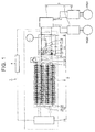
- FIG. 1 is a view showing a frame format of the general structure of a HV system 1.
- the HV system 1 includes a power control unit 3, a battery pack 2 that is electrically connected to the power control unit 3, a battery ECU (Electronic Control Unit) 4 and a first rotary electric machine MG1 and a second rotary electric machine MG2 that are connected to the power control unit 3.
- a power control unit 3 includes a battery pack 2 that is electrically connected to the power control unit 3, a battery ECU (Electronic Control Unit) 4 and a first rotary electric machine MG1 and a second rotary electric machine MG2 that are connected to the power control unit 3.
- a battery ECU Electronic Control Unit
- the power control unit 3 includes a converter 5 that steps up direct-current power supplied from the battery pack 2, a first inverter 6 that is connected to the converter 5 and the first rotary electric machine MG1, and a second inverter 7 that is connected to the converter 5 and the second rotary electric machine MG2.
- the converter 5 and the inverters 6 and 7 include a plurality of elements.
- the first rotary electric machine MG1 and the second rotary electric machine MG2 each include a stator and a rotor, with a stator coil attached to the stator.
- Noise may be generated when the converter 5 is driven or when the first and second inverters 6 and 7 are driven. Also, noise may be generated in the stator coil when the first and second rotary electric machines MG1 and MG2 are driven.
- the battery pack 2 includes a housing case 9, a blower 8 provided inside the housing case 9, a battery unit 10 that is housed in the housing case 9, a positive output line 11 and a negative output line 12 that are connected to the battery unit 10, a junction box 14 to which the positive output line 11 and the negative output line 12 are connected and that is housed inside the housing case 9, a service plug 13, and a battery control portion 15.
- the junction box 14 includes a first SMR (System Main Relay) 16 that is connected to the positive output line 11, a second SMR 17 that is connected to the negative output line 12, a third SMR 18 and a resistor 19 that are provided in parallel with respect to the SMR 17, a current sensor 20 that is provided in the positive output line 11, and a housing case 21.
- SMR System Main Relay
- the current sensor 20 is provided in a portion of the positive output line 11 that is between the SMR 16 and the service plug 13.
- the battery unit 10 includes a battery module 25 and a battery module 26.
- the battery module 25 and the battery module 26 are connected together in series.
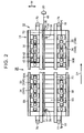
- the battery module 26 includes i) a stacked body 31 that is electrically connected to the power control unit 3 and includes a plurality of battery cells 30, ii) a restraint 32 that restrains this stacked body 31, iii) a voltage sensor 33 that is provided on each battery cell 30, and iv) a wire 34 that is connected to each voltage sensor 33.
- the battery module 26 includes a plurality of temperature sensors 35, a temperature sensor 36 provided near the battery module 26, a wire 37 that is connected to each temperature sensor 35, a wire 38 that is connected to the temperature sensor 36, and a bus bar 39 that electrically connects the battery cells 30 together.
- the stacked body 31 is formed by the plurality of battery cells 30 being stacked in a stacking direction D1.
- a separator that is made of resin may be arranged between adjacent battery cells 30.
- the stacked body 31 is electrically connected to the power control unit 3 via the positive output line 11, the service plug 13, the junction box 14, a power line 22, and the battery module 25, and the like.
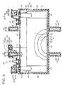
- each of the battery cells 30 includes a case 40, an electrode body 41 that is housed inside of the case 40, external terminals 42 and 43 that are provided on an upper surface of the case 40, a connecting portion 44 that connects the external terminal 42 to the electrode body 41, and a connecting portion 45 that connects the external terminal 43 to the electrode body 41.
- the case 40 includes a box-shaped metal case 46, and a resin frame 47 that is provided on a peripheral surface of this metal case 46.
- the electrode body 41 includes a sheet-like positive electrode 50, a sheet-like separator 51, a sheet-like negative electrode 52, and a sheet-like separator 53, and is formed by rolling the positive electrode 50, the separator 51, the negative electrode 52, and the separator 53 while they are in a stacked state.
- the positive electrode 50 includes a reactive portion where a positive-electrode active material or the like has been applied to a metal foil, and an exposed portion 54 where the positive-electrode active material or the like has not been applied and the metal foil is exposed.
- the negative electrode 52 includes a reactive portion where a negative-electrode active material or the like has been applied to a metal foil, and an exposed portion 55 where the negative-electrode active material or the like has not been applied and the metal foil is exposed.
- the reactive portion of the positive electrode 50 and the reactive portion of the negative electrode 52 are arranged facing one another with the separator 51 or the separator 53 in between.
- the exposed portion 54 of the positive electrode 50 is positioned on one end side of the electrode body 41, and the exposed portion 55 of the negative electrode 52 is positioned on the other end side of the electrode body 41.
- the connecting portion 45 connects the exposed portion 54 to the external terminal 43, and the connecting portion 44 connects the exposed portion 55 to the external terminal 42.
- Electrolyte is filled inside the metal case 46, and the electrode body 41 is arranged immersed in the electrolyte.
- battery cells 30 that are adjacent in the array direction of the battery cells 30 are connected together by the bus bar 39. Adjacent battery cells 30 are connected together in series. More specifically, the external terminal 42 of one battery cell 30 is connected by the bus bar 39 to the external terminal 43 of another battery cell 30 that is adjacent to this battery cell 30.
- the battery cells 30 are arranged such that the external terminal 42 and the external terminal 43 are alternating in the array direction of the battery cells 30.
- the bus bar 39 that connects the battery cells 30 together in series need only connect the external terminal 42 and the external terminal 43 that are adjacent in the array direction of the battery cells 30, so the length of the bus bar 39 is short.
- the stacked body 31 is formed in a generally cuboid shape.
- the stacked body 31 includes an end surface 60 and an end surface 61 positioned one on each end in the array direction of the battery cells 30, and a plurality of peripheral surfaces 62 positioned between the end surface 60 and the end surface 61.
- the plurality of peripheral surfaces 62 are an upper surface 63, a lower surface 64, and side surfaces 65 and 66.
- the restraint 32 includes an end plate 70 provided on the end surface 60 of the stacked body 31, an end plate 71 provided on the end surface 61, a plurality of restraining bands 72, 73, 74, and 75 that connect the end plate 70 to the end plate 71, and a ground portion provided on both ends of the restraining bands.
- the restraining bands 72, 73, 74, and 75 extend from one end of the stacked body 31 to the other end.
- the restraining band 72 and the restraining band 73 are arranged on the upper surface 63 of the battery cells 30, and the restraining band 74 and the restraining band 75 are arranged on the lower surface 64 of the battery cells 30.
- the restraining band 72 and the restraining band 73 are arranged spaced apart from each other in a width direction W on the upper surface 63 of the battery cells 30, and the restraining band 74 and the restraining band 75 are arranged spaced apart from each other in the width direction W on the lower surface 64 of the battery cells 30.
- the restraining band 72 includes a hollow resin frame 80, and a metal band 81 that is inserted into this resin frame 80.
- the restraining bands 73, 74, and 75 are also form the same, and include a hollow resin frame 82, 84, and 86, and a metal band 83, 85, and 87 that is inserted into this resin frame 82, 84, and 86, respectively.
- the metal bands 81, 83, 85, and 87 are arranged extending from one end of the stacked body 31 to the other end.
- a ground portion 77 is connected to one end of the restraining band 73, and a ground portion 78 is connected to the other end of the restraining band 73.
- the ground portion 77 connects the metal band 83 of the restraining band 73 to a body of a vehicle, such that the metal band 83 of the restraining band 73 is grounded.
- the ground portion 78 connects the metal band 83 of the restraining band 73 to the body of the vehicle, such that the metal band 83 of the restraining band 73 is grounded.
- a ground portion 76 is connected to one end of the restraining band 72, and a ground portion 79 shown in FIG. 2 is connected to the other end of the restraining band 72.
- the ground portions 76 and 79 both connect the metal band 81 of the restraining band 72 to the body of the vehicle, such that the metal band 81 is grounded.
- one end of the metal band 87 of the restraining band 75 is connected to the ground portion 77, and the other end of the metal band 87 is connected to the ground portion 78. Also, the metal band 87 of the restraining band 75 is connected to the body of the vehicle. One end of the metal band 85 of the restraining band 74 is connected to the ground portion 76, and the other end of the metal band 85 of the restraining band 74 is connected to the ground portion 79. Then the metal band 85 is grounded to the body of the vehicle.
- the voltage sensor 33 is provided on each battery cell 30.
- the voltage sensor 33 is provided on the external terminal 43 of each battery cell 30.
- the voltage sensor 33 measures the voltage between the external terminal 43 and the external terminal 42 of the battery cell 30 on which the voltage sensor 33 is provided, and detects the cell voltage of the battery cell 30.
- the battery cells 30 are arranged such that the external terminals 42 and the external terminals 43 are arranged alternately in the array direction of the battery cells 30. Therefore, the plurality of voltage sensors 33 include voltage sensors 33A that are arranged on the side surface 65 side of the stacked body 31, and voltage sensors 33B that are arranged on the side surface 66 side of the stacked body 31.
- sensors that are provided in plurality may sometimes be referred to in the singular to simplify the description and facilitate understanding.
- a wire 34A (a first wire) is connected to each voltage sensor 33A, and a wire 34B (a first wire) is connected to each voltage sensor 33B.
- the wires 34A and 34B are covered by resin frames, not shown.
- the wires 34A and the wires 34B are mounted to the battery module 26 so as to extend in the stacking direction D1 of the battery cells 30.
- wires that are provided in plurality may sometimes be referred to in the singular to simplify the description and facilitate understanding.
- the battery module 26 includes a high-voltage wire 90A and a high-voltage wire 90B that are provided on the upper surface 63, and a low-voltage wire 91.
- the restraining band 72 and the restraining band 73 are arranged spaced apart in the width direction W of the stacked body 31, with the restraining band 72 arranged on the side surface 65 side, and the restraining band 73 arranged on the side surface 66 side.
- the high-voltage wire 90A is arranged in a position nearer to the side surface 65 than the restraining band 72, and the high-voltage wire 90B is arranged in a position nearer to the side surface 66 than the restraining band 73. Also, the low-voltage wire 91 is arranged between the restraining band 72 and the restraining band 73.
- the wires 34A that are connected to the voltage sensors 33A are bundled together to form the high-voltage wire 90A.
- the wires 34B that are connected to the voltage sensors 33B are bundled together to form the high-voltage wire 90B.
- the wires 37 (second wires) that are connected to the temperature sensors 35, the wire 38 (a second wire) that is connected to the temperature sensor 36, and a wire 48 that is connected to the current sensor 20 are all bundled together to form the low-voltage wire 91.
- the temperature sensors 35 measure the temperatures of the battery cells 30 on which they are provided, and the temperature sensor 36 measures the temperature around the stacked body 31.
- the wires 37 and the wire 38 are also mounted to the battery module 26 so as to extend in the stacking direction D1 of the battery cells 30.
- the high-voltage wire 90A includes a hollow resin frame 92A and the plurality of wires 34A that are housed in the resin frame 92A
- the high-voltage wire 90B includes a hollow resin frame 92B and the plurality of wires 34B that are housed in the resin frame 92B.
- the low-voltage wire 91 includes a hollow resin frame 93, and a wire bundle 96 that is housed in this resin frame 93.
- the wire bundle 96 includes the wires 37 and 38, and the wire 48.
- the resin frame 93 includes a wire frame 94 that houses the wires 37, 38, and 48, and an engaging portion 95 that is connected to this wire frame 94.
- the engaging portion 95 is engaged with the resin frame 80 of the restraining band 72.
- the metal band 81 of the restraining band 72 is arranged between the low-voltage wire 91 and the high-voltage wire 90A
- the metal band 83 of the restraining band 73 is arranged between the low-voltage wire 91 and the high-voltage wire 90B.
- Voltage of the battery cells 30 is applied to the wires 34A and the wires 34B. This voltage that is applied to the wires 34A and the wires 34B is higher than a voltage that is applied to the wires 37 that are connected to the temperature sensors 35 and the voltage that is applied to the wire 38 that is connected to the temperature sensor 36.
- the voltage that is applied to the wires 34A and the wires 34B is higher voltage than the voltage that is applied to the wire 48 that is connected to the current sensor 20.
- the wires 34A and the wires 34B are connected to the external terminals 43 and the external terminals 42.
- the external terminals 43 and external terminals 42 are connected to the positive output line 11 and the negative output line 12 shown in FIG. 1 , via the bus bars 39 and the like.
- the positive output line 11 and the negative output line 12 are connected to the power control unit 3.
- Noise may be generated when the converter 5 is driven or when the inverters 6 and 7 are driven. Noise may also be generated in the stator coil when the first and second rotary electric machines MG1 and MG2 are driven. This noise travels along the positive output line 11 and the negative output line 12 and reaches the battery pack 2. Also, the noise is transmitted to the wires 34A and 34B via the external terminals 42 and 43.
- the battery control portion 15 is able to accurately ascertain the temperature of the battery cells 30.
- the output value of the wire 48 is also able to be inhibited from oscillating from the noise, so the battery control portion 15 is able to accurately ascertain the value of current that flows into and out of the battery unit 10.
- the grounded metal band 83 is arranged between the low-voltage wire 91 and the high-voltage wire 90B, so even if noise flows to the wire 34B of the support frame 90, the electric field formed by this noise is inhibited from being transmitted to the wires 37, 38, and 48 of the low-voltage wire 91.
- the wires 37, 38, and 48 are arranged between the metal band 81 and the metal band 83 that are arranged spaced apart from each other in the width direction W, and the high-voltage wires 90A and 90B are arranged on the outer peripheral edge portion side of the upper surface 63 (the peripheral surfaces 62), so noise from the high-voltage wires 90A and 90B is able to be inhibited from being superimposed on the wires 37, 38, and 48.
- noise is inhibited from being transmitted to the wires 37 and 38 and the wire 48, but a structure in which noise is inhibited from being transmitted to all of these wires (i.e., the wires 37 and 38 and the wire 48) is not absolutely essential to the invention.
- At least one of i) the wires 37 and 38, and ii) the wire 48, inside the resin frame 93 may be housed in the low-voltage wire 91. If the wires 37 and 38 are housed inside the resin frame 93, the battery unit 10 is able to obtain an accurate temperature. Also, if the wire 48 is housed inside the resin frame 93, the battery unit 10 is able to obtain an accurate current value.
- the voltage sensor 33 is provided on each battery cell 30, but the voltage sensor 33 may also be arranged on a specific battery cell 30.
- the metal band 81 of the restraining band 72 is arranged between the external terminal 43 and the wires 37, 38, and 48, and the metal band 83 of the restraining band 73 is arranged between the external terminal 42 and the low-voltage wire 91.
- the external terminal 43 and the external terminal 42 are connected to the power control unit 3 via the bus bar 39, and the positive output line 11 and the negative output line 12 and the like. Therefore, noise generated by the power control unit 3 is transmitted to the external terminals 42 and 43.
- the grounded metal bands 81 and 83 are arranged between the external terminals 42 and 43 and the wires 37, 38, and 48, so noise transmitted to the external terminals 42 and 43 is inhibited from being transmitted to the wires 37, 38, and 48 of the low-voltage wire 91.
- the distance between the wires 37, 38, and 48 of the low-voltage wire 91 and the electrode body 41 is denoted as distance L1.
- the distance between the wire 34A of the high-voltage wire 90A and the electrode body 41 is denoted as distance LA
- the distance between the wire 34B of the high-voltage wire 90B and the electrode body 41 is denoted as distance LB.
- the distance L1 is the average value of the distance between the wires 37, 38, and 48 and the electrode body 41
- the distance LA is the average value of the distance between each wire 34A and the electrode body 41.
- the distance LB is the average value of the distance between each wire 34B and the electrode body 41.
- the distance L1 is longer than the distances LA and LB.
- noise from the power control unit 3 is also transmitted to the electrode body 41. Because the distance L1 is longer than the distances LA and LB, the noise transmitted to the electrode body 41 is able to be inhibited from being transmitted to the wires 37, 38, and 48.
- a height H of the metal band 81 is greater than a width W1 of the metal band 81.
- the battery module 26 has been described with reference to FIGS. 2 to 4 .
- the battery module 25 has a structure similar to that of the battery module 26.
- FIG. 5 is a plan view showing a frame format of the battery module 25.
- the battery module 25 includes a stacked body 131 formed by an array of a plurality of battery cells 130 in a stacking direction D2, a restraint 132 that restrains the stacked body 131, a voltage sensor 133 provided on the stacked body 131, a plurality of temperature sensors 135 provided on the stacked body 131, and a temperature sensor 136 arranged around the stacked body 131.
- the battery module 25 also includes high-voltage wires 190A and 190B, and a low-voltage wire 191.
- the stacked body 131 is electrically connected to the power control unit 3 via the power line 22 and the negative output line 12 and the like.
- the stacked body 131 is formed in a generally cuboid shape.
- the stacked body 131 includes an end surface 160, an end surface 161, and an upper surface 163 and side surfaces 165 and 166 positioned between the end surface 160 and the end surface 161.
- Each battery cell 130 includes a case 140, and an external terminal 142 and an external terminal 143 that are provided on an upper surface of the case 140.
- the external terminal 142 and the external terminal 143 of adjacent battery cells 130 are connected together by a bus bar 139, such that the battery cells 130 are connected together in series.
- the battery cells 130 are arranged such that the external terminal 142 and the external terminal 143 are arranged alternately in the array direction of the battery cells 130. Therefore, the length of the bus bar 139 is able to be kept short.
- the restraint 132 includes an end plate 170 provided on the end surface 160, an end plate 171 provided on the end surface 161, a restraining band 172 and a restraining band 173, ground portions 176, 177, 178, and 179, and two restraining bands provided on a lower surface of the stacked body 131.
- Each of the restraining bands 172 and 173 includes a hollow resin frame, and a metal band inserted into this resin frame. The metal band of each restraining band 172 and 173 is fastened to the end plate 170 and the end plate 171.
- One end of the metal band of the restraining band 172 is connected to the ground portion 176, and the other end of the restraining band 172 is connected to the ground portion 179. Then, the metal band of the restraining band 172 is grounded to the body of the vehicle by the ground portion 176 and the ground portion 179. Similarly, the metal band of the restraining band 173 is connected to the ground portion 177 and the ground portion 178, and the metal band of the restraining band 173 is grounded to the body of the vehicle by the ground portion 177 and the ground portion 178.
- the restraining band 172 and the restraining band 173 are arranged on the upper surface 163, spaced apart in the width direction of the stacked body 131, with the restraining band 172 arranged on the side surface 165 side, and the restraining band 173 arranged on the side surface 166 side.
- the high-voltage wire 190A and the high-voltage wire 190B are both arranged on the upper surface 163 of the stacked body 131.
- the high-voltage wire 190A is arranged closer to the side surface 165 side of the stacked body 131 than the restraining band 172, and the high-voltage wire 190B is arranged closer to the side surface 166 side than the restraining band 173.
- the voltage sensor 133 is provided on each battery cell 130. Each voltage sensor 133 is connected to the positive-electrode external terminal 143 and the negative-electrode external terminal 142 of the battery cell 130. These voltage sensors 133 measure the voltages of the battery cells 130.
- the voltage sensor 133 is provided on the external terminal 142 of each battery cell 130.
- the plurality of battery cells 130 are arranged such that the external terminal 142 and the external terminal 143 are alternating in the array direction of the battery cells 130. Therefore, the voltage sensor 133 includes a voltage sensor 133A arranged on the side surface 165 side, and a voltage sensor 133B arranged on the side surface 166 side.
- a wire 134A (a first wire) is connected to the voltage sensor 133A
- a wire 134B (a first wire) is connected to the wire 134B.
- the wires 134A are housed bundled with the high-voltage wire 190A
- the wires 134B are housed bundled with the high-voltage wire 190B.
- the wires 134A and the wires 134B are mounted to the battery module 25 so as to extend in the stacking direction D2.
- the low-voltage wire 191 is arranged on the upper surface 163 of the stacked body 131, and is arranged between the restraining band 172 and the restraining band 173.
- a wire 137 is connected to each temperature sensor 135, and the plurality of wires 137 (second wires) are housed inside the low-voltage wire 191.
- a wire 138 (a second wire) is connected to the temperature sensor 136 arranged near the stacked body 131, and this wire 138 is also housed inside the low-voltage wire 191.
- the wire 138 and the wires 137 are also mounted to the battery module 25 so as to extend in the stacking direction D2.
- the voltage applied to the wires 137 and the wire 138 is lower than the voltage applied to the wires 134A and 134B.
- the wires 134A and 134B are connected to the negative output line 12 via the bus bar 139 and the like. Also, noise generated by the power control unit 3 and the like is transmitted to the wires 134A and 134B through the negative output line 12 and the bus bar 139.
- a metal band of the grounded restraining band 173 is arranged between the low-voltage wire 191 inside of which the wires 137 are housed, and the high-voltage wire 190B. Therefore, noise transmitted to the high-voltage wire 190B is able to be inhibited from being transmitted to the wires 137 and 138 of the low-voltage wire 191.
- the grounded restraining band 172 is also arranged between the low-voltage wire 191 and the high-voltage wire 190A, so noise transmitted to the high-voltage wire 190A is able to be inhibited from being transmitted to the wires 137 and 138 of the low-voltage wire 191.
- FIGS. 6 and 7 are graphs showing an electric field distribution of the battery module 26 in a position that is the distance L1 away from the electrode body 41, when the power control unit 3 is being driven. More specifically, FIGS. 6 and 7 are views showing the electric field distribution when an accelerator pedal and a brake pedal are both both depressed, in a Ready_ON state. At this time, at least the converter 5 and the inverter 7 are being driven, and current is also flowing through the stator coil of the second rotary electric machine MG2.
- FIG. 6 is a graph showing the electric field distribution when none of the restraining bands 72, 73, 74, and 75 are grounded.
- FIG. 7 is a graph showing the electric field distribution when all of the restraining bands 72, 73, 74, and 75 are grounded.
- the electric field intensity in regions R1 to R6 increases from region R6 to region R1 in the following order: region R6, region R5, region R4, region R3, region R2, region R1. That is, the region R1 is the region where the electric field intensity is highest. As is evident from FIGS. 6 and 7 , the electric field intensity is lowest all around when all of the restraining bands 72, 73, 74, and 75 are grounded. In particular, it is evident that the electric field intensity of a portion positioned between the restraining band 72 and the restraining band 73 is able to be reduced by grounding the restraining bands 72, 73, 74, and 75.
- the battery module according to the example embodiment will be compared to a battery module according to a comparative example, with reference to FIGS. 8 to 11 .
- FIG. 8 is a plan view showing a frame format of a battery pack 200 according to the comparative example.
- the battery pack 200 includes a battery unit 210, a junction box 214, and a battery control portion 215.
- the battery unit 210 includes a battery module 211 and a battery module 212.
- the battery module 211 and the battery module 212 are connected together in series.
- the battery modules 211 and 212 include stacked bodies 213 and 214, and restrains 220 and 221 that restrain the stacked bodies 213 and 214, respectively.
- the restraint 220 includes restraining bands 222 and 223 that are provided on an upper surface of the stacked body 213, and the restraint 221 includes restraining bands 224 and 225 that are provided on an upper surface of the stacked body 214.
- the battery module 211 includes a voltage sensor provided on each battery cell, a high-voltage line 226 formed by the wires from the voltages sensors being bundled together, a plurality of temperature sensors 230, 231, 232, and 233, and a low-voltage line 235 formed by wires that are connected to the temperature sensors 230, 231, 232, and 233 being bundled together.
- the restraining bands 222 and 223, the high-voltage line 226, and the low-voltage line 235 are all provided on an upper surface of the stacked body 213.
- the restraining band 223 is arranged in a position closer to one side surface of the stacked body 213 than the restraining band 222, and the high-voltage line 226 and the low-voltage line 235 are arranged in positions closer to the one side surface than the restraining band 222.
- the restraining band 223 is not arranged between the high-voltage line 226 and the low-voltage line 235, and the high-voltage line 226 and the low-voltage line 235 are arranged running side-by-side.
- FIG. 9 is a graph illustrating an output value from the temperature sensor 230.
- the horizontal axis represents time
- the vertical axis represents the output value from the temperature sensor 230
- T1 denotes the timing of IG_ON
- T2 denotes the timing of Ready_ON
- T3 denotes the timing at which both the accelerator pedal and the brake pedal start to be depressed.
- FIG. 10 is a plane view showing a frame format of the battery pack 2 according to the example embodiment.
- the temperature sensors 135A, 135B, and 135C shown in FIG. 10 correspond to the temperature sensors 231, 232, and 233 shown in FIG. 8
- the temperature sensor 136 shown in FIG. 10 corresponds to the temperature sensor 230 shown in FIG. 8 .
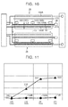
- FIG. 11 is a graph showing a comparison between the amount of oscillation of the output value of the temperature sensors 230, 231, 232, and 233 provided in the battery module 211 according to the comparative example, and the amount of oscillation of the output value of the temperature sensors 136, 135A, 135B, and 135C provided on the battery module 25 according to the example embodiment.
- the broken line indicates the amount of oscillation of the output value of the temperature sensors 230, 231, 232, and 233 in the comparative example. As shown by this broken line, the amount of oscillation of the output value of the temperature sensor 230 is greater than that of the other temperature sensors 231, 232, and 233. More specifically, the amount of oscillation of the output value increases as the distance between the battery control portion 215 and the temperature sensors 230, 231, 232, and 233 becomes longer.
- the reason why the amount of oscillation of the output value increases as the distance between the battery control portion 215 and the temperature sensors 230, 231, 232, and 233 becomes longer in this way is because when the distance between the battery control portion 215 and the temperature sensors 230, 231, 232, and 233 becomes longer, so too does the distance over which the high-voltage line 226 runs side-by-side with the low-voltage line 235, and as a result, the amount of noise transmitted from the high-voltage line 226 increases.
- the solid line indicates the amount of oscillation of the output value of the temperature sensors 136, 135A, 135B, and 135C provided on the battery module 25 according to the example embodiment.
- the amount of oscillation of the output values from the temperature sensors 136, 135A, 135B, and 135C is smaller than the amount of oscillation of the output values from the temperature sensors 230, 231, 232, and 233 of the comparative example.
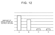
- FIG. 12 is a graph showing a comparison between the range of oscillation of the output values of the temperature sensors 136, 135A, 135B, and 135C provided in the battery module 25 according to the example embodiment, and the range of oscillation of the output values when the distance between the high-voltage line 226 and the low-voltage line 235 is changed in the battery module 211 according to the comparative example.
- a in FIG. 12 represents the average value of the range of oscillation of the output values of the temperature sensors 230, 231, 232, and 233 provided in the battery module 211 according to the comparative example shown in FIG. 8 .
- the high-voltage line 226 and the low-voltage line 235 are close to one another.
- the high-voltage line 226 and the low-voltage line 235 are arranged such that the distance between them is greater than it is in the battery module represented by "A".
- the distance between the high-voltage line 226 and the low-voltage line 235 is a distance L2
- the distance over which the high-voltage line 226 and the low-voltage line 235 run side-by-side is a distance L3
- the ratio of the distance L2 to the distance L3 i.e., L2 : L3
- the high-voltage line 226 and the low-voltage line 235 are arranged such that the distance L2 is greater than it is in the battery module represented by "B".
- the high-voltage line 226 and the low-voltage line 235 are arranged such that the ratio of the distance L2 to the distance L3 (i.e., L2 : L3) is 1 : 4.
- the low-voltage line 235 is unable to be arranged on an upper surface of the stacked body 213.
- “D” represents the battery module 25 according to the example embodiment.
- the distance between the high-voltage wire 190B and the low-voltage wire 191 is a distance L4
- the distance over which the high-voltage wire 190B and the low-voltage wire 191 run side-by-side is a distance L5
- the ratio of the distance L4 to the distance L5 is 1 : 16.
- the range of oscillation of the output value with the battery module 25 according to the example embodiment is able to be reduced to approximately the same level as that with the battery module of "C".
- the distance between the high-voltage wire 190B and the low-voltage wire 191 is close, and both the high-voltage wire 190B and the low-voltage wire 191 are able to be arranged on the upper surface of the battery module. As a result, the battery module 25 is able to be compact.
- oscillation of the output values from the temperature sensors 136, 135A, 135B, and 135C of the battery module 25 is described with reference to FIGS. 11 and 12 and the like, oscillation of the output values from the current sensor 20 is also able to be similarly inhibited from oscillating.
Landscapes
- Chemical & Material Sciences (AREA)
- Chemical Kinetics & Catalysis (AREA)
- Electrochemistry (AREA)
- General Chemical & Material Sciences (AREA)
- Engineering & Computer Science (AREA)
- Manufacturing & Machinery (AREA)
- Microelectronics & Electronic Packaging (AREA)
- Battery Mounting, Suspending (AREA)
- Secondary Cells (AREA)
- Connection Of Batteries Or Terminals (AREA)
Abstract
Description
- The invention relates to a battery module. More particularly, the invention relates to a battery module provided with a voltage sensor.
- Japanese Patent Application Publication
JP 2010-40295 A - In such a battery module, negative terminals and positive terminals provided on the battery cells are connected together by a bus bar, such that the battery cells are connected together in series. Also, a power line is connected to the battery module, and this power line is connected to a power control unit via a SMR (System Main Relay) or the like.
- Further, the battery module is provided with voltage sensors that measure the voltage of each battery cell, a voltage detection line that is connected to each voltage sensor as well as to a battery ECU (Electronic Control Unit), a temperature sensor that measures the temperature at a predetermined location of the stacked body, and a thermistor line that is connected to the temperature sensors as well as to the battery ECU. The voltage sensors are typically connected to the negative terminals and the positive terminals of the battery cells.
- Here, the power control unit includes a converter and an inverter. The power control unit is electrically connected to a motor. Also, noise generated by the motor, the converter, and the inverter while a vehicle is being driven reaches the battery module via the power line. The noise that has reached the battery module also enters the voltage sensors and the voltage detection line through the terminals of the battery cells.
- At this time, if the voltage detection line and the thermistor line are provided in positions close to one another, noise transmitted to the voltage detection line will be transmitted through space to the thermistor line, and as a result, noise will also enter the output of the thermistor line.
- In order to inhibit noise from entering the thermistor line in this way, it is conceivable to connect a filter between the power control unit and the battery module, or increase the distance between the voltage detection line and the thermistor line, for example.
- However, providing a filter would increase the cost. Also, if the thermistor line is simply distanced from the voltage detection line so that the noise that is superimposed on the thermistor line becomes sufficiently small, the thermistor line would end up being in a position that is also distanced from the battery module, which creates problems for mounting of the battery module.
- In the battery module, a current detection line from a current sensor provided is also provided in addition to the thermistor line, and voltage lower than that of the voltage detection line is applied to this current detection line. If the current detection line is provided close to the voltage detection line, noise from the voltage detection line may also be transmitted to the current detection line.
- The invention thus provides a battery module in which the transmission of noise from a voltage detection line to a thermistor line or a current detection line is inhibited, by a simple structure.
- One aspect of the invention relates to a battery module that includes a stacked body that is electrically connected to a power control unit and includes a plurality of battery cells; a restraint configured to restrain the stacked body, and the restraint including a metal band made of metal that extends from one end of the stacked body to the other end of the stacked body and that is electrically grounded; a voltage sensor that is provided on at least a portion of the plurality of battery cells, and the voltage sensor being configured to detect a voltage of the portion of the plurality of battery cells; a first wire that is connected to the voltage sensor and extends in a stacking direction of the battery cells; a temperature sensor configured to measure a temperature of the stacked body or a current sensor configured to measure a current that flows into and out of the stacked body; and a second wire that is connected to the temperature sensor or the current sensor, and extends in the stacking direction. A voltage lower than that of the first wire is applied to the second wire. The metal band is arranged between the first wire and the second wire.
- In this aspect, when noise is generated in a system that is connected to the battery module, that noise is transmitted to the voltage sensor. The noise that is transmitted to the voltage sensor will then be transmitted to the first wire. When the noise reaches the first wire, an electric field from the noise will form around the first wire. However, the electric field formed by the noise is able to be inhibited from reaching the second wire because the grounded metal band is arranged between the first wire and the second wire. As a result, the noise that reached the first wire is able to be inhibited from being transmitted to the second wire.
- The battery module according to this aspect of the invention is therefore able to inhibit noise from the first wire from being transmitted to the second wire, by a simple structure.
- According to an aspect of the invention each battery cell may include a case, and an electrode body that is housed inside of the case, wherein a distance between the second wire and the electrode body may be greater than a distance between the first wire and the electrode body.
- Since the distance between the second wire and the electrode body is greater than a distance between the first wire and the electrode body, the noise transmitted to the electrode body is able to be inhibited from being transmitted to the second wires.
- According to an aspect of the invention the stacked body may include two end surfaces and a plurality of peripheral surfaces positioned between the two end surfaces, and the restraint may include a first metal band and a second metal band that arranged spaced apart from each other and extend from the one end to the other end of the stacked body, the first metal band and the second metal band being provided on the same side surface, wherein the second wire may be arranged between the first metal band and the second metal band and the first wire may be arranged closer to an outer peripheral edge portion side of the peripheral side than the first metal band and the second metal band.
- According to an aspect of the invention, when the at least one metal band is viewed in a sectional view taken along a cross-section that is perpendicular to the direction in which the at least one metal band extends, a height of the at least one metal band may be greater than a width of the at least one metal band.
- In this aspect, by increasing the height of the at least one metal band, noise from the first wire is able to be better inhibited from being transmitted to the second wire. Also, by increasing the height, a long distance between the second wire and the electrode body can be ensured, while inhibiting the transmission of noise from the first wire.
- According to an aspect of the invention a ratio of a distance between the first wire and the second wire to a distance over which the first wire and the second wire run side-by-side may be smaller than 1 : 4, preferably 1 : 16.
- Accordingly, it is possible to make the battery module compact.
- Features, advantages, and technical and industrial significance of exemplary embodiments of the invention will be described below with reference to the accompanying drawings, in which like numerals denote like elements, and wherein:
-
FIG. 1 is a view showing a frame format of the general structure of a HV system; -
FIG. 2 is a plan view showing a frame format of a battery module; -
FIG. 3 is a sectional view of a battery cell; -
FIG. 4 is a perspective view of the battery module; -
FIG. 5 is a plan view showing a frame format of another battery module; -
FIG. 6 is a graph showing the electric field distribution when restraining bands are not grounded; -
FIG. 7 is a graph showing the electric field distribution when restraining bands are grounded; -
FIG. 8 is a plan view showing a frame format of a battery pack according to a comparative example; -
FIG. 9 is a graph showing an output value of a temperature sensor; -
FIG. 10 is a plan view showing a frame format of a battery pack according to the example embodiment; -
FIG. 11 is a graph showing a comparison of the amount of oscillation in the output value of each temperature sensor provided in the battery module according to the comparative example, and the amount of oscillation in the output value of each temperature sensor provided in the battery module according to the example embodiment; and -
FIG. 12 is a graph showing a comparison of the range of oscillation of the output values of the temperature sensors provided in the battery module according to the example embodiment, and the range of oscillation of the output values when the distance between a high-voltage line and a low-voltage line is changed in the battery module according to the comparative example. -
FIG. 1 is a view showing a frame format of the general structure of a HV system 1. As shown inFIG. 1 , the HV system 1 includes apower control unit 3, abattery pack 2 that is electrically connected to thepower control unit 3, a battery ECU (Electronic Control Unit) 4 and a first rotary electric machine MG1 and a second rotary electric machine MG2 that are connected to thepower control unit 3. - The
power control unit 3 includes aconverter 5 that steps up direct-current power supplied from thebattery pack 2, a first inverter 6 that is connected to theconverter 5 and the first rotary electric machine MG1, and asecond inverter 7 that is connected to theconverter 5 and the second rotary electric machine MG2. - The
converter 5 and theinverters 6 and 7 include a plurality of elements. The first rotary electric machine MG1 and the second rotary electric machine MG2 each include a stator and a rotor, with a stator coil attached to the stator. - Noise may be generated when the
converter 5 is driven or when the first andsecond inverters 6 and 7 are driven. Also, noise may be generated in the stator coil when the first and second rotary electric machines MG1 and MG2 are driven. - The
battery pack 2 includes ahousing case 9, ablower 8 provided inside thehousing case 9, abattery unit 10 that is housed in thehousing case 9, apositive output line 11 and anegative output line 12 that are connected to thebattery unit 10, ajunction box 14 to which thepositive output line 11 and thenegative output line 12 are connected and that is housed inside thehousing case 9, a service plug 13, and abattery control portion 15. - The
junction box 14 includes a first SMR (System Main Relay) 16 that is connected to thepositive output line 11, a second SMR 17 that is connected to thenegative output line 12, a third SMR 18 and a resistor 19 that are provided in parallel with respect to the SMR 17, acurrent sensor 20 that is provided in thepositive output line 11, and ahousing case 21. - The
current sensor 20 is provided in a portion of thepositive output line 11 that is between the SMR 16 and the service plug 13. - The
battery unit 10 includes abattery module 25 and abattery module 26. Thebattery module 25 and thebattery module 26 are connected together in series. - In
FIG. 2 , thebattery module 26 includes i) a stackedbody 31 that is electrically connected to thepower control unit 3 and includes a plurality ofbattery cells 30, ii) arestraint 32 that restrains this stackedbody 31, iii) avoltage sensor 33 that is provided on eachbattery cell 30, and iv) awire 34 that is connected to eachvoltage sensor 33. Thebattery module 26 includes a plurality oftemperature sensors 35, a temperature sensor 36 provided near thebattery module 26, awire 37 that is connected to eachtemperature sensor 35, awire 38 that is connected to the temperature sensor 36, and abus bar 39 that electrically connects thebattery cells 30 together. - The
stacked body 31 is formed by the plurality ofbattery cells 30 being stacked in a stacking direction D1. A separator that is made of resin may be arranged betweenadjacent battery cells 30. Thestacked body 31 is electrically connected to thepower control unit 3 via thepositive output line 11, the service plug 13, thejunction box 14, apower line 22, and thebattery module 25, and the like. - As shown in
FIG. 3 , each of thebattery cells 30 includes acase 40, anelectrode body 41 that is housed inside of thecase 40,external terminals case 40, a connectingportion 44 that connects theexternal terminal 42 to theelectrode body 41, and a connectingportion 45 that connects theexternal terminal 43 to theelectrode body 41. - The
case 40 includes a box-shapedmetal case 46, and aresin frame 47 that is provided on a peripheral surface of thismetal case 46. - The
electrode body 41 includes a sheet-likepositive electrode 50, a sheet-like separator 51, a sheet-likenegative electrode 52, and a sheet-like separator 53, and is formed by rolling thepositive electrode 50, theseparator 51, thenegative electrode 52, and theseparator 53 while they are in a stacked state. - The
positive electrode 50 includes a reactive portion where a positive-electrode active material or the like has been applied to a metal foil, and an exposedportion 54 where the positive-electrode active material or the like has not been applied and the metal foil is exposed. Thenegative electrode 52 includes a reactive portion where a negative-electrode active material or the like has been applied to a metal foil, and an exposedportion 55 where the negative-electrode active material or the like has not been applied and the metal foil is exposed. The reactive portion of thepositive electrode 50 and the reactive portion of thenegative electrode 52 are arranged facing one another with theseparator 51 or theseparator 53 in between. - The exposed
portion 54 of thepositive electrode 50 is positioned on one end side of theelectrode body 41, and the exposedportion 55 of thenegative electrode 52 is positioned on the other end side of theelectrode body 41. The connectingportion 45 connects the exposedportion 54 to theexternal terminal 43, and the connectingportion 44 connects the exposedportion 55 to theexternal terminal 42. Electrolyte is filled inside themetal case 46, and theelectrode body 41 is arranged immersed in the electrolyte. - In
FIG. 2 ,battery cells 30 that are adjacent in the array direction of thebattery cells 30 are connected together by thebus bar 39.Adjacent battery cells 30 are connected together in series. More specifically, theexternal terminal 42 of onebattery cell 30 is connected by thebus bar 39 to theexternal terminal 43 of anotherbattery cell 30 that is adjacent to thisbattery cell 30. - In the example shown in
FIG. 2 , thebattery cells 30 are arranged such that theexternal terminal 42 and theexternal terminal 43 are alternating in the array direction of thebattery cells 30. As a result, thebus bar 39 that connects thebattery cells 30 together in series need only connect theexternal terminal 42 and theexternal terminal 43 that are adjacent in the array direction of thebattery cells 30, so the length of thebus bar 39 is short. - In
FIG. 4 , thestacked body 31 is formed in a generally cuboid shape. Thestacked body 31 includes anend surface 60 and anend surface 61 positioned one on each end in the array direction of thebattery cells 30, and a plurality ofperipheral surfaces 62 positioned between theend surface 60 and theend surface 61. The plurality ofperipheral surfaces 62 are anupper surface 63, alower surface 64, and side surfaces 65 and 66. - The
restraint 32 includes anend plate 70 provided on theend surface 60 of the stackedbody 31, anend plate 71 provided on theend surface 61, a plurality of restrainingbands end plate 70 to theend plate 71, and a ground portion provided on both ends of the restraining bands. - The restraining
bands body 31 to the other end. InFIG. 3 , the restrainingband 72 and the restrainingband 73 are arranged on theupper surface 63 of thebattery cells 30, and the restrainingband 74 and the restrainingband 75 are arranged on thelower surface 64 of thebattery cells 30. - The restraining
band 72 and the restrainingband 73 are arranged spaced apart from each other in a width direction W on theupper surface 63 of thebattery cells 30, and the restrainingband 74 and the restrainingband 75 are arranged spaced apart from each other in the width direction W on thelower surface 64 of thebattery cells 30. - The restraining
band 72 includes ahollow resin frame 80, and ametal band 81 that is inserted into thisresin frame 80. The restrainingbands hollow resin frame metal band resin frame metal bands body 31 to the other end. - In
FIG. 4 , aground portion 77 is connected to one end of the restrainingband 73, and aground portion 78 is connected to the other end of the restrainingband 73. Theground portion 77 connects themetal band 83 of the restrainingband 73 to a body of a vehicle, such that themetal band 83 of the restrainingband 73 is grounded. Similarly, theground portion 78 connects themetal band 83 of the restrainingband 73 to the body of the vehicle, such that themetal band 83 of the restrainingband 73 is grounded. - Also, a
ground portion 76 is connected to one end of the restrainingband 72, and aground portion 79 shown inFIG. 2 is connected to the other end of the restrainingband 72. Theground portions metal band 81 of the restrainingband 72 to the body of the vehicle, such that themetal band 81 is grounded. - In
FIG. 4 , one end of themetal band 87 of the restrainingband 75 is connected to theground portion 77, and the other end of themetal band 87 is connected to theground portion 78. Also, themetal band 87 of the restrainingband 75 is connected to the body of the vehicle. One end of themetal band 85 of the restrainingband 74 is connected to theground portion 76, and the other end of themetal band 85 of the restrainingband 74 is connected to theground portion 79. Then themetal band 85 is grounded to the body of the vehicle. - In
FIG. 2 , thevoltage sensor 33 is provided on eachbattery cell 30. Thevoltage sensor 33 is provided on theexternal terminal 43 of eachbattery cell 30. Thevoltage sensor 33 measures the voltage between theexternal terminal 43 and theexternal terminal 42 of thebattery cell 30 on which thevoltage sensor 33 is provided, and detects the cell voltage of thebattery cell 30. - The
battery cells 30 are arranged such that theexternal terminals 42 and theexternal terminals 43 are arranged alternately in the array direction of thebattery cells 30. Therefore, the plurality ofvoltage sensors 33 includevoltage sensors 33A that are arranged on theside surface 65 side of the stackedbody 31, andvoltage sensors 33B that are arranged on theside surface 66 side of the stackedbody 31. Hereinafter, sensors that are provided in plurality may sometimes be referred to in the singular to simplify the description and facilitate understanding. - A
wire 34A (a first wire) is connected to eachvoltage sensor 33A, and awire 34B (a first wire) is connected to eachvoltage sensor 33B. Thewires wires 34A and thewires 34B are mounted to thebattery module 26 so as to extend in the stacking direction D1 of thebattery cells 30. Hereinafter, wires that are provided in plurality may sometimes be referred to in the singular to simplify the description and facilitate understanding. - The
battery module 26 includes a high-voltage wire 90A and a high-voltage wire 90B that are provided on theupper surface 63, and a low-voltage wire 91. Here, the restrainingband 72 and the restrainingband 73 are arranged spaced apart in the width direction W of the stackedbody 31, with the restrainingband 72 arranged on theside surface 65 side, and the restrainingband 73 arranged on theside surface 66 side. - The high-
voltage wire 90A is arranged in a position nearer to theside surface 65 than the restrainingband 72, and the high-voltage wire 90B is arranged in a position nearer to theside surface 66 than the restrainingband 73. Also, the low-voltage wire 91 is arranged between the restrainingband 72 and the restrainingband 73. - The
wires 34A that are connected to thevoltage sensors 33A are bundled together to form the high-voltage wire 90A. Thewires 34B that are connected to thevoltage sensors 33B are bundled together to form the high-voltage wire 90B. The wires 37 (second wires) that are connected to thetemperature sensors 35, the wire 38 (a second wire) that is connected to the temperature sensor 36, and awire 48 that is connected to thecurrent sensor 20 are all bundled together to form the low-voltage wire 91. Thetemperature sensors 35 measure the temperatures of thebattery cells 30 on which they are provided, and the temperature sensor 36 measures the temperature around the stackedbody 31. Thewires 37 and thewire 38 are also mounted to thebattery module 26 so as to extend in the stacking direction D1 of thebattery cells 30. - In
FIG. 3 , the high-voltage wire 90A includes ahollow resin frame 92A and the plurality ofwires 34A that are housed in theresin frame 92A, and the high-voltage wire 90B includes ahollow resin frame 92B and the plurality ofwires 34B that are housed in theresin frame 92B. - The low-
voltage wire 91 includes a hollow resin frame 93, and awire bundle 96 that is housed in this resin frame 93. Thewire bundle 96 includes thewires wire 48. The resin frame 93 includes awire frame 94 that houses thewires wire frame 94. The engaging portion 95 is engaged with theresin frame 80 of the restrainingband 72. - Also, the
metal band 81 of the restrainingband 72 is arranged between the low-voltage wire 91 and the high-voltage wire 90A, and themetal band 83 of the restrainingband 73 is arranged between the low-voltage wire 91 and the high-voltage wire 90B. - Voltage of the
battery cells 30 is applied to thewires 34A and thewires 34B. This voltage that is applied to thewires 34A and thewires 34B is higher than a voltage that is applied to thewires 37 that are connected to thetemperature sensors 35 and the voltage that is applied to thewire 38 that is connected to the temperature sensor 36. - Similarly, the voltage that is applied to the
wires 34A and thewires 34B is higher voltage than the voltage that is applied to thewire 48 that is connected to thecurrent sensor 20. - The
wires 34A and thewires 34B are connected to theexternal terminals 43 and theexternal terminals 42. Theexternal terminals 43 andexternal terminals 42 are connected to thepositive output line 11 and thenegative output line 12 shown inFIG. 1 , via the bus bars 39 and the like. Thepositive output line 11 and thenegative output line 12 are connected to thepower control unit 3. - Noise may be generated when the
converter 5 is driven or when theinverters 6 and 7 are driven. Noise may also be generated in the stator coil when the first and second rotary electric machines MG1 and MG2 are driven. This noise travels along thepositive output line 11 and thenegative output line 12 and reaches thebattery pack 2. Also, the noise is transmitted to thewires external terminals - In
FIG. 3 , when noise is transmitted to thewire 34A, an electric field forms around thewire 34A by this noise. Because themetal band 81 is grounded, even if the electric field due to the noise reaches themetal band 81, the potential of themetal band 81 will not fluctuate, and themetal band 81 blocks the transmission of the electric field created by the noise. Thewires metal band 81 from thewire 34A, so the electric field formed by the noise is inhibited from reaching thewires wire 34A, the noise is able to be inhibited from being transmitted to thewires - Because the output values of the
wires battery control portion 15 is able to accurately ascertain the temperature of thebattery cells 30. The output value of thewire 48 is also able to be inhibited from oscillating from the noise, so thebattery control portion 15 is able to accurately ascertain the value of current that flows into and out of thebattery unit 10. - Similarly, the grounded
metal band 83 is arranged between the low-voltage wire 91 and the high-voltage wire 90B, so even if noise flows to thewire 34B of the support frame 90, the electric field formed by this noise is inhibited from being transmitted to thewires voltage wire 91. - In this way, the
wires metal band 81 and themetal band 83 that are arranged spaced apart from each other in the width direction W, and the high-voltage wires voltage wires wires - Here, in the example shown in
FIG. 3 and the like, noise is inhibited from being transmitted to thewires wire 48, but a structure in which noise is inhibited from being transmitted to all of these wires (i.e., thewires - That is, at least one of i) the
wires wire 48, inside the resin frame 93 may be housed in the low-voltage wire 91. If thewires battery unit 10 is able to obtain an accurate temperature. Also, if thewire 48 is housed inside the resin frame 93, thebattery unit 10 is able to obtain an accurate current value. - In the example shown in
FIGS. 2 to 4 , thevoltage sensor 33 is provided on eachbattery cell 30, but thevoltage sensor 33 may also be arranged on aspecific battery cell 30. - In
FIG. 3 , themetal band 81 of the restrainingband 72 is arranged between theexternal terminal 43 and thewires metal band 83 of the restrainingband 73 is arranged between theexternal terminal 42 and the low-voltage wire 91. Theexternal terminal 43 and theexternal terminal 42 are connected to thepower control unit 3 via thebus bar 39, and thepositive output line 11 and thenegative output line 12 and the like. Therefore, noise generated by thepower control unit 3 is transmitted to theexternal terminals metal bands external terminals wires external terminals wires voltage wire 91. - In
FIG. 3 , the distance between thewires voltage wire 91 and theelectrode body 41 is denoted as distance L1. The distance between thewire 34A of the high-voltage wire 90A and theelectrode body 41 is denoted as distance LA, and the distance between thewire 34B of the high-voltage wire 90B and theelectrode body 41 is denoted as distance LB. The distance L1 is the average value of the distance between thewires electrode body 41, and the distance LA is the average value of the distance between eachwire 34A and theelectrode body 41. Also, the distance LB is the average value of the distance between eachwire 34B and theelectrode body 41. The distance L1 is longer than the distances LA and LB. - Here, noise from the
power control unit 3 is also transmitted to theelectrode body 41. Because the distance L1 is longer than the distances LA and LB, the noise transmitted to theelectrode body 41 is able to be inhibited from being transmitted to thewires - As shown in
FIG 3 , when themetal band 81 is viewed in a sectional view in a direction perpendicular to the direction in which themetal band 81 extends, it is evident that a height H of themetal band 81 is greater than a width W1 of themetal band 81. By increasing the height H of themetal band 81 in this way, noise from the high-voltage wire 90A is able to be better inhibited from being transmitted to the low-voltage wire 91. Also, by increasing the height H, a long distance between the low-voltage wire 91 and theelectrode body 41 can be ensured, while inhibiting the transmission of noise from the high-voltage wire 90A. - The
battery module 26 has been described with reference toFIGS. 2 to 4 . Thebattery module 25 has a structure similar to that of thebattery module 26. -
FIG. 5 is a plan view showing a frame format of thebattery module 25. As shown inFIG 5 , thebattery module 25 includes astacked body 131 formed by an array of a plurality ofbattery cells 130 in a stacking direction D2, arestraint 132 that restrains thestacked body 131, avoltage sensor 133 provided on thestacked body 131, a plurality oftemperature sensors 135 provided on thestacked body 131, and atemperature sensor 136 arranged around thestacked body 131. Thebattery module 25 also includes high-voltage wires voltage wire 191. - The
stacked body 131 is electrically connected to thepower control unit 3 via thepower line 22 and thenegative output line 12 and the like. Thestacked body 131 is formed in a generally cuboid shape. Thestacked body 131 includes anend surface 160, anend surface 161, and anupper surface 163 andside surfaces end surface 160 and theend surface 161. - Each
battery cell 130 includes acase 140, and anexternal terminal 142 and anexternal terminal 143 that are provided on an upper surface of thecase 140. Theexternal terminal 142 and theexternal terminal 143 ofadjacent battery cells 130 are connected together by abus bar 139, such that thebattery cells 130 are connected together in series. - The
battery cells 130 are arranged such that theexternal terminal 142 and theexternal terminal 143 are arranged alternately in the array direction of thebattery cells 130. Therefore, the length of thebus bar 139 is able to be kept short. - The
restraint 132 includes anend plate 170 provided on theend surface 160, anend plate 171 provided on theend surface 161, a restrainingband 172 and a restrainingband 173,ground portions stacked body 131. Each of the restrainingbands band end plate 170 and theend plate 171. One end of the metal band of the restrainingband 172 is connected to theground portion 176, and the other end of the restrainingband 172 is connected to theground portion 179. Then, the metal band of the restrainingband 172 is grounded to the body of the vehicle by theground portion 176 and theground portion 179. Similarly, the metal band of the restrainingband 173 is connected to theground portion 177 and theground portion 178, and the metal band of the restrainingband 173 is grounded to the body of the vehicle by theground portion 177 and theground portion 178. The restrainingband 172 and the restrainingband 173 are arranged on theupper surface 163, spaced apart in the width direction of thestacked body 131, with the restrainingband 172 arranged on theside surface 165 side, and the restrainingband 173 arranged on theside surface 166 side. - The high-
voltage wire 190A and the high-voltage wire 190B are both arranged on theupper surface 163 of thestacked body 131. The high-voltage wire 190A is arranged closer to theside surface 165 side of thestacked body 131 than the restrainingband 172, and the high-voltage wire 190B is arranged closer to theside surface 166 side than the restrainingband 173. - The
voltage sensor 133 is provided on eachbattery cell 130. Eachvoltage sensor 133 is connected to the positive-electrodeexternal terminal 143 and the negative-electrodeexternal terminal 142 of thebattery cell 130. Thesevoltage sensors 133 measure the voltages of thebattery cells 130. - The
voltage sensor 133 is provided on theexternal terminal 142 of eachbattery cell 130. The plurality ofbattery cells 130 are arranged such that theexternal terminal 142 and theexternal terminal 143 are alternating in the array direction of thebattery cells 130. Therefore, thevoltage sensor 133 includes avoltage sensor 133A arranged on theside surface 165 side, and avoltage sensor 133B arranged on theside surface 166 side. Awire 134A (a first wire) is connected to thevoltage sensor 133A, and awire 134B (a first wire) is connected to thewire 134B. Also, thewires 134A are housed bundled with the high-voltage wire 190A, and thewires 134B are housed bundled with the high-voltage wire 190B. Thewires 134A and thewires 134B are mounted to thebattery module 25 so as to extend in the stacking direction D2. - The low-
voltage wire 191 is arranged on theupper surface 163 of thestacked body 131, and is arranged between the restrainingband 172 and the restrainingband 173. Awire 137 is connected to eachtemperature sensor 135, and the plurality of wires 137 (second wires) are housed inside the low-voltage wire 191. Also, a wire 138 (a second wire) is connected to thetemperature sensor 136 arranged near thestacked body 131, and thiswire 138 is also housed inside the low-voltage wire 191. Thewire 138 and thewires 137 are also mounted to thebattery module 25 so as to extend in the stacking direction D2. - Here, the voltage applied to the
wires 137 and thewire 138 is lower than the voltage applied to thewires wires negative output line 12 via thebus bar 139 and the like. Also, noise generated by thepower control unit 3 and the like is transmitted to thewires negative output line 12 and thebus bar 139. - On the other hand, in the
battery module 25 as well, a metal band of the grounded restrainingband 173 is arranged between the low-voltage wire 191 inside of which thewires 137 are housed, and the high-voltage wire 190B. Therefore, noise transmitted to the high-voltage wire 190B is able to be inhibited from being transmitted to thewires voltage wire 191. - Similarly, the grounded restraining
band 172 is also arranged between the low-voltage wire 191 and the high-voltage wire 190A, so noise transmitted to the high-voltage wire 190A is able to be inhibited from being transmitted to thewires voltage wire 191. -
FIGS. 6 and 7 are graphs showing an electric field distribution of thebattery module 26 in a position that is the distance L1 away from theelectrode body 41, when thepower control unit 3 is being driven. More specifically,FIGS. 6 and 7 are views showing the electric field distribution when an accelerator pedal and a brake pedal are both both depressed, in a Ready_ON state. At this time, at least theconverter 5 and theinverter 7 are being driven, and current is also flowing through the stator coil of the second rotary electric machine MG2. -
FIG. 6 is a graph showing the electric field distribution when none of the restrainingbands FIG. 7 is a graph showing the electric field distribution when all of the restrainingbands - In
FIGS. 6 and 7 , the electric field intensity in regions R1 to R6 increases from region R6 to region R1 in the following order: region R6, region R5, region R4, region R3, region R2, region R1. That is, the region R1 is the region where the electric field intensity is highest. As is evident fromFIGS. 6 and 7 , the electric field intensity is lowest all around when all of the restrainingbands band 72 and the restrainingband 73 is able to be reduced by grounding the restrainingbands wires voltage wire 91, by arranging the low-voltage wire 91 between the restrainingband 72 and the restrainingband 73 that are grounded. - Here, the battery module according to the example embodiment will be compared to a battery module according to a comparative example, with reference to
FIGS. 8 to 11 . -
FIG. 8 is a plan view showing a frame format of abattery pack 200 according to the comparative example. Thebattery pack 200 includes abattery unit 210, ajunction box 214, and abattery control portion 215. - The
battery unit 210 includes abattery module 211 and abattery module 212. Thebattery module 211 and thebattery module 212 are connected together in series. - The
battery modules bodies stacked bodies restraint 220 includes restrainingbands stacked body 213, and therestraint 221 includes restrainingbands stacked body 214. - The
battery module 211 includes a voltage sensor provided on each battery cell, a high-voltage line 226 formed by the wires from the voltages sensors being bundled together, a plurality oftemperature sensors voltage line 235 formed by wires that are connected to thetemperature sensors - Here, the restraining
bands voltage line 235 are all provided on an upper surface of thestacked body 213. The restrainingband 223 is arranged in a position closer to one side surface of thestacked body 213 than the restrainingband 222, and the high-voltage line 226 and the low-voltage line 235 are arranged in positions closer to the one side surface than the restrainingband 222. - Therefore, the restraining
band 223 is not arranged between the high-voltage line 226 and the low-voltage line 235, and the high-voltage line 226 and the low-voltage line 235 are arranged running side-by-side. -
FIG. 9 is a graph illustrating an output value from thetemperature sensor 230. InFIG. 9 , the horizontal axis represents time, and the vertical axis represents the output value from thetemperature sensor 230, and T1 denotes the timing of IG_ON, T2 denotes the timing of Ready_ON. T3 denotes the timing at which both the accelerator pedal and the brake pedal start to be depressed. - As is evident from
FIG. 9 , after T3, the output value from thetemperature sensor 230 starts to oscillate greatly. -
FIG. 10 is a plane view showing a frame format of thebattery pack 2 according to the example embodiment. Thetemperature sensors FIG. 10 correspond to thetemperature sensors FIG. 8 , and thetemperature sensor 136 shown inFIG. 10 corresponds to thetemperature sensor 230 shown inFIG. 8 . -
FIG. 11 is a graph showing a comparison between the amount of oscillation of the output value of thetemperature sensors battery module 211 according to the comparative example, and the amount of oscillation of the output value of thetemperature sensors battery module 25 according to the example embodiment. - In
FIG. 11 , the broken line indicates the amount of oscillation of the output value of thetemperature sensors temperature sensor 230 is greater than that of theother temperature sensors battery control portion 215 and thetemperature sensors - The reason why the amount of oscillation of the output value increases as the distance between the
battery control portion 215 and thetemperature sensors battery control portion 215 and thetemperature sensors voltage line 235, and as a result, the amount of noise transmitted from the high-voltage line 226 increases. - The solid line indicates the amount of oscillation of the output value of the
temperature sensors battery module 25 according to the example embodiment. - As shown by the solid line, the amount of oscillation of the output values from the
temperature sensors temperature sensors - Furthermore, there is almost no oscillation of the output from the
temperature sensors battery module 25 according to the example embodiment, the temperatures of thebattery cells 130 are able to be accurately detected. -
FIG. 12 is a graph showing a comparison between the range of oscillation of the output values of thetemperature sensors battery module 25 according to the example embodiment, and the range of oscillation of the output values when the distance between the high-voltage line 226 and the low-voltage line 235 is changed in thebattery module 211 according to the comparative example. - "A" in
FIG. 12 represents the average value of the range of oscillation of the output values of thetemperature sensors battery module 211 according to the comparative example shown inFIG. 8 . InFIG. 12 , the high-voltage line 226 and the low-voltage line 235 are close to one another. - In the battery module represented by "B", the high-voltage line 226 and the low-
voltage line 235 are arranged such that the distance between them is greater than it is in the battery module represented by "A". For example, when the distance between the high-voltage line 226 and the low-voltage line 235 is a distance L2, and the distance over which the high-voltage line 226 and the low-voltage line 235 run side-by-side is a distance L3, then the ratio of the distance L2 to the distance L3 (i.e., L2 : L3) is 1 : 16. In the battery module represented by "C", the high-voltage line 226 and the low-voltage line 235 are arranged such that the distance L2 is greater than it is in the battery module represented by "B". More specifically, the high-voltage line 226 and the low-voltage line 235 are arranged such that the ratio of the distance L2 to the distance L3 (i.e., L2 : L3) is 1 : 4. In the case of the battery module represented by "C", the low-voltage line 235 is unable to be arranged on an upper surface of thestacked body 213. - "D" represents the
battery module 25 according to the example embodiment. As shown inFIG. 10 , if the distance between the high-voltage wire 190B and the low-voltage wire 191 is a distance L4, and the distance over which the high-voltage wire 190B and the low-voltage wire 191 run side-by-side is a distance L5, then the ratio of the distance L4 to the distance L5 (i.e., L4 : L5) is 1 : 16. - As is evident by the graph of
FIG. 12 , the range of oscillation of the output value with thebattery module 25 according to the example embodiment (i.e., "D") is able to be reduced to approximately the same level as that with the battery module of "C". - Moreover, with the
battery module 25 according to the example embodiment, the distance between the high-voltage wire 190B and the low-voltage wire 191 is close, and both the high-voltage wire 190B and the low-voltage wire 191 are able to be arranged on the upper surface of the battery module. As a result, thebattery module 25 is able to be compact. - While the ability to inhibit oscillation of the output values from the
temperature sensors battery module 25 according to the example embodiment is described with reference toFIGS. 11 and12 and the like, oscillation of the output values from thecurrent sensor 20 is also able to be similarly inhibited from oscillating. - While example embodiments of the invention are described above, these example embodiments and modified examples are in all respects merely examples and should in no way be construed as limiting. The scope of the invention is indicated by the scope of the claims for patent, and is intended to include all modifications that are within the scope and meanings equivalent to the scope of the claims for patent.
Claims (5)
- A battery module (26, 25) comprising:a stacked body (31, 131) that is electrically connected to a power control unit (3) and includes a plurality of battery cells (30, 130);a restraint (32, 132) configured to restrain the stacked body (31, 131), the restraint (32, 132) including at least one metal band (81, 83, 85, 87) made of metal that extends from one end of the stacked body (31, 131) to the other end of the stacked body (31, 131) and that is electrically grounded;a voltage sensor (33, 133) that is provided on at least a portion of the plurality of battery cells (30, 130), the voltage sensor (33, 133) being configured to detect a voltage of the portion of the plurality of battery cells (30, 130);a first wire (34, 134) that is connected to the voltage sensor (33, 133) and extends in a stacking direction of the plurality of battery cells (30, 130);a temperature sensor (35, 36, 135, 136) configured to measure a temperature of the stacked body (31, 131) or a current sensor (20) configured to measure a current that flows into and out of the stacked body (31, 131); anda second wire (37, 38, 48, 137, 138) that is connected to the temperature sensor (35, 36, 135, 136) or the current sensor (20), and extends in the stacking direction, whereina voltage lower than that of the first wire (34, 134) is applied to the second wire (37, 38, 48, 137, 138), andthe at least one metal band (81, 83, 85, 87) is arranged between the first wire (34, 134) and the second wire (37, 38, 48, 137, 138).
- The battery module (26, 25) according to claim 1, characterized in that
each battery cell includes a case (40, 140), and an electrode body (41) that is housed inside of the case (40, 140); and
a distance (L1) between the second wire (37, 38, 137, 138) and the electrode body (41) is greater than a distance (LA, LB) between the first wire (34, 134) and the electrode body (41). - The battery module (26, 25) according to claim 1 or 2, characterized in that
the stacked body (31, 131) includes two end surfaces (60, 61, 160, 161), and a plurality of peripheral surfaces (62, 162) positioned between the two end surfaces (60, 61, 160, 161);
the restraint (32, 132) includes a first metal band (81, 85) and a second metal band (83, 87) that arranged spaced apart from each other and extend from the one end to the other end of the stacked body (31, 131), the first metal band (81, 85) and the second metal band (83, 87) being provided on the same side surface (63, 64);
the second wire (37, 38, 48, 137, 138) is arranged between the first metal band (81, 85) and the second metal band (83, 87); and
the first wire (34, 134) is arranged closer to an outer peripheral edge portion side of the peripheral side (63, 64) than the first metal band (81, 85) and the second metal band (83, 87). - The battery module (26, 25) according to any one of claims 1 to 3, characterized in that when the at least one metal band (81, 83, 85, 87) is viewed in a sectional view taken along a cross-section that is perpendicular to the direction in which the at least one metal band (81, 83, 85, 87) extends, a height (H) of the at least one metal band (81, 83, 85, 87) is greater than a width (W1) of the at least one metal band (81, 83, 85, 87).
- The battery module (26, 25) according to any one of claims 1 to 4, characterized in that a ratio of a distance (L4) between the first wire (34, 134) and the second wire (37, 38, 48, 137, 138) to a distance (L5) over which the first wire (34, 134) and the second wire (37, 38, 48, 137, 138) run side-by-side is smaller than 1 : 4, preferably 1 : 16.
Applications Claiming Priority (1)
| Application Number | Priority Date | Filing Date | Title |
|---|---|---|---|
| JP2015047338A JP6202024B2 (en) | 2015-03-10 | 2015-03-10 | Battery module |
Publications (2)
| Publication Number | Publication Date |
|---|---|
| EP3067961A1 true EP3067961A1 (en) | 2016-09-14 |
| EP3067961B1 EP3067961B1 (en) | 2018-05-02 |
Family
ID=55521621
Family Applications (1)
| Application Number | Title | Priority Date | Filing Date |
|---|---|---|---|
| EP16159593.9A Active EP3067961B1 (en) | 2015-03-10 | 2016-03-10 | Battery module |
Country Status (5)
| Country | Link |
|---|---|
| US (1) | US10026932B2 (en) |
| EP (1) | EP3067961B1 (en) |
| JP (1) | JP6202024B2 (en) |
| KR (1) | KR101941611B1 (en) |
| CN (1) | CN105977415B (en) |
Cited By (3)
| Publication number | Priority date | Publication date | Assignee | Title |
|---|---|---|---|---|
| CN110235279A (en) * | 2017-02-03 | 2019-09-13 | 三星Sdi株式会社 | Battery module |
| FR3083650A1 (en) * | 2018-07-06 | 2020-01-10 | Psa Automobiles Sa | MULTI-POSITION COUPLING DEVICE OF AN ELECTRICAL BEAM TO AN ELECTRICALLY CONDUCTIVE BAR (S) GAME SET |
| CN118826641A (en) * | 2024-07-08 | 2024-10-22 | 滁州捷泰新能源科技有限公司 | Battery testing device |
Families Citing this family (6)
| Publication number | Priority date | Publication date | Assignee | Title |
|---|---|---|---|---|
| JP6715927B2 (en) * | 2016-06-29 | 2020-07-01 | ビークルエナジージャパン株式会社 | Battery module |
| KR102137756B1 (en) * | 2017-03-21 | 2020-07-24 | 주식회사 엘지화학 | A battery module having a simple sensing structure |
| JP7099038B2 (en) * | 2018-05-10 | 2022-07-12 | トヨタ自動車株式会社 | Power storage device |
| JP6770997B2 (en) * | 2018-06-22 | 2020-10-21 | 本田技研工業株式会社 | Battery module |
| JP7484636B2 (en) * | 2020-09-30 | 2024-05-16 | トヨタ自動車株式会社 | battery |
| CN112635808B (en) * | 2020-12-11 | 2022-04-29 | 武汉轻工大学 | Battery stack tightening device |
Citations (3)
| Publication number | Priority date | Publication date | Assignee | Title |
|---|---|---|---|---|
| JP2009117149A (en) * | 2007-11-06 | 2009-05-28 | Toyota Motor Corp | Power storage device and vehicle |
| JP2010040295A (en) | 2008-08-04 | 2010-02-18 | Toyota Motor Corp | Battery device |
| JP5630431B2 (en) * | 2011-12-13 | 2014-11-26 | 株式会社デンソー | Assembled battery |
Family Cites Families (6)
| Publication number | Priority date | Publication date | Assignee | Title |
|---|---|---|---|---|
| US20120286739A1 (en) * | 2009-12-11 | 2012-11-15 | A123 Systems, Inc. | System and Method for Estimating a State of a Battery Pack |
| JP2011151006A (en) * | 2009-12-25 | 2011-08-04 | Sanyo Electric Co Ltd | Battery system, and electric vehicle equipped with the same |
| CN103608946B (en) * | 2011-06-27 | 2017-07-18 | 株式会社Lg 化学 | Battery module and the battery component including the battery module |
| JP5605335B2 (en) * | 2011-08-30 | 2014-10-15 | トヨタ自動車株式会社 | Battery pack and vehicle |
| JP6189301B2 (en) * | 2012-08-09 | 2017-08-30 | 三洋電機株式会社 | Power supply device, electric vehicle including the same, and power storage device |
| KR101729553B1 (en) * | 2013-08-23 | 2017-04-24 | 주식회사 엘지화학 | Battery Pack for Electric Power Storage Device |
-
2015
- 2015-03-10 JP JP2015047338A patent/JP6202024B2/en active Active
-
2016
- 2016-03-09 CN CN201610132222.8A patent/CN105977415B/en active Active
- 2016-03-09 KR KR1020160028387A patent/KR101941611B1/en active Active
- 2016-03-10 EP EP16159593.9A patent/EP3067961B1/en active Active
- 2016-03-10 US US15/066,101 patent/US10026932B2/en active Active
Patent Citations (3)
| Publication number | Priority date | Publication date | Assignee | Title |
|---|---|---|---|---|
| JP2009117149A (en) * | 2007-11-06 | 2009-05-28 | Toyota Motor Corp | Power storage device and vehicle |
| JP2010040295A (en) | 2008-08-04 | 2010-02-18 | Toyota Motor Corp | Battery device |
| JP5630431B2 (en) * | 2011-12-13 | 2014-11-26 | 株式会社デンソー | Assembled battery |
Cited By (5)
| Publication number | Priority date | Publication date | Assignee | Title |
|---|---|---|---|---|
| CN110235279A (en) * | 2017-02-03 | 2019-09-13 | 三星Sdi株式会社 | Battery module |
| US11145941B2 (en) | 2017-02-03 | 2021-10-12 | Samsung Sdi Co., Ltd. | Battery module |
| CN110235279B (en) * | 2017-02-03 | 2022-06-03 | 三星Sdi株式会社 | Battery module |
| FR3083650A1 (en) * | 2018-07-06 | 2020-01-10 | Psa Automobiles Sa | MULTI-POSITION COUPLING DEVICE OF AN ELECTRICAL BEAM TO AN ELECTRICALLY CONDUCTIVE BAR (S) GAME SET |
| CN118826641A (en) * | 2024-07-08 | 2024-10-22 | 滁州捷泰新能源科技有限公司 | Battery testing device |
Also Published As
| Publication number | Publication date |
|---|---|
| JP2016167421A (en) | 2016-09-15 |
| US20160268556A1 (en) | 2016-09-15 |
| US10026932B2 (en) | 2018-07-17 |
| JP6202024B2 (en) | 2017-09-27 |
| KR20160110191A (en) | 2016-09-21 |
| KR101941611B1 (en) | 2019-01-24 |
| EP3067961B1 (en) | 2018-05-02 |
| CN105977415A (en) | 2016-09-28 |
| CN105977415B (en) | 2018-09-04 |
Similar Documents
| Publication | Publication Date | Title |
|---|---|---|
| EP3067961B1 (en) | Battery module | |
| EP3828983B1 (en) | Battery module with icb assembly in a space-saving structure | |
| EP3428997B1 (en) | Battery pack | |
| CN107438911B (en) | Battery module with improved fastening structure | |
| JP5613332B2 (en) | Bus bar module and power supply device including the bus bar module | |
| CN102714287B (en) | Battery case for vehicle | |
| US20180114960A1 (en) | Battery pack | |
| EP3188282B1 (en) | Electricity storage device | |
| JP6202338B2 (en) | Wiring module, wiring module intermediate, and wiring module manufacturing method | |
| KR101561123B1 (en) | Battery Module Having Assemblable Bus Bar for Voltage Sensing | |
| US20190198849A1 (en) | Connection module | |
| JP2016090286A (en) | Temperature detector mounting structure | |
| CN105431965B (en) | Distribution module | |
| EP3136472B1 (en) | Wiring module | |
| CN110098356B (en) | Battery modules, battery packs including the battery modules, and their applications | |
| JP2022076670A (en) | Secondary battery diagnostic system | |
| KR20260042097A (en) | Sensing assembly and battery module including the same | |
| KR101441211B1 (en) | Voltage sensing fuse box for battery of hybrid vehicle and electric vehicle and construction method thereof | |
| JP2022076672A (en) | Secondary battery diagnostic system | |
| JP7159984B2 (en) | battery module | |
| US20250158144A1 (en) | Battery module and battery pack | |
| CN223487181U (en) | Battery pack | |
| CN113922007A (en) | Split double layer BDU | |
| JP2021163720A (en) | Battery module system, battery module, and adjustment method of length of battery module |
Legal Events
| Date | Code | Title | Description |
|---|---|---|---|
| PUAI | Public reference made under article 153(3) epc to a published international application that has entered the european phase |
Free format text: ORIGINAL CODE: 0009012 |
|
| 17P | Request for examination filed |
Effective date: 20160310 |
|
| AK | Designated contracting states |
Kind code of ref document: A1 Designated state(s): AL AT BE BG CH CY CZ DE DK EE ES FI FR GB GR HR HU IE IS IT LI LT LU LV MC MK MT NL NO PL PT RO RS SE SI SK SM TR |
|
| AX | Request for extension of the european patent |
Extension state: BA ME |
|
| STAA | Information on the status of an ep patent application or granted ep patent |
Free format text: STATUS: EXAMINATION IS IN PROGRESS |
|
| 17Q | First examination report despatched |
Effective date: 20170412 |
|
| GRAP | Despatch of communication of intention to grant a patent |
Free format text: ORIGINAL CODE: EPIDOSNIGR1 |
|
| STAA | Information on the status of an ep patent application or granted ep patent |
Free format text: STATUS: GRANT OF PATENT IS INTENDED |
|
| INTG | Intention to grant announced |
Effective date: 20171122 |
|
| GRAS | Grant fee paid |
Free format text: ORIGINAL CODE: EPIDOSNIGR3 |
|
| GRAA | (expected) grant |
Free format text: ORIGINAL CODE: 0009210 |
|
| STAA | Information on the status of an ep patent application or granted ep patent |
Free format text: STATUS: THE PATENT HAS BEEN GRANTED |
|
| RAP1 | Party data changed (applicant data changed or rights of an application transferred) |
Owner name: TOYOTA JIDOSHA KABUSHIKI KAISHA |
|
| AK | Designated contracting states |
Kind code of ref document: B1 Designated state(s): AL AT BE BG CH CY CZ DE DK EE ES FI FR GB GR HR HU IE IS IT LI LT LU LV MC MK MT NL NO PL PT RO RS SE SI SK SM TR |
|
| REG | Reference to a national code |
Ref country code: GB Ref legal event code: FG4D |
|
| REG | Reference to a national code |
Ref country code: CH Ref legal event code: EP Ref country code: AT Ref legal event code: REF Ref document number: 996177 Country of ref document: AT Kind code of ref document: T Effective date: 20180515 |
|
| REG | Reference to a national code |
Ref country code: DE Ref legal event code: R096 Ref document number: 602016002689 Country of ref document: DE Ref country code: IE Ref legal event code: FG4D |
|
| REG | Reference to a national code |
Ref country code: NL Ref legal event code: MP Effective date: 20180502 |
|
| REG | Reference to a national code |
Ref country code: LT Ref legal event code: MG4D |
|
| REG | Reference to a national code |
Ref country code: DE Ref legal event code: R084 Ref document number: 602016002689 Country of ref document: DE |
|
| REG | Reference to a national code |
Ref country code: GB Ref legal event code: 746 Effective date: 20180928 |
|
| PG25 | Lapsed in a contracting state [announced via postgrant information from national office to epo] |
Ref country code: BG Free format text: LAPSE BECAUSE OF FAILURE TO SUBMIT A TRANSLATION OF THE DESCRIPTION OR TO PAY THE FEE WITHIN THE PRESCRIBED TIME-LIMIT Effective date: 20180802 Ref country code: NO Free format text: LAPSE BECAUSE OF FAILURE TO SUBMIT A TRANSLATION OF THE DESCRIPTION OR TO PAY THE FEE WITHIN THE PRESCRIBED TIME-LIMIT Effective date: 20180802 Ref country code: LT Free format text: LAPSE BECAUSE OF FAILURE TO SUBMIT A TRANSLATION OF THE DESCRIPTION OR TO PAY THE FEE WITHIN THE PRESCRIBED TIME-LIMIT Effective date: 20180502 Ref country code: FI Free format text: LAPSE BECAUSE OF FAILURE TO SUBMIT A TRANSLATION OF THE DESCRIPTION OR TO PAY THE FEE WITHIN THE PRESCRIBED TIME-LIMIT Effective date: 20180502 Ref country code: SE Free format text: LAPSE BECAUSE OF FAILURE TO SUBMIT A TRANSLATION OF THE DESCRIPTION OR TO PAY THE FEE WITHIN THE PRESCRIBED TIME-LIMIT Effective date: 20180502 Ref country code: ES Free format text: LAPSE BECAUSE OF FAILURE TO SUBMIT A TRANSLATION OF THE DESCRIPTION OR TO PAY THE FEE WITHIN THE PRESCRIBED TIME-LIMIT Effective date: 20180502 |
|
| PG25 | Lapsed in a contracting state [announced via postgrant information from national office to epo] |
Ref country code: NL Free format text: LAPSE BECAUSE OF FAILURE TO SUBMIT A TRANSLATION OF THE DESCRIPTION OR TO PAY THE FEE WITHIN THE PRESCRIBED TIME-LIMIT Effective date: 20180502 Ref country code: RS Free format text: LAPSE BECAUSE OF FAILURE TO SUBMIT A TRANSLATION OF THE DESCRIPTION OR TO PAY THE FEE WITHIN THE PRESCRIBED TIME-LIMIT Effective date: 20180502 Ref country code: HR Free format text: LAPSE BECAUSE OF FAILURE TO SUBMIT A TRANSLATION OF THE DESCRIPTION OR TO PAY THE FEE WITHIN THE PRESCRIBED TIME-LIMIT Effective date: 20180502 Ref country code: LV Free format text: LAPSE BECAUSE OF FAILURE TO SUBMIT A TRANSLATION OF THE DESCRIPTION OR TO PAY THE FEE WITHIN THE PRESCRIBED TIME-LIMIT Effective date: 20180502 Ref country code: GR Free format text: LAPSE BECAUSE OF FAILURE TO SUBMIT A TRANSLATION OF THE DESCRIPTION OR TO PAY THE FEE WITHIN THE PRESCRIBED TIME-LIMIT Effective date: 20180803 |
|
| REG | Reference to a national code |
Ref country code: AT Ref legal event code: MK05 Ref document number: 996177 Country of ref document: AT Kind code of ref document: T Effective date: 20180502 |
|
| PG25 | Lapsed in a contracting state [announced via postgrant information from national office to epo] |
Ref country code: DK Free format text: LAPSE BECAUSE OF FAILURE TO SUBMIT A TRANSLATION OF THE DESCRIPTION OR TO PAY THE FEE WITHIN THE PRESCRIBED TIME-LIMIT Effective date: 20180502 Ref country code: AT Free format text: LAPSE BECAUSE OF FAILURE TO SUBMIT A TRANSLATION OF THE DESCRIPTION OR TO PAY THE FEE WITHIN THE PRESCRIBED TIME-LIMIT Effective date: 20180502 Ref country code: PL Free format text: LAPSE BECAUSE OF FAILURE TO SUBMIT A TRANSLATION OF THE DESCRIPTION OR TO PAY THE FEE WITHIN THE PRESCRIBED TIME-LIMIT Effective date: 20180502 Ref country code: EE Free format text: LAPSE BECAUSE OF FAILURE TO SUBMIT A TRANSLATION OF THE DESCRIPTION OR TO PAY THE FEE WITHIN THE PRESCRIBED TIME-LIMIT Effective date: 20180502 Ref country code: CZ Free format text: LAPSE BECAUSE OF FAILURE TO SUBMIT A TRANSLATION OF THE DESCRIPTION OR TO PAY THE FEE WITHIN THE PRESCRIBED TIME-LIMIT Effective date: 20180502 Ref country code: RO Free format text: LAPSE BECAUSE OF FAILURE TO SUBMIT A TRANSLATION OF THE DESCRIPTION OR TO PAY THE FEE WITHIN THE PRESCRIBED TIME-LIMIT Effective date: 20180502 Ref country code: SK Free format text: LAPSE BECAUSE OF FAILURE TO SUBMIT A TRANSLATION OF THE DESCRIPTION OR TO PAY THE FEE WITHIN THE PRESCRIBED TIME-LIMIT Effective date: 20180502 |
|
| REG | Reference to a national code |
Ref country code: DE Ref legal event code: R097 Ref document number: 602016002689 Country of ref document: DE |
|
| PG25 | Lapsed in a contracting state [announced via postgrant information from national office to epo] |
Ref country code: IT Free format text: LAPSE BECAUSE OF FAILURE TO SUBMIT A TRANSLATION OF THE DESCRIPTION OR TO PAY THE FEE WITHIN THE PRESCRIBED TIME-LIMIT Effective date: 20180502 Ref country code: SM Free format text: LAPSE BECAUSE OF FAILURE TO SUBMIT A TRANSLATION OF THE DESCRIPTION OR TO PAY THE FEE WITHIN THE PRESCRIBED TIME-LIMIT Effective date: 20180502 |
|
| PLBE | No opposition filed within time limit |
Free format text: ORIGINAL CODE: 0009261 |
|
| STAA | Information on the status of an ep patent application or granted ep patent |
Free format text: STATUS: NO OPPOSITION FILED WITHIN TIME LIMIT |
|
| 26N | No opposition filed |
Effective date: 20190205 |
|
| PG25 | Lapsed in a contracting state [announced via postgrant information from national office to epo] |
Ref country code: SI Free format text: LAPSE BECAUSE OF FAILURE TO SUBMIT A TRANSLATION OF THE DESCRIPTION OR TO PAY THE FEE WITHIN THE PRESCRIBED TIME-LIMIT Effective date: 20180502 |
|
| PG25 | Lapsed in a contracting state [announced via postgrant information from national office to epo] |
Ref country code: MC Free format text: LAPSE BECAUSE OF FAILURE TO SUBMIT A TRANSLATION OF THE DESCRIPTION OR TO PAY THE FEE WITHIN THE PRESCRIBED TIME-LIMIT Effective date: 20180502 |
|
| REG | Reference to a national code |
Ref country code: CH Ref legal event code: PL |
|
| PG25 | Lapsed in a contracting state [announced via postgrant information from national office to epo] |
Ref country code: AL Free format text: LAPSE BECAUSE OF FAILURE TO SUBMIT A TRANSLATION OF THE DESCRIPTION OR TO PAY THE FEE WITHIN THE PRESCRIBED TIME-LIMIT Effective date: 20180502 Ref country code: LU Free format text: LAPSE BECAUSE OF NON-PAYMENT OF DUE FEES Effective date: 20190310 |
|
| REG | Reference to a national code |
Ref country code: BE Ref legal event code: MM Effective date: 20190331 |
|
| PG25 | Lapsed in a contracting state [announced via postgrant information from national office to epo] |
Ref country code: CH Free format text: LAPSE BECAUSE OF NON-PAYMENT OF DUE FEES Effective date: 20190331 Ref country code: LI Free format text: LAPSE BECAUSE OF NON-PAYMENT OF DUE FEES Effective date: 20190331 Ref country code: IE Free format text: LAPSE BECAUSE OF NON-PAYMENT OF DUE FEES Effective date: 20190310 |
|
| PG25 | Lapsed in a contracting state [announced via postgrant information from national office to epo] |
Ref country code: BE Free format text: LAPSE BECAUSE OF NON-PAYMENT OF DUE FEES Effective date: 20190331 |
|
| PG25 | Lapsed in a contracting state [announced via postgrant information from national office to epo] |
Ref country code: TR Free format text: LAPSE BECAUSE OF FAILURE TO SUBMIT A TRANSLATION OF THE DESCRIPTION OR TO PAY THE FEE WITHIN THE PRESCRIBED TIME-LIMIT Effective date: 20180502 |
|
| PG25 | Lapsed in a contracting state [announced via postgrant information from national office to epo] |
Ref country code: PT Free format text: LAPSE BECAUSE OF FAILURE TO SUBMIT A TRANSLATION OF THE DESCRIPTION OR TO PAY THE FEE WITHIN THE PRESCRIBED TIME-LIMIT Effective date: 20180903 Ref country code: MT Free format text: LAPSE BECAUSE OF NON-PAYMENT OF DUE FEES Effective date: 20190310 |
|
| REG | Reference to a national code |
Ref country code: DE Ref legal event code: R079 Ref document number: 602016002689 Country of ref document: DE Free format text: PREVIOUS MAIN CLASS: H01M0002100000 Ipc: H01M0050200000 |
|
| PG25 | Lapsed in a contracting state [announced via postgrant information from national office to epo] |
Ref country code: CY Free format text: LAPSE BECAUSE OF FAILURE TO SUBMIT A TRANSLATION OF THE DESCRIPTION OR TO PAY THE FEE WITHIN THE PRESCRIBED TIME-LIMIT Effective date: 20180502 |
|
| PG25 | Lapsed in a contracting state [announced via postgrant information from national office to epo] |
Ref country code: IS Free format text: LAPSE BECAUSE OF FAILURE TO SUBMIT A TRANSLATION OF THE DESCRIPTION OR TO PAY THE FEE WITHIN THE PRESCRIBED TIME-LIMIT Effective date: 20180902 |
|
| PG25 | Lapsed in a contracting state [announced via postgrant information from national office to epo] |
Ref country code: HU Free format text: LAPSE BECAUSE OF FAILURE TO SUBMIT A TRANSLATION OF THE DESCRIPTION OR TO PAY THE FEE WITHIN THE PRESCRIBED TIME-LIMIT; INVALID AB INITIO Effective date: 20160310 |
|
| PG25 | Lapsed in a contracting state [announced via postgrant information from national office to epo] |
Ref country code: MK Free format text: LAPSE BECAUSE OF FAILURE TO SUBMIT A TRANSLATION OF THE DESCRIPTION OR TO PAY THE FEE WITHIN THE PRESCRIBED TIME-LIMIT Effective date: 20180502 |
|
| P01 | Opt-out of the competence of the unified patent court (upc) registered |
Effective date: 20230427 |
|
| PGFP | Annual fee paid to national office [announced via postgrant information from national office to epo] |
Ref country code: GB Payment date: 20260202 Year of fee payment: 11 |
|
| PGFP | Annual fee paid to national office [announced via postgrant information from national office to epo] |
Ref country code: DE Payment date: 20260128 Year of fee payment: 11 |
|
| PGFP | Annual fee paid to national office [announced via postgrant information from national office to epo] |
Ref country code: FR Payment date: 20260209 Year of fee payment: 11 |