EP3067826A1 - Imaging system, image processing system, and object detection method - Google Patents
Imaging system, image processing system, and object detection method Download PDFInfo
- Publication number
- EP3067826A1 EP3067826A1 EP16158634.2A EP16158634A EP3067826A1 EP 3067826 A1 EP3067826 A1 EP 3067826A1 EP 16158634 A EP16158634 A EP 16158634A EP 3067826 A1 EP3067826 A1 EP 3067826A1
- Authority
- EP
- European Patent Office
- Prior art keywords
- light
- image
- parallax
- light projection
- headlight
- Prior art date
- Legal status (The legal status is an assumption and is not a legal conclusion. Google has not performed a legal analysis and makes no representation as to the accuracy of the status listed.)
- Granted
Links
Images


Classifications
-
- B—PERFORMING OPERATIONS; TRANSPORTING
- B60—VEHICLES IN GENERAL
- B60Q—ARRANGEMENT OF SIGNALLING OR LIGHTING DEVICES, THE MOUNTING OR SUPPORTING THEREOF OR CIRCUITS THEREFOR, FOR VEHICLES IN GENERAL
- B60Q1/00—Arrangement of optical signalling or lighting devices, the mounting or supporting thereof or circuits therefor
- B60Q1/02—Arrangement of optical signalling or lighting devices, the mounting or supporting thereof or circuits therefor the devices being primarily intended to illuminate the way ahead or to illuminate other areas of way or environments
- B60Q1/04—Arrangement of optical signalling or lighting devices, the mounting or supporting thereof or circuits therefor the devices being primarily intended to illuminate the way ahead or to illuminate other areas of way or environments the devices being headlights
- B60Q1/14—Arrangement of optical signalling or lighting devices, the mounting or supporting thereof or circuits therefor the devices being primarily intended to illuminate the way ahead or to illuminate other areas of way or environments the devices being headlights having dimming means
- B60Q1/1415—Dimming circuits
- B60Q1/1423—Automatic dimming circuits, i.e. switching between high beam and low beam due to change of ambient light or light level in road traffic
- B60Q1/143—Automatic dimming circuits, i.e. switching between high beam and low beam due to change of ambient light or light level in road traffic combined with another condition, e.g. using vehicle recognition from camera images or activation of wipers
-
- G—PHYSICS
- G06—COMPUTING OR CALCULATING; COUNTING
- G06V—IMAGE OR VIDEO RECOGNITION OR UNDERSTANDING
- G06V20/00—Scenes; Scene-specific elements
- G06V20/50—Context or environment of the image
- G06V20/56—Context or environment of the image exterior to a vehicle by using sensors mounted on the vehicle
-
- G—PHYSICS
- G06—COMPUTING OR CALCULATING; COUNTING
- G06V—IMAGE OR VIDEO RECOGNITION OR UNDERSTANDING
- G06V20/00—Scenes; Scene-specific elements
- G06V20/50—Context or environment of the image
- G06V20/56—Context or environment of the image exterior to a vehicle by using sensors mounted on the vehicle
- G06V20/58—Recognition of moving objects or obstacles, e.g. vehicles or pedestrians; Recognition of traffic objects, e.g. traffic signs, traffic lights or roads
-
- B—PERFORMING OPERATIONS; TRANSPORTING
- B60—VEHICLES IN GENERAL
- B60Q—ARRANGEMENT OF SIGNALLING OR LIGHTING DEVICES, THE MOUNTING OR SUPPORTING THEREOF OR CIRCUITS THEREFOR, FOR VEHICLES IN GENERAL
- B60Q2300/00—Indexing codes for automatically adjustable headlamps or automatically dimmable headlamps
- B60Q2300/05—Special features for controlling or switching of the light beam
- B60Q2300/054—Variable non-standard intensity, i.e. emission of various beam intensities different from standard intensities, e.g. continuous or stepped transitions of intensity
-
- B—PERFORMING OPERATIONS; TRANSPORTING
- B60—VEHICLES IN GENERAL
- B60Q—ARRANGEMENT OF SIGNALLING OR LIGHTING DEVICES, THE MOUNTING OR SUPPORTING THEREOF OR CIRCUITS THEREFOR, FOR VEHICLES IN GENERAL
- B60Q2300/00—Indexing codes for automatically adjustable headlamps or automatically dimmable headlamps
- B60Q2300/30—Indexing codes relating to the vehicle environment
- B60Q2300/31—Atmospheric conditions
- B60Q2300/314—Ambient light
-
- B—PERFORMING OPERATIONS; TRANSPORTING
- B60—VEHICLES IN GENERAL
- B60Q—ARRANGEMENT OF SIGNALLING OR LIGHTING DEVICES, THE MOUNTING OR SUPPORTING THEREOF OR CIRCUITS THEREFOR, FOR VEHICLES IN GENERAL
- B60Q2300/00—Indexing codes for automatically adjustable headlamps or automatically dimmable headlamps
- B60Q2300/40—Indexing codes relating to other road users or special conditions
Definitions
- the present invention relates to an imaging system, an image processing system, and an object detection method, and more particularly to an imaging system including a light projection device and an imaging device, an image processing system including the imaging system, and an object detection method including a step of projecting light.
- Patent Document 1 Japanese Patent No. 5138517
- the present invention provides an imaging system, an image processing system, and an object detection method, in which one or more of the above-described disadvantages are eliminated.
- an imaging system installed in a movable body, the imaging system including a light projection device configured to project a patterned light having an irregular luminance distribution; and an imaging device including a plurality of imaging units, configured to capture an image of an area within a light projection range of the light projection device.
- an object detection method including projecting a patterned light having an irregular luminance distribution from a movable body; capturing, from a plurality of positions of the movable body, an image of an area within a range in which the patterned light is projected; and processing the captured image.
- a movable body control system 100 is installed in a vehicle main body (movable body) of a vehicle 1 that is a movable body device, and includes a headlight device 10, a stereo camera 20 that is an imaging device (see FIG. 3 ), a processing device 30 (see FIG. 5 ), an ECU 50 that is an electronic control device (see FIG. 5 ), etc., as illustrated in FIGS. 1 through 2B .
- the movable body control system 100 is supplied with power from a battery of the electrical system of the vehicle 1.
- the vehicle main unit which is a movable body
- examples of the vehicle main unit are an automobile, an electric train, a motor cycle, a bicycle, a wheelchair, a cultivator used for agriculture, etc.
- the movable body device including the movable body control system 100 and the movable body in which the movable body control system 100 is installed is not limited to a vehicle; for example, the movable body device may be an airplane, a ship, etc.
- the headlight device 10 includes a pair of left and right headlights 10a, 10b, which are provided at the front part of the vehicle main body.
- the headlights 10a, 10b are turned on or off at the same time.
- the headlights 10a, 10b are included as standard equipment in the vehicle 1. In the following, when there is no need to distinguish between the headlight 10a and the headlight 10b, these are collectively referred to as a "headlight".
- Each headlight includes, as a light source, an LED array in which a plurality of LEDs are arranged in an array, and a driving circuit for driving the LED array.
- Each headlight is controlled to be turned on or off by the ECU 50. Furthermore, the headlight can also be turned on and off by manually operating a headlight switch provided near the steering wheel of the vehicle 1.
- the headlight may include, for example, a white light source as the light source, instead of the LED.
- the light is projected from the headlight at the front of the vehicle, and when there is an object within the light projection range of the headlight device 10, the object is irradiated with the light.
- the "light projection range” means the range (see FIG. 1 ) obtained by combining the ranges in which light can be projected from the respective headlights of the headlight device 10.
- the stereo camera 20 is, for example, attached near the rear-view mirror, above the driver's seat inside the vehicle, as illustrated in FIGS. 2A and 2B .
- the stereo camera 20 is disposed so as to capture images in front of the vehicle with both lenses (left and right imaging units 20a, 20b). That is, the stereo camera 20 can capture images of an area within the light projection range of the headlight device 10.
- the left and right images (luminance images) captured with both lenses of the stereo camera 20 are sent to the processing device 30 in units of frames.
- the processing device 30 performs parallax calculation by using the left and right images from the stereo camera 20.
- an object for example, a person, another vehicle, a structural object, a road, a tree, etc.
- the patterns of the patterned light are superimposed on (a texture is applied to) the object in the left and right images captured both lenses of the stereo camera 20.
- the processing device 30 includes a CPU 31, a memory 29, a stereo camera control-use CPU I/F 32, an image processing unit 33, an image recognition processing unit 34, a brightness information-use CPU I/F 35, an image recognition result CPU I/F 37, a start end signal transfer-use I/F 38, and an image recognition result transfer-use I/F 40.
- the stereo camera control-use CPU I/F 32 is an interface used for transmitting and receiving data between the CPU 31 and the stereo camera 20.
- the CPU 31 implements imaging control of the stereo camera 20 via the stereo camera control-use CPU I/F 32.
- the CPU 31 and the ECU 50 can transmit and receive data with each other via the start end signal transfer-use I/F 38.
- the image processing unit 33 calculates brightness information from the left and right images (luminance images) from the stereo camera 20, and sends the brightness information to the CPU 31 via the brightness information-use CPU I/F 35.
- the CPU 31 sends the received brightness information to the ECU 50 via the brightness information-use CPU I/F 35.
- the image processing unit 33 performs gamma correction and distortion correction on the left and right images captured by the stereo camera 20, and subsequently performs parallax calculation with the use of the left and right images (luminance images), and sends a parallax image and a luminance images to the image recognition processing unit 34.
- the image recognition processing unit 34 recognizes (detects) object information, such as whether there is an object, the type of the object, the distance to the object, etc., based on the parallax image and the luminance images from the image processing unit 33, and sends an image recognition result, which is the result of the recognition, to the CPU 31 via the image recognition result CPU I/F 37.
- the CPU 31 sends the received image recognition result to the ECU 50 via the image recognition result transfer-use I/F 40.
- the processing results obtained at the image processing unit 33 and the image recognition processing unit 34 are sent to the CPU 31 of the processing device 30, corrected to have a data format that can be received by the ECU 50, and subsequently transferred to the ECU 50.
- Examples of the data format transferred to the ECU 50 are mainly CAN I/F, LIN I/F, etc.
- the ECU 50 controls the headlight according to operations (ON/OFF) of the headlight switch by the driver, etc., and controls the braking device and the operating device of the vehicle 1, in addition to the headlight device 10, based on process information from the processing device 30.
- the ECU 50 includes a CPU 51, a memory 52, a CPU I/F 53, a CPU I/F 55, a light emission control-use I/F 56, a brake control-use I/F 57, and an operation control-use I/F 58.
- the CPU 51 includes a light projection control unit 51a for controlling the headlight device 10, a brake control unit 51b for controlling the braking device, and an operation control unit 51c for controlling the operating device.
- the CPU 51 acquires brightness information from the CPU 31, via the start end signal transfer-use I/F 38 and the CPU I/F 53.
- the CPU 51 acquires the image recognition result from the CPU 31 via the image recognition result transfer-use I/F 40 and the CPU I/F 55.
- the brake control unit 51b and the operation control unit 51c acquires the image recognition result from the CPU 31, via the image recognition result transfer-use I/F 40 and the CPU I/F 55.
- the brake control unit 51b implements control of the braking device (for example, automatic braking for avoiding danger), based on the acquired image recognition result.
- the operation control unit 51c implements control of the operating device (for example, automatic steering for avoiding danger), based on the acquired image recognition result.
- the image data items captured by the left and right imaging units of the stereo camera 20 are respectively subjected to gamma correction and distortion correction at a pre-processing unit of the image processing unit 33.
- a parallax calculation algorithm is executed, at a parallax image generating unit (see FIG. 6 ), which is a post-processing unit of the image processing unit 33, and a parallax value is calculated for each of the pixels.
- a method may be used in which only the parallax for a part where texture is strong (a part where edge is strong) is calculated, such as Edge-Based matching (EBM).
- EBM Edge-Based matching
- a method may be used in which the parallax of each of the pixels in the entire image is calculated by using a sub-pixel estimation method (fitting based on equal angle straight line, parabola, high-degree polynomial, etc.).
- a method may be used in which the parallax of each of the pixels in the entire captured image is calculated by using a sub-pixel estimation method (fitting based on equal angle straight line, parabola, high-degree polynomial, etc.).
- sub-pixel estimation method refers to a method of calculating decimal parallax based on integer parallax, which provides the minimum dissimilarity, and a parallax dissimilarity adjacent to the integer parallax, by propagating a matching dissimilarity from around each pixel by a recurrence formula like Semi-Global Matching (SGM).
- SGM Semi-Global Matching
- SGM is preferable, because it is possible to suppress pixel defects in the parallax data.
- the parallax image generating unit uses an SGM method, and for example, as illustrated in FIG. 6 , the parallax image generating unit includes a high band emphasis filter unit with respect to a reference image, a high band emphasis filter unit with respect to a comparative image, a matching degree calculation unit, a propagation similarity calculation unit, an integer parallax calculation unit, and a decimal parallax calculation unit.
- the SGM method is disclosed in non-patent document (Accurate and Efficient Stereo Processing by Semi-Global Matching and Mutual Information).
- another stereo matching index may be used, such as SAD, SSD, NCC, etc.
- Lr is calculated by formula (1) or formula (2), and lastly, S is calculated by formula (3).
- a sub-pixel estimation method is used to calculate the decimal parallax. For example, in an equal angle straight line method, three S values corresponding to a parallax D-1, D, and D+1, are used to calculate a decimal parallax D'. Alternatively, in the parabola fitting method, five S values corresponding to a parallax D-2, D-1, D, D+1, D+2 are used to calculate a decimal parallax D'.
- L r ⁇ p d C p d + min L r ⁇ p ⁇ r , d , L r ⁇ p ⁇ r , d ⁇ 1 + P 1 , L r ⁇ p ⁇ r , d + 1 + P 1 , min i L r ⁇ p ⁇ r , i + P 2 .
- L'r PROPAGATION SIMILARITY
- L r p d C p d + min L r p ⁇ r , d , L r p ⁇ r , d ⁇ 1 + P 1 , L r p ⁇ r , d + 1 + P 1 , min i L r p ⁇ r , i + P 2 ⁇ min k L r p ⁇ r , k Lr :
- PROPAGATION SIMILARITY S p d ⁇ r L r p d S : ENERGY CALCULATED BY THE SUM OF PROPAGATION SIMILARITIES PROPAGATED FROM THE RESPECTIVE DIRECTIONS
- FIG. 9 is a diagram for describing the principle of deriving the distance from the stereo camera 20 to an object. Furthermore, in the following, in order to simplify the description, a description is given in units of one pixel, instead of a predetermined area including a plurality of pixels.
- the predetermined area including the reference pixel is referred to as a reference area
- a predetermined area including a corresponding pixel is referred to as a corresponding area.
- the reference area includes only the reference pixel
- the corresponding area includes only the corresponding pixel
- the images captured by the imaging unit 20a and the imaging unit 20b, illustrated in FIG. 9 are respectively referred to as a reference image Ia and a comparative image Ib.
- the imaging unit 20a and the imaging unit 20b are disposed horizontally in parallel and at equal heights.
- the S point on the object E in a three-dimensional space is mapped at a position on the same horizontal line as the imaging unit 20a and the imaging unit 20b. That is, the S point in each image is captured at a point Sa (x, y) in the reference image Ia and at a point Sb (X, y) in the comparative image Ib.
- a parallax value ⁇ is expressed by the following formula (4), by using Sa (x, y) at coordinates of the imaging unit 20a and Sb (X, y) at coordinates of the imaging unit 20b.
- ⁇ X ⁇ x
- the distance Z is the distance between a plane, which includes the focal position of the imaging lens 11a and the focal position of the imaging lens 11b, and a specified point S on the object E.
- the distance Z is calculated by the formula (5), by using the focal length f of the imaging lens 11a and the imaging lens 11b, the base line length B that is the length between the imaging lens 11a and the imaging lens 11b, and the parallax value ⁇ .
- Z B ⁇ f / ⁇
- FIG. 10A illustrates a reference image
- FIG. 10B illustrates a high-density parallax image with respect to FIG. 10A
- FIG. 10C is a conceptual diagram indicating an edge parallax image with respect to FIG. 10A .
- a reference image is an image in which the object is indicated by the luminance.
- a high-density parallax image is an image that is derived from the reference image by the SGM method, and which indicates the parallax values at the respective coordinates in the reference image.
- the edge parallax image is an image derived by a block matching method used conventionally, and is an image that indicates the parallax values only at the parts where the texture is relatively strong, such as the edge parts, in the reference image.
- the SGM method is a method of appropriately deriving the above parallax value with respect to an object having weak texture.
- the SGM method is a method of deriving the high-density parallax image illustrated in FIG. 10B , based on the reference image illustrated in FIG. 10A .
- the edge parallax image illustrated in FIG. 10C is derived, based on the reference image illustrated in FIG. 10A .
- the parallax value is not immediately derived after calculating the cost value that is the dissimilarity; instead, after calculating the cost value, a synthesis cost value, which is the synthesis dissimilarity, is calculated to derive the parallax value, and finally, a parallax image (here, a high-density parallax image) indicating the parallax values of all pixels, is derived.
- a parallax image here, a high-density parallax image
- FIG. 11A is a conceptual diagram of a reference pixel in the reference image
- FIG. 11B is a conceptual diagram of the calculation of the shift amount while sequentially shifting the candidate corresponding pixel in the comparative image with respect to the reference image of FIG. 11A
- FIG. 12 is a graph indicating the cost value of each shift amount.
- a corresponding pixel is a pixel in the comparative image, which is most similar to the reference pixel in the reference image. Note that in the following description, it is assumed that C (p, d) expresses C (x, y, d).
- a cost value C (p, d) of each candidate corresponding pixel q (x+d, y) with respect to the reference pixel p (x, y) is calculated, based on the respective luminance values of a predetermined reference pixel p (x, y) in the reference image and a plurality of candidate corresponding pixels q (x+d, y) along an Epipolar line in the comparative image with respect to the reference pixel p (x, y).
- d is the shift amount of the candidate corresponding pixel q with respect to the reference pixel p, and in the present embodiment, the shift amount is expressed in units of pixels. That is, in FIGS.
- a cost value C (p, d) which is the dissimilarity in the luminance value between the candidate corresponding pixel q (x+d, y) and the reference pixel p (x, y) is calculated.
- a publicly known method such as SAD (Sum of Absolute Difference), etc., is applied, when the cost value C indicates the dissimilarity.
- the cost value Cs (p, d) calculated as above can be expressed by a graph of a cost curve that is an assembly of cost values C of the respective shift amounts d, as illustrated in FIG. 12 .
- FIG. 13 is a conceptual diagram of deriving the synthesis cost value.
- FIG. 14 is a graph of a synthesis cost curve indicating the synthesis cost values of the respective parallax values.
- the method of calculating the synthesis cost value according to the present embodiment is not only for calculating the cost value C (p, d); this method is also for calculating the synthesis cost value Ls (p, d) by integrating the cost value when a pixel around a predetermined reference pixel p (x, y) is the reference pixel, with the cost value C (p, d) at the reference pixel p (x, y).
- a route cost value Lr (p, d) needs to be calculated.
- the formula (6) below is a formula for calculating the route cost value Lr (p, d), and is substantially the same as the above formula (1).
- the formula (7) below is a formula for calculating the synthesis cost value Ls, and is substantially the same as the above formula (3).
- Lr p d C p d + min ( Lr p ⁇ r , d , Lr p ⁇ r , d ⁇ 1 + P 1 , Lr p ⁇ r , d + 1 + P 1 , Lrmin p ⁇ r + p 2
- r indicates a direction vector in the integration direction, and includes two components of the x direction and the y direction.
- min ⁇ is a function for obtaining the minimum value.
- Lrmin(p-r) indicate the minimum value of Lr(p-r, d) when the shift amount d is changed, at the coordinates to which p is shifted by one pixel in the r direction. Note that Lr is recursively applied as indicated in formula (6).
- Lr (p, d) is obtained by adding the minimum value of the route cost values Lr of the respective pixels in the r direction illustrated in FIG. 13 , to the cost value C at the reference pixel p (x, y).
- Lr of each pixel in the r direction is obtained, and therefore Lr is first obtained from the pixel at the very end in the r direction of the reference pixel p (x, y), and the Lr is obtained for subsequent pixels along the r direction.
- Lr 0 , Lr 45 , Lr 90 , Lr 135 , Lr 180 , Lr 225 , Lr 270 , Lr 315 of eight directions are obtained, and finally, the synthesis cost value Ls is obtained based on formula (7).
- L S p d ⁇ 8 L r
- the synthesis cost value Ls (p, d) calculated as described above can be expressed by a graph of a synthesis cost curve, in which the synthesis cost value Ls (p, d) is indicated for each shift amount d, as illustrated in FIG. 14 .
- the number of r values is eight; however, the present embodiment is not so limited. For example, the eight directions may be further divided by two to obtain 16 directions, the eight directions may be further divided by three to obtain 24 directions, etc.
- the cost value C is indicated as the "dissimilarity”; however, the cost value C may be expressed as a "similarity” that is the inverse number of the dissimilarity.
- a publicly known method such as NCC (Normalized Cross Correlation), etc.
- NCC Normalized Cross Correlation
- a parallax value ⁇ is derived, such that the synthesis cost value Ls is not minimum but "maximum”. Note that both the dissimilarity and the similarity may be inclusively expressed as a "matching degree".
- part of the process by the processing device may be executed by the ECU, and part of the process by the ECU may be executed by the processing device.
- the processing device may be executed by the ECU, and part of the process by the ECU may be executed by the processing device.
- the object detection program and the movable body control program may be stored in a single memory.
- a memory instead of a memory, another storage medium may be used, such as a hard disk, etc.
- control targets of the movable body control system are the braking device and the operating device of the vehicle; however, the present embodiment is not so limited.
- the control target may be either one of the braking device or the operating device, and the driving source of the vehicle (for example, the engine and the motor) may be included as at least one of the control targets.
- the movable body control system includes a brake control unit and an operation control unit for controlling the vehicle main body; however, instead of or in addition to these units, an alert device may be included for outputting an alert sound or an alert display for prompting the attention of the driver, etc., based on detection information of an object detection device described below.
- a random patterned light is projected by turning on the LED array according to a light emitting pattern having an irregular light amount distribution; however, instead of the random patterned light, for example, a "design" represented by a projection mapping video, may be projected in front of the automobile. That is, the light projection device may include an image forming unit for forming an image by light, and emitting the formed light image as a random patterned light. Furthermore, the light projection device may generate and project a random patterned light by emitting light forming a mask pattern having an irregular pattern distribution.
- a headlight device is used as the light source unit of the light projection device; however, another exclusive-use light source unit may be provided separately from the headlight device.
- the headlight device is not limited to a device included as standard equipment in the vehicle main body; the headlight device may be a custom-made article or an optional article.
- a stereo camera 20 including two imaging units (two lenses) is used; however, an imaging device including three or more imaging units may be used.
- the above-described light projection control unit 51a turns on the headlight of the headlight device 10 and projects a random patterned light, by using light pattern data (of the light to be emitted) stored in the memory 52, according to the acquired brightness information.
- the "light projection device” for projecting a random patterned light is formed of the headlight device 10 and the light projection control unit 51a. Furthermore, the “imaging system” for capturing the light projection range of the light projection device is formed of the light projection device and the stereo camera 20. Furthermore, the “object detection device” for detecting the object information of the light projection range of the light projection device is formed of the imaging system and the image processing system including the image processing unit 33.
- the ECU 50 determines that the outside of the vehicle is "dark” while the headlight is turned off, the ECU 50 turns on the headlight, and if the ECU 50 determines that the outside of the vehicle is "bright” while the headlight is turned on, the ECU 50 turns off the headlight.
- the ECU 50 determines that the outside of the vehicle is "dark" while the headlight is turned off, based on a detection result from a brightness information detection unit for detecting the brightness information outside the vehicle, the ECU 50 turns on the headlight by using the light pattern data, and projects a patterned light from the headlight. Note that when the driving circuit of the headlight receives the light pattern data, the driving circuit of the headlight drives the respective LEDs in the LED array according to a current value set for each LED in the light pattern data.
- the light pattern data is stored in the memory 52 (see FIG. 5 ) of the ECU 50.
- the CPU 51 (see FIG. 5 ) of the ECU 50 reads the light pattern data from the memory 52 when projecting light, and drives the LED array of each headlight according to the light pattern data.
- the ECU 50 determines that the outside of the vehicle has become bright while the headlight is turned on, based on a detection result from the brightness information detection unit, the ECU 50 turns off the headlight.
- the light projection range means the range (see FIG. 1 ) obtained by combining the ranges in which light can be projected from the respective headlights.
- the brightness information detection unit is formed of the stereo camera 20 and the image processing unit 33 described below for processing images captured by the stereo camera 20; however, for example, the brightness information detection unit may be formed by using a combination of a monocular camera and an image processing unit, or an illuminance sensor. That is, when the brightness information detection unit is formed of the stereo camera 20 and the image processing unit 33, the image processing unit 33 determines that the outside is "dark" when the total value of the luminance of all pixels in the image is less than a threshold. Furthermore, when the brightness information detection unit is an illuminance sensor, the brightness information detection unit determines that the outside is "dark” when the value acquired by the sensor is less than the threshold. As a matter of course, the method of detecting the brightness by the brightness information detection unit may have various modes, as long as the brightness outside the vehicle can be acquired. The detection result of the brightness information detection unit is sent to the ECU 50.
- the "light pattern data” is data having an irregular light amount distribution (current value distribution), and the corresponding "patterned light” has an irregular luminance distribution (see FIG. 4 ). Therefore, in the following, the "patterned light” is also referred to as "random patterned light”.
- binary or multivalued (ternary or more) luminance parts are distributed in an irregular manner (see FIG. 4 ).
- the random patterned light has a corresponding distribution with binary luminance parts distributed in an irregular manner.
- the random patterned light has a corresponding distribution with multivalued luminance parts distributed in an irregular manner.
- a plurality of light pattern data items having the same design but different contrasts may be stored in the memory 52 of the ECU 50.
- the plurality of light pattern data items having different contrasts may be obtained by uniformly increasing or decreasing the light amount values of all light amount parts with respect to the light pattern data used as the reference.
- the ECU 50 preferably selects an appropriate light pattern data item from among the plurality of light pattern data items having different contrasts, based on the brightness outside the vehicle, other vehicles in front of the vehicle, whether there is an object such as an obstacle, the texture amount of the environment in front of the vehicle, the parallax reliability information of the parallax image, and uses the selected light pattern data item to turn on the LED array of each headlight.
- An object presence detection unit for detecting whether there is an object in front of the vehicle may be formed of the stereo camera 20 and the image processing unit 33; however, for example, the object presence detection unit may be formed by using a combination of a monocular camera or a polarization camera and an image processing unit, or a laser radar. Note that when a combination of a monocular camera and an image processing unit is used as a brightness detection unit, this combination may also be used as the object presence detection unit.
- a texture detection unit for detecting the texture amount in the environment in front of the vehicle and a unit for acquiring the parallax reliability information of the parallax image, may be formed of the stereo camera 20 and the image processing unit 33.
- the ECU 50 can selectively project, form each headlight, one of the plurality of light pattern data items having different contrasts, according to the brightness/darkness outside the vehicle and the environment in front of the vehicle.
- the headlight projects light in front of the vehicle to make the dark place bright; however, the contrast of an object that is originally in a dark place is already low, and therefore it is difficult to attain an image contrast, simply by turning on the headlight and emitting uniform light. Therefore, in a dark place, it is difficult to attain matching (correlation) between the left and right images in calculating the parallax, when acquiring a parallax image in front of the vehicle with the stereo camera.
- the number of ineffective parallax pixels of a subject in front of the vehicle increases, and the precision in the output parallax is low.
- the control of the vehicle main body (vehicle control process) by the movable body control system 100 is described with reference to the flowchart of FIG. 15 .
- This control is executed by the ECU 50 and the processing device 30. That is, in the movable body control program used for controlling the movable body control system 100, a sub program for operating the ECU 50 is stored in the memory 52 of the ECU 50, and a sub program for operating the processing device 30 is stored in the memory 29 of the processing device 30.
- the movable body control program includes all procedures of the object detection program used for controlling the object detection device.
- a sub program for controlling the light projection device is stored in the memory 52 of the ECU 50
- a sub program for controlling the stereo camera 20 and the processing device 30 is stored in the memory 29 of the processing device 30.
- the control is implemented when the driver or a passenger (hereinafter, “driver, etc.") selects (ON) a safety mode (danger avoidance mode) at the operation unit of the vehicle 1.
- driver selects (ON) a safety mode (danger avoidance mode) at the operation unit of the vehicle 1.
- safety mode ensures avoidance mode
- the stereo camera 20 captures images with both lenses in real-time, and sends the left and right images to the image processing unit 33 in units of frames.
- the ECU 50 executes a "light projection control process 1".
- the "light projection control process 1" is described below.
- a "parallax image generating process” is executed.
- the “parallax image generating process” is executed by the processing device 30 in accordance with a sub program stored in the memory 29. Specifically, the processing device 30 generates a parallax image from images (luminance images) of the left and right frames captured by the stereo camera 20. More specifically, the image processing unit 33 performs a pre-process of gamma correction and distortion correction, and subsequently performs parallax calculation, and sends the luminance images that have undergone the pre-process and a parallax image obtained by the parallax calculation, to the image recognition processing unit 34.
- an "image recognition process” is executed.
- the “image recognition process” is executed by the processing device 30 in accordance with a sub program stored in the memory 29. Specifically, the processing device 30 performs image recognition (object recognition) by using a parallax image. More specifically, the image recognition processing unit 34 recognizes (detects) information (object information) relevant to an object in the light projection range, and sends the result (image recognition result) to the ECU 50.
- “information relevant to an object” is, for example, whether there is an object, the distance to the object, the type of object (for example, a person, a structural object, a road, etc.), etc.
- the detection of the type of object can be performed by storing parameters such as the size, the shape, etc., of a plurality of types of objects in the memory 29 in advance, and detecting an object based on the parameters.
- a "brake/operation control process” is executed.
- the brake/operation control process” is executed by the ECU 50 in accordance with a sub program stored in the memory 52. Specifically, the ECU 50 performs automatic braking and automatic steering (control for avoiding danger), based on the received image recognition result. More specifically, the brake control unit 51b and the operation control unit 51c appropriately control the braking device and the operating device, respectively, based on the image recognition result.
- step S5 the ECU 50 determines whether the safety mode is ON. If this determination is affirmative, the process returns to step S1, and if this determination is negative, the flow ends.
- the light projection control process 1 is executed by the light projection control unit 51a in accordance with a sub program stored in the memory 52.
- the brightness information is calculated in real-time by the processing device 30 based on the images (luminance images) in front of the vehicle captured in real-time by the stereo camera 20, and the calculated brightness information is sent to the light projection control unit 51a in real-time.
- the light projection control unit 51a determines whether the outside of the vehicle is dark. Specifically, the light projection control unit 51a compares the brightness information from the processing device 30 with a reference value set in advance, and if the brightness information is less than the reference value, the light projection control unit 51a determines that the outside is "dark", and if the brightness information is greater than or equal to the reference value, the light projection control unit 51a determines that the outside is "not dark”. If the determination in step S11 is negative (if it is determined as not dark), the process shifts to step S12, and if the determination in step S11 is affirmative (if it is determined as dark), the process shifts to step S13.
- step S12 the light projection control unit 51a sends a light off trigger signal to the headlight device 10. As a result, if the headlight is on, the headlight is turned off, and if the headlight is off, the off state is maintained.
- step S12 is executed, the flow ends.
- step S13 the light projection control unit 51a sends a light on trigger signal and light pattern data to the headlight device 10.
- the headlight device 10 As a result, if the headlight is on, the on state is maintained, and if the headlight is off, the headlight is turned on, and a random patterned light is projected in front of the vehicle.
- the stereo camera 20 captures, with both lenses, the range in which the random patterned light is projected, and the captured left and right images are sent to the image processing unit 33 in units of frames.
- the headlight is automatically turned on when the brightness outside the vehicle is less than the reference value, and the headlight is not turned on when the brightness outside the vehicle is greater than or equal to the reference value.
- These automatic operations are prioritized over a manual operation of the headlight switch by the driver, etc.
- the safety mode is OFF, the headlight is turned on or off only by the manual operation of the headlight switch by the driver, etc.
- the imaging system is an imaging system installed in a vehicle main body (movable body), and includes a light projection device including the headlight device 10 and the light projection control unit 51a which projects a random patterned light (a light having an irregular luminance distribution), and the stereo camera 20 (imaging device) including two imaging units 20a, 20b that capture the light projection range of the light projection device.
- a light projection device including the headlight device 10 and the light projection control unit 51a which projects a random patterned light (a light having an irregular luminance distribution)
- the stereo camera 20 imaging device including two imaging units 20a, 20b that capture the light projection range of the light projection device.
- the light projection range (range in which the random patterned light is projected) can be captured by the stereo camera 20, and therefore it is possible to obtain an effective image for detecting object information with respect to dark places.
- the light projection device includes, as a light source unit, the headlight device 10 included as standard equipment in the vehicle main body for projecting a random patterned light.
- the random patterned light acts as illumination light for illuminating the dark places, and also as light that is effective for calculating the parallax. That is, there is no need to provide a separate light source unit in addition to the headlight device 10.
- the object detection device includes the imaging system and the processing device 30 which is installed in the vehicle main body and processes images captured by the stereo camera 20 of the imaging system.
- object information can be detected with high precision, based on the images (left and right images) effective for detecting the object information with respect to dark places obtained by the imaging system.
- the precision in matching the left and right images in the light projection range can be increased, and the parallax of the object in the light projection range can be calculated with high precision.
- the precision in detecting the object information with respect to a dark place can be increased.
- the light projection device projects a random patterned light when the brightness outside the vehicle is less than a reference value (predetermined value) set in advance, and therefore a random patterned light can be projected only to the dark place where the precision of parallax calculation becomes low, such that needless light projection can be suppressed and energy can be saved.
- a reference value predetermined value
- the light projection device acquires the brightness information from the luminance information of the image captured by the stereo camera 20, and therefore compared to a case of separately providing a detection unit exclusively used for detecting the brightness information, it is possible to avoid an increase in the number of components and avoid increasing the cost.
- the processing device 30 further includes the image processing unit 33 that generates a parallax image from a plurality of images captured separately by two imaging units 20a, 20b, and therefore the processing device 30 can generate a parallax image having high precision.
- the processing device 30 includes an image recognition processing unit 34 that performs image recognition with the use of the parallax image generated by the image processing unit 33, and therefore the processing device 30 can obtain image recognition results having high precision.
- the movable body control system 100 includes the object detection device and the ECU 50, which is installed in the vehicle main body and controls the vehicle main body based on an image recognition result obtained by the processing device 30 of the object detection device; therefore the movable body control system 100 can prevent the traveling vehicle main body from colliding with the object.
- the vehicle 1 (movable body device) includes the movable body control system 100 and the vehicle main body (movable body) in which the movable body control system 100 is installed, and therefore the vehicle 1 has superior safety.
- the light projection device projects a random patterned light in the imaging range of the stereo camera 20 including two imaging units 20a, 20b, and therefore the light projection device can cause the stereo camera 20 to acquire an image that makes it possible to precisely calculate the parallax of an object in the light projection range even in a dark place.
- the light projection device, the imaging system, and the object detection device are devices that are particularly effective when used in a dark environment. These devices do not necessarily need to be installed in a movable body such as a vehicle main body, and these devices are expected to be used in various fields. Note that when the light projection device, the imaging system, and the object detection device are not installed in a movable body, a light source unit is used instead of the headlight device.
- the object detection method using the object detection device includes a step of projecting a random patterned light from the vehicle main body, a step of capturing the range in which the random patterned light is projected from two positions of the movable body, and a step of processing the image captured in the capturing step.
- the range in which the random patterned light is projected can be captured from two positions, and therefore it is possible to obtain images that are effective for detecting object information with respect to dark places, and the object information can be detected from the image with high precision.
- the object detection method according to the present embodiment the detection precision of object information with respect to dark places can be increased.
- the object detection method further includes a step of generating a parallax image from the plurality of images separately captured from a plurality of positions in the capturing step, and therefore a parallax image having high precision can be generated.
- a movable body control method using the movable body control system includes a step of projecting a random patterned light from the vehicle main body, a step of capturing the range in which the random patterned light is projected from a plurality of positions of the movable body, a step of generating a parallax image from the plurality of images separately captured from a plurality of positions in the capturing step, a step of performing image recognition by using the parallax image generated in the step of generating a parallax image, and a step of controlling the vehicle main body based on the recognition result obtained in the step of performing image recognition.
- the object detection program used for controlling the object detection device causes a computer to execute the above object detection method, which includes a step of projecting a random patterned light from the vehicle main body, a step of capturing the range in which the random patterned light is projected from a plurality of positions of the movable body, and a step of processing the image captured in the capturing step.
- the range in which the random patterned light is projected can be captured from two positions, and therefore it is possible to obtain images that are effective for detecting object information with respect to dark places, and the object information can be detected from the image with high precision.
- the object detection program according to the present embodiment the detection precision of object information with respect to dark places can be increased.
- the object detection program further includes a step of generating a parallax image from the plurality of images separately captured from a plurality of positions in the capturing step, and therefore a parallax image having high precision can be generated.
- a movable body control program used for controlling the movable body control system includes a step of projecting a random patterned light from the vehicle main body, a step of capturing the range in which the random patterned light is projected from a plurality of positions of the movable body, a step of generating a parallax image from the plurality of images separately captured from a plurality of positions in the capturing step, a step of performing image recognition by using the parallax image generated in the step of generating a parallax image, and a step of controlling the vehicle main body based on the recognition result obtained in the step of performing image recognition.
- part of the object detection program is stored in the memory 29, and the remaining part of the object detection program is stored in the memory 52, and therefore the object detection program can appropriately cause the object detection device to operate according to the object detection program.
- part of the movable body control program is stored in the memory 29, and the remaining part of the movable body control program is stored in the memory 52, and therefore the movable body control program can appropriately cause the movable body control system 100 to operate according to the movable body control program.
- a movable body control system according to modified example 1 has the same configuration as the movable body control system 100 according to the above embodiment.
- the light projection control process differs from that of the above embodiment.
- the memory 52 of the ECU 50 stores two light pattern data items having different contrasts (high contrast light pattern data and low contrast light pattern data).
- the light projection control unit 51a selects one of the two light pattern data items according to the brightness outside the vehicle, and turns on the LED array of each headlight by using the selected light pattern data.
- a light projection control process 2 of modified example 1 is described with reference to the flowchart of FIG 17 .
- the light projection control process 2 is executed by the light projection control unit 51a in accordance with a sub program stored in the memory 52.
- the brightness information is calculated in real-time by the processing device 30 based on the images (luminance images) in front of the vehicle captured in real-time by the stereo camera 20, and the calculated brightness information is sent to the light projection control unit 51a in real-time.
- the light projection control unit 51a determines whether the received brightness information is less than a first reference value. If the determination is negative in step S21, the process shifts to step S22, and if the determination is affirmative in step S21, the process shifts to step S23.
- the brightness information is greater than or equal to the first reference value (in the case of shifting to step S22), the level of the brightness is generally perceived as "bright".
- step S22 the light projection control unit 51a sends a light off trigger signal to the headlight device 10. As a result, if the headlight is on, the headlight is turned off, and if the headlight is off, the off state is maintained.
- step S22 is executed, the flow ends.
- step S23 the light projection control unit 51a determines whether the received brightness information is less than a second reference value, which is less than the first reference value. If the determination is affirmative in step S23, the process shifts to step S24, and if the determination is negative in step S23, the process shifts to step S25.
- the level of the brightness is generally perceived as "dim”. If the brightness information is less than the second reference value (in the case of shifting to step S24), the level of the brightness is generally perceived as "dark”.
- step S24 the light projection control unit 51a sends a light on trigger signal and high contrast light pattern data to the headlight device 10.
- the headlight device 10 As a result, if the headlight is on, the on state is maintained, and if the headlight is off, the headlight is turned on, and a high contrast random patterned light is projected in front of the vehicle.
- the stereo camera 20 captures, with both lenses, the range in which the high contrast random patterned light is projected, and the captured left and right images are sent to the image processing unit 33 in units of frames.
- step S25 the light projection control unit 51a sends a light on trigger signal and low contrast light pattern data to the headlight device 10.
- the headlight device 10 As a result, if the headlight is on, the on state is maintained, and if the headlight is off, the headlight is turned on, and a low contrast random patterned light is projected in front of the vehicle.
- the stereo camera 20 captures, with both lenses, the range in which the low contrast random patterned light is projected, and the captured left and right images are sent to the image processing unit 33 in units of frames.
- the headlight is automatically turned on when the brightness information outside the vehicle is less than the first reference value, and the headlight is not turned on when the brightness information outside the vehicle is greater than or equal to the first reference value.
- These automatic operations are prioritized over a manual operation of the headlight switch by the driver, etc.
- the safety mode is OFF, the headlight device 10is turned on or off only by the manual operation of the headlight switch by the driver, etc.
- the light projection device including the light projection control unit 51a and the headlight device 10 adjusts the contrast of the random patterned light according to the brightness outside the vehicle (adjusts the luminance distribution), when projecting the random patterned light.
- the parallax can be calculated with high precision, and an unpleasantness in the visibility perceived by the driver, due to the random patterned light, can be reduced. As a result, an increase in the safety by the system, and the visibility, can both be attained.
- the parallax when the outside is "dark", which is disadvantageous for calculating the parallax, by projecting a random patterned light having a high contrast, the parallax can be calculated with high precision. As a result, the safety by the system can be secured.
- two reference values are set, and if the brightness information is less than at least one of the two reference values, one of two kinds of random patterned light having different contrasts is selectively projected; however, three or more reference values may be set, and one of the three or more kinds of random patterned light having different contrasts may be selectively projected as the brightness information changes across the respective reference values. In this case also, as the brightness information decreases (darker), a random patterned light having a higher contrast is preferably projected.
- a processing device 60 in a movable body control system 200 according to modified example 2 illustrated in FIG. 18 includes a vehicle front texture information CPU I/F 36 and a texture information transfer-use I/F 39, in addition to the processing device 30 according to the above embodiment.
- an ECU 70 of the movable body control system 200 includes a CPU I/F 54, in addition to the ECU 50 according to the above embodiment.
- the image processing unit 33 of the processing device 60 calculates vehicle front texture information from the left and right images (luminance images) captured by the stereo camera 20, and sends the calculated vehicle front texture information to the CPU 31 via the vehicle front texture information CPU I/F 36.
- the CPU 31 sends the received vehicle front texture information, to the ECU 50 via the texture information transfer-use I/F 39.
- the CPU 51 of the ECU 70 acquires the texture information from the CPU 31, via the texture information transfer-use I/F 39 and the CPU I/F 54.
- the memory 52 of the ECU 70 stores two light pattern data items having different contrasts (high contrast light pattern data and low contrast light pattern data).
- the light projection control unit 51a selects one of the two light pattern data items according to whether there is an object in front of the vehicle, and turns on the LED array of each headlight by using the selected one of the light pattern data items.
- the light projection control process 3 is executed by the light projection control unit 51a in accordance with a sub program stored in the memory 52.
- the brightness information is calculated in real-time by the processing device 60 based on the images (luminance images) in front of the vehicle captured in real-time by the stereo camera 20, and the calculated brightness information is sent to the light projection control unit 51a in real-time.
- the light projection control unit 51a determines whether the outside of the vehicle is dark. Specifically, the light projection control unit 51a compares the brightness information from the processing device 60 with a reference value set in advance, and if the brightness information is less than the reference value, the light projection control unit 51a determines that the outside is "dark", and if the brightness information is greater than or equal to the reference value, the light projection control unit 51a determines that the outside is "not dark”. If the determination in step S31 is negative (if it is determined as not dark), the process shifts to step S32, and if the determination in step S31 is affirmative (if it is determined as dark), the process shifts to step S33.
- step S32 the light projection control unit 51a sends a light off trigger signal to the headlight device 10. As a result, if the headlight is on, the headlight is turned off, and if the headlight is off, the off state is maintained.
- step S32 is executed, the flow ends.
- step S33 it is determined whether there is an object in front of the vehicle.
- the processing device 60 determines whether there is an object, and outputs the determination result to the ECU 70.
- the image processing unit 33 determines whether there is an object by determining the texture amount in a vehicle front area in the image (luminance image) from the stereo camera 20, and outputs the determination result to the light projection control unit 51a. More specifically, if the texture amount is greater than or equal to a threshold, the image processing unit 33 determines that "there is an object", and if the texture amount is less than a threshold, the image processing unit 33 determines that "there is no object". The method of determining the texture amount is described below.
- step S33 If the determination in step S33 is affirmative, the process shifts to step S34, and if the determination in step S33 is negative, the process shifts to step S35.
- the determination of whether there is an object in front of the vehicle is not limited to a determination by the texture amount, and various methods may be used. For example, a publicly known pattern matching method may be used to recognize an object in front of the vehicle. However, the determination of whether there is an object in front of the vehicle requires fast calculation, and therefore it is effective to determine whether there is an object according to the texture amount.
- step S34 the light projection control unit 51a sends a light on trigger signal and high contrast light pattern data to the headlight device 10.
- the headlight device 10 As a result, if the headlight is on, the on state is maintained, and if the headlight is off, the headlight is turned on, and a high contrast random patterned light is projected in front of the vehicle.
- the stereo camera 20 captures, with both lenses, the range in which the high contrast random patterned light is projected, and the captured left and right images are sent to the image processing unit 33 in units of frames.
- step S35 the light projection control unit 51a sends a light on trigger signal and low contrast light pattern data to the headlight device 10.
- the headlight device 10 As a result, if the headlight is on, the on state is maintained, and if the headlight is off, the headlight is turned on, and a low contrast random patterned light is projected in front of the vehicle.
- the stereo camera 20 captures, with both lenses, the range in which the low contrast random patterned light is projected, and the captured left and right images are sent to the image processing unit 33 in units of frames.
- the light projection device including the light projection control unit 51a and the headlight device 10 adjusts the contrast (adjusts the luminance distribution) of the random patterned light according to whether there is an object in front of the vehicle (in the light projection range of the light projection device), when the light projection device projects the random patterned light.
- the parallax can be calculated with high precision, and an unpleasantness in the visibility perceived by the driver, due to the random patterned light, can be reduced. As a result, the safety by the system, and the visibility, can both be attained.
- the processing device 60 detects whether there is an object from an image captured by the stereo camera 20, and therefore compared to a case of separately providing a detection unit exclusively used for detecting whether there is an object, it is possible to avoid an increase in the number of components and avoid increasing the cost.
- the configuration of the movable body control system is the same as that of the movable body control system 200 according to modified example 2.
- the light projection control process differs from that of the above embodiment.
- the memory 52 of the ECU 70 stores two light pattern data items having different contrasts (high contrast light pattern data and low contrast light pattern data).
- the light projection control unit 51a selects one of the two light pattern data items according to the sum of the texture amount in front of the vehicle and the texture amount diagonally in front of the vehicle, and turns on the LED array of each headlight by using the selected one of the light pattern data items.
- the light projection control process 4 is executed by the light projection control unit 51a in accordance with a sub program stored in the memory 29.
- the brightness information is calculated in real-time by the processing device 60 based on the images (luminance images) in front of the vehicle captured in real-time by the stereo camera 20, and the calculated brightness information is sent to the light projection control unit 51a in real-time.
- the light projection control unit 51a determines whether the outside of the vehicle is dark. Specifically, the light projection control unit 51a compares the brightness information from the processing device 60 with a reference value set in advance, and if the brightness information is less than the reference value, the light projection control unit 51a determines that the outside is "dark", and if the brightness information is greater than or equal to the reference value, the light projection control unit 51a determines that the outside is "not dark”. If the determination in step S41 is negative (if it is determined as not dark), the process shifts to step S42, and if the determination in step S41 is affirmative (if it is determined as dark), the process shifts to step S43.
- step S42 the light projection control unit 51a sends a light off trigger signal to the headlight device 10. As a result, if the headlight is on, the headlight is turned off, and if the headlight is off, the off state is maintained.
- step S42 is executed, the flow ends.
- step S43 it is determined whether the texture amount of the entire image captured by the stereo camera 20 is large.
- the processing device 60 determines the texture amount, and outputs the determination result to the ECU 70.
- the image processing unit 33 determines whether the sum (hereinafter, also referred to as the "texture total amount") of the texture amount in an area in front of the vehicle and the texture amount in an area diagonally in front of the vehicle in the image (luminance image) from the stereo camera 20, is greater than or equal to a threshold, and outputs the determination result to the light projection control unit 51a.
- step S43 determines that "the texture total amount is large"
- step S44 determines that the texture total amount is negative
- step S44 the light projection control unit 51a sends a light on trigger signal and low contrast light pattern data to the headlight device 10.
- the headlight device 10 As a result, if the headlight is on, the on state is maintained, and if the headlight is off, the headlight is turned on, and a low contrast random patterned light is projected in front of the vehicle.
- the stereo camera 20 captures, with both lenses, the range in which the low contrast random patterned light is projected, and the captured left and right images are sent to the image processing unit 33 in units of frames.
- step S45 the light projection control unit 51a sends a light on trigger signal and high contrast light pattern data to the headlight device 10.
- the headlight device 10 As a result, if the headlight is on, the on state is maintained, and if the headlight is off, the headlight is turned on, and a high contrast random patterned light is projected in front of the vehicle.
- the stereo camera 20 captures, with both lenses, the range in which the high contrast random patterned light is projected, and the captured left and right images are sent to the image processing unit 33 in units of frames.
- the light projection device including the light projection control unit 51a and the headlight device 10 adjusts the contrast (adjusts the luminance distribution) of the random patterned light based on the sum of the texture amount in front of the vehicle and the texture amount diagonally in front of the vehicle (the texture total amount in the light projection range of the headlight device 10), when the light projection device projects the random patterned light.
- the parallax can be calculated with high precision, and an unpleasantness in the visibility perceived by the driver, due to the random patterned light, can be reduced. As a result, the safety by the system, and the visibility, can both be attained.
- the texture total amount is small (when travelling along the seaside, in the countryside, in the wilderness, etc.), by projecting a random patterned light having a high contrast, the parallax can be calculated with even higher precision. As a result, the safety by the system can be secured.
- the processing device 60 acquires the texture amount in the light projection range from an image captured by the stereo camera 20, and therefore compared to a case of separately providing a detection unit exclusively used for detecting the texture amount, it is possible to avoid an increase in the number of components and avoid increasing the cost.
- one threshold of the texture total amount is set, and one of two kinds of random patterned light having different contrasts is selectively projected as the texture amount changes across the threshold; however, two or more thresholds of the texture total amount may be set, and one of three or more kinds of random patterned light having different contrasts may be selectively projected as the texture amount changes across the respective thresholds. In this case also, as the texture total amount decreases, a random patterned light having a higher contrast is preferably projected.
- ⁇ means an absolute value.
- A is a pixel value of a pixel that is two pixels away from the certain pixel on the left side of the certain pixel.
- B is a pixel value of a pixel that is one pixel away from the certain pixel on the left side of the certain pixel.
- C is a pixel value of a pixel that is one pixel away from the certain pixel on the right side of the certain pixel.
- D is a pixel value of a pixel that is two pixels away from the certain pixel on the right side of the certain pixel.
- Th is the texture threshold.
- and Txt
- the configuration of the movable body control system is the same as that of the movable body control system 100 according to the above embodiment.
- the light projection control process differs from that of the above embodiment.
- the memory 52 of the ECU 50 stores two light pattern data items having different contrasts (high contrast light pattern data and low contrast light pattern data).
- the light projection control unit 51a selects one of the two light pattern data items according to the number of invalid parallax pixels in the parallax image (reliability information in parallax), and turns on the LED array of each headlight by using the selected one of the light pattern data items.
- the light projection control process 5 is executed by the light projection control unit 51a in accordance with a sub program stored in the memory 52.
- the brightness information is calculated in real-time by the processing device 30 based on the images (luminance images) in front of the vehicle captured in real-time by the stereo camera 20, and the calculated brightness information is sent to the light projection control unit 51a in real-time.
- the light projection control unit 51a determines whether the outside of the vehicle is dark. Specifically, the light projection control unit 51a compares the brightness information from the processing device 30 with a reference value set in advance, and if the brightness information is less than the reference value, the light projection control unit 51a determines that the outside is "dark", and if the brightness information is greater than or equal to the reference value, the light projection control unit 51a determines that the outside is "not dark”. If the determination in step S51 is negative (if it is determined as not dark), the process shifts to step S52, and if the determination in step S51 is affirmative (if it is determined as dark), the process shifts to step S53.
- step S52 the light projection control unit 51a sends a light off trigger signal to the headlight device 10. As a result, if the headlight is on, the headlight is turned off, and if the headlight is off, the off state is maintained.
- step S52 is executed, the flow ends.
- step S53 the light projection control unit 51a sends a light on trigger signal and low contrast light pattern data to the headlight device 10.
- the headlight device 10 As a result, if the headlight is on, the on state is maintained, and if the headlight is off, the headlight is turned on, and a low contrast random patterned light is projected in front of the vehicle.
- the stereo camera 20 captures, with both lenses, the range in which the low contrast random patterned light is projected, and the captured left and right images are sent to the image processing unit 33 in units of frames.
- step S53 is executed, the process shifts to step S54.
- step S54 it is determined whether many invalid parallax pixels are present in the parallax image.
- the processing device 30 determines whether the number of invalid parallax pixels in the parallax image is large or small, and outputs the determination result to the ECU 50.
- the image processing unit 33 performs a pre-process of gamma correction, distortion correction, etc., on the image (luminance image) captured by the stereo camera 20, subsequently performs parallax calculation, and sends a parallax image obtained by the parallax calculation to the image recognition processing unit 34.
- the image recognition processing unit 34 determines whether the number of invalid parallax pixels in the received parallax image is greater than or equal to a threshold, and outputs the determination result to the light projection control unit 51a. If the determination in step S54 is affirmative, the process shifts to step S55, and if the determination in step S54 is negative, the flow ends.
- step S55 the light projection control unit 51a sends a light on trigger signal and high contrast light pattern data to the headlight device 10.
- the headlight device 10 As a result, if the headlight is on, the on state is maintained, and if the headlight is off, the headlight is turned on, and a high contrast random patterned light is projected in front of the vehicle.
- the stereo camera 20 captures, with both lenses, the range in which the high contrast random patterned light is projected, and the captured left and right images are sent to the image processing unit 33 in units of frames.
- the light projection device including the light projection control unit 51a and the headlight device 10 adjusts the contrast of the random patterned light (adjusts the luminance distribution), based on the number of invalid parallax pixels in the parallax image, that is, the reliability information of parallax, when projecting the random patterned light.
- the parallax when the number of invalid parallax pixels is small (when the reliability information of parallax is high), by projecting a random patterned light having a low contrast, the parallax can be calculated with high precision, and an unpleasantness in the visibility perceived by the driver, due to the random patterned light, can be reduced. As a result, the safety by the system, and the visibility, can both be attained.
- the parallax when the number of invalid parallax pixels is large (when the reliability information of parallax is low), by projecting a random patterned light having a high contrast, the parallax can be calculated with high precision. As a result, the safety by the system can be secured.
- the processing device 30 acquires the number of invalid parallax pixels (reliability information of parallax) form an image captured by the stereo camera 20, and therefore compared to a case of acquiring the number of invalid parallax pixels by another means, the configuration can be simplified, and an increase in cost can be avoided.
- one threshold of the number of invalid parallax pixels is set, and one of two kinds of random patterned light having different contrasts is selectively projected as the number of invalid parallax pixels changes across the threshold; however, two or more thresholds of the number of invalid parallax pixels may be set, and one of three or more kinds of random patterned light having different contrasts may be selectively projected as the number of invalid parallax pixels changes across the respective thresholds.. In this case also, as the number of invalid parallax pixels increases, a random patterned light having a higher contrast is preferably projected.
- the configuration of the movable body control system is the same as that of the movable body control system 100 according to the above embodiment.
- the light projection control process differs from that of the above embodiment.
- the memory 52 of the ECU 50 stores two light pattern data items having different contrasts (high contrast light pattern data and low contrast light pattern data).
- the light projection control unit 51a selects one of the two light pattern data items according to whether there is an object in front of the vehicle, and turns on the LED array of each headlight by using the selected one of the light pattern data items.
- the light projection control process 6 is executed by the light projection control unit 51a in accordance with a sub program stored in the memory 52.
- the brightness information is calculated in real-time by the processing device 30 based on the images (luminance images) in front of the vehicle captured in real-time by the stereo camera 20, and the calculated brightness information is sent to the light projection control unit 51a in real-time.
- the light projection control unit 51a determines whether the outside of the vehicle is dark. Specifically, the light projection control unit 51a compares the brightness information from the processing device 30 with a reference value set in advance, and if the brightness information is less than the reference value, the light projection control unit 51a determines that the outside is "dark", and if the brightness information is greater than or equal to the reference value, the light projection control unit 51a determines that the outside is "not dark”. If the determination in step S61 is negative (if it is determined as not dark), the process shifts to step S62, and if the determination in step S61 is affirmative (if it is determined as dark), the process shifts to step S63.
- step S62 the light projection control unit 51a sends a light off trigger signal to the headlight device 10. As a result, if the headlight is on, the headlight is turned off, and if the headlight is off, the off state is maintained.
- step S62 is executed, the flow ends.
- step S63 the light projection control unit 51a sends a light on trigger signal and low contrast light pattern data to the headlight device 10.
- the headlight device 10 As a result, if the headlight is on, the on state is maintained, and if the headlight is off, the headlight is turned on, and a low contrast random patterned light is projected in front of the vehicle.
- the stereo camera 20 captures, with both lenses, the range in which the low contrast random patterned light is projected, and the captured left and right images are sent to the image processing unit 33 in units of frames.
- step S63 is executed, the process shifts to step S64.
- step S64 it is determined whether there is an object in front of the vehicle.
- the processing device 30 generates a parallax image, determines whether there is an object by performing image recognition by using the parallax image, and outputs the determination result to the ECU 50.
- the image processing unit 33 performs a pre-process of gamma correction, distortion correction, etc., on the images (luminance images) captured by the stereo camera 20, subsequently performs parallax calculation, and sends the luminance images that have undergone the pre-process and a parallax image obtained by the parallax calculation to the image recognition processing unit 34.
- the image recognition processing unit 34 determines whether there is an object by performing image recognition by using the luminance images and the parallax image, and outputs the determination result to the light projection control unit 51a. If the determination in step S64 is affirmative, the process shifts to step S65, and if the determination in step S64 is negative, the flow ends.
- step S65 the light projection control unit 51a sends a light on trigger signal and high contrast light pattern data to the headlight device 10.
- the headlight device 10 As a result, if the headlight is on, the on state is maintained, and if the headlight is off, the headlight is turned on, and a high contrast random patterned light is projected in front of the vehicle.
- the stereo camera 20 captures, with both lenses, the range in which the high contrast random patterned light is projected, and the captured left and right images are sent to the image processing unit 33 in units of frames.
- a low contrast random patterned light is projected when the outside of the vehicle is dark, a parallax image is generated form a captured image, and image recognition is performed by using the parallax image, and therefore it can be detected whether there is an object in front of the vehicle with high precision.
- the light projection device adjusts the contrast of the random patterned light (adjusts the luminance distribution), based on whether there is an object in front of the vehicle. That is, when it is detected that "there is no object” in front of the vehicle, projection of a low contrast random patterned light is continued, and when it is detected that "there is an object” in front of the vehicle, the projected light is switched to a high contrast random patterned light.
- the parallax can be calculated with high precision, and an unpleasantness in the visibility perceived by the driver, due to the random patterned light, can be reduced. As a result, the safety by the system, and the visibility, can both be attained.
- the parallax can be calculated with high precision. As a result, the safety by the system can be secured.
- the processing device 30 detects whether there is an object from an image captured by the stereo camera 20, and therefore compared to a case of separately providing a detection unit exclusively used for detecting whether there is an object, it is possible to avoid an increase in the number of components and avoid increasing the cost.
- control may be implemented by practically replacing step S63 and step S65 with each other in the flowchart of FIG. 23 , as in a light projection control process 7 in modified example 6 illustrated in FIG. 24 (steps S71 through S75).
- Modified example 6 can also obtain the same effects as those of modified example 5.
- a brightness information detection unit was used. While the vehicle was traveling, it was automatically determined that it is dark, and the headlight was automatically turned on. An uneven contrast was applied to the light emitted from the headlight. As a result, the number of invalid parallax pixels in front of the vehicle was reduced.
- a brightness information detection unit and an object presence detection unit were used. While the vehicle was traveling, it was automatically determined that it is dark, and the headlight was automatically turned on. Furthermore, while the vehicle was traveling, another vehicle was detected at 40 m ahead in front of the vehicle, and therefore an uneven contrast was applied to the light emitted from the headlight. As a result, the number of invalid parallax pixels in front of the vehicle was reduced. Particularly, the number of invalid parallax pixels of the other vehicle in front of the vehicle was reduced.
- a brightness information detection unit and a texture detection unit were used. While the vehicle was traveling, it was automatically determined that it is dark, and the headlight was automatically turned on. Furthermore, while the vehicle was traveling, it was determined that there was not much texture remaining in the luminance image, and therefore an uneven contrast was applied to the light emitted from the headlight. As a result, the number of invalid parallax pixels in front of the vehicle was reduced.
- a brightness detection unit and a parallax image reliability information (number of invalid parallax pixels) acquiring unit were used. While the vehicle was traveling, it was automatically determined that it is dark, and the headlight was automatically turned on. Furthermore, while the vehicle was traveling, it was determined that the number of invalid parallax pixels in the parallax image was 65% with respect to the total number of pixels, and therefore an uneven contrast was applied to the light emitted from the headlight. As a result, the number of invalid parallax pixels in front of the vehicle was reduced.
- EXAMPLE 2 ON OFF OFF OFF 40% 65% NUMBER OF INVALID PARALLAX PIXELS IN FRONT OF VEHICLE DECREASED.
- EXAMPLE 3 ON ON OFF OFF 30% 65% NUMBER OF INVALID PARALLAX PIXELS OF OBJECT IN FRONT OF VEHICLE DECREASED.
- EXAMPLE 4 ON OFF ON OFF 30% 65% NUMBER OF INVALID PARALLAX PIXELS IN FRONT OF VEHICLE DECREASED.
- EXAMPLE 5 ON OFF OFF ON 30% 65% NUMBER OF INVALID PARALLAX PIXELS IN FRONT OF VEHICLE DECREASED.
- a stereo camera was used as the means of the detection system; however, the detection system is not so limited.
- a monocular camera, a polarization camera, a laser radar, etc. may be used.
- a plurality of random patterned light beams may be a plurality of random patterned light beams having different contrasts and different designs, or may be a plurality of random patterned light beams having different designs and the same contrast.
- the plurality of random patterned light beams may be switched manually by the driver.
- a light having a design without contrast having an even luminance distribution
- patterned light having a regular luminance distribution such as a light having regularity in the contrast
- an imaging system an image processing system, and an object detection method are provided, which are capable of obtaining an image that is effective for detecting object information with respect to a dark place.
- the imaging system, the image processing system, and the object detection method are not limited to the specific embodiments described herein, and variations and modifications may be made without departing from the spirit and scope of the present invention.
Landscapes
- Engineering & Computer Science (AREA)
- Physics & Mathematics (AREA)
- General Physics & Mathematics (AREA)
- Multimedia (AREA)
- Theoretical Computer Science (AREA)
- Mechanical Engineering (AREA)
- Measurement Of Optical Distance (AREA)
- Image Analysis (AREA)
- Image Processing (AREA)
Abstract
Description
- The present invention relates to an imaging system, an image processing system, and an object detection method, and more particularly to an imaging system including a light projection device and an imaging device, an image processing system including the imaging system, and an object detection method including a step of projecting light.
- Conventionally, technologies of detecting object information, such as whether there is an object, the distance to the object, etc., by using an imaging device including a plurality of imaging units, are known.
- Furthermore, in recent years, light projection devices installed in a movable body are actively being developed (see, for example, Patent Document 1).
- However, by installing a conventional imaging device and light projection device in a movable body, it has not been possible to obtain images that are effective for detecting object information with respect to dark places.
- Patent Document 1: Japanese Patent No.
5138517 - The present invention provides an imaging system, an image processing system, and an object detection method, in which one or more of the above-described disadvantages are eliminated.
- According to an aspect of the present invention, there is provided an imaging system installed in a movable body, the imaging system including a light projection device configured to project a patterned light having an irregular luminance distribution; and an imaging device including a plurality of imaging units, configured to capture an image of an area within a light projection range of the light projection device.
- According to an aspect of the present invention, there is provided an object detection method including projecting a patterned light having an irregular luminance distribution from a movable body; capturing, from a plurality of positions of the movable body, an image of an area within a range in which the patterned light is projected; and processing the captured image.
- Other objects, features and advantages of the present invention will become more apparent from the following detailed description when read in conjunction with the accompanying drawings, in which:
-
FIG. 1 is a plan view of a vehicle provided with a movable body control system according to an embodiment of the present invention; -
FIG. 2A is a side view of the vehicle provided with the movable body control system andFIG. 2B is a front view of the vehicle provided with the movable body control system; -
FIG. 3 is a perspective view of a stereo camera of the movable body control system; -
FIG. 4 illustrates an example of a random patterned light; -
FIG. 5 is a hardware block diagram of the movable body control system; -
FIG. 6 is for describing a parallax image generating unit of an image processing unit; -
FIG. 7 is for describing a case of eight directions of propagation; -
FIG. 8 is for describing a decimal parallax by sub-pixel estimation; -
FIG. 9 is for describing the principle of deriving the distance from the stereo camera to an object; -
FIG. 10A illustrates a reference image,FIG. 10B illustrates a high-density parallax image with respect toFIG. 10A, and FIG. 10C is a conceptual diagram indicating an edge parallax image with respect toFIG. 10A ; -
FIG. 11A is a conceptual diagram of a reference pixel in the reference image, andFIG. 11B is a conceptual diagram of the calculation of the shift amount while sequentially shifting the candidate corresponding pixel in the comparative image with respect to the reference image ofFIG. 11A ; -
FIG. 12 is a graph indicating the cost value of each shift amount; -
FIG. 13 is a conceptual diagram of deriving a synthesis cost value; -
FIG. 14 is a graph of synthesis cost values of the respective parallax values; -
FIG. 15 is a flowchart of a vehicle control process performed by the movable body control system according to an embodiment; -
FIG. 16 is a flowchart of a lightprojection control process 1 performed by an object detection device according to an embodiment; -
FIG. 17 is a flowchart of a lightprojection control process 2 performed by the object detection device according to modified example 1; -
FIG. 18 is a hardware block diagram of the movable body control system according to modified example 2; -
FIG. 19 is a flowchart of a lightprojection control process 3 performed by the object detection device according to modified example 2; -
FIG. 20 is a flowchart of a light projection control process 4 performed by the object detection device according to modified example 3; -
FIGS. 21A and 21B depict a method of calculating a texture amount; -
FIG. 22 is a flowchart of a lightprojection control process 5 performed by the object detection device according to modified example 4; -
FIG. 23 is a flowchart of a light projection control process 6 performed by the object detection device according to modified example 5; and -
FIG. 24 is a flowchart of a light projection control process 7 performed by the object detection device according to modified example 6. - Embodiments of the present invention will be described with reference to the accompanying drawings.
- A movable
body control system 100 according to an embodiment is installed in a vehicle main body (movable body) of avehicle 1 that is a movable body device, and includes aheadlight device 10, astereo camera 20 that is an imaging device (seeFIG. 3 ), a processing device 30 (seeFIG. 5 ), anECU 50 that is an electronic control device (seeFIG. 5 ), etc., as illustrated inFIGS. 1 through 2B . Here, the movablebody control system 100 is supplied with power from a battery of the electrical system of thevehicle 1. - Note that examples of the vehicle main unit, which is a movable body, are an automobile, an electric train, a motor cycle, a bicycle, a wheelchair, a cultivator used for agriculture, etc. Furthermore, the movable body device including the movable
body control system 100 and the movable body in which the movablebody control system 100 is installed, is not limited to a vehicle; for example, the movable body device may be an airplane, a ship, etc. - The
headlight device 10 includes a pair of left andright headlights headlights headlights vehicle 1. In the following, when there is no need to distinguish between theheadlight 10a and theheadlight 10b, these are collectively referred to as a "headlight". - Each headlight includes, as a light source, an LED array in which a plurality of LEDs are arranged in an array, and a driving circuit for driving the LED array. Each headlight is controlled to be turned on or off by the
ECU 50. Furthermore, the headlight can also be turned on and off by manually operating a headlight switch provided near the steering wheel of thevehicle 1. Note that the headlight may include, for example, a white light source as the light source, instead of the LED. - The light is projected from the headlight at the front of the vehicle, and when there is an object within the light projection range of the
headlight device 10, the object is irradiated with the light. Here, the "light projection range" means the range (seeFIG. 1 ) obtained by combining the ranges in which light can be projected from the respective headlights of theheadlight device 10. - The
stereo camera 20 is, for example, attached near the rear-view mirror, above the driver's seat inside the vehicle, as illustrated inFIGS. 2A and 2B . Thestereo camera 20 is disposed so as to capture images in front of the vehicle with both lenses (left andright imaging units stereo camera 20 can capture images of an area within the light projection range of theheadlight device 10. The left and right images (luminance images) captured with both lenses of thestereo camera 20 are sent to theprocessing device 30 in units of frames. Theprocessing device 30 performs parallax calculation by using the left and right images from thestereo camera 20. - When the
headlight device 10 is projecting light, an object (for example, a person, another vehicle, a structural object, a road, a tree, etc.) in the light projection range is irradiated with patterned light, and therefore the patterns of the patterned light are superimposed on (a texture is applied to) the object in the left and right images captured both lenses of thestereo camera 20. - As illustrated in
FIG. 5 , theprocessing device 30 includes aCPU 31, amemory 29, a stereo camera control-use CPU I/F 32, animage processing unit 33, an imagerecognition processing unit 34, a brightness information-use CPU I/F 35, an image recognition result CPU I/F 37, a start end signal transfer-use I/F 38, and an image recognition result transfer-use I/F 40. - The stereo camera control-use CPU I/
F 32 is an interface used for transmitting and receiving data between theCPU 31 and thestereo camera 20. TheCPU 31 implements imaging control of thestereo camera 20 via the stereo camera control-use CPU I/F 32. - The
CPU 31 and theECU 50 can transmit and receive data with each other via the start end signal transfer-use I/F 38. - The
image processing unit 33 calculates brightness information from the left and right images (luminance images) from thestereo camera 20, and sends the brightness information to theCPU 31 via the brightness information-use CPU I/F 35. TheCPU 31 sends the received brightness information to theECU 50 via the brightness information-use CPU I/F 35. - Furthermore, the
image processing unit 33 performs gamma correction and distortion correction on the left and right images captured by thestereo camera 20, and subsequently performs parallax calculation with the use of the left and right images (luminance images), and sends a parallax image and a luminance images to the imagerecognition processing unit 34. - The image
recognition processing unit 34 recognizes (detects) object information, such as whether there is an object, the type of the object, the distance to the object, etc., based on the parallax image and the luminance images from theimage processing unit 33, and sends an image recognition result, which is the result of the recognition, to theCPU 31 via the image recognition result CPU I/F 37. TheCPU 31 sends the received image recognition result to theECU 50 via the image recognition result transfer-use I/F 40. - That is, the processing results obtained at the
image processing unit 33 and the imagerecognition processing unit 34 are sent to theCPU 31 of theprocessing device 30, corrected to have a data format that can be received by theECU 50, and subsequently transferred to theECU 50. Examples of the data format transferred to theECU 50 are mainly CAN I/F, LIN I/F, etc. - The
ECU 50 controls the headlight according to operations (ON/OFF) of the headlight switch by the driver, etc., and controls the braking device and the operating device of thevehicle 1, in addition to theheadlight device 10, based on process information from theprocessing device 30. - The
ECU 50 includes aCPU 51, amemory 52, a CPU I/F 53, a CPU I/F 55, a light emission control-use I/F 56, a brake control-use I/F 57, and an operation control-use I/F 58. - The
CPU 51 includes a lightprojection control unit 51a for controlling theheadlight device 10, abrake control unit 51b for controlling the braking device, and anoperation control unit 51c for controlling the operating device. - The
CPU 51 acquires brightness information from theCPU 31, via the start end signal transfer-use I/F 38 and the CPU I/F 53. - Furthermore, the
CPU 51 acquires the image recognition result from theCPU 31 via the image recognition result transfer-use I/F 40 and the CPU I/F 55. - The
brake control unit 51b and theoperation control unit 51c acquires the image recognition result from theCPU 31, via the image recognition result transfer-use I/F 40 and the CPU I/F 55. - The
brake control unit 51b implements control of the braking device (for example, automatic braking for avoiding danger), based on the acquired image recognition result. - The
operation control unit 51c implements control of the operating device (for example, automatic steering for avoiding danger), based on the acquired image recognition result. - Next, a parallax calculation algorithm using the images captured by the
stereo camera 20 is described with reference toFIGS. 6 through 8 . - The image data items captured by the left and right imaging units of the
stereo camera 20 are respectively subjected to gamma correction and distortion correction at a pre-processing unit of theimage processing unit 33. On the left and right image data items that have undergone pre-processing, a parallax calculation algorithm is executed, at a parallax image generating unit (seeFIG. 6 ), which is a post-processing unit of theimage processing unit 33, and a parallax value is calculated for each of the pixels. - Incidentally, as a calculation method of generating a parallax image, a method may be used in which only the parallax for a part where texture is strong (a part where edge is strong) is calculated, such as Edge-Based matching (EBM). Alternatively, a method may be used in which the parallax of each of the pixels in the entire image is calculated by using a sub-pixel estimation method (fitting based on equal angle straight line, parabola, high-degree polynomial, etc.). Further, a method may be used in which the parallax of each of the pixels in the entire captured image is calculated by using a sub-pixel estimation method (fitting based on equal angle straight line, parabola, high-degree polynomial, etc.). Here, the term "sub-pixel estimation method" refers to a method of calculating decimal parallax based on integer parallax, which provides the minimum dissimilarity, and a parallax dissimilarity adjacent to the integer parallax, by propagating a matching dissimilarity from around each pixel by a recurrence formula like Semi-Global Matching (SGM).
- Compared to EBM, SGM is preferable, because it is possible to suppress pixel defects in the parallax data.
- Accordingly, the parallax image generating unit according to the present embodiment uses an SGM method, and for example, as illustrated in
FIG. 6 , the parallax image generating unit includes a high band emphasis filter unit with respect to a reference image, a high band emphasis filter unit with respect to a comparative image, a matching degree calculation unit, a propagation similarity calculation unit, an integer parallax calculation unit, and a decimal parallax calculation unit. Note that the SGM method is disclosed in non-patent document (Accurate and Efficient Stereo Processing by Semi-Global Matching and Mutual Information). - In the following, a parallax image generating unit according to the present embodiment is described. In SGM parallax calculation, as illustrated in
FIG. 7 , the dissimilarity is propagated from the respective directions of a target pixel for which the parallax is to be calculated (see formula (1) or formula (2)), and energy S, which is the sum of these dissimilarities (see formula (3)) is calculated, and an integer parallax D [pixel] that applies the minimum value of energy S is derived as the integer parallax of the target pixel. Here, C, which is expressed by formula (1) and formula (2), expresses the matching degree according to parallax searching in a comparative image for the target pixel of the reference image. As an example of C, another stereo matching index may be used, such as SAD, SSD, NCC, etc. After calculating C, Lr is calculated by formula (1) or formula (2), and lastly, S is calculated by formula (3). By increasing the number of directions of propagation, the parallax calculation precision increases; however, the calculation processing circuit scale increases (the parallax calculation precision and the processing circuit scale have a tradeoff relationship). - In order to further pursue parallax precision, as illustrated in
FIG. 8 , a sub-pixel estimation method is used to calculate the decimal parallax. For example, in an equal angle straight line method, three S values corresponding to a parallax D-1, D, and D+1, are used to calculate a decimal parallax D'. Alternatively, in the parabola fitting method, five S values corresponding to a parallax D-2, D-1, D, D+1, D+2 are used to calculate a decimal parallax D'. - Note that a reliability determination is made to determine whether the calculated parallax value is reliable. When it is determined that the parallax value is unreliable, the parallax of the corresponding pixel is assumed to be an invalid parallax.


- With reference to
FIG. 9 , the principle of a stereo image method, in which the parallax from the stereo camera to the object is derived, and a parallax value indicative of the parallax is used to measure the distance from the stereo camera to the object, is described. Note thatFIG. 9 is a diagram for describing the principle of deriving the distance from thestereo camera 20 to an object. Furthermore, in the following, in order to simplify the description, a description is given in units of one pixel, instead of a predetermined area including a plurality of pixels. - Note that when a process is performed in units of a predetermined area including a plurality of pixels, instead of performing the process in units of one pixel, the predetermined area including the reference pixel is referred to as a reference area, and a predetermined area including a corresponding pixel is referred to as a corresponding area. Furthermore, there may be cases where the reference area includes only the reference pixel, and the corresponding area includes only the corresponding pixel
- First, the images captured by the
imaging unit 20a and theimaging unit 20b, illustrated inFIG. 9 , are respectively referred to as a reference image Ia and a comparative image Ib. Note that inFIG. 9 , it is assumed that theimaging unit 20a and theimaging unit 20b are disposed horizontally in parallel and at equal heights. InFIG. 9 , the S point on the object E in a three-dimensional space is mapped at a position on the same horizontal line as theimaging unit 20a and theimaging unit 20b. That is, the S point in each image is captured at a point Sa (x, y) in the reference image Ia and at a point Sb (X, y) in the comparative image Ib. In this case, a parallax value Δ is expressed by the following formula (4), by using Sa (x, y) at coordinates of theimaging unit 20a and Sb (X, y) at coordinates of theimaging unit 20b.
- Here, in the case of
FIG. 9 , the parallax value Δ is obtained as Δ=Δa+Δb, where Δa is the distance between the point Sa (x, y) in the reference image Ia and the intersection point of a perpendicular line from animaging lens 11a and the image surface, Δb is the distance between the point Sb (X, y) in the comparative image Ib and the intersection point of a perpendicular line from animaging lens 11b and the image surface. - Furthermore, by using the parallax value Δ, it is possible to derive the distance Z between the object E and the
respective imaging units imaging lens 11a and the focal position of theimaging lens 11b, and a specified point S on the object E. As illustrated inFIG. 9 , it is possible to calculate the distance Z by the formula (5), by using the focal length f of theimaging lens 11a and theimaging lens 11b, the base line length B that is the length between theimaging lens 11a and theimaging lens 11b, and the parallax value Δ.
- According to this formula (5), the higher the parallax value Δ, the shorter the distance Z, and the lower the parallax value Δ, the longer the distance Z.
- Next, a ranging method using the SGM method is described with reference to
FIGS. 10A through 14 . Note thatFIG. 10A illustrates a reference image, -
FIG. 10B illustrates a high-density parallax image with respect toFIG. 10A, and FIG. 10C is a conceptual diagram indicating an edge parallax image with respect toFIG. 10A . - Here, a reference image is an image in which the object is indicated by the luminance. A high-density parallax image is an image that is derived from the reference image by the SGM method, and which indicates the parallax values at the respective coordinates in the reference image. The edge parallax image is an image derived by a block matching method used conventionally, and is an image that indicates the parallax values only at the parts where the texture is relatively strong, such as the edge parts, in the reference image.
- The SGM method is a method of appropriately deriving the above parallax value with respect to an object having weak texture. For example, the SGM method is a method of deriving the high-density parallax image illustrated in
FIG. 10B , based on the reference image illustrated inFIG. 10A . Note that when a block matching method is used, the edge parallax image illustrated inFIG. 10C is derived, based on the reference image illustrated inFIG. 10A . As can be seen by comparing the part surrounded by a dashed-line oval inFIG. 10B and FIG. 10C , in the high-density parallax image, detailed information such as a road, etc., having weak texture can be expressed more clearly than in the edge parallax image, and therefore more detailed distance measurement can be performed with the high-density parallax image. - In the SGM method, the parallax value is not immediately derived after calculating the cost value that is the dissimilarity; instead, after calculating the cost value, a synthesis cost value, which is the synthesis dissimilarity, is calculated to derive the parallax value, and finally, a parallax image (here, a high-density parallax image) indicating the parallax values of all pixels, is derived. Note that the block matching method is the same as the SGM method in terms of calculating the cost value; however, instead of calculating the cost value as in the SGM method, in block matching, only the parallax values of the parts having relatively strong texture such as the edge parts, are derived.
- First, a method of calculating the cost value C (p, d) is described with reference to
FIGS. 11A through 12. FIG. 11A is a conceptual diagram of a reference pixel in the reference image, andFIG. 11B is a conceptual diagram of the calculation of the shift amount while sequentially shifting the candidate corresponding pixel in the comparative image with respect to the reference image ofFIG. 11A. FIG. 12 is a graph indicating the cost value of each shift amount. Here, a corresponding pixel is a pixel in the comparative image, which is most similar to the reference pixel in the reference image. Note that in the following description, it is assumed that C (p, d) expresses C (x, y, d). - As illustrated in
FIGS. 11A and 11B , a cost value C (p, d) of each candidate corresponding pixel q (x+d, y) with respect to the reference pixel p (x, y) is calculated, based on the respective luminance values of a predetermined reference pixel p (x, y) in the reference image and a plurality of candidate corresponding pixels q (x+d, y) along an Epipolar line in the comparative image with respect to the reference pixel p (x, y). d is the shift amount of the candidate corresponding pixel q with respect to the reference pixel p, and in the present embodiment, the shift amount is expressed in units of pixels. That is, inFIGS. 11A and 11B , while sequentially shifting a candidate corresponding pixel q (x+d, y) by one pixel at a time within a range specified in advance (for example, 0<d<25), a cost value C (p, d), which is the dissimilarity in the luminance value between the candidate corresponding pixel q (x+d, y) and the reference pixel p (x, y), is calculated. As the method of calculating the cost value C, a publicly known method such as SAD (Sum of Absolute Difference), etc., is applied, when the cost value C indicates the dissimilarity. - The cost value Cs (p, d) calculated as above, can be expressed by a graph of a cost curve that is an assembly of cost values C of the respective shift amounts d, as illustrated in
FIG. 12 . InFIG. 12 , the cost value C is zero when the shift amounts are d=5, 12, 19, and therefore a minimum value cannot be obtained. Accordingly, in the case of an object having weak texture, it is difficult to obtain the minimum value of the cost value C. - Next, a method of calculating a synthesis cost value Ls (p, d) is described with reference to
FIGS. 13 and 14. FIG. 13 is a conceptual diagram of deriving the synthesis cost value.FIG. 14 is a graph of a synthesis cost curve indicating the synthesis cost values of the respective parallax values. The method of calculating the synthesis cost value according to the present embodiment is not only for calculating the cost value C (p, d); this method is also for calculating the synthesis cost value Ls (p, d) by integrating the cost value when a pixel around a predetermined reference pixel p (x, y) is the reference pixel, with the cost value C (p, d) at the reference pixel p (x, y). - Next, a more detailed description is given of the method calculating the synthesis cost value. In order to calculate the synthesis cost value Ls (p, d), first, a route cost value Lr (p, d) needs to be calculated. The formula (6) below is a formula for calculating the route cost value Lr (p, d), and is substantially the same as the above formula (1). The formula (7) below is a formula for calculating the synthesis cost value Ls, and is substantially the same as the above formula (3).

- Here, in formula (6), r indicates a direction vector in the integration direction, and includes two components of the x direction and the y direction. min {} is a function for obtaining the minimum value. Lrmin(p-r) indicate the minimum value of Lr(p-r, d) when the shift amount d is changed, at the coordinates to which p is shifted by one pixel in the r direction. Note that Lr is recursively applied as indicated in formula (6). Furthermore, P1 and P2 are fixed parameters defined in advance by experiments; these parameters are set such that the parallax values Δ of adjacent reference pixels along the route become continuous. For example, P1=48 and P2=96.
- Furthermore, as indicated in formula (6), Lr (p, d) is obtained by adding the minimum value of the route cost values Lr of the respective pixels in the r direction illustrated in
FIG. 13 , to the cost value C at the reference pixel p (x, y). As described above, Lr of each pixel in the r direction is obtained, and therefore Lr is first obtained from the pixel at the very end in the r direction of the reference pixel p (x, y), and the Lr is obtained for subsequent pixels along the r direction. - Then, as illustrated in
FIG. 13 , Lr0, Lr45, Lr90, Lr135, Lr180, Lr225, Lr270, Lr315 of eight directions are obtained, and finally, the synthesis cost value Ls is obtained based on formula (7).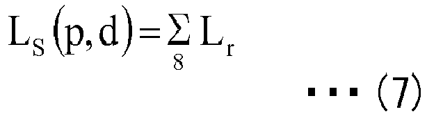
- The synthesis cost value Ls (p, d) calculated as described above can be expressed by a graph of a synthesis cost curve, in which the synthesis cost value Ls (p, d) is indicated for each shift amount d, as illustrated in
FIG. 14 . InFIG. 14 , the synthesis cost value Ls is minimum in the case of the shift amount d=3, and therefore this is calculated as a parallax value Δ=3. Note that in the above description, the number of r values is eight; however, the present embodiment is not so limited. For example, the eight directions may be further divided by two to obtain 16 directions, the eight directions may be further divided by three to obtain 24 directions, etc. Furthermore, the cost value C is indicated as the "dissimilarity"; however, the cost value C may be expressed as a "similarity" that is the inverse number of the dissimilarity. In this case, as the method of calculating the cost value C, a publicly known method such as NCC (Normalized Cross Correlation), etc., is applied. Furthermore, in this case, a parallax value Δ is derived, such that the synthesis cost value Ls is not minimum but "maximum". Note that both the dissimilarity and the similarity may be inclusively expressed as a "matching degree". - Note that part of the process by the processing device may be executed by the ECU, and part of the process by the ECU may be executed by the processing device. Furthermore, there may be a single control system including the functions of both the processing device and the ECU. In this case, the object detection program and the movable body control program may be stored in a single memory.
- Furthermore, instead of a memory, another storage medium may be used, such as a hard disk, etc.
- Furthermore, the control targets of the movable body control system are the braking device and the operating device of the vehicle; however, the present embodiment is not so limited. For example, the control target may be either one of the braking device or the operating device, and the driving source of the vehicle (for example, the engine and the motor) may be included as at least one of the control targets.
- Furthermore, the movable body control system includes a brake control unit and an operation control unit for controlling the vehicle main body; however, instead of or in addition to these units, an alert device may be included for outputting an alert sound or an alert display for prompting the attention of the driver, etc., based on detection information of an object detection device described below.
- Furthermore, a random patterned light is projected by turning on the LED array according to a light emitting pattern having an irregular light amount distribution; however, instead of the random patterned light, for example, a "design" represented by a projection mapping video, may be projected in front of the automobile. That is, the light projection device may include an image forming unit for forming an image by light, and emitting the formed light image as a random patterned light. Furthermore, the light projection device may generate and project a random patterned light by emitting light forming a mask pattern having an irregular pattern distribution.
- Furthermore, a headlight device is used as the light source unit of the light projection device; however, another exclusive-use light source unit may be provided separately from the headlight device. Furthermore, the headlight device is not limited to a device included as standard equipment in the vehicle main body; the headlight device may be a custom-made article or an optional article.
- Furthermore, as the imaging device, a
stereo camera 20 including two imaging units (two lenses) is used; however, an imaging device including three or more imaging units may be used. - The above-described light
projection control unit 51a turns on the headlight of theheadlight device 10 and projects a random patterned light, by using light pattern data (of the light to be emitted) stored in thememory 52, according to the acquired brightness information. - The "light projection device" for projecting a random patterned light is formed of the
headlight device 10 and the lightprojection control unit 51a. Furthermore, the "imaging system" for capturing the light projection range of the light projection device is formed of the light projection device and thestereo camera 20. Furthermore, the "object detection device" for detecting the object information of the light projection range of the light projection device is formed of the imaging system and the image processing system including theimage processing unit 33. - If the
ECU 50 determines that the outside of the vehicle is "dark" while the headlight is turned off, theECU 50 turns on the headlight, and if theECU 50 determines that the outside of the vehicle is "bright" while the headlight is turned on, theECU 50 turns off the headlight. - Specifically, if the
ECU 50 determines that the outside of the vehicle is "dark" while the headlight is turned off, based on a detection result from a brightness information detection unit for detecting the brightness information outside the vehicle, theECU 50 turns on the headlight by using the light pattern data, and projects a patterned light from the headlight. Note that when the driving circuit of the headlight receives the light pattern data, the driving circuit of the headlight drives the respective LEDs in the LED array according to a current value set for each LED in the light pattern data. - Specifically, the light pattern data is stored in the memory 52 (see
FIG. 5 ) of theECU 50. The CPU 51 (seeFIG. 5 ) of theECU 50 reads the light pattern data from thememory 52 when projecting light, and drives the LED array of each headlight according to the light pattern data. - Furthermore, if the
ECU 50 determines that the outside of the vehicle has become bright while the headlight is turned on, based on a detection result from the brightness information detection unit, theECU 50 turns off the headlight. - When there is an object in the light projection range, the object is irradiated by the patterned light that is projected from the headlight at the front of the vehicle. Here, the "light projection range" means the range (see
FIG. 1 ) obtained by combining the ranges in which light can be projected from the respective headlights. - The brightness information detection unit is formed of the
stereo camera 20 and theimage processing unit 33 described below for processing images captured by thestereo camera 20; however, for example, the brightness information detection unit may be formed by using a combination of a monocular camera and an image processing unit, or an illuminance sensor. That is, when the brightness information detection unit is formed of thestereo camera 20 and theimage processing unit 33, theimage processing unit 33 determines that the outside is "dark" when the total value of the luminance of all pixels in the image is less than a threshold. Furthermore, when the brightness information detection unit is an illuminance sensor, the brightness information detection unit determines that the outside is "dark" when the value acquired by the sensor is less than the threshold. As a matter of course, the method of detecting the brightness by the brightness information detection unit may have various modes, as long as the brightness outside the vehicle can be acquired. The detection result of the brightness information detection unit is sent to theECU 50. - Here, the "light pattern data" is data having an irregular light amount distribution (current value distribution), and the corresponding "patterned light" has an irregular luminance distribution (see
FIG. 4 ). Therefore, in the following, the "patterned light" is also referred to as "random patterned light". - In the random patterned light, binary or multivalued (ternary or more) luminance parts are distributed in an irregular manner (see
FIG. 4 ). - For example, when the light amount distribution of the light pattern data has binary light amount parts distributed in an irregular manner, the random patterned light has a corresponding distribution with binary luminance parts distributed in an irregular manner.
- For example, when the light amount distribution of the light pattern data has multivalued light amount parts distributed in an irregular manner, the random patterned light has a corresponding distribution with multivalued luminance parts distributed in an irregular manner.
- Here, for example, a plurality of light pattern data items having the same design but different contrasts (in the following, abbreviated as "a plurality of light pattern data items having different contrasts") may be stored in the
memory 52 of theECU 50. The plurality of light pattern data items having different contrasts may be obtained by uniformly increasing or decreasing the light amount values of all light amount parts with respect to the light pattern data used as the reference. - In this case, the
ECU 50 preferably selects an appropriate light pattern data item from among the plurality of light pattern data items having different contrasts, based on the brightness outside the vehicle, other vehicles in front of the vehicle, whether there is an object such as an obstacle, the texture amount of the environment in front of the vehicle, the parallax reliability information of the parallax image, and uses the selected light pattern data item to turn on the LED array of each headlight. - An object presence detection unit for detecting whether there is an object in front of the vehicle, may be formed of the
stereo camera 20 and theimage processing unit 33; however, for example, the object presence detection unit may be formed by using a combination of a monocular camera or a polarization camera and an image processing unit, or a laser radar. Note that when a combination of a monocular camera and an image processing unit is used as a brightness detection unit, this combination may also be used as the object presence detection unit. - As a texture detection unit for detecting the texture amount in the environment in front of the vehicle, and a unit for acquiring the parallax reliability information of the parallax image, may be formed of the
stereo camera 20 and theimage processing unit 33. - When a plurality of light pattern data items having different contrasts are stored in the
memory 52, theECU 50 can selectively project, form each headlight, one of the plurality of light pattern data items having different contrasts, according to the brightness/darkness outside the vehicle and the environment in front of the vehicle. - Incidentally, when the vehicle is in a tunnel during daytime, or in a dark place during nighttime, the headlight projects light in front of the vehicle to make the dark place bright; however, the contrast of an object that is originally in a dark place is already low, and therefore it is difficult to attain an image contrast, simply by turning on the headlight and emitting uniform light. Therefore, in a dark place, it is difficult to attain matching (correlation) between the left and right images in calculating the parallax, when acquiring a parallax image in front of the vehicle with the stereo camera. As a result, the number of ineffective parallax pixels of a subject in front of the vehicle (a person, another vehicle, an obstacle, the road surface, the background, etc.) increases, and the precision in the output parallax is low.
- The control of the vehicle main body (vehicle control process) by the movable
body control system 100 according to the present embodiment is described with reference to the flowchart ofFIG. 15 . This control is executed by theECU 50 and theprocessing device 30. That is, in the movable body control program used for controlling the movablebody control system 100, a sub program for operating theECU 50 is stored in thememory 52 of theECU 50, and a sub program for operating theprocessing device 30 is stored in thememory 29 of theprocessing device 30. - Note that the movable body control program includes all procedures of the object detection program used for controlling the object detection device. In the object detection program, a sub program for controlling the light projection device is stored in the
memory 52 of theECU 50, and a sub program for controlling thestereo camera 20 and theprocessing device 30 is stored in thememory 29 of theprocessing device 30. - Here, the control is implemented when the driver or a passenger (hereinafter, "driver, etc.") selects (ON) a safety mode (danger avoidance mode) at the operation unit of the
vehicle 1. When the safety mode is selected (ON), thestereo camera 20 captures images with both lenses in real-time, and sends the left and right images to theimage processing unit 33 in units of frames. - In the first step S1, the
ECU 50 executes a "lightprojection control process 1". The "lightprojection control process 1" is described below. - In the next step S2, a "parallax image generating process" is executed. The "parallax image generating process" is executed by the
processing device 30 in accordance with a sub program stored in thememory 29. Specifically, theprocessing device 30 generates a parallax image from images (luminance images) of the left and right frames captured by thestereo camera 20. More specifically, theimage processing unit 33 performs a pre-process of gamma correction and distortion correction, and subsequently performs parallax calculation, and sends the luminance images that have undergone the pre-process and a parallax image obtained by the parallax calculation, to the imagerecognition processing unit 34. - In the next step S3, an "image recognition process" is executed. The "image recognition process" is executed by the
processing device 30 in accordance with a sub program stored in thememory 29. Specifically, theprocessing device 30 performs image recognition (object recognition) by using a parallax image. More specifically, the imagerecognition processing unit 34 recognizes (detects) information (object information) relevant to an object in the light projection range, and sends the result (image recognition result) to theECU 50. Note that "information relevant to an object" is, for example, whether there is an object, the distance to the object, the type of object (for example, a person, a structural object, a road, etc.), etc. Note that the detection of the type of object can be performed by storing parameters such as the size, the shape, etc., of a plurality of types of objects in thememory 29 in advance, and detecting an object based on the parameters. - In the next step S4, a "brake/operation control process" is executed. The brake/operation control process" is executed by the
ECU 50 in accordance with a sub program stored in thememory 52. Specifically, theECU 50 performs automatic braking and automatic steering (control for avoiding danger), based on the received image recognition result. More specifically, thebrake control unit 51b and theoperation control unit 51c appropriately control the braking device and the operating device, respectively, based on the image recognition result. - In the next step S5, the
ECU 50 determines whether the safety mode is ON. If this determination is affirmative, the process returns to step S1, and if this determination is negative, the flow ends. - Next, the "light
projection control process 1" in step S1 of the "vehicle control process" is described with reference to the flowchart ofFIG. 16 . The lightprojection control process 1 is executed by the lightprojection control unit 51a in accordance with a sub program stored in thememory 52. Here, the brightness information is calculated in real-time by theprocessing device 30 based on the images (luminance images) in front of the vehicle captured in real-time by thestereo camera 20, and the calculated brightness information is sent to the lightprojection control unit 51a in real-time. - In the first step S11, the light
projection control unit 51a determines whether the outside of the vehicle is dark. Specifically, the lightprojection control unit 51a compares the brightness information from theprocessing device 30 with a reference value set in advance, and if the brightness information is less than the reference value, the lightprojection control unit 51a determines that the outside is "dark", and if the brightness information is greater than or equal to the reference value, the lightprojection control unit 51a determines that the outside is "not dark". If the determination in step S11 is negative (if it is determined as not dark), the process shifts to step S12, and if the determination in step S11 is affirmative (if it is determined as dark), the process shifts to step S13. - In step S12, the light
projection control unit 51a sends a light off trigger signal to theheadlight device 10. As a result, if the headlight is on, the headlight is turned off, and if the headlight is off, the off state is maintained. When step S12 is executed, the flow ends. - In step S13, the light
projection control unit 51a sends a light on trigger signal and light pattern data to theheadlight device 10. As a result, if the headlight is on, the on state is maintained, and if the headlight is off, the headlight is turned on, and a random patterned light is projected in front of the vehicle. At this time, thestereo camera 20 captures, with both lenses, the range in which the random patterned light is projected, and the captured left and right images are sent to theimage processing unit 33 in units of frames. When step S13 is executed, the flow ends. - Note that if the safety mode is ON in the vehicle control process including the light
projection control process 1, the headlight is automatically turned on when the brightness outside the vehicle is less than the reference value, and the headlight is not turned on when the brightness outside the vehicle is greater than or equal to the reference value. These automatic operations are prioritized over a manual operation of the headlight switch by the driver, etc. Meanwhile, if the safety mode is OFF, the headlight is turned on or off only by the manual operation of the headlight switch by the driver, etc. - The imaging system according to the present embodiment described above, is an imaging system installed in a vehicle main body (movable body), and includes a light projection device including the
headlight device 10 and the lightprojection control unit 51a which projects a random patterned light (a light having an irregular luminance distribution), and the stereo camera 20 (imaging device) including twoimaging units - In this case, the light projection range (range in which the random patterned light is projected) can be captured by the
stereo camera 20, and therefore it is possible to obtain an effective image for detecting object information with respect to dark places. - Furthermore, the light projection device includes, as a light source unit, the
headlight device 10 included as standard equipment in the vehicle main body for projecting a random patterned light. In this case, the random patterned light acts as illumination light for illuminating the dark places, and also as light that is effective for calculating the parallax. That is, there is no need to provide a separate light source unit in addition to theheadlight device 10. - Furthermore, the object detection device according to the present embodiment includes the imaging system and the
processing device 30 which is installed in the vehicle main body and processes images captured by thestereo camera 20 of the imaging system. - In this case, object information can be detected with high precision, based on the images (left and right images) effective for detecting the object information with respect to dark places obtained by the imaging system.
- As a result, for example, the precision in matching the left and right images in the light projection range can be increased, and the parallax of the object in the light projection range can be calculated with high precision.
- That is, a texture is applied to an object in a dark place where the contrast is initially low, and therefore a contrast appears in the image acquired by the left and right imaging units of the
stereo camera 20, the precision in matching the left and right images is secured, and the precision in calculating the parallax of an object in a dark place is increased. - As a result, with the object detection device according to the present embodiment, the precision in detecting the object information with respect to a dark place can be increased.
- Furthermore, the light projection device projects a random patterned light when the brightness outside the vehicle is less than a reference value (predetermined value) set in advance, and therefore a random patterned light can be projected only to the dark place where the precision of parallax calculation becomes low, such that needless light projection can be suppressed and energy can be saved. Note that the contrast of an object that is originally in a bright place is already high, and therefore when the outside of the vehicle is bright, the necessity of projecting a random patterned light is low.
- Furthermore, the light projection device acquires the brightness information from the luminance information of the image captured by the
stereo camera 20, and therefore compared to a case of separately providing a detection unit exclusively used for detecting the brightness information, it is possible to avoid an increase in the number of components and avoid increasing the cost. - Furthermore, the
processing device 30 further includes theimage processing unit 33 that generates a parallax image from a plurality of images captured separately by twoimaging units processing device 30 can generate a parallax image having high precision. - Furthermore, the
processing device 30 includes an imagerecognition processing unit 34 that performs image recognition with the use of the parallax image generated by theimage processing unit 33, and therefore theprocessing device 30 can obtain image recognition results having high precision. - Furthermore, the movable
body control system 100 includes the object detection device and theECU 50, which is installed in the vehicle main body and controls the vehicle main body based on an image recognition result obtained by theprocessing device 30 of the object detection device; therefore the movablebody control system 100 can prevent the traveling vehicle main body from colliding with the object. - Furthermore, the vehicle 1 (movable body device) includes the movable
body control system 100 and the vehicle main body (movable body) in which the movablebody control system 100 is installed, and therefore thevehicle 1 has superior safety. - Furthermore, the light projection device according to the present embodiment projects a random patterned light in the imaging range of the
stereo camera 20 including twoimaging units stereo camera 20 to acquire an image that makes it possible to precisely calculate the parallax of an object in the light projection range even in a dark place. - Note that, as can be understood from the above description, the light projection device, the imaging system, and the object detection device according to an embodiment of the present invention are devices that are particularly effective when used in a dark environment. These devices do not necessarily need to be installed in a movable body such as a vehicle main body, and these devices are expected to be used in various fields. Note that when the light projection device, the imaging system, and the object detection device are not installed in a movable body, a light source unit is used instead of the headlight device.
- Furthermore, the object detection method using the object detection device according to the present embodiment includes a step of projecting a random patterned light from the vehicle main body, a step of capturing the range in which the random patterned light is projected from two positions of the movable body, and a step of processing the image captured in the capturing step.
- In this case, the range in which the random patterned light is projected can be captured from two positions, and therefore it is possible to obtain images that are effective for detecting object information with respect to dark places, and the object information can be detected from the image with high precision.
- As a result, by the object detection method according to the present embodiment, the detection precision of object information with respect to dark places can be increased.
- Furthermore, the object detection method further includes a step of generating a parallax image from the plurality of images separately captured from a plurality of positions in the capturing step, and therefore a parallax image having high precision can be generated.
- Furthermore, a movable body control method using the movable body control system according to the present embodiment includes a step of projecting a random patterned light from the vehicle main body, a step of capturing the range in which the random patterned light is projected from a plurality of positions of the movable body, a step of generating a parallax image from the plurality of images separately captured from a plurality of positions in the capturing step, a step of performing image recognition by using the parallax image generated in the step of generating a parallax image, and a step of controlling the vehicle main body based on the recognition result obtained in the step of performing image recognition.
- In this case, it is possible to prevent the travelling vehicle main body from colliding with the object.
- Furthermore, the object detection program used for controlling the object detection device according to the present embodiment, causes a computer to execute the above object detection method, which includes a step of projecting a random patterned light from the vehicle main body, a step of capturing the range in which the random patterned light is projected from a plurality of positions of the movable body, and a step of processing the image captured in the capturing step.
- In this case, the range in which the random patterned light is projected can be captured from two positions, and therefore it is possible to obtain images that are effective for detecting object information with respect to dark places, and the object information can be detected from the image with high precision.
- As a result, by the object detection program according to the present embodiment, the detection precision of object information with respect to dark places can be increased.
- Furthermore, the object detection program further includes a step of generating a parallax image from the plurality of images separately captured from a plurality of positions in the capturing step, and therefore a parallax image having high precision can be generated.
- Furthermore, a movable body control program used for controlling the movable body control system according to the present embodiment includes a step of projecting a random patterned light from the vehicle main body, a step of capturing the range in which the random patterned light is projected from a plurality of positions of the movable body, a step of generating a parallax image from the plurality of images separately captured from a plurality of positions in the capturing step, a step of performing image recognition by using the parallax image generated in the step of generating a parallax image, and a step of controlling the vehicle main body based on the recognition result obtained in the step of performing image recognition.
- In this case, it is possible to prevent the travelling vehicle main body from colliding with the object.
- Furthermore, part of the object detection program is stored in the
memory 29, and the remaining part of the object detection program is stored in thememory 52, and therefore the object detection program can appropriately cause the object detection device to operate according to the object detection program. - Furthermore, part of the movable body control program is stored in the
memory 29, and the remaining part of the movable body control program is stored in thememory 52, and therefore the movable body control program can appropriately cause the movablebody control system 100 to operate according to the movable body control program. - Several modified examples of the above embodiment are described below.
- A movable body control system according to modified example 1 has the same configuration as the movable
body control system 100 according to the above embodiment. In modified example 1, the light projection control process differs from that of the above embodiment. - In modified example 1, the
memory 52 of theECU 50 stores two light pattern data items having different contrasts (high contrast light pattern data and low contrast light pattern data). When the lightprojection control unit 51a turns on the headlight, the lightprojection control unit 51a selects one of the two light pattern data items according to the brightness outside the vehicle, and turns on the LED array of each headlight by using the selected light pattern data. - In the following, a light
projection control process 2 of modified example 1 is described with reference to the flowchart ofFIG 17 . The lightprojection control process 2 is executed by the lightprojection control unit 51a in accordance with a sub program stored in thememory 52. Here, the brightness information is calculated in real-time by theprocessing device 30 based on the images (luminance images) in front of the vehicle captured in real-time by thestereo camera 20, and the calculated brightness information is sent to the lightprojection control unit 51a in real-time. - In the first step S21, the light
projection control unit 51a determines whether the received brightness information is less than a first reference value. If the determination is negative in step S21, the process shifts to step S22, and if the determination is affirmative in step S21, the process shifts to step S23. Here, if the brightness information is greater than or equal to the first reference value (in the case of shifting to step S22), the level of the brightness is generally perceived as "bright". - In step S22, the light
projection control unit 51a sends a light off trigger signal to theheadlight device 10. As a result, if the headlight is on, the headlight is turned off, and if the headlight is off, the off state is maintained. When step S22 is executed, the flow ends. - In step S23, the light
projection control unit 51a determines whether the received brightness information is less than a second reference value, which is less than the first reference value. If the determination is affirmative in step S23, the process shifts to step S24, and if the determination is negative in step S23, the process shifts to step S25. Here, if the brightness information is less than the first reference value and greater than or equal to the second reference value (in the case of shifting to step S25), the level of the brightness is generally perceived as "dim". If the brightness information is less than the second reference value (in the case of shifting to step S24), the level of the brightness is generally perceived as "dark". - In step S24, the light
projection control unit 51a sends a light on trigger signal and high contrast light pattern data to theheadlight device 10. As a result, if the headlight is on, the on state is maintained, and if the headlight is off, the headlight is turned on, and a high contrast random patterned light is projected in front of the vehicle. At this time, thestereo camera 20 captures, with both lenses, the range in which the high contrast random patterned light is projected, and the captured left and right images are sent to theimage processing unit 33 in units of frames. When step S24 is executed, the flow ends. - In step S25, the light
projection control unit 51a sends a light on trigger signal and low contrast light pattern data to theheadlight device 10. As a result, if the headlight is on, the on state is maintained, and if the headlight is off, the headlight is turned on, and a low contrast random patterned light is projected in front of the vehicle. At this time, thestereo camera 20 captures, with both lenses, the range in which the low contrast random patterned light is projected, and the captured left and right images are sent to theimage processing unit 33 in units of frames. When step S25 is executed, the flow ends. - Note that if the safety mode is ON in the vehicle control process including the light
projection control process 2, the headlight is automatically turned on when the brightness information outside the vehicle is less than the first reference value, and the headlight is not turned on when the brightness information outside the vehicle is greater than or equal to the first reference value. These automatic operations are prioritized over a manual operation of the headlight switch by the driver, etc. Meanwhile, if the safety mode is OFF, the headlight device 10is turned on or off only by the manual operation of the headlight switch by the driver, etc. - In modified example 1 described above, the light projection device including the light
projection control unit 51a and theheadlight device 10 adjusts the contrast of the random patterned light according to the brightness outside the vehicle (adjusts the luminance distribution), when projecting the random patterned light. - In this case, it is possible to project a random patterned light having a contrast that is appropriate for parallax calculation according to the brightness outside the vehicle.
- For example, when the outside is "dim", in which the attention of the driver becomes distracted, by projecting a random patterned light having a low contrast, the parallax can be calculated with high precision, and an unpleasantness in the visibility perceived by the driver, due to the random patterned light, can be reduced. As a result, an increase in the safety by the system, and the visibility, can both be attained.
- For example, when the outside is "dark", which is disadvantageous for calculating the parallax, by projecting a random patterned light having a high contrast, the parallax can be calculated with high precision. As a result, the safety by the system can be secured.
- Note that in the above modified example 1, two reference values are set, and if the brightness information is less than at least one of the two reference values, one of two kinds of random patterned light having different contrasts is selectively projected; however, three or more reference values may be set, and one of the three or more kinds of random patterned light having different contrasts may be selectively projected as the brightness information changes across the respective reference values. In this case also, as the brightness information decreases (darker), a random patterned light having a higher contrast is preferably projected.
- In modified example 2, the configuration of the movable body control system and the light projection control process differ from those of the above embodiment. A
processing device 60 in a movablebody control system 200 according to modified example 2 illustrated inFIG. 18 , includes a vehicle front texture information CPU I/F 36 and a texture information transfer-use I/F 39, in addition to theprocessing device 30 according to the above embodiment. Furthermore, anECU 70 of the movablebody control system 200 includes a CPU I/F 54, in addition to theECU 50 according to the above embodiment. - The
image processing unit 33 of theprocessing device 60 calculates vehicle front texture information from the left and right images (luminance images) captured by thestereo camera 20, and sends the calculated vehicle front texture information to theCPU 31 via the vehicle front texture information CPU I/F 36. TheCPU 31 sends the received vehicle front texture information, to theECU 50 via the texture information transfer-use I/F 39. - The
CPU 51 of theECU 70 acquires the texture information from theCPU 31, via the texture information transfer-use I/F 39 and the CPU I/F 54. - In modified example 2, the
memory 52 of theECU 70 stores two light pattern data items having different contrasts (high contrast light pattern data and low contrast light pattern data). When the lightprojection control unit 51a turns on theheadlight device 10, the lightprojection control unit 51a selects one of the two light pattern data items according to whether there is an object in front of the vehicle, and turns on the LED array of each headlight by using the selected one of the light pattern data items. - In the following, a light
projection control process 3 of modified example 2 is described with reference to the flowchart ofFIG 19 . The lightprojection control process 3 is executed by the lightprojection control unit 51a in accordance with a sub program stored in thememory 52. Here, the brightness information is calculated in real-time by theprocessing device 60 based on the images (luminance images) in front of the vehicle captured in real-time by thestereo camera 20, and the calculated brightness information is sent to the lightprojection control unit 51a in real-time. - In the first step S31, the light
projection control unit 51a determines whether the outside of the vehicle is dark. Specifically, the lightprojection control unit 51a compares the brightness information from theprocessing device 60 with a reference value set in advance, and if the brightness information is less than the reference value, the lightprojection control unit 51a determines that the outside is "dark", and if the brightness information is greater than or equal to the reference value, the lightprojection control unit 51a determines that the outside is "not dark". If the determination in step S31 is negative (if it is determined as not dark), the process shifts to step S32, and if the determination in step S31 is affirmative (if it is determined as dark), the process shifts to step S33. - In step S32, the light
projection control unit 51a sends a light off trigger signal to theheadlight device 10. As a result, if the headlight is on, the headlight is turned off, and if the headlight is off, the off state is maintained. When step S32 is executed, the flow ends. - In step S33, it is determined whether there is an object in front of the vehicle. Here, the
processing device 60 determines whether there is an object, and outputs the determination result to theECU 70. Specifically, theimage processing unit 33 determines whether there is an object by determining the texture amount in a vehicle front area in the image (luminance image) from thestereo camera 20, and outputs the determination result to the lightprojection control unit 51a. More specifically, if the texture amount is greater than or equal to a threshold, theimage processing unit 33 determines that "there is an object", and if the texture amount is less than a threshold, theimage processing unit 33 determines that "there is no object". The method of determining the texture amount is described below. If the determination in step S33 is affirmative, the process shifts to step S34, and if the determination in step S33 is negative, the process shifts to step S35. Note that the determination of whether there is an object in front of the vehicle is not limited to a determination by the texture amount, and various methods may be used. For example, a publicly known pattern matching method may be used to recognize an object in front of the vehicle. However, the determination of whether there is an object in front of the vehicle requires fast calculation, and therefore it is effective to determine whether there is an object according to the texture amount. - In step S34, the light
projection control unit 51a sends a light on trigger signal and high contrast light pattern data to theheadlight device 10. As a result, if the headlight is on, the on state is maintained, and if the headlight is off, the headlight is turned on, and a high contrast random patterned light is projected in front of the vehicle. At this time, thestereo camera 20 captures, with both lenses, the range in which the high contrast random patterned light is projected, and the captured left and right images are sent to theimage processing unit 33 in units of frames. When step S34 is executed, the flow ends. - In step S35, the light
projection control unit 51a sends a light on trigger signal and low contrast light pattern data to theheadlight device 10. As a result, if the headlight is on, the on state is maintained, and if the headlight is off, the headlight is turned on, and a low contrast random patterned light is projected in front of the vehicle. At this time, thestereo camera 20 captures, with both lenses, the range in which the low contrast random patterned light is projected, and the captured left and right images are sent to theimage processing unit 33 in units of frames. When step S35 is executed, the flow ends. - In modified example 2 described above, the light projection device including the light
projection control unit 51a and theheadlight device 10 adjusts the contrast (adjusts the luminance distribution) of the random patterned light according to whether there is an object in front of the vehicle (in the light projection range of the light projection device), when the light projection device projects the random patterned light. - In this case, it is possible to project a random patterned light having a contrast that is sufficient according to whether there is an object in front of the vehicle, that is, according to the risk of collision.
- For example, when "there is no object" and therefore the risk of collision is low, by projecting a random patterned light having a low contrast, the parallax can be calculated with high precision, and an unpleasantness in the visibility perceived by the driver, due to the random patterned light, can be reduced. As a result, the safety by the system, and the visibility, can both be attained.
- For example, when "there is an object" and therefore the risk of collision is high, by projecting a random patterned light having a high contrast, the parallax can be calculated with even higher precision. As a result, the safety by the system can be secured.
- Furthermore, the
processing device 60 detects whether there is an object from an image captured by thestereo camera 20, and therefore compared to a case of separately providing a detection unit exclusively used for detecting whether there is an object, it is possible to avoid an increase in the number of components and avoid increasing the cost. - In modified example 3, the configuration of the movable body control system is the same as that of the movable
body control system 200 according to modified example 2. In modified example 3, the light projection control process differs from that of the above embodiment. - In modified example 3, the
memory 52 of theECU 70 stores two light pattern data items having different contrasts (high contrast light pattern data and low contrast light pattern data). When the lightprojection control unit 51a turns on theheadlight device 10, the lightprojection control unit 51a selects one of the two light pattern data items according to the sum of the texture amount in front of the vehicle and the texture amount diagonally in front of the vehicle, and turns on the LED array of each headlight by using the selected one of the light pattern data items. - In the following, a light projection control process 4 of modified example 3 is described with reference to the flowchart of
FIG 20 . The light projection control process 4 is executed by the lightprojection control unit 51a in accordance with a sub program stored in thememory 29. Here, the brightness information is calculated in real-time by theprocessing device 60 based on the images (luminance images) in front of the vehicle captured in real-time by thestereo camera 20, and the calculated brightness information is sent to the lightprojection control unit 51a in real-time. - In the first step S41, the light
projection control unit 51a determines whether the outside of the vehicle is dark. Specifically, the lightprojection control unit 51a compares the brightness information from theprocessing device 60 with a reference value set in advance, and if the brightness information is less than the reference value, the lightprojection control unit 51a determines that the outside is "dark", and if the brightness information is greater than or equal to the reference value, the lightprojection control unit 51a determines that the outside is "not dark". If the determination in step S41 is negative (if it is determined as not dark), the process shifts to step S42, and if the determination in step S41 is affirmative (if it is determined as dark), the process shifts to step S43. - In step S42, the light
projection control unit 51a sends a light off trigger signal to theheadlight device 10. As a result, if the headlight is on, the headlight is turned off, and if the headlight is off, the off state is maintained. When step S42 is executed, the flow ends. - In step S43, it is determined whether the texture amount of the entire image captured by the
stereo camera 20 is large. Here, theprocessing device 60 determines the texture amount, and outputs the determination result to theECU 70. Specifically, theimage processing unit 33 determines whether the sum (hereinafter, also referred to as the "texture total amount") of the texture amount in an area in front of the vehicle and the texture amount in an area diagonally in front of the vehicle in the image (luminance image) from thestereo camera 20, is greater than or equal to a threshold, and outputs the determination result to the lightprojection control unit 51a. More specifically, if the texture total amount is greater than or equal to a threshold, theimage processing unit 33 determines that "the texture total amount is large", and if the texture total amount is less than a threshold, theimage processing unit 33 determines that "the texture total amount is not large". The method of determining the texture total amount is described below. If the determination in step S43 is affirmative, the process shifts to step S44, and if the determination in step S43 is negative, the process shifts to step S45. - In step S44, the light
projection control unit 51a sends a light on trigger signal and low contrast light pattern data to theheadlight device 10. As a result, if the headlight is on, the on state is maintained, and if the headlight is off, the headlight is turned on, and a low contrast random patterned light is projected in front of the vehicle. At this time, thestereo camera 20 captures, with both lenses, the range in which the low contrast random patterned light is projected, and the captured left and right images are sent to theimage processing unit 33 in units of frames. When step S44 is executed, the flow ends. - In step S45, the light
projection control unit 51a sends a light on trigger signal and high contrast light pattern data to theheadlight device 10. As a result, if the headlight is on, the on state is maintained, and if the headlight is off, the headlight is turned on, and a high contrast random patterned light is projected in front of the vehicle. At this time, thestereo camera 20 captures, with both lenses, the range in which the high contrast random patterned light is projected, and the captured left and right images are sent to theimage processing unit 33 in units of frames. When step S45 is executed, the flow ends. - In modified example 3 described above, the light projection device including the light
projection control unit 51a and theheadlight device 10 adjusts the contrast (adjusts the luminance distribution) of the random patterned light based on the sum of the texture amount in front of the vehicle and the texture amount diagonally in front of the vehicle (the texture total amount in the light projection range of the headlight device 10), when the light projection device projects the random patterned light. - In this case, it is possible to project a random patterned light having a contrast that is sufficient according to the sum of the texture amount in front of the vehicle and the texture amount diagonally in front of the vehicle (the texture total amount).
- For example, when the texture total amount is large (when travelling in a busy street, in forest land, etc.), by projecting a random patterned light having a low contrast, the parallax can be calculated with high precision, and an unpleasantness in the visibility perceived by the driver, due to the random patterned light, can be reduced. As a result, the safety by the system, and the visibility, can both be attained.
- For example, when the texture total amount is small (when travelling along the seaside, in the countryside, in the wilderness, etc.), by projecting a random patterned light having a high contrast, the parallax can be calculated with even higher precision. As a result, the safety by the system can be secured.
- Furthermore, the
processing device 60 acquires the texture amount in the light projection range from an image captured by thestereo camera 20, and therefore compared to a case of separately providing a detection unit exclusively used for detecting the texture amount, it is possible to avoid an increase in the number of components and avoid increasing the cost. - Note that in the above modified example 3, one threshold of the texture total amount is set, and one of two kinds of random patterned light having different contrasts is selectively projected as the texture amount changes across the threshold; however, two or more thresholds of the texture total amount may be set, and one of three or more kinds of random patterned light having different contrasts may be selectively projected as the texture amount changes across the respective thresholds. In this case also, as the texture total amount decreases, a random patterned light having a higher contrast is preferably projected.
- Here, the method of determining the texture amount in modified example 2 and the method of determining the texture total amount in modified example 3 are described with reference to
FIGS. 21A and 21B . - First, in
FIG. 21A , the texture definition equation of a certain pixel is set as Txt=|(A+B)-(C+D)|. ∥ means an absolute value.
A is a pixel value of a pixel that is two pixels away from the certain pixel on the left side of the certain pixel.
B is a pixel value of a pixel that is one pixel away from the certain pixel on the left side of the certain pixel.
C is a pixel value of a pixel that is one pixel away from the certain pixel on the right side of the certain pixel.
D is a pixel value of a pixel that is two pixels away from the certain pixel on the right side of the certain pixel.
Th is the texture threshold.
If Txt>Th is satisfied, the corresponding pixel is determined to have texture, and a texture flag flag=1 is set.
If Txt>Th is not satisfied, the corresponding pixel is determined not to have texture, and a texture flag flag=0 is set.
This process is performed for each of the pixels in the entire image, or in a determination target area that is a target of determining the texture amount in the image. By counting the number of pixels having flag=1, it is possible to determine the texture amount of the entire image or the entire determination target area (seeFIG. 21B ). For example, if the texture amount only in the area in front of the vehicle is to be determined, the range of the area in front of the vehicle is specified in advance (for example, four coordinate points), and the number of pixels having flag=1 in the range is counted. For example, when the texture amount in the areas diagonally in front of the vehicle is to be determined, the areas on both sides of the image are specified as the target areas (coordinate points are specified), and the number of pixels having flag=1 in the range is counted. Note that the above definition equation of the "texture amount" is one example; for example, various equations may be used, such as Txt=|A-C| and Txt=|B-D|. - In modified example 4, the configuration of the movable body control system is the same as that of the movable
body control system 100 according to the above embodiment. In modified example 4, the light projection control process differs from that of the above embodiment. - In modified example 4, the
memory 52 of theECU 50 stores two light pattern data items having different contrasts (high contrast light pattern data and low contrast light pattern data). When the lightprojection control unit 51a turns on theheadlight device 10, the lightprojection control unit 51a selects one of the two light pattern data items according to the number of invalid parallax pixels in the parallax image (reliability information in parallax), and turns on the LED array of each headlight by using the selected one of the light pattern data items. - In the following, a light
projection control process 5 of modified example 4 is described with reference to the flowchart ofFIG 22 . The lightprojection control process 5 is executed by the lightprojection control unit 51a in accordance with a sub program stored in thememory 52. Here, the brightness information is calculated in real-time by theprocessing device 30 based on the images (luminance images) in front of the vehicle captured in real-time by thestereo camera 20, and the calculated brightness information is sent to the lightprojection control unit 51a in real-time. - In the first step S51, the light
projection control unit 51a determines whether the outside of the vehicle is dark. Specifically, the lightprojection control unit 51a compares the brightness information from theprocessing device 30 with a reference value set in advance, and if the brightness information is less than the reference value, the lightprojection control unit 51a determines that the outside is "dark", and if the brightness information is greater than or equal to the reference value, the lightprojection control unit 51a determines that the outside is "not dark". If the determination in step S51 is negative (if it is determined as not dark), the process shifts to step S52, and if the determination in step S51 is affirmative (if it is determined as dark), the process shifts to step S53. - In step S52, the light
projection control unit 51a sends a light off trigger signal to theheadlight device 10. As a result, if the headlight is on, the headlight is turned off, and if the headlight is off, the off state is maintained. When step S52 is executed, the flow ends. - In step S53, the light
projection control unit 51a sends a light on trigger signal and low contrast light pattern data to theheadlight device 10. As a result, if the headlight is on, the on state is maintained, and if the headlight is off, the headlight is turned on, and a low contrast random patterned light is projected in front of the vehicle. At this time, thestereo camera 20 captures, with both lenses, the range in which the low contrast random patterned light is projected, and the captured left and right images are sent to theimage processing unit 33 in units of frames. When step S53 is executed, the process shifts to step S54. - In step S54, it is determined whether many invalid parallax pixels are present in the parallax image. Here, the
processing device 30 determines whether the number of invalid parallax pixels in the parallax image is large or small, and outputs the determination result to theECU 50. Specifically, theimage processing unit 33 performs a pre-process of gamma correction, distortion correction, etc., on the image (luminance image) captured by thestereo camera 20, subsequently performs parallax calculation, and sends a parallax image obtained by the parallax calculation to the imagerecognition processing unit 34. The imagerecognition processing unit 34 determines whether the number of invalid parallax pixels in the received parallax image is greater than or equal to a threshold, and outputs the determination result to the lightprojection control unit 51a. If the determination in step S54 is affirmative, the process shifts to step S55, and if the determination in step S54 is negative, the flow ends. - In step S55, the light
projection control unit 51a sends a light on trigger signal and high contrast light pattern data to theheadlight device 10. As a result, if the headlight is on, the on state is maintained, and if the headlight is off, the headlight is turned on, and a high contrast random patterned light is projected in front of the vehicle. At this time, thestereo camera 20 captures, with both lenses, the range in which the high contrast random patterned light is projected, and the captured left and right images are sent to theimage processing unit 33 in units of frames. When step S55 is executed, the flow ends. - In modified example 4 described above, the light projection device including the light
projection control unit 51a and theheadlight device 10 adjusts the contrast of the random patterned light (adjusts the luminance distribution), based on the number of invalid parallax pixels in the parallax image, that is, the reliability information of parallax, when projecting the random patterned light. - In this case, it is possible to project a random patterned light having a contrast that is appropriate for parallax calculation according to the reliability information of parallax.
- For example, when the number of invalid parallax pixels is small (when the reliability information of parallax is high), by projecting a random patterned light having a low contrast, the parallax can be calculated with high precision, and an unpleasantness in the visibility perceived by the driver, due to the random patterned light, can be reduced. As a result, the safety by the system, and the visibility, can both be attained.
- For example, when the number of invalid parallax pixels is large (when the reliability information of parallax is low), by projecting a random patterned light having a high contrast, the parallax can be calculated with high precision. As a result, the safety by the system can be secured.
- Furthermore, the
processing device 30 acquires the number of invalid parallax pixels (reliability information of parallax) form an image captured by thestereo camera 20, and therefore compared to a case of acquiring the number of invalid parallax pixels by another means, the configuration can be simplified, and an increase in cost can be avoided. - Note that in the above modified example 4, one threshold of the number of invalid parallax pixels is set, and one of two kinds of random patterned light having different contrasts is selectively projected as the number of invalid parallax pixels changes across the threshold; however, two or more thresholds of the number of invalid parallax pixels may be set, and one of three or more kinds of random patterned light having different contrasts may be selectively projected as the number of invalid parallax pixels changes across the respective thresholds.. In this case also, as the number of invalid parallax pixels increases, a random patterned light having a higher contrast is preferably projected.
- In modified example 5, the configuration of the movable body control system is the same as that of the movable
body control system 100 according to the above embodiment. In modified example 5, the light projection control process differs from that of the above embodiment. - In modified example 5, the
memory 52 of theECU 50 stores two light pattern data items having different contrasts (high contrast light pattern data and low contrast light pattern data). When the lightprojection control unit 51a turns on theheadlight device 10, the lightprojection control unit 51a selects one of the two light pattern data items according to whether there is an object in front of the vehicle, and turns on the LED array of each headlight by using the selected one of the light pattern data items. - In the following, a light projection control process 6 of modified example 5 is described with reference to the flowchart of
FIG 23 . The light projection control process 6 is executed by the lightprojection control unit 51a in accordance with a sub program stored in thememory 52. Here, the brightness information is calculated in real-time by theprocessing device 30 based on the images (luminance images) in front of the vehicle captured in real-time by thestereo camera 20, and the calculated brightness information is sent to the lightprojection control unit 51a in real-time. - In the first step S61, the light
projection control unit 51a determines whether the outside of the vehicle is dark. Specifically, the lightprojection control unit 51a compares the brightness information from theprocessing device 30 with a reference value set in advance, and if the brightness information is less than the reference value, the lightprojection control unit 51a determines that the outside is "dark", and if the brightness information is greater than or equal to the reference value, the lightprojection control unit 51a determines that the outside is "not dark". If the determination in step S61 is negative (if it is determined as not dark), the process shifts to step S62, and if the determination in step S61 is affirmative (if it is determined as dark), the process shifts to step S63. - In step S62, the light
projection control unit 51a sends a light off trigger signal to theheadlight device 10. As a result, if the headlight is on, the headlight is turned off, and if the headlight is off, the off state is maintained. When step S62 is executed, the flow ends. - In step S63, the light
projection control unit 51a sends a light on trigger signal and low contrast light pattern data to theheadlight device 10. As a result, if the headlight is on, the on state is maintained, and if the headlight is off, the headlight is turned on, and a low contrast random patterned light is projected in front of the vehicle. At this time, thestereo camera 20 captures, with both lenses, the range in which the low contrast random patterned light is projected, and the captured left and right images are sent to theimage processing unit 33 in units of frames. When step S63 is executed, the process shifts to step S64. - In step S64, it is determined whether there is an object in front of the vehicle. Specifically, the
processing device 30 generates a parallax image, determines whether there is an object by performing image recognition by using the parallax image, and outputs the determination result to theECU 50. More specifically, theimage processing unit 33 performs a pre-process of gamma correction, distortion correction, etc., on the images (luminance images) captured by thestereo camera 20, subsequently performs parallax calculation, and sends the luminance images that have undergone the pre-process and a parallax image obtained by the parallax calculation to the imagerecognition processing unit 34. The imagerecognition processing unit 34 determines whether there is an object by performing image recognition by using the luminance images and the parallax image, and outputs the determination result to the lightprojection control unit 51a. If the determination in step S64 is affirmative, the process shifts to step S65, and if the determination in step S64 is negative, the flow ends. - In step S65, the light
projection control unit 51a sends a light on trigger signal and high contrast light pattern data to theheadlight device 10. As a result, if the headlight is on, the on state is maintained, and if the headlight is off, the headlight is turned on, and a high contrast random patterned light is projected in front of the vehicle. At this time, thestereo camera 20 captures, with both lenses, the range in which the high contrast random patterned light is projected, and the captured left and right images are sent to theimage processing unit 33 in units of frames. When step S65 is executed, the flow ends. - In modified example 5 described above, a low contrast random patterned light is projected when the outside of the vehicle is dark, a parallax image is generated form a captured image, and image recognition is performed by using the parallax image, and therefore it can be detected whether there is an object in front of the vehicle with high precision. Then, the light projection device adjusts the contrast of the random patterned light (adjusts the luminance distribution), based on whether there is an object in front of the vehicle. That is, when it is detected that "there is no object" in front of the vehicle, projection of a low contrast random patterned light is continued, and when it is detected that "there is an object" in front of the vehicle, the projected light is switched to a high contrast random patterned light.
- In this case, it is possible to project a random patterned light having an appropriate contrast according to whether there is an object in front of the vehicle.
- As a result, it is possible to project a random patterned light having an appropriate contrast according to whether there is an object in front of the vehicle, that is, according to the risk of collision.
- For example, when "there is no object" and therefore the risk of collision is low, by projecting a random patterned light having a low contrast, the parallax can be calculated with high precision, and an unpleasantness in the visibility perceived by the driver, due to the random patterned light, can be reduced. As a result, the safety by the system, and the visibility, can both be attained.
- For example, when "there is an object" and therefore the risk of collision is high, by projecting a random patterned light having a high contrast, the parallax can be calculated with high precision. As a result, the safety by the system can be secured.
- Furthermore, the
processing device 30 detects whether there is an object from an image captured by thestereo camera 20, and therefore compared to a case of separately providing a detection unit exclusively used for detecting whether there is an object, it is possible to avoid an increase in the number of components and avoid increasing the cost. - Note that control may be implemented by practically replacing step S63 and step S65 with each other in the flowchart of
FIG. 23 , as in a light projection control process 7 in modified example 6 illustrated inFIG. 24 (steps S71 through S75). Modified example 6 can also obtain the same effects as those of modified example 5. - In the following, examples 1 through 5 (parallax calculation method used: SGM algorithm) according to embodiments and modified examples of the present invention are described (see table 1).
- While the vehicle was traveling, the driver determined that it is dark, and manually turned on the headlight. An uneven contrast was applied to the light emitted from the headlight. As a result, the number of invalid parallax pixels in front of the vehicle was reduced.
- A brightness information detection unit was used. While the vehicle was traveling, it was automatically determined that it is dark, and the headlight was automatically turned on. An uneven contrast was applied to the light emitted from the headlight. As a result, the number of invalid parallax pixels in front of the vehicle was reduced.
- A brightness information detection unit and an object presence detection unit were used. While the vehicle was traveling, it was automatically determined that it is dark, and the headlight was automatically turned on. Furthermore, while the vehicle was traveling, another vehicle was detected at 40 m ahead in front of the vehicle, and therefore an uneven contrast was applied to the light emitted from the headlight. As a result, the number of invalid parallax pixels in front of the vehicle was reduced. Particularly, the number of invalid parallax pixels of the other vehicle in front of the vehicle was reduced.
- A brightness information detection unit and a texture detection unit were used. While the vehicle was traveling, it was automatically determined that it is dark, and the headlight was automatically turned on. Furthermore, while the vehicle was traveling, it was determined that there was not much texture remaining in the luminance image, and therefore an uneven contrast was applied to the light emitted from the headlight. As a result, the number of invalid parallax pixels in front of the vehicle was reduced.
- A brightness detection unit and a parallax image reliability information (number of invalid parallax pixels) acquiring unit were used. While the vehicle was traveling, it was automatically determined that it is dark, and the headlight was automatically turned on. Furthermore, while the vehicle was traveling, it was determined that the number of invalid parallax pixels in the parallax image was 65% with respect to the total number of pixels, and therefore an uneven contrast was applied to the light emitted from the headlight. As a result, the number of invalid parallax pixels in front of the vehicle was reduced.
[Table 1] RESULTS OF EXAMPLES 1 THROUGH 5 BRIGHTNESS DETECTION DETECTION OF OBJECT IN FRONT OF VEHICLE DETECTION OF TEXTURE IN FRONT OF VEHICLE DETECTION OF NUMBER OF INVALID PARALLAX PIXELS IN FRONT OF VEHICLE RATIO OF NUMBER OF INVALID PARALLAX PIXELS WITH RESPECT TO NUMBER OF ALL PIXELS OUTPUT RESULT OF PARALLAX IMAGE SGM PARALLAX CALCULATION RESULT WHEN PRESENT INVENTION IS IMPLEMENTED SGM PARALLAX CALCULATION RESULT WHEN PRESENT INVENTION IS NOT IMPLEMENTED EXAMPLE 1 OFF (MANUAL OPERATION BY DRIVER) OFF OFF OFF 40% 65% NUMBER OF INVALID PARALLAX PIXELS IN FRONT OF VEHICLE DECREASED. EXAMPLE 2 ON OFF OFF OFF 40% 65% NUMBER OF INVALID PARALLAX PIXELS IN FRONT OF VEHICLE DECREASED. EXAMPLE 3 ON ON OFF OFF 30% 65% NUMBER OF INVALID PARALLAX PIXELS OF OBJECT IN FRONT OF VEHICLE DECREASED. EXAMPLE 4 ON OFF ON OFF 30% 65% NUMBER OF INVALID PARALLAX PIXELS IN FRONT OF VEHICLE DECREASED. EXAMPLE 5 ON OFF OFF ON 30% 65% NUMBER OF INVALID PARALLAX PIXELS IN FRONT OF VEHICLE DECREASED. - Note that in examples 1 through 5, a stereo camera was used as the means of the detection system; however, the detection system is not so limited. As a means other than the means for acquiring the parallax information, a monocular camera, a polarization camera, a laser radar, etc., may be used.
- The present invention is not limited to the above embodiment, modified examples, or examples; and the present invention may be appropriately modified. For example, a plurality of random patterned light beams may be a plurality of random patterned light beams having different contrasts and different designs, or may be a plurality of random patterned light beams having different designs and the same contrast. The plurality of random patterned light beams may be switched manually by the driver.
- Furthermore, in the above modified examples and examples, instead of projecting a random patterned light of low contrast, a light having a design without contrast (having an even luminance distribution), or patterned light having a regular luminance distribution such as a light having regularity in the contrast, may be projected.
- According to one embodiment of the present invention, an imaging system, an image processing system, and an object detection method are provided, which are capable of obtaining an image that is effective for detecting object information with respect to a dark place.
- The imaging system, the image processing system, and the object detection method are not limited to the specific embodiments described herein, and variations and modifications may be made without departing from the spirit and scope of the present invention.
Claims (15)
- An imaging system installed in a movable body, the imaging system comprising:a light projection device configured to project a patterned light having an irregular luminance distribution; andan imaging device including a plurality of imaging units, configured to capture an image of an area within a light projection range of the light projection device.
- The imaging system according to claim 1, wherein
the light projection device includes a headlight installed in the movable body, as a light source unit. - An image processing system comprising:the imaging system according to claim 1 or 2; anda processing device configured to process the image captured by the imaging device of the imaging system, wherein the processing device is installed in the movable body.
- The image processing system according to claim 3, wherein
the light projection device projects the patterned light when brightness outside the movable body is less than a predetermined value. - The image processing system according to claim 4, wherein
the processing device calculates brightness information indicating the brightness outside the movable body, based on a luminance of the image captured by the imaging device. - The image processing system according to claim 4 or 5, wherein
the light projection device adjusts the luminance distribution of the patterned light according to the brightness information, when projecting the patterned light. - The image processing system according to claim 4 or 5, wherein
the light projection device adjusts the luminance distribution of the patterned light according to whether there is an object in the light projection range, when projecting the patterned light. - The image processing system according to claim 4 or 5, wherein
the light projection device adjusts the luminance distribution of the patterned light based on a texture amount in the light projection range, when projecting the patterned light. - The image processing system according to claim 8, wherein
the processing device calculates the texture amount, based on the image captured by the imaging device. - The image processing system according to claim 4 or 5, wherein
the processing device generates a parallax image from a plurality of the images separately captured by the plurality of imaging units when the patterned light is projected from the light projection device, and determines reliability information of the parallax image, and
the light projection device adjusts the luminance distribution of the patterned light based on the reliability information. - The image processing system according to any one of claims 6 through 10, wherein
the adjustment of the luminance distribution of the patterned light includes adjusting a design of the patterned light. - The image processing system according to any one of claims 6 through 10, wherein
the adjustment of the luminance distribution of the patterned light includes adjusting a contrast of the patterned light. - The image processing system according to any one of claims 4 through 12, wherein
the processing device generates the parallax image from the plurality of the images separately captured by the plurality of imaging units when the patterned light is projected from the light projection device. - The image processing system according to claim 13, wherein the processing device performs image recognition by using the parallax image.
- An object detection method comprising:projecting a patterned light having an irregular luminance distribution from a movable body;capturing, from a plurality of positions of the movable body, an image of an area within a range in which the patterned light is projected; andprocessing the captured image.
Applications Claiming Priority (2)
| Application Number | Priority Date | Filing Date | Title |
|---|---|---|---|
| JP2015047923 | 2015-03-11 | ||
| JP2016009428A JP6704607B2 (en) | 2015-03-11 | 2016-01-21 | Imaging system, image processing system, moving body control system, moving body device, light projecting device, object detection method, object detection program |
Publications (2)
| Publication Number | Publication Date |
|---|---|
| EP3067826A1 true EP3067826A1 (en) | 2016-09-14 |
| EP3067826B1 EP3067826B1 (en) | 2021-05-05 |
Family
ID=55699332
Family Applications (1)
| Application Number | Title | Priority Date | Filing Date |
|---|---|---|---|
| EP16158634.2A Active EP3067826B1 (en) | 2015-03-11 | 2016-03-04 | Image processing system and parallax image generation method |
Country Status (1)
| Country | Link |
|---|---|
| EP (1) | EP3067826B1 (en) |
Cited By (5)
| Publication number | Priority date | Publication date | Assignee | Title |
|---|---|---|---|---|
| CN111465819A (en) * | 2017-12-14 | 2020-07-28 | 康蒂-特米克微电子有限公司 | 3D Environment Sensing with Pseudo-Random Pattern Sequence Projection and Stereo Camera Module |
| CN112532916A (en) * | 2019-09-03 | 2021-03-19 | 皮尔茨公司 | Apparatus and method for performing security function |
| US20210232842A1 (en) * | 2018-05-24 | 2021-07-29 | Sony Corporation | Information processing apparatus, information processing method, photographing apparatus, lighting apparatus, and mobile body |
| CN113834428A (en) * | 2021-07-29 | 2021-12-24 | 阿里巴巴达摩院(杭州)科技有限公司 | Metal body thickness identification method and system, storage medium and electronic equipment |
| US20240027049A1 (en) * | 2022-07-25 | 2024-01-25 | Lumileds Llc | Controllable headlamp system |
Citations (4)
| Publication number | Priority date | Publication date | Assignee | Title |
|---|---|---|---|---|
| US20080029701A1 (en) * | 2006-07-25 | 2008-02-07 | Matsushita Electric Industrial Co. Ltd. | Night-vision imaging apparatus, control method of the same, and headlight module |
| US20080294315A1 (en) * | 1995-06-07 | 2008-11-27 | Intelligent Technologies International, Inc. | System and Method for Controlling Vehicle Headlights |
| US20110074932A1 (en) * | 2009-08-27 | 2011-03-31 | California Institute Of Technology | Accurate 3D Object Reconstruction Using a Handheld Device with a Projected Light Pattern |
| JP5138517B2 (en) | 2008-09-08 | 2013-02-06 | 株式会社小糸製作所 | Vehicle headlamp, control method for vehicle headlamp |
Family Cites Families (2)
| Publication number | Priority date | Publication date | Assignee | Title |
|---|---|---|---|---|
| JP4402400B2 (en) * | 2003-08-28 | 2010-01-20 | オリンパス株式会社 | Object recognition device |
| JP5438410B2 (en) * | 2009-07-15 | 2014-03-12 | 株式会社小糸製作所 | Vehicle headlamp device |
-
2016
- 2016-03-04 EP EP16158634.2A patent/EP3067826B1/en active Active
Patent Citations (4)
| Publication number | Priority date | Publication date | Assignee | Title |
|---|---|---|---|---|
| US20080294315A1 (en) * | 1995-06-07 | 2008-11-27 | Intelligent Technologies International, Inc. | System and Method for Controlling Vehicle Headlights |
| US20080029701A1 (en) * | 2006-07-25 | 2008-02-07 | Matsushita Electric Industrial Co. Ltd. | Night-vision imaging apparatus, control method of the same, and headlight module |
| JP5138517B2 (en) | 2008-09-08 | 2013-02-06 | 株式会社小糸製作所 | Vehicle headlamp, control method for vehicle headlamp |
| US20110074932A1 (en) * | 2009-08-27 | 2011-03-31 | California Institute Of Technology | Accurate 3D Object Reconstruction Using a Handheld Device with a Projected Light Pattern |
Cited By (15)
| Publication number | Priority date | Publication date | Assignee | Title |
|---|---|---|---|---|
| CN111465819B (en) * | 2017-12-14 | 2023-07-25 | 康蒂-特米克微电子有限公司 | 3D Environment Sensing via Projection of Pseudo-Random Pattern Sequences and Stereo Camera Module |
| CN111465819A (en) * | 2017-12-14 | 2020-07-28 | 康蒂-特米克微电子有限公司 | 3D Environment Sensing with Pseudo-Random Pattern Sequence Projection and Stereo Camera Module |
| US20240075866A1 (en) * | 2018-05-24 | 2024-03-07 | Sony Group Corporation | Information processing apparatus, information processing method, photographing apparatus, lighting apparatus, and mobile body |
| US20210232842A1 (en) * | 2018-05-24 | 2021-07-29 | Sony Corporation | Information processing apparatus, information processing method, photographing apparatus, lighting apparatus, and mobile body |
| US12485814B2 (en) * | 2018-05-24 | 2025-12-02 | Sony Group Corporation | Information processing apparatus, information processing method, photographing apparatus, lighting apparatus, and mobile body |
| US11850990B2 (en) * | 2018-05-24 | 2023-12-26 | Sony Corporation | Information processing apparatus, information processing method, photographing apparatus, lighting apparatus, and mobile body |
| CN112532916A (en) * | 2019-09-03 | 2021-03-19 | 皮尔茨公司 | Apparatus and method for performing security function |
| CN113834428B (en) * | 2021-07-29 | 2024-05-14 | 阿里巴巴达摩院(杭州)科技有限公司 | Metal body thickness identification method, system, storage medium and electronic equipment |
| CN113834428A (en) * | 2021-07-29 | 2021-12-24 | 阿里巴巴达摩院(杭州)科技有限公司 | Metal body thickness identification method and system, storage medium and electronic equipment |
| US20240029282A1 (en) * | 2022-07-25 | 2024-01-25 | Lumileds Llc | Automotive system with controllable headlamp |
| US20240027049A1 (en) * | 2022-07-25 | 2024-01-25 | Lumileds Llc | Controllable headlamp system |
| US12159464B2 (en) * | 2022-07-25 | 2024-12-03 | Lumileds, LLC | Controllable headlamp system |
| US12223735B2 (en) | 2022-07-25 | 2025-02-11 | Lumileds, LLC | Vehicle camera vision and control system and method |
| US12536804B2 (en) | 2022-07-25 | 2026-01-27 | Lumileds Singapore Pte. Ltd. | Vehicle camera vision system and method |
| US12561984B2 (en) | 2022-07-25 | 2026-02-24 | Lumileds Singapore Pte. Ltd. | Controllable headlamp |
Also Published As
| Publication number | Publication date |
|---|---|
| EP3067826B1 (en) | 2021-05-05 |
Similar Documents
| Publication | Publication Date | Title |
|---|---|---|
| EP3070641B1 (en) | Vehicle body with imaging system and object detection method | |
| JP6704607B2 (en) | Imaging system, image processing system, moving body control system, moving body device, light projecting device, object detection method, object detection program | |
| US9424462B2 (en) | Object detection device and object detection method | |
| US10755116B2 (en) | Image processing apparatus, imaging apparatus, and device control system | |
| EP2061687B1 (en) | Sight-line end estimation device and driving assist device | |
| JP6540009B2 (en) | Image processing apparatus, image processing method, program, image processing system | |
| US9224055B2 (en) | Exterior environment recognition device | |
| JP5472538B2 (en) | Distance measuring device and environmental map generating device | |
| US9311711B2 (en) | Image processing apparatus and image processing method | |
| EP2537709B1 (en) | Image processing apparatus and light distribution control method | |
| US20160019429A1 (en) | Image processing apparatus, solid object detection method, solid object detection program, and moving object control system | |
| EP3067826B1 (en) | Image processing system and parallax image generation method | |
| US20110234761A1 (en) | Three-dimensional object emergence detection device | |
| JP6782433B2 (en) | Image recognition device | |
| WO2015125297A1 (en) | Local location computation device and local location computation method | |
| JP4032843B2 (en) | Monitoring system and monitoring method, distance correction device and distance correction method in the monitoring system | |
| JP6687886B2 (en) | Image processing system, moving body control system, moving body device, object detecting method, object detecting program | |
| JP7096701B2 (en) | Imaging device | |
| CN117121062A (en) | Methods and systems for estimating depth information | |
| JP2015179066A (en) | Parallax value derivation device, apparatus control system, moving body, robot, parallax value derivation method and program | |
| JP6543935B2 (en) | PARALLEL VALUE DERIVING DEVICE, DEVICE CONTROL SYSTEM, MOBILE OBJECT, ROBOT, PARALLEL VALUE DERIVING METHOD, AND PROGRAM | |
| US20110267430A1 (en) | Detection Device of Planar Area and Stereo Camera System | |
| JP6533244B2 (en) | Object detection device, object detection method, and object detection program | |
| CN112485807A (en) | Object recognition device | |
| JP6519138B2 (en) | PARALLEL VALUE DERIVING DEVICE, MOBILE OBJECT, ROBOT, PARALLEL VALUE PRODUCTION METHOD, AND PROGRAM |
Legal Events
| Date | Code | Title | Description |
|---|---|---|---|
| PUAI | Public reference made under article 153(3) epc to a published international application that has entered the european phase |
Free format text: ORIGINAL CODE: 0009012 |
|
| 17P | Request for examination filed |
Effective date: 20160304 |
|
| AK | Designated contracting states |
Kind code of ref document: A1 Designated state(s): AL AT BE BG CH CY CZ DE DK EE ES FI FR GB GR HR HU IE IS IT LI LT LU LV MC MK MT NL NO PL PT RO RS SE SI SK SM TR |
|
| AX | Request for extension of the european patent |
Extension state: BA ME |
|
| STAA | Information on the status of an ep patent application or granted ep patent |
Free format text: STATUS: EXAMINATION IS IN PROGRESS |
|
| 17Q | First examination report despatched |
Effective date: 20170626 |
|
| GRAP | Despatch of communication of intention to grant a patent |
Free format text: ORIGINAL CODE: EPIDOSNIGR1 |
|
| STAA | Information on the status of an ep patent application or granted ep patent |
Free format text: STATUS: GRANT OF PATENT IS INTENDED |
|
| INTG | Intention to grant announced |
Effective date: 20200429 |
|
| GRAS | Grant fee paid |
Free format text: ORIGINAL CODE: EPIDOSNIGR3 |
|
| GRAJ | Information related to disapproval of communication of intention to grant by the applicant or resumption of examination proceedings by the epo deleted |
Free format text: ORIGINAL CODE: EPIDOSDIGR1 |
|
| GRAL | Information related to payment of fee for publishing/printing deleted |
Free format text: ORIGINAL CODE: EPIDOSDIGR3 |
|
| STAA | Information on the status of an ep patent application or granted ep patent |
Free format text: STATUS: EXAMINATION IS IN PROGRESS |
|
| INTC | Intention to grant announced (deleted) | ||
| GRAP | Despatch of communication of intention to grant a patent |
Free format text: ORIGINAL CODE: EPIDOSNIGR1 |
|
| STAA | Information on the status of an ep patent application or granted ep patent |
Free format text: STATUS: GRANT OF PATENT IS INTENDED |
|
| INTG | Intention to grant announced |
Effective date: 20201204 |
|
| GRAA | (expected) grant |
Free format text: ORIGINAL CODE: 0009210 |
|
| STAA | Information on the status of an ep patent application or granted ep patent |
Free format text: STATUS: THE PATENT HAS BEEN GRANTED |
|
| AK | Designated contracting states |
Kind code of ref document: B1 Designated state(s): AL AT BE BG CH CY CZ DE DK EE ES FI FR GB GR HR HU IE IS IT LI LT LU LV MC MK MT NL NO PL PT RO RS SE SI SK SM TR |
|
| REG | Reference to a national code |
Ref country code: GB Ref legal event code: FG4D |
|
| REG | Reference to a national code |
Ref country code: CH Ref legal event code: EP |
|
| REG | Reference to a national code |
Ref country code: AT Ref legal event code: REF Ref document number: 1390724 Country of ref document: AT Kind code of ref document: T Effective date: 20210515 |
|
| REG | Reference to a national code |
Ref country code: IE Ref legal event code: FG4D |
|
| REG | Reference to a national code |
Ref country code: DE Ref legal event code: R096 Ref document number: 602016057222 Country of ref document: DE |
|
| REG | Reference to a national code |
Ref country code: LT Ref legal event code: MG9D |
|
| REG | Reference to a national code |
Ref country code: AT Ref legal event code: MK05 Ref document number: 1390724 Country of ref document: AT Kind code of ref document: T Effective date: 20210505 |
|
| PG25 | Lapsed in a contracting state [announced via postgrant information from national office to epo] |
Ref country code: FI Free format text: LAPSE BECAUSE OF FAILURE TO SUBMIT A TRANSLATION OF THE DESCRIPTION OR TO PAY THE FEE WITHIN THE PRESCRIBED TIME-LIMIT Effective date: 20210505 Ref country code: LT Free format text: LAPSE BECAUSE OF FAILURE TO SUBMIT A TRANSLATION OF THE DESCRIPTION OR TO PAY THE FEE WITHIN THE PRESCRIBED TIME-LIMIT Effective date: 20210505 Ref country code: BG Free format text: LAPSE BECAUSE OF FAILURE TO SUBMIT A TRANSLATION OF THE DESCRIPTION OR TO PAY THE FEE WITHIN THE PRESCRIBED TIME-LIMIT Effective date: 20210805 Ref country code: AT Free format text: LAPSE BECAUSE OF FAILURE TO SUBMIT A TRANSLATION OF THE DESCRIPTION OR TO PAY THE FEE WITHIN THE PRESCRIBED TIME-LIMIT Effective date: 20210505 Ref country code: HR Free format text: LAPSE BECAUSE OF FAILURE TO SUBMIT A TRANSLATION OF THE DESCRIPTION OR TO PAY THE FEE WITHIN THE PRESCRIBED TIME-LIMIT Effective date: 20210505 |
|
| REG | Reference to a national code |
Ref country code: DE Ref legal event code: R079 Ref document number: 602016057222 Country of ref document: DE Free format text: PREVIOUS MAIN CLASS: G06K0009000000 Ipc: G06V0010000000 |
|
| PG25 | Lapsed in a contracting state [announced via postgrant information from national office to epo] |
Ref country code: LV Free format text: LAPSE BECAUSE OF FAILURE TO SUBMIT A TRANSLATION OF THE DESCRIPTION OR TO PAY THE FEE WITHIN THE PRESCRIBED TIME-LIMIT Effective date: 20210505 Ref country code: IS Free format text: LAPSE BECAUSE OF FAILURE TO SUBMIT A TRANSLATION OF THE DESCRIPTION OR TO PAY THE FEE WITHIN THE PRESCRIBED TIME-LIMIT Effective date: 20210905 Ref country code: GR Free format text: LAPSE BECAUSE OF FAILURE TO SUBMIT A TRANSLATION OF THE DESCRIPTION OR TO PAY THE FEE WITHIN THE PRESCRIBED TIME-LIMIT Effective date: 20210806 Ref country code: PT Free format text: LAPSE BECAUSE OF FAILURE TO SUBMIT A TRANSLATION OF THE DESCRIPTION OR TO PAY THE FEE WITHIN THE PRESCRIBED TIME-LIMIT Effective date: 20210906 Ref country code: NO Free format text: LAPSE BECAUSE OF FAILURE TO SUBMIT A TRANSLATION OF THE DESCRIPTION OR TO PAY THE FEE WITHIN THE PRESCRIBED TIME-LIMIT Effective date: 20210805 Ref country code: PL Free format text: LAPSE BECAUSE OF FAILURE TO SUBMIT A TRANSLATION OF THE DESCRIPTION OR TO PAY THE FEE WITHIN THE PRESCRIBED TIME-LIMIT Effective date: 20210505 Ref country code: ES Free format text: LAPSE BECAUSE OF FAILURE TO SUBMIT A TRANSLATION OF THE DESCRIPTION OR TO PAY THE FEE WITHIN THE PRESCRIBED TIME-LIMIT Effective date: 20210505 Ref country code: SE Free format text: LAPSE BECAUSE OF FAILURE TO SUBMIT A TRANSLATION OF THE DESCRIPTION OR TO PAY THE FEE WITHIN THE PRESCRIBED TIME-LIMIT Effective date: 20210505 Ref country code: RS Free format text: LAPSE BECAUSE OF FAILURE TO SUBMIT A TRANSLATION OF THE DESCRIPTION OR TO PAY THE FEE WITHIN THE PRESCRIBED TIME-LIMIT Effective date: 20210505 |
|
| REG | Reference to a national code |
Ref country code: NL Ref legal event code: MP Effective date: 20210505 |
|
| PG25 | Lapsed in a contracting state [announced via postgrant information from national office to epo] |
Ref country code: NL Free format text: LAPSE BECAUSE OF FAILURE TO SUBMIT A TRANSLATION OF THE DESCRIPTION OR TO PAY THE FEE WITHIN THE PRESCRIBED TIME-LIMIT Effective date: 20210505 |
|
| PG25 | Lapsed in a contracting state [announced via postgrant information from national office to epo] |
Ref country code: CZ Free format text: LAPSE BECAUSE OF FAILURE TO SUBMIT A TRANSLATION OF THE DESCRIPTION OR TO PAY THE FEE WITHIN THE PRESCRIBED TIME-LIMIT Effective date: 20210505 Ref country code: DK Free format text: LAPSE BECAUSE OF FAILURE TO SUBMIT A TRANSLATION OF THE DESCRIPTION OR TO PAY THE FEE WITHIN THE PRESCRIBED TIME-LIMIT Effective date: 20210505 Ref country code: EE Free format text: LAPSE BECAUSE OF FAILURE TO SUBMIT A TRANSLATION OF THE DESCRIPTION OR TO PAY THE FEE WITHIN THE PRESCRIBED TIME-LIMIT Effective date: 20210505 Ref country code: SK Free format text: LAPSE BECAUSE OF FAILURE TO SUBMIT A TRANSLATION OF THE DESCRIPTION OR TO PAY THE FEE WITHIN THE PRESCRIBED TIME-LIMIT Effective date: 20210505 Ref country code: SM Free format text: LAPSE BECAUSE OF FAILURE TO SUBMIT A TRANSLATION OF THE DESCRIPTION OR TO PAY THE FEE WITHIN THE PRESCRIBED TIME-LIMIT Effective date: 20210505 Ref country code: RO Free format text: LAPSE BECAUSE OF FAILURE TO SUBMIT A TRANSLATION OF THE DESCRIPTION OR TO PAY THE FEE WITHIN THE PRESCRIBED TIME-LIMIT Effective date: 20210505 |
|
| REG | Reference to a national code |
Ref country code: DE Ref legal event code: R097 Ref document number: 602016057222 Country of ref document: DE |
|
| PLBE | No opposition filed within time limit |
Free format text: ORIGINAL CODE: 0009261 |
|
| STAA | Information on the status of an ep patent application or granted ep patent |
Free format text: STATUS: NO OPPOSITION FILED WITHIN TIME LIMIT |
|
| 26N | No opposition filed |
Effective date: 20220208 |
|
| PG25 | Lapsed in a contracting state [announced via postgrant information from national office to epo] |
Ref country code: IS Free format text: LAPSE BECAUSE OF FAILURE TO SUBMIT A TRANSLATION OF THE DESCRIPTION OR TO PAY THE FEE WITHIN THE PRESCRIBED TIME-LIMIT Effective date: 20210905 Ref country code: AL Free format text: LAPSE BECAUSE OF FAILURE TO SUBMIT A TRANSLATION OF THE DESCRIPTION OR TO PAY THE FEE WITHIN THE PRESCRIBED TIME-LIMIT Effective date: 20210505 |
|
| PG25 | Lapsed in a contracting state [announced via postgrant information from national office to epo] |
Ref country code: IT Free format text: LAPSE BECAUSE OF FAILURE TO SUBMIT A TRANSLATION OF THE DESCRIPTION OR TO PAY THE FEE WITHIN THE PRESCRIBED TIME-LIMIT Effective date: 20210505 |
|
| REG | Reference to a national code |
Ref country code: DE Ref legal event code: R119 Ref document number: 602016057222 Country of ref document: DE |
|
| PG25 | Lapsed in a contracting state [announced via postgrant information from national office to epo] |
Ref country code: MC Free format text: LAPSE BECAUSE OF FAILURE TO SUBMIT A TRANSLATION OF THE DESCRIPTION OR TO PAY THE FEE WITHIN THE PRESCRIBED TIME-LIMIT Effective date: 20210505 |
|
| REG | Reference to a national code |
Ref country code: CH Ref legal event code: PL |
|
| GBPC | Gb: european patent ceased through non-payment of renewal fee |
Effective date: 20220304 |
|
| REG | Reference to a national code |
Ref country code: BE Ref legal event code: MM Effective date: 20220331 |
|
| PG25 | Lapsed in a contracting state [announced via postgrant information from national office to epo] |
Ref country code: LU Free format text: LAPSE BECAUSE OF NON-PAYMENT OF DUE FEES Effective date: 20220304 Ref country code: LI Free format text: LAPSE BECAUSE OF NON-PAYMENT OF DUE FEES Effective date: 20220331 Ref country code: IE Free format text: LAPSE BECAUSE OF NON-PAYMENT OF DUE FEES Effective date: 20220304 Ref country code: GB Free format text: LAPSE BECAUSE OF NON-PAYMENT OF DUE FEES Effective date: 20220304 Ref country code: FR Free format text: LAPSE BECAUSE OF NON-PAYMENT OF DUE FEES Effective date: 20220331 Ref country code: DE Free format text: LAPSE BECAUSE OF NON-PAYMENT OF DUE FEES Effective date: 20221001 Ref country code: CH Free format text: LAPSE BECAUSE OF NON-PAYMENT OF DUE FEES Effective date: 20220331 |
|
| PG25 | Lapsed in a contracting state [announced via postgrant information from national office to epo] |
Ref country code: BE Free format text: LAPSE BECAUSE OF NON-PAYMENT OF DUE FEES Effective date: 20220331 |
|
| PG25 | Lapsed in a contracting state [announced via postgrant information from national office to epo] |
Ref country code: HU Free format text: LAPSE BECAUSE OF FAILURE TO SUBMIT A TRANSLATION OF THE DESCRIPTION OR TO PAY THE FEE WITHIN THE PRESCRIBED TIME-LIMIT; INVALID AB INITIO Effective date: 20160304 |
|
| PG25 | Lapsed in a contracting state [announced via postgrant information from national office to epo] |
Ref country code: MK Free format text: LAPSE BECAUSE OF FAILURE TO SUBMIT A TRANSLATION OF THE DESCRIPTION OR TO PAY THE FEE WITHIN THE PRESCRIBED TIME-LIMIT Effective date: 20210505 Ref country code: CY Free format text: LAPSE BECAUSE OF FAILURE TO SUBMIT A TRANSLATION OF THE DESCRIPTION OR TO PAY THE FEE WITHIN THE PRESCRIBED TIME-LIMIT Effective date: 20210505 |
|
| PG25 | Lapsed in a contracting state [announced via postgrant information from national office to epo] |
Ref country code: MT Free format text: LAPSE BECAUSE OF FAILURE TO SUBMIT A TRANSLATION OF THE DESCRIPTION OR TO PAY THE FEE WITHIN THE PRESCRIBED TIME-LIMIT Effective date: 20210505 |
|
| PG25 | Lapsed in a contracting state [announced via postgrant information from national office to epo] |
Ref country code: TR Free format text: LAPSE BECAUSE OF FAILURE TO SUBMIT A TRANSLATION OF THE DESCRIPTION OR TO PAY THE FEE WITHIN THE PRESCRIBED TIME-LIMIT Effective date: 20210505 |