EP3067574A1 - A clip and fastening structure - Google Patents
A clip and fastening structure Download PDFInfo
- Publication number
- EP3067574A1 EP3067574A1 EP16159439.5A EP16159439A EP3067574A1 EP 3067574 A1 EP3067574 A1 EP 3067574A1 EP 16159439 A EP16159439 A EP 16159439A EP 3067574 A1 EP3067574 A1 EP 3067574A1
- Authority
- EP
- European Patent Office
- Prior art keywords
- pin
- main body
- flange
- shaft
- clip
- Prior art date
- Legal status (The legal status is an assumption and is not a legal conclusion. Google has not performed a legal analysis and makes no representation as to the accuracy of the status listed.)
- Withdrawn
Links
- 210000000078 claw Anatomy 0.000 claims abstract description 124
- 230000033228 biological regulation Effects 0.000 claims description 29
- 230000007423 decrease Effects 0.000 claims description 9
- 230000000717 retained effect Effects 0.000 claims description 7
- 230000001105 regulatory effect Effects 0.000 claims description 6
- 238000003780 insertion Methods 0.000 claims description 4
- 230000037431 insertion Effects 0.000 claims description 4
- 230000002787 reinforcement Effects 0.000 description 6
- XLYOFNOQVPJJNP-UHFFFAOYSA-N water Substances O XLYOFNOQVPJJNP-UHFFFAOYSA-N 0.000 description 5
- 230000000694 effects Effects 0.000 description 4
- 230000001012 protector Effects 0.000 description 4
- 230000035515 penetration Effects 0.000 description 3
- 238000012856 packing Methods 0.000 description 2
- 238000007789 sealing Methods 0.000 description 2
- 230000035945 sensitivity Effects 0.000 description 2
- 230000001154 acute effect Effects 0.000 description 1
- 238000005452 bending Methods 0.000 description 1
- 238000010276 construction Methods 0.000 description 1
- 239000006185 dispersion Substances 0.000 description 1
- 230000003203 everyday effect Effects 0.000 description 1
- 239000011796 hollow space material Substances 0.000 description 1
- 238000009434 installation Methods 0.000 description 1
- 238000000034 method Methods 0.000 description 1
- NJPPVKZQTLUDBO-UHFFFAOYSA-N novaluron Chemical compound C1=C(Cl)C(OC(F)(F)C(OC(F)(F)F)F)=CC=C1NC(=O)NC(=O)C1=C(F)C=CC=C1F NJPPVKZQTLUDBO-UHFFFAOYSA-N 0.000 description 1
- 230000000149 penetrating effect Effects 0.000 description 1
- 230000001681 protective effect Effects 0.000 description 1
Images








Classifications
-
- F—MECHANICAL ENGINEERING; LIGHTING; HEATING; WEAPONS; BLASTING
- F16—ENGINEERING ELEMENTS AND UNITS; GENERAL MEASURES FOR PRODUCING AND MAINTAINING EFFECTIVE FUNCTIONING OF MACHINES OR INSTALLATIONS; THERMAL INSULATION IN GENERAL
- F16B—DEVICES FOR FASTENING OR SECURING CONSTRUCTIONAL ELEMENTS OR MACHINE PARTS TOGETHER, e.g. NAILS, BOLTS, CIRCLIPS, CLAMPS, CLIPS OR WEDGES; JOINTS OR JOINTING
- F16B13/00—Dowels or other devices fastened in walls or the like by inserting them in holes made therein for that purpose
- F16B13/04—Dowels or other devices fastened in walls or the like by inserting them in holes made therein for that purpose with parts gripping in the hole or behind the reverse side of the wall after inserting from the front
- F16B13/06—Dowels or other devices fastened in walls or the like by inserting them in holes made therein for that purpose with parts gripping in the hole or behind the reverse side of the wall after inserting from the front combined with expanding sleeve
- F16B13/063—Dowels or other devices fastened in walls or the like by inserting them in holes made therein for that purpose with parts gripping in the hole or behind the reverse side of the wall after inserting from the front combined with expanding sleeve by the use of an expander
-
- F—MECHANICAL ENGINEERING; LIGHTING; HEATING; WEAPONS; BLASTING
- F16—ENGINEERING ELEMENTS AND UNITS; GENERAL MEASURES FOR PRODUCING AND MAINTAINING EFFECTIVE FUNCTIONING OF MACHINES OR INSTALLATIONS; THERMAL INSULATION IN GENERAL
- F16B—DEVICES FOR FASTENING OR SECURING CONSTRUCTIONAL ELEMENTS OR MACHINE PARTS TOGETHER, e.g. NAILS, BOLTS, CIRCLIPS, CLAMPS, CLIPS OR WEDGES; JOINTS OR JOINTING
- F16B19/00—Bolts without screw-thread; Pins, including deformable elements; Rivets
- F16B19/04—Rivets; Spigots or the like fastened by riveting
- F16B19/08—Hollow rivets; Multi-part rivets
- F16B19/10—Hollow rivets; Multi-part rivets fastened by expanding mechanically
- F16B19/1027—Multi-part rivets
- F16B19/1036—Blind rivets
- F16B19/1081—Blind rivets fastened by a drive-pin
-
- F—MECHANICAL ENGINEERING; LIGHTING; HEATING; WEAPONS; BLASTING
- F16—ENGINEERING ELEMENTS AND UNITS; GENERAL MEASURES FOR PRODUCING AND MAINTAINING EFFECTIVE FUNCTIONING OF MACHINES OR INSTALLATIONS; THERMAL INSULATION IN GENERAL
- F16B—DEVICES FOR FASTENING OR SECURING CONSTRUCTIONAL ELEMENTS OR MACHINE PARTS TOGETHER, e.g. NAILS, BOLTS, CIRCLIPS, CLAMPS, CLIPS OR WEDGES; JOINTS OR JOINTING
- F16B21/00—Means for preventing relative axial movement of a pin, spigot, shaft or the like and a member surrounding it; Stud-and-socket releasable fastenings
- F16B21/06—Releasable fastening devices with snap-action
- F16B21/07—Releasable fastening devices with snap-action in which the socket has a resilient part
- F16B21/073—Releasable fastening devices with snap-action in which the socket has a resilient part the socket having a resilient part on its inside
- F16B21/075—Releasable fastening devices with snap-action in which the socket has a resilient part the socket having a resilient part on its inside the socket having resilient parts on its inside and outside
Definitions
- the invention pertains to a clip and member fastening structure used for installing attaching members such as bumper retainers, protectors or interior elements to attached members such as an automobile body panel and the like. More particularly, it pertains to a clip that fastens by pushing a pin into a main body and a member fastening structure that uses such a clip.
- clips are used to install attaching members such as bumper retainers, protectors or interior elements to attached members such as an automobile body panel or the like.
- attaching members such as bumper retainers, protectors or interior elements
- Several clips are known that consist of a combination of a pin and a main body (grommet), press fit the pin into an opening of the torso of the main body and, while expanding a latching claw equipped on the torso, latch on the attaching hole of the attached member.
- This type of clip can install the attaching member to the attached member simply just by pushing the pin into the hollow space of the main body.
- the clip is also such that, after joining the pin and the main body, the pin and the main body may be detached by rotating the pin.
- the clip of prior art in order for the clip of prior art to latch the pin onto the main body reliably, it is necessary to apply strong weight when pushing the pin into the main body. Also, sealing between the pin and main body is not sufficient so it cannot be used as a part if watertightness is required.
- Patent Reference 1 concerns a clip that improves watertightness between the pin and main body of the clip.
- Figure 1A is a cross-sectional drawing running along the central axis of the clip of Patent Reference 1;
- Fig. 1B is a cross-sectional drawing of the perpendicular to Fig. 1A .
- the clip of Patent Reference 1 is provided with a pin 5 and a grommet 4.
- the grommet 4 constitutes an element of a bumper retainer and the clip is attached to a base 2 (attached member) by insertion of the pin 5 into a lead-through hole of the grommet 4.
- the grommet 4 has a jaw-like element 7 in contact with the base 2 and a leg 8 that extends down from the jaw-like element 7.
- the leg 8 has one pair of first leg elements 8a facing both sides of the central axis and one pair of second leg elements 8b at right angles with the first leg elements 8a.
- the pin 5 has a head 5a, a thin-walled flange 5b extending outward from the head 5a and a shaft 9 extending down from the head 5a.
- the leg of the grommet 4 is inserted into the center hole of the packing 6.
- the shaft 9 of the pin 5 is inserted into the opening of the grommet 4 and then joined with the pin 5. While temporarily joined, the ends of the second leg elements 8b of the grommet 4 interpose the thin diameter element 9b of the shaft 9 of the pin 5.
- the first leg elements 8a of the grommet 4 are positioned on both sides of the cam 9c element of the shaft 9.
- the thick diameter element 9a of the shaft 9 pushes the first leg element 8a of the grommet 4 open ( Fig. 1 B) .
- the base 2 is interposed between the bottom of the jaw-like element 7 and the expanded pair of first leg elements 8a and installed.
- the end 8d of the second leg element 8b of the grommet 4 is put into the convex element 9d of the shaft 9 of the pin 5 ( Fig. 1A ), and the shaft 9 of the pin 5 is fixed so that it does not move in an axial direction vis-a-vis the grommet 4.
- Patent Reference 1 the flange 5a of the pin 5 is in contact with the projecting wall element 7b on top of the jaw-like element 7 of the grommet 4 and curving in the opposite direction. Because the fastening structure of Patent Reference 1 is closely attached between the flange 5b of the pin 5 and the jaw-like element 7 of the grommet 4, sealing and durability are improved.
- Patent Reference 2 discloses a clip comprising a male member (pin) having a shaft and a head provided on the tip of the shaft; and a female member (main body) having latching leg elements that deform elastically on the outside pushed by the shaft, and clicking leg elements formed with a claw engaging with a corresponding hole formed on the shaft.
- the clip of Patent Reference 2 obtains a coercive force after installation by means of the latching leg elements, and, when the clip is installed, a clicking sensitivity is achieved by means of the clicking leg elements; so both sufficient coercive force and sufficient clicking sensitivity are obtained.
- a gap opens between the head of the male member and ring element of the pedestal of the female member, so that water may possibly penetrate from this gap. Because watertightness was not carefully considered for the clip of Patent Reference 2, it cannot be utilized when watertightness is a requirement.
- the object of the invention is to provide a clip that can push a pin using little weight and that has suitable watertightness. Another object of the invention is to provide the fastening structure that uses such a clip.
- the first aspect of the invention is a clip comprising a pin and a main body having an opening for insertion of the pin; characterized in that the pin has a pin flange and a pin shaft extending down from the pin flange, and outer circumference of the pin flange curves downward; the main body has a bottom, a pair of latching claws extending downward from the bottom along the opening, an annular loop section on the upper side of the bottom and a sloping element the height of which gradually decrease from the outside of the loop section to the bottom; and the inner diameter of the outer circumference of the pin flange of the pin is greater than the inner diameter of the sloping element of the main body and smaller than the outer diameter thereof.
- the rigidity of the pin flange increases, and there are fewer deformations such as corrugation. If the inner diameter of the edge of the outer circumference of the pin flange of the pin is greater than the inner diameter of the sloping element of the main body and smaller than the outer diameter, in the primary joined state, the effect of watertightness increases because the edge of the outer circumference of the pin flange is in contact with the sloping element.
- the pin flange has elasticity, and the angle made by the outer circumference of the pin flange with the horizontal plane that is perpendicular to the central axis of the pin is greater than the angle made by the sloping element makes with the horizontal plane.
- the pin flange has elasticity and the angle that the outer circumference of the pin flange forms with the horizontal plane is greater than the angle the sloping element forms with the horizontal plane, the effect of watertightness is enhanced, because the edge of the outer circumference is in contact with the sloping element of the main body. Because the difference between the angle of the outer circumference of the pin flange and the angle of the sloping element is small, it is difficult for the outer circumference of the pin flange to expand. For this reason, even if the load pushing on the pin is slight, there is sufficient contact pushing the outer circumference of the pin flange on the sloping element of the main body.
- the main body has support legs extending down from the bottom between the pair of latch claws extending along the opening.
- the pin can be guided into the opening formed by the latch claws and the support legs corresponding to the direction of the pin. Also, corresponding to the direction of the pin, the latch claws and support legs can be inserted into the attaching hole of the attached member.
- the main body preferably has an annular main body thin-walled flange that is easy to curve around the opening on the lower side of the bottom, and contact elements around the main body thin-walled flange, and wherein, in the primary joined situation, the main body thin-walled flange being curved, the edge of the main body thin-walled flange is preferably in contact with the surface of the attached member.
- the lower faces of the contact elements should be in contact with the surface of the attached member.
- the pin shaft preferably has a cylindrical pin shaft top, pin shaft planes which are longitudinal planes provided at equal intervals circumferentially below the pin shaft top, pin shaft release elements with a curved surface between the adjacent pin shaft planes, and a short cylindrical pin shaft latching convex element under the pin shaft planes.
- the pin has pin shaft planes and a pin latching convex element
- the legs of the latching claws spread, the claw tips of the latching claws come in contact with the pin latching convex element, and the pin is prevented from falling out.
- the attached member can be fixed between the attaching bases of the latching claws with legs spread and the contact elements. If the pin has pin shaft release elements, letting the pin rotate and the claw tips of the latching claws contact the pin shaft release elements, the joining with the pin latching convex element can be disengaged.
- the pin shaft preferably has pin rotation regulation ribs provided at equal intervals in a circumferential direction under the pin shaft release elements; pin taper elements tapering downward provided between the adjacent pin rotation regulation ribs; a narrow cylindrical pin thin shaft under the pin rotation regulation ribs; and a disc shaped pin holding element under the pin thin shaft.
- the insertion direction of the pin vis-a-vis the main body can be regulated. If there is a cylindrical pin thin shaft, the latching claws can be placed adjacent to the pin thin shaft and be kept in a temporary joined state in which the latching claws are not spread apart. If there is a disc shaped pin holding element, the lower ends of the latching claws are in contact with the pin holding element, and the pin can be stopped from falling out.
- the latching claws of the main body are in contact with the pin rotation regulation ribs of the pin, and the pin is regulated so as not to rotate vis-a-vis the main body.
- the lower ends of the latching claws of the main body are in contact with the pin holding element of the pin, and the pin is retained so as not to be pulled out from the main body; the pair of latching claws of the main body are adjacent to the pin taper elements, and the pin is supported so as not to be pushed into the main body accidentally.
- the pin In the temporary joined state, the pin cannot become disconnected from the main body or be pushed into the main body accidentally, and the temporary joined state can be maintained in a stable manner.
- the latching claws are spread apart, and the crew tips of the latching claws are joined to the pin shaft latching convex element; the pin is stopped from being pulled out, and the attached member is held between the attaching bases of the latching claws and the contact elements.
- the support legs do not deform in the primary joined state, the support legs can have the function of guiding the pin in the direction of the opening. If the edge of the outer circumference of the pin flange is in contact with the sloping element, the effect of watertightness is enhanced.
- the pin has several sloping pin release leaves at the underside of the pin flange and around the pin shaft top
- the main body has several release ribs between the loop section and the opening, in the primary joined state, if the pin is caused to rotate, the pin release leaves are pushed up by the release ribs of the main body, the claw tips of the latching claws of the pin shift from the pin shaft planes of the main body to the pin shaft release elements, the latching claws spread further, the joint of the crew tips with the pin latching convex element of the claw tips is released, the pin shaft can be released within the opening, and it returns to the temporary joined state.
- the pin has several sloping pin release leaves around the pin shaft top below the pin flange of the pin, and the main body has several release ribs between the ring element and the opening, the main body and the pin may easily return to the temporary joined state by rotating the pin. When the main body and the pin return to the temporary joined state, they can be used again.
- a second aspect of the invention is a pin in a clip comprising the pin and a main body having an opening for inserting the pin; characterized in that the pin has an elastic pin flange and a pin shaft that extends downward from the pin flange, and the outer circumference of the pin flange curves downward; the pin shaft has a cylindrical pin shaft top; pin shaft planes which are longitudinal planes provided at equal intervals in the circumferential direction below the pin shaft top; curved pin shaft release elements between the adjacent pin shaft planes; and a short cylindrical pin shaft latching convex element under the pin shaft planes.
- a third aspect of the invention is the main body used in a clip comprising a pin and the main body having an opening for inserting the pin characterized in that; the main body has a bottom, a pair of latching claws extending downward from the bottom and along the opening, an annular loop section on the upper side of the bottom, a sloping element the height of which becomes gradually lower from the outside of the loop section to the bottom, and support legs extending downward from the bottom between a pair of latching claws extending along the opening.
- a fourth aspect of the invention is a clip in which the pin and the main body having an opening for inserting the pin are in a temporary joined state; characterized in that the pin has a pin flange and a pin shaft extending down from the pin flange, and outer circumference of the pin flange curves downward; the main body has a bottom, a pair of latching claws extending downward from the bottom along the opening, an annular loop section on the upper side of the bottom, and a sloping element the height of which gradually decreases from the outside of the loop section to the bottom; the pin shaft of the pin has pin rotation regulation ribs provided at equal intervals in a circumferential direction; and the latching claws of the main body are in contact with pin rotation regulation ribs of the pin, the pin is regulated so as not to rotate vis-a-vis the main body.
- the clip in which the pin and the main body are in a temporary joined state, can be inserted into the attaching hole of the attached member, and can be lead into the primary joined state, and the clip can be fastened to the attached member.
- a fifth aspect of the invention is a fastening structure wherein a clip comprising a pin and a main body having an opening for inserting the pin into the attaching hole of an attached member is fastened to the attaching hole of the attached member; characterized in that the pin has a pin flange and a pin shaft extending downward from the pin flange, and the outer circumference of the pin flange curves downward; the main body has a bottom, a pair of latching claws extending downward from the bottom along the opening; an annular loop section on the upper side of the bottom and a sloping element, the height of which gradually decreases from the outside of the loop section to the bottom and two parallel rod-like contact elements on the lower side of the bottom; wherein the edge of the outer circumference of the pin flange is in contact with the sloping elements of the main body, the latching claws of the main body spread apart, and the claw tips of the latching claws connect to the pin shaft of the pin, and the attached member is held between the attaching bases of
- a clip is proposed that can push a pin using little weight and having satisfactory watertightness.
- a member fastening structure using such a clip is also proposed.
- the clip 1 consists of the main body 30 made of plastic shown in Figs. 2 to 8 and the pin 10 made of plastic shown in Figs. 9 to 15 .
- the temporary joined state shown in Figs. 16 to 22 is ensured.
- the primary joined state shown in Figs. 24 to 26 is achieved, and the clip 1 is attached to the attached member 52.
- the central axis of the pin 10 is designated as the central axis and the direction of the central axis of the pin 10 as the vertical direction.
- the surface orthogonal to the central axis is designated as the horizontal surface.
- the clip 1 is used to install attaching members such as a bumper retainer, protector, protective cover, bracket, etc. to an attached member 52 such as an automobile body panel.
- the main body 30 of the clip 10 constitutes one element of a bumper retainer.
- the main body 30 may constitute a separate element with a bumper retainer, and the main body 30 may be fixed to the bumper retainer.
- Fig. 2 is an oblique view showing the main body 30 of the clip 1 according to the embodiment of the invention from above, and Fig. 3 is an oblique view from below.
- Fig. 4 is a top view, Fig. 5 is a front view, Fig. 6 is a bottom view and Fig. 7 is a right-side view.
- Fig. 8 is a cross-sectional view along line D-D of Fig. 6 .
- the main body 30 on the exterior has a nearly square bottom 31 and side walls 32 extending upward from the each edge of the bottom 31.
- the upper surface of the bottom 31 is surrounded by four side walls 32.
- the main body 30 is one element of the bumper retainer, and the bumper retainer is extended to the sides of the side walls 32 (not shown in the drawing).
- the shape of the side walls 32 may be changed to correspond to the shape of the bumper retainer. There may not even be any side walls, depending on the shape of the bumper retainer.
- the center of the bottom 31 is provided with an opening to receive the pin 10 to be described below.
- An annular loop section 33 is provided around the opening on the surface of the bottom 31.
- the loop section 33 has a fixed width and a fixed height.
- the outer circumference of the loop section 33 is a sloping element 34 that slants from the height of the loop section 33 to the bottom 31 in a radial direction.
- the inner diameter of the edge of the outer circumference 11 a of the pin flange 11 of the pin 10 is greater than the inner diameter of the sloping element 34 and smaller than the outer diameter.
- the pin flange 11 covers the sloping element 34 so that the edge of the outer circumference 11 a of the pin flange 11 is in contact with the sloping element 34.
- a pair of facing release ribs 35 is provided between the inside of the loop section 33 and the opening.
- the height of the release ribs 35 gradually increases from the loop section 33 to the central axis.
- the release ribs 35 are used to detach the pin 10.
- loop section reinforcement ribs 36 are provided.
- the height of the loop section reinforcement ribs 36 gradually decreases from the loop section 33 to the opening.
- Three loop section reinforcement ribs 36 are provided on one side of the circumference between the pair of release ribs 35 and three on the other side at equal intervals.
- the loop section reinforcement ribs are provided along the loop section 33 and reinforce the loop section 33.
- the shape and number of loop section reinforcement ribs 36 may be different from those shown in the embodiment.
- a pair of latching claws 41 extend downward through the opening.
- the latching claws 41 become thicker as they go descend.
- the latching claws 41 are pushed by the pin shaft 20 of the pin 10 and can be spread apart. The spreading occurs by opening the tips of the pair of latching claws 41 so that they separate from each other.
- the attaching bases 41 a of the latching claws 41 is joined to the attaching hole 54 of the attached member 52. Since the latching claws 41 are spread apart, the attached member can be held.
- each latching claws 41 From near the lower ends of each latching claws 41, the claw tips 42 project inward towards the central axis. In the primary joined state, the claw tips 42 are joined to the pin latching convex element 24 of the pin 10 ( Fig. 25 ).
- a pair of support legs 44, 45 extend downwards.
- the support leg 44 on one side is wide and has nearly the same length as the latching claw 41.
- the exterior surface away from the central axis of the support leg 44 is nearly level, and its interior surface near the central axis has an arc shape in its cross section in order to conform to the pin shaft 20 of the pin 10.
- the other support leg 45 is not as wide as the support leg 44; it is also shorter in length.
- the exterior away from the central axis of the support leg 45 is nearly level, and its interior near the central axis has a convex shape in order to conform to the pin shaft 20 of the pin 10.
- the shapes of one support leg 44 and of the other support leg 45 are different.
- the shapes of the support legs are not limited to those shown in the embodiment.
- the shapes of the support legs 44, 45 may be realized to insert the support legs 44, 45 into the attaching hole 54 of the attached member 52 and to guide the pin shaft 20 into the inside opening of the support legs 44, 45.
- the cross-sectional exterior connecting the pair of latching claws 41 and the support legs 44, 45 is nearly rectangular and conforms to the attaching hole 54 of the attached member 52.
- the pair of latching claws 41 and support legs 44, 45 should be able to be inserted into the attaching hole 54 of the attached member 52.
- the opening of the main body 30 is an empty space surrounded by the pair of latching claws 41 and the support legs 44, 45.
- the shaft of the pin 20 of the pin 10 is to be guided into the opening of the main body 30.
- the space between the support legs 44, 45 is greater than or equal to the outer diameter of the pin shaft top 21 of the pin shaft 20.
- the support legs 44, 45 do not function to latch the pin 10 into the opening of the main body 30, as they do not spread apart in the temporary joined state or the primary joined state.
- the support legs 44, 45 do not function to fix the main body into the attached member 52.
- main body thin-walled flange 47 on the underside of the bottom 31 around the opening; it extends down to widen towards the outside. Since the main body thin-walled flange 47 is a thin wall and -- looking at the cross section -- it ripples, it bends easily. In the fixed state of the clip 1 to the attached member 52, the main body thin-walled flange curves to contact the surface of the attached member 52 and makes a seal between the main body and the attached member 52; thus maintaining watertightness.
- a pair of opposing contact elements 48 extend in a straight line horizontally along the edge of the bottom.
- the height of the contact elements 48 is uniform.
- the contact elements 48 when in the state of being fixed to the attached member 52, hold the clip 1 at a uniform distance between the bottom 31 of the main body 30 and the attached member 52.
- the edge 47a of the main body thin-walled flange 47 is pushed to the same height as that of contact elements 48, contacting the surface of the attached member 52 and making a seal.
- the contact elements 48 prevent the crushing of main body thin-walled flange, thus maintaining watertightness.
- Fig. 9 is an oblique view of the pin 10 of the clip 1 from above, and Fig. 10 an oblique view from below, according to the embodiment of the invention.
- Fig. 11 is a top view
- Fig. 12 is a front view
- Fig. 13 is a bottom view
- Fig. 14 is a cross-sectional view along line A-A of Fig. 11
- Fig. 15 is a cross-sectional view along line B-B of Fig. 12 .
- the pin 10 has a cylindrical pin flange 11 at its upper portion and a pin shaft 20 extending down from the pin flange 11.
- the pin flange 11 has an outer circumference 11 a in a shape that curves downward and is highly rigid. Also, the outer circumference 11 a can cover and overlap the sloping element 34 of the main body 30; therefore, a high level of watertightness can be achieved.
- the center of the pin flange 11 is a central convex element 12, and its cylindrical surface is a step higher than the pin flange 11.
- a cross-shaped slot 13 is formed on the central convex element 12.
- pin release leaves 14 are disposed at an equal distance around the pin shaft 10 below the pin flange 11.
- the pin release leaves 14 have a uniform radial thickness, the outer surface is in the shape of a right triangle, and the under side is a sloping surface. This sloping surface has a height that gradually decreases in a circumferential direction.
- the pin shaft 20 extends along the central axis under the central convex element 12.
- the pin shaft 20 includes a pin shaft top 21, pin shaft planes 22, a pin shaft release elements 23, a pin latching convex element 24, pin rotation regulation ribs 25, pin taper elements 26, a pin thin shaft 27 and a pin holding element 28.
- the cross-shaped slot 13 is disposed deeply into the pin taper elements 26 of the pin shaft 20.
- the pin shaft top 21 situated at the highest element of the pin shaft 20 is cylindrical. Below the pin shaft top 21, four rectangular pin shaft planes 22 are disposed circumferentially at equal intervals. A circular surfaced pin shaft release element 23 is between two adjacent pin shaft planes 22. As shown in Fig. 15 , a cross-sectional view along line B-B of Fig. 12 , the pin shaft planes 22 and the pin shaft release elements 23 are disposed, alternating with each other. Below the pin shaft planes 22, there is a cylindrical pin latching convex element 24 having a short length. The outer diameter of the pin shaft release elements 23 is nearly the same in diameter as the pin shaft top 21 and the pin latching convex element 24.
- the latching tips 42 of the latching claws 41 of the main body 30 are in contact with the pin latching convex elements 24, and the pin 10 is held so as not to be removed.
- the pin 10 is rotated, and latching tips 42 strike into the pin shaft release elements 23 from the pin shaft planes 22. Because the surfaces of the pin shaft release elements 23 and the pin latching convex elements 24 are connected, the latching claws 42 release their contact with the pin latching convex elements 24, and the pin 10 can be removed from the opening into the temporary joined state.
- pin rotation regulation ribs 25 in the form of thin plates extend vertically at equal distances in a radial direction.
- the angle position around the central axis of the pin rotation regulation ribs 25 is the same as the angle position of the pin shaft release elements 23.
- the elements between the adjacent pin latching convex elements 24 are the pin taper elements 26 with their tapering gradually narrowing downward.
- the pin rotation regulation ribs 25 regulate the relative position of the pin 10 vis-a-vis the main body 30 by having each of the latching claws 41 and support legs 44, 45 go in between the adjacent pin rotation regulation ribs 25.
- the claw tips 42 of the pair of latching claws 41 move along the pin taper elements 26 and gradually spread apart.
- the pair of claw tips 42 go up from the pin latching convex elements 24, they join the pin latching convex elements 24, and the pin 10 is retained.
- a narrow cylindrical pin thin shaft 27 Under the pin rotation regulation ribs 25 and the pin taper elements 26 is a narrow cylindrical pin thin shaft 27.
- the tip of the pin shaft 20 under the pin thin shaft 27 is a circular disk pin holding element 28 of greater diameter than the pin thin shaft 27.
- the diameter of the pin holding element 28 is nearly equal to the diameters of the pin shaft top 21, the pin shaft release elements 23 and the pin latching convex elements 24.
- the claw tips 42 of the latching claws 41 of the main body 30 come in contact with the top of the pin holding element 28 and hold the pin 10 so that it does not become removed from the main body 30.
- the latching claws 41 are positioned around the pin taper elements 26. If the pin 10 is pushed with strong force, the pin taper elements 26 spreads out the latching claws 41, and the shaft 20 of the pin 10 enters into the opening of the main body 30.
- the clip 1 keeps the setup of the main body 30 and the pin 10 in the temporary joined state and is supplied to the assembling division.
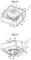
- Fig. 16 is an oblique view from above of the clip 1 in the temporary joined state of the main body 30 and the pin 10;
- Fig. 17 is an oblique view from below.
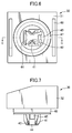
- Fig. 18 is a top view
- Fig. 19 is a front view
- Fig. 20 is a bottom view
- Fig. 21 is a right side view.
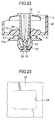
- Fig. 22 is a cross-sectional view along line A-A of Fig. 18 .
- the pin 10 and the main body 30 are temporarily joined, the pin 10 and the main body 30 are connected such that the latching claws 41 and support legs 44, 45 of the main body 30 go between the adjacent pin rotation regulation ribs 25 of the pin 10.
- the pin holding element 28 of the pin 10 heads into the central opening from the side walls 32 of the main body 30, and the pin 10 is inserted. At this time, the pin holding element 28 pushes apart the latching claws 41 of the main body 30.
- the space between the support legs 44, 45 is equal to or slightly larger than the diameter of the pin holding element 28, and, when the pin 10 is pushed into the main body 30, the support legs 44, 45 do not spread apart.
- the latching claws 41 When the pair of latching claws 41 spreads apart and the claw tips 42 ride over the pin holding element 28, the latching claws 41 close, and the claw tips 42 are positioned on both sides of the pin thin shaft 27. The lower ends of the latching claws 41 contact the pin holding element 28. This position is the temporary joined state. As shown in Fig. 21 , the lower ends of the latching claws 41 are in contact with the pin holding element 28, and the pin 10 is retained. As shown in Fig. 22 , the inside of the latching claws 41 are positioned while opening a gap with the tapering of the pin taper elements 26. A space is opened between the pin flange 11 of the pin 10 and the loop section 33 of the main body 30.
- the latching claws 41 of the main body 30 contact the pin rotation regulation ribs 25 of the pin 10, and the pin 10 and the main body 30 are regulated so that they do not rotate in relation to each other.
- Fig. 23 is a top view of part of the attaching hole 54 of the attached member 52.
- the shape of the attaching hole is a rectangle.
- the long side of the attaching hole 54 is in contact with the latching claws 41 and the short side with the support arms 44, 45.
- Fig. 24 is a cross-sectional view along the same cross-section as line A-A of Fig. 21 (temporary joined state) of the clip 21 in the primary joined state of the main body 30 and the pin 10.
- Fig. 25 is a cross-sectional view along the same cross-section as line E-E of Fig. 19 (temporary joined state) of the clip 1.
- Fig. 26 is an enlargement of the F element of Fig. 24 of the clip 1.
- the latching claws 41 and support arms 44, 45 of the main body of the clip 1 in the temporary joined state are inserted into the attaching hole 54 of the attached member 52 of a body panel or the like, so that they enter the attaching hole 54 of the attached member 52.
- the latching claws 41 run along the long side of the attaching hole 54, and the support legs 44, 45 along the short side.
- the contact element 48 on the underside of the bottom 31 of the main body 30 are in contact with the surface around the attaching hole 54 of the attached member 52. At this time, the edge 47a of the main body thin-walled flange 47 curves contacting the attached member 52.
- the attached member 52 is designated by a chain double-dashed line.
- the pin 10 is pushed down into the opening of the main body 30.
- the pin taper elements 26 of the pin 10 spread out the latching claws 41 of the main body 30, and the pin 10 moves down.
- the pair of latching claws 41 spread apart, and the claw tips 42 of the latching claws 41 clear the pin shaft latching convex element 24; joining with the pin shaft latching convex element 24, the pin 10 is retained.
- the claw tips 42 are spread out by the pin shaft planes 22, widening the distance.
- the distance between the opposing pair of support legs 44, 45 is greater than or equal to the diameter of the pin shaft 20. As shown in Fig. 24 , when the pin 10 is pushed into the opening of the main body 30, the support legs 44, 45 do not spread open. The support legs 44, 45 are in contact with the pin shaft top 21.
- the position of the pin flange 11 of the pin 10 and the central convex member 12 in the temporary joined state is shown by the chain double-dashed line in Fig. 25 .
- the pin 10 moves only by the distance St.
- the attached member 52 is fixed between the contact element 48 under the bottom 32 of the main body 30 and the spread-out latching claws 41, and the primary joined state occurs.
- the outer circumference 11 a of the pin flange 11 is in contact with the sloping element 34 so as to cover it.
- the configuration of the pin flange 11 in the temporary joined state is shown by a dotted line.
- the edge of the outer circumference 11a of the flange 11 is in contact with the sloping element 34 of the main body 30.
- the outer circumference 11 a of the flange 11 is pushed by the sloping element 34 of the main body 30 and curves upward.
- the outer circumference 11 a of the flange 11 and the sloping element 34 are in contact; a high degree of watertightness can be obtained.
- the distance in the height direction of the edge of the outer circumference 11 a and the top side of the bottom 31 is SF.
- main body thin-walled flange 47 in the temporary joined state is shown by a dotted line.
- the main body thin-walled flange 47 of the main body 30 comes in contact with the surface of the attached member 52 and bends; the height of the edge 47a of the main body thin-walled flange 47 from the underside of the bottom 31 is equal to the height of the contact elements 48.
- the bending amount of the edge 47a of the main body thin-walled flange 47 is the distance SG.
- the main body thin-walled flange 47 makes a seal between the main body 30 and the attached member 52, improving watertightness.
- Fig. 26 is an enlargement of the F element from Fig. 24 of the clip 1.
- the angle ⁇ 2 of the outer circumference 11 a of the pin flange 11 to the horizontal surface which is at the right angle to the central axis is greater than the angle ⁇ 1 of the sloping element 34 to the horizontal surface, and thus ⁇ 2 - ⁇ 1 is a smaller acute angle.
- the inner diameter of the edge of the outer circumference 11 a of the pin flange is smaller than the outer diameter of the sloping element 34 and greater than the inner diameter of the sloping element 34.
- the water penetration path of the clip 1 is shown by W2 in Fig. 25 . Since the clip 1 is constructed so that the outer circumference 11 a of the pin flange 11 covers over the sloping element 34, the water penetration path W2 is kinked up in an intricate manner, improving watertightness.
- F1' may be composed of force F2 (a vertical force on the sloping element 34) and the horizontal force F3. It is difficult for the outer circumference 11 a of the pin flange 11 to expand outwards by curving down in the approximate shape of a cylinder. For this reason, the pushing force of the pin flange 11 on the sloping element 34 is great enough so that a seal can actually be made between the pin flange 11 and the sloping element 34.
- the pin 10 and the main body 30 of the clip 1 are put in the primary joined state and fixed to the attached member 52, we shall now describe the method for removing the pin 10 and the main body 30.
- the pin 10 can be removed from the main body 30 by using a Phillips screwdriver, an everyday tool.
- the pin release leaves 14 of the pin 10 slide in contact over the release ribs 35 of the main body 30. Since the under side of the pin release leaves 14 are sloping surfaces, when rotating the pin 10 counterclockwise, the pin 10 is pushed up. When the pin 10 is rotated counterclockwise, the claw tips 42 move toward the pin shaft release elements 23 from the pin shaft planes 22, and the latching claws 41 spread further apart. The latching tips 42 release the connection with the pin latching convex element 24. The support legs 44, 45 are not joined to the shaft 20 of the pin 10. Subsequently, the pin 10 can be removed from the opening of the main body 30.
- the latching tips 42 move relatively under the pin latching convex element 24 and downward along the pin taper elements 26.
- the latching claws 41 are situated on the side of the pin taper elements 26 between the pin rotation regulation ribs 25 of the pin 10.
- the claw tips 42 are situated on the side of the pin thin shaft 27; when the lower end of the latching claws 41 come in contact with the pin holding element 28, the upward movement of the pin 10 stops. Thus, it returns to the temporary joined state shown in Fig. 16 , and can be used again. Furthermore, if the latching claws 41 are spread apart and the claws tips 42 are moved down beyond the pin holding element 28, the pin 10 can be completely removed from the main body 30.
- the bumper retainer is constructed in one piece with the main body 30. However, after constructing the bumper retainer as a separate element from the main body 30, the main body 30 may be fixed to the bumper retainer.
- the construction is such that the pin flange covers the inclined element; the direction in which the pin is pushed and the direction of the inclined element of the main body in which the pin flange is pressed are close in parallel. Because of this, sufficient watertightness can be achieved by pushing lightly. Further, because the outer circumference of the pin flange has a shape that curves it is hard for it to expand outward. Also, compared with a flat-shaped pin flange, there is little deformation such as rippling etc. and no dispersion of the watertightness function.
- attaching elements such as bumper retainers, protectors, brackets, etc. can be attached to an attached member of automobile body panel or the like by a light load.
- a clip having satisfactory watertightness can be obtained.
- a fastening structure that uses such a clip can be obtained.
Landscapes
- Engineering & Computer Science (AREA)
- General Engineering & Computer Science (AREA)
- Mechanical Engineering (AREA)
- Insertion Pins And Rivets (AREA)
Abstract
Description
- The invention pertains to a clip and member fastening structure used for installing attaching members such as bumper retainers, protectors or interior elements to attached members such as an automobile body panel and the like. More particularly, it pertains to a clip that fastens by pushing a pin into a main body and a member fastening structure that uses such a clip.
- Generally, clips are used to install attaching members such as bumper retainers, protectors or interior elements to attached members such as an automobile body panel or the like. Several clips are known that consist of a combination of a pin and a main body (grommet), press fit the pin into an opening of the torso of the main body and, while expanding a latching claw equipped on the torso, latch on the attaching hole of the attached member.
- This type of clip can install the attaching member to the attached member simply just by pushing the pin into the hollow space of the main body. The clip is also such that, after joining the pin and the main body, the pin and the main body may be detached by rotating the pin. However, in order for the clip of prior art to latch the pin onto the main body reliably, it is necessary to apply strong weight when pushing the pin into the main body. Also, sealing between the pin and main body is not sufficient so it cannot be used as a part if watertightness is required.
-
Patent Reference 1 concerns a clip that improves watertightness between the pin and main body of the clip.Figure 1A is a cross-sectional drawing running along the central axis of the clip ofPatent Reference 1;Fig. 1B is a cross-sectional drawing of the perpendicular toFig. 1A . The clip ofPatent Reference 1 is provided with apin 5 and agrommet 4. Thegrommet 4 constitutes an element of a bumper retainer and the clip is attached to a base 2 (attached member) by insertion of thepin 5 into a lead-through hole of thegrommet 4. - The
grommet 4 has a jaw-like element 7 in contact with thebase 2 and aleg 8 that extends down from the jaw-like element 7. Theleg 8 has one pair offirst leg elements 8a facing both sides of the central axis and one pair ofsecond leg elements 8b at right angles with thefirst leg elements 8a. Thepin 5 has ahead 5a, a thin-walled flange 5b extending outward from thehead 5a and ashaft 9 extending down from thehead 5a. - To attach the clip, the leg of the
grommet 4 is inserted into the center hole of thepacking 6. Theshaft 9 of thepin 5 is inserted into the opening of thegrommet 4 and then joined with thepin 5. While temporarily joined, the ends of thesecond leg elements 8b of thegrommet 4 interpose thethin diameter element 9b of theshaft 9 of thepin 5. Thefirst leg elements 8a of thegrommet 4 are positioned on both sides of thecam 9c element of theshaft 9. - Then, when the
head 5a of thepin 5 is pushed into thegrommet 4, thethick diameter element 9a of theshaft 9 pushes thefirst leg element 8a of thegrommet 4 open (Fig. 1 B) . Thebase 2 is interposed between the bottom of the jaw-like element 7 and the expanded pair offirst leg elements 8a and installed. Theend 8d of thesecond leg element 8b of thegrommet 4 is put into theconvex element 9d of theshaft 9 of the pin 5 (Fig. 1A ), and theshaft 9 of thepin 5 is fixed so that it does not move in an axial direction vis-a-vis thegrommet 4. - In
Patent Reference 1, theflange 5a of thepin 5 is in contact with the projectingwall element 7b on top of the jaw-like element 7 of thegrommet 4 and curving in the opposite direction. Because the fastening structure ofPatent Reference 1 is closely attached between theflange 5b of thepin 5 and the jaw-like element 7 of thegrommet 4, sealing and durability are improved. - In order to improve watertightness between the
pin 5 and thegrommet 4, it is necessary to push theflange 5b forcibly into thewall element 7b. As shown inFig. 1A , for the clip ofPatent Reference 1, the force F1 on thepin 5 and the force F2 pushing theflange 5b onto thewall element 7b are the same. Therefore, in order to improve watertightness, the force F1 pushing thepin 5 must be great because the force F2 pushing theflange 5b onto thewall element 7b is great. If the adherence between theflange 5b and thewall element 7b is insufficient, water may possibly enter from the penetration path shown at W1. -
Patent Reference 2 discloses a clip comprising a male member (pin) having a shaft and a head provided on the tip of the shaft; and a female member (main body) having latching leg elements that deform elastically on the outside pushed by the shaft, and clicking leg elements formed with a claw engaging with a corresponding hole formed on the shaft. - The clip of
Patent Reference 2 obtains a coercive force after installation by means of the latching leg elements, and, when the clip is installed, a clicking sensitivity is achieved by means of the clicking leg elements; so both sufficient coercive force and sufficient clicking sensitivity are obtained. However, with the clip ofPatent Reference 2, even after it is attached, a gap opens between the head of the male member and ring element of the pedestal of the female member, so that water may possibly penetrate from this gap. Because watertightness was not carefully considered for the clip ofPatent Reference 2, it cannot be utilized when watertightness is a requirement. - For this reason, a clip that can push a pin using little weight and that has suitable water-tightness has been sought. The fastening structure elements that use such a clip have also been sought.
-
- Patent Reference 1:
JP 2011 202692 A - Patent Reference 2:
JP 2009 41673 A - Consequently, the object of the invention is to provide a clip that can push a pin using little weight and that has suitable watertightness. Another object of the invention is to provide the fastening structure that uses such a clip.
- In order to achieve this object, the first aspect of the invention is a clip comprising a pin and a main body having an opening for insertion of the pin; characterized in that the pin has a pin flange and a pin shaft extending down from the pin flange, and outer circumference of the pin flange curves downward; the main body has a bottom, a pair of latching claws extending downward from the bottom along the opening, an annular loop section on the upper side of the bottom and a sloping element the height of which gradually decrease from the outside of the loop section to the bottom; and the inner diameter of the outer circumference of the pin flange of the pin is greater than the inner diameter of the sloping element of the main body and smaller than the outer diameter thereof.
- If the outer circumference of the pin flange curves downward, the rigidity of the pin flange increases, and there are fewer deformations such as corrugation. If the inner diameter of the edge of the outer circumference of the pin flange of the pin is greater than the inner diameter of the sloping element of the main body and smaller than the outer diameter, in the primary joined state, the effect of watertightness increases because the edge of the outer circumference of the pin flange is in contact with the sloping element.
- Preferably, the pin flange has elasticity, and the angle made by the outer circumference of the pin flange with the horizontal plane that is perpendicular to the central axis of the pin is greater than the angle made by the sloping element makes with the horizontal plane.
- If the pin flange has elasticity and the angle that the outer circumference of the pin flange forms with the horizontal plane is greater than the angle the sloping element forms with the horizontal plane, the effect of watertightness is enhanced, because the edge of the outer circumference is in contact with the sloping element of the main body. Because the difference between the angle of the outer circumference of the pin flange and the angle of the sloping element is small, it is difficult for the outer circumference of the pin flange to expand. For this reason, even if the load pushing on the pin is slight, there is sufficient contact pushing the outer circumference of the pin flange on the sloping element of the main body.
- Preferably, the main body has support legs extending down from the bottom between the pair of latch claws extending along the opening.
- If the main body has support legs extending down from the bottom between the latching claws, the pin can be guided into the opening formed by the latch claws and the support legs corresponding to the direction of the pin. Also, corresponding to the direction of the pin, the latch claws and support legs can be inserted into the attaching hole of the attached member.
- The main body preferably has an annular main body thin-walled flange that is easy to curve around the opening on the lower side of the bottom, and contact elements around the main body thin-walled flange, and wherein, in the primary joined situation, the main body thin-walled flange being curved, the edge of the main body thin-walled flange is preferably in contact with the surface of the attached member. The lower faces of the contact elements should be in contact with the surface of the attached member.
- In the primary joined situation, the main body thin-walled flange curved, when the edge of the main body thin-walled flange is in contact with the surface of the attached member, there is a hermetic seal between the main body and the attached member, and, thus, there is little concern of water penetrating.
- The pin shaft preferably has a cylindrical pin shaft top, pin shaft planes which are longitudinal planes provided at equal intervals circumferentially below the pin shaft top, pin shaft release elements with a curved surface between the adjacent pin shaft planes, and a short cylindrical pin shaft latching convex element under the pin shaft planes.
- If the pin has pin shaft planes and a pin latching convex element, when the pin is inserted into the main body, the legs of the latching claws spread, the claw tips of the latching claws come in contact with the pin latching convex element, and the pin is prevented from falling out. The attached member can be fixed between the attaching bases of the latching claws with legs spread and the contact elements. If the pin has pin shaft release elements, letting the pin rotate and the claw tips of the latching claws contact the pin shaft release elements, the joining with the pin latching convex element can be disengaged.
- Furthermore, the pin shaft preferably has pin rotation regulation ribs provided at equal intervals in a circumferential direction under the pin shaft release elements; pin taper elements tapering downward provided between the adjacent pin rotation regulation ribs; a narrow cylindrical pin thin shaft under the pin rotation regulation ribs; and a disc shaped pin holding element under the pin thin shaft.
- If there are pin rotation regulation ribs, the insertion direction of the pin vis-a-vis the main body can be regulated. If there is a cylindrical pin thin shaft, the latching claws can be placed adjacent to the pin thin shaft and be kept in a temporary joined state in which the latching claws are not spread apart. If there is a disc shaped pin holding element, the lower ends of the latching claws are in contact with the pin holding element, and the pin can be stopped from falling out.
- Preferably, in the temporary joined state, the latching claws of the main body are in contact with the pin rotation regulation ribs of the pin, and the pin is regulated so as not to rotate vis-a-vis the main body.
- In the state in which the latching claws of the main body are in contact with the pin rotation regulation ribs of the pin, when the pin is pushed into the main body, the latching claws of the main body are in a position contacting the pin shaft planes, and the primary joined state is easily obtained.
- Preferably, in the temporary joined state, the lower ends of the latching claws of the main body are in contact with the pin holding element of the pin, and the pin is retained so as not to be pulled out from the main body; the pair of latching claws of the main body are adjacent to the pin taper elements, and the pin is supported so as not to be pushed into the main body accidentally.
- In the temporary joined state, the pin cannot become disconnected from the main body or be pushed into the main body accidentally, and the temporary joined state can be maintained in a stable manner.
- Preferably, in the primary joined state, the latching claws are spread apart, and the crew tips of the latching claws are joined to the pin shaft latching convex element; the pin is stopped from being pulled out, and the attached member is held between the attaching bases of the latching claws and the contact elements.
- When the latching claws are spread apart, and the clip is prevented from falling off, the attached member being held between the attaching bases of the latching claws and the contact elements, and it is not easy to disconnect them. Because support legs do not deform in the primary joined state, the support legs can have the function of guiding the pin in the direction of the opening. If the edge of the outer circumference of the pin flange is in contact with the sloping element, the effect of watertightness is enhanced.
- Preferably, the pin has several sloping pin release leaves at the underside of the pin flange and around the pin shaft top, the main body has several release ribs between the loop section and the opening, in the primary joined state, if the pin is caused to rotate, the pin release leaves are pushed up by the release ribs of the main body, the claw tips of the latching claws of the pin shift from the pin shaft planes of the main body to the pin shaft release elements, the latching claws spread further, the joint of the crew tips with the pin latching convex element of the claw tips is released, the pin shaft can be released within the opening, and it returns to the temporary joined state.
- If the pin has several sloping pin release leaves around the pin shaft top below the pin flange of the pin, and the main body has several release ribs between the ring element and the opening, the main body and the pin may easily return to the temporary joined state by rotating the pin. When the main body and the pin return to the temporary joined state, they can be used again.
- A second aspect of the invention is a pin in a clip comprising the pin and a main body having an opening for inserting the pin; characterized in that the pin has an elastic pin flange and a pin shaft that extends downward from the pin flange, and the outer circumference of the pin flange curves downward; the pin shaft has a cylindrical pin shaft top; pin shaft planes which are longitudinal planes provided at equal intervals in the circumferential direction below the pin shaft top; curved pin shaft release elements between the adjacent pin shaft planes; and a short cylindrical pin shaft latching convex element under the pin shaft planes.
- A third aspect of the invention is the main body used in a clip comprising a pin and the main body having an opening for inserting the pin characterized in that; the main body has a bottom, a pair of latching claws extending downward from the bottom and along the opening, an annular loop section on the upper side of the bottom, a sloping element the height of which becomes gradually lower from the outside of the loop section to the bottom, and support legs extending downward from the bottom between a pair of latching claws extending along the opening.
- A fourth aspect of the invention is a clip in which the pin and the main body having an opening for inserting the pin are in a temporary joined state; characterized in that the pin has a pin flange and a pin shaft extending down from the pin flange, and outer circumference of the pin flange curves downward; the main body has a bottom, a pair of latching claws extending downward from the bottom along the opening, an annular loop section on the upper side of the bottom, and a sloping element the height of which gradually decreases from the outside of the loop section to the bottom; the pin shaft of the pin has pin rotation regulation ribs provided at equal intervals in a circumferential direction; and the latching claws of the main body are in contact with pin rotation regulation ribs of the pin, the pin is regulated so as not to rotate vis-a-vis the main body.
- The clip, in which the pin and the main body are in a temporary joined state, can be inserted into the attaching hole of the attached member, and can be lead into the primary joined state, and the clip can be fastened to the attached member.
- A fifth aspect of the invention is a fastening structure wherein a clip comprising a pin and a main body having an opening for inserting the pin into the attaching hole of an attached member is fastened to the attaching hole of the attached member; characterized in that the pin has a pin flange and a pin shaft extending downward from the pin flange, and the outer circumference of the pin flange curves downward; the main body has a bottom, a pair of latching claws extending downward from the bottom along the opening; an annular loop section on the upper side of the bottom and a sloping element, the height of which gradually decreases from the outside of the loop section to the bottom and two parallel rod-like contact elements on the lower side of the bottom; wherein the edge of the outer circumference of the pin flange is in contact with the sloping elements of the main body, the latching claws of the main body spread apart, and the claw tips of the latching claws connect to the pin shaft of the pin, and the attached member is held between the attaching bases of the latching claws and contact elements of the main body.
- In accordance with the present invention, a clip is proposed that can push a pin using little weight and having satisfactory watertightness. A member fastening structure using such a clip is also proposed.
-
- Fig. 1A
- is a cross-sectional view along the central axis of the fastening structure of prior art.
- Fig. 1B
- is a cross-sectional view perpendicular to
Fig. 1A of the fastening structure of prior art. - Fig. 2
- is an oblique view from above of the main body of the clip according to the embodiment of the invention.
- Fig. 3
- is an oblique view from below of the main body of
Fig. 2 . - Fig. 4
- is a top view of the main body of
Fig. 2 . - Fig. 5
- is a front view of the main body of
Fig. 2 . - Fig. 6
- is a bottom view of the main body of
Fig. 2 - Fig. 7
- is a right-side view of the main body of
Fig. 2 . - Fig. 8
- is a cross-sectional view along line D-D of
Fig. 6 of the main body ofFig. 2 . - Fig. 9
- is an oblique view from above of the pin of the clip according to the embodiment of the invention.
- Fig. 10
- is an oblique view from below of the pin of
Fig. 9 . - Fig. 11
- is a top view of the pin of
Fig. 9 . - Fig. 12
- is a front view of the pin of
Fig. 9 . - Fig. 13
- is a bottom view of the pin of
Fig. 9 . - Fig. 14
- is a cross-sectional view along line A-A of
Fig. 11 of the pin ofFig. 9 . - Fig. 15
- is a cross-sectional view along line B-B of the
Fig. 12 of the pin ofFig. 9 . - Fig. 16
- is an oblique view from above of the clip in the temporary joined state of the main body of
Fig. 2 and the pin ofFig. 9 . - Fig. 17
- is an oblique view from below of the clip of
Fig. 16 . - Fig. 18
- is a top view of the clip of
Fig. 16 . - Fig. 19
- is a front view of the clip of
Fig. 16 . - Fig. 20
- is a bottom view of the clip of
Fig. 16 . - Fig. 21
- is a right side view of the clip of
Fig. 16 . - Fig. 22
- is a cross-sectional view along line A-A of
Fig. 18 of the clip ofFig. 16 . - Fig. 23
- is a top view of the attaching hole of the attaching member.
- Fig. 24
- is a cross sectional view along the same cross section A-A of
Fig. 21 of the clip in the primary joined state. - Fig. 25
- is a cross-sectional view along the same cross section E-E of
Fig. 19 of the clip ofFig. 24 . - Fig. 26
- is an enlarged view of the F part of the clip of
Fig. 24 . - An embodiment of the invention will be described in the following, with reference to the drawings. According to an embodiment of the invention, the
clip 1 consists of themain body 30 made of plastic shown inFigs. 2 to 8 and thepin 10 made of plastic shown inFigs. 9 to 15 . When thepin 10 is pushed into the opening of themain body 30, the temporary joined state shown inFigs. 16 to 22 is ensured. By inserting theclip 1 of the temporary joined state to the attachinghole 54 of the attachedmember 52 and pushing thepin 10 further into themain body 30, the primary joined state shown inFigs. 24 to 26 is achieved, and theclip 1 is attached to the attachedmember 52. In the description of this Specification, the central axis of thepin 10 is designated as the central axis and the direction of the central axis of thepin 10 as the vertical direction. The surface orthogonal to the central axis is designated as the horizontal surface. - The
clip 1 is used to install attaching members such as a bumper retainer, protector, protective cover, bracket, etc. to an attachedmember 52 such as an automobile body panel. In the embodiment of the invention, themain body 30 of theclip 10 constitutes one element of a bumper retainer. Alternatively, themain body 30 may constitute a separate element with a bumper retainer, and themain body 30 may be fixed to the bumper retainer. - The
main body 30 shall be described with reference toFigs. 2 to 8 .Fig. 2 is an oblique view showing themain body 30 of theclip 1 according to the embodiment of the invention from above, andFig. 3 is an oblique view from below.Fig. 4 is a top view,Fig. 5 is a front view,Fig. 6 is a bottom view andFig. 7 is a right-side view.Fig. 8 is a cross-sectional view along line D-D ofFig. 6 . - As shown in
Figs. 2 and 3 , themain body 30 on the exterior has a nearly square bottom 31 andside walls 32 extending upward from the each edge of the bottom 31. The upper surface of the bottom 31 is surrounded by fourside walls 32. In the embodiment of the invention, themain body 30 is one element of the bumper retainer, and the bumper retainer is extended to the sides of the side walls 32 (not shown in the drawing). The shape of theside walls 32 may be changed to correspond to the shape of the bumper retainer. There may not even be any side walls, depending on the shape of the bumper retainer. - The center of the bottom 31 is provided with an opening to receive the
pin 10 to be described below. Anannular loop section 33 is provided around the opening on the surface of the bottom 31. Theloop section 33 has a fixed width and a fixed height. The outer circumference of theloop section 33 is asloping element 34 that slants from the height of theloop section 33 to the bottom 31 in a radial direction. The inner diameter of the edge of theouter circumference 11 a of thepin flange 11 of thepin 10 is greater than the inner diameter of the slopingelement 34 and smaller than the outer diameter. Thepin flange 11 covers the slopingelement 34 so that the edge of theouter circumference 11 a of thepin flange 11 is in contact with the slopingelement 34. - As shown in
Figs. 2 and4 , between the inside of theloop section 33 and the opening, a pair of facingrelease ribs 35 is provided. The height of therelease ribs 35 gradually increases from theloop section 33 to the central axis. As to be described below, therelease ribs 35 are used to detach thepin 10. - Where there are no
release ribs 35 between the inside of theloop section 33 and the opening, loopsection reinforcement ribs 36 are provided. The height of the loopsection reinforcement ribs 36 gradually decreases from theloop section 33 to the opening. Three loopsection reinforcement ribs 36 are provided on one side of the circumference between the pair ofrelease ribs 35 and three on the other side at equal intervals. The loop section reinforcement ribs are provided along theloop section 33 and reinforce theloop section 33. The shape and number of loopsection reinforcement ribs 36 may be different from those shown in the embodiment. - As shown in
Fig. 3 , on the under side of the bottom 31, a pair of latchingclaws 41 extend downward through the opening. As shown inFig. 7 , the latchingclaws 41 become thicker as they go descend. The latchingclaws 41 are pushed by thepin shaft 20 of thepin 10 and can be spread apart. The spreading occurs by opening the tips of the pair of latchingclaws 41 so that they separate from each other. In the primary joined state, the attachingbases 41 a of the latchingclaws 41 is joined to the attachinghole 54 of the attachedmember 52. Since the latchingclaws 41 are spread apart, the attached member can be held. - From near the lower ends of each latching
claws 41, theclaw tips 42 project inward towards the central axis. In the primary joined state, theclaw tips 42 are joined to the pin latchingconvex element 24 of the pin 10 (Fig. 25 ). - As shown in
Fig. 8 , which is a cross-sectional drawing along line D-D ofFigs. 5 and6 , at right angles to the pair of latchingclaws 41, a pair ofsupport legs support leg 44 on one side is wide and has nearly the same length as the latchingclaw 41. As shown inFig. 6 , the exterior surface away from the central axis of thesupport leg 44 is nearly level, and its interior surface near the central axis has an arc shape in its cross section in order to conform to thepin shaft 20 of thepin 10. - The
other support leg 45 is not as wide as thesupport leg 44; it is also shorter in length. The exterior away from the central axis of thesupport leg 45 is nearly level, and its interior near the central axis has a convex shape in order to conform to thepin shaft 20 of thepin 10. In the embodiment of the invention, the shapes of onesupport leg 44 and of theother support leg 45 are different. The shapes of the support legs are not limited to those shown in the embodiment. The shapes of thesupport legs support legs hole 54 of the attachedmember 52 and to guide thepin shaft 20 into the inside opening of thesupport legs - The cross-sectional exterior connecting the pair of latching
claws 41 and thesupport legs hole 54 of the attachedmember 52. The pair of latchingclaws 41 andsupport legs hole 54 of the attachedmember 52. Also, the opening of themain body 30 is an empty space surrounded by the pair of latchingclaws 41 and thesupport legs pin 20 of thepin 10 is to be guided into the opening of themain body 30. The space between thesupport legs pin shaft top 21 of thepin shaft 20. Thesupport legs pin 10 into the opening of themain body 30, as they do not spread apart in the temporary joined state or the primary joined state. Thesupport legs member 52. - As shown in
Figs. 5 and6 , there is a main body thin-walled flange 47 on the underside of the bottom 31 around the opening; it extends down to widen towards the outside. Since the main body thin-walled flange 47 is a thin wall and -- looking at the cross section -- it ripples, it bends easily. In the fixed state of theclip 1 to the attachedmember 52, the main body thin-walled flange curves to contact the surface of the attachedmember 52 and makes a seal between the main body and the attachedmember 52; thus maintaining watertightness. - On the underside of the bottom 31, a pair of opposing
contact elements 48 extend in a straight line horizontally along the edge of the bottom. The height of thecontact elements 48 is uniform. Thecontact elements 48, when in the state of being fixed to the attachedmember 52, hold theclip 1 at a uniform distance between the bottom 31 of themain body 30 and the attachedmember 52. Theedge 47a of the main body thin-walled flange 47 is pushed to the same height as that ofcontact elements 48, contacting the surface of the attachedmember 52 and making a seal. Thecontact elements 48 prevent the crushing of main body thin-walled flange, thus maintaining watertightness. - The
pin 10 will be described with reference toFigs. 9 to 15 .Fig. 9 is an oblique view of thepin 10 of theclip 1 from above, andFig. 10 an oblique view from below, according to the embodiment of the invention.Fig. 11 is a top view,Fig. 12 is a front view,Fig. 13 is a bottom view,Fig. 14 is a cross-sectional view along line A-A ofFig. 11 ;Fig. 15 is a cross-sectional view along line B-B ofFig. 12 . Thepin 10 has acylindrical pin flange 11 at its upper portion and apin shaft 20 extending down from thepin flange 11. Thepin flange 11 has anouter circumference 11 a in a shape that curves downward and is highly rigid. Also, theouter circumference 11 a can cover and overlap the slopingelement 34 of themain body 30; therefore, a high level of watertightness can be achieved. - As shown in
Fig. 9 , the center of thepin flange 11 is a centralconvex element 12, and its cylindrical surface is a step higher than thepin flange 11. Across-shaped slot 13 is formed on the centralconvex element 12. By inserting the tip of a screwdriver into thecross-shaped slot 13 and rotating thepin 10, thepin 10 may be removed from themain body 30. - As shown in
Fig. 10 , four pin release leaves 14 are disposed at an equal distance around thepin shaft 10 below thepin flange 11. The pin release leaves 14 have a uniform radial thickness, the outer surface is in the shape of a right triangle, and the under side is a sloping surface. This sloping surface has a height that gradually decreases in a circumferential direction. When thepin 10 is rotated in a counter clockwise direction to be removed, the sloping surfaces of pin release leaves 14 slides into contact on therelease ribs 35 of themain body 30, and thepin 10 is pushed up. - As shown in
Figs. 10 and12 , thepin shaft 20 extends along the central axis under the centralconvex element 12. Thepin shaft 20 includes apin shaft top 21, pin shaft planes 22, a pinshaft release elements 23, a pin latchingconvex element 24, pinrotation regulation ribs 25,pin taper elements 26, a pinthin shaft 27 and apin holding element 28. As shown inFig. 14 , thecross-shaped slot 13 is disposed deeply into thepin taper elements 26 of thepin shaft 20. - The
pin shaft top 21 situated at the highest element of thepin shaft 20 is cylindrical. Below thepin shaft top 21, four rectangular pin shaft planes 22 are disposed circumferentially at equal intervals. A circular surfaced pinshaft release element 23 is between two adjacent pin shaft planes 22. As shown inFig. 15 , a cross-sectional view along line B-B ofFig. 12 , the pin shaft planes 22 and the pinshaft release elements 23 are disposed, alternating with each other. Below the pin shaft planes 22, there is a cylindrical pin latchingconvex element 24 having a short length. The outer diameter of the pinshaft release elements 23 is nearly the same in diameter as thepin shaft top 21 and the pin latchingconvex element 24. - In the primary joined state, the latching
tips 42 of the latchingclaws 41 of themain body 30 are in contact with the pin latchingconvex elements 24, and thepin 10 is held so as not to be removed. When removing thepin 10, thepin 10 is rotated, and latchingtips 42 strike into the pinshaft release elements 23 from the pin shaft planes 22. Because the surfaces of the pinshaft release elements 23 and the pin latchingconvex elements 24 are connected, the latchingclaws 42 release their contact with the pin latchingconvex elements 24, and thepin 10 can be removed from the opening into the temporary joined state. - Under the pin latching
convex elements 24, four pinrotation regulation ribs 25 in the form of thin plates extend vertically at equal distances in a radial direction. The angle position around the central axis of the pinrotation regulation ribs 25 is the same as the angle position of the pinshaft release elements 23. The elements between the adjacent pin latchingconvex elements 24 are thepin taper elements 26 with their tapering gradually narrowing downward. - In the temporary joined state of the
main body 30 and thepin 10, the pinrotation regulation ribs 25 regulate the relative position of thepin 10 vis-a-vis themain body 30 by having each of the latchingclaws 41 andsupport legs rotation regulation ribs 25. In this state, when thepin 10 is pushed into the opening of themain body 30, theclaw tips 42 of the pair of latchingclaws 41 move along thepin taper elements 26 and gradually spread apart. When the pair ofclaw tips 42 go up from the pin latchingconvex elements 24, they join the pin latchingconvex elements 24, and thepin 10 is retained. - Under the pin
rotation regulation ribs 25 and thepin taper elements 26 is a narrow cylindrical pinthin shaft 27. The tip of thepin shaft 20 under the pinthin shaft 27 is a circular diskpin holding element 28 of greater diameter than the pinthin shaft 27. The diameter of thepin holding element 28 is nearly equal to the diameters of thepin shaft top 21, the pinshaft release elements 23 and the pin latchingconvex elements 24. - In the temporary joined state, the
claw tips 42 of the latchingclaws 41 of themain body 30 come in contact with the top of thepin holding element 28 and hold thepin 10 so that it does not become removed from themain body 30. Also, the latchingclaws 41 are positioned around thepin taper elements 26. If thepin 10 is pushed with strong force, thepin taper elements 26 spreads out the latchingclaws 41, and theshaft 20 of thepin 10 enters into the opening of themain body 30. - Generally, the
clip 1 keeps the setup of themain body 30 and thepin 10 in the temporary joined state and is supplied to the assembling division.Fig. 16 is an oblique view from above of theclip 1 in the temporary joined state of themain body 30 and thepin 10;Fig. 17 is an oblique view from below.Fig. 18 is a top view,Fig. 19 is a front view,Fig. 20 is a bottom view andFig. 21 is a right side view.Fig. 22 is a cross-sectional view along line A-A ofFig. 18 . - When the
pin 10 and themain body 30 are temporarily joined, thepin 10 and themain body 30 are connected such that the latchingclaws 41 andsupport legs main body 30 go between the adjacent pinrotation regulation ribs 25 of thepin 10. Thepin holding element 28 of thepin 10 heads into the central opening from theside walls 32 of themain body 30, and thepin 10 is inserted. At this time, thepin holding element 28 pushes apart the latchingclaws 41 of themain body 30. The space between thesupport legs pin holding element 28, and, when thepin 10 is pushed into themain body 30, thesupport legs - When the pair of latching
claws 41 spreads apart and theclaw tips 42 ride over thepin holding element 28, the latchingclaws 41 close, and theclaw tips 42 are positioned on both sides of the pinthin shaft 27. The lower ends of the latchingclaws 41 contact thepin holding element 28. This position is the temporary joined state. As shown inFig. 21 , the lower ends of the latchingclaws 41 are in contact with thepin holding element 28, and thepin 10 is retained. As shown inFig. 22 , the inside of the latchingclaws 41 are positioned while opening a gap with the tapering of thepin taper elements 26. A space is opened between thepin flange 11 of thepin 10 and theloop section 33 of themain body 30. - In the temporary joined state, if one is to push the
pin 10 further, great force is necessary to push it, since the latchingclaws 41 are pushed to open wide by thepin taper elements 26. For this reason, incorrectly pushing into the primary joined state can be prevented. - In the temporary joined state, the latching
claws 41 of themain body 30 contact the pinrotation regulation ribs 25 of thepin 10, and thepin 10 and themain body 30 are regulated so that they do not rotate in relation to each other. -
Fig. 23 is a top view of part of the attachinghole 54 of the attachedmember 52. The shape of the attaching hole is a rectangle. The long side of the attachinghole 54 is in contact with the latchingclaws 41 and the short side with thesupport arms -
Fig. 24 is a cross-sectional view along the same cross-section as line A-A ofFig. 21 (temporary joined state) of theclip 21 in the primary joined state of themain body 30 and thepin 10. -
Fig. 25 is a cross-sectional view along the same cross-section as line E-E ofFig. 19 (temporary joined state) of theclip 1.Fig. 26 is an enlargement of the F element ofFig. 24 of theclip 1. - To move to the primary joined state from the temporary joined state of the
clip 1, the latchingclaws 41 andsupport arms clip 1 in the temporary joined state are inserted into the attachinghole 54 of the attachedmember 52 of a body panel or the like, so that they enter the attachinghole 54 of the attachedmember 52. The latchingclaws 41 run along the long side of the attachinghole 54, and thesupport legs contact element 48 on the underside of the bottom 31 of themain body 30 are in contact with the surface around the attachinghole 54 of the attachedmember 52. At this time, theedge 47a of the main body thin-walled flange 47 curves contacting the attachedmember 52. The attachedmember 52 is designated by a chain double-dashed line. - Next, the
pin 10 is pushed down into the opening of themain body 30. Thepin taper elements 26 of thepin 10 spread out the latchingclaws 41 of themain body 30, and thepin 10 moves down. As shown inFig. 25 , the pair of latchingclaws 41 spread apart, and theclaw tips 42 of the latchingclaws 41 clear the pin shaft latchingconvex element 24; joining with the pin shaft latchingconvex element 24, thepin 10 is retained. Theclaw tips 42 are spread out by the pin shaft planes 22, widening the distance. - The distance between the opposing pair of
support legs pin shaft 20. As shown inFig. 24 , when thepin 10 is pushed into the opening of themain body 30, thesupport legs support legs pin shaft top 21. - The position of the
pin flange 11 of thepin 10 and the centralconvex member 12 in the temporary joined state is shown by the chain double-dashed line inFig. 25 . When the primary joined state comes out of the temporary joined state, thepin 10 moves only by the distance St. As shown inFig. 25 , the attachedmember 52 is fixed between thecontact element 48 under the bottom 32 of themain body 30 and the spread-out latchingclaws 41, and the primary joined state occurs. In the primary joined state, theouter circumference 11 a of thepin flange 11 is in contact with the slopingelement 34 so as to cover it. - The configuration of the
pin flange 11 in the temporary joined state is shown by a dotted line. In the primary joined state, the edge of theouter circumference 11a of theflange 11 is in contact with the slopingelement 34 of themain body 30. Theouter circumference 11 a of theflange 11 is pushed by the slopingelement 34 of themain body 30 and curves upward. Theouter circumference 11 a of theflange 11 and the slopingelement 34 are in contact; a high degree of watertightness can be obtained. The distance in the height direction of the edge of theouter circumference 11 a and the top side of the bottom 31 is SF. - The configuration of main body thin-
walled flange 47 in the temporary joined state is shown by a dotted line. In the primary joined state, the main body thin-walled flange 47 of themain body 30 comes in contact with the surface of the attachedmember 52 and bends; the height of theedge 47a of the main body thin-walled flange 47 from the underside of the bottom 31 is equal to the height of thecontact elements 48. The bending amount of theedge 47a of the main body thin-walled flange 47 is the distance SG. The main body thin-walled flange 47 makes a seal between themain body 30 and the attachedmember 52, improving watertightness. -
Fig. 26 is an enlargement of the F element fromFig. 24 of theclip 1. Referring toFigs. 24 and26 , theangle θ 2 of theouter circumference 11 a of thepin flange 11 to the horizontal surface which is at the right angle to the central axis is greater than theangle θ 1 of the slopingelement 34 to the horizontal surface, and thus θ2 - θ1 is a smaller acute angle. The inner diameter of the edge of theouter circumference 11 a of the pin flange is smaller than the outer diameter of the slopingelement 34 and greater than the inner diameter of the slopingelement 34. Since the direction of the slopingelement 34 and the direction of theouter circumference 11 a of thepin flange 11 is close on a parallel, the edge of theouter circumference 11a of thepin flange 11 comes in contact with the slopingelement 34 at a small angle, improving watertightness.
The water penetration path of theclip 1 is shown by W2 inFig. 25 . Since theclip 1 is constructed so that theouter circumference 11 a of thepin flange 11 covers over the slopingelement 34, the water penetration path W2 is kinked up in an intricate manner, improving watertightness. - If the
pin 10 is pushed down with force F1, the edge of theouter circumference 11a of thepin flange 11 pushes the slopingelement 34 down with the force F1' of the same magnitude as F1. F1' may be composed of force F2 (a vertical force on the sloping element 34) and the horizontal force F3. It is difficult for theouter circumference 11 a of thepin flange 11 to expand outwards by curving down in the approximate shape of a cylinder. For this reason, the pushing force of thepin flange 11 on the slopingelement 34 is great enough so that a seal can actually be made between thepin flange 11 and the slopingelement 34. - Once the
pin 10 and themain body 30 of theclip 1 are put in the primary joined state and fixed to the attachedmember 52, we shall now describe the method for removing thepin 10 and themain body 30. Thepin 10 can be removed from themain body 30 by using a Phillips screwdriver, an everyday tool. - When the
pin 1 is rotated by inserting the tip of a Phillips screwdriver into thecross-shaped slot 13 of thepin 1 of theclip 10 in the primary joined state, the pin release leaves 14 of thepin 10 slide in contact over therelease ribs 35 of themain body 30. Since the under side of the pin release leaves 14 are sloping surfaces, when rotating thepin 10 counterclockwise, thepin 10 is pushed up. When thepin 10 is rotated counterclockwise, theclaw tips 42 move toward the pinshaft release elements 23 from the pin shaft planes 22, and the latchingclaws 41 spread further apart. The latchingtips 42 release the connection with the pin latchingconvex element 24. Thesupport legs shaft 20 of thepin 10. Subsequently, thepin 10 can be removed from the opening of themain body 30. - When the
pin 10 moves upward, the latchingtips 42 move relatively under the pin latchingconvex element 24 and downward along thepin taper elements 26. The latchingclaws 41 are situated on the side of thepin taper elements 26 between the pinrotation regulation ribs 25 of thepin 10. Theclaw tips 42 are situated on the side of the pinthin shaft 27; when the lower end of the latchingclaws 41 come in contact with thepin holding element 28, the upward movement of thepin 10 stops. Thus, it returns to the temporary joined state shown inFig. 16 , and can be used again. Furthermore, if the latchingclaws 41 are spread apart and theclaws tips 42 are moved down beyond thepin holding element 28, thepin 10 can be completely removed from themain body 30. - In the embodiment of the invention, the bumper retainer is constructed in one piece with the
main body 30. However, after constructing the bumper retainer as a separate element from themain body 30, themain body 30 may be fixed to the bumper retainer. - According to the embodiment of the invention, the construction is such that the pin flange covers the inclined element; the direction in which the pin is pushed and the direction of the inclined element of the main body in which the pin flange is pressed are close in parallel. Because of this, sufficient watertightness can be achieved by pushing lightly. Further, because the outer circumference of the pin flange has a shape that curves it is hard for it to expand outward. Also, compared with a flat-shaped pin flange, there is little deformation such as rippling etc. and no dispersion of the watertightness function.
- According to the embodiment of the invention, attaching elements such as bumper retainers, protectors, brackets, etc. can be attached to an attached member of automobile body panel or the like by a light load. In addition, a clip having satisfactory watertightness can be obtained. Further, a fastening structure that uses such a clip can be obtained.
-
- 1
- clip
- 2
- base
- 4
- grommet
- 5
- pin
- 5a
- head
- 5b
- flange
- 6
- packing
- 7
- jaws
- 8
- legs
- 8a
- 1st leg element
- 8b
- 2nd leg element
- 9
- shaft
- 9a
- large diameter element
- 9b
- narrow diameter element
- 10
- pin
- 11
- pin flange
- 11a
- outer circumference
- 12
- central convex element
- 13
- cross-shaped slot
- 14
- pin release leaf
- 20
- pin shaft
- 21
- pin shaft top
- 22
- pin shaft plane
- 23
- pin shaft release element
- 24
- pin shaft latching convex element
- 25
- pin rotation regulation rib
- 26
- pin taper element
- 27
- pin thin shaft
- 28
- pin holding element
- 30
- main body
- 31
- bottom
- 32
- side wall
- 33
- loop section
- 34
- sloping element
- 35
- release rib
- 36
- loop section reinforcement rib
- 41
- latching claw
- 41a
- attaching base
- 42
- claw tip
- 44
- support leg
- 45
- support leg
- 47
- main body thin-walled flange
- 47a
- edge
- 48
- contact element
- 52
- attached member
- 54
- attaching hole
Claims (19)
- A clip comprising a pin and a main body having an opening for insertion of the pin; characterized in that;
the pin has a pin flange and a pin shaft extending down from the pin flange, outer circumference of the pin flange curving downward;
the main body has a bottom, a pair of latching claws extending downward from the bottom along the opening, an annular loop section on the upper side of the bottom and a sloping element the height of which gradually decreases from the outside of the loop section to the bottom; and
the inner diameter of the outer circumference of the pin flange of the pin is greater than the inner diameter of the sloping element of the main body and smaller than the outer diameter thereof. - The clip of Claim 1, characterized in that the pin flange has elasticity, and the angle made by the outer circumference of the pin flange with the horizontal plane that is perpendicular to the central axis of the pin is greater than the angle made by the sloping element with the horizontal plane.
- The clip of Claim 1 or 2, wherein the main body has support legs extending down from the bottom between the pair of latch claws extending along the opening.
- The clip of any one of Claims 1 to 3, wherein the main body has an annular main body thin-walled flange that is easy to curve and around the opening on the lower side of the bottom, and
contact elements around the main body thin-walled flange, and wherein,
in the primary joined state, the main body thin-walled flange being curved, the edge of the main body thin-walled flange is in contact with the surface of the attached member. - The clip of any one of Claims 1 to 4, wherein the pin shaft of the pin has a cylindrical pin shaft top,
pin shaft planes which are longitudinal planes provided at equal intervals circumferentially below the pin shaft top,
pin shaft release elements with curved surface between the adjacent shaft planes, and
a short cylindrical pin shaft latching convex element under the pin shaft planes. - The clip of Claim 5, wherein the pin shaft has pin rotation regulation ribs provided at equal intervals in a circumferential direction under the pin shaft release elements,
pin taper elements tapering downward provided between the adjacent pin rotation regulation ribs,
a narrow cylindrical pin thin shaft under the pin rotation regulation ribs, and
a disc shaped pin holding element under the pin thin shaft. - The clip of Claim 6, wherein, in the temporary joined state, the latching claws of the main body are in contact with the pin rotation regulation ribs of the pin, and the pin is regulated so as not to rotate vis-a-vis the main body.
- The clip of Claim 6 or 7, wherein, in the temporary joined state, the lower ends of the latching claws of the main body are in contact with the pin holding element of the pin, and the pin is retained so as not to be pulled out from the main body;
the pair of latching claws of the main body are adjacent to the pin taper elements, and the pin is supported so as not to be pushed into the main body accidentally. - The clip of any one of Claims 4 to 7, wherein, in the primary joined state, the latching claws are spread apart, the claw tips of the latching claws are joined to the pin shaft latching convex element, stopping the pin from being pulled out; and
the attached member is held between the attaching bases of the latching claws and the contact elements. - The clip of Claim 9, wherein the pin has several sloping pin release leaves at the underside of the pin flange and around the pin shaft top;
the main body has several release ribs between the loop section and the opening;
in the primary joined state, if the pin is caused to rotate, the pin release leaves are pushed up by the release ribs of the main body;
the claw tips of the latching claws of the pin shift from the pin shaft planes of the main body to the pin shaft release elements, the latching claws spread further, the joint of the claw tps with the pin latching convex element of the claw tips is released, the pin shaft can be released within the opening, and it returns to the temporary joined state. - A pin used in a clip comprising the pin and a main body having an opening for inserting the pin, characterized in that
the pin has an elastic pin flange and a pin shaft that extends downward from the pin flange, the outer circumference of the pin flange curving downward; the pin shaft has a cylindrical pin shaft top,
pin shaft planes which are longitudinal planes provided at equal intervals in the circumferential direction below the pin shaft top,
pin shaft release elements between the adjacent pin shaft planes and
a short cylindrical pin shaft latching convex element under the pin shaft planes. - The pin of Claim 11, wherein the pin shaft has pin rotation regulation ribs provided at equal intervals in a circumferential direction under the pin shaft release elements,
pin taper elements tapering downward provided between the adjacent pin rotation regulation ribs,
a narrow pin thin shaft under the pin rotation regulation ribs, and
a pin holding element having a disc shape under the pin thin shaft. - A main body used in a clip comprising a pin and the main body having an opening for inserting the pin characterized in that;
the main body has a bottom, a pair of latching claws extending downward from the bottom along the opening, an annular loop section on the upper side of the bottom, a sloping element the height of which gradually decreases from the outside of the loop section to the bottom, and
support legs extend downward from the bottom between a pair of latching claws extending along the opening. - The main body of Claim 13, characterized in that the main body has an annular main body thin-walled flange that is easy to curve and around the opening on the lower side of the bottom, and
contact elements around the main body thin-walled flange. - A clip wherein the pin and the main body having an opening for inserting the pin are in a temporary joined state, characterized in that;
the pin has a pin flange and a pin shaft extending downward from the pin flange, outer circumference of the pin flange curving downward,
the main body has a bottom, a pair of latching claws extending downward from the bottom along the opening, an annular loop section on the upper side of the bottom, and a sloping element the height of which gradually decreases from the outside of the loop section to the bottom, wherein
the pin shaft of the pin has pin rotation regulation ribs provided at equal intervals in a circumferential direction, and
the latching claws of the main body are in contact with pin rotation regulation ribs of the pin, the pin is regulated so as not to rotate vis-a-vis the main body. - The clip of Claim 15, wherein the pin shaft of the pin, in addition, has pin taper elements tapering downward provided between the adjacent pin rotation regulation ribs and with a taper narrowing downward,
a cylindrical pin thin shaft under the pin rotation regulation ribs, and
a disc-shaped pin holding element under the pin thin shaft; wherein
the lower ends of the latching claws of the main body are in contact with the pin holding element of the pin, and the pin is retained so as not to pull out from the main body, and
the pair of latching claws of the main body are adjacent to the pin taper elements, and the pin is supported so as not to be pushed into the main body accidentally. - A fastening structure wherein the clip comprising the pin and the main body having an opening for inserting the clip is fastened to the attaching hole of the attached member, characterized in that
the pin has a pin flange and a pin shaft extending downward from the pin flange, and the outer circumference of the pin flange curves downward,
the main body has a bottom, a pair of latching claws extending downward from the bottom through the opening, an annular loop section on the upper side of the bottom and a sloping element the height of which gradually decreases from the outside of the loop section to the bottom and two parallel rod-shaped contact elements on the underside of the bottom, wherein
the edge of the outer circumference of the pin flange is in contact with sloping elements of the main body,
the latching claws of the main body spread apart, and the claw tips of the latching claws connect with the pin shaft of the pin, and
the attached member is held between the attaching bases of the latching claws and the contact elements of the main body. - The fastening structure of Claim 17, wherein the pin shaft of the pin has a cylindrical pin shaft top,
pin shaft planes which are longitudinal planes provided at equal intervals circumferentially below the pin shaft top,
curved pin shaft release elements between the adjacent pin shaft planes, and a short cylindrical pin shaft latching convex element under the pin shaft planes; wherein
the claw tips of the latching claws connect with pin shaft latching convex element of the pin shaft of the pin and the pin is retained. - The fastening structure of Claims 17 or 18, wherein the main body has an annular main body thin-walled flange that is easy to curve and around the opening on the lower side of the bottom, and
the edge of the thin-walled flange of the main body is in contact with the surface of the attached member.
Applications Claiming Priority (1)
| Application Number | Priority Date | Filing Date | Title |
|---|---|---|---|
| JP2015046679A JP6446741B2 (en) | 2015-03-10 | 2015-03-10 | Fastening and fastening structure |
Publications (1)
| Publication Number | Publication Date |
|---|---|
| EP3067574A1 true EP3067574A1 (en) | 2016-09-14 |
Family
ID=55794852
Family Applications (1)
| Application Number | Title | Priority Date | Filing Date |
|---|---|---|---|
| EP16159439.5A Withdrawn EP3067574A1 (en) | 2015-03-10 | 2016-03-09 | A clip and fastening structure |
Country Status (3)
| Country | Link |
|---|---|
| US (1) | US10060463B2 (en) |
| EP (1) | EP3067574A1 (en) |
| JP (1) | JP6446741B2 (en) |
Cited By (4)
| Publication number | Priority date | Publication date | Assignee | Title |
|---|---|---|---|---|
| CN106958564A (en) * | 2017-03-06 | 2017-07-18 | 高彩红 | Locking apparatus |
| CN111373162A (en) * | 2017-11-22 | 2020-07-03 | 宾工程工厂公司 | Easy-to-remove push-in spring nut |
| US20200318671A1 (en) * | 2017-11-16 | 2020-10-08 | A. Raymond Et Cie | Fastener and use of a fastener |
| US11828313B2 (en) | 2018-07-19 | 2023-11-28 | A. Raymond Et Cie | Fastening device for attaching two planar elements |
Families Citing this family (9)
| Publication number | Priority date | Publication date | Assignee | Title |
|---|---|---|---|---|
| WO2019035273A1 (en) * | 2017-08-16 | 2019-02-21 | 本田技研工業株式会社 | clip |
| US10900514B2 (en) * | 2017-11-07 | 2021-01-26 | Hellermanntyton Corporation | Wire-tray-assembly with stud-mount inserts |
| JP6592219B1 (en) * | 2019-01-30 | 2019-10-16 | 株式会社ショーワ | Steering device |
| JP7350695B2 (en) * | 2020-07-08 | 2023-09-26 | 株式会社ニフコ | Clip structure and pin member |
| US11451025B2 (en) | 2020-12-22 | 2022-09-20 | Hellermann Tyton Corporation | Wire tray and mounting insert assemblies |
| JP7777423B2 (en) * | 2021-10-25 | 2025-11-28 | ポップリベット・ファスナー株式会社 | fastener |
| JP7704729B2 (en) * | 2022-12-01 | 2025-07-08 | 株式会社ニフコ | Fasteners and mounting structures |
| JP2025082001A (en) * | 2023-11-16 | 2025-05-28 | 株式会社ニフコ | Fastening structure |
| JP2025141666A (en) * | 2024-03-15 | 2025-09-29 | 株式会社ニフコ | Retainer fixing structure |
Citations (5)
| Publication number | Priority date | Publication date | Assignee | Title |
|---|---|---|---|---|
| US5211519A (en) * | 1991-03-11 | 1993-05-18 | Nifco, Inc. | Plastic grommet |
| US5375954A (en) * | 1992-11-19 | 1994-12-27 | Nifco Inc. | Clip fastener |
| US20050152765A1 (en) * | 2003-12-25 | 2005-07-14 | Newfrey Llc | Fastener for panels or the like |
| JP2009041673A (en) | 2007-08-09 | 2009-02-26 | Nifco Inc | Clip and support member |
| JP2011202692A (en) | 2010-03-24 | 2011-10-13 | Nifco Inc | Fastening structure of part and clip used for the same |
Family Cites Families (10)
| Publication number | Priority date | Publication date | Assignee | Title |
|---|---|---|---|---|
| US2898798A (en) * | 1956-04-05 | 1959-08-11 | Samson Z Carno | Blind rivet with sealing means |
| US4375342A (en) * | 1981-01-14 | 1983-03-01 | Phillips Plastic Corp. | Two-piece plastic fastener |
| JPS61186698U (en) * | 1986-04-24 | 1986-11-20 | ||
| JP2000193090A (en) * | 1998-12-24 | 2000-07-14 | Daiwa Kasei Ind Co Ltd | Waterproofing packing |
| JP3604586B2 (en) * | 1999-05-21 | 2004-12-22 | 株式会社パイオラックス | Drain plug |
| JP2002081423A (en) * | 2000-09-07 | 2002-03-22 | Nippon Pop Rivets & Fasteners Ltd | Clip |
| KR100791492B1 (en) * | 2004-03-31 | 2008-01-03 | 가부시키가이샤 파이오락꾸스 | Fasteners |
| JP5145129B2 (en) * | 2008-06-24 | 2013-02-13 | 株式会社ニフコ | clip |
| JP2011089538A (en) * | 2009-10-20 | 2011-05-06 | Nifco Inc | Clip |
| JP5379068B2 (en) * | 2010-04-27 | 2013-12-25 | 株式会社ニフコ | Member fastening structure |
-
2015
- 2015-03-10 JP JP2015046679A patent/JP6446741B2/en active Active
-
2016
- 2016-03-09 EP EP16159439.5A patent/EP3067574A1/en not_active Withdrawn
- 2016-03-09 US US15/065,151 patent/US10060463B2/en active Active
Patent Citations (6)
| Publication number | Priority date | Publication date | Assignee | Title |
|---|---|---|---|---|
| US5211519A (en) * | 1991-03-11 | 1993-05-18 | Nifco, Inc. | Plastic grommet |
| US5375954A (en) * | 1992-11-19 | 1994-12-27 | Nifco Inc. | Clip fastener |
| US20050152765A1 (en) * | 2003-12-25 | 2005-07-14 | Newfrey Llc | Fastener for panels or the like |
| JP2009041673A (en) | 2007-08-09 | 2009-02-26 | Nifco Inc | Clip and support member |
| JP2011202692A (en) | 2010-03-24 | 2011-10-13 | Nifco Inc | Fastening structure of part and clip used for the same |
| EP2551535A1 (en) * | 2010-03-24 | 2013-01-30 | Nifco Inc. | Part fastening structure and clip using same |
Cited By (6)
| Publication number | Priority date | Publication date | Assignee | Title |
|---|---|---|---|---|
| CN106958564A (en) * | 2017-03-06 | 2017-07-18 | 高彩红 | Locking apparatus |
| CN106958564B (en) * | 2017-03-06 | 2019-03-01 | 高彩红 | locking device |
| US20200318671A1 (en) * | 2017-11-16 | 2020-10-08 | A. Raymond Et Cie | Fastener and use of a fastener |
| CN111373162A (en) * | 2017-11-22 | 2020-07-03 | 宾工程工厂公司 | Easy-to-remove push-in spring nut |
| CN111373162B (en) * | 2017-11-22 | 2022-05-17 | 宾工程工厂公司 | Easy-to-remove push-in spring nut |
| US11828313B2 (en) | 2018-07-19 | 2023-11-28 | A. Raymond Et Cie | Fastening device for attaching two planar elements |
Also Published As
| Publication number | Publication date |
|---|---|
| US20160265571A1 (en) | 2016-09-15 |
| JP2016166650A (en) | 2016-09-15 |
| JP6446741B2 (en) | 2019-01-09 |
| US10060463B2 (en) | 2018-08-28 |
Similar Documents
| Publication | Publication Date | Title |
|---|---|---|
| US10060463B2 (en) | Clip and fastening structure | |
| EP3677799B1 (en) | Grommet removal assemblies and methods | |
| EP2565471B1 (en) | Member fastening structure and member fastening clip | |
| EP2492563B1 (en) | Clamp for a pipe or cable. | |
| EP2979016B1 (en) | Tube-retaining clip assembly | |
| US20100021263A1 (en) | Bushing assembly | |
| US10451100B2 (en) | Reusable fastening clip assembly | |
| US20080166206A1 (en) | Breakaway w-base fastener | |
| KR20200051510A (en) | Fastener feedback feature | |
| US20180335072A1 (en) | Push-On Spring Nut | |
| CN109952441B (en) | Rivet fastener assembly | |
| CN113550965B (en) | Ring | |
| EP3865634B1 (en) | Insertion device | |
| US9982695B2 (en) | Fitting for strut channel | |
| EP2551535A1 (en) | Part fastening structure and clip using same | |
| EP2707633B1 (en) | Pipe clip | |
| EP2617613A2 (en) | Wiper connector and bolt-stabilizing sleeve adaptor | |
| US8622680B1 (en) | Grommet | |
| WO2019058175A1 (en) | CABLE FASTENERS | |
| EP2777991B1 (en) | Multifunctional adaptor | |
| RU2682809C2 (en) | Anchoring device | |
| JPS639125B2 (en) | ||
| EP2682656A1 (en) | Pipe clip with spring washer | |
| WO2012157614A1 (en) | Hole plug | |
| JP6829864B2 (en) | Hanging bolt support bracket |
Legal Events
| Date | Code | Title | Description |
|---|---|---|---|
| PUAI | Public reference made under article 153(3) epc to a published international application that has entered the european phase |
Free format text: ORIGINAL CODE: 0009012 |
|
| AK | Designated contracting states |
Kind code of ref document: A1 Designated state(s): AL AT BE BG CH CY CZ DE DK EE ES FI FR GB GR HR HU IE IS IT LI LT LU LV MC MK MT NL NO PL PT RO RS SE SI SK SM TR |
|
| AX | Request for extension of the european patent |
Extension state: BA ME |
|
| 17P | Request for examination filed |
Effective date: 20170206 |
|
| RBV | Designated contracting states (corrected) |
Designated state(s): AL AT BE BG CH CY CZ DE DK EE ES FI FR GB GR HR HU IE IS IT LI LT LU LV MC MK MT NL NO PL PT RO RS SE SI SK SM TR |
|
| 17Q | First examination report despatched |
Effective date: 20191014 |
|
| STAA | Information on the status of an ep patent application or granted ep patent |
Free format text: STATUS: THE APPLICATION IS DEEMED TO BE WITHDRAWN |
|
| 18D | Application deemed to be withdrawn |
Effective date: 20200225 |