EP3067566A1 - Multi-stage co-rotating variable pitch fan - Google Patents
Multi-stage co-rotating variable pitch fan Download PDFInfo
- Publication number
- EP3067566A1 EP3067566A1 EP16159059.1A EP16159059A EP3067566A1 EP 3067566 A1 EP3067566 A1 EP 3067566A1 EP 16159059 A EP16159059 A EP 16159059A EP 3067566 A1 EP3067566 A1 EP 3067566A1
- Authority
- EP
- European Patent Office
- Prior art keywords
- fan
- stage
- blades
- pitch angles
- fan blades
- Prior art date
- Legal status (The legal status is an assumption and is not a legal conclusion. Google has not performed a legal analysis and makes no representation as to the accuracy of the status listed.)
- Granted
Links
Images


Classifications
-
- F—MECHANICAL ENGINEERING; LIGHTING; HEATING; WEAPONS; BLASTING
- F04—POSITIVE - DISPLACEMENT MACHINES FOR LIQUIDS; PUMPS FOR LIQUIDS OR ELASTIC FLUIDS
- F04D—NON-POSITIVE-DISPLACEMENT PUMPS
- F04D29/00—Details, component parts, or accessories
- F04D29/26—Rotors specially for elastic fluids
- F04D29/32—Rotors specially for elastic fluids for axial flow pumps
- F04D29/34—Blade mountings
- F04D29/36—Blade mountings adjustable
- F04D29/362—Blade mountings adjustable during rotation
-
- F—MECHANICAL ENGINEERING; LIGHTING; HEATING; WEAPONS; BLASTING
- F01—MACHINES OR ENGINES IN GENERAL; ENGINE PLANTS IN GENERAL; STEAM ENGINES
- F01D—NON-POSITIVE DISPLACEMENT MACHINES OR ENGINES, e.g. STEAM TURBINES
- F01D7/00—Rotors with blades adjustable in operation; Control thereof
-
- B—PERFORMING OPERATIONS; TRANSPORTING
- B64—AIRCRAFT; AVIATION; COSMONAUTICS
- B64C—AEROPLANES; HELICOPTERS
- B64C11/00—Propellers, e.g. of ducted type; Features common to propellers and rotors for rotorcraft
- B64C11/30—Blade pitch-changing mechanisms
- B64C11/32—Blade pitch-changing mechanisms mechanical
- B64C11/325—Blade pitch-changing mechanisms mechanical comprising feathering, braking or stopping systems
-
- F—MECHANICAL ENGINEERING; LIGHTING; HEATING; WEAPONS; BLASTING
- F02—COMBUSTION ENGINES; HOT-GAS OR COMBUSTION-PRODUCT ENGINE PLANTS
- F02K—JET-PROPULSION PLANTS
- F02K1/00—Plants characterised by the form or arrangement of the jet pipe or nozzle; Jet pipes or nozzles peculiar thereto
- F02K1/54—Nozzles having means for reversing jet thrust
- F02K1/64—Reversing fan flow
- F02K1/66—Reversing fan flow using reversing fan blades
-
- F—MECHANICAL ENGINEERING; LIGHTING; HEATING; WEAPONS; BLASTING
- F04—POSITIVE - DISPLACEMENT MACHINES FOR LIQUIDS; PUMPS FOR LIQUIDS OR ELASTIC FLUIDS
- F04D—NON-POSITIVE-DISPLACEMENT PUMPS
- F04D19/00—Axial-flow pumps
- F04D19/02—Multi-stage pumps
-
- F—MECHANICAL ENGINEERING; LIGHTING; HEATING; WEAPONS; BLASTING
- F04—POSITIVE - DISPLACEMENT MACHINES FOR LIQUIDS; PUMPS FOR LIQUIDS OR ELASTIC FLUIDS
- F04D—NON-POSITIVE-DISPLACEMENT PUMPS
- F04D29/00—Details, component parts, or accessories
- F04D29/26—Rotors specially for elastic fluids
- F04D29/32—Rotors specially for elastic fluids for axial flow pumps
- F04D29/321—Rotors specially for elastic fluids for axial flow pumps for axial flow compressors
- F04D29/322—Blade mountings
- F04D29/323—Blade mountings adjustable
-
- F—MECHANICAL ENGINEERING; LIGHTING; HEATING; WEAPONS; BLASTING
- F04—POSITIVE - DISPLACEMENT MACHINES FOR LIQUIDS; PUMPS FOR LIQUIDS OR ELASTIC FLUIDS
- F04D—NON-POSITIVE-DISPLACEMENT PUMPS
- F04D29/00—Details, component parts, or accessories
- F04D29/26—Rotors specially for elastic fluids
- F04D29/32—Rotors specially for elastic fluids for axial flow pumps
- F04D29/325—Rotors specially for elastic fluids for axial flow pumps for axial flow fans
-
- F—MECHANICAL ENGINEERING; LIGHTING; HEATING; WEAPONS; BLASTING
- F05—INDEXING SCHEMES RELATING TO ENGINES OR PUMPS IN VARIOUS SUBCLASSES OF CLASSES F01-F04
- F05D—INDEXING SCHEME FOR ASPECTS RELATING TO NON-POSITIVE-DISPLACEMENT MACHINES OR ENGINES, GAS-TURBINES OR JET-PROPULSION PLANTS
- F05D2220/00—Application
- F05D2220/30—Application in turbines
- F05D2220/36—Application in turbines specially adapted for the fan of turbofan engines
-
- F—MECHANICAL ENGINEERING; LIGHTING; HEATING; WEAPONS; BLASTING
- F05—INDEXING SCHEMES RELATING TO ENGINES OR PUMPS IN VARIOUS SUBCLASSES OF CLASSES F01-F04
- F05D—INDEXING SCHEME FOR ASPECTS RELATING TO NON-POSITIVE-DISPLACEMENT MACHINES OR ENGINES, GAS-TURBINES OR JET-PROPULSION PLANTS
- F05D2260/00—Function
- F05D2260/40—Transmission of power
- F05D2260/403—Transmission of power through the shape of the drive components
- F05D2260/4031—Transmission of power through the shape of the drive components as in toothed gearing
-
- F—MECHANICAL ENGINEERING; LIGHTING; HEATING; WEAPONS; BLASTING
- F05—INDEXING SCHEMES RELATING TO ENGINES OR PUMPS IN VARIOUS SUBCLASSES OF CLASSES F01-F04
- F05D—INDEXING SCHEME FOR ASPECTS RELATING TO NON-POSITIVE-DISPLACEMENT MACHINES OR ENGINES, GAS-TURBINES OR JET-PROPULSION PLANTS
- F05D2260/00—Function
- F05D2260/50—Kinematic linkage, i.e. transmission of position
- F05D2260/53—Kinematic linkage, i.e. transmission of position using gears
-
- F—MECHANICAL ENGINEERING; LIGHTING; HEATING; WEAPONS; BLASTING
- F05—INDEXING SCHEMES RELATING TO ENGINES OR PUMPS IN VARIOUS SUBCLASSES OF CLASSES F01-F04
- F05D—INDEXING SCHEME FOR ASPECTS RELATING TO NON-POSITIVE-DISPLACEMENT MACHINES OR ENGINES, GAS-TURBINES OR JET-PROPULSION PLANTS
- F05D2260/00—Function
- F05D2260/70—Adjusting of angle of incidence or attack of rotating blades
- F05D2260/74—Adjusting of angle of incidence or attack of rotating blades by turning around an axis perpendicular the rotor centre line
-
- F—MECHANICAL ENGINEERING; LIGHTING; HEATING; WEAPONS; BLASTING
- F05—INDEXING SCHEMES RELATING TO ENGINES OR PUMPS IN VARIOUS SUBCLASSES OF CLASSES F01-F04
- F05D—INDEXING SCHEME FOR ASPECTS RELATING TO NON-POSITIVE-DISPLACEMENT MACHINES OR ENGINES, GAS-TURBINES OR JET-PROPULSION PLANTS
- F05D2260/00—Function
- F05D2260/70—Adjusting of angle of incidence or attack of rotating blades
- F05D2260/79—Bearing, support or actuation arrangements therefor
Definitions
- the present disclosure relates generally to gas turbine engines, and more specifically to fans used in gas turbine engines.
- Gas turbine engines used to power aircraft often include a fan that is driven by an engine core to provide thrust for moving the aircraft.
- Such fans typically include a fan disk mounted to the engine core and a plurality of fan blades mounted to the fan disk for rotation with the fan disk to push air aftward and produce forward thrust.
- reverse thrust causes the aircraft to decelerate, thereby reducing wear on the brakes of the aircraft and enabling the aircraft to stop over shorter landing distances.
- reverse thrust is produced using a thrust reversal device that is adapted to redirect air pushed aftward by the fan forward. Due to the size of many thrust reversal devices, incorporating the thrust reversal devices into gas turbine engines presents challenges. As such, alternative approaches for producing reverse thrust are desirable.
- the present disclosure may comprise one or more of the following features and combinations thereof.
- a fan for a gas turbine engine may comprise a fan disk and a plurality of fan blades.
- the fan disk may be adapted for rotation about a central axis.
- the plurality of fan blades may be coupled to the fan disk for rotation therewith about the central axis.
- the plurality of fan blades may include first-stage fan blades and second-stage fan blades spaced axially aft of the first-stage fan blades along the central axis.
- the first-stage and second-stage fan blades may be coupled to the fan disk for movement relative to the fan disk from forward pitch angles associated with air directed aftward along the central axis to reverse pitch angles associated with air directed forward along the central axis.
- Each of the first-stage and second-stage fan blades may have a solidity of less than 1.0.
- the first-stage and second-stage fan blades may be coupled together for movement relative to the fan disk from the forward pitch angles to the reverse pitch angles at substantially the same time.
- the fan may further comprise an idler gear coupled between the first-stage and second-stage fan blades.
- the idler gear may couple the first-stage and second-stage fan blades to cause movement of the first-stage and second-stage fan blades relative to the fan disk at substantially the same time.
- the first-stage and second-stage fan blades may be coupled to the fan disk for movement relative to the fan disk from the forward pitch angles to the reverse pitch angles in a counterclockwise direction.
- the fan may have a hub-to-tip ratio within the range of about 0.20 to 0.28.
- the plurality of fan blades may include third-stage fan blades spaced axially aft of the second-stage fan blades along the central axis and fourth-stage fan blades spaced axially aft of the third-stage fan blades along the central axis.
- the third-stage and fourth-stage fan blades may be coupled to the fan disk for movement relative to the fan disk from forward pitch angles associated with air directed aftward along the central axis to reverse pitch angles associated with air directed forward along the central axis.
- Each of the third-stage and fourth-stage fan blades may have a solidity of less than 1.0.
- the third-stage and fourth-stage fan blades may be coupled together for movement relative to the fan disk from the forward pitch angles to the reverse pitch angles at substantially the same time.
- the fan may further comprise an idler gear coupled between the third-stage and fourth-stage fan blades.
- the idler gear may couple the third-stage and fourth-stage fan blades to cause movement of the third-stage and fourth-stage fan blades relative to the fan disk at substantially the same time.
- the first-stage, second-stage, third-stage, and fourth-stage fan blades may be coupled to the fan disk for movement relative to the fan disk from the forward pitch angles to the reverse pitch angles in a counterclockwise direction.
- the fan may have a hub-to-tip ratio within the range of about 0.20 to 0.28.
- circumferentially adjacent blades of the first-stage fan blades may be movable past one another in a spaced-apart relationship with one another when the first-stage fan blades are moved relative to the fan disk from the forward pitch angles to the reverse pitch angles.
- Circumferentially adjacent blades of the second-stage fan blades may be movable past one another in a spaced-apart relationship with one another when the second-stage fan blades are moved relative to the fan disk from the forward pitch angles to the reverse pitch angles.
- the plurality of fan blades may include third-stage fan blades spaced axially aft of the second-stage fan blades along the central axis and fourth-stage fan blades spaced axially aft of the third-stage fan blades along the central axis.
- the third-stage and fourth-stage fan blades may be coupled to the fan disk for movement relative to the fan disk from forward pitch angles associated with air directed aftward along the central axis to reverse pitch angles associated with air directed forward along the central axis.
- Circumferentially adjacent blades of the third-stage fan blades may be movable past one another in a spaced-apart relationship with one another when the third-stage fan blades are moved relative to the fan disk from the forward pitch angles to the reverse pitch angles.
- Circumferentially adjacent blades of the fourth-stage fan blades may be movable past one another in a spaced-apart relationship with one another when the fourth-stage fan blades are moved relative to the fan disk from the forward pitch angles to
- a fan for a gas turbine engine may comprise a fan disk and a plurality of fan blades.
- the fan disk may be adapted for rotation about a central axis.
- the plurality of fan blades may be coupled to the fan disk for rotation therewith about the central axis.
- the plurality of fan blades may include first-stage fan blades and second-stage fan blades spaced axially aft of the first-stage fan blades along the central axis.
- the first-stage and second-stage fan blades may be coupled to the fan disk for movement relative to the fan disk from forward pitch angles associated with air directed aftward along the central axis through flat pitch angles associated with a lack of air being directed aftward along the central axis to reverse pitch angles associated with air directed forward along the central axis.
- the fan may further comprise an idler gear coupled between the first-stage and second-stage fan blades.
- the idler gear may couple the first-stage and second-stage fan blades to cause movement of the first-stage and second-stage fan blades relative to the fan disk from the forward pitch angles through the flat pitch angles to the reverse pitch angles at substantially the same time.
- Circumferentially adjacent blades of the first-stage fan blades may be in a spaced-apart relationship with one another when the first-stage fan blades move through the flat pitch angles
- circumferentially adjacent blades of the second-stage fan blades may be in a spaced-apart relationship with one another when the second-stage fan blades move through the flat pitch angles.
- the plurality of fan blades may include third-stage fan blades spaced axially aft of the second-stage fan blades along the central axis and fourth-stage fan blades spaced axially aft of the third-stage fan blades along the central axis.
- the third-stage and fourth-stage fan blades may be coupled to the fan disk for movement relative to the fan disk from forward pitch angles associated with air directed aftward along the central axis through flat pitch angles associated with a lack of air being directed aftward along the central axis to reverse pitch angles associated with air directed forward along the central axis.
- Circumferentially adjacent blades of the third-stage fan blades may be in a spaced-apart relationship with one another when the third-stage fan blades move through the flat pitch angles.
- Circumferentially adjacent blades of the fourth-stage fan blades may be in a spaced-apart relationship with one another when the fourth-stage fan blades move through the flat pitch angles.
- a method of operating an aircraft may comprise operating a fan included in a gas turbine engine of the aircraft so that a plurality of fan blades of the fan have forward pitch angles associated with air directed aftward along a central axis of the gas turbine engine.
- the method may further comprise moving the plurality of fan blades relative to a fan disk of the fan from the forward pitch angles through flat pitch angles associated with a lack of air being directed aftward along the central axis toward reverse pitch angles associated with air directed forward along the central axis.
- the plurality of fan blades may have a solidity of less than 1.0.
- an illustrative aerospace gas turbine engine 10 is cut-away to show that the engine 10 includes a fan 12 and an engine core 14 adapted to drive the fan 12.
- the fan 12 and the engine core 14 are adapted to push air to propel an aircraft.
- the engine core 14 includes a compressor 16, a combustor 18, and a turbine 20.
- the compressor 16 compresses and delivers air to the combustor 18.
- the combustor 18 mixes the compressed air with fuel, ignites the air/fuel mixture, and delivers the combustion products (i.e., hot, high-pressure gases) to the turbine 20.
- the turbine 20 converts the combustion products to mechanical energy (i.e., rotational power) that drives the compressor 16 and the fan 12.
- the fan 12, the compressor 16, the combustor 18, and the turbine 20 are illustratively arranged along a central axis 22 of the gas turbine engine 10.
- the engine 10 further illustratively includes a transmission 24 that is arranged along the central axis 22 as shown in Fig. 1 .
- the transmission 24 is coupled to the turbine 20 and the fan 12.
- the transmission 24 is configured to transmit rotational power generated by the turbine 20 about the axis 22 to the fan 12.
- the fan 12 is driven by the turbine 20 through the transmission 24 to rotate at a fan speed offset from a turbine speed of the turbine 20.
- the fan speed of the fan 12 is illustratively less than the turbine speed of the turbine 20.
- the fan 12 illustratively includes a fan disk 28, fan blades 30, and guide vanes 32, 33 spaced axially aft of the fan blades 30 along the axis 22.
- the fan disk 28 is adapted for rotation about the central axis 22.
- the fan blades 30 are coupled to the fan disk 28 for common rotation with the fan disk 28 about the axis 22.
- the guide vanes 32, 33 are coupled to a stationary case 34 that extends around the fan blades 30 and are therefore constrained against rotation about the axis 22.
- the fan blades 30 illustratively include first-stage fan blades 36 and and second-stage fan blades 38 spaced axially aft of the first-stage fan blades 36 along the axis 22 as shown in Fig. 2 .
- the fan blades 36, 38 are spaced from one another along the axis 22 without a stationary component positioned between the blades 36, 38 along the axis 22.
- the fan blades 36, 38 have a relatively straight leading edge, but in other embodiments, the blades 36, 38 may have a curved (forward swept) profile as suggested in phantom. Additionally, in other embodiments still, the blades 36, 38 may have a backward swept profile rather than a forward swept profile.
- the first and second-stage fan blades 36, 38 are coupled to the fan disk 28 for movement relative to the fan disk 28 from forward pitch angles 50 to reverse pitch angles 52 (best seen in Figs. 3 and 5 ).
- the forward pitch angles 50 are associated with air directed aftward by the blades 30 along the axis 22, whereas the reverse pitch angles 52 are associated with air directed forward by the blades 30 along the axis 22.
- the forward pitch angles 50 and the reverse pitch angles 52 are therefore associated with forward and reverse thrust, respectively.
- each of the first and second-stage fan blades 36, 38 have a solidity of less than 1.0.
- the fan 12 further illustratively includes a pitch adjustment mechanism 40 as shown in Fig. 2 .
- the pitch adjustment mechanism 40 is adapted to move either the first-stage fan blades 36 or the second-stage fan blades 38 relative to the fan disk 28 from the forward pitch angles 50 to the reverse pitch angles 52.
- the pitch adjustment mechanism 40 may be embodied as, or otherwise include, one or more hydraulic, electric, or pneumatic actuators. Under the control of a controller included in the engine 10, the pitch adjustment mechanism 40 may be operable to move either the first-stage fan blades 36 or the second-stage fan blades 38 as indicated above. In the illustrative embodiment, movement of one of the first and second-stage fan blades 36, 38 via the mechanism 40 causes movement of the other of the first and second-stage fan blades 36, 38.
- the fan 12 further illustratively includes a torque-transmitting mechanism 42 as shown in Fig. 2 .
- the torque-transmitting mechanism 42 is coupled between the first and second-stage fan blades 36, 38 to transmit movement of one of the first and second-stage fan blades 36, 38 to the other of the first and second-stage fan blades 36, 38.
- movement of one of the blades 36, 38 via the mechanism 40 causes movement of the other of the fan blades 36, 38 via the mechanism 42.
- the torque-transmitting mechanism 42 is illustratively embodied as an idler gear as shown in Fig. 2 .
- the idler gear 42 is coupled between the first-stage fan blades 36 and the second-stage fan blades 38 to transmit rotation between the blades 36, 38 as indicated above.
- the idler gear 42 couples the blades 36, 38 to one another to cause movement of the blades 36, 38 relative to the fan disk 28 from the forward pitch angles 50 to the reverse pitch angles 52 at substantially the same time.
- the torque-transmitting mechanism 42 may embodied as, or otherwise include, one or more mechanisms adapted to transmit rotation between the blades 36, 38.
- the torque-transmitting mechanism 42 may be embodied as, or otherwise include, a toothed belt drive.
- the torque-transmitting mechanism 42 may be embodied as, or otherwise include, a chain drive, a linkage, or the like.
- the illustrative arrangement of the blades 30 may enable the fan 12 to have a lower hub-to-tip ratio than a fan having one variable pitch blade stage.
- a single ring of circumferentially adjacent bearings carried by the one-blade-stage fan disk are used to support the one blade stage for movement relative to the one-blade-stage fan disk.
- the overall bearing loads associated with the fan having one variable pitch blade stage are borne by a single ring of bearings.
- two rings of circumferentially adjacent bearings are used to support the blades 36, 38 for movement relative to the fan disk 28.
- the overall bearing loads associated with the fan 12 are therefore borne by two rings of bearings, causing each ring of bearings of the fan 12 to experience a smaller load than the loads borne by the single ring of bearings of the fan having one variable pitch blade stage.
- the bearings of the fan having one variable pitch blade stage may have larger diameters than the bearings of the fan 12.
- the diameter of the one-blade-stage fan disk may be greater than the diameter of the fan disk 28. Consequently, the fan 12 may have a lower hub-to-tip ratio than the hub-to-tip ratio of the one-blade-stage fan.
- the fan 12 illustratively has a hub-to-tip ratio within the range of about 0.20 to 0.28.
- the fan 12 may provide a higher pressure ratio than the pressure ratio provided by the one-blade-stage fan. As a result, for that loading level, the fan 12 may have an operating efficiency that is more desirable than the operating efficiency of the one-blade-stage fan.
- the fan blades 30 move relative to the fan disk 28 from the forward pitch angles 50 associated with forward thrust to the reverse pitch angles 52 associated with reverse thrust. Specifically, circumferentially adjacent fan blades 56, 58 of the fan blades 30 move from the forward pitch angles 50 (shown in Fig. 3 ) through flat pitch angles 54 (shown in Fig. 4 ) associated with a lack of air being directed aftward along the axis 22 by the blades 30 to the reverse pitch angles 52 (shown in Fig. 5 ).
- the fan blades 56, 58 move from the angles 50 through the angles 54 to the angles 52 in the counterclockwise direction indicated by arrow 60.
- the counterclockwise direction indicated by the arrow 60 may be said to be a direction of decreasing incidence.
- the illustrative movement of the blades 56, 58 may be characterized as closing the blades 56, 58 to transition from the angles 50 through the angles 54 to the angles 52, or transitioning from the angles 50 to the angles 52 through fine.
- the transition of the blades 56, 58 from the angles 50 through the angles 54 to the angles 52 in the direction indicated by arrow 60 may be associated with some degree of unsteadiness.
- the fan blades 56, 58 may move from the angles 50 through the angles 54 to the angles 52 in the clockwise direction.
- the clockwise direction may be said to be a direction of increasing incidence.
- movement of the blades 56, 58 in the clockwise direction may be characterized as opening the blades 56, 58 to transition from the angles 50 through the angles 54 to the angles 52, or transitioning from the angles 50 to the angles 52 through coarse.
- the transition of the blades 56, 58 from the angles 50 through the angles 54 to the angles 52 in the clockwise direction may be associated with a greater degree of unsteadiness than that associated with the transition from the angles 50 through the angles 54 to the angles 52 in the counterclockwise direction indicated by arrow 60.
- forward pitch angles 50 of the circumferentially adjacent fan blades 56, 58 are shown.
- the blades 56, 58 may be included in either of the first or second-stage fan blades 36, 38.
- the forward pitch angles 50 of the blades 56, 58 are shown by solid lines, whereas the reverse pitch angles 52 of the blades 56, 58 are shown by dashed lines in Fig. 3 .
- the blades 56, 58 rotate in the counterclockwise direction indicated by arrow 60 about respective axes 62, 64 that each extend in the radial direction away from the axis 22.
- the blades 56, 58 illustratively have a solidity of less than 1.0.
- the blade 56 has a chord length 56c that extends from a trailing edge 56t to a leading edge 56l of the blade 56 as shown in Fig. 3 .
- the blade 58 has a chord length 58c that extends from a trailing edge 58t to a leading edge 58l of the blade 58 as shown in Fig. 3 .
- the chord lengths 56c, 58c of the respective blades 56, 58 may be substantially identical to one another, or the chord lengths 56c, 58c may be different from one another.
- the blades 56, 58 are spaced a circumferential distance S from one another that is measured between the axes 62, 64 as shown in Fig. 3 .
- the ratio of each of the chord lengths 56c, 58c to the distance S, which is defined herein as the solidity of each of the blades 56, 58, is less than 1.0.
- flat pitch angles 54 of the fan blades 56, 58 are shown.
- the flat pitch angles 54 of the blades 56, 58 are shown by solid lines, whereas the forward pitch angles 50 of the blades 56, 58 are shown by dashed lines in Fig. 4 .
- the flat pitch angles 54 are associated with a lack of air being directed aftward along the axis 22 by the blades 56, 58, and therefore the flat pitch angles 54 are associated with lack of thrust (i.e., forward or reverse thrust).
- the blades 56, 58 each have a solidity of less than 1.0, the blades 56, 58 illustratively move through the flat pitch angles 54 in the direction indicated by arrow 60 in a spaced-apart relationship with one another as shown in Fig. 4 . Moreover, the solidity of the blades 56, 58 allows the blades 56, 58 to move from the forward pitch angles 50 to the reverse pitch angles 52 in a spaced-apart relationship with one another.
- Fig. 5 reverse pitch angles 52 of the fan blades 56, 58 are shown.
- the reverse pitch angles 52 of the blades 56, 58 are shown by solid lines, whereas the forward pitch angles 50 of the blades 56, 58 are shown by dashed lines in Fig. 5 .
- the fan 12 produces reverse thrust to brake the aircraft carrying the engine 10.
- FIG. 6 another fan 112 adapted for use in a gas turbine engine 110 is shown.
- the gas turbine 110 is substantially similar to the gas turbine engine 10 shown in Fig. 1 and described herein.
- the fan 112 of the engine 110 differs from the fan 12 of the engine 10, as described in more detail below.
- the fan 112 illustratively includes a fan disk 128, fan blades 130, and guide vanes 132, 133 spaced axially aft of the fan blades 130 along a central axis 122 of the engine 110 as shown in Fig. 6 .
- the fan disk 128 is adapted for rotation about the axis 122.
- the fan blades 130 are coupled to the fan disk 128 for common rotation with the fan disk 128 about the axis 122.
- the guide vanes 132, 133 are coupled to a stationary case 134 that extends around the fan blades 130 and are therefore constrained against rotation about the axis 122.
- the stationary case 134 extends aftward and inward toward the axis 122 in the radial direction, i.e., the direction perpendicular to the axis 122 as shown in Fig. 6 .
- the fan disk 128 extends aftward and outward away from the axis 122 in the radial direction.
- the case 134 and the fan disk 128 cooperate to define a flow path 162 therebetween.
- the flow path 162 illustratively has an area A1 adjacent the fan blades 130 and an area A2 adjacent the outlet guide vanes 132 that is less than the area A1.
- the flow path 162 is contracted in the axial direction, i.e., the direction parallel to the axis 122.
- the stationary case 134 and the fan disk 128 may extend aftward in the axial direction substantially parallel to one another, like the case 34 and the fan disk 28 of the fan 12. In such embodiments, the flow path 162 may not be contracted in the axial direction.
- the fan blades 130 illustratively include first-stage fan blades 136, second-stage fan blades 138, third-stage fan blades 164, and fourth-stage fan blades 166 as shown in Fig. 6 .
- the second-stage fan blades 138 are spaced axially aft of the first-stage fan blades 136 along the axis 122.
- the third-stage fan blades 164 are spaced axially aft of the second-stage fan blades 138 along the axis 122.
- the fourth-stage fan blades 166 are spaced axially aft of the third-stage fan blades 164 along the axis 122.
- the fan blades 136, 138, 164, 166 are spaced from one another along the axis 122 without a stationary component positioned between the blades 136, 138, 164, 166 along the axis 122.
- the first, second, third, and fourth-stage fan blades 136, 138, 164, 166 are coupled to the fan disk 128 for movement relative to the fan disk 128 from forward pitch angles through flat pitch angles to reverse pitch angles as suggested by Fig. 6 .
- the forward pitch angles, the flat pitch angles, and the reverse pitch angles are substantially identically to the forward pitch, flat pitch, and reverse pitch angles 50, 54, 52 shown in Figs. 3-5 and described herein.
- each of the first, second, third, and fourth-stage fan blades 136, 138, 164, 166 have a solidity of less than 1.0.
- the fan 112 further illustratively includes a pitch adjustment mechanism 140 as shown in Fig. 6 .
- the pitch adjustment mechanism 140 is adapted to move one of the first, second, third, and fourth-stage fan blades 136, 138, 164, 166 relative to the fan disk 128 from the forward pitch angles through the flat pitch angles to the reverse pitch angles.
- the pitch adjustment mechanism 140 may be embodied as, or otherwise include, one or more hydraulic, electric, or pneumatic actuators. Under the control of a controller included in the engine 110, the pitch adjustment mechanism 140 may be operable to move one of the blades 136, 138, 164, 166 as indicated above. In the illustrative embodiment, movement of one of the blades 136, 138, 164, 166 via the mechanism 140 causes movement of the other of the blades 136, 138, 164,166.
- the fan 112 further includes a number of torque-transmitting mechanisms 142 as shown in Fig. 6 .
- the torque-transmitting mechanisms 142 are coupled between the first, second, third, and fourth-stage fan blades 136, 138, 164, 166 to transmit movement of one of the blades 136, 138, 164, 166 to the other of the blades 136, 138, 164, 166.
- movement of one of the blades 136, 138, 164, 166 via the mechanism 140 causes movement of the other of the blades 136, 138, 164, 166 via the mechanisms 142.
- the torque-transmitting mechanisms 142 are illustratively embodied as idler gears as shown in Fig. 6 .
- the idler gears 142 are coupled between the first, second, third, and fourth-stage fan blades 136, 138, 164, 166 to transmit rotation between the blades 136, 138, 164, 166 as indicated above.
- the idler gears 142 couple the blades 136, 138, 164, 166 to one another to cause movement of the blades 136, 138, 164, 166 relative to the fan disk 128 from the forward pitch angles through the flat pitch angles to the reverse pitch angles at substantially the same time.
- the torque-transmitting mechanisms 142 may be embodied as, or otherwise include, one or more mechanisms adapted to transmit rotation between the blades 136, 138, 164, 166.
- the torque-transmitting mechanisms 142 may include one or more toothed belt drives.
- the torque-transmitting mechanisms 142 may include one or more chain drives, linkages, or the like.
- the illustrative arrangement of the blades 130 may enable the fan 112 to have a lower hub-to-tip ratio than a fan having one blade stage, in substantially identical fashion to the arrangement of the blades 30 of the fan 12.
- the fan 112 illustratively has a hub-to-tip ratio within the range of about 0.20 to 0.28.
- the fan 112 may provide a higher pressure ratio than the pressure ratio provided by the one-blade-stage fan. As a result, for that loading level, the fan 112 may have an operating efficiency that is more desirable than the operating efficiency of the one-blade-stage fan.
- Circumferentially adjacent blades of the first, second, third, and fourth-stage fan blades 136, 138, 164,166 move from the forward pitch angles through the flat pitch angles to the reverse pitch angles in substantially identical fashion to the blades 56, 58 shown in Figs. 3-5 and described herein. Because the blades 136, 138, 164, 166 each have a solidity of less than 1.0 as indicated above, circumferentially adjacent blades of the first, second, third, and fourth-stage fan blades 136, 138, 164, 166 move past one another through the flat pitch angles in a spaced-apart relationship with one another like the blades 56, 58 shown in Fig. 4 .
- the solidity of the blades 136, 138, 164, 166 allows circumferentially adjacent blades of the blades 136, 138, 164, 166 to move from the forward pitch angles to the reverse pitch angles in a spaced-apart relationship with one another like the blades 56, 58 shown in Figs. 3-5 .
- the method includes operating the fan 12, 112 of the engine 10, 110, so that the plurality of fan blades 30,130 have forward pitch angles (e.g., forward pitch angles 50).
- the method further includes moving the fan blades relative to the fan disk 28, 128 from the forward pitch angles through the flat pitch angles (e.g., flat pitch angles 54) toward the reverse pitch angles (e.g., reverse pitch angles 52).
- the plurality of fan blades include the stages of blades 36, 38 or 136, 138, 164, 166.
- Moving the plurality of fan blades from the forward pitch angles through the flat pitch angles toward the reverse pitch angles includes moving the stages from the forward pitch angles through the flat pitch angles toward the reverse pitch angles so that circumferentially adjacent blades of each stage are in a spaced-apart relationship with one another when the stages move through the flat pitch angles.
- Moving the plurality of fan blades from the forward pitch angles through the flat pitch angles toward the reverse pitch angles includes moving the stages from the forward pitch angles through the flat pitch angles toward the reverse pitch angles at substantially the same time.
- the present disclosure teaches a stacked variable pitch fan that has multiple variable pitch stages adjacent to each other without a stator positioned between the stages.
- the solidity of the blades of each stage is less than 1.0.
- the number of stages with solidity less than 1.0 is determined by the pressure ratio desired.
- One advantage of the stacked variable pitch fan is that the solidity of less than 1.0 for each variable pitch stage allows each stage to rotate to reverse pitch for reverse thrust by closing the fan blades.
- This feature provides an alternative to heavy cascade style thrust reversers or clamshell type thrust reversers. Achieving reverse thrust by closing the fan blades avoids the high forward thrust associated with achieving reverse thrust by opening the fan blades which is typically done when the blades each have solidity greater than 1.0. Achieving reverse thrust by closing the fan blades allows for a shorter runway distance than achieving reverse thrust by opening the fan blades.
- the stacked variable pitch fan can provide a higher pressure ratio than the single stage fan.
- the pressure ratio, and therefore the operating efficiency, provided by a single stage fan having overall solidity of less than 1.0 is typically less than the pressure ratio and operating efficiency that is provided by a single stage fan having overall solidity of greater than or equal to 1.0.
- the effective (i.e., the combined) solidity of the stacked variable pitch fan is greater than that of a single stage fan having an overall solidity of less than 1.0, the stacked variable pitch can provide a higher pressure ratio, and therefore a more desirable operating efficiency, than the pressure ratio and operating efficiency provided by the single stage fan having an overall solidity of less than 1.0.
- the multiple stages of the stacked fan allow the hub-to-tip ratio of the fan to be reduced.
- the multiple blade stages allow for more circumferential distance between the bearings that hold the spindles of the blades of each of the stages.
- variable pitch fan could be implemented depending on the cycle requirements of the fan.
- a two-stage fan with no contraction in the flowpath could be used.
- a higher pressure ratio could be generated.
- three or four stages of blades with an optionally contracting fan annulus could be used to generate the pressure ratio while still allowing for each stage to have solidity of less than 1.0.
- variable pitch actuator may be used to control only one of the stages.
- An idler gear may be positioned between the stages of the two-stage and four-stage variable pitch fan so that the other stage(s) of the two and four-stage fans are controlled in response to the control of the only one stage.
Landscapes
- Engineering & Computer Science (AREA)
- Mechanical Engineering (AREA)
- General Engineering & Computer Science (AREA)
- Chemical & Material Sciences (AREA)
- Combustion & Propulsion (AREA)
- Aviation & Aerospace Engineering (AREA)
- Structures Of Non-Positive Displacement Pumps (AREA)
Abstract
Description
- The present disclosure relates generally to gas turbine engines, and more specifically to fans used in gas turbine engines.
- Gas turbine engines used to power aircraft often include a fan that is driven by an engine core to provide thrust for moving the aircraft. Such fans typically include a fan disk mounted to the engine core and a plurality of fan blades mounted to the fan disk for rotation with the fan disk to push air aftward and produce forward thrust.
- In certain situations, it is desirable to push air forward rather than aftward to produce reverse thrust. During landing, for example, reverse thrust causes the aircraft to decelerate, thereby reducing wear on the brakes of the aircraft and enabling the aircraft to stop over shorter landing distances. In some applications, reverse thrust is produced using a thrust reversal device that is adapted to redirect air pushed aftward by the fan forward. Due to the size of many thrust reversal devices, incorporating the thrust reversal devices into gas turbine engines presents challenges. As such, alternative approaches for producing reverse thrust are desirable.
- The present disclosure may comprise one or more of the following features and combinations thereof.
- According to one aspect of the present disclosure, a fan for a gas turbine engine may comprise a fan disk and a plurality of fan blades. The fan disk may be adapted for rotation about a central axis. The plurality of fan blades may be coupled to the fan disk for rotation therewith about the central axis. The plurality of fan blades may include first-stage fan blades and second-stage fan blades spaced axially aft of the first-stage fan blades along the central axis. The first-stage and second-stage fan blades may be coupled to the fan disk for movement relative to the fan disk from forward pitch angles associated with air directed aftward along the central axis to reverse pitch angles associated with air directed forward along the central axis. Each of the first-stage and second-stage fan blades may have a solidity of less than 1.0.
- In some embodiments, the first-stage and second-stage fan blades may be coupled together for movement relative to the fan disk from the forward pitch angles to the reverse pitch angles at substantially the same time. The fan may further comprise an idler gear coupled between the first-stage and second-stage fan blades. The idler gear may couple the first-stage and second-stage fan blades to cause movement of the first-stage and second-stage fan blades relative to the fan disk at substantially the same time.
- In some embodiments, the first-stage and second-stage fan blades may be coupled to the fan disk for movement relative to the fan disk from the forward pitch angles to the reverse pitch angles in a counterclockwise direction. The fan may have a hub-to-tip ratio within the range of about 0.20 to 0.28.
- In some embodiments, the plurality of fan blades may include third-stage fan blades spaced axially aft of the second-stage fan blades along the central axis and fourth-stage fan blades spaced axially aft of the third-stage fan blades along the central axis. The third-stage and fourth-stage fan blades may be coupled to the fan disk for movement relative to the fan disk from forward pitch angles associated with air directed aftward along the central axis to reverse pitch angles associated with air directed forward along the central axis. Each of the third-stage and fourth-stage fan blades may have a solidity of less than 1.0. The third-stage and fourth-stage fan blades may be coupled together for movement relative to the fan disk from the forward pitch angles to the reverse pitch angles at substantially the same time. The fan may further comprise an idler gear coupled between the third-stage and fourth-stage fan blades. The idler gear may couple the third-stage and fourth-stage fan blades to cause movement of the third-stage and fourth-stage fan blades relative to the fan disk at substantially the same time. Additionally, in some embodiments, the first-stage, second-stage, third-stage, and fourth-stage fan blades may be coupled to the fan disk for movement relative to the fan disk from the forward pitch angles to the reverse pitch angles in a counterclockwise direction. The fan may have a hub-to-tip ratio within the range of about 0.20 to 0.28.
- In some embodiments, circumferentially adjacent blades of the first-stage fan blades may be movable past one another in a spaced-apart relationship with one another when the first-stage fan blades are moved relative to the fan disk from the forward pitch angles to the reverse pitch angles. Circumferentially adjacent blades of the second-stage fan blades may be movable past one another in a spaced-apart relationship with one another when the second-stage fan blades are moved relative to the fan disk from the forward pitch angles to the reverse pitch angles. The plurality of fan blades may include third-stage fan blades spaced axially aft of the second-stage fan blades along the central axis and fourth-stage fan blades spaced axially aft of the third-stage fan blades along the central axis. The third-stage and fourth-stage fan blades may be coupled to the fan disk for movement relative to the fan disk from forward pitch angles associated with air directed aftward along the central axis to reverse pitch angles associated with air directed forward along the central axis. Circumferentially adjacent blades of the third-stage fan blades may be movable past one another in a spaced-apart relationship with one another when the third-stage fan blades are moved relative to the fan disk from the forward pitch angles to the reverse pitch angles. Circumferentially adjacent blades of the fourth-stage fan blades may be movable past one another in a spaced-apart relationship with one another when the fourth-stage fan blades are moved relative to the fan disk from the forward pitch angles to the reverse pitch angles.
- According to another aspect of the present disclosure, a fan for a gas turbine engine may comprise a fan disk and a plurality of fan blades. The fan disk may be adapted for rotation about a central axis. The plurality of fan blades may be coupled to the fan disk for rotation therewith about the central axis. The plurality of fan blades may include first-stage fan blades and second-stage fan blades spaced axially aft of the first-stage fan blades along the central axis. The first-stage and second-stage fan blades may be coupled to the fan disk for movement relative to the fan disk from forward pitch angles associated with air directed aftward along the central axis through flat pitch angles associated with a lack of air being directed aftward along the central axis to reverse pitch angles associated with air directed forward along the central axis.
- In some embodiments, the fan may further comprise an idler gear coupled between the first-stage and second-stage fan blades. The idler gear may couple the first-stage and second-stage fan blades to cause movement of the first-stage and second-stage fan blades relative to the fan disk from the forward pitch angles through the flat pitch angles to the reverse pitch angles at substantially the same time. Circumferentially adjacent blades of the first-stage fan blades may be in a spaced-apart relationship with one another when the first-stage fan blades move through the flat pitch angles, and circumferentially adjacent blades of the second-stage fan blades may be in a spaced-apart relationship with one another when the second-stage fan blades move through the flat pitch angles. The plurality of fan blades may include third-stage fan blades spaced axially aft of the second-stage fan blades along the central axis and fourth-stage fan blades spaced axially aft of the third-stage fan blades along the central axis. The third-stage and fourth-stage fan blades may be coupled to the fan disk for movement relative to the fan disk from forward pitch angles associated with air directed aftward along the central axis through flat pitch angles associated with a lack of air being directed aftward along the central axis to reverse pitch angles associated with air directed forward along the central axis. Circumferentially adjacent blades of the third-stage fan blades may be in a spaced-apart relationship with one another when the third-stage fan blades move through the flat pitch angles. Circumferentially adjacent blades of the fourth-stage fan blades may be in a spaced-apart relationship with one another when the fourth-stage fan blades move through the flat pitch angles.
- According to yet another aspect of the present disclosure, a method of operating an aircraft may comprise operating a fan included in a gas turbine engine of the aircraft so that a plurality of fan blades of the fan have forward pitch angles associated with air directed aftward along a central axis of the gas turbine engine. The method may further comprise moving the plurality of fan blades relative to a fan disk of the fan from the forward pitch angles through flat pitch angles associated with a lack of air being directed aftward along the central axis toward reverse pitch angles associated with air directed forward along the central axis.
- In some embodiments, the plurality of fan blades may have a solidity of less than 1.0. The plurality of fan blades may comprise at least two stages of fan blades axially spaced from one another along the central axis. Moving the plurality of fan blades from the forward pitch angles through the flat pitch angles toward the reverse pitch angles may comprise moving the at least two stages of fan blades from the forward pitch angles through the flat pitch angles toward the reverse pitch angles so that circumferentially adjacent blades of each stage of the at least two stages of fan blades are in a spaced-apart relationship with one another when the at least two stages of fan blades move through the flat pitch angles. Moving the plurality of fan blades from the forward pitch angles through the flat pitch angles toward the reverse pitch angles may comprise moving the at least two stages of fan blades from the forward pitch angles through the flat pitch angles toward the reverse pitch angles at substantially the same time.
- These and other features of the present disclosure will become more apparent from the following description of the illustrative embodiments.
-
-
Fig. 1 is a cut-away perspective view of a gas turbine engine; -
Fig. 2 is a diagrammatic view of a portion of a fan included in the gas turbine engine ofFig. 1 ; -
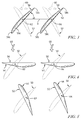
Figs. 3-5 are diagrammatic views of a pair of fan blades included in the fan ofFig. 2 moving from forward pitch angles through flat pitch angles to reverse pitch angles; and -
Fig. 6 is a diagrammatic view of a portion of a fan included in another embodiment of a gas turbine engine. - For the purposes of promoting an understanding of the principles of the disclosure, reference will now be made to a number of illustrative embodiments illustrated in the drawings and specific language will be used to describe the same.
- Referring now to
Fig. 1 , an illustrative aerospacegas turbine engine 10 is cut-away to show that theengine 10 includes afan 12 and anengine core 14 adapted to drive thefan 12. Thefan 12 and theengine core 14 are adapted to push air to propel an aircraft. Theengine core 14 includes acompressor 16, acombustor 18, and aturbine 20. Thecompressor 16 compresses and delivers air to thecombustor 18. Thecombustor 18 mixes the compressed air with fuel, ignites the air/fuel mixture, and delivers the combustion products (i.e., hot, high-pressure gases) to theturbine 20. Theturbine 20 converts the combustion products to mechanical energy (i.e., rotational power) that drives thecompressor 16 and thefan 12. Thefan 12, thecompressor 16, thecombustor 18, and theturbine 20 are illustratively arranged along acentral axis 22 of thegas turbine engine 10. - The
engine 10 further illustratively includes atransmission 24 that is arranged along thecentral axis 22 as shown inFig. 1 . Thetransmission 24 is coupled to theturbine 20 and thefan 12. Thetransmission 24 is configured to transmit rotational power generated by theturbine 20 about theaxis 22 to thefan 12. As a result, thefan 12 is driven by theturbine 20 through thetransmission 24 to rotate at a fan speed offset from a turbine speed of theturbine 20. In the illustrative embodiment, the fan speed of thefan 12 is illustratively less than the turbine speed of theturbine 20. - Referring now to
Fig. 2 , thefan 12 illustratively includes afan disk 28,fan blades 30, and guidevanes fan blades 30 along theaxis 22. Thefan disk 28 is adapted for rotation about thecentral axis 22. Thefan blades 30 are coupled to thefan disk 28 for common rotation with thefan disk 28 about theaxis 22. The guide vanes 32, 33 are coupled to astationary case 34 that extends around thefan blades 30 and are therefore constrained against rotation about theaxis 22. - The
fan blades 30 illustratively include first-stage fan blades 36 and and second-stage fan blades 38 spaced axially aft of the first-stage fan blades 36 along theaxis 22 as shown inFig. 2 . Thefan blades axis 22 without a stationary component positioned between theblades axis 22. In the illustrative embodiment, thefan blades blades blades - The first and second-
stage fan blades fan disk 28 for movement relative to thefan disk 28 from forward pitch angles 50 to reverse pitch angles 52 (best seen inFigs. 3 and 5 ). The forward pitch angles 50 are associated with air directed aftward by theblades 30 along theaxis 22, whereas the reverse pitch angles 52 are associated with air directed forward by theblades 30 along theaxis 22. The forward pitch angles 50 and the reverse pitch angles 52 are therefore associated with forward and reverse thrust, respectively. In the illustrative embodiment, each of the first and second-stage fan blades - The
fan 12 further illustratively includes apitch adjustment mechanism 40 as shown inFig. 2 . Thepitch adjustment mechanism 40 is adapted to move either the first-stage fan blades 36 or the second-stage fan blades 38 relative to thefan disk 28 from the forward pitch angles 50 to the reverse pitch angles 52. Thepitch adjustment mechanism 40 may be embodied as, or otherwise include, one or more hydraulic, electric, or pneumatic actuators. Under the control of a controller included in theengine 10, thepitch adjustment mechanism 40 may be operable to move either the first-stage fan blades 36 or the second-stage fan blades 38 as indicated above. In the illustrative embodiment, movement of one of the first and second-stage fan blades mechanism 40 causes movement of the other of the first and second-stage fan blades - The
fan 12 further illustratively includes a torque-transmittingmechanism 42 as shown inFig. 2 . The torque-transmittingmechanism 42 is coupled between the first and second-stage fan blades stage fan blades stage fan blades blades mechanism 40 causes movement of the other of thefan blades mechanism 42. - The torque-transmitting
mechanism 42 is illustratively embodied as an idler gear as shown inFig. 2 . Theidler gear 42 is coupled between the first-stage fan blades 36 and the second-stage fan blades 38 to transmit rotation between theblades idler gear 42 couples theblades blades fan disk 28 from the forward pitch angles 50 to the reverse pitch angles 52 at substantially the same time. - In other embodiments, the torque-transmitting
mechanism 42 may embodied as, or otherwise include, one or more mechanisms adapted to transmit rotation between theblades mechanism 42 may be embodied as, or otherwise include, a toothed belt drive. In other examples, the torque-transmittingmechanism 42 may be embodied as, or otherwise include, a chain drive, a linkage, or the like. - The illustrative arrangement of the blades 30 (i.e., the stages of
blades fan 12 to have a lower hub-to-tip ratio than a fan having one variable pitch blade stage. For the fan having one variable pitch blade stage, a single ring of circumferentially adjacent bearings carried by the one-blade-stage fan disk are used to support the one blade stage for movement relative to the one-blade-stage fan disk. Thus, the overall bearing loads associated with the fan having one variable pitch blade stage are borne by a single ring of bearings. In contrast, for thefan 12, two rings of circumferentially adjacent bearings are used to support theblades fan disk 28. The overall bearing loads associated with thefan 12 are therefore borne by two rings of bearings, causing each ring of bearings of thefan 12 to experience a smaller load than the loads borne by the single ring of bearings of the fan having one variable pitch blade stage. To handle the larger loads, the bearings of the fan having one variable pitch blade stage may have larger diameters than the bearings of thefan 12. As a result, to minimize circumferential interference between the larger diameter bearings of the fan having one variable pitch blade stage, the diameter of the one-blade-stage fan disk may be greater than the diameter of thefan disk 28. Consequently, thefan 12 may have a lower hub-to-tip ratio than the hub-to-tip ratio of the one-blade-stage fan. Thefan 12 illustratively has a hub-to-tip ratio within the range of about 0.20 to 0.28. - In operation, for a given loading level, the
fan 12 may provide a higher pressure ratio than the pressure ratio provided by the one-blade-stage fan. As a result, for that loading level, thefan 12 may have an operating efficiency that is more desirable than the operating efficiency of the one-blade-stage fan. - Referring now to
Figs. 3-5 , in operation of thefan 12, thefan blades 30 move relative to thefan disk 28 from the forward pitch angles 50 associated with forward thrust to the reverse pitch angles 52 associated with reverse thrust. Specifically, circumferentiallyadjacent fan blades fan blades 30 move from the forward pitch angles 50 (shown inFig. 3 ) through flat pitch angles 54 (shown inFig. 4 ) associated with a lack of air being directed aftward along theaxis 22 by theblades 30 to the reverse pitch angles 52 (shown inFig. 5 ). - As shown in
Figs. 3-5 , thefan blades angles 50 through theangles 54 to theangles 52 in the counterclockwise direction indicated byarrow 60. The counterclockwise direction indicated by thearrow 60 may be said to be a direction of decreasing incidence. Additionally, the illustrative movement of theblades blades angles 50 through theangles 54 to theangles 52, or transitioning from theangles 50 to theangles 52 through fine. In the illustrative embodiment, the transition of theblades angles 50 through theangles 54 to theangles 52 in the direction indicated byarrow 60 may be associated with some degree of unsteadiness. - In other embodiments, the
fan blades angles 50 through theangles 54 to theangles 52 in the clockwise direction. The clockwise direction may be said to be a direction of increasing incidence. Additionally, movement of theblades blades angles 50 through theangles 54 to theangles 52, or transitioning from theangles 50 to theangles 52 through coarse. The transition of theblades angles 50 through theangles 54 to theangles 52 in the clockwise direction may be associated with a greater degree of unsteadiness than that associated with the transition from theangles 50 through theangles 54 to theangles 52 in the counterclockwise direction indicated byarrow 60. - Referring now to
Fig. 3 , forward pitch angles 50 of the circumferentiallyadjacent fan blades blades stage fan blades blades blades Fig. 3 . Theblades arrow 60 aboutrespective axes axis 22. - As indicated above, the
blades blade 56 has achord length 56c that extends from a trailingedge 56t to a leading edge 56l of theblade 56 as shown inFig. 3 . Theblade 58 has achord length 58c that extends from a trailingedge 58t to a leading edge 58l of theblade 58 as shown inFig. 3 . Thechord lengths respective blades chord lengths blades axes Fig. 3 . In the illustrative embodiment, the ratio of each of thechord lengths blades - Referring now to
Fig. 4 , flat pitch angles 54 of thefan blades blades blades Fig. 4 . The flat pitch angles 54 are associated with a lack of air being directed aftward along theaxis 22 by theblades - Because the
blades blades arrow 60 in a spaced-apart relationship with one another as shown inFig. 4 . Moreover, the solidity of theblades blades - Referring now to
Fig. 5 , reverse pitch angles 52 of thefan blades blades blades Fig. 5 . Once theblades fan 12 produces reverse thrust to brake the aircraft carrying theengine 10. - Referring now to
Fig. 6 , anotherfan 112 adapted for use in agas turbine engine 110 is shown. Thegas turbine 110 is substantially similar to thegas turbine engine 10 shown inFig. 1 and described herein. Thefan 112 of theengine 110 differs from thefan 12 of theengine 10, as described in more detail below. - The
fan 112 illustratively includes afan disk 128,fan blades 130, and guidevanes fan blades 130 along acentral axis 122 of theengine 110 as shown inFig. 6 . Thefan disk 128 is adapted for rotation about theaxis 122. Thefan blades 130 are coupled to thefan disk 128 for common rotation with thefan disk 128 about theaxis 122. The guide vanes 132, 133 are coupled to astationary case 134 that extends around thefan blades 130 and are therefore constrained against rotation about theaxis 122. - In the illustrative embodiment, the
stationary case 134 extends aftward and inward toward theaxis 122 in the radial direction, i.e., the direction perpendicular to theaxis 122 as shown inFig. 6 . Thefan disk 128 extends aftward and outward away from theaxis 122 in the radial direction. Thecase 134 and thefan disk 128 cooperate to define aflow path 162 therebetween. Theflow path 162 illustratively has an area A1 adjacent thefan blades 130 and an area A2 adjacent theoutlet guide vanes 132 that is less than the area A1. As such, theflow path 162 is contracted in the axial direction, i.e., the direction parallel to theaxis 122. In other embodiments, thestationary case 134 and thefan disk 128 may extend aftward in the axial direction substantially parallel to one another, like thecase 34 and thefan disk 28 of thefan 12. In such embodiments, theflow path 162 may not be contracted in the axial direction. - The
fan blades 130 illustratively include first-stage fan blades 136, second-stage fan blades 138, third-stage fan blades 164, and fourth-stage fan blades 166 as shown inFig. 6 . The second-stage fan blades 138 are spaced axially aft of the first-stage fan blades 136 along theaxis 122. The third-stage fan blades 164 are spaced axially aft of the second-stage fan blades 138 along theaxis 122. The fourth-stage fan blades 166 are spaced axially aft of the third-stage fan blades 164 along theaxis 122. Thefan blades axis 122 without a stationary component positioned between theblades axis 122. - The first, second, third, and fourth-
stage fan blades fan disk 128 for movement relative to thefan disk 128 from forward pitch angles through flat pitch angles to reverse pitch angles as suggested byFig. 6 . The forward pitch angles, the flat pitch angles, and the reverse pitch angles are substantially identically to the forward pitch, flat pitch, and reverse pitch angles 50, 54, 52 shown inFigs. 3-5 and described herein. In the illustrative embodiment, each of the first, second, third, and fourth-stage fan blades - The
fan 112 further illustratively includes apitch adjustment mechanism 140 as shown inFig. 6 . Thepitch adjustment mechanism 140 is adapted to move one of the first, second, third, and fourth-stage fan blades fan disk 128 from the forward pitch angles through the flat pitch angles to the reverse pitch angles. Thepitch adjustment mechanism 140 may be embodied as, or otherwise include, one or more hydraulic, electric, or pneumatic actuators. Under the control of a controller included in theengine 110, thepitch adjustment mechanism 140 may be operable to move one of theblades blades mechanism 140 causes movement of the other of theblades - The
fan 112 further includes a number of torque-transmittingmechanisms 142 as shown inFig. 6 . The torque-transmittingmechanisms 142 are coupled between the first, second, third, and fourth-stage fan blades blades blades blades mechanism 140 causes movement of the other of theblades mechanisms 142. - The torque-transmitting
mechanisms 142 are illustratively embodied as idler gears as shown inFig. 6 . The idler gears 142 are coupled between the first, second, third, and fourth-stage fan blades blades blades blades fan disk 128 from the forward pitch angles through the flat pitch angles to the reverse pitch angles at substantially the same time. - In other embodiments, the torque-transmitting
mechanisms 142 may be embodied as, or otherwise include, one or more mechanisms adapted to transmit rotation between theblades mechanisms 142 may include one or more toothed belt drives. In other examples, the torque-transmittingmechanisms 142 may include one or more chain drives, linkages, or the like. - The illustrative arrangement of the blades 130 (i.e., the stages of
blades fan 112 to have a lower hub-to-tip ratio than a fan having one blade stage, in substantially identical fashion to the arrangement of theblades 30 of thefan 12. Thefan 112 illustratively has a hub-to-tip ratio within the range of about 0.20 to 0.28. - In operation, for a given loading level, the
fan 112 may provide a higher pressure ratio than the pressure ratio provided by the one-blade-stage fan. As a result, for that loading level, thefan 112 may have an operating efficiency that is more desirable than the operating efficiency of the one-blade-stage fan. - Circumferentially adjacent blades of the first, second, third, and fourth-
stage fan blades blades Figs. 3-5 and described herein. Because theblades stage fan blades blades Fig. 4 . Additionally, the solidity of theblades blades blades Figs. 3-5 . - Referring now to
Figs. 1-6 , a method of operating an aircraft will be described. The method includes operating thefan engine fan disk - In the method described above, the plurality of fan blades include the stages of
blades - The present disclosure teaches a stacked variable pitch fan that has multiple variable pitch stages adjacent to each other without a stator positioned between the stages. The solidity of the blades of each stage is less than 1.0. The number of stages with solidity less than 1.0 is determined by the pressure ratio desired.
- One advantage of the stacked variable pitch fan is that the solidity of less than 1.0 for each variable pitch stage allows each stage to rotate to reverse pitch for reverse thrust by closing the fan blades. This feature provides an alternative to heavy cascade style thrust reversers or clamshell type thrust reversers. Achieving reverse thrust by closing the fan blades avoids the high forward thrust associated with achieving reverse thrust by opening the fan blades which is typically done when the blades each have solidity greater than 1.0. Achieving reverse thrust by closing the fan blades allows for a shorter runway distance than achieving reverse thrust by opening the fan blades.
- Another advantage of the stacked variable pitch fan is that the stacked variable pitch fan can provide a higher pressure ratio than the single stage fan. The pressure ratio, and therefore the operating efficiency, provided by a single stage fan having overall solidity of less than 1.0 is typically less than the pressure ratio and operating efficiency that is provided by a single stage fan having overall solidity of greater than or equal to 1.0. However, because the effective (i.e., the combined) solidity of the stacked variable pitch fan is greater than that of a single stage fan having an overall solidity of less than 1.0, the stacked variable pitch can provide a higher pressure ratio, and therefore a more desirable operating efficiency, than the pressure ratio and operating efficiency provided by the single stage fan having an overall solidity of less than 1.0.
- Yet another advantage of the stacked variable pitch fan is that the multiple stages of the stacked fan allow the hub-to-tip ratio of the fan to be reduced. Specifically, the multiple blade stages allow for more circumferential distance between the bearings that hold the spindles of the blades of each of the stages.
- There are several ways the stacked variable pitch fan could be implemented depending on the cycle requirements of the fan. For very low pressure ratio fans, a two-stage fan with no contraction in the flowpath could be used. However, with contraction in the flowpath, a higher pressure ratio could be generated. For higher pressure ratio fans, three or four stages of blades with an optionally contracting fan annulus could be used to generate the pressure ratio while still allowing for each stage to have solidity of less than 1.0.
- For both the two-stage and four-stage variable pitch fans, a variable pitch actuator may be used to control only one of the stages. An idler gear may be positioned between the stages of the two-stage and four-stage variable pitch fan so that the other stage(s) of the two and four-stage fans are controlled in response to the control of the only one stage.
- While the disclosure has been illustrated and described in detail in the foregoing drawings and description, the same is to be considered as exemplary and not restrictive in character, it being understood that only illustrative embodiments thereof have been shown and described and that all changes and modifications that come within the spirit of the disclosure are desired to be protected.
Claims (15)
- A fan (12, 112) for a gas turbine engine, the fan (12, 112) comprising
a fan disk (28, 128) adapted for rotation about a central axis (22), and
a plurality of fan blades (36, 38, 56, 58, 130, 136, 138, 164, 166) coupled to the fan disk (28, 128) for rotation therewith about the central axis (22), the plurality of fan blades (36, 38, 56, 58, 130, 136, 138, 164, 166) including first-stage fan blades (36, 136) and second-stage fan blades (38, 138) spaced axially aft of the first-stage fan blades (36, 136) along the central axis (22),
wherein the first-stage and second-stage fan blades (36, 38, 136, 138) are coupled to the fan disk (28, 128) for movement relative to the fan disk (28, 128) from forward pitch angles (50) associated with air directed aftward along the central axis (22) to reverse pitch angles (52) associated with air directed forward along the central axis (22), and each of the first-stage and second-stage fan blades (26, 38, 136, 138) have preferably a solidity of less than 1.0. - The fan (12, 112) of claim 1, wherein the first-stage and second-stage fan blades (36, 38, 136, 138) are coupled together for movement relative to the fan disk (28, 128) from the forward pitch angles (50) to the reverse pitch angles (52) at substantially the same time.
- The fan (12, 112) of claim 2, further comprising an idler gear (42, 142) coupled between the first-stage and second-stage fan blades (36, 38, 136, 138), the idler gear (42, 142) coupling the first-stage and second-stage fan blades (36, 38, 136, 138) to cause movement of the first-stage and second-stage fan blades (36, 38, 136, 138) relative to the fan disk (28, 128) preferably from the forward pitch angles (50) through flat pitch angles (54) to the reverse pitch angles (52) at substantially the same time.
- The fan (12, 112) of one of the preceding claims wherein the first-stage and second-stage fan blades (36, 38, 136, 138) are coupled to the fan disk (28, 128) for movement relative to the fan disk (28, 128) from the forward pitch angles (50) to the reverse pitch angles (52) in a counterclockwise direction.
- The fan (12, 112) of claim 4, wherein the fan (12, 112) has a hub-to-tip ratio within the range of about 0.20 to 0.28.
- The fan (12, 112) of one of the preceding claims wherein the plurality of fan blades (36, 38, 56, 58, 130, 136, 138, 164, 166) includes (i) third-stage fan blades (164) spaced axially aft of the second-stage fan blades (38, 138) along the central axis (22) and (ii) fourth-stage fan blades (166) spaced axially aft of the third-stage fan blades (164) along the central axis (22), the third-stage and fourth-stage fan blades (164, 166) are coupled to the fan disk (28, 128) for movement relative to the fan disk (28, 128) from forward pitch angles (50) associated with air directed aftward along the central axis (22) to reverse pitch angles (52) associated with air directed forward along the central axis (22), and each of the third-stage and fourth-stage fan blades (164, 166) have a solidity of less than 1.0.
- The fan (12, 112) of claim 6, wherein the third-stage and fourth-stage fan blades (164, 166) are coupled together for movement relative to the fan disk (28, 128) from the forward pitch angles (50) to the reverse pitch angles (52) at substantially the same time.
- The fan (12, 112) of claim 7, further comprising an idler gear (42, 142) coupled between the third-stage and fourth-stage fan blades (164, 166), the idler gear (42, 142) coupling the third-stage and fourth-stage fan blades (164, 166) to cause movement of the third-stage and fourth-stage fan blades (164, 166) relative to the fan disk (28, 128) at substantially the same time.
- The fan (12, 112) of claim 6, wherein the first-stage, second-stage, third-stage, and fourth-stage fan blades (166) are coupled to the fan disk (28, 128) for movement relative to the fan disk (28, 128) from the forward pitch angles (50) to the reverse pitch angles (52) in a counterclockwise direction.
- The fan (12, 112) of claim 9, wherein the fan (12, 112) has a hub-to-tip ratio within the range of about 0.20 to 0.28.
- The fan (12, 112) of one of the preceding claims wherein circumferentially adjacent blades of the first-stage fan blades (36, 136) are movable past one another in a spaced-apart relationship with one another when the first-stage fan blades (36, 136) are moved relative to the fan disk (28, 128) from the forward pitch angles (50) to the reverse pitch angles (52), and circumferentially adjacent blades of the second-stage fan blades (38, 138) are movable past one another in a spaced-apart relationship with one another when the second-stage fan blades (38, 138) are moved relative to the fan disk (28, 128) from the forward pitch angles (50) to the reverse pitch angles (52).
- The fan (12, 112) of claim 11, wherein the plurality of fan blades (36, 38, 56, 58, 130, 136, 138, 164, 166) includes (i) third-stage fan blades (164) spaced axially aft of the second-stage fan blades (38, 138) along the central axis (22) and (ii) fourth-stage fan blades (166) spaced axially aft of the third-stage fan blades (164) along the central axis (22), the third-stage and fourth-stage fan blades (164, 166) are coupled to the fan disk (28, 128) for movement relative to the fan disk (28, 128) from forward pitch angles (50) associated with air directed aftward along the central axis (22) to reverse pitch angles (52) associated with air directed forward along the central axis (22), circumferentially adjacent blades of the third-stage fan blades (164) are movable past one another in a spaced-apart relationship with one another when the third-stage fan blades (164) are moved relative to the fan disk (28, 128) from the forward pitch angles (50) to the reverse pitch angles (52), and circumferentially adjacent blades of the fourth-stage fan blades (166) are movable past one another in a spaced-apart relationship with one another when the fourth-stage fan blades (166) are moved relative to the fan disk (28, 128) from the forward pitch angles (50) to the reverse pitch angles (52).
- A fan (12, 112) of one of the preceding claims
wherein the first-stage and second-stage fan blades (36, 38, 136, 138) are coupled to the fan disk (28, 128) for movement relative to the fan disk (28, 128) from forward pitch angles (50) associated with air directed aftward along the central axis (22) through flat pitch angles (54) associated with a lack of air being directed aftward along the central axis (22) to reverse pitch angles (52) associated with air directed forward along the central axis (22). - The fan (12, 112) of claim 13, wherein circumferentially adjacent blades of the first-stage fan blades (36, 136) are in a spaced-apart relationship with one another when the first-stage fan blades (36, 136) move through the flat pitch angles (54) and circumferentially adjacent blades of the second-stage fan blades (38, 138) are in a spaced-apart relationship with one another when the second-stage fan blades (38, 138) move through the flat pitch angles (54),and
wherein the plurality of fan blades (36, 38, 56, 58, 130, 136, 138, 164, 166) include (i) third-stage fan blades (164) spaced axially aft of the second-stage fan blades (38, 138) along the central axis (22) and (ii) fourth-stage fan blades (166) spaced axially aft of the third-stage fan blades (164) along the central axis (22), the third and fourth-stage fan blades (166) are coupled to the fan disk (28, 128) for movement relative to the fan disk (28, 128) from forward pitch angles (50) associated with air directed aftward along the central axis (22) through flat pitch angles (54) associated with a lack of air being directed aftward along the central axis (22) to reverse pitch angles (52) associated with air directed forward along the central axis (22), circumferentially adjacent blades of the third-stage fan blades (164) are in a spaced-apart relationship with one another when the third-stage fan blades (164) move through the flat pitch angles (54), and circumferentially adjacent blades of the fourth-stage fan blades (166) are in a spaced-apart relationship with one another when the fourth-stage fan blades (166) move through the flat pitch angles (54). - A method of operating an aircraft, the method comprising
operating a fan (12, 112) included in a gas turbine engine of the aircraft so that a plurality of fan blades (36, 38, 56, 58, 130, 136, 138, 164, 166) of the fan (12, 112) have forward pitch angles (50) associated with air directed aftward along a central axis (22) of the gas turbine engine, and
moving the plurality of fan blades (36, 38, 56, 58, 130, 136, 138, 164, 166) relative to a fan disk (28, 128) of the fan (12, 112) from the forward pitch angles (50) through flat pitch angles (54) associated with a lack of air being directed aftward along the central axis (22) toward reverse pitch angles (52) associated with air directed forward along the central axis (22).
Applications Claiming Priority (1)
| Application Number | Priority Date | Filing Date | Title |
|---|---|---|---|
| US201562132148P | 2015-03-12 | 2015-03-12 |
Publications (2)
| Publication Number | Publication Date |
|---|---|
| EP3067566A1 true EP3067566A1 (en) | 2016-09-14 |
| EP3067566B1 EP3067566B1 (en) | 2018-08-22 |
Family
ID=55486569
Family Applications (1)
| Application Number | Title | Priority Date | Filing Date |
|---|---|---|---|
| EP16159059.1A Active EP3067566B1 (en) | 2015-03-12 | 2016-03-08 | Multi-stage co-rotating variable pitch fan |
Country Status (2)
| Country | Link |
|---|---|
| US (1) | US10253784B2 (en) |
| EP (1) | EP3067566B1 (en) |
Cited By (3)
| Publication number | Priority date | Publication date | Assignee | Title |
|---|---|---|---|---|
| EP3828384A1 (en) * | 2019-11-26 | 2021-06-02 | Rolls-Royce plc | Gas turbine engine |
| EP4043713A1 (en) * | 2021-02-15 | 2022-08-17 | General Electric Company | Variable pitch fans for turbomachinery engines |
| EP4321746A1 (en) * | 2022-08-12 | 2024-02-14 | General Electric Company | Variable pitch fans for turbomachinery engines |
Families Citing this family (10)
| Publication number | Priority date | Publication date | Assignee | Title |
|---|---|---|---|---|
| US9303589B2 (en) | 2012-11-28 | 2016-04-05 | Pratt & Whitney Canada Corp. | Low hub-to-tip ratio fan for a turbofan gas turbine engine |
| US10830066B2 (en) * | 2016-01-05 | 2020-11-10 | Safran Aircraft Engines | Low-pitch variable-setting fan of a turbine engine |
| GB201702383D0 (en) * | 2017-02-14 | 2017-03-29 | Rolls Royce Plc | Gas turbine engine fan blade with axial lean |
| US11203423B2 (en) * | 2017-06-01 | 2021-12-21 | Karem Aircraft, Inc. | Use of individual blade control on a propeller or rotor in axial flight for the purpose of aerodynamic braking and power response modulation |
| US10473111B2 (en) * | 2017-10-18 | 2019-11-12 | Rolls-Royce Corporation | Variable pitch fan for a gas turbine engine |
| DE102018212176A1 (en) * | 2018-07-23 | 2020-01-23 | MTU Aero Engines AG | High pressure compressor for an engine |
| US11814154B2 (en) * | 2020-08-31 | 2023-11-14 | General Electric Company | Pitch angles of an aircraft engine rotor assembly |
| US11946437B2 (en) | 2021-02-15 | 2024-04-02 | General Electric Company | Variable pitch fans for turbomachinery engines |
| US12060812B1 (en) * | 2023-03-16 | 2024-08-13 | General Electric Company | Turbo engine having blade pitch actuation system for variable pitch fan |
| US12326114B2 (en) * | 2023-08-15 | 2025-06-10 | Rtx Corporation | Gas turbine engine with core debris protection |
Citations (2)
| Publication number | Priority date | Publication date | Assignee | Title |
|---|---|---|---|---|
| CH244980A (en) * | 1945-02-22 | 1946-10-15 | Escher Wyss Maschf Ag | Recoil drive for vehicles, in particular aircraft. |
| US3946554A (en) * | 1974-09-06 | 1976-03-30 | General Electric Company | Variable pitch turbofan engine and a method for operating same |
Family Cites Families (13)
| Publication number | Priority date | Publication date | Assignee | Title |
|---|---|---|---|---|
| DE866145C (en) * | 1944-07-21 | 1953-02-09 | Daimler Benz Ag | Method and device for starting two-circuit jet engines, in particular for aircraft |
| GB819032A (en) * | 1955-09-30 | 1959-08-26 | Power Jets Res & Dev Ltd | Improvements in or relating to jet propulsion engines |
| DE1626028C3 (en) * | 1966-04-12 | 1974-04-04 | Dowty Rotol Ltd., Gloucester (Grossbritannien) | By-pass gas turbine engine |
| US4657484A (en) | 1984-09-04 | 1987-04-14 | General Electric Company | Blade pitch varying means |
| US4664599A (en) | 1985-05-01 | 1987-05-12 | United Technologies Corporation | Two stage turbine rotor assembly |
| US4860537A (en) | 1986-08-29 | 1989-08-29 | Brandt, Inc. | High bypass ratio counterrotating gearless front fan engine |
| GB2195712B (en) | 1986-10-08 | 1990-08-29 | Rolls Royce Plc | A turbofan gas turbine engine |
| US4976102A (en) | 1988-05-09 | 1990-12-11 | General Electric Company | Unducted, counterrotating gearless front fan engine |
| US4936748A (en) | 1988-11-28 | 1990-06-26 | General Electric Company | Auxiliary power source in an unducted fan gas turbine engine |
| DE4122008A1 (en) * | 1991-07-03 | 1993-01-14 | Mtu Muenchen Gmbh | GAUGE ENGINE WITH COUNTER-PRESSURE LOW-PRESSURE COMPRESSOR (BOOSTER) |
| USH2032H1 (en) | 1999-10-01 | 2002-07-02 | The United States Of America As Represented By The Secretary Of The Air Force | Integrated fan-core twin spool counter-rotating turbofan gas turbine engine |
| US8590286B2 (en) | 2007-12-05 | 2013-11-26 | United Technologies Corp. | Gas turbine engine systems involving tip fans |
| US10190496B2 (en) * | 2013-03-15 | 2019-01-29 | United Technologies Corporation | Turbofan engine bearing and gearbox arrangement |
-
2016
- 2016-03-08 EP EP16159059.1A patent/EP3067566B1/en active Active
- 2016-03-09 US US15/065,247 patent/US10253784B2/en active Active
Patent Citations (2)
| Publication number | Priority date | Publication date | Assignee | Title |
|---|---|---|---|---|
| CH244980A (en) * | 1945-02-22 | 1946-10-15 | Escher Wyss Maschf Ag | Recoil drive for vehicles, in particular aircraft. |
| US3946554A (en) * | 1974-09-06 | 1976-03-30 | General Electric Company | Variable pitch turbofan engine and a method for operating same |
Cited By (4)
| Publication number | Priority date | Publication date | Assignee | Title |
|---|---|---|---|---|
| EP3828384A1 (en) * | 2019-11-26 | 2021-06-02 | Rolls-Royce plc | Gas turbine engine |
| US11339727B2 (en) | 2019-11-26 | 2022-05-24 | Rolls-Royce Plc | Gas turbine engine |
| EP4043713A1 (en) * | 2021-02-15 | 2022-08-17 | General Electric Company | Variable pitch fans for turbomachinery engines |
| EP4321746A1 (en) * | 2022-08-12 | 2024-02-14 | General Electric Company | Variable pitch fans for turbomachinery engines |
Also Published As
| Publication number | Publication date |
|---|---|
| EP3067566B1 (en) | 2018-08-22 |
| US10253784B2 (en) | 2019-04-09 |
| US20160265547A1 (en) | 2016-09-15 |
Similar Documents
| Publication | Publication Date | Title |
|---|---|---|
| US10253784B2 (en) | Multi-stage co-rotating variable pitch fan | |
| US10288083B2 (en) | Pitch range for a variable pitch fan | |
| EP1746258B1 (en) | Rack and pinion variable van synchronizing mechanism for inner diameter vane shroud | |
| EP2522814B1 (en) | Gear train variable vane synchronizing mechanism for inner diameter vane shroud | |
| EP2971599B1 (en) | Variable vane drive system | |
| US20140314549A1 (en) | Flow manipulating arrangement for a turbine exhaust diffuser | |
| US20130160454A1 (en) | Gas turbine engine with supersonic compressor | |
| EP3135922B1 (en) | Aircraft engine variable pitch fan pitch range limiter | |
| EP2123884A2 (en) | Dual clutch arrangement | |
| US8905887B2 (en) | Unison ring gear assembly | |
| US10794272B2 (en) | Axial and centrifugal compressor | |
| US20140064912A1 (en) | Systems and Methods to Control Variable Stator Vanes in Gas Turbine Engines | |
| US10677159B2 (en) | Gas turbine engine including a dual-speed split compressor | |
| US20200080432A1 (en) | Variable bypass ratio fan with variable pitch aft stage rotor blading | |
| US10428679B2 (en) | Aero-actuated vanes | |
| EP2703606A1 (en) | System and method to control variable stator vanes in gas turbine engines | |
| US20140064910A1 (en) | Systems and Methods to Control Variable Stator Vanes in Gas Turbine Engines | |
| US20190277154A1 (en) | Variable vane actuation arrangement | |
| EP3800366A1 (en) | Bearing spring for epicyclical gear system housing assembly | |
| US20140205424A1 (en) | Systems and Methods to Control Variable Stator Vanes in Gas Turbine Engines |
Legal Events
| Date | Code | Title | Description |
|---|---|---|---|
| PUAI | Public reference made under article 153(3) epc to a published international application that has entered the european phase |
Free format text: ORIGINAL CODE: 0009012 |
|
| AK | Designated contracting states |
Kind code of ref document: A1 Designated state(s): AL AT BE BG CH CY CZ DE DK EE ES FI FR GB GR HR HU IE IS IT LI LT LU LV MC MK MT NL NO PL PT RO RS SE SI SK SM TR |
|
| AX | Request for extension of the european patent |
Extension state: BA ME |
|
| STAA | Information on the status of an ep patent application or granted ep patent |
Free format text: STATUS: REQUEST FOR EXAMINATION WAS MADE |
|
| 17P | Request for examination filed |
Effective date: 20170224 |
|
| RBV | Designated contracting states (corrected) |
Designated state(s): AL AT BE BG CH CY CZ DE DK EE ES FI FR GB GR HR HU IE IS IT LI LT LU LV MC MK MT NL NO PL PT RO RS SE SI SK SM TR |
|
| GRAP | Despatch of communication of intention to grant a patent |
Free format text: ORIGINAL CODE: EPIDOSNIGR1 |
|
| STAA | Information on the status of an ep patent application or granted ep patent |
Free format text: STATUS: GRANT OF PATENT IS INTENDED |
|
| INTG | Intention to grant announced |
Effective date: 20180328 |
|
| GRAS | Grant fee paid |
Free format text: ORIGINAL CODE: EPIDOSNIGR3 |
|
| GRAA | (expected) grant |
Free format text: ORIGINAL CODE: 0009210 |
|
| STAA | Information on the status of an ep patent application or granted ep patent |
Free format text: STATUS: THE PATENT HAS BEEN GRANTED |
|
| AK | Designated contracting states |
Kind code of ref document: B1 Designated state(s): AL AT BE BG CH CY CZ DE DK EE ES FI FR GB GR HR HU IE IS IT LI LT LU LV MC MK MT NL NO PL PT RO RS SE SI SK SM TR |
|
| REG | Reference to a national code |
Ref country code: GB Ref legal event code: FG4D |
|
| REG | Reference to a national code |
Ref country code: CH Ref legal event code: EP |
|
| REG | Reference to a national code |
Ref country code: AT Ref legal event code: REF Ref document number: 1032852 Country of ref document: AT Kind code of ref document: T Effective date: 20180915 |
|
| REG | Reference to a national code |
Ref country code: IE Ref legal event code: FG4D |
|
| REG | Reference to a national code |
Ref country code: DE Ref legal event code: R096 Ref document number: 602016004877 Country of ref document: DE |
|
| REG | Reference to a national code |
Ref country code: NL Ref legal event code: MP Effective date: 20180822 |
|
| REG | Reference to a national code |
Ref country code: LT Ref legal event code: MG4D |
|
| PG25 | Lapsed in a contracting state [announced via postgrant information from national office to epo] |
Ref country code: IS Free format text: LAPSE BECAUSE OF FAILURE TO SUBMIT A TRANSLATION OF THE DESCRIPTION OR TO PAY THE FEE WITHIN THE PRESCRIBED TIME-LIMIT Effective date: 20181222 Ref country code: SE Free format text: LAPSE BECAUSE OF FAILURE TO SUBMIT A TRANSLATION OF THE DESCRIPTION OR TO PAY THE FEE WITHIN THE PRESCRIBED TIME-LIMIT Effective date: 20180822 Ref country code: RS Free format text: LAPSE BECAUSE OF FAILURE TO SUBMIT A TRANSLATION OF THE DESCRIPTION OR TO PAY THE FEE WITHIN THE PRESCRIBED TIME-LIMIT Effective date: 20180822 Ref country code: GR Free format text: LAPSE BECAUSE OF FAILURE TO SUBMIT A TRANSLATION OF THE DESCRIPTION OR TO PAY THE FEE WITHIN THE PRESCRIBED TIME-LIMIT Effective date: 20181123 Ref country code: FI Free format text: LAPSE BECAUSE OF FAILURE TO SUBMIT A TRANSLATION OF THE DESCRIPTION OR TO PAY THE FEE WITHIN THE PRESCRIBED TIME-LIMIT Effective date: 20180822 Ref country code: NO Free format text: LAPSE BECAUSE OF FAILURE TO SUBMIT A TRANSLATION OF THE DESCRIPTION OR TO PAY THE FEE WITHIN THE PRESCRIBED TIME-LIMIT Effective date: 20181122 Ref country code: NL Free format text: LAPSE BECAUSE OF FAILURE TO SUBMIT A TRANSLATION OF THE DESCRIPTION OR TO PAY THE FEE WITHIN THE PRESCRIBED TIME-LIMIT Effective date: 20180822 Ref country code: BG Free format text: LAPSE BECAUSE OF FAILURE TO SUBMIT A TRANSLATION OF THE DESCRIPTION OR TO PAY THE FEE WITHIN THE PRESCRIBED TIME-LIMIT Effective date: 20181122 Ref country code: LT Free format text: LAPSE BECAUSE OF FAILURE TO SUBMIT A TRANSLATION OF THE DESCRIPTION OR TO PAY THE FEE WITHIN THE PRESCRIBED TIME-LIMIT Effective date: 20180822 |
|
| REG | Reference to a national code |
Ref country code: AT Ref legal event code: MK05 Ref document number: 1032852 Country of ref document: AT Kind code of ref document: T Effective date: 20180822 |
|
| PG25 | Lapsed in a contracting state [announced via postgrant information from national office to epo] |
Ref country code: HR Free format text: LAPSE BECAUSE OF FAILURE TO SUBMIT A TRANSLATION OF THE DESCRIPTION OR TO PAY THE FEE WITHIN THE PRESCRIBED TIME-LIMIT Effective date: 20180822 Ref country code: LV Free format text: LAPSE BECAUSE OF FAILURE TO SUBMIT A TRANSLATION OF THE DESCRIPTION OR TO PAY THE FEE WITHIN THE PRESCRIBED TIME-LIMIT Effective date: 20180822 Ref country code: AL Free format text: LAPSE BECAUSE OF FAILURE TO SUBMIT A TRANSLATION OF THE DESCRIPTION OR TO PAY THE FEE WITHIN THE PRESCRIBED TIME-LIMIT Effective date: 20180822 |
|
| PG25 | Lapsed in a contracting state [announced via postgrant information from national office to epo] |
Ref country code: CZ Free format text: LAPSE BECAUSE OF FAILURE TO SUBMIT A TRANSLATION OF THE DESCRIPTION OR TO PAY THE FEE WITHIN THE PRESCRIBED TIME-LIMIT Effective date: 20180822 Ref country code: RO Free format text: LAPSE BECAUSE OF FAILURE TO SUBMIT A TRANSLATION OF THE DESCRIPTION OR TO PAY THE FEE WITHIN THE PRESCRIBED TIME-LIMIT Effective date: 20180822 Ref country code: ES Free format text: LAPSE BECAUSE OF FAILURE TO SUBMIT A TRANSLATION OF THE DESCRIPTION OR TO PAY THE FEE WITHIN THE PRESCRIBED TIME-LIMIT Effective date: 20180822 Ref country code: EE Free format text: LAPSE BECAUSE OF FAILURE TO SUBMIT A TRANSLATION OF THE DESCRIPTION OR TO PAY THE FEE WITHIN THE PRESCRIBED TIME-LIMIT Effective date: 20180822 Ref country code: PL Free format text: LAPSE BECAUSE OF FAILURE TO SUBMIT A TRANSLATION OF THE DESCRIPTION OR TO PAY THE FEE WITHIN THE PRESCRIBED TIME-LIMIT Effective date: 20180822 Ref country code: AT Free format text: LAPSE BECAUSE OF FAILURE TO SUBMIT A TRANSLATION OF THE DESCRIPTION OR TO PAY THE FEE WITHIN THE PRESCRIBED TIME-LIMIT Effective date: 20180822 Ref country code: IT Free format text: LAPSE BECAUSE OF FAILURE TO SUBMIT A TRANSLATION OF THE DESCRIPTION OR TO PAY THE FEE WITHIN THE PRESCRIBED TIME-LIMIT Effective date: 20180822 |
|
| REG | Reference to a national code |
Ref country code: DE Ref legal event code: R097 Ref document number: 602016004877 Country of ref document: DE |
|
| PG25 | Lapsed in a contracting state [announced via postgrant information from national office to epo] |
Ref country code: SM Free format text: LAPSE BECAUSE OF FAILURE TO SUBMIT A TRANSLATION OF THE DESCRIPTION OR TO PAY THE FEE WITHIN THE PRESCRIBED TIME-LIMIT Effective date: 20180822 Ref country code: DK Free format text: LAPSE BECAUSE OF FAILURE TO SUBMIT A TRANSLATION OF THE DESCRIPTION OR TO PAY THE FEE WITHIN THE PRESCRIBED TIME-LIMIT Effective date: 20180822 Ref country code: SK Free format text: LAPSE BECAUSE OF FAILURE TO SUBMIT A TRANSLATION OF THE DESCRIPTION OR TO PAY THE FEE WITHIN THE PRESCRIBED TIME-LIMIT Effective date: 20180822 |
|
| PLBE | No opposition filed within time limit |
Free format text: ORIGINAL CODE: 0009261 |
|
| STAA | Information on the status of an ep patent application or granted ep patent |
Free format text: STATUS: NO OPPOSITION FILED WITHIN TIME LIMIT |
|
| 26N | No opposition filed |
Effective date: 20190523 |
|
| PG25 | Lapsed in a contracting state [announced via postgrant information from national office to epo] |
Ref country code: SI Free format text: LAPSE BECAUSE OF FAILURE TO SUBMIT A TRANSLATION OF THE DESCRIPTION OR TO PAY THE FEE WITHIN THE PRESCRIBED TIME-LIMIT Effective date: 20180822 |
|
| PG25 | Lapsed in a contracting state [announced via postgrant information from national office to epo] |
Ref country code: MC Free format text: LAPSE BECAUSE OF FAILURE TO SUBMIT A TRANSLATION OF THE DESCRIPTION OR TO PAY THE FEE WITHIN THE PRESCRIBED TIME-LIMIT Effective date: 20180822 |
|
| REG | Reference to a national code |
Ref country code: CH Ref legal event code: PL |
|
| PG25 | Lapsed in a contracting state [announced via postgrant information from national office to epo] |
Ref country code: LU Free format text: LAPSE BECAUSE OF NON-PAYMENT OF DUE FEES Effective date: 20190308 |
|
| REG | Reference to a national code |
Ref country code: BE Ref legal event code: MM Effective date: 20190331 |
|
| PG25 | Lapsed in a contracting state [announced via postgrant information from national office to epo] |
Ref country code: LI Free format text: LAPSE BECAUSE OF NON-PAYMENT OF DUE FEES Effective date: 20190331 Ref country code: IE Free format text: LAPSE BECAUSE OF NON-PAYMENT OF DUE FEES Effective date: 20190308 Ref country code: CH Free format text: LAPSE BECAUSE OF NON-PAYMENT OF DUE FEES Effective date: 20190331 |
|
| PG25 | Lapsed in a contracting state [announced via postgrant information from national office to epo] |
Ref country code: BE Free format text: LAPSE BECAUSE OF NON-PAYMENT OF DUE FEES Effective date: 20190331 |
|
| PG25 | Lapsed in a contracting state [announced via postgrant information from national office to epo] |
Ref country code: TR Free format text: LAPSE BECAUSE OF FAILURE TO SUBMIT A TRANSLATION OF THE DESCRIPTION OR TO PAY THE FEE WITHIN THE PRESCRIBED TIME-LIMIT Effective date: 20180822 |
|
| PG25 | Lapsed in a contracting state [announced via postgrant information from national office to epo] |
Ref country code: MT Free format text: LAPSE BECAUSE OF NON-PAYMENT OF DUE FEES Effective date: 20190308 Ref country code: PT Free format text: LAPSE BECAUSE OF FAILURE TO SUBMIT A TRANSLATION OF THE DESCRIPTION OR TO PAY THE FEE WITHIN THE PRESCRIBED TIME-LIMIT Effective date: 20181222 |
|
| GBPC | Gb: european patent ceased through non-payment of renewal fee |
Effective date: 20200308 |
|
| PG25 | Lapsed in a contracting state [announced via postgrant information from national office to epo] |
Ref country code: GB Free format text: LAPSE BECAUSE OF NON-PAYMENT OF DUE FEES Effective date: 20200308 |
|
| PG25 | Lapsed in a contracting state [announced via postgrant information from national office to epo] |
Ref country code: CY Free format text: LAPSE BECAUSE OF FAILURE TO SUBMIT A TRANSLATION OF THE DESCRIPTION OR TO PAY THE FEE WITHIN THE PRESCRIBED TIME-LIMIT Effective date: 20180822 |
|
| PG25 | Lapsed in a contracting state [announced via postgrant information from national office to epo] |
Ref country code: HU Free format text: LAPSE BECAUSE OF FAILURE TO SUBMIT A TRANSLATION OF THE DESCRIPTION OR TO PAY THE FEE WITHIN THE PRESCRIBED TIME-LIMIT; INVALID AB INITIO Effective date: 20160308 |
|
| PG25 | Lapsed in a contracting state [announced via postgrant information from national office to epo] |
Ref country code: MK Free format text: LAPSE BECAUSE OF FAILURE TO SUBMIT A TRANSLATION OF THE DESCRIPTION OR TO PAY THE FEE WITHIN THE PRESCRIBED TIME-LIMIT Effective date: 20180822 |
|
| P01 | Opt-out of the competence of the unified patent court (upc) registered |
Effective date: 20230528 |
|
| PGFP | Annual fee paid to national office [announced via postgrant information from national office to epo] |
Ref country code: DE Payment date: 20260320 Year of fee payment: 11 |
|
| PGFP | Annual fee paid to national office [announced via postgrant information from national office to epo] |
Ref country code: FR Payment date: 20260323 Year of fee payment: 11 |