EP3067556A1 - System and method for variable tip-speed-ratio control of a wind turbine - Google Patents
System and method for variable tip-speed-ratio control of a wind turbine Download PDFInfo
- Publication number
- EP3067556A1 EP3067556A1 EP16159952.7A EP16159952A EP3067556A1 EP 3067556 A1 EP3067556 A1 EP 3067556A1 EP 16159952 A EP16159952 A EP 16159952A EP 3067556 A1 EP3067556 A1 EP 3067556A1
- Authority
- EP
- European Patent Office
- Prior art keywords
- wind turbine
- torque
- speed
- tip
- set point
- Prior art date
- Legal status (The legal status is an assumption and is not a legal conclusion. Google has not performed a legal analysis and makes no representation as to the accuracy of the status listed.)
- Granted
Links
Images







Classifications
-
- F—MECHANICAL ENGINEERING; LIGHTING; HEATING; WEAPONS; BLASTING
- F03—MACHINES OR ENGINES FOR LIQUIDS; WIND, SPRING, OR WEIGHT MOTORS; PRODUCING MECHANICAL POWER OR A REACTIVE PROPULSIVE THRUST, NOT OTHERWISE PROVIDED FOR
- F03D—WIND MOTORS
- F03D7/00—Controlling wind motors
- F03D7/02—Controlling wind motors the wind motors having rotation axis substantially parallel to the air flow entering the rotor
- F03D7/022—Adjusting aerodynamic properties of the blades
- F03D7/0224—Adjusting blade pitch
-
- F—MECHANICAL ENGINEERING; LIGHTING; HEATING; WEAPONS; BLASTING
- F03—MACHINES OR ENGINES FOR LIQUIDS; WIND, SPRING, OR WEIGHT MOTORS; PRODUCING MECHANICAL POWER OR A REACTIVE PROPULSIVE THRUST, NOT OTHERWISE PROVIDED FOR
- F03D—WIND MOTORS
- F03D7/00—Controlling wind motors
- F03D7/02—Controlling wind motors the wind motors having rotation axis substantially parallel to the air flow entering the rotor
- F03D7/028—Controlling wind motors the wind motors having rotation axis substantially parallel to the air flow entering the rotor controlling wind motor output power
-
- F—MECHANICAL ENGINEERING; LIGHTING; HEATING; WEAPONS; BLASTING
- F03—MACHINES OR ENGINES FOR LIQUIDS; WIND, SPRING, OR WEIGHT MOTORS; PRODUCING MECHANICAL POWER OR A REACTIVE PROPULSIVE THRUST, NOT OTHERWISE PROVIDED FOR
- F03D—WIND MOTORS
- F03D1/00—Wind motors with rotation axis substantially parallel to the air flow entering the rotor
- F03D1/06—Rotors
-
- F—MECHANICAL ENGINEERING; LIGHTING; HEATING; WEAPONS; BLASTING
- F03—MACHINES OR ENGINES FOR LIQUIDS; WIND, SPRING, OR WEIGHT MOTORS; PRODUCING MECHANICAL POWER OR A REACTIVE PROPULSIVE THRUST, NOT OTHERWISE PROVIDED FOR
- F03D—WIND MOTORS
- F03D7/00—Controlling wind motors
- F03D7/02—Controlling wind motors the wind motors having rotation axis substantially parallel to the air flow entering the rotor
- F03D7/0276—Controlling wind motors the wind motors having rotation axis substantially parallel to the air flow entering the rotor controlling rotor speed, e.g. variable speed
-
- F—MECHANICAL ENGINEERING; LIGHTING; HEATING; WEAPONS; BLASTING
- F03—MACHINES OR ENGINES FOR LIQUIDS; WIND, SPRING, OR WEIGHT MOTORS; PRODUCING MECHANICAL POWER OR A REACTIVE PROPULSIVE THRUST, NOT OTHERWISE PROVIDED FOR
- F03D—WIND MOTORS
- F03D7/00—Controlling wind motors
- F03D7/02—Controlling wind motors the wind motors having rotation axis substantially parallel to the air flow entering the rotor
- F03D7/04—Automatic control; Regulation
- F03D7/042—Automatic control; Regulation by means of an electrical or electronic controller
-
- F—MECHANICAL ENGINEERING; LIGHTING; HEATING; WEAPONS; BLASTING
- F03—MACHINES OR ENGINES FOR LIQUIDS; WIND, SPRING, OR WEIGHT MOTORS; PRODUCING MECHANICAL POWER OR A REACTIVE PROPULSIVE THRUST, NOT OTHERWISE PROVIDED FOR
- F03D—WIND MOTORS
- F03D7/00—Controlling wind motors
- F03D7/02—Controlling wind motors the wind motors having rotation axis substantially parallel to the air flow entering the rotor
- F03D7/04—Automatic control; Regulation
- F03D7/042—Automatic control; Regulation by means of an electrical or electronic controller
- F03D7/047—Automatic control; Regulation by means of an electrical or electronic controller characterised by the controller architecture, e.g. multiple processors or data communications
-
- F—MECHANICAL ENGINEERING; LIGHTING; HEATING; WEAPONS; BLASTING
- F05—INDEXING SCHEMES RELATING TO ENGINES OR PUMPS IN VARIOUS SUBCLASSES OF CLASSES F01-F04
- F05B—INDEXING SCHEME RELATING TO WIND, SPRING, WEIGHT, INERTIA OR LIKE MOTORS, TO MACHINES OR ENGINES FOR LIQUIDS COVERED BY SUBCLASSES F03B, F03D AND F03G
- F05B2270/00—Control
- F05B2270/10—Purpose of the control system
- F05B2270/1016—Purpose of the control system in variable speed operation
-
- F—MECHANICAL ENGINEERING; LIGHTING; HEATING; WEAPONS; BLASTING
- F05—INDEXING SCHEMES RELATING TO ENGINES OR PUMPS IN VARIOUS SUBCLASSES OF CLASSES F01-F04
- F05B—INDEXING SCHEME RELATING TO WIND, SPRING, WEIGHT, INERTIA OR LIKE MOTORS, TO MACHINES OR ENGINES FOR LIQUIDS COVERED BY SUBCLASSES F03B, F03D AND F03G
- F05B2270/00—Control
- F05B2270/10—Purpose of the control system
- F05B2270/103—Purpose of the control system to affect the output of the engine
- F05B2270/1033—Power (if explicitly mentioned)
-
- F—MECHANICAL ENGINEERING; LIGHTING; HEATING; WEAPONS; BLASTING
- F05—INDEXING SCHEMES RELATING TO ENGINES OR PUMPS IN VARIOUS SUBCLASSES OF CLASSES F01-F04
- F05B—INDEXING SCHEME RELATING TO WIND, SPRING, WEIGHT, INERTIA OR LIKE MOTORS, TO MACHINES OR ENGINES FOR LIQUIDS COVERED BY SUBCLASSES F03B, F03D AND F03G
- F05B2270/00—Control
- F05B2270/30—Control parameters, e.g. input parameters
- F05B2270/309—Rate of change of parameters
-
- F—MECHANICAL ENGINEERING; LIGHTING; HEATING; WEAPONS; BLASTING
- F05—INDEXING SCHEMES RELATING TO ENGINES OR PUMPS IN VARIOUS SUBCLASSES OF CLASSES F01-F04
- F05B—INDEXING SCHEME RELATING TO WIND, SPRING, WEIGHT, INERTIA OR LIKE MOTORS, TO MACHINES OR ENGINES FOR LIQUIDS COVERED BY SUBCLASSES F03B, F03D AND F03G
- F05B2270/00—Control
- F05B2270/30—Control parameters, e.g. input parameters
- F05B2270/335—Output power or torque
-
- Y—GENERAL TAGGING OF NEW TECHNOLOGICAL DEVELOPMENTS; GENERAL TAGGING OF CROSS-SECTIONAL TECHNOLOGIES SPANNING OVER SEVERAL SECTIONS OF THE IPC; TECHNICAL SUBJECTS COVERED BY FORMER USPC CROSS-REFERENCE ART COLLECTIONS [XRACs] AND DIGESTS
- Y02—TECHNOLOGIES OR APPLICATIONS FOR MITIGATION OR ADAPTATION AGAINST CLIMATE CHANGE
- Y02E—REDUCTION OF GREENHOUSE GAS [GHG] EMISSIONS, RELATED TO ENERGY GENERATION, TRANSMISSION OR DISTRIBUTION
- Y02E10/00—Energy generation through renewable energy sources
- Y02E10/70—Wind energy
- Y02E10/72—Wind turbines with rotation axis in wind direction
Definitions
- the present invention relates generally to wind turbines, and more particularly, to a system and method for variable tip-speed-ratio control of a wind turbine.
- a modem wind turbine typically includes a tower, a generator, a gearbox, a nacelle, and a rotor.
- the rotor typically includes a rotatable hub having one or more rotor blades attached thereto.
- a pitch bearing is typically configured operably between the hub and a blade root of the rotor blade to allow for rotation about a pitch axis. The rotor blades capture kinetic energy of wind using known airfoil principles.
- the rotor blades transmit the kinetic energy in the form of rotational energy so as to turn a shaft coupling the rotor blades to a gearbox, or if a gearbox is not used, directly to the generator.
- the generator then converts the mechanical energy to electrical energy that may be deployed to a utility grid.
- a plurality of wind turbines are commonly used in conjunction with one another to generate electricity and are commonly referred to as a "wind farm.”
- Wind turbines on a wind farm typically include their own meteorological sensors that perform, for example, temperature, wind speed, wind direction, barometric pressure, and/or air density measurements.
- a separate meteorological mast or tower having higher quality meteorological instruments that can provide more accurate measurements at one point in the farm is commonly provided. The correlation of meteorological data with power output allows the empirical determination of a "power curve" for the individual wind turbines.
- FIG. 1 illustrates a typical operating power curve 100 for a wind turbine.
- a typical wind turbine operates along an operating line 102 from a point "1" where wind speed is zero through points 2-3-4-5 (also known as the variable wind speed or knee region) to reach a rated power level 104 at point "5.” After reaching the rated power level 104, additional wind speed does not result in additional turbine power output.
- each turbine includes a control module, which attempts to maximize power output of the turbine in the face of varying wind and grid conditions, while satisfying constraints like sub-system ratings and component loads.
- Wind turbine loads are dependent on the wind speed, tip speed ratio (TSR), and/or pitch setting of the blade.
- TSR tip speed ratio
- Pitch settings of the blades i.e., the angle of attack of the airfoil shaped blade
- the control module controls the operation of various turbine components, such as the generator/power converter, the pitch system, the brakes, and the yaw mechanism to reach the maximum power efficiency.
- wind turbine controllers are configured to adjust the rotational speed of the hub around which the blades rotate, i.e., the rotational speed, by adjusting the blade pitch in a manner that provides increased or decreased energy transfer from the wind, which accordingly is expected to adjust the rotor speed.
- wind turbines are typically designed for a rated wind speed at which maximum thrust and maximum power generation occur.
- the farm controller sends a fixed TSR command to each of the turbines in the wind farm to control rotor speed.
- torque-speed curve 200 illustrates differing operating curves where curve 202 extending along points 1-2-5-6 represents a low torque demand design while curve 204 extending along points 1-3-4-5-6 represents a high torque demand design.
- the low torque demand curve 202 will reach a rated rotor speed 206 at point "2" where speed clipping will be observed prior to such turbine reaching its rated power at point "6.”
- the high torque demand curve 204 on the other hand, will reach its rated torque at point "4" (i.e. the point of torque saturation) and experience torque clipping prior to reaching its rated power at point "5.”
- point "4" i.e. the point of torque saturation
- the present subject matter is directed to a method for operating a wind turbine so as to increase power production of a wind turbine.
- the method includes defining a first operating region associated with an unsaturated torque range and a second operating region associated with a saturated torque range. Further, the first and second torque ranges are different.
- the method also includes continuously adjusting a tip-speed-ratio set point of the wind turbine so as to operate the wind turbine along a torque constraint boundary of the first and second operating regions.
- the step of continuously adjusting the tip-speed-ratio set point of the wind turbine further includes increasing the tip-speed-ratio set point when the torque output of the wind turbine is within the second operating region.
- the step of continuously adjusting the tip-speed-ratio set point of the wind turbine may also include decreasing the tip-speed-ratio set point when the torque output of the wind turbine is within the first operating region.
- the method may also include determining the torque constraint boundary of the first and second operating regions based upon when the wind turbine switches operating modes.
- switching operating modes may include pitching one or more rotor blades of the wind turbine.
- the saturated torque range occurs when a torque of the wind turbine reaches a rated torque.
- the saturated torque range may include torque values less than the torque constraint boundary of the wind turbine, whereas the unsaturated torque range may include torque values equal to or greater than the torque constraint boundary of the wind turbine.
- the step of continuously adjusting the tip-speed-ratio set point of the wind turbine occurs in a variable wind speed region of a power curve of the wind turbine.
- the method may also include filtering (e.g. via a filter or otherwise) the tip-speed-ratio set point.
- the step of continuously adjusting the tip-speed-ratio set point of the wind turbine may include utilizing sliding-mode control.
- the present disclosure may be directed to a system for increasing power production of a wind turbine.
- the system includes one or more sensors configured to monitor a torque output of the wind turbine and a controller communicatively coupled to a processor.
- the processor is configured to perform one or more operations.
- the operations includes defining a first operating region associated with an unsaturated torque range, defining a second operating region associated with a saturated torque range, and continuously adjusting a tip-speed-ratio set point of the wind turbine so as to operate the wind turbine along a torque constraint boundary of the first and second operating regions, e.g. in the variable wind speed region of the power curve.
- the present disclosure is directed to a method for operating a wind turbine based on a variable tip-speed-ratio.
- the method includes determining, via a processor, an initial tip-speed-ratio set point for the wind turbine.
- Another step includes monitoring, via one or more sensors, a torque output of the wind turbine.
- the method also includes continuously adjusting the tip-speed-ratio set point of the wind turbine based the torque output so as to maximize a power output of the wind turbine.
- the step of monitoring the torque output of the wind turbine may include monitoring the torque output during a first operating region associated with an unsaturated torque range and monitoring the torque output during a second operating region associated with a saturated torque range.
- the step of continuously adjusting the tip-speed-ratio set point of the wind turbine based the torque output may include continuously adjusting the tip-speed-ratio set point so as to operate the wind turbine along a torque constraint boundary of the first and second operating regions. It should be understood that the method may also include any of the additional steps and/or features described herein.
- the present subject matter is directed to a system and method for operating a wind turbine so as to increase power production by utilizing variable tip-speed-ratio control.
- a wind turbine controller uses a fixed tip-speed-ratio (TSR) target to compute the desired speed of the turbine.
- TSR tip-speed-ratio
- a turbine may reach torque saturation before speed saturation and hence start pitching to control the speed. In this way, the wind turbine may lose power in the variable wind-speed region of the power curve.
- the controller may receive an external TSR target lower than the TSR for normal operation. The lower TSR leads to even earlier pitching activity and loss of power (and may also lead to previously non-existing early torque saturation).
- the wind turbine controller of the present disclosure is configured to ignore an external TSR target and maintain the normal TSR target when reaching this torque saturation area. Furthermore, the controller of the present disclosure addresses any instances of early pitching activity due to torque-before-speed saturation when using the normal and fixed TSR target by allowing the TSR target to increase to above normal values when torque saturation is reached.
- the controller defines first and second operation regions with each region being associated with saturated and unsaturated torque ranges. As such, the controller is configured to operate the wind turbine along a torque constraint boundary of the first and second operation regions by continuously adjusting a tip-speed-ratio set point of the wind turbine.
- the various embodiments of the system and method described herein provide numerous advantages not present in the prior art.
- the present disclosure provides improved power production in the variable wind speed region of the power curve.
- wind farms and/or wind turbines operated according to the present disclosure provide an overall increase in annual energy production (AEP) when compared to prior art systems.
- AEP annual energy production
- FIG. 3 illustrates a perspective view of one embodiment of a wind turbine 10.
- the wind turbine 10 includes a tower 12 extending from a support surface 14, a nacelle 16 mounted on the tower 12, and a rotor 18 coupled to the nacelle 16.
- the rotor 18 includes a rotatable hub 20 and at least one rotor blade 22coupled to and extending outwardly from the hub 20.
- the rotor 18 includes three rotor blades 22.
- the rotor 18 may include more or less than three rotor blades 22.
- Each rotor blade 22 may be spaced about the hub 20 to facilitate rotating the rotor 18 to enable kinetic energy to be transferred from the wind into usable mechanical energy, and subsequently, electrical energy.
- the hub 20 may be rotatably coupled to an electric generator 24 ( FIG. 4 ) positioned within the nacelle 16 to permit electrical energy to be produced.
- a generator 24 may be disposed within the nacelle 16.
- the generator 24 may be coupled to the rotor 18 of the wind turbine 10 for generating electrical power from the rotational energy generated by the rotor 18.
- the rotor 18 may include a main rotor shaft 40 coupled to the hub 20 for rotation therewith.
- the generator 24 may then be coupled to the rotor shaft 40 such that rotation of the rotor shaft 40 drives the generator 24.
- the generator 24 includes a generator shaft 42 rotatably coupled to the rotor shaft 40 through a gearbox 44.
- the generator shaft 42 may be rotatably coupled directly to the rotor shaft 40.
- the generator 24 may be directly rotatably coupled to the rotor shaft 40 (often referred to as a "direct-drive wind turbine").
- the rotor shaft 40 may generally be supported within the nacelle by a support frame or bedplate 46 positioned atop the wind turbine tower 12.
- the wind turbine 10 may also include a turbine control system or a turbine controller 26 centralized within the nacelle 16.
- the turbine controller 26 is disposed within a control cabinet 52 mounted to a portion of the nacelle 16.
- the turbine controller 26 may be disposed at any location on or in the wind turbine 10, at any location on the support surface 14 or generally at any other location.
- the turbine controller 26 may generally be configured to control the various operating modes (e.g., start-up or shut-down sequences) and/or components of the wind turbine 10.
- the controller 26 may be configured to control the blade pitch or pitch angle of each of the rotor blades 22 (i.e., an angle that determines a perspective of the rotor blades 22 with respect to the direction 28 of the wind) to ultimately control power output of the wind turbine 10.
- the controller 26 may control the pitch angle of the rotor blades 22, either individually or simultaneously, by transmitting suitable control signals/commands to various pitch drives or pitch adjustment mechanisms 32 ( FIG. 4 ) of the wind turbine 10.
- the rotor blades 22 may be rotatably mounted to the hub 20 by one or more pitch bearing(s) (not illustrated) such that the pitch angle may be adjusted by rotating the rotor blades 22 about their pitch axes 34 using the pitch adjustment mechanisms 32.
- the controller 26 may also be communicatively coupled to the yaw drive mechanism(s) 38 of the wind turbine 10 for controlling and/or altering the yaw direction of the nacelle 16 relative to the direction 28 ( FIG. 3 ) of the wind.
- the turbine controller 26 may be configured to control the torque of the generator 24.
- the controller 26 may be configured to transmit control signals/commands to the generator 24 in order to modulate the magnetic flux produced within the generator 24, thus adjusting the torque demand on the generator 24.
- the controller 26 may be a singular controller or include various components, such as pitch controllers and/or yaw controllers, which communicate with a central controller for specifically controlling pitch and yaw as discussed.
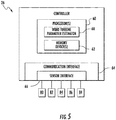
- the controller 26 may include one or more processor(s) 60 containing a wind turbine parameter estimator 68 and/or associated memory device(s) 62 configured to perform a variety of computer-implemented functions (e.g., performing the methods, steps, calculations and the like disclosed herein). Additionally, the controller 26 may also include a communications module 64 to facilitate communications between the controller 26 and the various components of the wind turbine 10. For instance, the communications module 64 may serve as an interface to permit the turbine controller 26 to transmit control signals to each pitch adjustment mechanism 32 for controlling the pitch angle of the rotor blades 22.
- the communications module 64 may include a sensor interface 66 (e.g., one or more analog-to-digital converters) to permit input signals transmitted from, for example, various sensors 80, 82, 84, 86, 88 of the wind turbine 10, to be converted into signals that can be understood and processed by the processors 60.
- the sensors 80, 82, 84, 86, 88 may be communicatively coupled to the communications module 64 using any suitable means.
- the sensors 80, 82, 84, 86, 88 are coupled to the sensor interface 66 via a wired connection.
- the sensors 80, 82, 84, 86, 88 may be coupled to the sensor interface 66 via a wireless connection, such as by using any suitable wireless communications protocol known in the art.
- the wind turbine parameter estimator 68 is configured to receive the signals from one or more sensors 80, 82, 84, 86, 88 that are representative of various operating conditions of the wind turbine 10.
- the operating conditions may consist of any combination of the following: a wind speed, a pitch angle, a generator speed, a power output, a torque output, a temperature, a pressure, a tip speed ratio, an air density, a rotor speed, a power coefficient, a torque coefficient, a thrust coefficient, a thrust, a thrust response, a blade bending moment, a shaft bending moment, a tower bending moment, a speed response, or similar.
- the wind turbine parameter estimator 68 may be considered software that utilizes the operating conditions to calculate, in real-time, various parameters of the wind turbine 10.
- the wind turbine parameter estimator 68 may include firmware that includes the software, which may be executed by the processor 60.
- the wind turbine parameter estimator 68 is configured to implement a control algorithm having a series of equations to determine various parameters.
- the equations are solved using the one or more operating conditions, one or more aerodynamic performance maps, one or more look-up tables (LUTs), or any combination thereof.
- the aerodynamic performance maps are dimensional or non-dimensional tables that describe rotor loading and performance (e.g. power, thrust, torque, or bending moment, or similar) under given conditions (e.g. density, wind speed, rotor speed, pitch angles, or similar).
- the aerodynamic performance maps may include: a power coefficient, a thrust coefficient, a torque coefficient, and/or partial derivatives with respect to pitch angle, rotor speed, or tip speed ratio.
- the aerodynamic performance maps can be dimensional power, thrust, and/or torque values instead of coefficients.
- the LUTs may include: aerodynamic performance parameters, blade bending load, tower bending load, shaft bending load, or any other turbine component load.
- processor refers not only to integrated circuits referred to in the art as being included in a computer, but also refers to a controller, a microcontroller, a microcomputer, a programmable logic controller (PLC), an application specific integrated circuit, a graphics processing unit (GPUs), and/or other programmable circuits now known or later developed.
- PLC programmable logic controller
- GPUs graphics processing unit
- the memory device(s) 62 may generally comprise memory element(s) including, but not limited to, computer readable medium (e.g., random access memory (RAM)), computer readable non-volatile medium (e.g., a flash memory), a floppy disk, a compact disc-read only memory (CD-ROM), a magneto-optical disk (MOD), a digital versatile disc (DVD) and/or other suitable memory elements.
- RAM random access memory
- computer readable non-volatile medium e.g., a flash memory
- CD-ROM compact disc-read only memory
- MOD magneto-optical disk
- DVD digital versatile disc
- Such memory device(s) 62 may generally be configured to store suitable computer-readable instructions that, when implemented by the processor(s) 60, configure the controller 26 to perform various functions as described herein.
- the sensors 80, 82, 84, 86, 88 as described herein may include blade sensors 88, e.g. for measuring a pitch angle of one of the rotor blades 22; generator sensors 84 for monitoring the generator 24 (e.g. torque, speed, acceleration and/or the power output); shaft sensors 86, e.g. for measuring rotor speed; tower sensors 82; and/or various wind sensors 80 for measuring various wind parameters, such as wind speed, wind peaks, wind turbulence, wind shear, changes in wind direction, air density, or similar.
- the sensors 80, 82, 84, 86, 88 may be located near the ground of the wind turbine 10, on the nacelle 16, or on a meteorological mast of the wind turbine 10.
- the sensors may be Micro Inertial Measurement Units (MIMUs), strain gauges, accelerometers, pressure sensors, angle of attack sensors, vibration sensors, Light Detecting and Ranging (LIDAR) sensors, camera systems, fiber optic systems, anemometers, wind vanes, barometers, Sonic Detection and Ranging (SODAR) sensors, infra lasers, radiometers, pitot tubes, rawinsondes, other optical sensors, and/or any other suitable sensors.
- MIMUs Micro Inertial Measurement Units
- LIDAR Light Detecting and Ranging
- SODAR Sonic Detection and Ranging
- the term "monitor” and variations thereof indicates that the various sensors 80, 82, 84, 86, 88 may be configured to provide a direct measurement of the parameters being monitored or an indirect measurement of such parameters.
- the sensors 80, 82, 84, 86, 88 may, for example, be used to generate signals relating to the parameter being monitored, which can then be utilized by the controller 26 to determine the actual parameter.
- the method 300 includes defining a first operating region associated with an unsaturated torque range.
- the method 300 includes defining a second operating region associated with a saturated torque range.
- the unsaturated torque range of the first operating region 309 includes torque values less than a torque constraint boundary 312 of the wind turbine 10
- the saturated torque range of the second operation region 310 includes torque values equal to or greater than the torque constraint boundary 312 of the wind turbine 10.
- the torque constraint boundary 312 of FIG. 7 illustrates a generic sliding mode surface (e.g.
- the second operating region 310 includes x values for which the derivative of TSR, namely TSR', with respect to time is greater than zero (i.e. TSR'>0) and the first operating region 309 includes x values for which TSR' is less than zero (i.e. TSR' ⁇ 0).
- the arrows along the torque constraint boundary 312 indicate the motion due to the chosen TSR', with the resultant trajectory 314 representing the actual motion achieved by switching TSR' values.
- the method 300 includes monitoring a torque output of the wind turbine 10, e.g. via the one or more sensors 80, 82, 84, 86, 88. Further, at 308, the method 300 includes continuously adjusting a tip-speed-ratio set point of the wind turbine 10 so as to operate the wind turbine 10 along a torque constraint boundary 312 of the first and second operating regions 309, 310. More specifically, in certain embodiments, the method 300 may include increasing the tip-speed-ratio set point when the torque output of the wind turbine 10 is within the second operating region 310 (i.e. the torque is saturated) and decreasing the tip-speed-ratio set point when the torque output of the wind turbine 10 is within the first operating region 309 (i.e. the torque is unsaturated).
- the torque constraint boundary 312 may be chosen based on when the wind turbine 10 begins pitching one or more of the rotor blades 22.
- the torque constraint boundary 312 may be determined by measuring torque and comparing it to a maximum torque limit.
- the torque saturation point occurs when a torque output of the wind turbine 10 reaches a rated torque without any other conditions (e.g. point 4 of FIG. 2 ).
- the controller 26 is configured to operate the wind turbine 10 according to a lower TSR set point while the torque output is non-saturated. Similarly, while the torque output is saturated, the controller 26 is configured to use a higher TSR set point. For example, in certain embodiments, the controller 26 detects whether one or more blades needs to be moved to a feather position and then allows the generator speed of the wind turbine 10 to increase by increasing the TSR target, which increases the power set point. The controller 26 then maintains the blades 22 at fine pitch (instead of pitching as it would without the TSR increase). At this time, the controller 26 switches modes and decreases the TSR so as to reduce the power set point.
- the controller 26 again detects that one or more blades 22 need to be moved to feather and continues to operate in this manner by moving along or oscillating over the saturation/non-saturation torque constraint boundary 312.
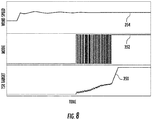
- FIG. 8 multiple graphs of one embodiment of wind speed, mode switching, and variable TSR target versus time, respectively, are illustrated.
- the graph illustrates when the wind turbine 10 is detecting saturation (i.e. when the controller 26 switches mode to a pitching mode and back to a fine-pitch mode).
- line 350 illustrates the TSR target that the controller 26 is trying to achieve, particularly illustrating how the target goes up and down as the turbine 10 is saturated/de-saturated (i.e., switching modes).
- line 352 illustrates the mode switching of the wind turbine 10
- line 354 illustrates the wind speed, which can be measured via one or more sensors or calculated via the controller 26.
- the controller 26 is configured to limit the increase in TSR as a function of maximum speed and maximum torque.
- the controller 26 may determine the boundary 312 of the first and second operating regions 309, 310 based upon when the wind turbine 10 switches operating modes. For example, in certain embodiments, switching operating modes may be defined by pitching one or more rotor blades 22 of the wind turbine 10. As such, in certain embodiments, when the wind turbine 10 reaches the torque constraint boundary 312 and starts pitching, the controller 26 is configured to continually adjust the tip-speed-ratio set point whenever the mode changes.
- the controller 26 is configured to operate the wind turbine 10 by sliding along the saturated torque boundary 312. More specifically, in certain embodiments, the controller 26 is configured to operate the wind turbine 10 by utilizing sliding-mode control.
- sliding mode control is a non-linear control method that alters the dynamics of the wind turbine system by application of a discontinuous control system that forces the system to slide along a cross-section of the system's normal behavior.
- the controller 26 is configured to increase the TSR when the wind turbine 10 is operating above rated torque and decrease the TSR when the wind turbine 10 is operating below rated torque.
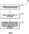
- the method 400 includes determining, via the processor 60, an initial tip-speed-ratio set point for the wind turbine 10.
- the method 400 includes monitoring, via one or more sensors 80, 82, 84, 86, 88, a torque output of the wind turbine 10.
- the method 400 includes continuously adjusting the tip-speed-ratio set point of the wind turbine 10 based the torque output so as to maximize a power output of the wind turbine 10.
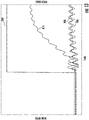
- FIGS. 10-14 various graphs illustrating advantages of operating the wind turbine based on variable TSR control according to the present disclosure are illustrated. More specifically, the graphs illustrate wind speed versus time plotted against a plurality of wind turbine operating conditions versus time, namely TSR ( FIG. 10 ), torque output ( FIG. 11 ), power output ( FIG. 12 ), pitch angle ( FIG. 13 ), and generator speed ( FIG. 14 ). As shown generally in FIGS. 10-14 , line 500 illustrates the wind speed for the wind turbine 10.
- variable TSR 506 matches the lower TSR 510. Further, for high wind speeds, the variable TSR 506 matches the higher TSR 508 with a transition region 502 where the TSR increases (i.e. sliding) along the saturated torque boundary. As shown in FIG. 11 , for lower wind speeds, the variable TSR torque value 606 matches the lower TSR torque value 610 (i.e. the torque saturates early). For high wind speeds, the variable TSR torque value 606 matches the higher TSR torque value 608 with a transition region 602 where the TSR torque value is increasing.
- variable TSR power level 706 matches both the lower TSR power level 710 and the higher TSR power level 708.
- the variable TSR power level 706 matches the higher TSR power level 708 with a transition region 602, where the TSR power level is increasing.
- the variable TSR power lever is higher than the lower TSR power level 710.
- variable pitch angle 806 matches the lower and higher TSR pitch angles 808, 810 and all angles are at fine pitch.
- the lower TSR pitch angle 810 has a higher pitch angle which is what the present invention attempts to avoid.
- the variable TSR pitch angle 806 matches the higher TSR pitch angle 808 during high wind speeds.
- the variable TSR generator speed 906 is illustrated as compared to the lower TSR generator speed 910 and the higher TSR generator speed 908.
Landscapes
- Engineering & Computer Science (AREA)
- Life Sciences & Earth Sciences (AREA)
- Sustainable Development (AREA)
- Sustainable Energy (AREA)
- Chemical & Material Sciences (AREA)
- Combustion & Propulsion (AREA)
- Mechanical Engineering (AREA)
- General Engineering & Computer Science (AREA)
- Physics & Mathematics (AREA)
- Fluid Mechanics (AREA)
- Wind Motors (AREA)
Abstract
Description
- The present invention relates generally to wind turbines, and more particularly, to a system and method for variable tip-speed-ratio control of a wind turbine.
- Wind power is considered one of the cleanest, most environmentally friendly energy sources presently available, and wind turbines have gained increased attention in this regard. A modem wind turbine typically includes a tower, a generator, a gearbox, a nacelle, and a rotor. The rotor typically includes a rotatable hub having one or more rotor blades attached thereto. A pitch bearing is typically configured operably between the hub and a blade root of the rotor blade to allow for rotation about a pitch axis. The rotor blades capture kinetic energy of wind using known airfoil principles. The rotor blades transmit the kinetic energy in the form of rotational energy so as to turn a shaft coupling the rotor blades to a gearbox, or if a gearbox is not used, directly to the generator. The generator then converts the mechanical energy to electrical energy that may be deployed to a utility grid.
- A plurality of wind turbines are commonly used in conjunction with one another to generate electricity and are commonly referred to as a "wind farm." Wind turbines on a wind farm typically include their own meteorological sensors that perform, for example, temperature, wind speed, wind direction, barometric pressure, and/or air density measurements. In addition, a separate meteorological mast or tower ("met mast") having higher quality meteorological instruments that can provide more accurate measurements at one point in the farm is commonly provided. The correlation of meteorological data with power output allows the empirical determination of a "power curve" for the individual wind turbines.
- For example,
FIG. 1 illustrates a typicaloperating power curve 100 for a wind turbine. As shown, a typical wind turbine operates along anoperating line 102 from a point "1" where wind speed is zero through points 2-3-4-5 (also known as the variable wind speed or knee region) to reach a ratedpower level 104 at point "5." After reaching the ratedpower level 104, additional wind speed does not result in additional turbine power output. - Generally, it is important to optimize the operation of the wind turbine, including blade energy capture, to reduce the cost of the energy produced. To this end, each turbine includes a control module, which attempts to maximize power output of the turbine in the face of varying wind and grid conditions, while satisfying constraints like sub-system ratings and component loads. Wind turbine loads are dependent on the wind speed, tip speed ratio (TSR), and/or pitch setting of the blade. TSR, as is understood by those of ordinary skill in the art, is the ratio of the tangential velocity of the blade tip to the actual wind speed. Pitch settings of the blades (i.e., the angle of attack of the airfoil shaped blade), provides one of the parameters utilized in wind turbine control. Based on the determined maximum power output, the control module controls the operation of various turbine components, such as the generator/power converter, the pitch system, the brakes, and the yaw mechanism to reach the maximum power efficiency.
- For example, wind turbine controllers are configured to adjust the rotational speed of the hub around which the blades rotate, i.e., the rotational speed, by adjusting the blade pitch in a manner that provides increased or decreased energy transfer from the wind, which accordingly is expected to adjust the rotor speed. As such, wind turbines are typically designed for a rated wind speed at which maximum thrust and maximum power generation occur.
- Generally, the farm controller sends a fixed TSR command to each of the turbines in the wind farm to control rotor speed. As shown in
FIG. 2 , a relationship exists between rotor speed and torque as illustrated by torque-speed curve 200. The torque-speed curve 200 illustrates differing operating curves wherecurve 202 extending along points 1-2-5-6 represents a low torque demand design whilecurve 204 extending along points 1-3-4-5-6 represents a high torque demand design. As shown, the lowtorque demand curve 202 will reach a ratedrotor speed 206 at point "2" where speed clipping will be observed prior to such turbine reaching its rated power at point "6." The hightorque demand curve 204, on the other hand, will reach its rated torque at point "4" (i.e. the point of torque saturation) and experience torque clipping prior to reaching its rated power at point "5." Thus, some wind turbines experience a loss of power in the variable wind speed region due to torque saturation occurring earlier than the maximum rotor speed. - Accordingly, improved systems and methods for controlling wind turbines that address the aforementioned issues are desired in the art. In particular, systems and methods for controlling wind turbines using variable tip-speed-ratio control would be advantageous.
- Various aspects and advantages of the invention will be set forth in part in the following description, or may be clear from the description, or may be learned through practice of the invention.
- In one aspect, the present subject matter is directed to a method for operating a wind turbine so as to increase power production of a wind turbine. The method includes defining a first operating region associated with an unsaturated torque range and a second operating region associated with a saturated torque range. Further, the first and second torque ranges are different. The method also includes continuously adjusting a tip-speed-ratio set point of the wind turbine so as to operate the wind turbine along a torque constraint boundary of the first and second operating regions.
- In one embodiment, the step of continuously adjusting the tip-speed-ratio set point of the wind turbine further includes increasing the tip-speed-ratio set point when the torque output of the wind turbine is within the second operating region. Similarly, the step of continuously adjusting the tip-speed-ratio set point of the wind turbine may also include decreasing the tip-speed-ratio set point when the torque output of the wind turbine is within the first operating region.
- In another embodiment, the method may also include determining the torque constraint boundary of the first and second operating regions based upon when the wind turbine switches operating modes. For example, in certain embodiments, switching operating modes may include pitching one or more rotor blades of the wind turbine.
- In further embodiments, the saturated torque range occurs when a torque of the wind turbine reaches a rated torque.
- In additional embodiments, the saturated torque range may include torque values less than the torque constraint boundary of the wind turbine, whereas the unsaturated torque range may include torque values equal to or greater than the torque constraint boundary of the wind turbine. In further embodiments, the step of continuously adjusting the tip-speed-ratio set point of the wind turbine occurs in a variable wind speed region of a power curve of the wind turbine.
- In another embodiment, the method may also include filtering (e.g. via a filter or otherwise) the tip-speed-ratio set point. In further embodiments, the step of continuously adjusting the tip-speed-ratio set point of the wind turbine may include utilizing sliding-mode control.
- In another aspect, the present disclosure may be directed to a system for increasing power production of a wind turbine. The system includes one or more sensors configured to monitor a torque output of the wind turbine and a controller communicatively coupled to a processor. Further, the processor is configured to perform one or more operations. The operations includes defining a first operating region associated with an unsaturated torque range, defining a second operating region associated with a saturated torque range, and continuously adjusting a tip-speed-ratio set point of the wind turbine so as to operate the wind turbine along a torque constraint boundary of the first and second operating regions, e.g. in the variable wind speed region of the power curve.
- In yet another aspect, the present disclosure is directed to a method for operating a wind turbine based on a variable tip-speed-ratio. The method includes determining, via a processor, an initial tip-speed-ratio set point for the wind turbine. Another step includes monitoring, via one or more sensors, a torque output of the wind turbine. The method also includes continuously adjusting the tip-speed-ratio set point of the wind turbine based the torque output so as to maximize a power output of the wind turbine.
- In one embodiment, the step of monitoring the torque output of the wind turbine may include monitoring the torque output during a first operating region associated with an unsaturated torque range and monitoring the torque output during a second operating region associated with a saturated torque range. As such, in further embodiments, the step of continuously adjusting the tip-speed-ratio set point of the wind turbine based the torque output may include continuously adjusting the tip-speed-ratio set point so as to operate the wind turbine along a torque constraint boundary of the first and second operating regions. It should be understood that the method may also include any of the additional steps and/or features described herein.
- Various features, aspects and advantages of the present invention will become better understood with reference the following description and appended claims. The accompanying drawings, which are incorporated in and constitute a part of this specification, illustrate the embodiments of the invention and, together with the description, serve to explain the principles of the invention. In the drawings:
-
FIG. 1 illustrates a typical operating power curve for a wind turbine; -
FIG. 2 illustrates torque-speed curves illustrating differing operating curves between low torque demand and high torque demand; -
FIG. 3 is a perspective view of a wind turbine according to one embodiment of the present disclosure; -
FIG. 4 illustrates a perspective, internal view of a nacelle of a wind turbine according to one embodiment of the present disclosure; -
FIG. 5 illustrates a schematic diagram of one embodiment of suitable components that may be included within a controller of a wind turbine according to the present disclosure; -
FIG. 6 illustrates a flow diagram of one embodiment of a method for increasing power production of a wind turbine in the variable wind speed region of the power curve according to the present disclosure; -
FIG. 7 illustrates a graph of one embodiment of torque (y-axis) versus TSR (x-axis) according to the present disclosure; -
FIG. 8 illustrates multiple graphs of wind speed, mode, and TSR target versus time according to the present disclosure; -
FIG. 9 illustrates a flow diagram of one embodiment of a method for operating a wind turbine based on a variable tip-speed-ratio according to the present disclosure; -
FIG. 10 illustrates a graph of wind speed and actual TSR versus time, particularly illustrating various benefits of operating the wind turbine with a variable TSR, according to the present disclosure; -
FIG. 11 illustrates a graph of wind speed and generator torque versus time, particularly illustrating various benefits of operating the wind turbine with a variable TSR torque value, according to the present disclosure; -
FIG. 12 illustrates a graph of wind speed and power versus time, particularly illustrating various benefits of operating the wind turbine with a variable TSR power level, according to the present disclosure; -
FIG. 13 illustrates a graph of wind speed and pitch angle versus time, particularly illustrating various benefits of operating the wind turbine with a variable TSR pitch angle, according to the present disclosure; and -
FIG. 14 illustrates a graph of wind speed and generator speed versus time, particularly illustrating various benefits of operating the wind turbine with a variable TSR generator speed, according to the present disclosure. - Reference now will be made in detail to embodiments of the invention, one or more examples of which are illustrated in the drawings. Each example is provided by way of explanation of the invention, not limitation of the invention. In fact, it will be apparent to those skilled in the art that various modifications and variations can be made in the present invention without departing from the scope or spirit of the invention. For instance, features illustrated or described as part of one embodiment can be used with another embodiment to yield a still further embodiment. Thus, it is intended that the present invention covers such modifications and variations as come within the scope of the appended claims and their equivalents.
- Generally, the present subject matter is directed to a system and method for operating a wind turbine so as to increase power production by utilizing variable tip-speed-ratio control. Typically, a wind turbine controller uses a fixed tip-speed-ratio (TSR) target to compute the desired speed of the turbine. In some instances, however, a turbine may reach torque saturation before speed saturation and hence start pitching to control the speed. In this way, the wind turbine may lose power in the variable wind-speed region of the power curve. In addition, for some wake control schemes, the controller may receive an external TSR target lower than the TSR for normal operation. The lower TSR leads to even earlier pitching activity and loss of power (and may also lead to previously non-existing early torque saturation).
- Accordingly, the wind turbine controller of the present disclosure is configured to ignore an external TSR target and maintain the normal TSR target when reaching this torque saturation area. Furthermore, the controller of the present disclosure addresses any instances of early pitching activity due to torque-before-speed saturation when using the normal and fixed TSR target by allowing the TSR target to increase to above normal values when torque saturation is reached. For example, in one embodiment, the controller defines first and second operation regions with each region being associated with saturated and unsaturated torque ranges. As such, the controller is configured to operate the wind turbine along a torque constraint boundary of the first and second operation regions by continuously adjusting a tip-speed-ratio set point of the wind turbine.
- The various embodiments of the system and method described herein provide numerous advantages not present in the prior art. For example, as mentioned, the present disclosure provides improved power production in the variable wind speed region of the power curve. As such, wind farms and/or wind turbines operated according to the present disclosure provide an overall increase in annual energy production (AEP) when compared to prior art systems.
- Referring now to the drawings,
FIG. 3 illustrates a perspective view of one embodiment of awind turbine 10. As shown, thewind turbine 10 includes atower 12 extending from asupport surface 14, anacelle 16 mounted on thetower 12, and arotor 18 coupled to thenacelle 16. Therotor 18 includes arotatable hub 20 and at least one rotor blade 22coupled to and extending outwardly from thehub 20. For example, in the illustrated embodiment, therotor 18 includes threerotor blades 22. However, in an alternative embodiment, therotor 18 may include more or less than threerotor blades 22. Eachrotor blade 22 may be spaced about thehub 20 to facilitate rotating therotor 18 to enable kinetic energy to be transferred from the wind into usable mechanical energy, and subsequently, electrical energy. For instance, thehub 20 may be rotatably coupled to an electric generator 24 (FIG. 4 ) positioned within thenacelle 16 to permit electrical energy to be produced. - Referring now to
FIG. 4 , a simplified, internal view of one embodiment of thenacelle 16 of thewind turbine 10 is illustrated. As shown, agenerator 24 may be disposed within thenacelle 16. In general, thegenerator 24 may be coupled to therotor 18 of thewind turbine 10 for generating electrical power from the rotational energy generated by therotor 18. For example, therotor 18 may include amain rotor shaft 40 coupled to thehub 20 for rotation therewith. Thegenerator 24 may then be coupled to therotor shaft 40 such that rotation of therotor shaft 40 drives thegenerator 24. For instance, in the illustrated embodiment, thegenerator 24 includes agenerator shaft 42 rotatably coupled to therotor shaft 40 through agearbox 44. However, in other embodiments, it should be appreciated that thegenerator shaft 42 may be rotatably coupled directly to therotor shaft 40. Alternatively, thegenerator 24 may be directly rotatably coupled to the rotor shaft 40 (often referred to as a "direct-drive wind turbine"). It should be appreciated that therotor shaft 40 may generally be supported within the nacelle by a support frame orbedplate 46 positioned atop thewind turbine tower 12. - As shown in
FIGS. 3 and4 , thewind turbine 10 may also include a turbine control system or aturbine controller 26 centralized within thenacelle 16. For example, as shown, theturbine controller 26 is disposed within acontrol cabinet 52 mounted to a portion of thenacelle 16. However, it should be appreciated that theturbine controller 26 may be disposed at any location on or in thewind turbine 10, at any location on thesupport surface 14 or generally at any other location. - The
turbine controller 26 may generally be configured to control the various operating modes (e.g., start-up or shut-down sequences) and/or components of thewind turbine 10. For example, thecontroller 26 may be configured to control the blade pitch or pitch angle of each of the rotor blades 22 (i.e., an angle that determines a perspective of therotor blades 22 with respect to thedirection 28 of the wind) to ultimately control power output of thewind turbine 10. More specifically, thecontroller 26 may control the pitch angle of therotor blades 22, either individually or simultaneously, by transmitting suitable control signals/commands to various pitch drives or pitch adjustment mechanisms 32 (FIG. 4 ) of thewind turbine 10. Specifically, therotor blades 22 may be rotatably mounted to thehub 20 by one or more pitch bearing(s) (not illustrated) such that the pitch angle may be adjusted by rotating therotor blades 22 about their pitch axes 34 using thepitch adjustment mechanisms 32. Thecontroller 26 may also be communicatively coupled to the yaw drive mechanism(s) 38 of thewind turbine 10 for controlling and/or altering the yaw direction of thenacelle 16 relative to the direction 28 (FIG. 3 ) of the wind. - Still further, the
turbine controller 26 may be configured to control the torque of thegenerator 24. For example, thecontroller 26 may be configured to transmit control signals/commands to thegenerator 24 in order to modulate the magnetic flux produced within thegenerator 24, thus adjusting the torque demand on thegenerator 24. It should additionally be understood that thecontroller 26 may be a singular controller or include various components, such as pitch controllers and/or yaw controllers, which communicate with a central controller for specifically controlling pitch and yaw as discussed. - Referring now to
FIG. 5 , there is illustrated a block diagram of one embodiment of suitable components that may be included within theturbine controller 26 in accordance with aspects of the present subject matter. As shown, thecontroller 26 may include one or more processor(s) 60 containing a windturbine parameter estimator 68 and/or associated memory device(s) 62 configured to perform a variety of computer-implemented functions (e.g., performing the methods, steps, calculations and the like disclosed herein). Additionally, thecontroller 26 may also include acommunications module 64 to facilitate communications between thecontroller 26 and the various components of thewind turbine 10. For instance, thecommunications module 64 may serve as an interface to permit theturbine controller 26 to transmit control signals to eachpitch adjustment mechanism 32 for controlling the pitch angle of therotor blades 22. Moreover, thecommunications module 64 may include a sensor interface 66 (e.g., one or more analog-to-digital converters) to permit input signals transmitted from, for example,various sensors wind turbine 10, to be converted into signals that can be understood and processed by theprocessors 60. It should be appreciated that thesensors communications module 64 using any suitable means. For example, as shown inFIG. 5 , thesensors sensor interface 66 via a wired connection. However, in other embodiments, thesensors sensor interface 66 via a wireless connection, such as by using any suitable wireless communications protocol known in the art. - In certain embodiments, the wind
turbine parameter estimator 68 is configured to receive the signals from one ormore sensors wind turbine 10. The operating conditions may consist of any combination of the following: a wind speed, a pitch angle, a generator speed, a power output, a torque output, a temperature, a pressure, a tip speed ratio, an air density, a rotor speed, a power coefficient, a torque coefficient, a thrust coefficient, a thrust, a thrust response, a blade bending moment, a shaft bending moment, a tower bending moment, a speed response, or similar. Further, the windturbine parameter estimator 68 may be considered software that utilizes the operating conditions to calculate, in real-time, various parameters of thewind turbine 10. In addition, the windturbine parameter estimator 68 may include firmware that includes the software, which may be executed by theprocessor 60. - Accordingly, in one embodiment, the wind
turbine parameter estimator 68 is configured to implement a control algorithm having a series of equations to determine various parameters. As such, the equations are solved using the one or more operating conditions, one or more aerodynamic performance maps, one or more look-up tables (LUTs), or any combination thereof. In one embodiment, for example, the aerodynamic performance maps are dimensional or non-dimensional tables that describe rotor loading and performance (e.g. power, thrust, torque, or bending moment, or similar) under given conditions (e.g. density, wind speed, rotor speed, pitch angles, or similar). As such, the aerodynamic performance maps may include: a power coefficient, a thrust coefficient, a torque coefficient, and/or partial derivatives with respect to pitch angle, rotor speed, or tip speed ratio. Alternatively, the aerodynamic performance maps can be dimensional power, thrust, and/or torque values instead of coefficients. In various embodiments, the LUTs may include: aerodynamic performance parameters, blade bending load, tower bending load, shaft bending load, or any other turbine component load. - As used herein, the term "processor" refers not only to integrated circuits referred to in the art as being included in a computer, but also refers to a controller, a microcontroller, a microcomputer, a programmable logic controller (PLC), an application specific integrated circuit, a graphics processing unit (GPUs), and/or other programmable circuits now known or later developed. Additionally, the memory device(s) 62 may generally comprise memory element(s) including, but not limited to, computer readable medium (e.g., random access memory (RAM)), computer readable non-volatile medium (e.g., a flash memory), a floppy disk, a compact disc-read only memory (CD-ROM), a magneto-optical disk (MOD), a digital versatile disc (DVD) and/or other suitable memory elements. Such memory device(s) 62 may generally be configured to store suitable computer-readable instructions that, when implemented by the processor(s) 60, configure the
controller 26 to perform various functions as described herein. - Referring back to
FIG. 4 , thesensors blade sensors 88, e.g. for measuring a pitch angle of one of therotor blades 22;generator sensors 84 for monitoring the generator 24 (e.g. torque, speed, acceleration and/or the power output);shaft sensors 86, e.g. for measuring rotor speed;tower sensors 82; and/orvarious wind sensors 80 for measuring various wind parameters, such as wind speed, wind peaks, wind turbulence, wind shear, changes in wind direction, air density, or similar. Further, thesensors wind turbine 10, on thenacelle 16, or on a meteorological mast of thewind turbine 10. Moreover, it should also be understood that any other number or type of sensors may be employed and at any location. For example, the sensors may be Micro Inertial Measurement Units (MIMUs), strain gauges, accelerometers, pressure sensors, angle of attack sensors, vibration sensors, Light Detecting and Ranging (LIDAR) sensors, camera systems, fiber optic systems, anemometers, wind vanes, barometers, Sonic Detection and Ranging (SODAR) sensors, infra lasers, radiometers, pitot tubes, rawinsondes, other optical sensors, and/or any other suitable sensors.
It should be appreciated that, as used herein, the term "monitor" and variations thereof indicates that thevarious sensors sensors controller 26 to determine the actual parameter. - Referring now to
FIG. 6 , a flow diagram of one embodiment of amethod 300 for improving power production of awind turbine 10 is illustrated. As shown at 302, themethod 300 includes defining a first operating region associated with an unsaturated torque range. At 304, themethod 300 includes defining a second operating region associated with a saturated torque range. For example, as shown inFIG. 7 , the unsaturated torque range of thefirst operating region 309 includes torque values less than atorque constraint boundary 312 of thewind turbine 10, whereas the saturated torque range of thesecond operation region 310 includes torque values equal to or greater than thetorque constraint boundary 312 of thewind turbine 10. More specifically, thetorque constraint boundary 312 ofFIG. 7 illustrates a generic sliding mode surface (e.g. s(x) = 0), wherein the axes are x1, x2, ... xn, where x = [x1, x2, ... xn] is a vector. As such, thesecond operating region 310 includes x values for which the derivative of TSR, namely TSR', with respect to time is greater than zero (i.e. TSR'>0) and thefirst operating region 309 includes x values for which TSR' is less than zero (i.e. TSR'<0). In addition, the arrows along thetorque constraint boundary 312 indicate the motion due to the chosen TSR', with theresultant trajectory 314 representing the actual motion achieved by switching TSR' values. - At 306, the
method 300 includes monitoring a torque output of thewind turbine 10, e.g. via the one ormore sensors method 300 includes continuously adjusting a tip-speed-ratio set point of thewind turbine 10 so as to operate thewind turbine 10 along atorque constraint boundary 312 of the first andsecond operating regions method 300 may include increasing the tip-speed-ratio set point when the torque output of thewind turbine 10 is within the second operating region 310 (i.e. the torque is saturated) and decreasing the tip-speed-ratio set point when the torque output of thewind turbine 10 is within the first operating region 309 (i.e. the torque is unsaturated). For example, thetorque constraint boundary 312 may be chosen based on when thewind turbine 10 begins pitching one or more of therotor blades 22. In additional embodiments, thetorque constraint boundary 312 may be determined by measuring torque and comparing it to a maximum torque limit. As used herein, the torque saturation point occurs when a torque output of thewind turbine 10 reaches a rated torque without any other conditions (e.g. point 4 ofFIG. 2 ). - As such, in certain embodiments, the
controller 26 is configured to operate thewind turbine 10 according to a lower TSR set point while the torque output is non-saturated. Similarly, while the torque output is saturated, thecontroller 26 is configured to use a higher TSR set point. For example, in certain embodiments, thecontroller 26 detects whether one or more blades needs to be moved to a feather position and then allows the generator speed of thewind turbine 10 to increase by increasing the TSR target, which increases the power set point. Thecontroller 26 then maintains theblades 22 at fine pitch (instead of pitching as it would without the TSR increase). At this time, thecontroller 26 switches modes and decreases the TSR so as to reduce the power set point. Thecontroller 26 again detects that one ormore blades 22 need to be moved to feather and continues to operate in this manner by moving along or oscillating over the saturation/non-saturationtorque constraint boundary 312. For example, as shown inFIG. 8 , multiple graphs of one embodiment of wind speed, mode switching, and variable TSR target versus time, respectively, are illustrated. As shown, the graph illustrates when thewind turbine 10 is detecting saturation (i.e. when thecontroller 26 switches mode to a pitching mode and back to a fine-pitch mode). More specifically,line 350 illustrates the TSR target that thecontroller 26 is trying to achieve, particularly illustrating how the target goes up and down as theturbine 10 is saturated/de-saturated (i.e., switching modes). Further,line 352 illustrates the mode switching of thewind turbine 10 andline 354 illustrates the wind speed, which can be measured via one or more sensors or calculated via thecontroller 26. - In certain embodiments, if the
wind turbine 10 is already operating at a maximum rotor or generator speed at torque saturation, an increase in the TSR will have little to no effect. In such embodiments, thecontroller 26 is configured to limit the increase in TSR as a function of maximum speed and maximum torque. - In additional embodiments, the
controller 26 may determine theboundary 312 of the first andsecond operating regions wind turbine 10 switches operating modes. For example, in certain embodiments, switching operating modes may be defined by pitching one ormore rotor blades 22 of thewind turbine 10. As such, in certain embodiments, when thewind turbine 10 reaches thetorque constraint boundary 312 and starts pitching, thecontroller 26 is configured to continually adjust the tip-speed-ratio set point whenever the mode changes. - As such, the
controller 26 is configured to operate thewind turbine 10 by sliding along the saturatedtorque boundary 312. More specifically, in certain embodiments, thecontroller 26 is configured to operate thewind turbine 10 by utilizing sliding-mode control. As used herein, sliding mode control is a non-linear control method that alters the dynamics of the wind turbine system by application of a discontinuous control system that forces the system to slide along a cross-section of the system's normal behavior. As such, thecontroller 26 is configured to increase the TSR when thewind turbine 10 is operating above rated torque and decrease the TSR when thewind turbine 10 is operating below rated torque. - Referring now to
FIG. 9 , a flow diagram of one embodiment of amethod 400 for operating thewind turbine 10 based on a variable tip-speed-ratio is illustrated. As shown at 402, themethod 400 includes determining, via theprocessor 60, an initial tip-speed-ratio set point for thewind turbine 10. At 404, themethod 400 includes monitoring, via one ormore sensors wind turbine 10. At 406, themethod 400 includes continuously adjusting the tip-speed-ratio set point of thewind turbine 10 based the torque output so as to maximize a power output of thewind turbine 10. - Referring now to
FIGS. 10-14 , various graphs illustrating advantages of operating the wind turbine based on variable TSR control according to the present disclosure are illustrated. More specifically, the graphs illustrate wind speed versus time plotted against a plurality of wind turbine operating conditions versus time, namely TSR (FIG. 10 ), torque output (FIG. 11 ), power output (FIG. 12 ), pitch angle (FIG. 13 ), and generator speed (FIG. 14 ). As shown generally inFIGS. 10-14 ,line 500 illustrates the wind speed for thewind turbine 10. - More specifically, as shown in
FIG. 10 , for low wind speeds, thevariable TSR 506 matches thelower TSR 510. Further, for high wind speeds, thevariable TSR 506 matches thehigher TSR 508 with atransition region 502 where the TSR increases (i.e. sliding) along the saturated torque boundary. As shown inFIG. 11 , for lower wind speeds, the variableTSR torque value 606 matches the lower TSR torque value 610 (i.e. the torque saturates early). For high wind speeds, the variableTSR torque value 606 matches the higher TSR torque value 608 with atransition region 602 where the TSR torque value is increasing. - As shown in
FIG. 12 , for lower wind speeds, the variableTSR power level 706 matches both the lowerTSR power level 710 and the higherTSR power level 708. For high wind speeds, however, the variableTSR power level 706 matches the higherTSR power level 708 with atransition region 602, where the TSR power level is increasing. Further, as shown for high wind speeds, the variable TSR power lever is higher than the lowerTSR power level 710. As such, by adjusting the TSR according to the present disclosure, power production is improved in the variable wind speed region of the power curve. - Referring to
FIG. 13 , for low wind speeds, thevariable pitch angle 806 matches the lower and higher TSR pitch angles 808, 810 and all angles are at fine pitch. For high wind speeds, the lowerTSR pitch angle 810 has a higher pitch angle which is what the present invention attempts to avoid. As such, the variableTSR pitch angle 806 matches the higherTSR pitch angle 808 during high wind speeds. As shown inFIG. 14 , the variableTSR generator speed 906 is illustrated as compared to the lower TSR generator speed 910 and the higherTSR generator speed 908. - This written description uses examples to disclose the invention, including the preferred mode, and also to enable any person skilled in the art to practice the invention, including making and using any devices or systems and performing any incorporated methods. The patentable scope of the invention is defined by the claims, and may include other examples that occur to those skilled in the art. Such other examples are intended to be within the scope of the claims if they include structural elements that do not differ from the literal language of the claims, or if they include equivalent structural elements with insubstantial differences from the literal languages of the claims.
- Various aspects and embodiments of the present invention are defined by the following numbered clauses:
- 1. A method for operating a wind turbine so as to increase power production, the method comprising:
- defining a first operating region associated with an unsaturated torque range;
- defining a second operating region associated with a saturated torque range;
- monitoring a torque output of the wind turbine; and,
- continuously adjusting a tip-speed-ratio set point of the wind turbine based on the torque output so as to operate the wind turbine along a torque constraint boundary of the first and second operating regions.
- 2. The method of clause 1, wherein continuously adjusting the tip-speed-ratio set point of the wind turbine further comprises increasing the tip-speed-ratio set point when the torque output of the wind turbine is within the second operating region.
- 3. The method of any preceding clause, wherein continuously adjusting the tip-speed-ratio set point of the wind turbine further comprises decreasing the tip-speed-ratio set point when the torque output of the wind turbine is within the first operating region.
- 4. The method of any preceding clause, further comprising determining the torque constraint boundary of the first and second operating regions based upon when the wind turbine switches operating modes.
- 5. The method of any preceding clause, wherein switching operating modes further comprises pitching one or more rotor blades of the wind turbine.
- 6. The method of any preceding clause, wherein the saturated torque range occurs when the torque output of the wind turbine reaches a rated torque of the wind turbine.
- 7. The method of any preceding clause, further comprising continuously adjusting the tip-speed-ratio set point of the wind turbine in a variable wind speed region of a power curve of the wind turbine.
- 8. The method of any preceding clause, wherein the unsaturated torque range comprises torque values less than the torque constraint boundary of the wind turbine.
- 9. The method of any preceding clause, wherein the saturated torque range comprises torque values equal to or greater than the torque constraint boundary of the wind turbine.
- 10. The method of any preceding clause, further comprising filtering the tip-speed-ratio set point.
- 11. The method of any preceding clause, wherein continuously adjusting the tip-speed-ratio set point of the wind turbine further comprises utilizing sliding-mode control.
- 12. A system for increasing power production of a wind turbine, the system comprising:
- one or more sensors configured to monitor a torque output of the wind turbine;
- a controller communicatively coupled to a processor, the processor configured to perform one or more operations, the operations comprising:
- defining a first operating region associated with an unsaturated torque range;
- defining a second operating region associated with a saturated torque range;
- continuously adjusting a tip-speed-ratio set point of the wind turbine based on the torque output so as to operate the wind turbine along a torque constraint boundary of the first and second operating regions.
- 13. A method for operating a wind turbine based on a variable tip-speed-ratio, the method comprising:
- determining, via a processor, an initial tip-speed-ratio set point for the wind turbine;
- monitoring, via one or more sensors, a torque output of the wind turbine; and,
- continuously adjusting the tip-speed-ratio set point of the wind turbine based the torque output so as to maximize a power output of the wind turbine.
- 14. The method of any preceding clause, wherein monitoring the torque output of the wind turbine further comprises monitoring the torque output during a first operating region associated with a saturated torque range and monitoring the torque output during a second operating region associated with an unsaturated torque range.
- 15. The method of any preceding clause, wherein continuously adjusting the tip-speed-ratio set point of the wind turbine based the torque output further comprises continuously adjusting the tip-speed-ratio set point so as to operate the wind turbine along a torque constraint boundary of the first and second operating regions.
- 16. The method of any preceding clause, wherein continuously adjusting the tip-speed-ratio set point of the wind turbine based the torque output further comprises:
- increasing the tip-speed-ratio set point when the torque output is within the second operating region, and
- decreasing the tip-speed-ratio set point when the torque output is within the first operating region.
- 17. The method of any preceding clause, further comprising determining the torque constraint boundary of the first and second operating regions based upon when the wind turbine switches operating modes.
- 18. The method of any preceding clause, wherein switching operating modes further comprises reaching a torque constraint of the wind turbine and pitching one or more rotor blades of the wind turbine.
- 19. The method of any preceding clause, wherein the unsaturated torque range comprises torque values less than the torque constraint boundary of the wind turbine, and the saturated torque range comprises torque values equal to or greater than the torque constraint boundary of the wind turbine.
- 20. The method of any preceding clause, further comprising filtering the tip-speed-ratio set point.
Claims (15)
- A method (300) for operating a wind turbine (10) so as to increase power production, the method comprising:defining (302) a first operating region (309) associated with an unsaturated torque range;defining (304) a second operating region (310) associated with a saturated torque range;monitoring (306) a torque output of the wind turbine (10); andcontinuously adjusting (308) a tip-speed-ratio set point of the wind turbine (10) based on the torque output so as to operate the wind turbine (10) along a torque constraint boundary (312) of the first and second operating regions (309, 310).
- The method (300) of claim 1, wherein continuously adjusting the tip-speed-ratio set point of the wind turbine (10) further comprises increasing the tip-speed-ratio set point when the torque output of the wind turbine (10) is within the second operating region (310).
- The method (300) of any preceding claim, wherein continuously adjusting the tip-speed-ratio set point of the wind turbine (10) further comprises decreasing the tip-speed-ratio set point when the torque output of the wind turbine (10) is within the first operating region (310).
- The method (300) of any preceding claim, further comprising determining the torque constraint boundary (312) of the first and second operating regions (309, 310) based upon when the wind turbine (10) switches operating modes.
- The method (300) of any preceding claim, wherein switching operating modes further comprises pitching one or more rotor blades (22) of the wind turbine (10).
- The method (300) of any preceding claim, wherein the saturated torque range occurs when the torque output of the wind turbine (10) reaches a rated torque of the wind turbine (10).
- The method (300) of any preceding claim, further comprising continuously adjusting the tip-speed-ratio set point of the wind turbine (10) in a variable wind speed region of a power curve of the wind turbine (10).
- The method (300) of any preceding claim, wherein the unsaturated torque range comprises torque values less than the torque constraint boundary (312) of the wind turbine (10).
- The method (300) of any preceding claim, wherein the saturated torque range comprises torque values equal to or greater than the torque constraint boundary (312) of the wind turbine (10).
- The method (300) of any preceding claim, further comprising filtering the tip-speed-ratio set point.
- The method (300) of any preceding claim, wherein continuously adjusting the tip-speed-ratio set point of the wind turbine (10) further comprises utilizing sliding-mode control.
- A system for increasing power production of a wind turbine (10), the system comprising:one or more sensors (80, 82, 84, 86, 88) configured to monitor a torque output of the wind turbine (10);a controller (26) communicatively coupled to a processor (60), the processor (60) configured to perform one or more operations, the operations comprising:defining a first operating region (309) associated with an unsaturated torque range;defining a second operating region (310) associated with a saturated torque range;continuously adjusting a tip-speed-ratio set point of the wind turbine (10) based on the torque output so as to operate the wind turbine (10) along a torque constraint boundary (312) of the first and second operating regions (309, 310).
- A method (300) for operating a wind turbine (10) based on a variable tip-speed-ratio, the method comprising:determining, via a processor, an initial tip-speed-ratio set point for the wind turbine (10);monitoring, via one or more sensors (80, 82, 84, 86, 88), a torque output of the wind turbine (10); andcontinuously adjusting the tip-speed-ratio set point of the wind turbine (10) based the torque output so as to maximize a power output of the wind turbine (10).
- The method (300) of claim 13, wherein monitoring the torque output of the wind turbine (10) further comprises monitoring the torque output during a first operating region (309) associated with a saturated torque range and monitoring the torque output during a second operating region (310) associated with an unsaturated torque range.
- The method (300) of claim 13 or claim 14, wherein continuously adjusting the tip-speed-ratio set point of the wind turbine (10) based the torque output further comprises continuously adjusting the tip-speed-ratio set point so as to operate the wind turbine (10) along a torque constraint boundary (312) of the first and second operating regions (309, 310).
Applications Claiming Priority (1)
| Application Number | Priority Date | Filing Date | Title |
|---|---|---|---|
| US14/656,870 US10473088B2 (en) | 2015-03-13 | 2015-03-13 | System and method for variable tip-speed-ratio control of a wind turbine |
Publications (2)
| Publication Number | Publication Date |
|---|---|
| EP3067556A1 true EP3067556A1 (en) | 2016-09-14 |
| EP3067556B1 EP3067556B1 (en) | 2021-06-30 |
Family
ID=55527431
Family Applications (1)
| Application Number | Title | Priority Date | Filing Date |
|---|---|---|---|
| EP16159952.7A Active EP3067556B1 (en) | 2015-03-13 | 2016-03-11 | System and method for variable tip-speed-ratio control of a wind turbine |
Country Status (7)
| Country | Link |
|---|---|
| US (1) | US10473088B2 (en) |
| EP (1) | EP3067556B1 (en) |
| CN (1) | CN106089581B (en) |
| BR (1) | BR102016005375B1 (en) |
| CA (1) | CA2923294C (en) |
| DK (1) | DK3067556T3 (en) |
| ES (1) | ES2892527T3 (en) |
Families Citing this family (15)
| Publication number | Priority date | Publication date | Assignee | Title |
|---|---|---|---|---|
| WO2015192853A1 (en) * | 2014-06-20 | 2015-12-23 | Mita-Teknik A/S | System for thrust-limiting of wind turbines |
| DE102016215533A1 (en) * | 2016-08-18 | 2018-02-22 | Wobben Properties Gmbh | Measuring arrangement of a wind turbine |
| JP2018059450A (en) * | 2016-10-06 | 2018-04-12 | 株式会社日立製作所 | Wind power generation device and control method of wind power generation device |
| US10519929B2 (en) * | 2016-11-09 | 2019-12-31 | General Electric Company | System and method for minimizing energy loss due to yaw untwist of a wind turbine |
| US11136961B2 (en) | 2017-06-01 | 2021-10-05 | General Electric Company | System and method for optimizing power output of a wind turbine during an operational constraint |
| US20190072072A1 (en) * | 2017-09-06 | 2019-03-07 | Envision Energy Usa Ltd. | Variable speed control of wind turbine generator based on estimated torque |
| DE102018100727A1 (en) * | 2018-01-15 | 2019-07-18 | Wobben Properties Gmbh | Method for controlling a wind turbine and wind turbine |
| US10774811B2 (en) | 2018-05-01 | 2020-09-15 | General Electric Company | Induction controlled wind turbine |
| US10605228B2 (en) | 2018-08-20 | 2020-03-31 | General Electric Company | Method for controlling operation of a wind turbine |
| CN110966142B (en) * | 2018-09-28 | 2021-06-22 | 北京金风科创风电设备有限公司 | Control method and device for wind generating set |
| CN109779850B (en) * | 2019-02-18 | 2022-01-11 | 中国空气动力研究与发展中心低速空气动力研究所 | Tip speed ratio control system and method for wind turbine wind wheel test |
| CN114060208A (en) * | 2020-07-29 | 2022-02-18 | 北京金风科创风电设备有限公司 | Control method, device and equipment of wind generating set and storage medium |
| EP4386201B1 (en) * | 2022-12-12 | 2025-06-04 | Vestas Wind Systems A/S | Controlling a wind turbine with an updated power coefficient adjusted by a degradation function |
| CN119737278B (en) * | 2024-11-26 | 2025-10-31 | 云南成昌新能源有限公司 | Intelligent wind power generation monitoring system |
| CN120257861B (en) * | 2025-06-06 | 2025-08-22 | 哈尔滨工业大学(深圳)(哈尔滨工业大学深圳科技创新研究院) | Large and ultra-large wind turbine generator design method based on compressible flow principle |
Citations (2)
| Publication number | Priority date | Publication date | Assignee | Title |
|---|---|---|---|---|
| EP0223729A1 (en) * | 1985-11-18 | 1987-05-27 | United Technologies Corporation | Torque control for a variable speed wind turbine |
| EP2096300A2 (en) * | 2008-02-29 | 2009-09-02 | General Electric Company | Method of controlling the tip speed ratio of wind turbine blades |
Family Cites Families (17)
| Publication number | Priority date | Publication date | Assignee | Title |
|---|---|---|---|---|
| EP0023729A1 (en) | 1979-08-07 | 1981-02-11 | Institut Dequalex, Institut Pour La Valorisation Des Dechets De Qualites Exploitables | Process for detinning tin coated scrap |
| US5155375A (en) | 1991-09-19 | 1992-10-13 | U.S. Windpower, Inc. | Speed control system for a variable speed wind turbine |
| US5798631A (en) | 1995-10-02 | 1998-08-25 | The State Of Oregon Acting By And Through The State Board Of Higher Education On Behalf Of Oregon State University | Performance optimization controller and control method for doubly-fed machines |
| DE10127451C5 (en) * | 2001-06-07 | 2016-09-01 | Aloys Wobben | Method for controlling a wind energy plant |
| US7261672B2 (en) | 2003-03-19 | 2007-08-28 | The Regents Of The University Of California | Method and system for controlling rate of change of ratio in a continuously variable transmission |
| EP1665494B2 (en) | 2003-09-03 | 2023-06-28 | Siemens Gamesa Renewable Energy Service GmbH | Method for operating or controlling a wind turbine and method for providing primary control power by means of wind turbines |
| US7504738B2 (en) | 2005-09-29 | 2009-03-17 | General Electric Company | Wind turbine and method for operating same |
| DE102005059888C5 (en) | 2005-12-15 | 2016-03-10 | Nordex Energy Gmbh | Method for torque and pitch control for a wind turbine depending on the speed |
| WO2007123552A1 (en) | 2006-04-26 | 2007-11-01 | Midwest Research Institute | Adaptive pitch control for variable speed wind turbines |
| EP2044326B1 (en) | 2006-07-06 | 2018-08-22 | Acciona Windpower, S.A. | Systems, methods and apparatuses for a wind turbine controller |
| US7417332B2 (en) | 2006-08-24 | 2008-08-26 | General Electric Company | Method and apparatus of monitoring a machine |
| US8096761B2 (en) * | 2008-10-16 | 2012-01-17 | General Electric Company | Blade pitch management method and system |
| US8858174B2 (en) | 2011-05-12 | 2014-10-14 | General Electric Company | Wind turbine torque-speed control |
| ES2398051B1 (en) | 2011-06-28 | 2014-09-05 | Gamesa Innovation & Technology S.L. | A METHOD FOR THE IDENTIFICATION OF THE MAIN FREQUENCY OF THE POWER TRAIN OF AN AEROGENERATOR. |
| DE102012010420A1 (en) | 2012-05-29 | 2013-12-05 | Robert Bosch Gmbh | Method for damping torsional vibrations in a driveline component |
| CN103244350B (en) | 2013-05-02 | 2015-02-18 | 国电南瑞科技股份有限公司 | Method for tracking and controlling optimum tip speed ratio of wind power generation unit |
| US8803352B1 (en) | 2013-05-14 | 2014-08-12 | General Electric Compay | Wind turbines and methods for controlling wind turbine loading |
-
2015
- 2015-03-13 US US14/656,870 patent/US10473088B2/en active Active
-
2016
- 2016-03-10 CA CA2923294A patent/CA2923294C/en active Active
- 2016-03-11 DK DK16159952.7T patent/DK3067556T3/en active
- 2016-03-11 BR BR102016005375-7A patent/BR102016005375B1/en active IP Right Grant
- 2016-03-11 CN CN201610404031.2A patent/CN106089581B/en active Active
- 2016-03-11 EP EP16159952.7A patent/EP3067556B1/en active Active
- 2016-03-11 ES ES16159952T patent/ES2892527T3/en active Active
Patent Citations (2)
| Publication number | Priority date | Publication date | Assignee | Title |
|---|---|---|---|---|
| EP0223729A1 (en) * | 1985-11-18 | 1987-05-27 | United Technologies Corporation | Torque control for a variable speed wind turbine |
| EP2096300A2 (en) * | 2008-02-29 | 2009-09-02 | General Electric Company | Method of controlling the tip speed ratio of wind turbine blades |
Non-Patent Citations (1)
| Title |
|---|
| BELTRAN B ET AL: "High-Order Sliding-Mode Control of Variable-Speed Wind Turbines", IEEE TRANSACTIONS ON INDUSTRIAL ELECTRONICS, IEEE SERVICE CENTER, PISCATAWAY, NJ, USA, vol. 52, no. 9, 1 September 2009 (2009-09-01), pages 3314 - 3321, XP011266832, ISSN: 0278-0046 * |
Also Published As
| Publication number | Publication date |
|---|---|
| CA2923294A1 (en) | 2016-09-13 |
| CN106089581A (en) | 2016-11-09 |
| US10473088B2 (en) | 2019-11-12 |
| BR102016005375B1 (en) | 2023-03-07 |
| EP3067556B1 (en) | 2021-06-30 |
| US20160265509A1 (en) | 2016-09-15 |
| ES2892527T3 (en) | 2022-02-04 |
| CA2923294C (en) | 2023-09-26 |
| CN106089581B (en) | 2020-02-07 |
| DK3067556T3 (en) | 2021-09-27 |
| BR102016005375A2 (en) | 2016-10-11 |
Similar Documents
| Publication | Publication Date | Title |
|---|---|---|
| EP3067556B1 (en) | System and method for variable tip-speed-ratio control of a wind turbine | |
| EP2840258B1 (en) | System and method for preventing excessive loading on a wind turbine | |
| DK2860394T3 (en) | System and method for preventing overload on a wind turbine | |
| EP2910777B1 (en) | Dynamic cut-in wind speed for wind turbines | |
| US9551321B2 (en) | System and method for controlling a wind turbine | |
| EP2829724B1 (en) | Wind turbines and methods for controlling wind turbine loading | |
| CA2810157C (en) | Method of rotor-stall prevention in wind turbines | |
| EP3812579B1 (en) | System and method for improved extreme load control for wind turbine components | |
| EP3412909A1 (en) | System and method for reducing wind turbine noise during high wind speed conditions | |
| EP3619425B1 (en) | Adjustment factor for aerodynamic performance map | |
| EP3643914B1 (en) | System and method for protecting wind turbines from extreme and fatigue loads | |
| EP3514373B1 (en) | Twist correction factor for aerodynamic performance map used in wind turbine control | |
| EP3415752B1 (en) | Variable rated speed control in partial load operation of a wind turbine | |
| EP3699421B1 (en) | Method of dynamically adjusting a rate of change of a rotor speed set point during wind turbine shutdown |
Legal Events
| Date | Code | Title | Description |
|---|---|---|---|
| PUAI | Public reference made under article 153(3) epc to a published international application that has entered the european phase |
Free format text: ORIGINAL CODE: 0009012 |
|
| AK | Designated contracting states |
Kind code of ref document: A1 Designated state(s): AL AT BE BG CH CY CZ DE DK EE ES FI FR GB GR HR HU IE IS IT LI LT LU LV MC MK MT NL NO PL PT RO RS SE SI SK SM TR |
|
| AX | Request for extension of the european patent |
Extension state: BA ME |
|
| STAA | Information on the status of an ep patent application or granted ep patent |
Free format text: STATUS: REQUEST FOR EXAMINATION WAS MADE |
|
| 17P | Request for examination filed |
Effective date: 20170314 |
|
| RBV | Designated contracting states (corrected) |
Designated state(s): AL AT BE BG CH CY CZ DE DK EE ES FI FR GB GR HR HU IE IS IT LI LT LU LV MC MK MT NL NO PL PT RO RS SE SI SK SM TR |
|
| STAA | Information on the status of an ep patent application or granted ep patent |
Free format text: STATUS: EXAMINATION IS IN PROGRESS |
|
| 17Q | First examination report despatched |
Effective date: 20190404 |
|
| GRAP | Despatch of communication of intention to grant a patent |
Free format text: ORIGINAL CODE: EPIDOSNIGR1 |
|
| STAA | Information on the status of an ep patent application or granted ep patent |
Free format text: STATUS: GRANT OF PATENT IS INTENDED |
|
| INTG | Intention to grant announced |
Effective date: 20210120 |
|
| GRAS | Grant fee paid |
Free format text: ORIGINAL CODE: EPIDOSNIGR3 |
|
| GRAA | (expected) grant |
Free format text: ORIGINAL CODE: 0009210 |
|
| STAA | Information on the status of an ep patent application or granted ep patent |
Free format text: STATUS: THE PATENT HAS BEEN GRANTED |
|
| AK | Designated contracting states |
Kind code of ref document: B1 Designated state(s): AL AT BE BG CH CY CZ DE DK EE ES FI FR GB GR HR HU IE IS IT LI LT LU LV MC MK MT NL NO PL PT RO RS SE SI SK SM TR |
|
| REG | Reference to a national code |
Ref country code: CH Ref legal event code: EP |
|
| REG | Reference to a national code |
Ref country code: AT Ref legal event code: REF Ref document number: 1406574 Country of ref document: AT Kind code of ref document: T Effective date: 20210715 |
|
| REG | Reference to a national code |
Ref country code: DE Ref legal event code: R096 Ref document number: 602016059870 Country of ref document: DE |
|
| REG | Reference to a national code |
Ref country code: IE Ref legal event code: FG4D |
|
| REG | Reference to a national code |
Ref country code: DK Ref legal event code: T3 Effective date: 20210922 |
|
| REG | Reference to a national code |
Ref country code: LT Ref legal event code: MG9D |
|
| PG25 | Lapsed in a contracting state [announced via postgrant information from national office to epo] |
Ref country code: BG Free format text: LAPSE BECAUSE OF FAILURE TO SUBMIT A TRANSLATION OF THE DESCRIPTION OR TO PAY THE FEE WITHIN THE PRESCRIBED TIME-LIMIT Effective date: 20210930 Ref country code: HR Free format text: LAPSE BECAUSE OF FAILURE TO SUBMIT A TRANSLATION OF THE DESCRIPTION OR TO PAY THE FEE WITHIN THE PRESCRIBED TIME-LIMIT Effective date: 20210630 Ref country code: FI Free format text: LAPSE BECAUSE OF FAILURE TO SUBMIT A TRANSLATION OF THE DESCRIPTION OR TO PAY THE FEE WITHIN THE PRESCRIBED TIME-LIMIT Effective date: 20210630 |
|
| REG | Reference to a national code |
Ref country code: NL Ref legal event code: MP Effective date: 20210630 |
|
| REG | Reference to a national code |
Ref country code: AT Ref legal event code: MK05 Ref document number: 1406574 Country of ref document: AT Kind code of ref document: T Effective date: 20210630 |
|
| PG25 | Lapsed in a contracting state [announced via postgrant information from national office to epo] |
Ref country code: LV Free format text: LAPSE BECAUSE OF FAILURE TO SUBMIT A TRANSLATION OF THE DESCRIPTION OR TO PAY THE FEE WITHIN THE PRESCRIBED TIME-LIMIT Effective date: 20210630 Ref country code: GR Free format text: LAPSE BECAUSE OF FAILURE TO SUBMIT A TRANSLATION OF THE DESCRIPTION OR TO PAY THE FEE WITHIN THE PRESCRIBED TIME-LIMIT Effective date: 20211001 Ref country code: NO Free format text: LAPSE BECAUSE OF FAILURE TO SUBMIT A TRANSLATION OF THE DESCRIPTION OR TO PAY THE FEE WITHIN THE PRESCRIBED TIME-LIMIT Effective date: 20210930 Ref country code: RS Free format text: LAPSE BECAUSE OF FAILURE TO SUBMIT A TRANSLATION OF THE DESCRIPTION OR TO PAY THE FEE WITHIN THE PRESCRIBED TIME-LIMIT Effective date: 20210630 Ref country code: SE Free format text: LAPSE BECAUSE OF FAILURE TO SUBMIT A TRANSLATION OF THE DESCRIPTION OR TO PAY THE FEE WITHIN THE PRESCRIBED TIME-LIMIT Effective date: 20210630 |
|
| PG25 | Lapsed in a contracting state [announced via postgrant information from national office to epo] |
Ref country code: RO Free format text: LAPSE BECAUSE OF FAILURE TO SUBMIT A TRANSLATION OF THE DESCRIPTION OR TO PAY THE FEE WITHIN THE PRESCRIBED TIME-LIMIT Effective date: 20210630 Ref country code: NL Free format text: LAPSE BECAUSE OF FAILURE TO SUBMIT A TRANSLATION OF THE DESCRIPTION OR TO PAY THE FEE WITHIN THE PRESCRIBED TIME-LIMIT Effective date: 20210630 Ref country code: PT Free format text: LAPSE BECAUSE OF FAILURE TO SUBMIT A TRANSLATION OF THE DESCRIPTION OR TO PAY THE FEE WITHIN THE PRESCRIBED TIME-LIMIT Effective date: 20211102 Ref country code: AT Free format text: LAPSE BECAUSE OF FAILURE TO SUBMIT A TRANSLATION OF THE DESCRIPTION OR TO PAY THE FEE WITHIN THE PRESCRIBED TIME-LIMIT Effective date: 20210630 Ref country code: CZ Free format text: LAPSE BECAUSE OF FAILURE TO SUBMIT A TRANSLATION OF THE DESCRIPTION OR TO PAY THE FEE WITHIN THE PRESCRIBED TIME-LIMIT Effective date: 20210630 Ref country code: EE Free format text: LAPSE BECAUSE OF FAILURE TO SUBMIT A TRANSLATION OF THE DESCRIPTION OR TO PAY THE FEE WITHIN THE PRESCRIBED TIME-LIMIT Effective date: 20210630 Ref country code: SM Free format text: LAPSE BECAUSE OF FAILURE TO SUBMIT A TRANSLATION OF THE DESCRIPTION OR TO PAY THE FEE WITHIN THE PRESCRIBED TIME-LIMIT Effective date: 20210630 Ref country code: SK Free format text: LAPSE BECAUSE OF FAILURE TO SUBMIT A TRANSLATION OF THE DESCRIPTION OR TO PAY THE FEE WITHIN THE PRESCRIBED TIME-LIMIT Effective date: 20210630 |
|
| REG | Reference to a national code |
Ref country code: ES Ref legal event code: FG2A Ref document number: 2892527 Country of ref document: ES Kind code of ref document: T3 Effective date: 20220204 |
|
| PG25 | Lapsed in a contracting state [announced via postgrant information from national office to epo] |
Ref country code: PL Free format text: LAPSE BECAUSE OF FAILURE TO SUBMIT A TRANSLATION OF THE DESCRIPTION OR TO PAY THE FEE WITHIN THE PRESCRIBED TIME-LIMIT Effective date: 20210630 |
|
| REG | Reference to a national code |
Ref country code: DE Ref legal event code: R097 Ref document number: 602016059870 Country of ref document: DE |
|
| PLBE | No opposition filed within time limit |
Free format text: ORIGINAL CODE: 0009261 |
|
| STAA | Information on the status of an ep patent application or granted ep patent |
Free format text: STATUS: NO OPPOSITION FILED WITHIN TIME LIMIT |
|
| PG25 | Lapsed in a contracting state [announced via postgrant information from national office to epo] |
Ref country code: AL Free format text: LAPSE BECAUSE OF FAILURE TO SUBMIT A TRANSLATION OF THE DESCRIPTION OR TO PAY THE FEE WITHIN THE PRESCRIBED TIME-LIMIT Effective date: 20210630 |
|
| 26N | No opposition filed |
Effective date: 20220331 |
|
| PG25 | Lapsed in a contracting state [announced via postgrant information from national office to epo] |
Ref country code: IT Free format text: LAPSE BECAUSE OF FAILURE TO SUBMIT A TRANSLATION OF THE DESCRIPTION OR TO PAY THE FEE WITHIN THE PRESCRIBED TIME-LIMIT Effective date: 20210630 |
|
| PG25 | Lapsed in a contracting state [announced via postgrant information from national office to epo] |
Ref country code: MC Free format text: LAPSE BECAUSE OF FAILURE TO SUBMIT A TRANSLATION OF THE DESCRIPTION OR TO PAY THE FEE WITHIN THE PRESCRIBED TIME-LIMIT Effective date: 20210630 |
|
| REG | Reference to a national code |
Ref country code: CH Ref legal event code: PL |
|
| GBPC | Gb: european patent ceased through non-payment of renewal fee |
Effective date: 20220311 |
|
| REG | Reference to a national code |
Ref country code: BE Ref legal event code: MM Effective date: 20220331 |
|
| PG25 | Lapsed in a contracting state [announced via postgrant information from national office to epo] |
Ref country code: LU Free format text: LAPSE BECAUSE OF NON-PAYMENT OF DUE FEES Effective date: 20220311 Ref country code: LI Free format text: LAPSE BECAUSE OF NON-PAYMENT OF DUE FEES Effective date: 20220331 Ref country code: IE Free format text: LAPSE BECAUSE OF NON-PAYMENT OF DUE FEES Effective date: 20220311 Ref country code: GB Free format text: LAPSE BECAUSE OF NON-PAYMENT OF DUE FEES Effective date: 20220311 Ref country code: FR Free format text: LAPSE BECAUSE OF NON-PAYMENT OF DUE FEES Effective date: 20220331 Ref country code: CH Free format text: LAPSE BECAUSE OF NON-PAYMENT OF DUE FEES Effective date: 20220331 |
|
| PG25 | Lapsed in a contracting state [announced via postgrant information from national office to epo] |
Ref country code: BE Free format text: LAPSE BECAUSE OF NON-PAYMENT OF DUE FEES Effective date: 20220331 |
|
| PG25 | Lapsed in a contracting state [announced via postgrant information from national office to epo] |
Ref country code: LT Free format text: LAPSE BECAUSE OF FAILURE TO SUBMIT A TRANSLATION OF THE DESCRIPTION OR TO PAY THE FEE WITHIN THE PRESCRIBED TIME-LIMIT Effective date: 20210630 |
|
| P01 | Opt-out of the competence of the unified patent court (upc) registered |
Effective date: 20230530 |
|
| REG | Reference to a national code |
Ref country code: DE Ref legal event code: R081 Ref document number: 602016059870 Country of ref document: DE Owner name: GENERAL ELECTRIC RENOVABLES ESPANA, S.L., ES Free format text: FORMER OWNER: GENERAL ELECTRIC COMPANY, SCHENECTADY, NY, US Ref country code: DE Ref legal event code: R082 Ref document number: 602016059870 Country of ref document: DE Representative=s name: ZIMMERMANN & PARTNER PATENTANWAELTE MBB, DE |
|
| REG | Reference to a national code |
Ref country code: DE Ref legal event code: R082 Ref document number: 602016059870 Country of ref document: DE Representative=s name: ZIMMERMANN & PARTNER PATENTANWAELTE MBB, DE |
|
| PG25 | Lapsed in a contracting state [announced via postgrant information from national office to epo] |
Ref country code: HU Free format text: LAPSE BECAUSE OF FAILURE TO SUBMIT A TRANSLATION OF THE DESCRIPTION OR TO PAY THE FEE WITHIN THE PRESCRIBED TIME-LIMIT; INVALID AB INITIO Effective date: 20160311 |
|
| PG25 | Lapsed in a contracting state [announced via postgrant information from national office to epo] |
Ref country code: MK Free format text: LAPSE BECAUSE OF FAILURE TO SUBMIT A TRANSLATION OF THE DESCRIPTION OR TO PAY THE FEE WITHIN THE PRESCRIBED TIME-LIMIT Effective date: 20210630 Ref country code: CY Free format text: LAPSE BECAUSE OF FAILURE TO SUBMIT A TRANSLATION OF THE DESCRIPTION OR TO PAY THE FEE WITHIN THE PRESCRIBED TIME-LIMIT Effective date: 20210630 |
|
| REG | Reference to a national code |
Ref country code: ES Ref legal event code: PC2A Owner name: GENERAL ELECTRIC RENOVABLES ESPANA S.L. Effective date: 20240809 |
|
| PG25 | Lapsed in a contracting state [announced via postgrant information from national office to epo] |
Ref country code: MT Free format text: LAPSE BECAUSE OF FAILURE TO SUBMIT A TRANSLATION OF THE DESCRIPTION OR TO PAY THE FEE WITHIN THE PRESCRIBED TIME-LIMIT Effective date: 20210630 |
|
| PGFP | Annual fee paid to national office [announced via postgrant information from national office to epo] |
Ref country code: DE Payment date: 20250218 Year of fee payment: 10 |
|
| PGFP | Annual fee paid to national office [announced via postgrant information from national office to epo] |
Ref country code: DK Payment date: 20250218 Year of fee payment: 10 |
|
| PGFP | Annual fee paid to national office [announced via postgrant information from national office to epo] |
Ref country code: ES Payment date: 20250401 Year of fee payment: 10 |
|
| PG25 | Lapsed in a contracting state [announced via postgrant information from national office to epo] |
Ref country code: TR Free format text: LAPSE BECAUSE OF FAILURE TO SUBMIT A TRANSLATION OF THE DESCRIPTION OR TO PAY THE FEE WITHIN THE PRESCRIBED TIME-LIMIT Effective date: 20210630 |